


Netra™T4 AC100/DC100
Service and System
Reference Manual
Sun Microsystems, Inc.
901 San Antonio Road
Palo Alto, CA 94303-4900 U.S.A.
650-960-1300
Part No. 806-7336-11
August 2001, Revision A
Send comments about this document to: docfeedback@sun.com

Copyright 2001Sun Microsystems,Inc., 901San AntonioRoad, PaloAlto, CA 94303-4900U.S.A. Allrights reserved.
This product ordocument isdistributed underlicenses restrictingits use,copying, distribution, anddecompilation. Nopart ofthis productor
document maybe reproducedin anyform byany meanswithout priorwritten authorization ofSun andits licensors,if any.Third-party
software,including font technology,is copyrightedand licensedfrom Sunsuppliers.
Parts ofthe productmay bederived fromBerkeley BSDsystems, licensedfrom theUniversity of California.UNIX isa registeredtrademark in
the U.S.and othercountries, exclusivelylicensed throughX/Open Company,Ltd.
Sun, SunMicrosystems, theSun logo,AnswerBook2, docs.sun.com,Netra, Netraft, and Solarisare trademarks,registered trademarks, or
service marksof SunMicrosystems, Inc.in theU.S. andother countries. AllSPARCtrademarks areused underlicense andare trademarksor
registeredtrademarks ofSPARCInternational, Inc. inthe U.S.and othercountries. Productsbearing SPARCtrademarks are based upon an
architecturedeveloped bySun Microsystems,Inc.
The OPENLOOK andSun™ GraphicalUser Interfacewas developed bySun Microsystems,Inc. forits usersand licensees. Sun acknowledges
the pioneeringefforts ofXerox inresearchingand developing theconcept ofvisual orgraphical user interfaces for thecomputer industry.Sun
holds anon-exclusive licensefrom Xeroxto theXerox GraphicalUser Interface,which licensealso covers Sun’slicensees whoimplement OPEN
LOOK GUIsand otherwisecomply withSun’s writtenlicense agreements.
Federal Acquisitions:Commercial Software—GovernmentUsers Subjectto StandardLicense Termsand Conditions.
DOCUMENTATION IS PROVIDED “AS IS” AND ALL EXPRESS OR IMPLIED CONDITIONS, REPRESENTATIONS AND WARRANTIES,
INCLUDING ANYIMPLIED WARRANTYOF MERCHANTABILITY,FITNESS FORA PARTICULARPURPOSE OR NON-INFRINGEMENT,
ARE DISCLAIMED, EXCEPT TO THE EXTENT THAT SUCH DISCLAIMERS ARE HELD TO BE LEGALLY INVALID.
Copyright 2001Sun Microsystems,Inc., 901San AntonioRoad, PaloAlto, CA 94303-4900Etats-Unis. Tousdroits réservés.
Ce produitou documentest distribuéavec deslicences quien restreignentl’utilisation, lacopie, la distribution,et ladécompilation. Aucune
partie dece produitou documentne peutêtre reproduitesous aucuneforme, parquelque moyenque ce soit,sans l’autorisationpréalable et
écrite deSun etde sesbailleurs delicence, s’il yen a.Le logicieldétenu par des tiers, etqui comprendla technologierelative auxpolices de
caractères,est protégépar un copyrightet licenciépar desfournisseurs deSun.
Des partiesde ceproduit pourrontêtre dérivéesdes systèmesBerkeley BSDlicenciés parl’Université de Californie.UNIX estune marque
déposée auxEtats-Unis etdans d’autrespays etlicenciée exclusivementpar X/Open Company,Ltd.
Sun, SunMicrosystems, lelogo Sun,AnswerBook2, docs.sun.com,Netra, Netraft, et Solarissont desmarques defabrique oudes marques
déposées, oumarques deservice, deSun Microsystems,Inc. auxEtats-Unis etdans d’autrespays. Toutesles marquesSPARCsont utiliséessous
licence etsont desmarques defabrique oudes marquesdéposées deSPARCInternational, Inc. auxEtats-Unis etdans d’autrespays. Les
produitsportant les marquesSPARCsont baséssur unearchitecture développéepar SunMicrosystems, Inc.
L’interfaced’utilisation graphiqueOPEN LOOKet Sun™a été développéepar SunMicrosystems, Inc.pour sesutilisateurs et licenciés. Sun
reconnaîtles effortsde pionniers deXerox pourla rechercheet ledéveloppement duconcept desinterfaces d’utilisation visuelle ou graphique
pour l’industriede l’informatique.Sun détientune licencenon exclusive deXerox surl’interface d’utilisationgraphique Xerox,cette licence
couvrant égalementles licenciésde Sunqui mettenten place l’interfaced’utilisation graphiqueOPEN LOOKet qui en outre seconforment aux
licences écritesde Sun.
LA DOCUMENTATIONEST FOURNIE “EN L’ETAT” ET TOUTES AUTRES CONDITIONS,DECLARATIONS ET GARANTIES EXPRESSES
OU TACITESSONT FORMELLEMENTEXCLUES, DANSLA MESURE AUTORISEE PAR LALOI APPLICABLE,Y COMPRISNOTAMMENT
TOUTE GARANTIE IMPLICITE RELATIVE A LA QUALITE MARCHANDE, A L’APTITUDE A UNE UTILISATION PARTICULIERE OU A
L’ABSENCE DE CONTREFAÇON.
Please
Recycle

Contents
Part I Service
1. System Description 1-1
1.1 System Features 1-1
1.2 System Unit Components 1-5
1.3 Environmental Performance 1-5
1.4 LEDs 1-6
1.4.1 System LEDs 1-6
1.4.2 LOMlite 2 LEDs 1-8
1.4.3 PSU LEDs 1-10
2. Power-On Self Test 2-1
2.1 POST Overview 2-1
2.1.1 How to Use POST 2-2
2.2 Pre-POST Preparation 2-3
2.3 Running POST 2-4
2.4 POST Diagnostic Levels 2-4
2.4.1 diag-level Variable Set to max 2-5
2.4.2 diag-level Variable Set to min 2-5
2.4.3 Error Messages 2-6
Contents iii

3. SunVTS 3-1
3.1 The Validation Test Suite 3-1
3.1.1 SunVTS Requirements 3-2
3.1.2 SunVTS References 3-2
3.1.3 Installation 3-3
3.1.4 New and Modified Features and Options 3-3
3.1.5 Starting SunVTS 3-5
3.2 SunVTS Tests 3-6
3.2.1 Guide to Using SunVTS 4.4 3-8
4. Troubleshooting 4-1
4.1 Power-On Failure 4-2
4.2 System LEDs 4-2
4.3 Drive Failure 4-2
4.4 Power Supply Unit Troubleshooting 4-4
4.5 OpenBoot PROM Diagnostics 4-7
4.5.1 New Features 4-8
4.5.2 New and Modified Commands and Tests 4-10
4.5.3 Device Tree 4-14
4.5.4 Running the Diagnostics 4-18
4.6 OpenBoot Emergency Procedures 4-30
4.6.1 Stop-A 4-30
4.6.2 Stop-N 4-31
4.6.3 Stop-F 4-31
4.6.4 Stop-D 4-31
5. Before Servicing the System 5-1
5.1 Accessibility 5-1
5.2 Tools 5-2
5.3 System ON/STBY Switch 5-2
5.3.1 Powering On the System 5-2
iv Netra T4 AC100/DC100 Service and System Reference Manual • August 2001

5.3.2 Powering Off the System 5-4
5.4 Disconnection and Isolation 5-5
5.4.1 Netra T4 AC100 System 5-5
5.4.2 Netra T4 DC100 System 5-5
5.5 Antistatic Precautions 5-5
5.5.1 Attaching the Antistatic Wrist Strap 5-6
5.6 Top Access Cover 5-8
5.6.1 Preparation 5-9
5.6.2 Removing the Top Access Cover 5-9
5.6.3 Fitting the Top Access Cover 5-9
5.7 Front Fascia 5-10
5.7.1 Removing the Front Fascia 5-11
5.7.2 Fitting the Front Fascia 5-11
5.8 Air Filter 5-12
5.8.1 Removing and Fitting the Mesh Screen 5-12
5.8.2 Replacing the Filter 5-13
6. Power Subassemblies 6-1
6.1 Power Supply Unit 6-1
6.1.1 Preparation 6-1
6.1.2 Removing the PSU 6-2
6.1.3 Installing the PSU 6-3
6.2 Power Distribution Board 6-4
6.2.1 Preparation 6-4
6.2.2 Removing the PDB 6-5
6.2.3 Installing the PDB 6-6
6.3 System Switch and LED Assembly 6-8
6.3.1 Preparation 6-8
6.3.2 Removing the System Switch and LED Assembly 6-10
6.3.3 Installing the System Switch and LED Assembly 6-10
Contents v

7. Fan Subassemblies 7-1
7.1 PSU Fans 7-2
7.1.1 Preparation 7-3
7.1.2 Removing the PSU Fans Assembly 7-4
7.1.3 Installing the PSU Fans Assembly 7-4
7.2 CPU Fan Assembly 7-5
7.2.1 Preparation 7-5
7.2.2 Removing the CPU Fan Assembly 7-7
7.2.3 Installing the CPU Fan Assembly 7-7
8. Storage Devices 8-1
8.1 FC-AL Hard Disk Drive 8-1
8.1.1 Preparing to Remove a Disk Drive (Hot Swap) 8-2
8.1.2 Removing a Disk Drive (Hot Swap) 8-3
8.1.3 Hot Swapping a Disk Drive (Installation) 8-4
8.1.4 Preparing to Remove an Unmirrored Root Disk 8-5
8.1.5 Removing an Unmirrored Root Disk 8-5
8.1.6 Installing an Unmirrored Root Disk 8-6
8.2 Fiber Channel Backplane and Drive Bay 8-6
8.2.1 Preparation 8-8
8.2.2 Removing the FC-AL Backplane and Drive Bay 8-8
8.2.3 Installing the FC-AL Backplane and Drive Bay 8-9
8.3 Removable Media Module 8-10
8.3.1 Preparation 8-10
8.3.2 Removing a Removable Media Module 8-11
8.3.3 Installing a Removable Media Module 8-12
9. Motherboard and Component Replacement 9-1
9.1 PCI Cards 9-2
9.1.1 Preparation 9-3
9.1.2 Removing a PCI Card 9-3
vi Netra T4 AC100/DC100 Service and System Reference Manual • August 2001

9.1.3 Installing a PCI Card 9-3
9.2 Processor Modules 9-4
9.2.1 Preparation 9-6
9.2.2 Removing a CPU Module 9-6
9.2.3 Installing a CPU Module 9-7
9.3 Memory Modules 9-9
9.3.1 Preparation 9-10
9.3.2 Removing a Memory Module 9-11
9.3.3 Installing a Memory Module 9-11
9.4 Replaceable Battery 9-12
9.4.1 Preparation 9-12
9.4.2 Removing the Battery 9-13
9.4.3 Installing the Battery 9-13
9.5 LOMLite2 Card 9-14
9.5.1 Preparation 9-15
9.5.2 Removing the LOMlite2 Card 9-15
9.5.3 Installing the LOMlite2 Card 9-15
9.6 System Configuration Card Reader 9-16
9.6.1 Preparation 9-16
9.6.2 Removing the SCCR 9-17
9.6.3 Installing the SCCR 9-17
9.7 Motherboard 9-18
9.7.1 Preparation 9-18
9.7.2 Removing the Motherboard 9-20
9.7.3 Installing the Motherboard 9-23
Part II System Reference
10. Functional Description 10-1
10.1 System 10-1
10.2 System Overview 10-2
Contents vii

10.2.1 UltraSPARC-III Processor 10-3
10.2.2 Main Memory 10-6
10.2.3 I/O Subsystem 10-11
10.2.4 Interrupts 10-16
10.2.5 BootBus 10-17
10.2.6 I2C Bus 10-20
10.2.7 PCI Bus 10-22
10.2.8 Peripherals 10-24
10.2.9 Other Peripheral Assembly Options 10-25
10.2.10 USB Ports 10-25
10.2.11 Parallel Port 10-26
10.2.12 Serial Port 10-27
10.2.13 Ethernet 10-31
10.2.14 FC-AL Subsystem 10-32
10.2.15 SCSI 10-33
10.2.16 SuperI/O 10-35
10.3 Power Supply 10-36
10.3.1 AC100 PSU 10-36
10.3.2 DC100 PSU 10-36
10.3.3 Control Signals 10-37
10.4 Motherboard 10-37
10.5 Jumper Descriptions 10-40
10.5.1 Flash PROM Jumpers 10-41
11. External I/O Connectors 11-1
11.1 Parallel Connector 11-2
11.2 Serial Connectors 11-3
11.3 SCSI Connector 11-4
11.3.1 SCSI Implementation 11-6
11.3.2 SCSI Cabling and Configuration 11-6
viii Netra T4 AC100/DC100 Service and System Reference Manual • August 2001

11.4 Ethernet Connector 11-8
11.5 FC-AL Connector 11-9
11.6 USB Connectors 11-10
11.7 Alarms Ports 11-11
11.8 System Configuration Card Reader 11-12
12. Modem Setup 12-1
12.1 To Set Up the Modem 12-1
12.2 Serial Port Speed Change 12-2
12.3 Recommendations 12-2
A. Illustrated Parts List A-1
B. Product Specification B-1
B.1 Physical Specification B-1
B.1.1 Dimensions B-1
B.1.2 Mounting Flanges B-1
B.2 Electrical Specification B-2
B.2.1 Netra T4 AC100 System B-2
B.2.2 Netra T4 DC100 System B-3
B.3 Environmental Specification B-4
B.3.1 Operating and Storage B-4
B.3.2 Acoustic Noise B-5
B.3.3 Earthquake B-5
B.3.4 Electro-Magnetic Compatibility B-5
C. Tool Requirements C-1
D. Motherboard Connectors D-1
D.1 SCCR Connector D-1
D.2 Internal SCSI Connector D-3
D.3 Internal FC-AL Connector D-4
Contents ix

D.4 Power Connectors D-5
E. Example POST Diagnostic Output E-1
F. Updating LOMlite2 Firmware F-1
G. Connecting to the Netra T4 Server G-1
G.1 Connecting to the LOM Serial Port G-1
G.2 Connecting to the Serial Ports G-2
x Netra T4 AC100/DC100 Service and System Reference Manual • August 2001

Figures
FIGURE 1-1 Netra T4 System Dimensions and Mounting Options (dimensions in mm) 1-2
FIGURE 1-2 Front Panel System LEDs 1-6
FIGURE 1-3 LOMLite2 Status LEDs 1-9
FIGURE 1-4 PSU Status LEDs (Netra T4 AC100 System) 1-10
FIGURE 1-5 PSU Status LEDs (Netra T4 DC100 System) 1-11
FIGURE 3-1 SunVTS Menu Bar 3-5
FIGURE 4-1 Power Supply Connector Jack Location 4-6
FIGURE 4-2 Netra T4 System Device Tree 4-14
FIGURE 5-1 System Power On/STBY (Front Panel) 5-3
FIGURE 5-2 Attaching the Antistatic Wrist Strap to the Rear of the Chassis 5-6
FIGURE 5-3 Attaching the Antistatic Wrist Strap to the Front of the Chassis 5-7
FIGURE 5-4 Top Access Cover 5-8
FIGURE 5-5 Front Fascia and Filters 5-10
FIGURE 6-1 Power Supply Unit 6-2
FIGURE 6-2 Power Distribution Board 6-4
FIGURE 6-3 System Switch and LED Assembly 6-9
FIGURE 7-1 Netra T4 System Fans 7-2
FIGURE 7-2 PSU Fans Assembly 7-3
FIGURE 7-3 CPU Fan 7-6
xi

FIGURE 7-4 Fan Connectors 7-8
FIGURE 8-1 FC-AL Disk Drive and Drive Bay Assembly 8-2
FIGURE 8-2 FC-AL Backplane and Drive Bay Assembly 8-7
FIGURE 8-3 Removable Media Modules 8-10
FIGURE 9-1 PCI Card Slots 9-2
FIGURE 9-2 CPU Modules 9-5
FIGURE 9-3 Using the Torque Tool 9-8
FIGURE 9-4 Memory Modules 9-10
FIGURE 9-5 Memory Banks 9-12
FIGURE 9-6 Battery Location 9-13
FIGURE 9-7 LOMlite2 Card 9-14
FIGURE 9-8 System Configuration Card Reader 9-16
FIGURE 9-9 Motherboard Layout 9-19
FIGURE 9-10 Motherboard Fixing Screws 9-21
FIGURE 9-11 Removing the Motherboard from the Chassis 9-22
FIGURE 10-1 Netra T4 Logical System Diagram 10-3
FIGURE 10-2 UltraSPARC-III Processor Functional Block Diagram 10-4
FIGURE 10-3 I/O Logical Diagram 10-5
FIGURE 10-4 Memory Subsystem 10-6
FIGURE 10-5 Main Memory Functional Block Diagram 10-8
FIGURE 10-6 DIMM Mapping 10-9
FIGURE 10-7 SBC Block Diagram 10-12
FIGURE 10-8 PCIO-2 Block Diagram 10-14
FIGURE 10-9 Ebus 10-16
FIGURE 10-10 System Interrupt Block Diagram 10-17
FIGURE 10-11 Netra T4 Boot Bus 10-18
FIGURE 10-12 I2C Bus 10-21
FIGURE 10-13 USB and Parallel Port Functional Block Diagram 10-26
xii Netra T4 AC100/DC100 Service and System Reference Manual • August 2001

FIGURE 10-14 Serial Port Functional Block Diagram 10-28
FIGURE 10-15 LOMlite2 Serial Port Functionality 10-30
FIGURE 10-16 FC-AL Disk subsystem 10-33
FIGURE 10-17 Configuration for the SCSI Bus 10-34
FIGURE 10-18 System Motherboard Block Diagram 10-38
FIGURE 10-19 Selected Jumper Settings 10-41
FIGURE 10-20 Identifying Jumper Pins 10-41
FIGURE 10-21 Flash PROM Jumper Locations 10-42
FIGURE 11-1 Back Panel Connectors (AC100 Shown) 11-1
FIGURE 11-2 DB-25 Parallel Connector 11-2
FIGURE 11-3 DB-25 Serial Connectors 11-3
FIGURE 11-4 68-Pin SCSI Connector 11-4
FIGURE 11-5 Connecting External Mass Storage Devices 11-8
FIGURE 11-6 RJ45 TPE Socket 11-8
FIGURE 11-7 FC-AL Connector 11-9
FIGURE 11-8 Twin Series A USB Connector 11-10
FIGURE 11-9 DB-15 (Male) Alarms Service Port Connector 11-11
FIGURE 11-10 RJ45 Lights Out Management Serial Connector 11-12
FIGURE A-1 Exploded View of the Netra T4 System Unit A-2
FIGURE D-1 Smart Card Reader Connector, J3604, Pin Assignments D-1
FIGURE D-2 Internal FC-AL Connector, J2901 D-4
FIGURE D-3 Power Supply Connector J3603 D-6
FIGURE D-4 Power Supply Connector J3601 D-7
Figures xiii

xiv Netra T4 AC100/DC100 Service and System Reference Manual • August 2001

Tables
TABLE 1-1 Front Panel System LED Functions 1-7
TABLE 1-2 LOMlite2 Status LED Functions 1-8
TABLE 1-3 PSU Status LED Functions 1-10
TABLE 1-4 PSU Status LED Functions (Netra T4 DC100) 1-11
TABLE 2-1 POST Completion Times 2-5
TABLE 3-1 New SunVTS Commands 3-4
TABLE 3-2 SunVTS Processor Tests 3-6
TABLE 3-3 SunVTS Memory Tests 3-7
TABLE 3-4 SunVTS Storage Device Tests 3-7
TABLE 3-5 SunVTS Network Tests 3-7
TABLE 3-6 SunVTS Communications Port Tests 3-7
TABLE 3-7 SunVTS Custom Test 3-8
TABLE 4-1 Internal Drives Identification 4-3
TABLE 4-2 J3601 Voltage-Pin Table 4-7
TABLE 4-3 J3603 Voltage-Pin Table 4-7
TABLE 4-4 probe and test Commands 4-10
TABLE 4-5 Selected OpenBoot PROM On-Board Diagnostic Tests 4-12
TABLE 4-6 Parent Node Names 4-15
TABLE 4-7 Child Node Names 4-17
xv

TABLE 4-8 OBDiag Configuration Variables 4-19
TABLE 4-9 Netra T4 System-Specific OBDiag Self Tests 4-20
TABLE 4-10 obdiag Help 4-24
TABLE 10-1 Valid Memory Configurations 10-9
TABLE 10-2 PCI Slot-to-PCI Bus Mapping 10-23
TABLE 10-3 Internal Hard Drive Features 10-24
TABLE 10-4 ISP2200A GPIO Bits 10-32
TABLE 10-5 AC Power Supply Output Values 10-36
TABLE 10-6 DC Power Supply Output Values 10-36
TABLE 10-7 Power Supply Control Signal Levels 10-37
TABLE 10-8 Motherboard Component Functions 10-39
TABLE 10-9 Flash PROM Jumper Settings 10-42
TABLE 11-1 Parallel Connector Pinout 11-2
TABLE 11-2 Serial Connector Pinout, RS423/RS232 11-3
TABLE 11-3 68-Pin SCSI Connector Pinout 11-4
TABLE 11-4 Determining SCSI Bus Length 11-7
TABLE 11-5 TPE Connector Pinout 11-8
TABLE 11-6 TPE STP-5 Cable Lengths 11-9
TABLE 11-7 FC-AL Connector Pinout 11-9
TABLE 11-8 USB Connector Pinout 11-10
TABLE 11-9 Alarms Service Port Connector Pinout 11-11
TABLE 11-10 Lights Out Management Serial Connector Pinout 11-12
TABLE A-1 Netra T4 Field Replaceable Units A-3
TABLE A-2 Netra T4 Optional Components A-4
TABLE B-1 AC Power Supply Input Requirements B-2
TABLE 12-1 DC Power Supply Input Requirements B-3
TABLE D-1 SCCR, J3604, Pin Assignments D-2
TABLE D-2 Internal SCSI Connector, J5002 D-3
TABLE D-3 Internal FC-AL Connector, J2901 D-4
xvi Netra T4 AC100/DC100 Service and System Reference Manual • August 2001

TABLE D-4 Power Connectors D-5
TABLE D-5 Power Supply Connector J3603 Pin Description D-6
TABLE D-6 Power Supply Connector J3601 Pin Description D-7
TABLE G-1 LOM Serial Port Adaptor Pinouts G-1
TABLE G-2 Netra T4 Serial Port Crossover Adaptor Pinouts G-2
Tables xvii

xviii Netra T4 AC100/DC100 Service and System Reference Manual • August 2001

Code Samples
CODE EXAMPLE 2-1 POST Test Menu 2-2
CODE EXAMPLE 2-2 POST Test Control Flags Menu 2-3
CODE EXAMPLE 2-3 Sample POST Console Error Message 2-6
CODE EXAMPLE 2-4 Sample POST Serial Port Error Message 2-6
CODE EXAMPLE 4-1 probe-scsi Diagnostic Output Message 4-10
CODE EXAMPLE 4-2 probe-scsi-all Output Message 4-11
CODE EXAMPLE 4-3 Test Output Message 4-11
CODE EXAMPLE 4-4 Watch-Clock Diagnostic Output Message 4-12
CODE EXAMPLE 4-5 watch-net Diagnostic Output Message 4-13
CODE EXAMPLE 4-6 watch-net-all Diagnostic Output Message 4-13
CODE EXAMPLE 4-7 66MHz PCI Bus Devices 4-15
CODE EXAMPLE 4-8 33MHz PCI Bus Devices 4-15
CODE EXAMPLE 4-9 Typical reset-all Screen Output 4-22
CODE EXAMPLE 4-10 obdiag Menu 4-23
CODE EXAMPLE 4-11 SUNW,lomv@0,0 Diagnostic Output Message 4-24
CODE EXAMPLE 4-12 SUNW,qlc@4 Diagnostic Output Message 4-25
CODE EXAMPLE 4-13 bbc@1,0 Diagnostic Output Message 4-25
CODE EXAMPLE 4-14 ebus@5 Diagnostic Output Message 4-25
CODE EXAMPLE 4-15 flashprom@0,0 Diagnostic Output Message 4-26
xix

CODE EXAMPLE 4-16 gpio@1,300600 Diagnostic Output Message 4-26
CODE EXAMPLE 4-17 i2c@1,2e Diagnostic Output Message with TIP Line Installed 4-26
CODE EXAMPLE 4-18 i2c@1,30 Diagnostic Output Message 4-27
CODE EXAMPLE 4-19 network@5,1 Diagnostic Output Message 4-27
CODE EXAMPLE 4-20 parallel@1,300278 Diagnostic Output Message 4-27
CODE EXAMPLE 4-21 pmc@1,300700 Diagnostic Output Message 4-28
CODE EXAMPLE 4-22 rtc@1,300070 Diagnostic Output Message 4-28
CODE EXAMPLE 4-23 scsi@6 Diagnostic Output Message 4-28
CODE EXAMPLE 4-24 scsi@6,1 Diagnostic Output Message 4-29
CODE EXAMPLE 4-25 serial@1,400000 Diagnostic Output Message 4-29
CODE EXAMPLE 4-26 usb@5,3 Diagnostic Output Message 4-29
CODE EXAMPLE 4-27 test-all Diagnostic Output Message 4-30
CODE EXAMPLE E-1 diag-level Variable Set to max E-1
CODE EXAMPLE E-2 diag-level Variable Set to min E-17
xx Netra T4 AC100/DC100 Service and System Reference Manual • August 2001

Preface
This manual supports the Netra T4 AC100/DC100 server and comprises two parts:
■ Part I, Service, is written for technicians, advanced computer system end-users
with experience in replacing hardware and troubleshooting, system
administrators, and authorized service providers (ASPs). Only suitably qualified
service personnel may carry out tasks described in this manual that involve the
removal of the top cover.
■ Part II, System Reference, is written for OEM engineers, system designers and
application programmers who have to perform advanced tasks concerned with
the maintenance and configuration of the system.
How This Book Is Organized
Chapter 1 provides an overview of the key features of the Netra T4 server.
Chapter 2 describes the Power-On Self-Test (POST) diagnostics.
Chapter 3 contains an overview of the SunVTS Validation Test Suite.
Chapter 4 describes how to troubleshoot and correct hardware problems.
Chapter 5 discusses the precautions you should take before working on the system,
and explains how to gain access to the internal components.
Chapter 6 describes how to remove and fit the PSU and power subassemblies.
Chapter 7 describes how to remove and fit the system fans.
Chapter 8 describes how to remove and fit the system storage devices.
Chapter 9 describes how to remove and fit the motherboard and the components
that interface with it.
Chapter 10 provides a functional description of the system.
Chapter 11 provides information about the I/O connectors.
xxi

Chapter 12 describes how to connect and set up a modem.
Appendix A provides an illustrated list of replaceable parts and components.
Appendix B provides a product specification.
Appendix C contains a list of tools that are needed to service the system.
Appendix D provides details of the internal motherboard connectors.
Appendix E provides an example of a typical POST diagnostic output.
Appendix F describes how to update LOMlite2 firmware.
Appendix G describes how to connect to the Netra T4 serial ports.
Typographic Conventions
Typeface Meaning Examples
AaBbCc123 The names of commands, files,
and directories; on-screen
computer output
AaBbCc123
AaBbCc123 Book titles, new words or terms,
What you type, when
contrasted with on-screen
computer output
words to be emphasized
Command-line variable; replace
with a real name or value
Edit your.login file.
Use ls -a to list all files.
% You have mail.
% su
Password:
Read Chapter 6 in the User’s Guide.
These are called class options.
You must be superuser to do this.
To delete a file, type rm filename.
xxii Netra T4 AC100/DC100 Service and System Reference Manual • August 2001

Shell and System Prompts
Shell Prompt
C shell machine_name%
C shell superuser machine_name#
Bourne shell and Korn shell $
Bourne shell and Korn shell superuser #
OpenBoot PROM ok
LOMlite2 lom>
1. In dual processor systems, the processor number, 0 or 1, is included; for example, {0} ok
1
Related Documentation
Application Title Part Number
Installation
User
Compliance Netra T4 AC100/DC100 Compliance and Safety Manual 806-7335-11
OpenBoot PROM OpenBoot 3.x Command Reference
Netra T4 AC100/DC100 Installation and User’s Guide 806-7334-11
806-1377-10
OpenBoot PROM Quick Reference
806-2908-10
Accessing Sun Documentation Online
A broad selection of Sun system documentation is located at:
http://www.sun.com/products-n-solutions/hardware/docs
A complete set of Solaris documentation and many other titles are located at:
http://docs.sun.com
Preface xxiii

Ordering Sun Documentation
Fatbrain.com, an Internet professional bookstore, stocks select product
documentation from Sun Microsystems, Inc.
For a list of documents and how to order them, visit the Sun Documentation Center
on Fatbrain.com at:
http://www.fatbrain.com/documentation/sun
Sun Welcomes Your Comments
Sun is interested in improving its documentation and welcomes your comments and
suggestions. You can email your comments to Sun at:
docfeedback@sun.com
Please include the part number (806-7336-11) of your document in the subject line of
your email.
xxiv Netra T4 AC100/DC100 Service and System Reference Manual • August 2001

PART
I Service


CHAPTER
1
System Description
This chapter lists the main features of the Netra™ T4 AC100/DC100 server, and
describes the function of the LEDs located on the front and rear panels.
The chapter contains the following sections:
■ Section 1.1, “System Features” on page 1-1
■ Section 1.2, “System Unit Components” on page 1-5
■ Section 1.3, “Environmental Performance” on page 1-5
■ Section 1.4, “LEDs” on page 1-6
The Netra T4 server is a single or dual processor device that uses the
UltraSPARC™ III processor.
■ High performance processors
■ High performance disk, system, memory and I/O subsystems
■ High performance peripheral component interconnect (PCI) I/O
■ Rack mounting options
■ Front-to-back cooling
■ AC and DC power supply options
■ Alarms functionality for remote management
■ System configuration card
■ Hot swap disk drives
■ Visual diagnostics
■ Environmental monitoring
1.1 System Features
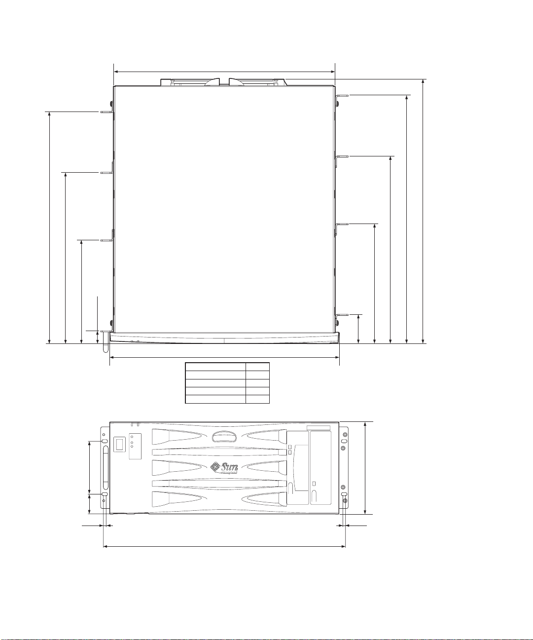
System unit components are housed in a 4RU rack-mounting enclosure designed to
NEBS Level 3 standards. Overall chassis dimension (width x depth x height) are
445.2mm x 508.1mm x 176.6mm (17.52in. x 20.00in. x 6.95in.). Flange mounting kits
are available for installing the system in 19-inch, 23-inch, 24-inch and 600-mm racks
(see
FIGURE 2-1). A slide adaptor kit is also available.
1-1
431.0
508.1
477.9
446.4
329.55
199.55
37.7 101.8
5.3
25.0
445.2
DIMENSION 'A'
19 in. FLANGES
23 in. FLANGES
24 in. FLANGES
600mm FLANGES
DIMENSION 'A'
470.4
470.4
561.3
595.8
518.2
361.05
231.05
56.5
176.6
5.3
FIGURE 1-1 Netra T4 System Dimensions and Mounting Options (dimensions in mm)
1-2 Netra T4 AC100/DC100 Service and System Reference Manual • August 2001

System unit electronics are contained on a single printed circuit board
(motherboard). The motherboard contains the CPU modules, memory, system
control application-specific integrated circuits (ASICs) and I/O ASICs.
A fully-configured system weighs approximately 27.3kg (60lb).
Operating Environment
■ Solaris 8 Update 4/01 and Update 7/01
Power
■ Rack mounting enclosure with one single-feed 100–240VAC power supply unit
(AC100) or one twin-feed –48VDC / –60VDC power supply unit (DC100)
Processors
■ Support for up to two 750MHz UltraSPARC III processor modules, each with
8MByte Ecache
Memory
■ Support for up to eight 128MByte-, 256Mbyte-, 512MByte- or 1GByte Next
Generation Dual Inline Memory Module (NG-DIMMS) installed in two groups of
four providing from 512MByte to 8GByte of memory
IO
■ Four PCI 2.1 compliant slots:
■ one long
■ two long
■ one short
■ One 10/100BaseT Ethernet connection
■ One Fast-Wide SCSI connection
■ Four USB connections (two twin Series A ports) @ 12Mb/s
■ One external FC-AL connection
■ Two internal FC-AL connections for hard disks
■ Two RS232/RS423 serial ports
■ One parallel port
1. Upto 312mm long
2. Upto 174.6mm long
1
64/32-bit, 66/33MHz
1
64/32-bit, 33MHz
2
64/32-bit, 33MHz
Chapter 1 System Description 1-3

■ One DB-15 LOMlite2 alarms relay port
■ One RJ45 LOMlite2 alarms serial port
System Configuration
■ I2C system configuration card reader (SCCR)
Storage
■ Up to two FC-AL 1-inch hot swap hard disks (36GByte)
■ External hardware RAID support through PCI
■ Software RAID support Sun Logical Volume Manager (SLVM)
■ Up to two removable media drives (DVD-ROM and DDS-4 DAT)
Reliability, Availability and Serviceability
■ LOMLite 2 automatic system recovery
■ Remote diagnosis via Solaris and LOMLite 2
■ Hot swap disks
■ Diagnostic LEDs
■ Environmental monitoring
■ Field Replaceable Unit (FRU) ID support
Documentation
■ Installation and User’s Guide
■ Service and System Reference Manual (this document)
■ Compliance and Safety Manual
■ Release Notes
Software Support
■ Lights Out Management 2.0 (LOMlite2)
■ SLVM (Sun Logical Volume Manager)
■ SunVTS™ 4.4 (Sun Validation Test Suite)
■ SunMC (Sun Management Center)
■ SNMP (Sun Netra SNMP Management Agent)
■ SunCluster
■ SRS/SunUP™ ready
1-4 Netra T4 AC100/DC100 Service and System Reference Manual • August 2001

PCI Card Support
■ SunSwift™
■ Fast Ethernet
■ Quad Fast Ethernet (QFE)
■ High Speed Serial Interface (HSI)
■ Serial Asynchronous Interface (SAI)
■ ATM-155
■ Dual Differential SCSI
■ Gigabit Ethernet
■ FC-AL
■ FC-AL and Gigabit Ethernet combination
■ SSL Crypto Accelerator
1.2 System Unit Components
The system unit components are listed by part number in Appendix A.
Note – The part numbers listed in Appendix A were correct when this manual was
published but they are subject to change without notice. Numerical references
illustrated in
Refer to your authorized Sun sales representative or service provider to confirm a
part number before you order a replacement part.
FIGURE A-1 correlate to the references listed in TABLE A-1 and TABLE A-2.
1.3 Environmental Performance
The principal environmental requirements are given in Section B.3, “Environmental
Specification” on page B-4.
Chapter 1 System Description 1-5

1.4 LEDs
The Netra T4 server has three sets of LEDs that show the status of the system.
1.4.1 System LEDs
The system LEDs are located behind the front fascia, immediately to the right of the
ON/STBY switch as you face the unit, as shown in
Light pipes transmit the Power, System, Alarm1, Alarm2 and Fault LEDs through
the fascia and are visible from the front of the system. To view the remaining LEDs,
you must lower the front fascia.
FIGURE 1-2.
DC SYSTEMS
ONLY
SYSTEM
ALARM 1
ALARM 2
DC-A
DC-B
HDD 0 HDD 1
SYSTEM
ALARM 1
ALARM 2
HDD 0 HDD 1
AC100 DC100
FIGURE 1-2 Front Panel System LEDs
1-6 Netra T4 AC100/DC100 Service and System Reference Manual • August 2001

The Alarm1, Alarm2, System and Fault LEDs are mirrored on the LOMlite2 card
visible from the rear of the system (see Section 1.4.2, “LOMlite 2 LEDs” on page 1-8).
TABLE1-1 Front Panel System LED Functions
LED Icon/Legend Color Function
Power Green Illuminated continuously while power is
supplied to the system.
System
1
SYSTEM Green Off (or reset) during power up procedures
and illuminated when UNIX is running and
the Alarms driver is installed. This LED is
reset by a hardware Watchdog timeout, or
whenever the user-defined Alarm3 is
asserted.
Alarm1
1
ALARM1 Amber Illuminated whenever the user-defined
Alarm1 is asserted
Alarm2
1
ALARM2 Amber Illuminated whenever the user-defined
Alarm2 is asserted
Input A OK DC-A Green Illuminated when the input voltage from
feeder A is above 37V
Off when Input A is below 35V
Not used by the AC100
Input B OK DC-B Green Illuminated when the input voltage from
feeder B is above 37V
Off when Input B is below 35V
Not used by the AC100
Fault
1
Amber Driven by the LOMlite2 module under
identified system fault conditions
Disk0 Active
Disk0 OK to
Remove
2
2
Green Illuminated when Disk0 is active
Blue Illuminated, in response to a user request,
when Disk0 can be removed safely without
affecting the system operation
Disk0 Fault
2
Amber Illuminated when the system has identified a
fault in Disk0
Chapter 1 System Description 1-7
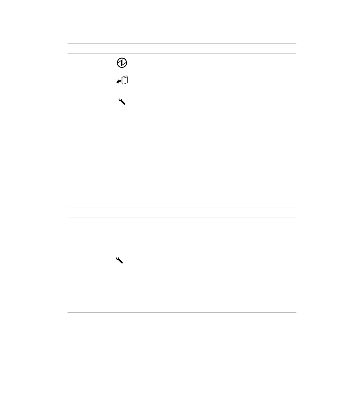
TABLE1-1 Front Panel System LED Functions (Continued)
LED Icon/Legend Color Function
Disk1 Active
2
Green Illuminated when Disk1 is active
Disk1 OK to
Remove
Disk1 Fault
1. These LEDs are duplicated on the LOMlite2 card face plate (see Section 1.4.2, “LOMlite 2 LEDs” on page 1-8).
2. Lower the front fascia to view these LEDs.
2
2
1.4.2 LOMlite 2 LEDs
The LOMlite2 status LEDs, which mirror the alarm status and power LEDs on the
front panel, are located on the rear of the system, between the LOMlite2 DB-15
alarms relay port and RJ45 serial port as shown in
TABLE1-2
LED Icon/Legend Color Function
Alarm 1 1 Amber Illuminated when user-defined Alarm 1 is
Alarm 2 2 Amber Illuminated when user-defined Alarm 2 is
Fault Amber Driven by the LOMlite 2 card and
LOMlite2 Status LED Functions
Blue Illuminated, in response to a user request,
when disk1 can be removed safely without
affecting the system operation
Amber Illuminated when the system has identified a
fault in Disk1
FIGURE 1-3.
asserted
asserted
illuminated when a system fault condition
exists
System SYS Green Illuminated when Solaris is running and the
LOMlite2 driver is installed
Off while the system is powering up
Reset by watchdog timeout, assertion of userdefined Alarm 3
1-8 Netra T4 AC100/DC100 Service and System Reference Manual • August 2001

Alarms Service
Port
LEDs
ALARM
1
2
SYS
Warning: Power off system before removing
or replacing System Configuration Card
FIGURE 1-3 LOMLite2 Status LEDs
Serial Port
LOM SERIAL
Chapter 1 System Description 1-9

1.4.3 PSU LEDs
The PSU status LEDs are located at the left hand end of the PSU (see FIGURE 1-4).
1.4.3.1 Netra T4 AC100 System
TABLE1-3 PSU Status LED Functions
LED Icon Color Function
AC Input OK Green Illuminated when AC is present and above
PSOK Green Illuminated when output voltages are within
Fail Amber Illuminated when PSU is in a Fault condition
85VAC
operating range
Flashes when PSU is in Standby mode
Off when PSU is enabled (OK)
Flashes if unit is within 10˚C of thermal
shutdown or has shutdown
FIGURE 1-4 PSU Status LEDs (Netra T4 AC100 System)
1-10 Netra T4 AC100/DC100 Service and System Reference Manual • August 2001

1.4.3.2 Netra T4 DC100 System
TABLE1-4 PSU Status LED Functions (Netra T4 DC100)
LED Icon Color Function
Fail Amber Illuminated when PSU is in a Fault condition
PSOK Green Illuminated when output voltages are within
Input B OK B Green Illuminated when input voltage from feeder
Input A OK A Green Illuminated when input voltage from feeder
Off when PSU is not enabled (OK)
Flashes if unit is within 10˚C of thermal
shutdown or has shutdown
operating range
Flashes when PSU is in Standby mode
B is above 37V
Off when Input B is below 35V
A is above 37V
Off when Input A is below 35V
FIGURE 1-5 PSU Status LEDs (Netra T4 DC100 System)
Chapter 1 System Description 1-11

1-12 Netra T4 AC100/DC100 Service and System Reference Manual • August 2001

CHAPTER
2
Power-On Self Test
This chapter describes how to initiate power-on self test (POST) diagnostics.
The chapter contains the following topics:
■ Section 2.1, “POST Overview” on page 2-1
■ Section 2.2, “Pre-POST Preparation” on page 2-3
■ Section 2.3, “Running POST” on page 2-4
■ Section 2.4, “POST Diagnostic Levels” on page 2-4
2.1 POST Overview
POST is a firmware program that is useful in determining if a portion of the system
has failed. POST verifies the core functionality of the system, including the CPU
module(s), motherboard, memory, and some on-board I/O devices, and generates
messages that can be useful in determining the nature of a hardware failure. POST
can be run even if the system is unable to boot.
POST detects most system faults and is located in the motherboard OpenBoot™
PROM. POST can be set to run by the OpenBoot program at power up by setting two
environment variables, the diag-switch? and the diag-level flag, which are
stored on the System Configuration Card.
POST diagnostic and error message reports are displayed on a console.
2-1

2.1.1 How to Use POST
POST runs automatically when the system power is applied, and following an
automatic system reset if both of the following conditions apply:
■ diag-switch? is set to true (default is false)
■ diag-level is set to min, max or menus (default is min)
If diag-level is set to min or max, POST performs an abbreviated or extended test,
respectively (see Section 2.4, “POST Diagnostic Levels” on page 2-4).
If diag-level is set to menus, a menu of all the tests executed at power up is
displayed (
CODE EXAMPLE 2-1 POST Test Menu
{0}* Xcall Test
{0}Sending Cross Calls to CPU AID 1
{0} 0 Return
{0} 1 Run all Tests in this Menu
{0} 2 Change Test Control Flags
{0} 3 * Reset Menu
{0} 4 * CPU Tests
{0} 5 * Ecache Tests
{0} 6 * Memory Tests
{0} 7 * Schizo Tests
{0} 8 * RIO Tests
{0} 9 * Estar Test (UP only)
{0} a * ECC Tests
{0} b * MP Tests
{0} c * BIST
{0} d * System Frequency and CPU Ratio
{0} e * I2C/Fan/Temperature/Smart card
{0} f * Run POST
{0} 10 * Return to OBP
{0}Selection
CODE EXAMPLE 2-1):
2-2 Netra T4 AC100/DC100 Service and System Reference Manual • August 2001

Selection 2 enables you to change the test control flags (CODE EXAMPLE 2-2):
CODE EXAMPLE 2-2 POST Test Control Flags Menu
{0}Selection:2
{0} 0 Return
{0} 1 Run all Tests in this Menu
{0} 2 Change Test Control Flags
{0} 3 * Toggle Trace Flag - c
{0} 4 * Toggle Loop-a-test flag - l
{0} 5 * Toggle Loop-on-error flag - e
{0} 6 * Toggle Print-all-error flag - p
{0} 7 * Display current state of all flags
{0} 8 * Help on Test Flags
{0}Selection:
Note – If diag-switch = false, POST is disabled. If diag-switch = true and
diag-level = max, POST runs in max mode. If diag-switch = true and
diag-level = min, POST runs in min mode.
To run POST, power cycle the system.
2.2 Pre-POST Preparation
1. Connect a terminal to the LOM serial port on the Netra T4 server to view POST
progress and error messages. See Section G.1, “Connecting to the LOM Serial
Port” on page G-1.
Note – By default, the input and output device is the LOM serial port. To direct
POST output to ttya or ttyb, set both input-device and output-device to ttya
or ttyb:
2. Set the diag-switch? and diag-out-console configuration variables to true:
ok setver diag-switch? true
ok setver diag-out-console true
Chapter 2 Power-On Self Test 2-3

Alternatively, from the shell prompt:
# eeprom diag-switch?=true
# eeprom diag-out-console=true
3. Set the diag-level configuration variable to max or min (see Section 2.4, “POST
Diagnostic Levels” on page 2-4).
ok setenv diag-level
or
# eeprom diag-level=
Note – The default value is min.
value
value
2.3 Running POST
To run POST:
● Initiate POST using one of the following methods:
a. Briefly press the power ON/STBY switch to power cycle the system.
b. At the LOM prompt, type
poweroff followed by poweron.
2.4 POST Diagnostic Levels
Two levels of POST are available: maximum ( max) level and minimum (min) level.
The system initiates the selected level of POST based on the setting of diag-level,
a configuration variable.
2-4 Netra T4 AC100/DC100 Service and System Reference Manual • August 2001

The time required to complete POST depends on the CPU configuration and the
amount of installed memory. The following table lists the approximate time required
to complete the POST for single and dual processor systems with varying memory
installed, for diag-level variable settings of max and min.
TABLE2-1 POST Completion Times
CPU and Memory max setting min setting
2P, 4GByte 8 minutes 5 minutes
2P, 1GByte 4 minutes 6 minutes
1P, 2GByte 4 minutes 7 minutes
1P, 512MByte 3 minutes 5 minutes
The default value for diag-level is min.
2.4.1 diag-level Variable Set to max
When the diag-level variable is set to max, POST enables an extended set of
diagnostic-level tests. See
CODE EXAMPLE E-1 in Appendix E provides an example of the POST output from a
system with two 750MHz CPUs and 4Gbyte of memory, and with the diag-level
variable set to max.
TABLE 2-1 for approximate completion times.
2.4.2 diag-level Variable Set to min
When the diag-level variable is set to min, POST enables an abbreviated set of
diagnostic-level tests. See
CODE EXAMPLE E-2 in Appendix E provides an example of the POST output from a
system with two 750MHz CPUs and 4Gbyte of memory, and with the diag-level
variable set to min.
TABLE 2-1 for approximate completion times.
Chapter 2 Power-On Self Test 2-5

2.4.3 Error Messages
CODE EXAMPLE 2-3 shows a sample error message at the console:
CODE EXAMPLE 2-3 Sample POST Console Error Message
Power On Self Test Failed.
Cause: DIMM J0406 or System Board
ok
CODE EXAMPLE 2-4 shows a sample error message at the serial port.
CODE EXAMPLE 2-4 Sample POST Serial Port Error Message
{0} ERROR: TEST=*Memory Initial area TESTID=2
{0} H/W under test=*MAIN MEMORY
{0} Fault address 00000000.00000010
{0} Fault status 00000002.0000004f
{0} (CE) Correctable system data ECC error
{0} CPU data bit 6
{0} Memory data bit 146
{0} DIMM connector J0406
{0} Connector pin 124
{0} CPMS slice 124
2-6 Netra T4 AC100/DC100 Service and System Reference Manual • August 2001

CHAPTER
3
SunVTS
This chapter contains an overview of the Sun Validation Test Suite 4.4 (SunVTS™)
diagnostic tool. You can use SunVTS to validate a system when troubleshooting and
during periodic maintenance.
This chapter contains the following topics:
■ Section 3.1, “The Validation Test Suite” on page 3-1
■ Section 3.1.1, “SunVTS Requirements” on page 3-2
■ Section 3.1.2, “SunVTS References” on page 3-2
■ Section 3.1.3, “Installation” on page 3-3
■ Section 3.1.4, “New and Modified Features and Options” on page 3-3
■ Section 3.2, “SunVTS Tests” on page 3-6
3.1 The Validation Test Suite
SunVTS Version 4.4 is the Sun online Validation Test Suite supplied with the
Netra T4 system.
SunVTS is a comprehensive software diagnostic package that tests and validates
hardware by verifying the connectivity and functionality of most hardware
controllers, devices, and platforms.
SunVTS can be tailored to run on various types of systems ranging from desktops to
servers and has many features that you can customize to meet the varying
requirements of differing diagnostic situations.
3-1

SunVTS executes multiple diagnostic tests from a graphical user interface (GUI) or
TTY interface that provide test configuration and status monitoring.
The SunVTS interface can run on one system to display the SunVTS test session of
another system on the network.
SunVTS is distributed with each Solaris release. It is located on the Sun Computer
Systems Supplemental CD.
3.1.1 SunVTS Requirements
Your system must meet the following requirements to run SunVTS:
■ The SunVTS packages must be installed. The main package is SUNWvts. There
are additional supporting packages that differ with the revision of the Solaris
operating system that is installed. See also Section 3.1.3, “Installation” on
page 3-3 and the corresponding SunVTS documentation.
■ The system must be booted to the multiuser level (level 3).
■ To run SunVTS with a GUI (CDE or Open Look), that GUI must be installed.
Otherwise, run SunVTS with the TTY-mode interface.
3.1.2 SunVTS References
To find out more information about the using SunVTS, refer to the SunVTS
documentation for the Solaris release that you are running.
The SunVTS documents are part of the Solaris on Sun Hardware AnswerBook
collection. This AnswerBook collection is pre installed on the hard disk of new
systems. It is also distributed on the Software Supplemental CD that is part of each
Solaris Media Kit release and is also accessible at http://docs.sun.com.
TM
The following list describes the contents of each SunVTS document:
■ SunVTS User’s Guide describes how to install, configure, and run the SunVTS
diagnostic software.
■ SunVTS Test Reference Manual provides details about each individual SunVTS
test.
■ SunVTS Programmer’s Guide supports the development of custom tests.
3-2 Netra T4 AC100/DC100 Service and System Reference Manual • August 2001

3.1.3 Installation
The SunVTS 4.4 software comprises four installation packages:
■ SUNWvts—SunVTS kernel, user interface and tests
■ SUNWvtsx—SunVTS 64-bit package
■ SUNWvtsol—SunVTS user interface
■ SUNWvtsmn—SunVTS man pages
For details of the installation procedure, refer to the Netra T4 AC100/DC100
Installation and User’s Guide.
3.1.4 New and Modified Features and Options
The following additions have been made to support the Netra T4 system:
■ Tests have been included for the new components of the hardware platform.
■ Remote features enable you to interface to SunVTS from a remote system.
■ Multiple user interfaces can monitor and run tests concurrently.
■ A test scheduler enables you to specify groups of tests to be conducted in a
predefined order. Tests in a group are executed concurrently so that all tests in
one group complete before the tests in another group begin.
■ A new SunVTS message format displays the information re-ordered and labeled:
<timestamp> <hostname> “SunVTS:”[VTSID <vts msgid>]
<modulename> [.<submodulename>] [.<insttnum>].<vts_msgtype>]
[<device_pathname>:] <msg_txt>
08/05/01 17:19:47 vrij SunVTS: VTSID 34 disktest.VERBOSE c0t0d0:
“number of blocks 3629760”
Chapter 3 SunVTS 3-3

3.1.4.1 New and Modified Tests and Commands
The following commands have been added to this release of SunVTS.
TABLE3-1 New SunVTS Commands
Command Function
testadd Adds a test’s resource object files to the SunVTS shared object
library (contained in the SUNWvtstk package)
testrm Removes a test’s resource object file from the SunVTS shared object
library (contained in the SUNWvtstk package)
testinfo Lists all the resource object files from the SunVTS shared object
library (contained in the SUNWvtstk package)
vts_cmd Enables direct control of SunVTS from your program or scripts on a
remote machine
connect Enables a user interface to connect to a SunVTS kernel on any
system on a network
trace System call tracing that assists in tracing test flows through the
system interfaces
Record/Replay Enables test sequences and forks to be recorded and replayed to
improve failure reproducibility
Reprobe Searches and recompiles (reprobes) the system’s configuration on
demand
Note – To add a third party test executable binary, add the test to
/opt/SUNWvts/bin/sparcv9, then modify the
/opt/SUNWvts/bin/sparc9/.customtest file.
3-4 Netra T4 AC100/DC100 Service and System Reference Manual • August 2001

The commands are shown in the SunVTS GUI menus (FIGURE 3-1):
SunVTS Diagnostic
Commands View
Options
Reports DSched
Open System Map
Close System Map
Start Testing
Stop Testing
Reset
Start T est
Start Test with record
Replay
Suspend
Resume
Connect to host
Trace Test
Reprobe system
Performance meter
Exit SunVST
FIGURE 3-1 SunVTS Menu Bar
UI and kernel
UI only
kernel only
3.1.5 Starting SunVTS
You can start SunVTS in one of four modes, depending on whether you are
executing locally or remotely, on a CDE GUI, OpenLook GUI, or in TTY mode:
■ To run SunVTS kernel and default GUI on the local system, type:
System configuration
Log Files
Thresholds
Notify
Schedules
Test Execution
Advanced
Option Files
Start DS
Show DS
Quit Options
Quit DS UI only
Quit DS
# cd /opt/SUNWvts/bin
# ./sunvts
■ To run SunVTS kernel and OpenLook GUI on the local system, type:
# cd /opt/SUNWvts/bin
# ./sunvts -l
Chapter 3 SunVTS 3-5

■ To run SunVTS kernel in TTY mode on the local system, type:
# cd /opt/SUNWvts/bin
# ./sunvts -t
■ To connect and test a remote system, hostname, but display the GUI on the local
host, type:
# cd /opt/SUNWvts/bin
# ./sunvts -h
Note – The latest SunVTS features may not be supported by the SunVTS OpenLook
GUI.
3.2 SunVTS Tests
This section lists the tests available in SunVTS 4.4. Some tests have been modified
and new tests have been added to support the Netra T4 hardware platform.
TABLE3-2 SunVTS Processor Tests
Test Function
cputest This new test checks the specific functionality of the SPARC
processor data path, including:
■ g0 register functionality
■ Compress/Uncompress/Compare command
Legacy Tests These include:
■ systest—tests the I/O, memory and CPU channels
■ fputest—tests the floating point unit
■ mptest—tests two or more processors by having them access a
shared memory page
3-6 Netra T4 AC100/DC100 Service and System Reference Manual • August 2001

TABLE3-3 SunVTS Memory Tests
Test Function
Legacy Tests These include:
■ pmemtest—tests the physical memory by targeting parity, ECC,
memory read, and addressing problems
■ vmemtest—tests the virtual memory and the swap partitions of
the disks
TABLE3-4 SunVTS Storage Device Tests
Test Function
dvdtest This new test checks the DVD-R drive by reading the DVD.
qlctest This new test checks the ISP2200A FC-AL controller. The sub tests
include:
■ Revision checks
■ Internal loopback tests
■ External loopback tests (require external loopback cable)
Legacy Tests These include:
■ cdtest—tests the CD-ROM drive by reading the CD
■ tapetest—tests tape devices by writing, reading and verifying
synchronous and asynchronous data blocks
TABLE3-5 SunVTS Network Tests
Test Function
netlbtest This new test checks the ERI and GEM Ethernet controllers by
performing internal and external loopback tests (replaces gemtest).
nettest This system-to-system legacy test covers all networking devices
found in the system.
TABLE3-6 SunVTS Communications Port Tests
Test Function
usbkbtest This new test covers the keyboard and mouse.
Legacy Tests These include:
■ sptest—tests the serial sync. and async. ports
■ ecpptest—tests the parallel ports
Chapter 3 SunVTS 3-7

TABLE3-7 SunVTS Custom Test
Test Function
cpupmtest This new test checks the CPU power management functionality.
Note – Test failures occur if you run nettest and netlbtest simultaneously.
3.2.1 Guide to Using SunVTS 4.4
The following guidance notes points are included to help you use SunVTS 4.4.
■ The packages SUNWeswsa, SUNWsycfd, SUNWesnta and SUNWeswgn are no
longer required or supplied for physical mapping support.
■ The disktest probe does not premount any partitions by default. You can set the
environment variable BYPASS_FS_PROBE to zero to force all unmounted
partitions to premount.
■ Premounting will not take place, even if you have enabled it, if the disktest probe
detects the presence of Veritas or Solstice DiskSuite.
■ If you run a media subtest on a disk partition in WriteRead mode, data corruption
can occur if the partition is shared with other programs.
■ An option file created when BYPASS_FS_PROBE was set to 0 may not load when
BYPASS_FS_PROBE is set to 1. If required, create option files for both states of
BYPASS_FS_PROBE
■ SunVTS (Kerebos SEAM) security is now on by default. To turn security off, edit
the security file /opt/SUNvts/bin/.sunvts to include a “+” in the HOST
section. This will make all the listed hosts trusted hosts.
■ Physical mapping is supported only on systems that support configd.
■ Do not mix CDE and OpenLook environments.
■ The files .customtest and .customtest_OtherDevices are separate files in
the 64-bit version of SunVTS. They are installed in /opt/SUNWvts/bin/spacv9,
and not /opt/SUNWvts/bin as is the case for the 32-bit version.
■ The environment variable VTS_PM_PATH is used to locate the pix map files when
SunVTS is not installed in the default base directory (/opt).
■ The following tests have been renamed:
■ spif -> spiftest
■ pmem -> pmemtest
■ vmem -> vmemtest
■ The following tests are not supported in 64-bit mode:
■ cg14test
■ isdntest
■ tcxtest
■ The physical map view displays only one level of the hierarchy. To view the
complete hierarchy, use the logical view.
3-8 Netra T4 AC100/DC100 Service and System Reference Manual • August 2001

CHAPTER
4
Troubleshooting
This chapter describes how to troubleshoot possible hardware problems and
suggests corrective actions.
This chapter contains the following topics:
■ Section 4.1, “Power-On Failure” on page 4-2
■ Section 4.2, “System LEDs” on page 4-2
■ Section 4.3, “Drive Failure” on page 4-2
■ Section 4.4, “Power Supply Unit Troubleshooting” on page 4-4
■ Section 4.5, “OpenBoot PROM Diagnostics” on page 4-7
■ Section 4.6, “OpenBoot Emergency Procedures” on page 4-30
Caution – Regardless of the position of the ON/STBY switch, when an AC power
cord remains connected to the system, hazardous voltage is always present within
the power supply.
Caution – Wear an antistatic wrist strap and use an ESD-protected mat when
!
!
handling components. When servicing or removing system unit components, use an
antistatic wrist strap with a 10mm press stud connection and attach the antistatic
wrist strap to the press stud at the rear or front of the chassis before removing the
top access cover.
Caution – Owing to the weight of the unit, two persons are required to remove the
unit from and replace it in the rack.
4-1

4.1 Power-On Failure
This section provides examples of power-on failure symptoms and suggested
actions.
Symptom
The system does not power up when you press the ON/STBY switch.
Action
■ Ensure that a PSU is installed and properly seated. Check that the three PSU
fixing screws have been tightened.
■ Ensure that the AC power cord is properly connected to the system and to the
wall socket. Verify that the wall socket is supplying AC power to the system.
■ Press the ON/STBY switch. If the system does not power on, the CPU module(s)
may not be properly seated. Inspect the CPU module(s) for proper seating, and
press the ON/STBY switch again.
■ If the AC power wall socket is live and the CPU module(s) are properly seated,
but the system does not power on, the PSU may be defective. Check the status of
the PSU LEDs and see Section 4.4, “Power Supply Unit Troubleshooting” on
page 4-4.
4.2 System LEDs
The system LEDs located on the front and rear system panels provide information
about the status of the system and many of its subsystems. Refer to Section 1.4,
“LEDs” on page 1-6 for a description of their function.
4.3 Drive Failure
This section provides hard drive, DVD-ROM and DAT drive failure symptoms and
suggested actions.
4-2 Netra T4 AC100/DC100 Service and System Reference Manual • August 2001

Symptom
A hard drive read, write, or parity error is reported by the operating environment or
customer application.
A DVD-ROM or DAT drive read error or parity error is reported by the operating
environment or customer application.
Action
Replace the drive indicated by the failure message. The operating environment
identifies the internal drives, as listed in the following table.
TABLE4-1 Internal Drives Identification
Operating Environment Address Drive Physical Location and Target
c1t1d0s# Left hard drive, LiD/HA 1
c1t2d0s# Right hard drive, LiD/HA 2
c0t6d0s# DVD-ROM drive, target 6 (optional)
c0t5d0s# DAT drive, target 5 (optional)
Note – The # symbol in the operating environment address examples is a numeral
between 0 and 7 that describes the slice or partition on the drive.
Symptom
The DVD-ROM drive fails to respond to commands.
Action
Test the drive response to the probe-scsi command as follows.
Note – To bypass POST, type setenv diag-switch? false at the ok prompt.
Chapter 4 Troubleshooting 4-3

At the OBP ok prompt, type:
ok reset-all
ok probe-scsi-all
If the DVD-ROM drive responds correctly to probe-scsi-all, the message
identified in
successfully probed the device. This is an indication that the motherboard is
operating correctly. If the drive does not respond to the SCSI controller probe,
replace the unresponsive drive.
CODE EXAMPLE 4-2 is displayed; the system SCSI controller has
4.4 Power Supply Unit Troubleshooting
Caution – During the power supply voltage measurement checks, an operational
load must be on the power supply. Ensure that the power supply cables remain
connected to the motherboard.
The section describes how to use a digital volt meter (DVM) to test the power supply
under operational load. See the figures and tables in this section to identify the J3601
and J3603 power connectors.
1. Power off the system and remove the top access panel.
See Chapter 5 for details.
Caution – Use proper ESD grounding techniques when handling components. Wear
an antistatic wrist strap and use an ESD-protected mat. Store ESD-sensitive
components in antistatic bags before placing them on any surface. See Section 5.5,
“Antistatic Precautions” on page 5-5.
Caution – Hazardous voltages are present. To reduce the risk of electrical shock and
danger to personal health, follow the instructions.
2. Check the continuity of the power cables between the PDB and motherboard.
3. Ensure that the PSU is correctly located in the chassis and that the fixing screws
are fully tightened.
4-4 Netra T4 AC100/DC100 Service and System Reference Manual • August 2001

4. Check the PSU LEDs (see Section 1.4.3, “PSU LEDs” on page 1-10) to verify the
status of the PSU.
5. Check that the power cable connectors are properly seated at the PDB and motherboard.
6. Power on the system.
7. Using a DVM, check the power supply output voltages.
See
FIGURE 4-1 for the power supply connector location on the motherboard.
Note – All power supply connectors being tested must remain connected to the
motherboard and PDB.
a. With the negative probe of the DVM placed on a connector ground (GND) pin,
position the positive probe on each power pin.
b. Verify voltage and signal availability as listed in the voltage-pin tables.
8. If any power pin signal is not present with the power supply active, and the
power cables between the PDB and motherboard properly connected, replace the
power supply.
Chapter 4 Troubleshooting 4-5

J2001
SCSI port
J2202
J3001
SCSI ports
J3002
J5301
Enet
FC-AL
J2902
J3603
14
7
8
1
7
14
10
5
J3601
J3608
6
1
2
10
J3603J3604
9
1
1
8
J0407
J0406
J0405
J0404
J0403
J0402
J0401
J3608
J2104
J0407
J0406
J0405
J0404
J0403
J0402
J0401
J0400
J3603
A, B
1
0
1
0
1
0
1
0
CPU
slot 0
J0501
CPU
slot 1
J0701
J2103
33 MHz PCI 4 J2601
LOMLite 2J3501
33 MHz PCI 3 J2501
33 MHz PCI 2 J2401
33/66 MHz PCI 1 J2301
J0601
J0801
Battery
J5002
SEEPROMSEEPROM
J3603J3604
J3601J3601
J2901
J3602
FIGURE 4-1 Power Supply Connector Jack Location
4-6 Netra T4 AC100/DC100 Service and System Reference Manual • August 2001

TABLE4-2 J3601 Voltage-Pin Table
Pin Voltage Pin Voltage
10V8+5V
2 -12V 9 n/a
30V10+5V
4 0V 11 +3.3V
5 0V 12 +12V
6 0V 13 +12V
7 n/a 14 +5V
TABLE4-3 J3603 Voltage-Pin Table
Pin Voltage Pin Voltage
1 +3.3V 8 0V
2 +3.3V 9 0V
3 +3.3V 10 0 V
4 +3.3V 11 0 V
5+5V120V
6+5V130V
7+5V140V
4.5 OpenBoot PROM Diagnostics
The following sections describe the OpenBoot PROM diagnostics. To execute the
OpenBoot PROM on-board diagnostics, the system must be at the ok prompt.
■ Section 4.5.1, “New Features” on page 4-8
■ Section 4.5.2, “New and Modified Commands and Tests” on page 4-10
■ Section 4.5.3, “Device Tree” on page 4-14
■ Section 4.5.4, “Running the Diagnostics” on page 4-18
Chapter 4 Troubleshooting 4-7

4.5.1 New Features
This section summarizes the features supported in OpenBoot 4.2 that are not covered
in the OpenBoot 3.x Command Reference Manual (part no. 806-1377-10) and the
OpenBoot 3.x Quick Reference (part no. 806-2908-10).
■ Universal Serial Bus (USB)
■ FC-AL drive support
■ New device driver support for:
■ PCI prober
■ I2C
■ USB
■ NVRAM
■ FC-AL
■ ERI
■ Safari Giga Plane Two (gptwo) support
■ Autoconfiguration
■ Flash PROM (2MByte) divided into quadrants
■ Quadrant 0—Sun Blade™ 1000 OBP—Start address 0
■ Quadrant 1—Sun Fire™ E280R OBP/Netra T4 OBP—Start address 512k
■ Quadrant 2—POST (shared)—Start address 1.0M
■ Quadrant 3—OBDiag (shared)—Start address 1.5M
■ Flash updates replace two quadrants at a time
■ Quadrant 0 and 1
■ Quadrant 2 and 3
■ Support for:
■ Stop-A
■ Stop-A on ttya (#)
■ Stop-N (emulated by lom> bootmode reset_nvram))
■ Stop-F (emulated by lom> bootmode forth)
■ Stop-D (emulated by lom> bootmode diag)
PCI Buses
Two PCI buses are implemented that are fully independent in terms of address and
data paths, channel engines, gptwo memory physical address space, I/O physical
address space and configuration space. As the device space is not shared between
the two PCI buses, you must access the specific PCI node to view its properties.
4-8 Netra T4 AC100/DC100 Service and System Reference Manual • August 2001

Flash PROM
The flash PROM is divided into quadrants that are dedicated to Sun Blade 1000 OBP,
Sun Fire E280R OBP/Netra T4 OBP, POST and OBDiag, respectively. A flash update
involves two quadrants, either 0 and 1, or 2 and 3. You can download the quadrants
from a standalone utility, bootable DVD-ROM, or from the network. The updates are
available in binary or UNIX shell formats.
During a flash PROM update, the OBP firmware overwrites the upper half of PROM
(where POST resides), keeping the original OBP unchanged. After the new OBP is
tested successfully, the original OBP is overwritten with the new OBP. Finally, after
the OBP is tested again, POST is reloaded into the upper half of PROM.
OBP Prompt
On dual processor systems, the OBP prompt includes the CPU number:
{0} ok
Resets
When the system is first powered up, the configuration is determined using
information stored in the motherboard and CPU EEPROMS (CPU speed, memory
configuration, and so forth) and is saved in the BootBus Controller (BBC) SRAM.
This is termed a Configuration Reset. Subsequent system power cycles generate a
configuration reset.
A Soft Reset occurs on subsequent system resets, which uses the BBC’s SRAM
configuration information. To avoid booting with corrupted configuration
information, a checksum is performed on the data. If the data is found to be corrupt,
the subsequent reset reverts to a configuration reset.
Chapter 4 Troubleshooting 4-9

4.5.2 New and Modified Commands and Tests
The probe and test commands have been modified to include FC-AL and USB
keyboard and mouse, respectively:
TABLE4-4 probe and test Commands
Command New Features
probe-scsi Identifies the devices attached to the FC-AL buses
probe-scsi-all Identifies all devices attached to all SCSI and FC-AL buses
test-all Includes all tests
4.5.2.1 probe-scsi and probe-scsi-all
The probe-scsi diagnostic transmits an inquiry command to internal and external
FC-AL and SCSI devices connected to the system on-board SCSI or FC-AL interface.
If the SCSI device is connected and active, the target address, unit number, device
type, and manufacturer name are displayed.
The probe-scsi-all diagnostic transmits an inquiry command to all devices
connected to the system. The first identifier listed in the display is the SCSI host
adapter address in the system device tree followed by the SCSI device identification
data.
Initiate the probe-scsi diagnostic by typing the probe-scsi command at the ok
prompt and initiate the probe-scsi-all diagnostic by typing the probe-scsi-
all command at the ok prompt.
To perform a probe command, at the ok prompt, ensure that autoboot? is set to
false, then perform a reset-all.
The following code examples identify the probe-scsi and the probe-scsi-all
diagnostic output messages.
CODE EXAMPLE 4-1 probe-scsi Diagnostic Output Message
ok probe-scsi
LiD HA --- Port WWN --- ---- Disk description ---1 1 210000203700ca78 SEAGATE ST39103FCSUN9.0G01479916021084
3 3 210000203708ad4d SEAGATE ST39102FCSUN9.0G09299906F45038
ok
4-10 Netra T4 AC100/DC100 Service and System Reference Manual • August 2001

CODE EXAMPLE 4-2 probe-scsi-all Output Message
ok probe-scsi-all
/pci@8,600000/SUNW,glc@4
LiD HA --- Port WWN --- ---- Disk description ---3 3 210000203708ad4d SEAGATE ST39102FCSUN9.0G09299906F45038
1 1 210000203700ca78 SEAGATE ST39103FCSUN9.0G01479916021084
/pci@8,700000/scsi@6,1
Target 0
Unit 0 Disk SEAGATE ST39173W SUN9.0G2815
/pci@8,700000/scsi@6
Target 6
Unit 0 Removable Read Only device TOSHIBA DVD-ROM SD-M12011B08
ok
4.5.2.2 test alias name, device path, -all
The test diagnostic, combined with a device alias or device path, enables a device
self-test program. If a device has no self-test program, the message
No selftest method for device name is displayed. To enable the self-test
program for a device, type the test command, followed by the device alias or
device path name.
The following code example identifies the test output message.
TABLE 4-5 lists test
alias name selections, their descriptions, and their required preparation.
CODE EXAMPLE 4-3 Test Output Message
ok test net
Testing net
Chapter 4 Troubleshooting 4-11

TABLE4-5 Selected OpenBoot PROM On-Board Diagnostic Tests
Type of Test Description Preparation
test net Performs internal/external loopback
test of the system auto-selected
Ethernet interface.
test-all Sequentially tests system-configured
devices containing selftest.
4.5.2.3 watch-clock
The watch-clock diagnostic displays the result as a seconds counter. During
normal operation, the seconds counter repeatedly increments from 0 to 59. Initialize
the watch-clock diagnostic by typing the watch-clock command at the ok
prompt.
The following code example identifies the watch-clock diagnostic output message.
CODE EXAMPLE 4-4 Watch-Clock Diagnostic Output Message
An Ethernet cable must be
attached to the system and to an
Ethernet tap or hub. If the
Ethernet cable is not correctly
attached the external loopback
test will fail.
Tests are sequentially executed in
device-tree order(viewedwith the
show-devs command).
{0} ok watch-clock
Watching the ‘seconds’ register of the real time clock chip.
It should be ‘ticking’ once a second.
Type any key to stop.
4
4.5.2.4 watch-net and watch-net-all
The watch-net and watch-net-all diagnostics monitor Ethernet packets on the
Ethernet interfaces connected to the system. Good packets received by the system
are indicated by a period (.). Errors such as the framing error and the cyclic
redundancy check (CRC) error are indicated with an X and an associated error
description. Initiate the watch-net diagnostic is by typing the watch-net
command at the ok prompt and initiate the watch-net-all diagnostic by typing
the watch-net-all command at the ok prompt.
4-12 Netra T4 AC100/DC100 Service and System Reference Manual • August 2001
The following code examples identify the watch-net and the watch-net-all
output messages.
CODE EXAMPLE 4-5 watch-net Diagnostic Output Message
{0} ok watch-net
Internal loopback test -- succeeded.
Link is -- up
Looking for Ethernet Packets.
‘.’ is a Good Packet. ‘X’ is a Bad Packet.
Type any key to stop.................................
CODE EXAMPLE 4-6 watch-net-all Diagnostic Output Message
{0} ok watch-net-all
/pci@8,700000/network@5,1
Internal loopback test -- succeeded.
Link is -- up
Looking for Ethernet Packets.
‘.’ is a Good Packet. ‘X’ is a Bad Packet.
Type any key to stop.
4.5.2.5 Serial Port Protocol
The serial port protocol is now programmed as RS232 or RS423 using setenv rather
than by changing a jumper setting.
To change the serial ports to RS232, type:
ok setenv ttya-mode 9600,8,n,1,-,rs232
ok setenv ttyb-mode 9600,8,n,1,-,rs232
ok setenv auto-boot? false
ok reset-all
To change the serial ports to RS423, type:
ok setenv ttya-mode 9600,8,n,1,-,rs423
ok setenv ttyb-mode 9600,8,n,1,-,rs423
ok setenv auto-boot? false
ok reset-all
Chapter 4 Troubleshooting 4-13

4.5.3 Device Tree
The device tree for the Netra T4 system is shown in FIGURE 4-2.
33 MHz PCI 66 MHz EPCI
Internal External
876E SCSI Controller
scsi @ 6 scsi @ 6.1
sd @ 0,0
st @ 4,0
sd @ 6,0 DVD-ROM
ebus@ 5
rtc @ 1,300070
parallel @ 1,300278
serial @ 1,400000:a
serial @ 1,400000:b
LOM-console @ 1,3083f8
LOM-bus @ 1,3062f8
PMC @ 1,300700
gpio @ 1,300600
st @ 0,0
network @ 5,1
RIO
i2c @ 1,2e
dimm @ 0,a0
dimm @ 0,a8
Disks
Tapes
SBC
PCI slot #1
PCI slot #2
PCI slot #3
PCI slot #4
usb @ 5,3
USB external bus
BBC
i2c @ 1.30
nvram @ 0,e0
idprom@ 0,e0
ioexp @ 0,74
hardware-monitor @ 0,56
hardware-monitor @ 0,54
hardware-monitor @ 0,52
ioexp@ 0,4c
fan-control @ 0,4e
lomlite2 @ 0,ae
power-supply @ 0,ac
pci @ 8, 600000pci @ 8, 700000
ISP2200 FC/AL Controller
SUNW,qlc @ 4
HDMP0451 FC/AL HUB
fp @ 0,8 fp @ 0,0
ssd @ w2100002037653317,0
ssd @ w2100002037653328,0
FC/AL external bus
scc-reader ' 0,a6
fcal-backplane @ 0,a4
ioexp @ 0,7a
ioexp @ 0,72
motherboard-fru @ 0,a8
fan-control @ 0,48
temperature @ 0,98
cpu-fru @ 0,a2
temperature @ 0,30
cpu-fru @ 0,a0
FIGURE 4-2 Netra T4 System Device Tree
4-14 Netra T4 AC100/DC100 Service and System Reference Manual • August 2001
The device tree comprises the Parent Node (see TABLE 4-6), the Port ID, and the PCI
Bus Module (PBM) Control Space Offset within the System Bus Controller (SBC)
address space for the parent node.
TABLE4-6 Parent Node Names
Description Child New Name Parent Comments
SCSI Bus scsi pci@8,700000 Internal SCSI (scsi@6)
External SCSI (scsi@6,1)
USB Bus usb pci@8,700000
Ethernet Bus network pci@8,700000
EBus ebus pci@8,700000
FC-AL Bus qlc pci@8,600000
The following values apply to the Netra T4 system:
■ Port ID: 8
■ PBM Control Space Offset:
■ 600000 for 66MHz PCI bus (Bus A)
■ 700000 for 33MHz PCI bus (Bus B)
CODE EXAMPLE 4-7 shows the result of running the show-devs command on the
66MHz PCI bus and
CODE EXAMPLE 4-8 on the 33MHz PCI bus.
CODE EXAMPLE 4-7 66MHz PCI Bus Devices
ok show-devs /pci@8,600000
/pci@8,600000/SUNW,qlc@4
/pci@8,600000/SUNW,qlc@4/fp@0,0
/pci@8,600000/SUNW,qlc@4/fp@0,0/disk
ok
CODE EXAMPLE 4-8 33MHz PCI Bus Devices
ok show-devs /pci@8,700000
/pci@8,700000/scsi@6,1
/pci@8,700000/scsi@6
/pci@8,700000/usb@5,3
/pci@8,700000/network@5,1
/pci@8,700000/ebus@5
/pci@8,700000/scsi@6,1/tape
/pci@8,700000/scsi@6,1/disk
/pci@8,700000/scsi@6/tape
/pci@8,700000/scsi@6/disk
/pci@8,700000/ebus@5/serial@1,400000
Chapter 4 Troubleshooting 4-15

CODE EXAMPLE 4-8 33MHz PCI Bus Devices
ok show-devs /pci@8,700000
/pci@8,700000/ebus@5/lom-console@1,3083f8
/pci@8,700000/ebus@5/lombus@1,3062f8
/pci@8,700000/ebus@5/parallel@1,300278
/pci@8,700000/ebus@5/pmc@1,300700
/pci@8,700000/ebus@5/gpio@1,300600
/pci@8,700000/ebus@5/rtc@1,300070
/pci@8,700000/ebus@5/beep@1,32
/pci@8,700000/ebus@5/i2c@1,30
/pci@8,700000/ebus@5/i2c@1,2e
/pci@8,700000/ebus@5/power@1,30002e
/pci@8,700000/ebus@5/bbc@1,0
/pci@8,700000/ebus@5/flashprom@0,0
/pci@8,700000/ebus@5/lombus@1,3062f8/SUNW,lomv@0,0
/pci@8,700000/ebus@5/i2c@1,30/nvram@0,e0
/pci@8,700000/ebus@5/i2c@1,30/idprom@0,e0
/pci@8,700000/ebus@5/i2c@1,30/ioexp@0,74
/pci@8,700000/ebus@5/i2c@1,30/hardware-monitor@0,56
/pci@8,700000/ebus@5/i2c@1,30/hardware-monitor@0,54
/pci@8,700000/ebus@5/i2c@1,30/hardware-monitor@0,52
/pci@8,700000/ebus@5/i2c@1,30/ioexp@0,4c
/pci@8,700000/ebus@5/i2c@1,30/fan-control@0,4e
/pci@8,700000/ebus@5/i2c@1,30/lomlite2@0,ae
/pci@8,700000/ebus@5/i2c@1,30/power-supply@0,ac
/pci@8,700000/ebus@5/i2c@1,30/scc-reader@0,a6
/pci@8,700000/ebus@5/i2c@1,30/fcal-backplane@0,a4
/pci@8,700000/ebus@5/i2c@1,30/ioexp@0,7a
/pci@8,700000/ebus@5/i2c@1,30/ioexp@0,72
/pci@8,700000/ebus@5/i2c@1,30/motherboard-fru@0,a8
/pci@8,700000/ebus@5/i2c@1,30/fan-control@0,48
/pci@8,700000/ebus@5/i2c@1,30/temperature@0,98
/pci@8,700000/ebus@5/i2c@1,30/cpu-fru@0,a2
/pci@8,700000/ebus@5/i2c@1,30/temperature@0,30
/pci@8,700000/ebus@5/i2c@1,30/cpu-fru@0,a0
/pci@8,700000/ebus@5/i2c@1,2e/dimm-fru@1,ae
/pci@8,700000/ebus@5/i2c@1,2e/dimm-fru@1,ac
/pci@8,700000/ebus@5/i2c@1,2e/dimm-fru@1,aa
/pci@8,700000/ebus@5/i2c@1,2e/dimm-fru@1,a8
/pci@8,700000/ebus@5/i2c@1,2e/dimm-fru@1,a6
/pci@8,700000/ebus@5/i2c@1,2e/dimm-fru@1,a4
/pci@8,700000/ebus@5/i2c@1,2e/dimm-fru@1,a2
/pci@8,700000/ebus@5/i2c@1,2e/dimm-fru@1,a0
ok
4-16 Netra T4 AC100/DC100 Service and System Reference Manual • August 2001

TABLE 4-7 shows the child node names. When accessing a child device from the
parent node, you must identify the child node name, PCI device number and PCI
function number.
TABLE4-7 Child Node Names
Description Child Node Name Comment
Serial Port serial Old name (se)
Parallel Port (off Ebus) parallel Old name (ecpp)
LOMlite2 Card lom-console
General Purpose I/O Port gpio
I2C Bus i2c
Real Time Clock rtc
BootBus Controller bbc
Flash PROM flashprom
Motherboard motherboard
Temperature Sensor temperature
CPU cpu
ID PROM (off I2C bus) idprom
NVRAM (off I2C bus nvram
Memory DIMM (off I2C bus) dimm
The following device ID field values are assigned to the Netra T4 system:
■ Device ID 4: FC-AL
■ Device ID 5: usb, ebus, eri, serial, parallel, gpio
■ Device ID 6: Internal and external SCSI
Example: FC-AL Internal Disk Drive Path
/pci@8,60000/SUNW,qlc@4/fp@0,0/ssd@w2100002037653317,0
where (from left to right):
■ pci represent the PCI bus
■ 8 represents the Netra T4 platform
■ 600000 represents 66MHz PCI
■ qlc represents the FC-AL controller driver
■ 4 is the FC-AL device number
Chapter 4 Troubleshooting 4-17

■ fp is the FC-AL port driver (HUB)
■ 0,0 are the FC-AL HUB device number and FC-AL HUB function number
■ ssd represents the disk driver
■ w# is the World Wide ID number
Example SCSI Internal Disk Drive Path
/pci@8,7000000/scsi@6/sd@1,0
where (from left to right):
■ pci represent the PCI bus
■ 8 represents the Netra T4 platform
■ 700000 represents 33MHz PCI
■ scsi represents the SCSI controller driver
■ 6 is the SCSI device number
■ sd represents the SCSI disk driver
■ 1,0 are the SCSI device number and SCSI function number
4.5.4 Running the Diagnostics
This section contains the following OpenBootDiag diagnostic information:
■ Section 4.5.4.1, “OBDiag Tests” on page 4-19
■ Section 4.5.4.2, “Starting the OBDiag Menu” on page 4-22
■ Section 4.5.4.3, “SUNW,lomv@0,0” on page 4-24
■ Section 4.5.4.4, “SUNW,qlc@4” on page 4-25
■ Section 4.5.4.5, “bbc@1,0” on page 4-25
■ Section 4.5.4.6, “ebus@5” on page 4-25
■ Section 4.5.4.7, “flashprom@0,0” on page 4-26
■ Section 4.5.4.8, “gpio@1,300600” on page 4-26
■ Section 4.5.4.9, “i2c@1,2e” on page 4-26
■ Section 4.5.4.10, “i2c@1,30” on page 4-27
■ Section 4.5.4.11, “network@5,1” on page 4-27
■ Section 4.5.4.12, “parallel@1,300278” on page 4-27
■ Section 4.5.4.13, “pmc@1,300700” on page 4-28
■ Section 4.5.4.14, “ortc@1,300070” on page 4-28
■ Section 4.5.4.15, “scsi@6” on page 4-28
■ Section 4.5.4.16, “scsi@6,1” on page 4-29
■ Section 4.5.4.17, “serial@1,400000” on page 4-29
■ Section 4.5.4.18, “usb@5,3” on page 4-29
■ Section 4.5.4.19, “test-all” on page 4-30
4-18 Netra T4 AC100/DC100 Service and System Reference Manual • August 2001

Note – Set the diag-level variable to min prior to performing these tests. This can
be done at the ok prompt or within the obdiag menu .
The OpenBoot diagnostic (OBDiag) is a menu-driven set of diagnostics that reside in
flash PROM on the motherboard. OBDiag can isolate errors in the following system
components:
■ Motherboard
■ DVD-ROM and DAT drives
■ Hard drive
■ Any option card that contains an onboard self-test
OBDiag performs root-cause failure analysis on the referenced devices by testing
internal registers, confirming subsystem integrity, and verifying device functionality.
On the motherboard, OBDiag tests not only the motherboard but also its interfaces:
■ PCI
■ SCSI
■ Ethernet
■ Serial
■ Parallel
■ USB
■ I2C
■ FC-AL
4.5.4.1 OBDiag Tests
Each self-test executes independently and returns a zero if it completes successfully,
or a non zero and an error report if it is unsuccessful. Diagnostic configuration
variables determine the level of coverage, execution flow, and the corresponding
output. These variables are configured using the setenv command.
TABLE4-8 OBDiag Configuration Variables
Variable Function Possible Values Default Value
diag-level Determines how the tests are performed min
diag-passes Defines the number of times the self-test
1. When diag-level is set to min, OBDiag performs abbreviated tests.
2. When diag-level is set to max, OBDiag performs extended tests.
3. Where “#” is the number of times the tests are performed (integer).
method(s) are performed
max
3
#
1
2
min
1
Chapter 4 Troubleshooting 4-19

The new tests, and their features, for the Netra T4 system are summarized in
TABLE 4-9.
TABLE4-9 Netra T4 System-Specific OBDiag Self Tests
Test Test Function
SUNW,lomv@0,0 LOMlite2 Selftest
■ Lomlite registers test
SUNW,qlc@4 FC-AL/SCSI Enclosure Services (SES) Subsystem Tests
■ FC-AL (ISP2200A)
■ PCI configuration space register test
■ FPM, FB, DMA, PBUI and RISC register test
■ Mailbox tests
■ Memory bank tests
■ RISC RAM test
■ FIFO load and unload test
■ Disk Tests
■ Read/Write/Restore test
■ Seek test
■ Random seek test
■ Hour glass seek test
■ Built-in self test (BIST)
■ SES Tests
■ Get supported diagnostic page test
■ Get configuration page test
■ Get enclosure status page test
bbc@1,0 BBC Self Test
■ Register test
ebus@5 RIO Ebus Self Test
■ PCI configuration space register test
■ Ebus register test
■ DMA register test
■ DMA functional test
■ TCR register test
■ AUX I/O register test
flashprom@0,0 Flash Self Test
■ Flash read test
■ Flash write test (manufacturing test only)
gpio@0,300600 Super I/O Self Test
■ General purpose I/O test
i2c@1,2e I2C Self Test
■ I2C bus test
4-20 Netra T4 AC100/DC100 Service and System Reference Manual • August 2001

TABLE4-9 Netra T4 System-Specific OBDiag Self Tests (Continued)
Test Test Function
i2c@1,30 I2C Self Test
■ I2C bus test
network@5,1 RIO-GEM Self Test (10/100Mbits)
■ PCI configuration space register test
■ RIO-GEM register test
■ Internal loopback (RIO-GEM level)
■ Internal loopback (Lucent 6612 PHY level)
■ External loopback (requires RJ45 loopback connector)
parallel@1,300278 SuperI/O Self Test
■ ECP and EPPP mode parallel port test (requires loopback
connector)
pmc@1,300700
rtc@1,300070 SuperI/O Self Test
■ Advanced power controller/Real time clock (TOD) test
scsi@6 SCSI (53C875) Self Test
■ SCSI (53C875) register test
■ SCSI timer test
■ SCSI DMA test
■ SCSI loopback test
■ SCSI wide transfer test
■ SCSI BIST test
scsi@6,1 SCSI (53C875) Self Test
■ SCSI (53C875) register test
■ SCSI timer test
■ SCSI DMA test
■ SCSI loopback test
■ SCSI wide transfer test
■ SCSI BIST test
serial@1,400000 Serial (SAB 82532) Self Test
■ Internal loopback test
■ External loopback test
usb@5,3 RIO-USB Self Test
■ PCI configuration space register test
■ USB HCI register test
■ Reset test
Chapter 4 Troubleshooting 4-21

4.5.4.2 Starting the OBDiag Menu
OBDiag is started from the ok prompt and builds a dynamic menu created from the
device tree, including those devices that have associated self-tests.
To start OBDiag:
1. At the ok prompt, type:
ok setenv mfg-mode on
mfg-mode = on
2. Then type:
ok setenv diag-switch? true
diag-switch? = true
3. Then type:
ok setenv auto-boot? false
auto-boot? = false
4. Then type:
ok reset-all
5. Verify that the platform resets (see the following code example).
CODE EXAMPLE 4-9 Typical reset-all Screen Output
ok reset-all
Resetting ...screen not found.
keyboard not found.
Keyboard not present. Using lom-console for input and output.
Start Reason: Soft Reset
System Reset: (SPOR) (PLL)
Probing gptwo at 0,0 SUNW,UltraSPARC-III (750 MHz @ 5:1, 8 MB)
memory-controller
Probing gptwo at 1,0 SUNW,UltraSPARC-III (750 MHz @ 5:1, 8 MB)
memory-controller
Probing gptwo at 8,0 pci pci
Loading Support Packages: kbd-translator
Loading onboard drivers: ebus flashprom bbc power i2c dimm-fru dimm-fru
4-22 Netra T4 AC100/DC100 Service and System Reference Manual • August 2001

CODE EXAMPLE 4-9 Typical reset-all Screen Output (Continued)
dimm-fru dimm-fru dimm-fru dimm-fru dimm-fru dimm-fru i2c cpu-fru
temperature cpu-fru hardware-monitor hardware-monitor
hardware-monitor temperature fan-control fan-control motherboard-fru
ioexp ioexp ioexp fcal-backplane scc-reader lomlite2 nvram idprom
beep rtc gpio pmc parallel lombus SUNW,lomc serial lomp lomv
Memory Configuration:
Segment @ Base: 0 Size: 2048 MB ( 4-Way)
SUNW,Netra-T4
Probing /pci@8,600000 Device 4 SUNW,qlc fp disk
Probing /pci@8,600000 Device 1 Nothing there
Probing /pci@8,700000 Device 5 network usb
Probing /pci@8,700000 Device 6 scsi disk tape scsi disk tape
Probing /pci@8,700000 Device 1 Nothing there
Probing /pci@8,700000 Device 2 Nothing there
Probing /pci@8,700000 Device 3 Nothing there
Probing /pci@8,700000 Device 4 Nothing there
Sun Netra T4 (2 X UltraSPARC-III) , No Keyboard
Copyright 1998-2001 Sun Microsystems, Inc. All rights reserved.
OpenBoot 4.2, 2048 MB memory installed, Serial #16458092.
Ethernet address 8:0:20:fb:21:6c, Host ID: 80fb216c.
{0} ok
6. At the ok prompt, type obdiag. Verify that the OBDiag menu is displayed
(
CODE EXAMPLE 4-10).
CODE EXAMPLE 4-10 obdiag Menu
obdiag
1 SUNW,lomv@0,0 2 SUNW,qlc@4 3 bbc@1,0
4 ebus@5 5 flashprom@0,0 6 gpio@1,300600
7 i2c@1,2e 8 i2c@1,30 9 network@5,1
10 parallel@1,300278 11 pmc@1,300700 12 rtc@1,300070
13 scsi@6 14 scsi@6,1 15 serial@1,400000
16 usb@5,3
|Commands:test test-all except help what printenvs setenv versions exit|
Chapter 4 Troubleshooting 4-23

The following menu is displayed when the help command is executed:
TABLE4-10 obdiag Help
Command Description
exit
help
setenv
printenvs
versions
test-all
test 1,2,5
except 2,5
what 1,2,5
Exits obdiag tool
Prints this help information
Sets diagnostic configuration variable to new value
Prints values for diagnostic configuration variables
Prints self tests, library and obdiag tool versions
Tests all devices displayed in the menu
Tests devices 1, 2 and 5
Tests all devices except devices 2 and 5
Prints some selected properties for devices 1, 2, and 5
4.5.4.3 SUNW,lomv@0,0
The following code example shows the lomv test output:
CODE EXAMPLE 4-11 SUNW,lomv@0,0 Diagnostic Output Message
obdiag> test 1
Hit the spacebar to interrupt testing
Testing /pci@8,700000/ebus@5/lombus@1,3062f8/SUNW,lomv@0,0
............ passed
Pass:1 (of 1) Errors:0 (of 0) Tests Failed:0 Elapsed Time: 0:0:0:0
Hit any key to return to the main menu
4-24 Netra T4 AC100/DC100 Service and System Reference Manual • August 2001

4.5.4.4 SUNW,qlc@4
The following code example shows the QLC test output.
CODE EXAMPLE 4-12 SUNW,qlc@4 Diagnostic Output Message
obdiag> test 2
Hit the spacebar to interrupt testing
Testing /pci@8,600000/SUNW,qlc@4
...................................... passed
Pass:1 (of 1) Errors:0 (of 0) Tests Failed:0 Elapsed Time: 0:0:0:0
Hit any key to return to the main menu
4.5.4.5 bbc@1,0
The following code example shows the bbc@1,0 output message.
CODE EXAMPLE 4-13 bbc@1,0 Diagnostic Output Message
obdiag> test 3
Hit the spacebar to interrupt testing
Testing /pci@8,700000/ebus@5/bbc@1,0
.................................. passed
Pass:1 (of 1) Errors:0 (of 0) Tests Failed:0 Elapsed Time: 0:0:0:0
Hit any key to return to the main menu
4.5.4.6 ebus@5
The following code example shows the ebus output message.
CODE EXAMPLE 4-14 ebus@5 Diagnostic Output Message
obdiag> test 4
Hit the spacebar to interrupt testing
Testing /pci@8,700000/ebus@5
.......................................... passed
Pass:1 (of 1) Errors:0 (of 0) Tests Failed:0 Elapsed Time: 0:0:0:2
Hit any key to return to the main menu
Chapter 4 Troubleshooting 4-25

4.5.4.7 flashprom@0,0
The following code example shows the flashprom output message.
CODE EXAMPLE 4-15 flashprom@0,0 Diagnostic Output Message
obdiag> test 5
Hit the spacebar to interrupt testing
Testing /pci@8,700000/ebus@5/flashprom@0,0
............................ passed
Pass:1 (of 1) Errors:0 (of 0) Tests Failed:0 Elapsed Time: 0:0:0:3
Hit any key to return to the main menu
4.5.4.8 gpio@1,300600
The following code example shows the gpio output message.
CODE EXAMPLE 4-16 gpio@1,300600 Diagnostic Output Message
obdiag> test 6
Hit the spacebar to interrupt testing
Testing /pci@8,700000/ebus@5/gpio@1,300600
............................ passed
Pass:1 (of 1) Errors:0 (of 0) Tests Failed:0 Elapsed Time: 0:0:0:0
Hit any key to return to the main menu
4.5.4.9 i2c@1,2e
The following code example shows the i2c1,2e output message.
CODE EXAMPLE 4-17 i2c@1,2e Diagnostic Output Message with TIP Line Installed
obdiag> test 7
Hit the spacebar to interrupt testing
Testing /pci@8,700000/ebus@5/i2c@1,2e
................................. passed
Pass:1 (of 1) Errors:0 (of 0) Tests Failed:0 Elapsed Time: 0:0:0:0
Hit any key to return to the main menu
4-26 Netra T4 AC100/DC100 Service and System Reference Manual • August 2001

4.5.4.10 i2c@1,30
The following code example shows the i2c1,30 output message.
CODE EXAMPLE 4-18 i2c@1,30 Diagnostic Output Message
obdiag> test 8
Hit the spacebar to interrupt testing
Testing /pci@8,700000/ebus@5/i2c@1,30
................................. passed
Pass:1 (of 1) Errors:0 (of 0) Tests Failed:0 Elapsed Time: 0:0:0:0
Hit any key to return to the main menu
4.5.4.11 network@5,1
The following code example shows the network@5,1 output message.
CODE EXAMPLE 4-19 network@5,1 Diagnostic Output Message
obdiag> test 9
Hit the spacebar to interrupt testing
Testing /pci@8,700000/network@5,1
..................................... passed
Hit any key to return to the main menu
4.5.4.12 parallel@1,300278
The following code example shows the parallel port output message.
CODE EXAMPLE 4-20 parallel@1,300278 Diagnostic Output Message
obdiag> test 10
Hit the spacebar to interrupt testing
Testing /pci@8,700000/ebus@5/parallel@1,300278
........................ passed
Pass:1 (of 1) Errors:0 (of 0) Tests Failed:0 Elapsed Time: 0:0:0:0
Hit any key to return to the main menu
Chapter 4 Troubleshooting 4-27

4.5.4.13 pmc@1,300700
The following code example shows the pmc@1,300700 output message.
CODE EXAMPLE 4-21 pmc@1,300700 Diagnostic Output Message
bdiag> test 11
Hit the spacebar to interrupt testing
Testing /pci@8,700000/ebus@5/pmc@1,300700
............................. passed
Pass:1 (of 1) Errors:0 (of 0) Tests Failed:0 Elapsed Time: 0:0:0:0
Hit any key to return to the main menu
4.5.4.14 ortc@1,300070
The following code example shows the rtc@1,300070 output message.
CODE EXAMPLE 4-22 rtc@1,300070 Diagnostic Output Message
obdiag> test 12
Hit the spacebar to interrupt testing
Testing /pci@8,700000/ebus@5/rtc@1,300070
............................. passed
Pass:1 (of 1) Errors:0 (of 0) Tests Failed:0 Elapsed Time: 0:0:0:5
Hit any key to return to the main menu
4.5.4.15 scsi@6
The following code example shows the scsi@6 output message
CODE EXAMPLE 4-23 scsi@6 Diagnostic Output Message
obdiag> test 13
Hit the spacebar to interrupt testing
Testing /pci@8,700000/scsi@6
.......................................... passed
Pass:1 (of 1) Errors:0 (of 0) Tests Failed:0 Elapsed Time: 0:0:0:5
Hit any key to return to the main menu
4-28 Netra T4 AC100/DC100 Service and System Reference Manual • August 2001

4.5.4.16 scsi@6,1
The following code example shows the scsi@6,1 output message.
CODE EXAMPLE 4-24 scsi@6,1 Diagnostic Output Message
obdiag> test 14
Hit the spacebar to interrupt testing
Testing /pci@8,700000/scsi@6,1
........................................ passed
Pass:1 (of 1) Errors:0 (of 0) Tests Failed:0 Elapsed Time: 0:0:0:5
Hit any key to return to the main menu
4.5.4.17 serial@1,400000
The following code example shows the serial output message.
CODE EXAMPLE 4-25 serial@1,400000 Diagnostic Output Message
obdiag> test 15
Hit the spacebar to interrupt testing
Testing /pci@8,700000/ebus@5/serial@1,400000
.......................... passed
Pass:1 (of 1) Errors:0 (of 0) Tests Failed:0 Elapsed Time: 0:0:0:1
Hit any key to return to the main menu
4.5.4.18 usb@5,3
The following code example shows the USB output message.
CODE EXAMPLE 4-26 usb@5,3 Diagnostic Output Message
obdiag> test 16
Hit the spacebar to interrupt testing
Testing /pci@8,700000/usb@5,3
......................................... passed
Pass:1 (of 1) Errors:0 (of 0) Tests Failed:0 Elapsed Time: 0:0:0:0
Hit any key to return to the main menu
Chapter 4 Troubleshooting 4-29

4.5.4.19 test-all
The test-all diagnostic runs all tests in sequence.
Note – You can exclude certain tests using the except command.
The following code example shows the test-all output message.
CODE EXAMPLE 4-27 test-all Diagnostic Output Message
obdiag> test-all
Hit the spacebar to interrupt testing
Testing /pci@8,700000/ebus@5/lombus@1,3062f8/SUNW,lomv@0,0 ......... passed
Testing /pci@8,600000/SUNW,qlc@4 ................................... passed
Testing /pci@8,700000/ebus@5/bbc@1,0 ............................... passed
Testing /pci@8,700000/ebus@5 ....................................... passed
Testing /pci@8,700000/ebus@5/flashprom@0,0 ......................... passed
Testing /pci@8,700000/ebus@5/gpio@1,300600 ......................... passed
Testing /pci@8,700000/ebus@5/i2c@1,2e .............................. passed
Testing /pci@8,700000/ebus@5/i2c@1,30 .............................. passed
Testing /pci@8,700000/network@5,1 .................................. passed
Testing /pci@8,700000/ebus@5/parallel@1,300278 ..................... passed
Testing /pci@8,700000/ebus@5/pmc@1,300700 ...........................passed
Testing /pci@8,700000/ebus@5/rtc@1,300070 ...........................passed
Testing /pci@8,700000/scsi@6 ....................................... passed
Testing /pci@8,700000/scsi@6,1 ..................................... passed
Testing /pci@8,700000/ebus@5/serial@1,400000 ........................passed
Testing /pci@8,700000/usb@5,3 .......................................passed
Hit any key to return to the main menu
4.6 OpenBoot Emergency Procedures
The following paragraphs describe how to emulate the functions of the
Stop-commands from the lom> prompt.
4.6.1 Stop-A
To emulate Stop-A, type break at the lom> prompt.
4-30 Netra T4 AC100/DC100 Service and System Reference Manual • August 2001

4.6.2 Stop-N
To emulate Stop-N, type bootmode reset_nvram at the lom> prompt.
4.6.3 Stop-F
To emulate Stop-F, type bootmode forth at the lom> prompt.
4.6.4 Stop-D
To emulate Stop-D (diags), type bootmode diag at the lom> prompt.
Chapter 4 Troubleshooting 4-31

4-32 Netra T4 AC100/DC100 Service and System Reference Manual • August 2001

CHAPTER
5
Before Servicing the System
This chapter lists the tools you will need to install or remove components, describes
the function of the system ON/STBY switch, states the antistatic precautions that
must be taken before working on the Netra T4 system, describes how to access
system unit, and describes how to change the air filters.
The chapter contains the following sections:
■ Section 5.1, “Accessibility” on page 5-1
■ Section 5.2, “Tools” on page 5-2
■ Section 5.3, “System ON/STBY Switch” on page 5-2
■ Section 5.4, “Disconnection and Isolation” on page 5-5
■ Section 5.5, “Antistatic Precautions” on page 5-5
■ Section 5.6, “Top Access Cover” on page 5-8
■ Section 5.7, “Front Fascia” on page 5-10
■ Section 5.8, “Air Filter” on page 5-12
5.1 Accessibility
The following components can be accessed while the system is in the rack:
■ PSU
■ Front fascia
■ Air filter
■ Hard drive units
5-1

Access to all other components requires removal of the top cover. This is achieved by
sliding the unit from the rack, if it is mounted on rails and there is sufficient height
above the unit to work, or removing the unit from the rack and carrying out the
procedure on a work bench.
Caution – Owing to the weight of the unit, two persons are required to remove the
unit from and replace it in the rack.
5.2 Tools
To perform the removal and fitting procedures described in Part 1 of this manual,
you will need the following tools:
■ Phillips No. 2 screwdriver, stubby
■ Phillips No. 2 screwdriver, 15cm (6in.)
■ Phillips No. 1 screwdriver, 10cm (4in.)
■ 6mm (0.25 in.) flat blade screwdriver, stubby
■ Grounding wrist strap
■ Anti-static mat
■ Torque tool (supplied with the system and located inside the system chassis)
5.3 System ON/STBY Switch
The Netra T4 system switch is a rocker, momentary switch that functions as a
standby device only, controlling logic circuits that enable power module output.
5.3.1 Powering On the System
Before powering on, inspect the supply conductors for mechanical security.
5-2 Netra T4 AC100/DC100 Service and System Reference Manual • August 2001

5.3.1.1 Netra T4 AC100 System
1. Plug the AC power cord into the appliance inlet on the PSU and into the mains supply.
2. Set the front panel ON/STBY system switch to the ON position and hold it until
the system starts to power up, or use the LOMlite2 poweron command or OBP
poweron command.
ON
SYSTEM
ALARM 1
ALARM 2
STBY
FIGURE 5-1 System Power On/STBY (Front Panel)
5.3.1.2 Netra T4 DC100 System
1. Insert both DC input connectors.
2. Close both DC circuit breakers.
3. Momentarily set the front panel ON/STBY system switch to the ON position
and hold it until the system starts to power up.
Chapter 5 Before Servicing the System 5-3

5.3.2 Powering Off the System
Caution – Before you turn off power to the system, back up the files and exit from
the operating environment. Failure to do so may result in data loss.
Where necessary, notify the users that the system is going down.
5.3.2.1 Netra T4 AC100 System
1. Follow step a. or b., as appropriate. a. Halt the operating environment.
Set the ON/STBY switch at the front of the system to the STBY position and
hold it until the system shuts down (this can take several seconds) or use the
LOMlite2 poweroff command or OBP power-off command.
b. Set the ON/STBY switch at the front of the system to the STBY position and
release it immediately to initiate a clean shut down followed by a power off.
2. Verify that the Power LED is off.
3. Disconnect the AC power cord from the rear of the system.
Caution – Regardless of the position of the ON/STBY switch, when an AC power
cord remains connected to the system, hazardous voltage could be present within
the power supply.
5.3.2.2 Netra T4 DC100 System
1. Follow step a. or b., as appropriate. a. Halt the operating environment.
Set the ON/STBY switch at the front of the system to the STBY position and
hold it until the system shuts down (this can take several seconds) or use the
LOMlite2 poweroff command or OBP power-off command.
b. Set the ON/STBY switch at the front of the system to the STBY position and
release it immediately to initiate a clean shut down followed by a power off.
2. Verify that the Power LED is off.
5-4 Netra T4 AC100/DC100 Service and System Reference Manual • August 2001

3. Open both DC circuit breakers.
4. Detach both DC input connectors.
5.4 Disconnection and Isolation
5.4.1 Netra T4 AC100 System
The disconnect devices for servicing are defined as:
■ The appliance inlet on the rear of the system
■ The circuit breakers in the rack in which the system is mounted
■ The mains plug
5.4.2 Netra T4 DC100 System
The disconnect devices for servicing are defined as:
■ The circuit breakers in both negative supply conductors
■ Both DC input connectors
5.5 Antistatic Precautions
Caution – Wear an antistatic wrist strap and use an ESD-protected mat when
!
handling components. When servicing or removing system unit components, use an
antistatic wrist strap with a 10mm press stud connection and attach the antistatic
wrist strap to the press stud at the rear or front of the chassis before removing the
top access cover.
Chapter 5 Before Servicing the System 5-5
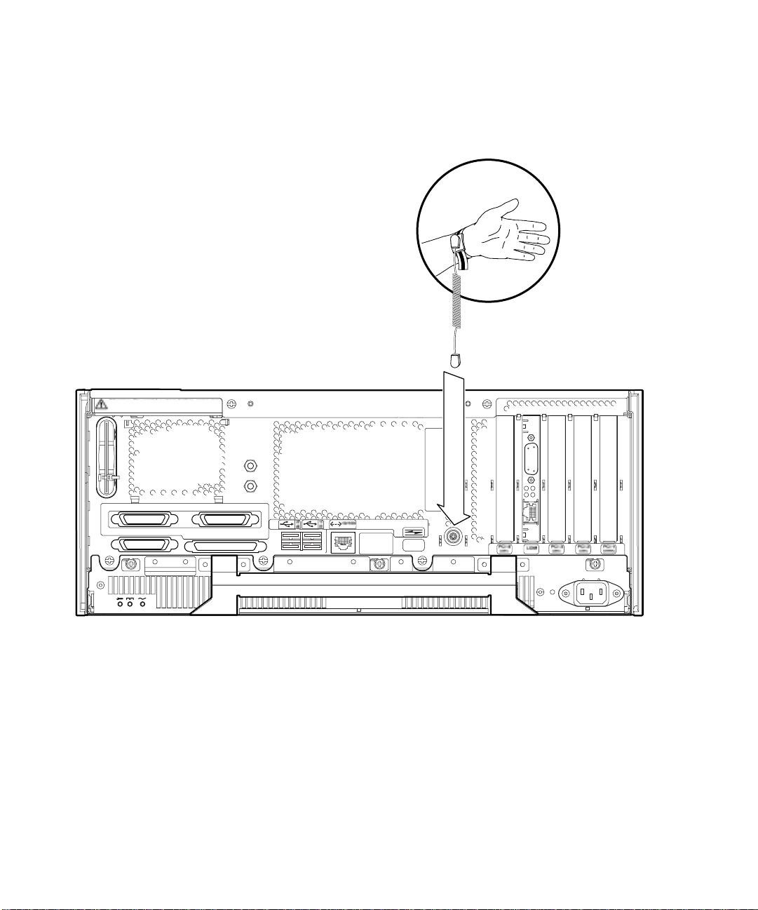
5.5.1 Attaching the Antistatic Wrist Strap
To attach the antistatic wrist strap to the chassis, connect the strap as shown in or
FIGURE 5-3.
Warning: Power off system before removing
or replacing System Configuration Card
FIGURE 5-2 Attaching the Antistatic Wrist Strap to the Rear of the Chassis
5-6 Netra T4 AC100/DC100 Service and System Reference Manual • August 2001

FIGURE 5-3 Attaching the Antistatic Wrist Strap to the Front of the Chassis
Chapter 5 Before Servicing the System 5-7

5.6 Top Access Cover
The top access cover is secured by two captive screws located at the rear of the
system.
FIGURE 5-4 Top Access Cover
Only the PSU, hard disk drives, front fascia and air filter can be accessed without
removing the top cover. If there is sufficient clearance above the unit and it is
mounted on slide rails, you should be able to carry out servicing with the system in
the rack. Otherwise you must remove the system from the rack and service it on a
bench.
Caution – The unit is heavy and requires two people to remove it from and install
it in the rack.
Note – Beryllium copper EMI shielding gaskets are attached to the under surface of
the access cover. Handle the access cover carefully to avoid damaging the gaskets.
5-8 Netra T4 AC100/DC100 Service and System Reference Manual • August 2001

5.6.1 Preparation
Before proceeding to remove the top access cover, carry out the following:
1. Initiate antistatic precautions.
See Section 5.5, “Antistatic Precautions” on page 5-5.
2. If the system is running, shut it down and remove the power.
See Section 5.3.2, “Powering Off the System” on page 5-4.
Caution – Wear an antistatic wrist strap and use an ESD-protected mat when
!
handling components. When servicing or removing system unit components, attach
an ESD Strap to the wrist, then to the connection point provided on the rear of
system, and only then remove the power cord from the system unit. Following this
caution equalizes all electrical potentials with the system unit.
5.6.2 Removing the Top Access Cover
1. Carry out the appropriate steps listed in Section 5.6.1, “Preparation” on page 5-9.
2. Release the two captive Phillips screws from the rear of the access cover.
3. Push the cover away from the front of the chassis to disengage the lugs and lift it off.
When handling the access cover, ensure that you do not damage the EMI shielding
gaskets on the underside of the cover.
5.6.3 Fitting the Top Access Cover
1. Carry out the appropriate steps listed in Section 5.6.1, “Preparation” on page 5-9 as
required.
2. With the fixing screws on the access cover towards the rear of the system chassis,
locate the lugs on the access cover in the slots on the side panels of the system
chassis (see
3. Slide the access cover forward to engage the lugs.
Ensure that the rear of the access cover is flush with the rear of the system chassis.
4. Tighten the two captive Phillips screws to secure the access cover.
FIGURE 5-4).
Chapter 5 Before Servicing the System 5-9

5.7 Front Fascia
The detachable front fascia houses the optional air filter and is fastened to the
system chassis at the bottom edge by two plastic tethers. You need to detach the
fascia completely only to change the filter (to avoid dust from the filter being sucked
back into the system); you can carry out all other procedures by lowering the fascia
and leaving the tethers attached.
Filter Retainer
Filter
Optional
Mesh Screen
FIGURE 5-5 Front Fascia and Filters
5-10 Netra T4 AC100/DC100 Service and System Reference Manual • August 2001
TetherCatch

5.7.1 Removing the Front Fascia
Caution – Exercise care when opening the fascia. You must detach the plastic
locating pegs on the bottom edge of the fascia before lowering it.
1. Pull the fascia away from the top of the chassis not more than 2.5cm (1in.) using
the finger hold in the middle of the fascia.
2. Lift the fascia forward and off the locating pegs on the bottom edge of the fascia.
3. Swing the fascia forward and down so that it hangs on the two plastic tethers.
5.7.1.1 Detaching the Fascia Tethers
4. Squeeze together the sides of each plastic tether and pull it from the system chassis.
5. Similarly, squeeze together the sides of the tether to detach each locating pin in
turn from the retainers on the fascia.
5.7.2 Fitting the Front Fascia
Follow Step 1 through Step 5 if you are refitting the tethers to the fascia, otherwise
start at Step 6.
1. Insert one side of the locating pin on the tether in the retainer on the fascia.
2. Squeeze the sides of the tether together to insert the other locating pin.
3. Repeat Step 1 and Step 2 for the other tether.
4. Insert the other end of one of the tethers in the corresponding slot in system chassis.
If the tether is a tight fit, squeeze the sides of the tether together.
5. Repeat Step 4 for the other tether.
Chapter 5 Before Servicing the System 5-11

6. Swing the fascia up until it is nearly vertical and insert the locating pegs on the
bottom of the fascia in the slots on the system chassis.
Caution – Do not swing the fascia forward once you have inserted the locating pegs
or they may break.
7. Press the top of the fascia forward until the catch on the fascia clicks into place on
the system chassis.
5.8 Air Filter
If required, you can replace the black mesh screen located behind the front fascia
with the optional foam air filter and metal retainer supplied with the system (see
FIGURE 5-5). Clean or replace the filter regularly to maintain the airflow through the
system.
Caution – To ensure that dust is not sucked into the system when you replace the
filter, remove the fascia completely from the system before proceeding.
5.8.1 Removing and Fitting the Mesh Screen
1. Detach the front fascia and place it on a workbench away from the immediate
vicinity of the system.
See Section 5.7.1, “Removing the Front Fascia” on page 5-11.
2. Press the two catches on the mesh screen and lift that side away from the fascia.
3. Carefully disengage the two tabs at the other side from the fascia and lift out the screen.
Take care that you do not damage the plastic locating lugs when you detach the
screen.
4. Continue with Step a or Step b, as required.
a. Replace with a foam filter and retainer as described in Step 4 through Step 6 in
Section 5.8.2, “Replacing the Filter” on page 5-13.
b. Continue from the following step to replace the screen.
5-12 Netra T4 AC100/DC100 Service and System Reference Manual • August 2001

5. Insert the locating tabs one side of the mesh screen into the corresponding slots on the fascia.
6. Carefully swing the other side down until the catches on the screen engage with the fascia.
7. Re-attach the fascia to the system chassis.
See Section 5.7.2, “Fitting the Front Fascia” on page 5-11.
5.8.2 Replacing the Filter
1. If not already removed, detach the front fascia and place it on a workbench away
from the immediate vicinity of the system.
See Section 5.7.1, “Removing the Front Fascia” on page 5-11.
2. Release the two clips securing the filter retainer and lift it from the fascia.
3. Remove the filter and carefully dispose of it.
4. Clean the fascia to remove any remaining dust.
5. Insert a new filter and secure it with the retainer.
6. Re-attach the fascia to the system chassis.
See Section 5.7.2, “Fitting the Front Fascia” on page 5-11.
Chapter 5 Before Servicing the System 5-13

5-14 Netra T4 AC100/DC100 Service and System Reference Manual • August 2001

CHAPTER
6
Power Subassemblies
This chapter describes procedures for removing and replacing the power
subassemblies of the Netra T4 system unit.
The chapter contains the following sections:
■ Section 6.1, “Power Supply Unit” on page 6-1
■ Section 6.2, “Power Distribution Board” on page 6-4
■ Section 6.3, “System Switch and LED Assembly” on page 6-8
Caution – The plug at the end of the AC power cord is the primary means of
disconnection for the Netra T4 AC100 system.
Caution – To isolate the Netra T4 DC100 system, open the circuit breakers in both
negative supply conductors.
6.1 Power Supply Unit
The PSU is located below the motherboard and is accessed from the rear of the
system. The method of removal is the same for the AC and DC PSUs.
6.1.1 Preparation
Before proceeding to remove the PSU, carry out the following:
1. Initiate antistatic precautions.
See Section 5.5, “Antistatic Precautions” on page 5-5.
6-1

2. If the system is running, shut it down and power off the system.
See Section 5.3.2, “Powering Off the System” on page 5-4.
FIGURE 6-1 Power Supply Unit
6.1.2 Removing the PSU
1. Perform the appropriate steps listed in Section 6.1.1, “Preparation” on page 6-1.
2. Remove the power cord from the PSU.
3. Release the three captive Phillips screws (colored purple) located along the top of
the PSU that secure it to the system chassis.
6-2 Netra T4 AC100/DC100 Service and System Reference Manual • August 2001
 Loading...