

Page 1

Netra™T2000 Server
Installation Guide
Sun Microsystems, Inc.
www.sun.com
Part No. 819-5838-10
September 2006, Revision A
Submit comments about this document at: http://www.sun.com/hwdocs/feedback
Page 2
Copyright 2006Sun Microsystems,Inc., 4150 Network Circle, SantaClara, California95054, U.S.A. Allrights reserved.
Sun Microsystems, Inc.has intellectual property rights relating to technologythat isdescribed in thisdocument. Inparticular, and without
limitation, theseintellectual propertyrights may include one ormore ofthe U.S. patentslisted athttp://www.sun.com/patentsand one or
more additional patents orpending patent applications in theU.S. and in other countries.
This documentand the product to which it pertainsare distributedunder licenses restricting theiruse, copying,distribution, and
decompilation. Nopart of the product or of thisdocument may be reproduced in any formby any means without priorwritten authorizationof
Sun andits licensors, if any.
Third-party software, including fonttechnology, iscopyrighted andlicensed from Sun suppliers.
Parts ofthe productmay be derived from BerkeleyBSD systems,licensed from the University ofCalifornia. UNIX is a registered trademark in
the U.S.and in other countries, exclusivelylicensed throughX/Open Company,Ltd.
Sun, SunMicrosystems, theSun logo, Java, AnswerBook2, docs.sun.com,SunStore, Netra,SunInstall, and Solarisare trademarksor registered
trademarks ofSun Microsystems,Inc. in the U.S. andin other countries.
All SPARCtrademarks areused under license and are trademarksor registeredtrademarks ofSPARCInternational, Inc. inthe U.S.and in other
countries. Products bearingSPARCtrademarks arebased upon an architecture developed by SunMicrosystems, Inc.
The OPENLOOK and Sun™ Graphical UserInterface was developed by SunMicrosystems, Inc.for its users and licensees.Sun acknowledges
the pioneeringefforts ofXerox inresearching anddeveloping the concept of visualor graphical user interfaces forthe computer industry.Sun
holds anon-exclusive license from Xeroxto the Xerox GraphicalUser Interface,which license also covers Sun’slicensees who implement OPEN
LOOK GUIsand otherwise comply with Sun’swritten license agreements.
U.S. GovernmentRights—Commercial use.Government users are subject tothe SunMicrosystems, Inc. standard license agreement and
applicable provisions ofthe FAR and its supplements.
DOCUMENTATION IS PROVIDED "AS IS" AND ALL EXPRESS OR IMPLIED CONDITIONS, REPRESENTATIONS AND WARRANTIES,
INCLUDING ANYIMPLIED WARRANTY OFMERCHANTABILITY,FITNESS FOR A PARTICULAR PURPOSE OR NON-INFRINGEMENT,
ARE DISCLAIMED, EXCEPT TO THE EXTENT THAT SUCH DISCLAIMERS ARE HELD TO BE LEGALLY INVALID.
Copyright 2006Sun Microsystems,Inc., 4150 Network Circle, SantaClara, Californie95054, États-Unis. Tous droits réservés.
Sun Microsystems, Inc.possède les droits de propriété intellectuels relatifs à latechnologie décrite dans ce document.En particulier, et sans
limitation, cesdroits depropriété intellectuelspeuvent inclure un ou plusieursdes brevetsaméricains listés sur le site
http://www.sun.com/patents, un oules plusieurs brevets supplémentaires ainsi que lesdemandes de brevet en attente aux lesÉtats-Unis et
dans d’autres pays.
Ce documentet le produit auquel il se rapportesont protégéspar un copyrightet distribuéssous licences, celles-ci en restreignent l’utilisation,
la copie,la distribution, et la décompilation.Aucune partie de ce produit oudocument nepeut être reproduite sous aucune forme, parquelque
moyen quece soit, sans l’autorisation préalableet écrite de Sun etde sesbailleurs de licence,s’il yen a.
Tout logiciel tiers,sa technologie relative aux policesde caractères,comprise, est protégé par un copyright etlicencié par des fournisseurs de
Sun.
Des partiesde ce produit peuvent dériver des systèmesBerkeley BSD licenciés par l’Universitéde Californie. UNIX est unemarque déposée
aux États-Uniset dans d’autres pays, licenciée exclusivement parX/Open Company, Ltd.
Sun, SunMicrosystems, lelogo Sun, Java, AnswerBook2, docs.sun.com,SunStore, Netra,SunInstall, et Solarissont desmarques de fabrique ou
des marques déposéesde Sun Microsystems, Inc. aux États-Unis etdans d’autrespays.
Toutes les marquesSPARCsont utilisées sous licence etsont desmarques de fabrique ou desmarques déposéesde SPARC International, Inc.
aux États-Uniset dans d’autres pays. Les produits portantles marquesSPARCsont basés sur une architecture développée par Sun
Microsystems, Inc.
L’interfaceutilisateur graphiqueOPEN LOOK etSun™ aété développée par Sun Microsystems,Inc. pourses utilisateurs etlicenciés. Sun
reconnaît les efforts depionniers deXerox dans la recherche et le développementdu conceptdes interfaces utilisateurvisuelles ougraphiques
pour l’industrieinformatique. Sun détient une licensenon exclusive de Xerox sur l’interface utilisateurgraphique Xerox,cette licence couvrant
également leslicenciés de Sun implémentant lesinterfaces utilisateur graphiques OPEN LOOKet seconforment en outre aux licencesécrites de
Sun.
LA DOCUMENTATION EST FOURNIE "EN L’ÉTAT" ET TOUTES AUTRES CONDITIONS, DÉCLARATIONS ET GARANTIES EXPRESSES
OU TACITES SONT FORMELLEMENT EXCLUES DANS LA LIMITE DE LA LOI APPLICABLE, Y COMPRIS NOTAMMENT TOUTE
GARANTIE IMPLICITE RELATIVE À LA QUALITÉ MARCHANDE, À L’APTITUDE À UNE UTILISATION PARTICULIÈRE OU À
L’ABSENCE DE CONTREFAÇON.
Please
Recycle
Page 3

Contents
Server Views 1
Server Features 3
Chip-Multitheaded Multicore Processor and Memory Technology 4
Performance Enhancements 5
Preinstalled Solaris Operating System 5
Preloaded Java Enterprise System Software 6
Hardware-Assisted Cryptography 7
Remote Server Management With ALOM 7
System Reliability, Availability, and Serviceability 8
Hot-Swappable Components 8
Power Supply Redundancy 9
Fan Redundancy 9
Environmental Monitoring 9
Error Correction and Parity Checking 10
Fault Management and Predictive Self-Healing 10
Rackmountable Enclosure 11
Tools Needed 13
Shipping Kit Inventory List 13
Installation Overview 14
iii
Page 4

Installing the Air Filter 16
Installing Optional Components 17
Slide Rail Assembly Notes 18
Safety Precautions 20
4-Post Rackmounting Options 22
Hardmounting the Server in a 19-Inch 4-Post Rack 22
▼ To Install a Server With a Hardmount 19-Inch 4-Post Rack 22
Mounting the Server in a Sliding Rail Mount 19-Inch 4-Post Rack 26
▼ To Install a Server With a Sliding Rail Mount in a 19-Inch 4-Post Rack 26
Hardmounting the Server in a 600-mm 4-Post Rack 33
▼ To Install a Server With a Hardmount in a 600-mm 4-Post Rack 33
Installing a Server With a Hardmount in a 19-Inch 4-Post Rack for Use With the
Cable Management Assembly 41
▼ To Install the Slide Rail Assemblies 42
▼ To Install the Cable Management Assembly 47
▼ To Verify the Operation of the Slide Rails and the CMA 50
2-Post Rackmounting Options 56
Hardmounting the Server in a 23-Inch 2-Post Rack 56
▼ To Install a Server With a Hardmount in a 23-Inch 2-Post Rack 56
Hardmounting the Server in a 19-Inch 2-Post Rack 61
▼ To Install a Server With a Hardmount in a 19-Inch 2-Post Rack 61
Data Ports and Cabling Notes 67
Port Locations 67
Cabling Notes 68
Connecting Cables 69
▼ To Connect the Ethernet Network Cables 69
▼ To Connect the SC Serial Management Port 70
▼ To Connect the SC Network Management Port 71
Input Power Cables 72
iv Netra T2000 Server Installation Guide • September 2006
Page 5

TTYA Serial Port 72
USB Ports 73
Alarm Port 74
Managing Cables With the CMA 75
▼ To Open and Close a Cable Clip 75
▼ To Move a Cable Clip 76
Powering On the Server for the First Time 77
▼ To Power On the Server for the First Time 78
Enabling the System Controller Network Management Port 80
Logging Into the System Controller 80
▼ To Log Into the System Controller Using the Serial Management Port 80
▼ To Configure the System Controller Network Management Port 81
▼ To Reset the System Controller 84
▼ To Log Into the System Controller Using the Network Management Port
85
Using the System Controller for Common Operations 86
▼ To Power On the Server 86
▼ To Connect to the System Console 87
▼ To Perform a Normal Server Initialization 87
Booting the Solaris Operating System 89
▼ To Boot the Solaris Operating System 89
▼ To Reset the Server 90
▼ To Power Cycle the Server 90
Contents v
Page 6

vi Netra T2000 Server Installation Guide • September 2006
Page 7

Figures
FIGURE 1-1 Netra T2000 Server Front Panel 1
FIGURE 1-2 Netra T2000 Server Rear Panel 2
FIGURE 1-3 Netra T2000 Server 2
FIGURE 1-5 UltraSPARC T1 Multicore Processor Block Diagram 5
FIGURE 2-1 Finger Holds on Bezel 16
FIGURE 2-2 Installing the Air Filter in the Bezel 17
FIGURE 2-3 Sections of the Slide Rail Assembly 18
FIGURE 2-4 Locating the Locks on the Slide Rail Assembly 19
FIGURE 3-1 Contents of the Hardmount 19-Inch 4-Post Kit 23
FIGURE 3-2 Securing the Hardmount Brackets to the Server 24
FIGURE 3-3 Attaching the Rear Mount Support Brackets 25
FIGURE 3-4 Securing the Front of the Server to the Rack 25
FIGURE 3-5 Securing the Rear of the Server to the Rack 26
FIGURE 3-6 Contents of the Sliding Rail 19-Inch 4-Post Kit 27
FIGURE 3-7 Securing the Hardmount Bracket to the Server 28
FIGURE 3-8 Dismantling the Slide 29
FIGURE 3-9 Fixing the Glides to the Server Chassis 29
FIGURE 3-10 Securing the Brackets to the Rack 30
FIGURE 3-11 Securing the Slide to the Brackets 31
FIGURE 3-12 Sliding the Server Into the Rack 32
vii
Page 8

FIGURE 3-13 Securing the Front of the Server to the Rack 32
FIGURE 3-14 Contents of the Hardmount 600-mm 4-Post Kit 34
FIGURE 3-15 Adjustable Rail Screws 35
FIGURE 3-16 Securing the Front of the Adjustable Rails to the Rack 36
FIGURE 3-17 Securing the Rear of the Adjustable Rails to the Rack 37
FIGURE 3-18 Installing the Rear Flange Onto the Adjustable Rail 38
FIGURE 3-19 Securing the Side Rails to the Server 39
FIGURE 3-20 Sliding the Server Onto the Adjustable Rails 39
FIGURE 3-21 Securing the Rear of the Server to the Rear Flanges 40
FIGURE 3-22 Securing the Front of the Server to the Front of the Rack 41
FIGURE 3-23 Unlocking the Slide Rail Assembly 42
FIGURE 3-24 Location of the Mounting Bracket Release Button 43
FIGURE 3-25 Unlocking the Slide Rail Middle Section 43
FIGURE 3-26 Attaching a Mounting Bracket to the Chassis 44
FIGURE 3-27 Mounting a Slide Rail 45
FIGURE 3-28 Adjusting the Distance Between the Slide Rails 46
FIGURE 3-29 Mounting the Chassis on the Slide Rails 47
FIGURE 3-30 Inserting the CMA Rail Extension Into the Rear of the Left Slide Rail 48
FIGURE 3-31 Mounting the Inner CMA Connector 49
FIGURE 3-32 Attaching the Outer CMA Connector 49
FIGURE 3-33 Mounting the Left Side of the Rail 50
FIGURE 3-34 Unlocking the Slide Rail Assembly 51
FIGURE 3-35 Unlocking the Slide Rail Lever Stops 52
FIGURE 3-36 Slide Rail Release Button 52
FIGURE 4-1 Contents of the Hardmount 23-Inch 2-Post Kit 57
FIGURE 4-2 Securing the Side Brackets to the Side of the Server 58
FIGURE 4-3 Installing the Rail Guides in the Rack 58
FIGURE 4-4 Installing and Securing the Server in the 2-Post Rack 59
FIGURE 4-5 Installing a Screw on the Middle Rack Position on the Rear Plate 60
FIGURE 4-6 Installing the Rear Plate to the Side Bracket 60
viii Netra T2000 Server Installation Guide • September 2006
Page 9

FIGURE 4-7 Securing the Rear Plate to the Back of the Post 61
FIGURE 4-8 Contents of the Hardmount 19-Inch 2-Post Kit 62
FIGURE 4-9 Securing the Side Brackets to the Side of the Server 63
FIGURE 4-10 Installing and Securing the Server in the 2-Post Rack 63
FIGURE 4-11 Installing Screws on the Optimum Rack Position on the Rear Plate 64
FIGURE 4-12 Installing the Rear Plate to the Side Bracket 65
FIGURE 4-13 Securing the Rear Plate to the Rack 66
FIGURE 5-1 Rear Panel Features 68
FIGURE 5-2 Ethernet Network Connections 70
FIGURE 5-3 System Controller Serial Connection 71
FIGURE 5-4 System Controller Network Connection 72
FIGURE 5-5 Serial Port 73
FIGURE 5-6 USB Ports 74
FIGURE 5-7 Alarm Port 74
FIGURE 5-8 Opening a Cable Clip 75
FIGURE 5-9 Removing a Cable Clip 76
FIGURE 5-10 Mounting or Moving a Cable Clip 76
FIGURE 6-1 Rear Panel Power Connectors 78
Figures ix
Page 10

x Netra T2000 Server Installation Guide • September 2006
Page 11

Tables
TABLE 4 Server Features 3
TABLE 3-1 Optional Rackmount Kits 22
TABLE 3-2 19-inch 4-Post Rackmount Screw Kit Contents 23
TABLE 3-3 Sliding Rail 19-inch 4-Post Rackmount Screw Kit Contents 27
TABLE 3-4 Hardmount 600 mm 4-Post Rackmount Screw Kit Contents 34
TABLE 4-1 Optional Rackmount Kits 56
TABLE 4-2 Hardmount 23-Inch 2-Post Rackmount Screw Kit Contents 57
TABLE 4-3 Hardmount 19-Inch 2-Post Rackmount Screw Kit Contents 62
TABLE 6-1 Sample Configuration Parameter Setting 83
TABLE 6-2 Map of Devices, OpenBoot Path Names, and Locations 88
TABLE A-1 Server Software Configuration Worksheet 93
xi
Page 12

xii Netra T2000 Server Installation Guide • September 2006
Page 13

Preface
The Netra T2000 Server Installation Guide provides procedures and information to
assist you to install the server into a rack. This document is written for technicians,
system administrators, authorized service providers (ASPs), and users who have
experience installing and configuring hardware.
How This Document Is Organized
Chapter 1 provides an overview of the features of the Netra™ T2000 server.
Chapter 2 provides background information for the server installation procedures.
Chapter 3 provides instructions for installing the server in an open 4-post rack or a
closed cabinet.
Chapter 4 provides instructions for installing the server in an open 2-post rack.
Chapter 5 provides instructions for cabling the server.
Chapter 6 includes instructions for booting the server and for enabling the system
controller network management port.
Appendix A provides a software configuration worksheet.
xiii
Page 14

Using UNIX Commands
This document might not contain information about basic UNIX®commands and
procedures such as shutting down the system, booting the system, and configuring
devices. Refer to the following for this information:
■ Software documentation that you received with your system
■ Solaris™ Operating System documentation, which is at:
http://docs.sun.com
Shell Prompts
Shell Prompt
C shell machine-name%
C shell superuser machine-name#
Bourne shell and Korn shell $
Bourne shell and Korn shell superuser #
Typographic Conventions
Typeface
AaBbCc123 The names of commands, files,
AaBbCc123 What you type, when contrasted
AaBbCc123 Book titles, new words or terms,
xiv Netra T2000 Server Installation Guide • September 2006
*
Meaning Examples
and directories; on-screen
computer output
with on-screen computer output
words to be emphasized.
Replace command-line variables
with real names or values.
Edit your.login file.
Use ls -a to list all files.
% You have mail.
su
%
Password:
Read Chapter 6 in the User’s Guide.
These are called class options.
You must be superuser to do this.
To delete a file, type rm filename.
Page 15

* The settings on your browser might differ from these settings.
Related Documentation
Application Title Part Number Format Location
Administration Netra T2000 Server Administration Guide 819-5837 PDF Online
Installation Netra T2000 Server Installation Guide 819-5838 PDF Online
Updates Netra T2000 Server Product Notes 819-5840 PDF Online
Service Netra T2000 Server Service Manual 819-5841 PDF Online
Planning Netra T2000 Server Site Planning Notes 819-5842 PDF Online
Compliance Netra T2000 Server Safety and Compliance Guide 819-5843 PDF Online
Documentation Netra T2000 Server Getting Started Guide 819-5844 Printed
PDF
Reference ALOM CMT 1.2 Guide 819-3250 PDF Online
Shipping kit
Online
The documents listed as online are available at:
http://www.sun.com/products-n-solutions/hardware/docs/
Documentation, Support, and Training
Sun Function URL
Documentation http://www.sun.com/documentation/
Support http://www.sun.com/support/
Training http://www.sun.com/training/
Preface xv
Page 16
Third-Party Web Sites
Sun™ is not responsible for the availability of third-party web sites mentioned in
this document. Sun does not endorse and is not responsible or liable for any content,
advertising, products, or other materials that are available on or through such sites
or resources. Sun will not be responsible or liable for any actual or alleged damage
or loss caused by or in connection with the use of or reliance on any such content,
goods, or services that are available on or through such sites or resources.
Sun Welcomes Your Comments
Sun is interested in improving its documentation and welcomes your comments and
suggestions. You can submit your comments by going to:
http://www.sun.com/hwdocs/feedback
Please include the title and part number of your document with your feedback:
Netra T2000 Server Installation Guide, part number 819-5838-10
xvi Netra T2000 Server Installation Guide • September 2006
Page 17
CHAPTER
1
Netra T2000 Overview
This chapter provides an overview of the features of the Netra T2000 server. The
following topics are covered:
■ “Server Views” on page 1
■ “Server Features” on page 3
■ “System Reliability, Availability, and Serviceability” on page 8
■ “Fault Management and Predictive Self-Healing” on page 10
■ “Rackmountable Enclosure” on page 11
Server Views
The following figures show the physical characteristics of the server.
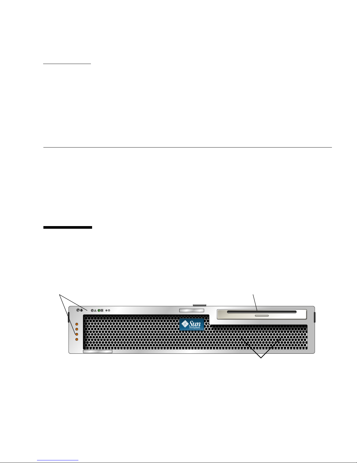
Indicators and buttons
FIGURE 1-1 Netra T2000 Server Front Panel
Removable media drive
Hard drives (behind bezel)
1
Page 18
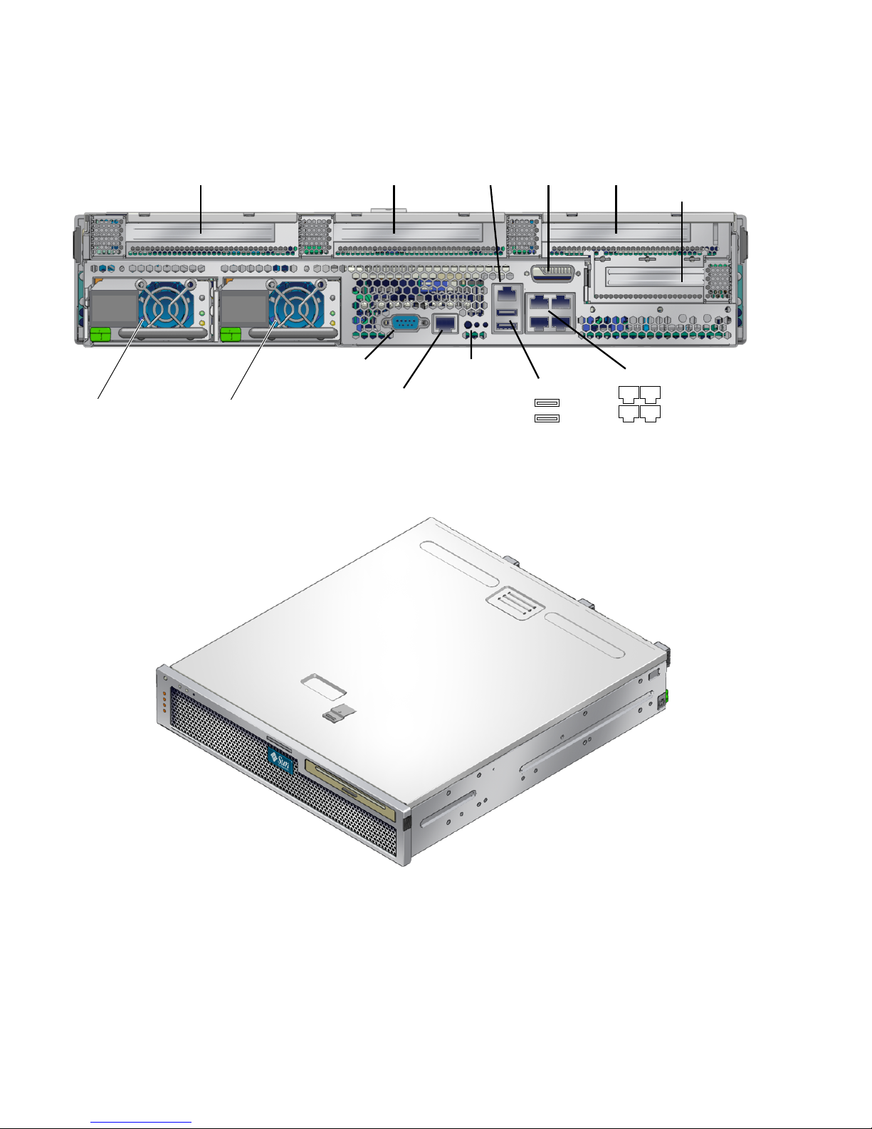
PCI-X slot 0 PCI-X slot 1 PCI-X slot 2
port
SC NET MGT
Alarm
port
PCI-E slot 0
TTYA serial
Power supply 0 Power supply 1
FIGURE 1-2 Netra T2000 Server Rear Panel
port
SC serial mgt
port
Indicators
USB ports
1
0
GBE ports
2
3
0 1
FIGURE 1-3 Netra T2000 Server
2 Netra T2000 Server Installation Guide • September 2006
Page 19

Server Features
The server is a high-performance, entry-level server that is widely scalable and
extremely reliable. The server delivers a variety of options to meet specific business
needs. The server has the following features:
TABLE 4 Server Features
Feature Description
Processor 1 UltraSPARC®T1 multicore processor (4, 6, or 8 cores)
Memory 16 slots that can be populated with one of the following types of
DDR2 DIMMS:
• 256 MB (4 GB maximum)
• 512 MB (8 GB maximum)
• 1 GB (16 GB maximum)
• 2 GB (32 GB maximum)
Ethernet ports 4 ports, 10/100/1000 Mb
Internal hard
drives
Other internal
peripherals
Alarm 1 Telco alarm
USB ports 2 USB 2.0 connectors
Cooling 3 high-power fans for processor, memory DIMM, and PCI card
PCI interfaces • 1 PCI-Express (PCI-Ex8) low-profile expansion slot
Power 2 dual-redundant, hot-swappable AC/DC power supply units
Remote
management
Firmware Firmware comprising:
2 SFF SAS hard drives
1 Removable media drive
cooling; and 2 low-power fans for hard drive and removable media
drive cooling
• 3 PCI-X 133 slots (2 full-length cards and 1 half-length card)
(PSUs)
ALOM system controller with a serial port and a 10/100 Mb
Ethernet port
• OpenBoot™ PROM for system settings and power-on self test
(POST) support
• ALOM for remote management
Cryptography Hardware-assisted cyptographic acceleration
Operating system Solaris 10 3/05 HW2 Operating System preinstalled on disk 0
Chapter 1 Netra T2000 Overview 3
Page 20

TABLE 4 Server Features (Continued)
Feature Description
Other software Java™ Enterprise System with a 90-day trial licence
Chip-Multitheaded Multicore Processor and
Memory Technology
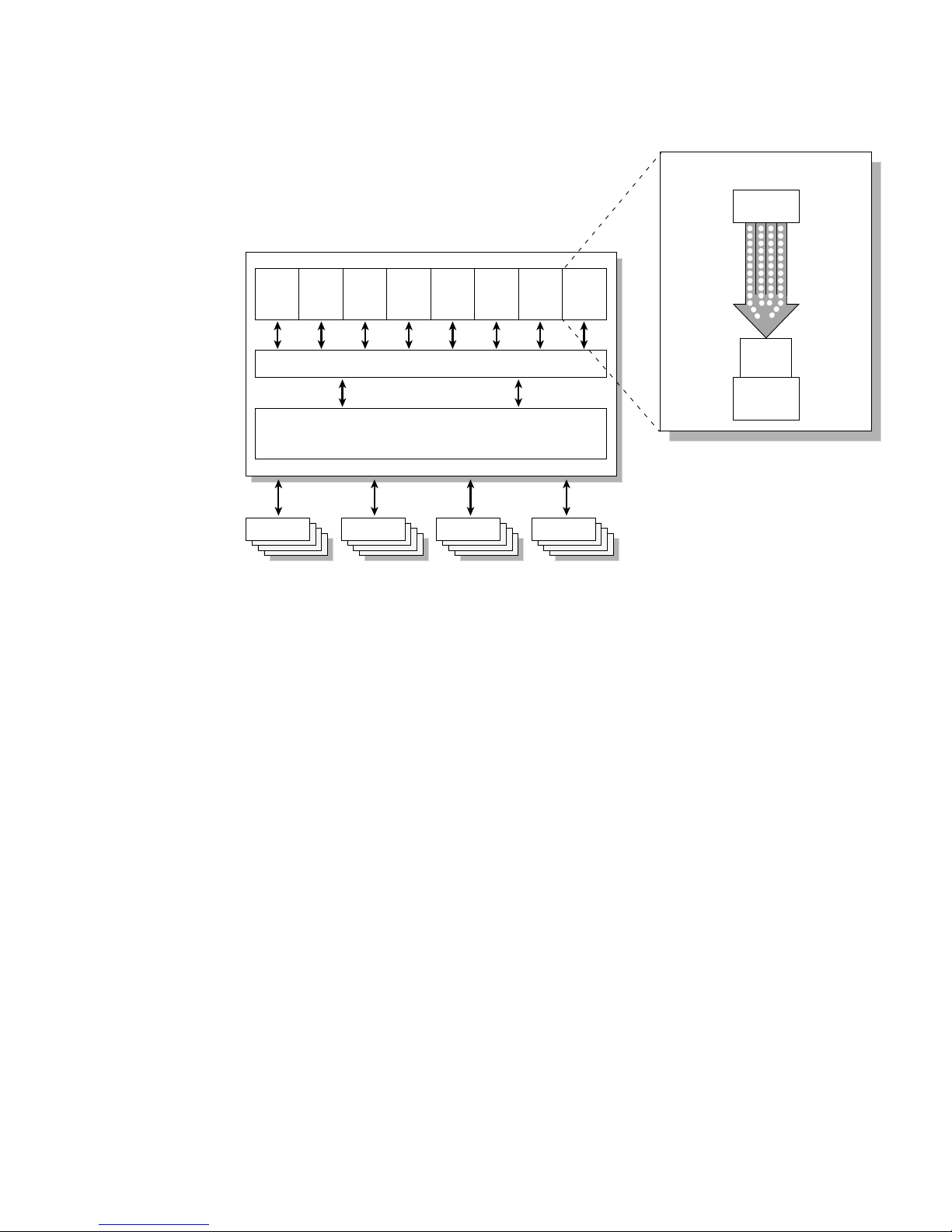
The UltraSPARC T1 multicore processor is the basis of the server. The UltraSPARC
T1 processor is based on chip-multithreading (CMT) technology that is optimized for
highly threaded transactional processing. The UltraSPARC T1 processor improves
throughput while using less power and dissipating less heat than conventional
processor designs.
Depending on the model purchased, the processor has four, six, or eight UltraSPARC
cores. Each core equates to a 64-bit execution pipeline capable of running four
threads. The result is that the 8-core processor handles up to 32 active threads
concurrently.
Additional processor components, such as L1 cache, L2 cache, memory access
crossbar, DDR2 memory controllers, and a JBus I/O interface have been carefully
tuned for optimal performance. See
FIGURE 1-5.
4 Netra T2000 Server Installation Guide • September 2006
Page 21
Multithreaded pipe
Instruction
cache
SPARC
SPARC
SPARC
SPARC
SPARC
SPARC
SPARC
SPARC
core
core
core
core
core
core
core
core
Crossbar
Shared L2 cache
DRAM DRAM DRAM DRAM
FIGURE 1-5 UltraSPARC T1 Multicore Processor Block Diagram
4 threads
Integer
pipeline
Data
cache
Performance Enhancements
The server introduces several new technologies with its sun4v architecture and
multithreaded UltraSPARC T1 multicore processor.
Some of these enhancements are:
■ Large page optimization
■ Reduction on TLB misses
■ Optimized block copy
Preinstalled Solaris Operating System
The server is preinstalled with the Solaris 10 HW 3/05 Operating System (Solaris
OS), and offers the following Solaris OS features:
■ Stability, high performance, scalability, and precision of a mature 64-bit operating
system
■ Support for over 12,000 leading technical and business applications
Chapter 1 Netra T2000 Overview 5
Page 22

■ Solaris containers – Isolate software applications and services using flexible,
software-defined boundaries
■ DTrace – A comprehensive dynamic tracing framework for tuning applications
and troubleshooting systemic problems in real time
■ Predictive self-healing – Capability that automatically diagnoses, isolates, and
recovers from many hardware and application faults
■ Security – Advanced security features designed to protect the enterprise at
multiple levels
■ Network performance – Completely rewritten TCP/IP stack dramatically
improves the performance and scalability of your networked services
Preloaded Java Enterprise System Software
The server is preinstalled with Java Enterprise System software and includes a free
90-day evaluation license for the following Java Enterprise System software
applications:
■ Access Manager – A security foundation that helps manage secure access to an
enterprises’ web applications by offering single sign-on (SSO) as well as enabling
federation across trusted networks.
■ Application Server – Provides a Java 2 Platform, Enterprise Edition (J2EE™
platform) 1.4 compatible platform for developing and delivering server-side Java
applications and web services.
■ Calendar Server – A web-based tool that facilitates team collaboration by enabling
users to manage and coordinate appointments, events, tasks, and resources.
■ Cluster software – Delivers high availability to enterprise system applications.
■ Directory Server – User-management infrastructure for enterprises that manage
high volumes of user information by providing a centralized repository for
storing and managing user profiles and access privileges, as well as application
and network resource information.
■ Directory Proxy Server – Provides secure firewall-like services for the Directory
Server.
■ Instant Messaging – A standards-based, real-time communication and
collaboration application.
■ Message Queue – An enterprise-level message server using a standards-based
(JMS) messaging solution.
■ Messaging Server – A high-performance, highly secure messaging platform that
provides security features that help ensure the integrity of communications.
■ Portal Server – Provides portal services that identify users through centralized
identity services using roles, and policies.
6 Netra T2000 Server Installation Guide • September 2006
Page 23

■ Web Server – A secure, reliable, easy-to-use web server designed for medium and
large business applications.
To continue the benefits of the Java Enterprise System, you can buy a subscription
license for a Java Enterprise System Suite, or a combination of Java System Suites.
Hardware-Assisted Cryptography
The UltraSPARC T1 multicore processor provides hardware-assisted acceleration of
RSA and DSA cryptographic operations. The Solaris 10 Operating System provides
the multithreaded device driver (ncp device driver) that supports the hardwareassisted cryptography.
Remote Server Management With ALOM
The Sun Advanced Lights Out Manager (ALOM) feature is a system controller that
enables you to interact with your server over a network, or by using a dedicated
serial port for connection to a terminal or terminal server. ALOM provides a
command-line interface to remotely manage and troubleshoot geographically
distributed or physically inaccessible machines. ALOM runs independently of the
server and continues to function when the server operating system goes offline or
when the server is powered off.
The ALOM 4v software is preinstalled as firmware, and initializes as soon as you
apply power to the server. You can customize ALOM to work with your particular
installation. You can configure ALOM to send email alerts of hardware failures,
hardware warnings, and other events related to the server or to ALOM. ALOM
monitors the following server components:
■ CPU temperature conditions
■ Disk drive status
■ Enclosure thermal conditions
■ Fan speed and status
■ Power supply status
■ Voltage conditions
For more information about using ALOM, see the server administration guide.
Chapter 1 Netra T2000 Overview 7
Page 24
System Reliability, Availability, and
Serviceability
Reliability, availability, and serviceability (RAS) are aspects of a server’s design that
affect its ability to operate continuously and to minimize the time necessary to
service the server.
■ Reliability – a server’s ability to operate continuously without failures and to
maintain data integrity.
■ Availability – the ability of a server to recover to an operational state after a
failure, with minimal impact.
■ Serviceability – the time it takes to restore a server to service following a system
failure.
Together, reliability, availability, and serviceability features provide for near
continuous server operation.
To deliver high levels of reliability, availability, and serviceability, the server offers
the following features:
■ Hot-swappable hard drives
■ Redundant, hot-swappable power supplies (two)
■ Redundant fan units (three) for processor, memory, and PCI card cooling, and
redundant fan units (two) for HD and DVD drives
■ Environmental monitoring
■ Error detection and correction for improved data integrity
■ Easy access for most component replacements
For more information about using RAS features, refer to the server administration
guide.
Hot-Swappable Components
The server hardware supports hot-swapping of the chassis-mounted hard drives and
power supplies. By using the proper software commands, you can install or remove
these components while the server is running. Hot-swap technology significantly
increases the server’s serviceability and availability by providing the ability to
replace hard drives and power supplies without service disruption.
8 Netra T2000 Server Installation Guide • September 2006
Page 25

Power Supply Redundancy
The server features two redundant hot-swappable power supplies, enabling the
server to continue operating should one of the power supplies fail or if one power
source fails.
Fan Redundancy
The server has two drive specific fans that work in conjunction with the two power
supply fans to provide cooling for the internal disk drives. Additionally, there are
three fans to cool the motherboard components.
Environmental Monitoring
The server features an environmental monitoring subsystem protects the server and
its components against:
■ Extreme temperatures
■ Lack of adequate airflow through the server
■ Power supply failures
■ Hardware faults
Temperature sensors are located throughout the server to monitor the ambient
temperature of the server and internal components. The software and hardware
ensure that the temperatures within the enclosure do not exceed predetermined safe
operating levels. If the temperature observed by a sensor falls below a lowtemperature threshold or rises above a high-temperature threshold, the monitoring
subsystem software lights the amber Service Required LEDs on the front and rear
panel. If the temperature condition persists and reaches a critical threshold, the
server initiates a graceful system shutdown. If the ALOM fails, backup sensors
protect the server from serious damage, by initiating a forced hardware shutdown.
All error and warning messages are sent to the system console and logged in the
ALOM console log file. Service Required LEDs remain lit after an automatic system
shutdown to aid in problem diagnosis.
The monitoring subsystem is also designed to detect fan failures. The system
features integral power supply fans, as well as one PCI fan and three blowers. If the
PCI fan or blower fails, the monitoring subsystem detects the failure and generates
an error message to the system console, logs the message in the
/var/adm/messages file, and lights the Service Required LEDs.
Chapter 1 Netra T2000 Overview 9
Page 26
The power subsystem is monitored in a similar fashion and any fault is indicated at
the front and rear panel LEDs. Additionally, LEDs located on each power supply
light to indicate failures.
Error Correction and Parity Checking
The UltraSPARC T1 multicore processor provides parity protection on its internal
cache memories, including tag parity and data parity on the D-cache and I-cache.
The internal 3MB L2 cache has parity protection on the tags, and ECC protection on
the data.
Advanced ECC, also called chipkill, corrects up to 4-bits in error on nibble
boundaries, as long as they are all in the same DRAM. If a DRAM fails, the DIMM
continues to function.
Fault Management and Predictive SelfHealing
The server features the latest fault management technologies. With the Solaris 10
Operating System (OS), Sun is introducing a new architecture for building and
deploying systems and services capable of Predictive Self-Healing. Self-healing
technology enables Sun servers to accurately predict component failures and
mitigate many serious problems before they actually occur. This technology is
incorporated into both the hardware and software of the server.
At the heart of the predictive self-healing capabilities is the Solaris Fault Manager, a
new service that receives data relating to hardware and software errors, and
automatically and silently diagnoses the underlying problem. Once a problem is
diagnosed, a set of agents automatically responds by logging the event, and if
necessary, takes the faulty component offline. By automatically diagnosing
problems, business-critical applications and essential system services can continue
uninterrupted in the event of software failures, or major hardware component
failures.
10 Netra T2000 Server Installation Guide • September 2006
Page 27

Rackmountable Enclosure
The server uses a space-saving 2U-high rackmountable enclosure that can be
installed into a variety of industry standard racks.
Chapter 1 Netra T2000 Overview 11
Page 28

12 Netra T2000 Server Installation Guide • September 2006
Page 29

CHAPTER
2
Preparing for Installation
This chapter provides background information about the server installation
procedures.
This chapter contains these topics:
■ “Tools Needed” on page 13
■ “Shipping Kit Inventory List” on page 13
■ “Installation Overview” on page 14
■ “Installing the Air Filter” on page 16
■ “Installing Optional Components” on page 17
■ “Slide Rail Assembly Notes” on page 18
■ “Safety Precautions” on page 20
Tools Needed
■ Phillips screwdrivers
■ ESD mat and grounding strap
Shipping Kit Inventory List
Standard components of the server are installed at the factory. However, if you
ordered options such as a PCI card and monitor, these are shipped to you separately.
Note – Inspect the shipping cartons for evidence of physical damage. If a shipping
carton appears damaged, request that the carrier’s agent be present when the carton
is opened. Keep all contents and packing material for the agent’s inspection.
13
Page 30

Verify that you have received all the parts of your server.
■ Server chassis
■ 19-inch, 4-post rackmount kit and a slide rail assembly
■ Package of mounting screws and nuts in assorted sizes to fit various types of
racks and cabinets
■ Miscellaneous hardware, cables, connectors, etc
■ Cable management arm with six preinstalled cable clips
■ Manufacturer’s instruction sheet for the cable management arm
■ Any optional components that were ordered with the server
Installation Overview
This installation guide provides procedures that must be performed in the following
order.
1. Verify that you have received all of the components that ship with your server, as
described in the preceding section.
2. Gather configuration information for your server. See your system administrator
for specific details, including these parameters:
■ Netmask
■ IP address for the system controller
■ Gateway IP address
See “Software Configuration Worksheet” on page 93.
3. Remove the shipping insert from the bezel and install the air filter. See “Installing
the Air Filter” on page 16.
4. Install any optional Sun components into your server before rackmounting. See
the server service manual for instructions.
5. Mount the server into a rack or cabinet. See “4-Post Rackmounting Options” on
page 22 and “2-Post Rackmounting Options” on page 56.
Note – In the rest of this manual, the term rack means either an open rack or a
closed cabinet.
6. Connect the chassis grounding cable.
7. Connect the serial, network, and all other data cables to the server. See “Cabling
the Server” on page 67.
14 Netra T2000 Server Installation Guide • September 2006
Page 31
8. Connect the server to a serial terminal or a terminal emulator (PC or workstation)
to display system messages. See “Powering On the Server for the First Time” on
page 77.
Tip – The serial terminal or a terminal emulator should be connected, powered on,
and ready before you connect the power cables, or you will not see the system
messages.
9. Assemble and connect the input power cables to the server and examine the
display for any error messages. See “Powering On the Server for the First Time”
on page 77.
Caution – There is a potential for electric shock if the server and related equipment
are not properly grounded.
Note – The system controller (SC) runs on the 3.3v standby voltage. As soon as
power is connected to the server, the system controller immediately powers on, runs
diagnostics, and initializes the ALOM firmware.
10. After the system controller boots, access the ALOM command-line interface
through the serial management port. See “To Log Into the System Controller
Using the Serial Management Port” on page 80.
11. Configure the SC network addresses. See “To Log Into the System Controller
Using the Network Management Port” on page 85.
Note – The SC network management port is not operational until you configure
network settings for the system controller (through the SC serial management port).
12. Enable the new configuration by resetting the system controller. See “To Reset
the System Controller” on page 84.
13. Confirm that the Ethernet connection is attached to the server.
14. Check whether the rotary switch is in the Normal position.
15. Power on the server from a keyboard using the ALOM software. See “To Power
On the Server” on page 86.
16. Configure the Solaris OS. See “Booting the Solaris Operating System” on page 89.
The Solaris OS is preinstalled on the server. When you power on, you are
automatically guided through the Solaris OS configuration procedure.
Chapter 2 Preparing for Installation 15
Page 32
17. Install any required patches to the server.
Refer to the server product notes for a list of the required patches.
18. Load additional software from the optional Solaris media kit.
The Solaris media kit (sold separately) includes several CDs containing software
to help you operate, configure, and administer your server. Refer to the
documentation provided with the media kit for a complete listing of included
software and detailed installation instructions.
Installing the Air Filter
The server ships with a protective shipping insert located between the bezel and the
front panel. You must remove this protective insert and replace it with an air filter
before powering on the server.
Caution – Failure to remove the shipping insert from the front bezel can block the
air from flowing through the server, which would seriously damage the server
components.
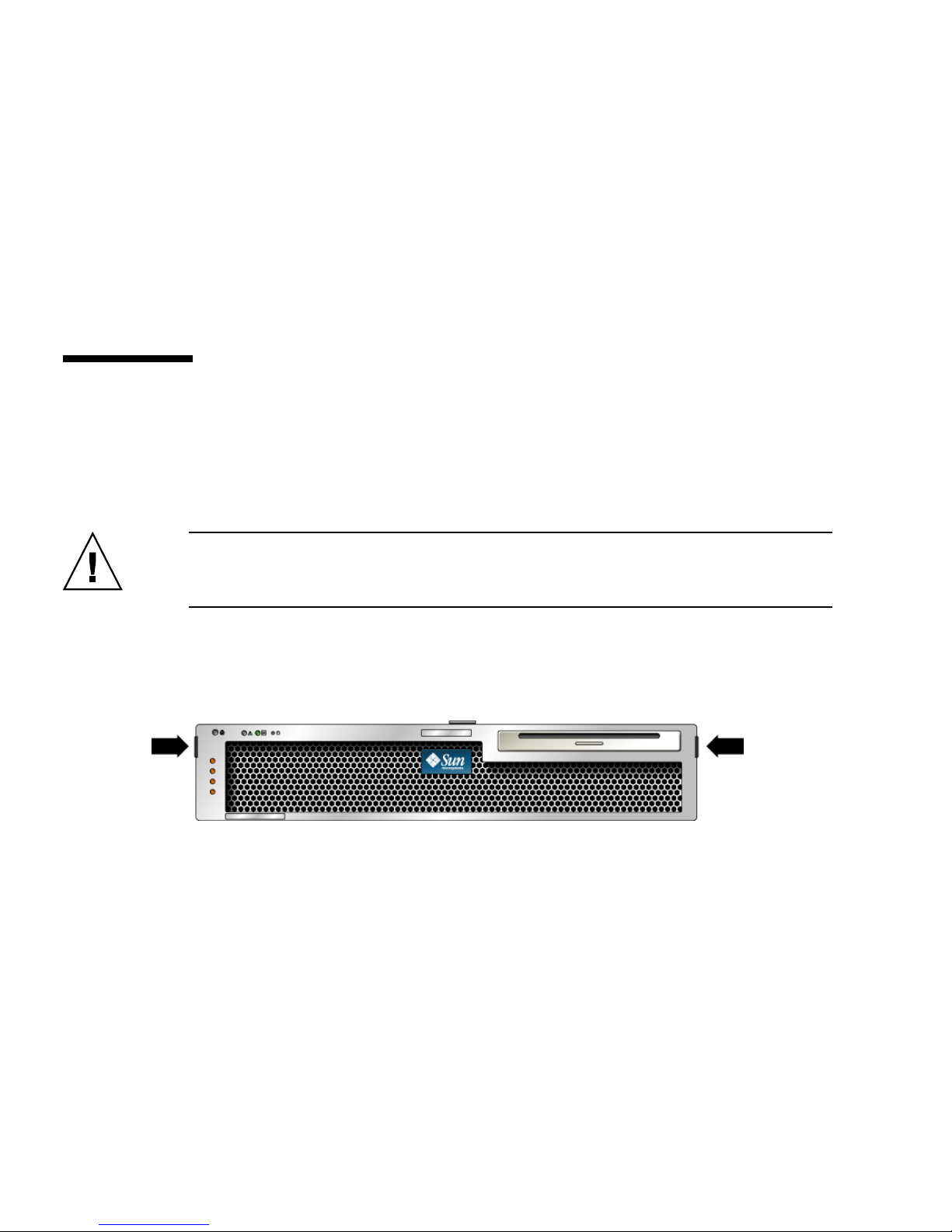
1. Grip the bezel at the two finger holds and rotate it down to its open position
FIGURE 2-1).
(
FIGURE 2-1 Finger Holds on Bezel
2. Carefully remove the shipping insert from the inside of the bezel.
3. Obtain the air filter that shipped with your server.
4. Snap the new air filter into place in the bezel (
FIGURE 2-2).
16 Netra T2000 Server Installation Guide • September 2006
Page 33
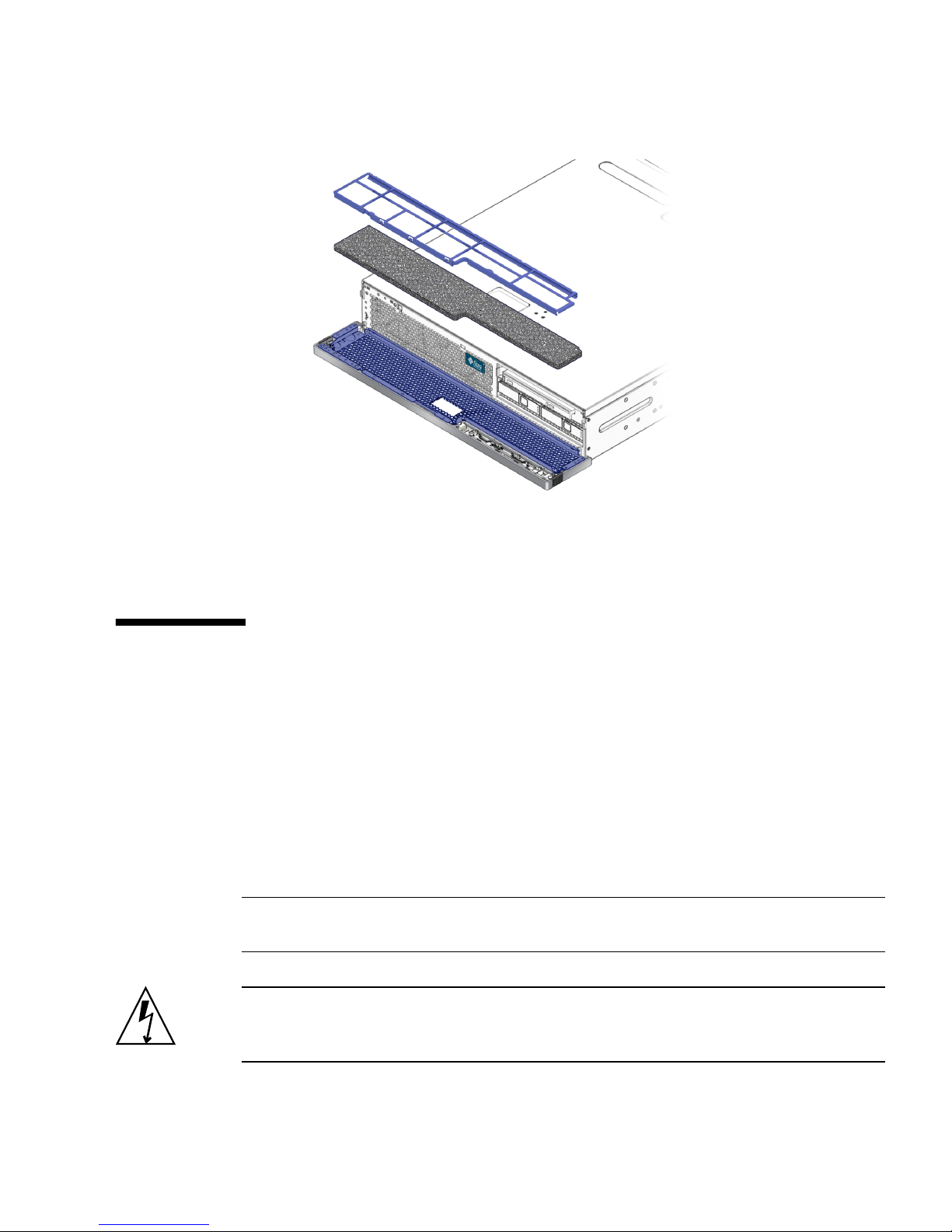
FIGURE 2-2 Installing the Air Filter in the Bezel
5. Close the bezel.
Installing Optional Components
The standard components of the server are installed at the factory. However, if you
ordered options such as additional memory or a PCI card, these will be shipped
separately. If possible, install these components prior to installing the server in a
rack.
Install any optional components shipped with your server.
If you ordered options that are not factory-installed, see the server service manual
for installation instructions.
Note – All internal components except disk drives must be installed by qualified
service technicians only.
Caution – To protect electronic components from electrostatic damage, which can
permanently disable the server or require repair by Sun service technicians, note the
following guidelines.
Chapter 2 Preparing for Installation 17
Page 34
■ Place components on an antistatic surface, such as a Sun antistatic discharge mat,
M
an antistatic bag, or a disposable antistatic mat.
■ Always wear an antistatic wrist strap connected to a metal surface on the chassis
when you work on server components.
Refer to the server service manual for the list of optional components.
Note – The optional component list might be updated at any time. Refer to the
SunStore™ web site (http://store.sun.com) for the most current list of server
supported components.
Slide Rail Assembly Notes
The rackmount kit has two slide rail assemblies. A slide rail assembly can be installed
on either the right or left side of the rack.
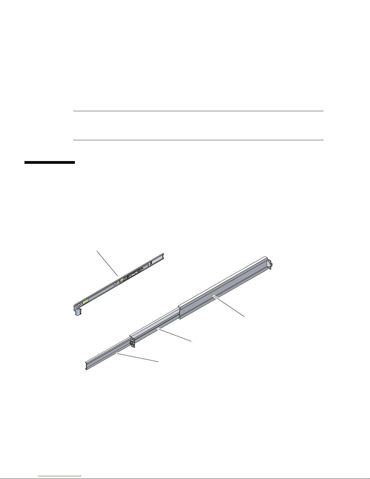
Each slide rail assembly consists of a three-section slide rail and a removable
mounting bracket (
FIGURE 2-3).
ounting bracket
Rear section
Middle section
Front section
FIGURE 2-3 Sections of the Slide Rail Assembly
18 Netra T2000 Server Installation Guide • September 2006
Page 35
■ The front, middle, and rear sections form the slide rail. The middle and rear sections
have holes for mounting screws and adjust to fit rack depths from 24 in. (61 cm)
to 36.5 in. (93 cm). The front section can be extended to enable movement of the
server out of the rack.
■ The removable mounting bracket slides 14 in. (36 cm) out of the slide rail, then
locks in place. If you unlock the mounting bracket at this point, it slides an
additional 12 in. (30 cm) before separating from the slide rail. You can then mount
the mounting bracket to the right or left side of the chassis.
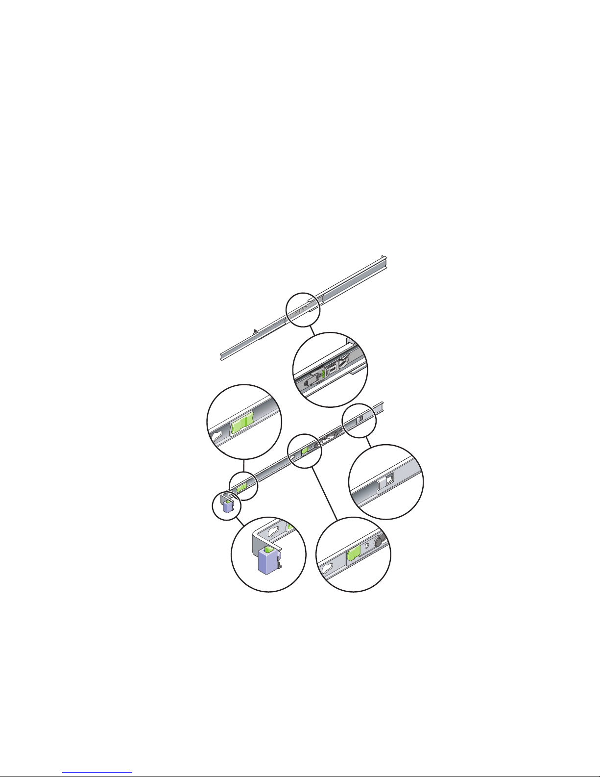
■ Note that there are a total of five locks (FIGURE 2-4) in a slide rail assembly. Four
are on the mounting bracket. One lock is on the front section of the slide rail.
FIGURE 2-4 Locating the Locks on the Slide Rail Assembly
Chapter 2 Preparing for Installation 19
Page 36
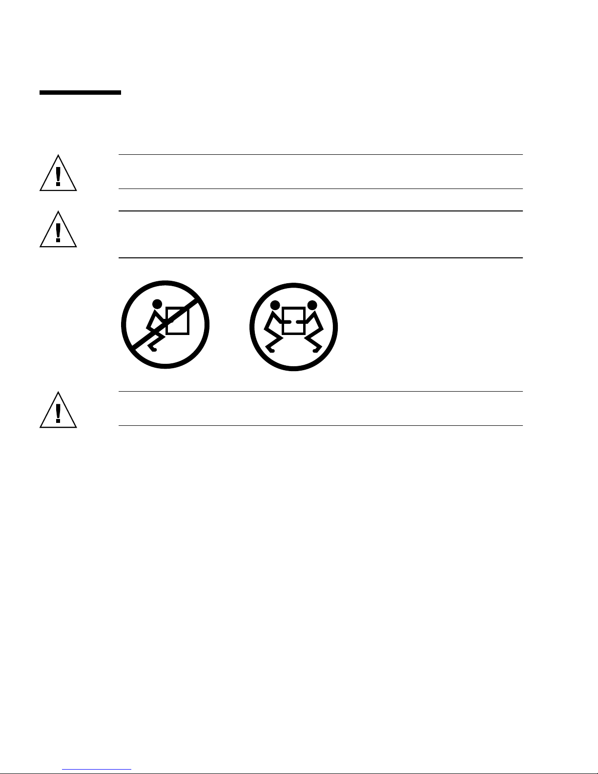
Safety Precautions
Caution – Deploy the antitilt bar on the cabinet or rack before beginning an
installation.
Caution – The server weighs approximately 40 lb (18 kg). Two people are required
to lift and mount the server into a rack enclosure when using the procedures in this
chapter.
Caution – When completing a two-person procedure, always communicate your
intentions clearly before, during, and after each step to minimize confusion.
20 Netra T2000 Server Installation Guide • September 2006
Page 37

CHAPTER
3
Mounting the Server Into a 4-Post
Rack
This chapter provides instructions for installing the server in an open 4-post rack or
closed cabinet.
This chapter contains the following sections:
■ “4-Post Rackmounting Options” on page 22
■ “Hardmounting the Server in a 19-Inch 4-Post Rack” on page 22
■ “Mounting the Server in a Sliding Rail Mount 19-Inch 4-Post Rack” on page 26
■ “Hardmounting the Server in a 600-mm 4-Post Rack” on page 33
■ “Installing a Server With a Hardmount in a 19-Inch 4-Post Rack for Use With the
Cable Management Assembly” on page 41
Note – References to left and right are from your viewpoint as you face either the
front or rear of the equipment.
Caution – The server is heavy. Two people are required to lift and mount the server
into a rack enclosure when following the procedures in this chapter.
21
Page 38

4-Post Rackmounting Options
The server ships with a 19-inch, 4-post hardmount rack kit (see “To Install a Server
With a Hardmount 19-Inch 4-Post Rack” on page 22 for installation instructions).
TABLE 3-1 lists three additional 4-post rackmount kit options that can be ordered from
Sun. This chapter provides installation instructions for these rackmount kit options.
TABLE 3-1 Optional Rackmount Kits
Mounting Kit Installation Instructions
19-inch, 4-post slide mount kit for
600–800 mm cabinet depths
600 mm x 600 mm rackmount kit “To Install a Server With a Hardmount in a 600-mm
19-inch, 4-post slide rail kit for 800–
1000 mm cabinet depths with cable
management assembly
“To Install a Server With a Sliding Rail Mount in a
19-Inch 4-Post Rack” on page 26
4-Post Rack” on page 33
“Installing a Server With a Hardmount in a 19-Inch
4-Post Rack for Use With the Cable Management
Assembly” on page 41
Note – If you have more than six DC-powered servers in the same rack, you might
exceed Telcordia NEBS EMI limits.
Hardmounting the Server in a 19-Inch 4Post Rack
▼ To Install a Server With a Hardmount 19-Inch 4-
Post Rack
The hardmount kit for a 19-inch 4-post rack consists of:
■ Two hardmount brackets
■ Two rear mount support brackets
■ Two rear mount flanges
■ Bag of screws
22 Netra T2000 Server Installation Guide • September 2006
Page 39
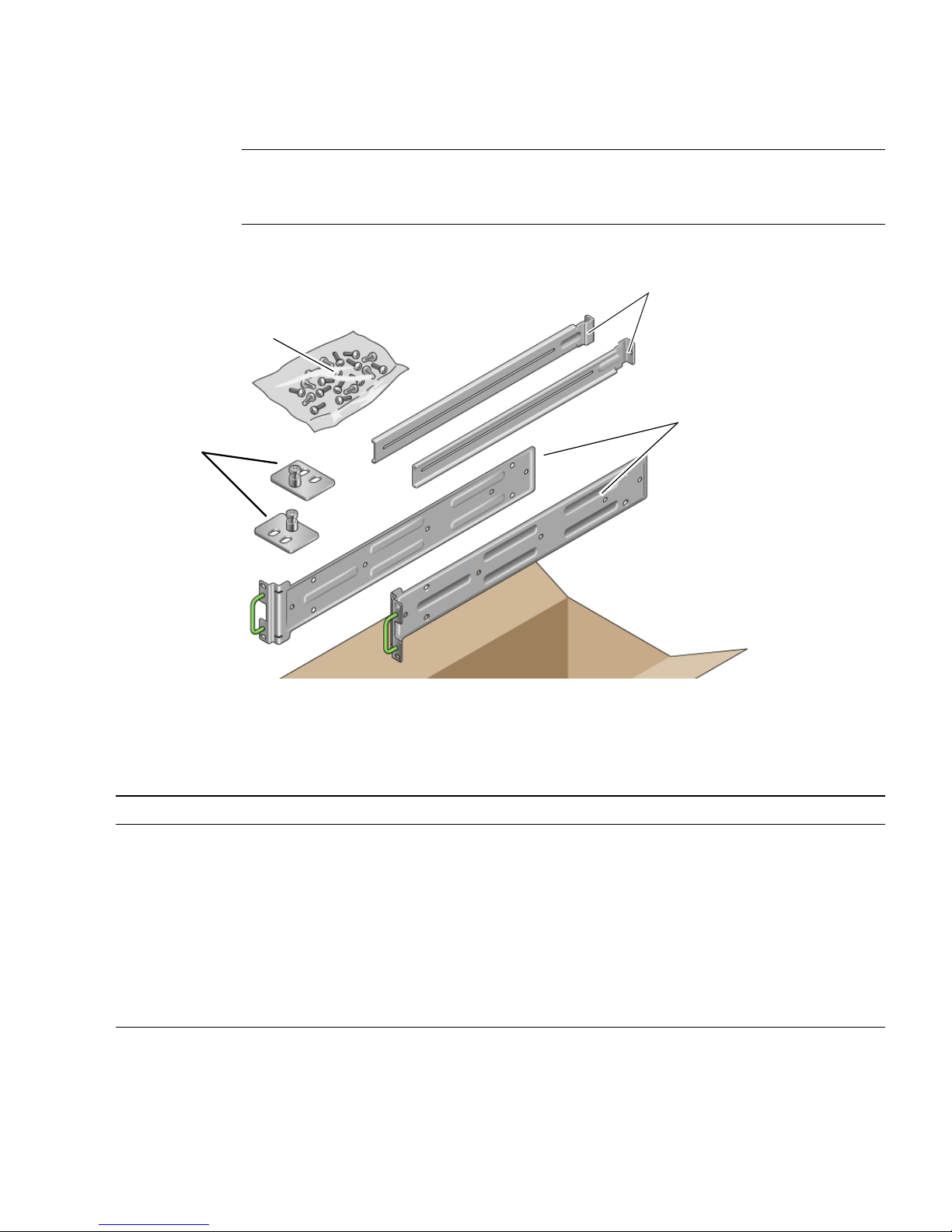
Rear mount
flanges
Note – The front-to-back rail spacing must be at least 460 mm (18.11 in.) and not
more than 715 mm (28.15 in.) from the outside face of the front rail to the outside
face of the back rail.
Rear mount support brackets
Screws
Hardmount brackets
FIGURE 3-1 Contents of the Hardmount 19-Inch 4-Post Kit
TABLE 3-2 19-inch 4-Post Rackmount Screw Kit Contents
Number Description Where Used
10 M5 x 8 mm Phillips flathead screws 8 for hardmount brackets, 2 extra
10 M4 x 0.5 mm x 5 mm Phillips panhead screws 4-6 for rear mount brackets, 6-4 extra
10 M5 x 12.7 mm screws 10 for rack, if appropriate
10 M6 x 13 mm screws 10 for rack, if appropriate
9 M6 square clip nuts 9 for rack, if appropriate
12 10-32 x 0.5 in. combo head screws 12 for rack, if appropriate
12 12-24 x 0.5 in. combo head screws 12 for rack, if appropriate
1. Get the hardmount brackets from the rack kit (FIGURE 3-1).
Chapter 3 Mounting the Server Into a 4-Post Rack 23
Page 40
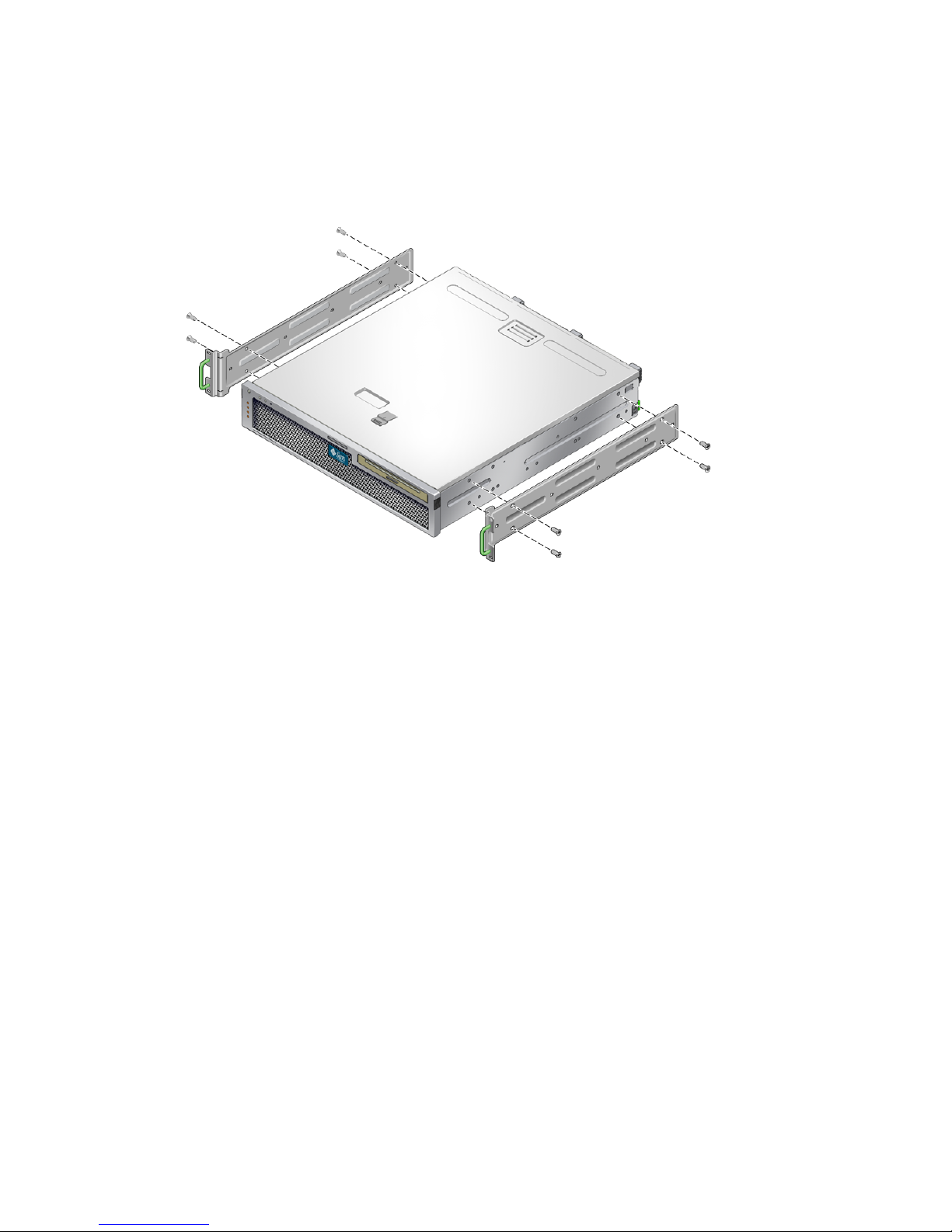
2. Use four of the supplied M5 × 8 mm flathead Phillips screws to secure each of the
hardmount brackets to the sides of the server (
FIGURE 3-2 Securing the Hardmount Brackets to the Server
FIGURE 3-2).
3. Measure the depth of the rack.
4. Get the two rear mount support brackets from the rack kit (
FIGURE 3-1).
5. Install the rear mount support brackets at the rear of the server, extending the rear
mount support brackets to the measured depth of the rack (
FIGURE 3-3).
Use two to three of the supplied M4 × 0.5 × 5 mm panhead Phillips screws for each
bracket, depending on the rack depth.
24 Netra T2000 Server Installation Guide • September 2006
Page 41
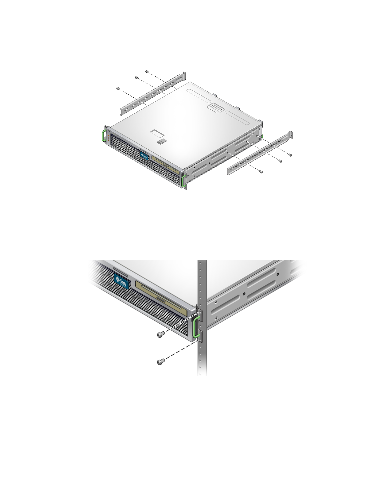
FIGURE 3-3 Attaching the Rear Mount Support Brackets
6. Lift the server to the desired location in the rack.
7. Using two screws per side, secure the front of the hardmount brackets attached to
the sides of the server to the front of the rack (
FIGURE 3-4).
FIGURE 3-4 Securing the Front of the Server to the Rack
8. Get the two rear mount flanges from the rack kit (FIGURE 3-1).
9. Using two screws for each rear mount support bracket, secure the rear mount
support brackets to the rear of the rack (
FIGURE 3-5).
Chapter 3 Mounting the Server Into a 4-Post Rack 25
Page 42
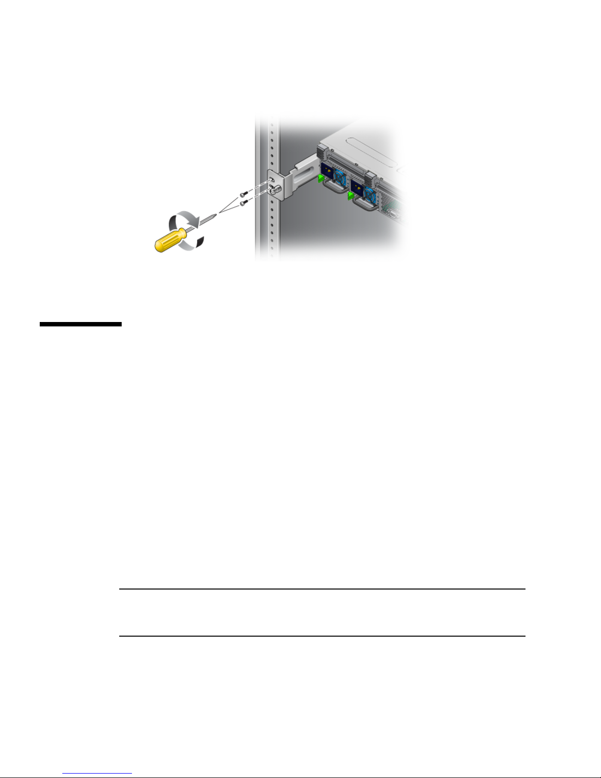
FIGURE 3-5 Securing the Rear of the Server to the Rack
Mounting the Server in a Sliding Rail
Mount 19-Inch 4-Post Rack
▼ To Install a Server With a Sliding Rail Mount in
a 19-Inch 4-Post Rack
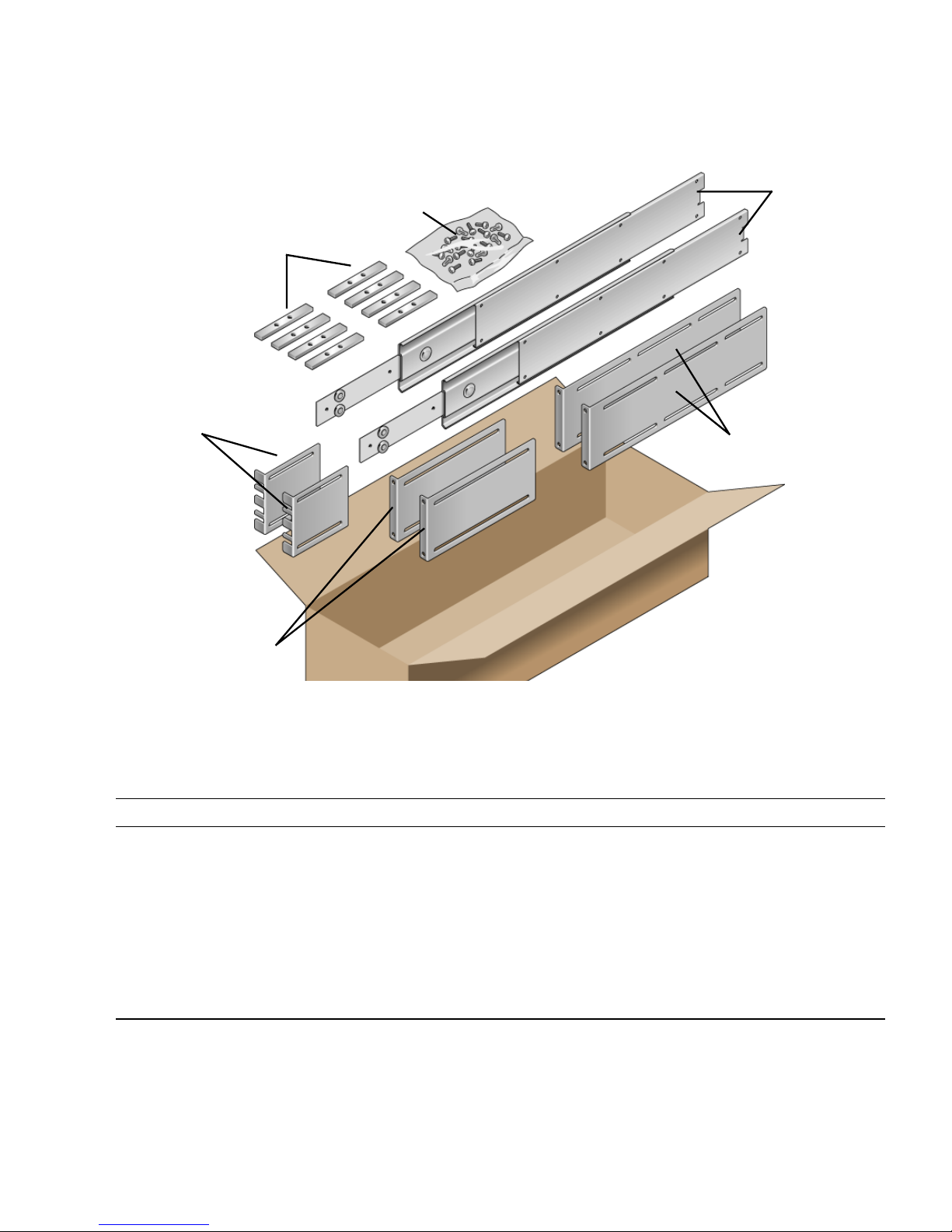
The sliding rail mount kit for a 19-inch 4-post rack consists of:
■ Two 19-inch 4-post Telco slide assemblies
■ Two short brackets
■ Two long brackets
■ Four M6 and four 10–32 threaded strips
■ Two extension brackets
■ Bag of screws
Note – The front-to-back rail spacing must be at least 392 mm (15.43 in.) and not
more than 863.6 mm (34 in.) from the outside face of the front rail to the outside face
of the back rail.
You also need the hardmount brackets from the standard rackmount kit that came
with the server (
26 Netra T2000 Server Installation Guide • September 2006
FIGURE 3-1).
Page 43
Threaded strips
Screws
Telco slide
assemblies
Short brackets
Long brackets
FIGURE 3-6 Contents of the Sliding Rail 19-Inch 4-Post Kit
TABLE 3-3 Sliding Rail 19-inch 4-Post Rackmount Screw Kit Contents
Number Description Where Used
10 M4 x 0.5 mm x 5 mm Phillips panhead screws 8 for glides, 2 extra
Extension brackets
10 M6 brass collar screws 4 for short brackets, 4 for long brackets, 2 extra
8 M5 panhead screws, nuts, plain washers and
star washers
10 M5 x 12.7 mm screws 10 for rack, if appropriate
12 M6 x 13 mm screws 10 for rack, if appropriate
9 M6 square clip nuts 9 for rack, if appropriate
8 for slides
Chapter 3 Mounting the Server Into a 4-Post Rack 27
Page 44
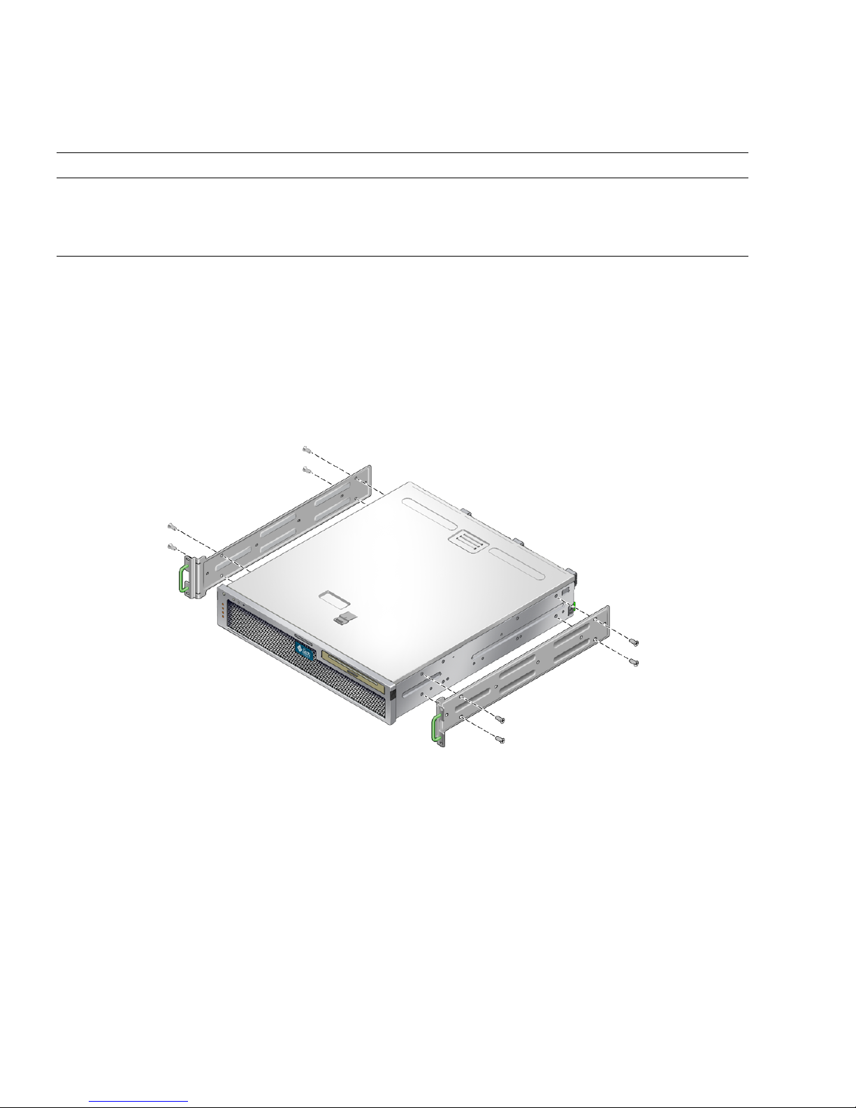
TABLE 3-3 Sliding Rail 19-inch 4-Post Rackmount Screw Kit Contents (Continued)
Number Description Where Used
10 10–32 collar screws 4 short, 4 long, 2 extra 8 for racks with 10-32 holes, if appropriate
12 10-32 x 0.5 in. combo head screws 12 for rack, if appropriate
12 12-24 x 0.5 in. combo head screws 12 for rack, if appropriate
1. Get the hardmount brackets and M5 × 8 mm flathead Phillips screws from the
standard rack kit (
FIGURE 3-1).
These hardmount brackets and screws are shipped with the standard server ship kit,
not as part of the sliding rail 19-inch 4-post rackmount ship kit.
2. Use four of the supplied M5 × 8 mm flathead Phillips screws to secure each of the
hardmount brackets to the sides of the server (
FIGURE 3-7).
FIGURE 3-7 Securing the Hardmount Bracket to the Server
3. Get the Telco slide assemblies from the rack kit (FIGURE 3-6).
4. Press in the button on each slide and pull the glide completely out of the slide
(
FIGURE 3-8).
28 Netra T2000 Server Installation Guide • September 2006
Page 45
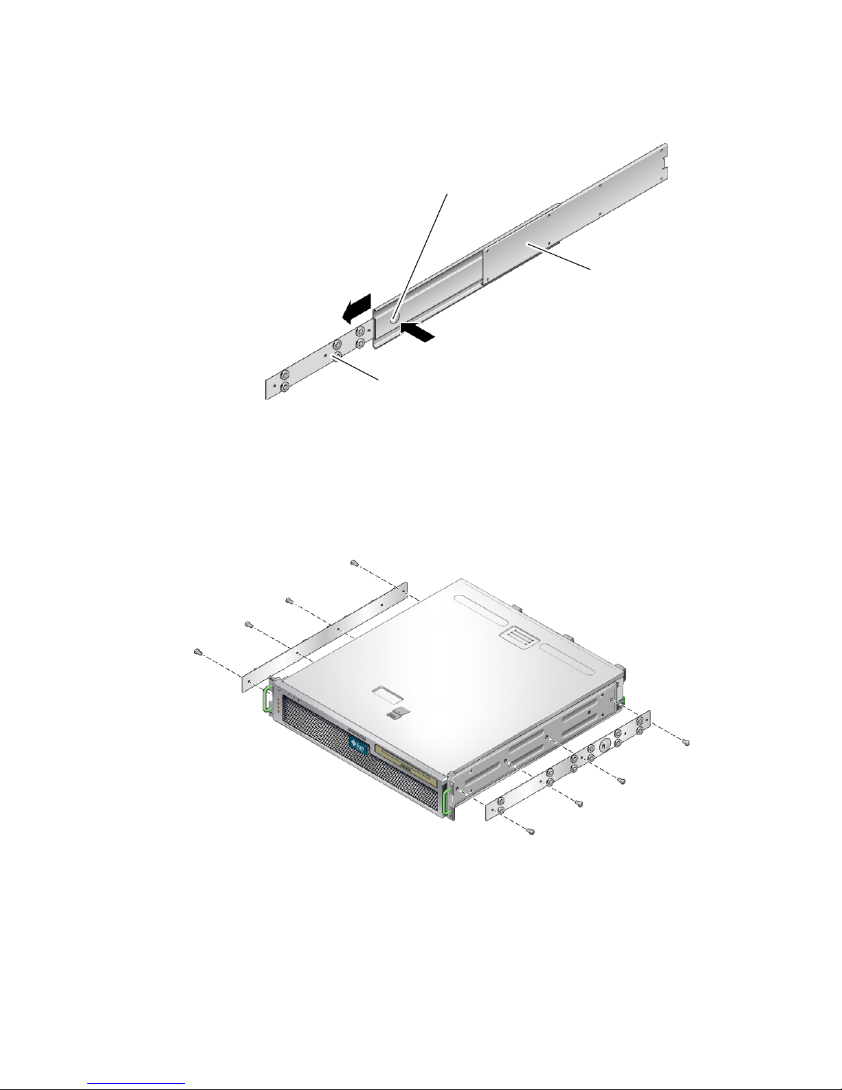
Button
Slide (in two parts)
Glide
FIGURE 3-8 Dismantling the Slide
5. Using eight of the M4 × 0.5 × 5 mm panhead Phillips screws from the rackmount
kit (four for each side), screw each glide to the side of the server chassis
(
FIGURE 3-9).
FIGURE 3-9 Fixing the Glides to the Server Chassis
6. Get the short brackets and long brackets from the rackmount kit (FIGURE 3-6).
Chapter 3 Mounting the Server Into a 4-Post Rack 29
Page 46
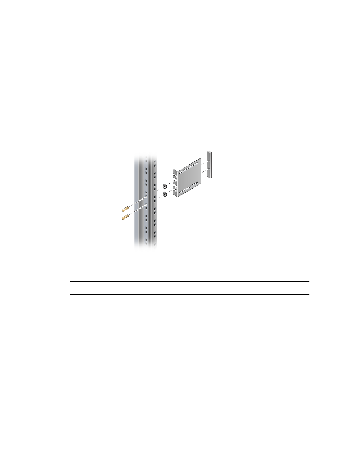
7. Lift each short bracket to the desired position at the front of the rack and attach a
short bracket to each of the front rack uprights (
FIGURE 3-10).
Use two of the brass M6 collar screws and M6 cage nuts (if required), and one
threaded strip, to secure each bracket (
FIGURE 3-10).
8. Lift each long bracket to the desired position at the rear of the rack and attach a
long bracket to each of the rear rack uprights (
FIGURE 3-10).
To secure each bracket, use two of the brass M6 collar screws and M6 cage nuts (if
required) and one threaded strip, exactly as you did for the front rack uprights in the
previous step.
FIGURE 3-10 Securing the Brackets to the Rack
Note – If your rack has 10–32 holes, use the 10–32 collar screws and 10–32 threaded strips.
9. Extend a slide to line up the access holes with the front screw holes.
10. Secure the slide onto the short and long brackets at the front and rear of the rack
(
FIGURE 3-11).
Use the M5 panhead screws from the inside, and the M5 nuts, plain washers, and
star washers from the outside. Use extension brackets instead of the long brackets if
the dimension is greater than 665 mm
30 Netra T2000 Server Installation Guide • September 2006
.
Page 47
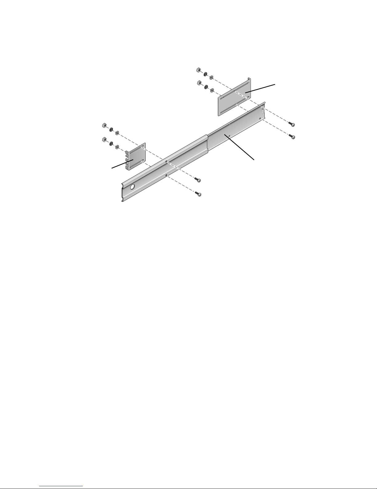
Long bracket
Short bracket
FIGURE 3-11 Securing the Slide to the Brackets
Slide
11. Repeat Step 9 and Step 10 for the slide on the other side of the rack.
12. Push the slides completely into the assembly on each side of the rack and release
the stop catches.
13. Align the glides attached to the server with the slide assemblies in the rack.
You might find that there is too much or too little room between the two slides
mounted in the rack, consequently the glides attached to the server might not align
correctly with the slides in the rack. If either situation occurs, loosen the M6 collar
screws and cage nuts on the long and short brackets (Step 7 and Step 8), move them
inward or outward to the appropriate points, then tighten them again.
14. Push in the slide buttons and slide the server all the way into the rack enclosure
(
FIGURE 3-12).
Chapter 3 Mounting the Server Into a 4-Post Rack 31
Page 48
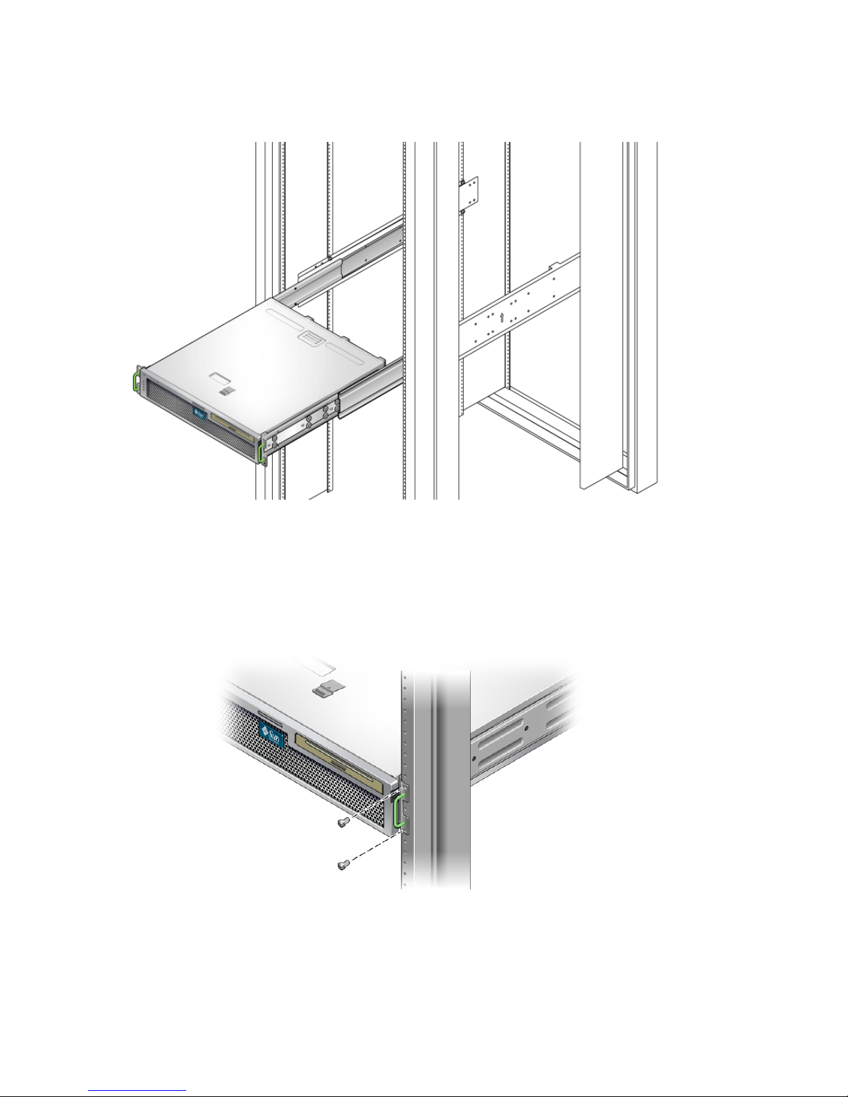
FIGURE 3-12 Sliding the Server Into the Rack
15. Using two screws per side, secure the front of the hardmount brackets that are
attached to the sides of the server to the front of the rack (
FIGURE 3-13).
The size of the screws varies, depending on your particular rack.
FIGURE 3-13 Securing the Front of the Server to the Rack
32 Netra T2000 Server Installation Guide • September 2006
Page 49

Hardmounting the Server in a 600-mm 4Post Rack
▼ To Install a Server With a Hardmount in a 600-
mm 4-Post Rack
The hardmount kit for a 600 mm 4-post rack consists of:
■ Two adjustable rails
■ Two side rails
■ Two rear flanges
■ Bag of screws
Note – The front-to-back rail spacing must be at least 392 mm (15.43 in.) and not
more than 504 mm (19.84 in.) from the outside face of the front rail to the outside
face of the back rail.
Chapter 3 Mounting the Server Into a 4-Post Rack 33
Page 50
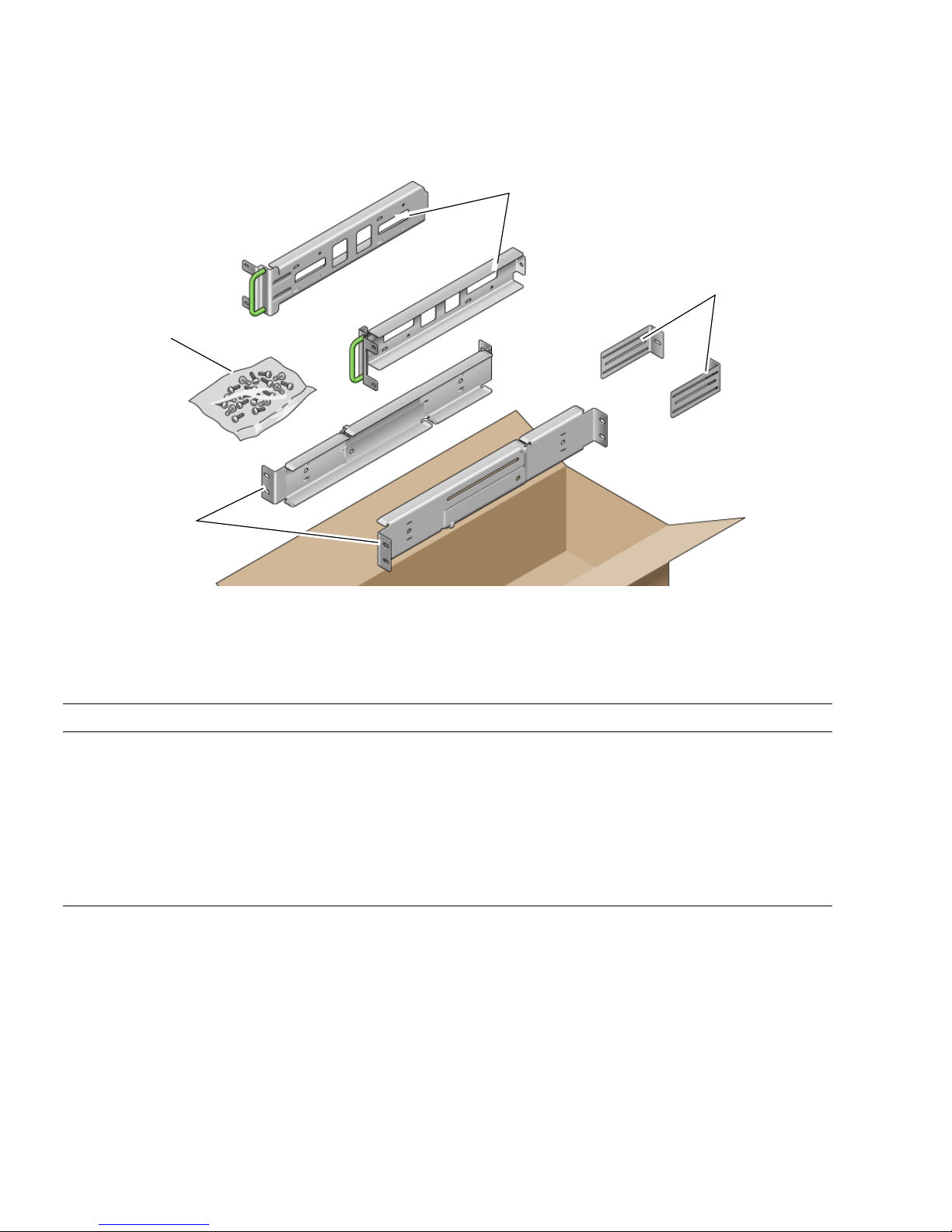
Screws
Adjustable rails
Side rails
Rear flanges
FIGURE 3-14 Contents of the Hardmount 600-mm 4-Post Kit
TABLE 3-4 Hardmount 600 mm 4-Post Rackmount Screw Kit Contents
Number Description Where Used
12 M5 x 10 SEM screws 8 for side rails, 4 for rear flanges
10 M5 x 12.7 mm screws 10 for rack, if appropriate
10 M6 x 13 mm screws 10 for rack, if appropriate
9 M6 square clip nuts 9 for rack, if appropriate
12 10-32 x 0.5 in. combo head screws 12 for rack, if appropriate
12 12-24 x 0.5 in. combo head screws 12 for rack, if appropriate
1. Get the adjustable rails from the rack kit (FIGURE 3-14).
2. Loosen the two screws at the middle of each adjustable rail so that you can extend
the adjustable rail (
34 Netra T2000 Server Installation Guide • September 2006
FIGURE 3-15).
Page 51
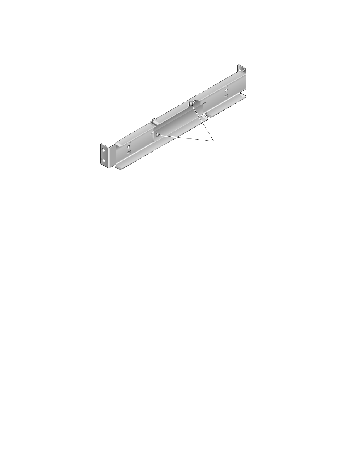
Adjustable rail screws
FIGURE 3-15 Adjustable Rail Screws
3. Lift one of the adjustable rails to the desired location in the rack. Using two
screws, secure the front of the rail in the rack (
FIGURE 3-16).
Chapter 3 Mounting the Server Into a 4-Post Rack 35
Page 52
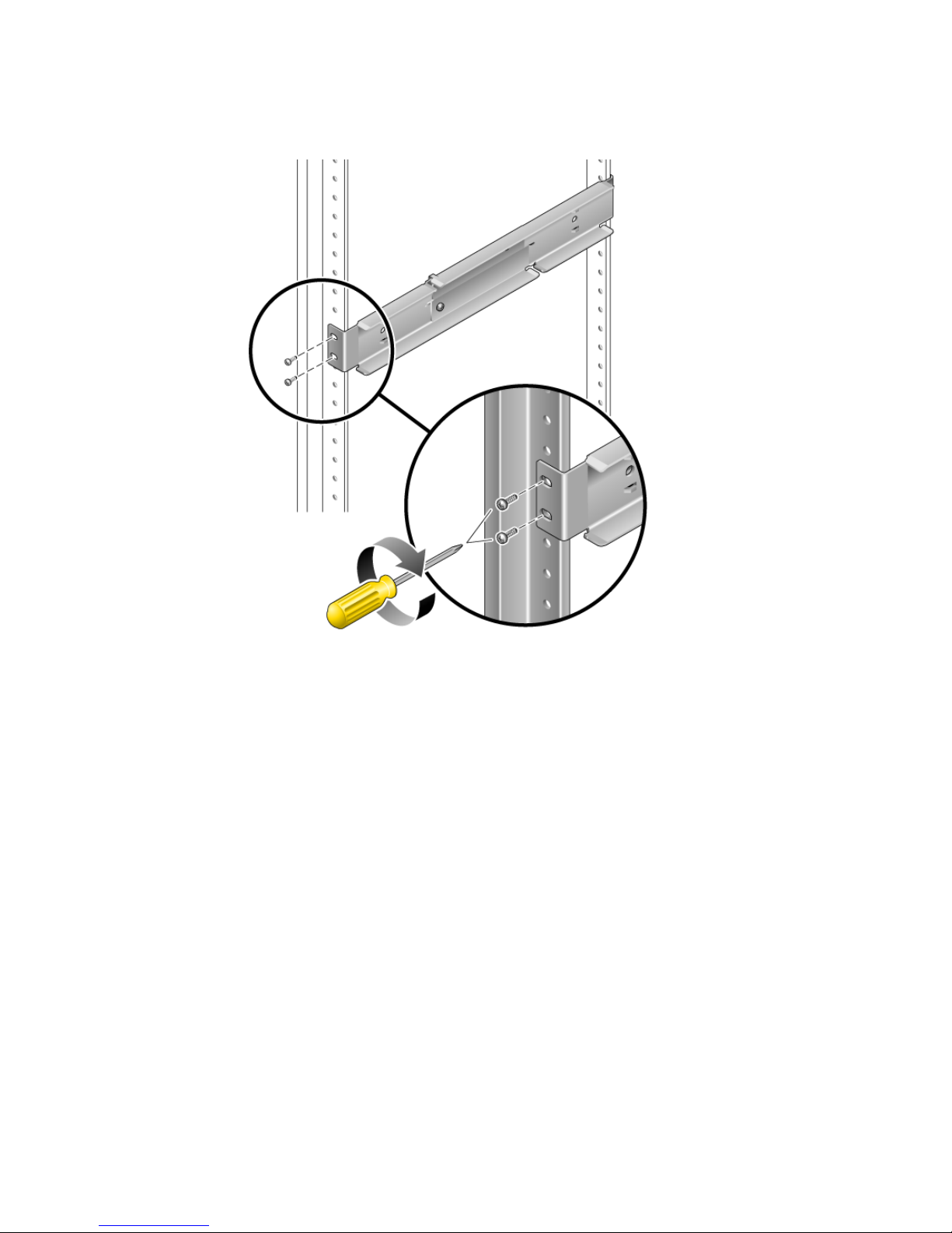
FIGURE 3-16 Securing the Front of the Adjustable Rails to the Rack
The size of the screws varies, depending on your particular rack.
4. At the rear of the rack, use two screws to secure the rear of the adjustable rails to
the rack (
FIGURE 3-17).
The size of the screws varies, depending on your particular rack.
36 Netra T2000 Server Installation Guide • September 2006
Page 53
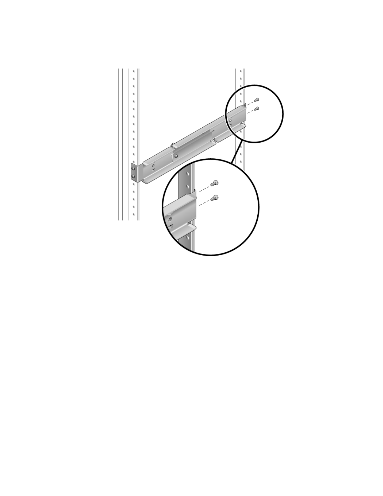
FIGURE 3-17 Securing the Rear of the Adjustable Rails to the Rack
5. Tighten the two screws at the middle of each adjustable rail (FIGURE 3-15).
6. Repeat Step 3 through Step 5 to mount the other adjustable rail into the rack.
7. Get the rear flanges from the rack kit (
8. Using one M5 × 10 SEM screw for each rear flange, loosely install the rear flange
onto the rear of each of the adjustable rails (
Do not completely secure the rear flanges to the adjustable rails, you will use these
flanges to set the rack depth for the server in a later step.
FIGURE 3-14).
FIGURE 3-18).
Chapter 3 Mounting the Server Into a 4-Post Rack 37
Page 54
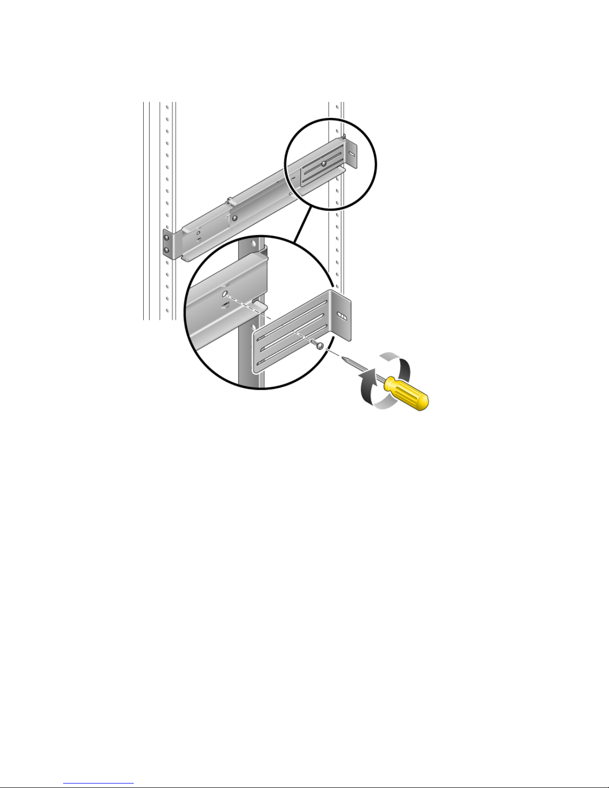
FIGURE 3-18 Installing the Rear Flange Onto the Adjustable Rail
9. Get the side rails from the rack kit (FIGURE 3-14).
10. Using eight of the M5 × 10 SEM screws (four for each side rail), secure the side
rails to the sides of the server (
FIGURE 3-19).
The side rails can accommodate rack rail setbacks (the distance from the front of the
rack to the rack rail) of 50 mm, 75 mm, or 100 mm, depending on the type of rack
you are installing the server into.
38 Netra T2000 Server Installation Guide • September 2006
Page 55
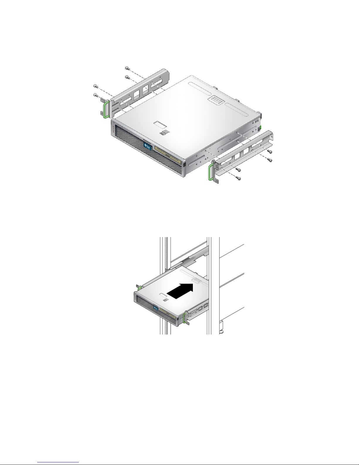
FIGURE 3-19 Securing the Side Rails to the Server
11. Lift the server into the rack and slide the server onto the adjustable rails
(
FIGURE 3-20).
FIGURE 3-20 Sliding the Server Onto the Adjustable Rails
12. Push the server to the desired depth in the rack, then go to the rear of the server
and push the rear flanges flush against the back of the server (
FIGURE 3-18).
If the rack is especially shallow, you can flip the rear flanges around so that they rest
flush against the rear of the server.
13. Lift the server out of the rack.
Chapter 3 Mounting the Server Into a 4-Post Rack 39
Page 56
14. Set the rear flanges to the desired depth in the rack, then tighten the single M5 ×
10 SEM screw on each of the flanges to secure them to the adjustable rails
(
FIGURE 3-18).
15. Lift the server into the rack and slide it onto the adjustable rails.
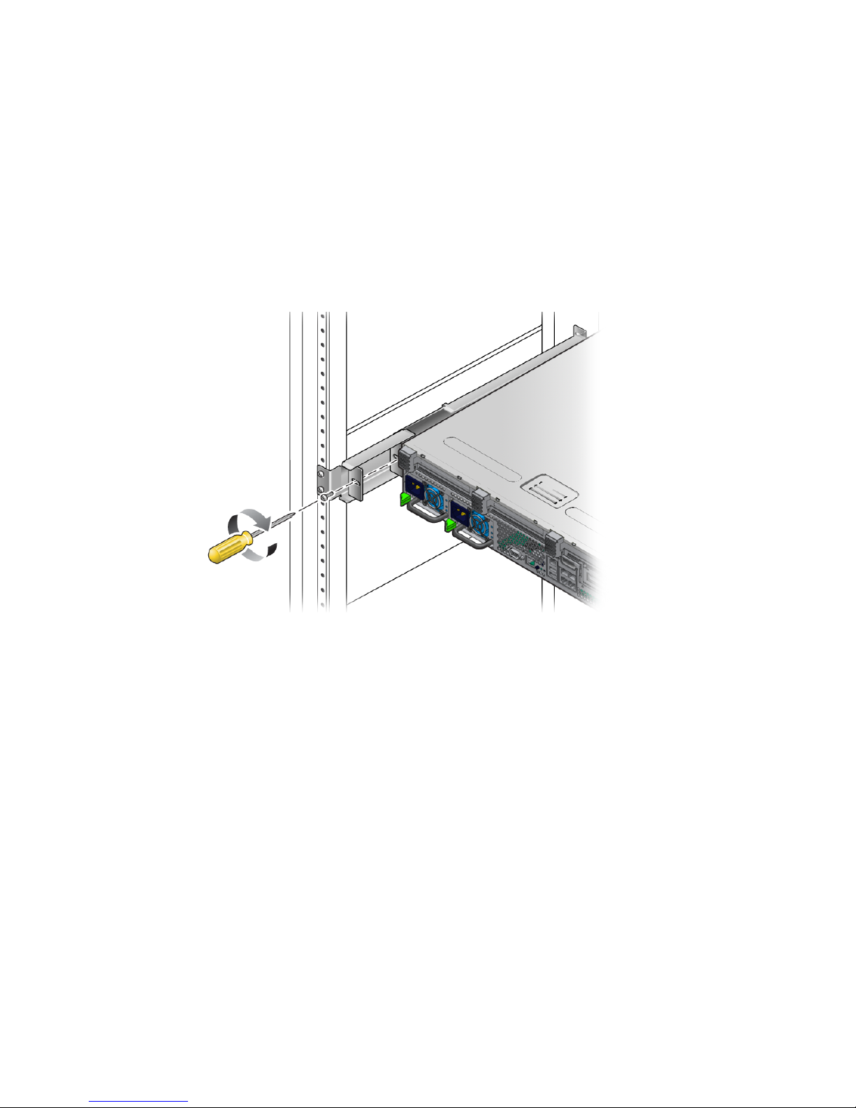
16. Push the server backward until it rests flush against the rear flanges, then use one
M5 × 10 SEM screw for each rear flange to secure the rear of the server to the rear
flanges (
FIGURE 3-21).
FIGURE 3-21 Securing the Rear of the Server to the Rear Flanges
17. At the front of the rack, use two screws per side to secure the side rails that are
attached to the server to the front of the rack (
The size of the screws varies, depending on your particular rack.
40 Netra T2000 Server Installation Guide • September 2006
FIGURE 3-22).
Page 57
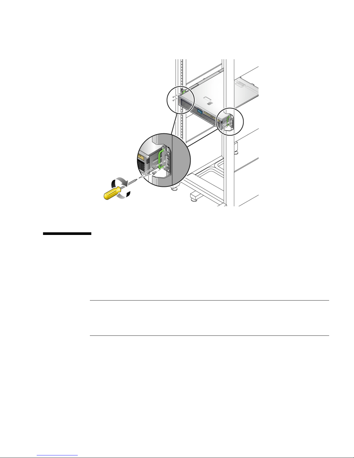
FIGURE 3-22 Securing the Front of the Server to the Front of the Rack
Installing a Server With a Hardmount in
a 19-Inch 4-Post Rack for Use With the
Cable Management Assembly
Note – Ensure that you have all of the parts in the rackmount kit before you begin
the installation of the server. See “Shipping Kit Inventory List” on page 13 and the
Netra T2000 Server Getting Started Guide, 819-5844. This document is shipped with
the server.
The rackmount kit contains two slide rail assemblies. A slide rail assembly can be
installed on either the right or left side of the rack.
A slide rail assembly consists of two parts: a slide rail and a removable mounting
bracket. The slide rail attaches to the rack posts. The mounting bracket attaches to
the chassis.
Chapter 3 Mounting the Server Into a 4-Post Rack 41
Page 58
▼ To Install the Slide Rail Assemblies
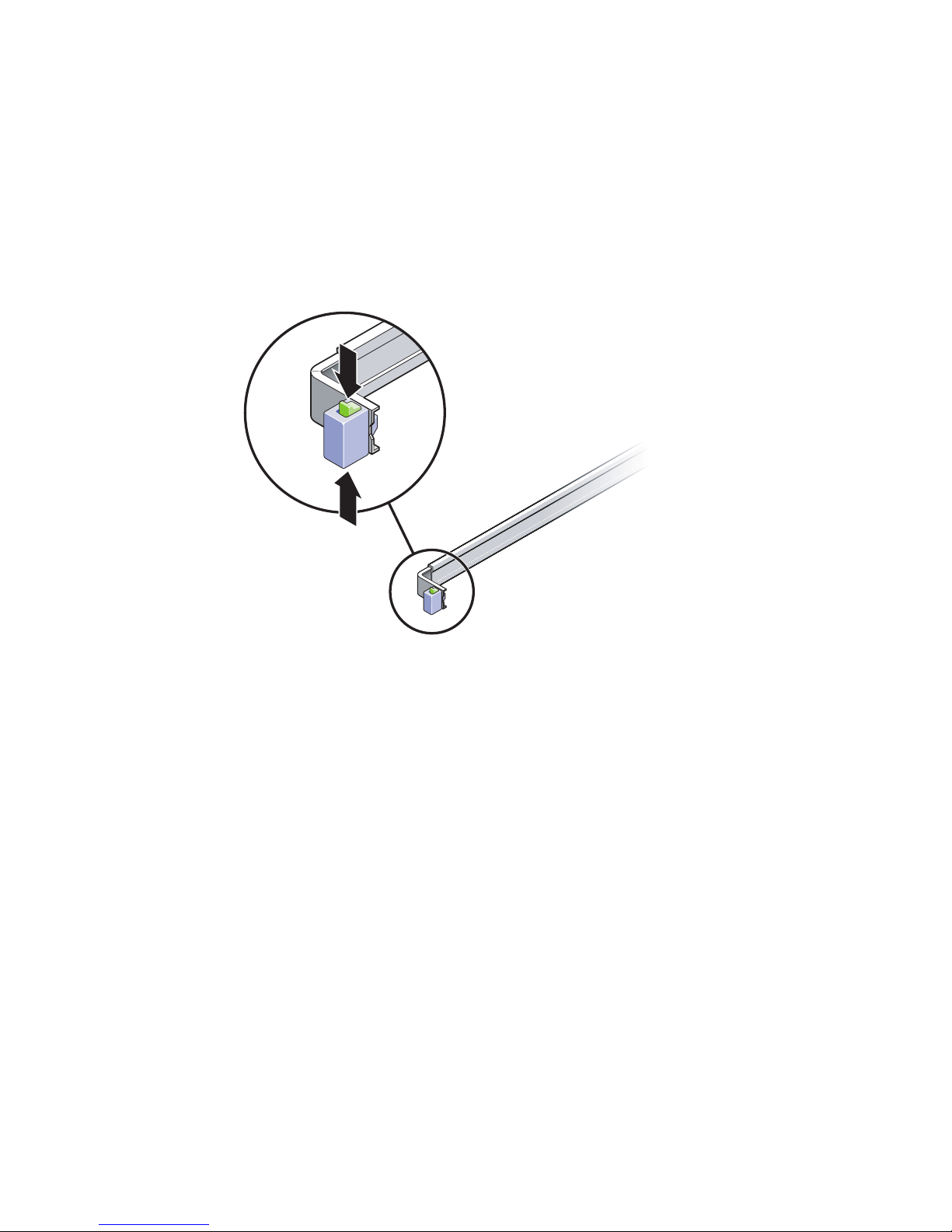
1. Pull both mounting brackets completely out of their respective slide rails:
a. Simultaneously press and hold the upper and lower lock buttons of the slide
rail lock (
FIGURE 3-23).
FIGURE 3-23 Unlocking the Slide Rail Assembly
b. Pull the mounting bracket out until it locks in the extended position.
c. Slide the mounting bracket release button in the direction shown in
FIGURE 3-24,
then slide the mounting bracket out of the slide rail.
42 Netra T2000 Server Installation Guide • September 2006
Page 59
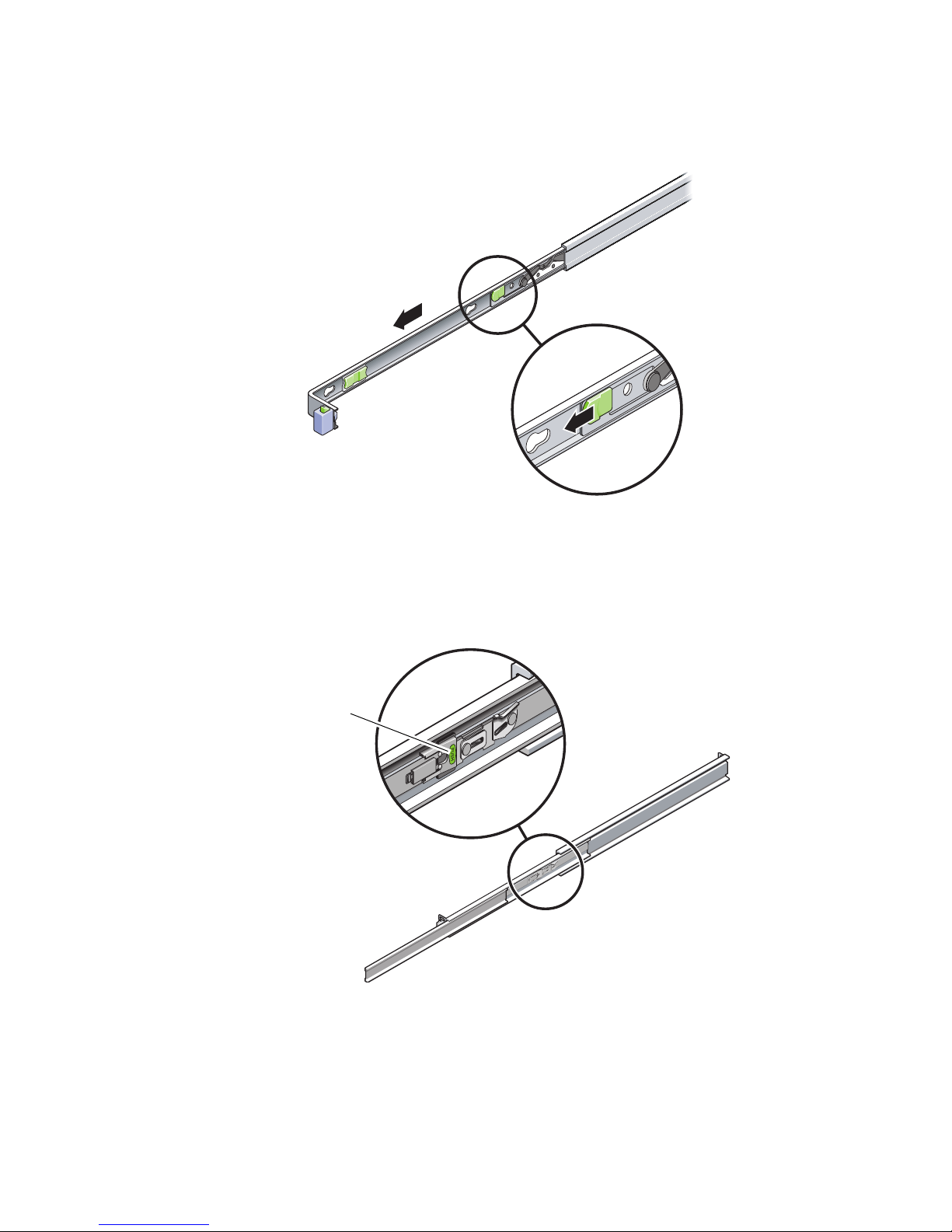
FIGURE 3-24 Location of the Mounting Bracket Release Button
d. Press the metal lever (labeled Push) on the middle section (FIGURE 3-25) of the
sliding rail, then push the middle section back into the rack.
Metal lever
FIGURE 3-25 Unlocking the Slide Rail Middle Section
2. Attach a mounting bracket to the right side of the chassis.
Chapter 3 Mounting the Server Into a 4-Post Rack 43
Page 60
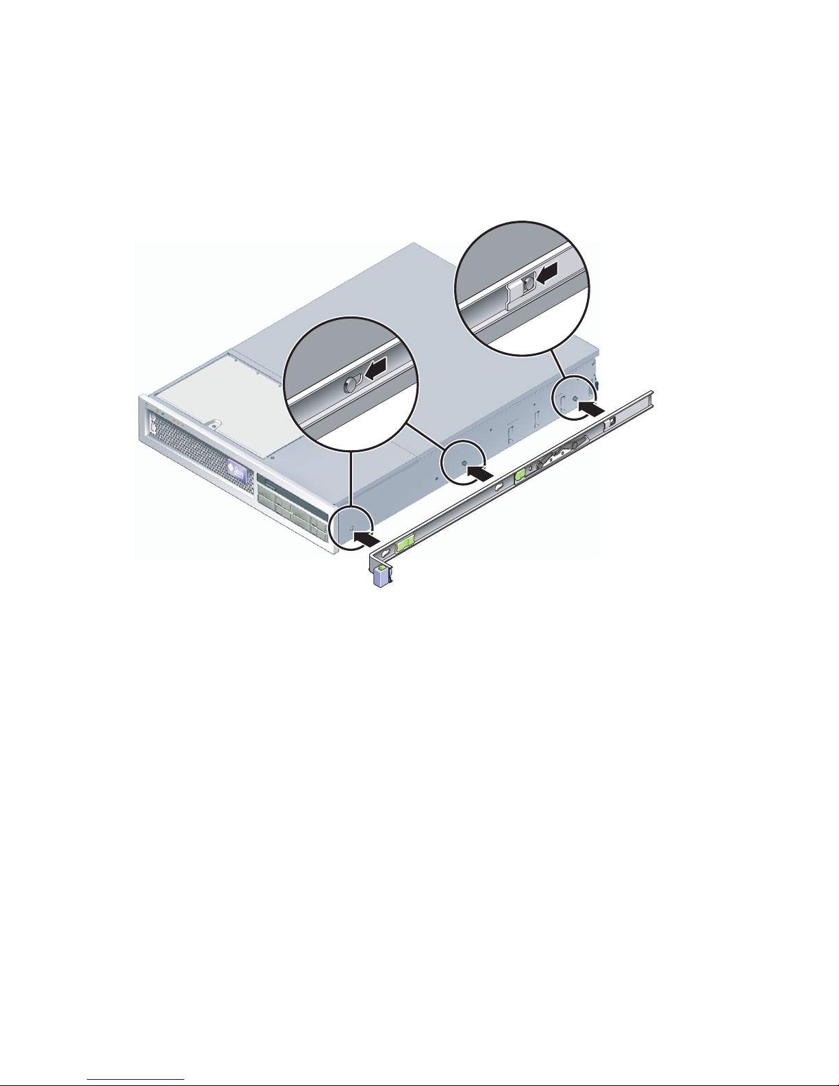
a. Position the mounting bracket against the server chassis (FIGURE 3-26) so that
the slide rail lock is at the front and the three keyed openings on the mounting
bracket are aligned with the three locating pins on the side of the chassis.
FIGURE 3-26 Attaching a Mounting Bracket to the Chassis
b. With the heads of the three locating pins protruding though the three keyed
openings in the mounting bracket, pull the mounting bracket toward the front
of the chassis until the bracket locks into place with an audible click.
c. Verify that all three locating pins are trapped in the keyed openings and that
the rear locating pin has engaged the mounting bracket lock, as shown in the
right side of
FIGURE 3-26.
3. Attach the second mounting bracket to the left side of the chassis.
4. Determine which rack hole numbers to use when attaching the slide rails to the
rack posts.
The server is two rack units tall (2 RU). The slide rails occupy the lower half of the 2
RU space.
5. Determine which screws you will use to mount the slide rails.
44 Netra T2000 Server Installation Guide • September 2006
Page 61
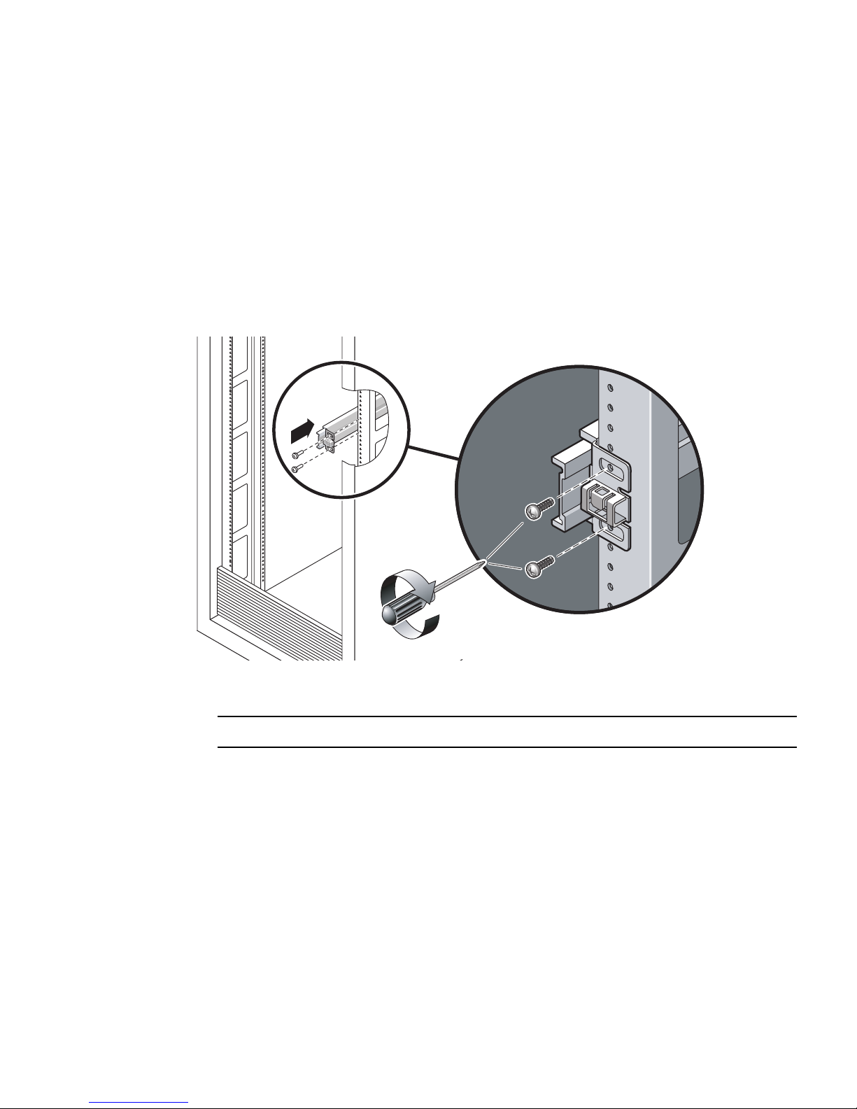
■ If your rack has threaded mounting holes in the rack posts, determine whether
the threads are metric or standard. Select the appropriate screws from the package
included in the mounting kit.
■ If your rack does not have threaded mounting holes, the mounting screws are
secured with a caged nut.
6. Attach a slide rail to the right front rack post.
a. Loosely attach the front of a slide rail to the right front rack post (
using two screws.
FIGURE 3-27 Mounting a Slide Rail
FIGURE 3-27)
Note – Do not tighten the screws yet.
b. Adjust the length of the slide rail by sliding the rear mounting flange to reach
the outside edge of the rear rack post.
c. Loosely attach the rear of the slide rail to the rear rack post with two screws.
7. Attach the second slide rail to the left rack posts in a similar manner.
Do not tighten the screws.
8. Use the slide rail spacing tool to adjust the distance between the slide rails:
a. At the front of the rack, plug the left side of the tool into slots at the end of the
left rail (
FIGURE 3-28).
Chapter 3 Mounting the Server Into a 4-Post Rack 45
Page 62
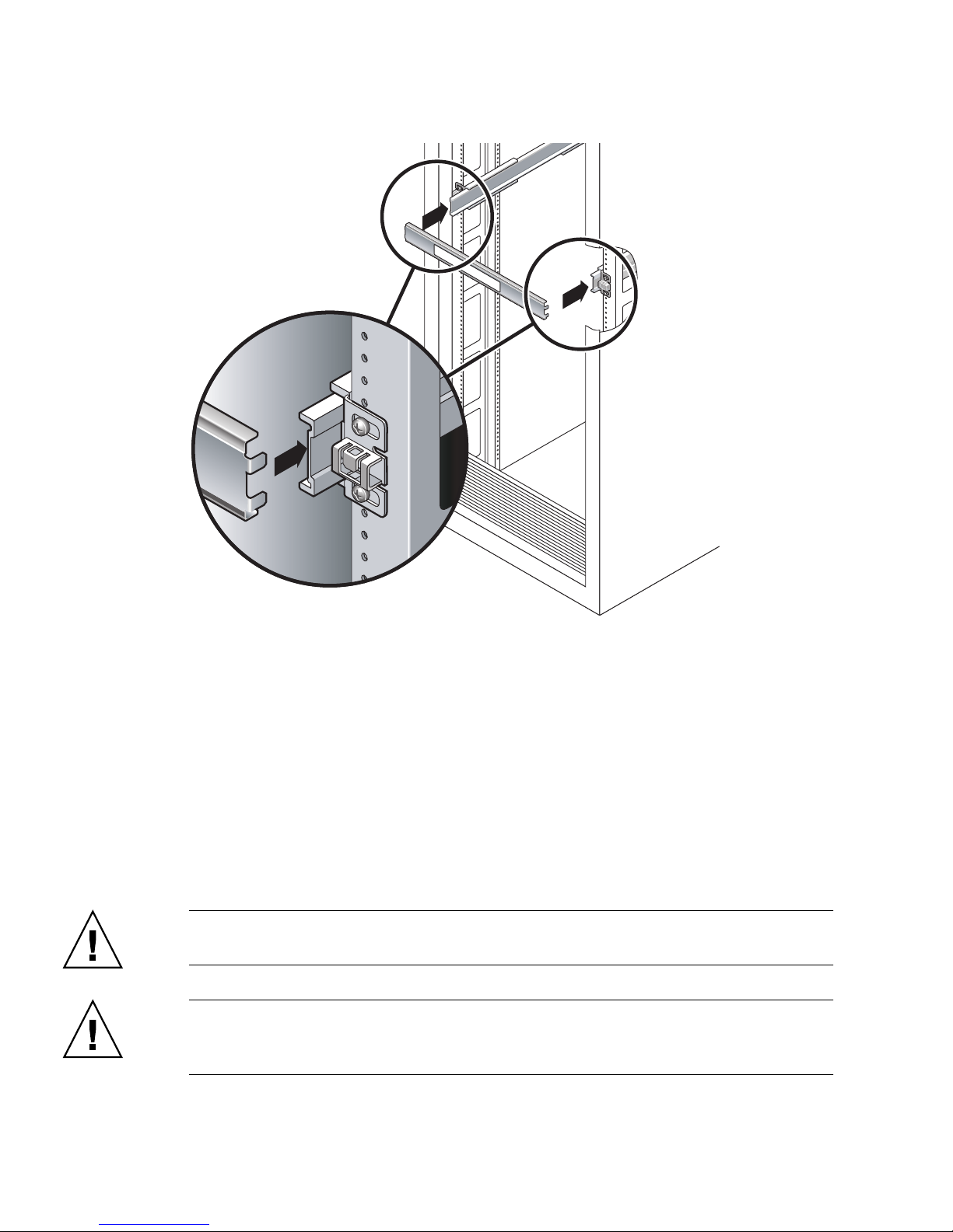
FIGURE 3-28 Adjusting the Distance Between the Slide Rails
b. Insert the right side of the tool into the front end of the right rail, while sliding
the end of the rail to the right or left as needed to enable the ends of the tool to
enter the ends of both rails.
The distance between the rails is now equal to the width of the server with
mounting brackets.
c. Tighten the screws to lock the ends of the rails in place.
d. At the rear of the rack, repeat Step a through Step c for the rear ends of the rails.
9. Deploy the antitilt bar, if the chassis or rack is so equipped.
Caution – The weight of the server on extended slide rails can be enough to
overturn a cabinet.
Caution – The server weighs approximately 40 lb (18 kg). Two people are required
to lift and mount the server into a rack enclosure when using the procedures in this
chapter.
46 Netra T2000 Server Installation Guide • September 2006
Page 63
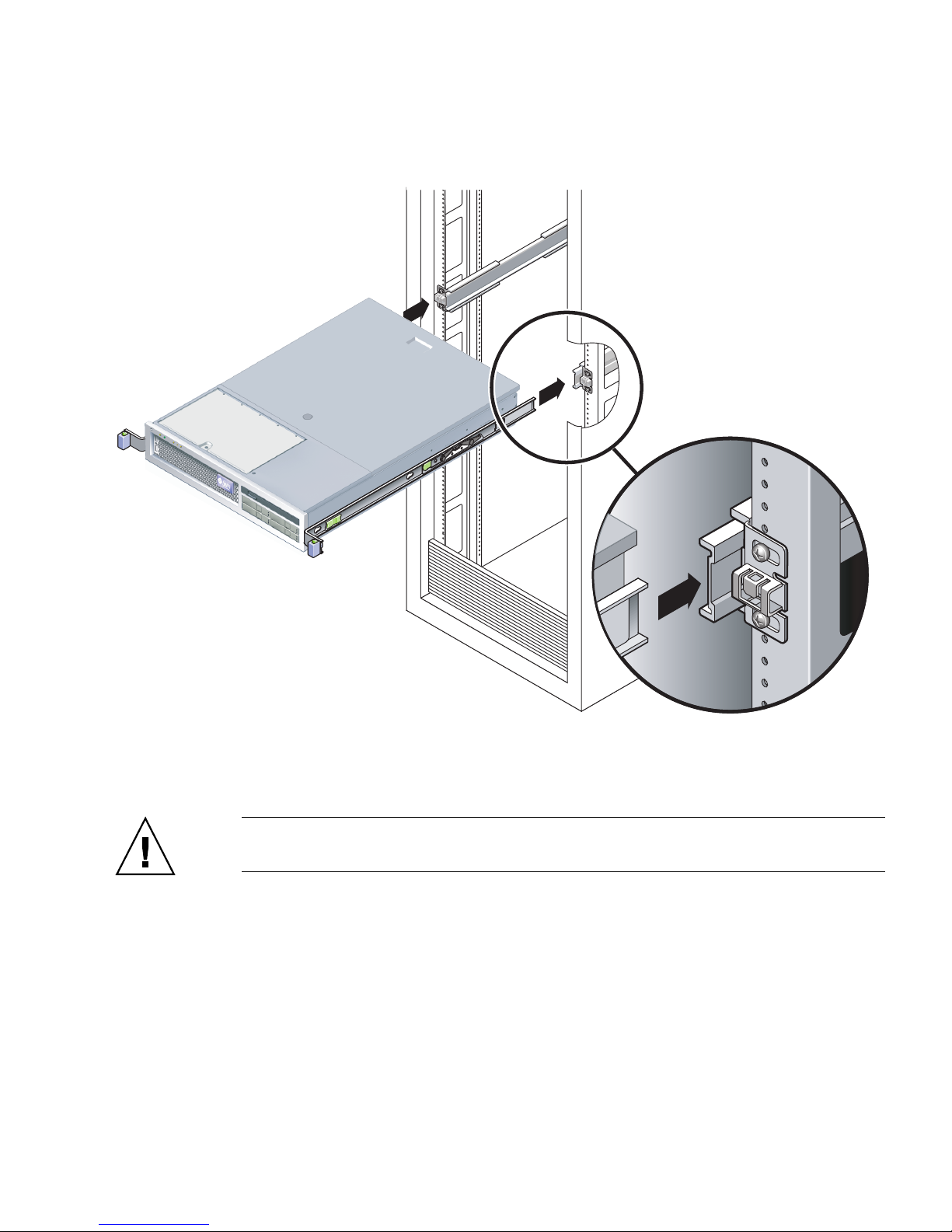
10. Insert the ends of the mounting brackets into the sliding rails (FIGURE 3-29).
FIGURE 3-29 Mounting the Chassis on the Slide Rails
11. Slide the chassis into the rack.
Caution – Verify that the server is securely mounted in the rack, and that the slide
rails are locked to the mounting brackets, before continuing.
▼ To Install the Cable Management Assembly
The cable management assembly (CMA) clips into the ends of the left and right
sliding rail assemblies. No screws are necessary for mounting the CMA.
Chapter 3 Mounting the Server Into a 4-Post Rack 47
Page 64
The right sides of the two CMA arms have hinged extensions. On the
manufacturer’s instruction sheet, the smaller extension is called the inner CMA
connector. It attaches to the right mounting bracket. The larger extension is called
the CMA outer connector, and attaches to the right sliding rail.
Caution – Support the CMA during this installation. Do not permit the assembly to
hang by its own weight until it is secured by all three attachment points.
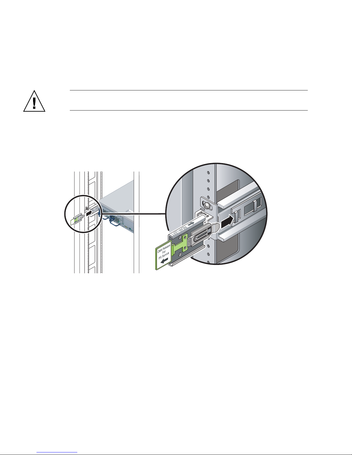
1. At the rear of the rack, plug the CMA rail extension into the end of the left sliding
rail assembly (
FIGURE 3-30).
The tab at the front of the rail extension will click into place.
FIGURE 3-30 Inserting the CMA Rail Extension Into the Rear of the Left Slide Rail
2. Insert the smaller CMA extension into the clip located at the end of the mounting
bracket (
48 Netra T2000 Server Installation Guide • September 2006
FIGURE 3-31).
Page 65
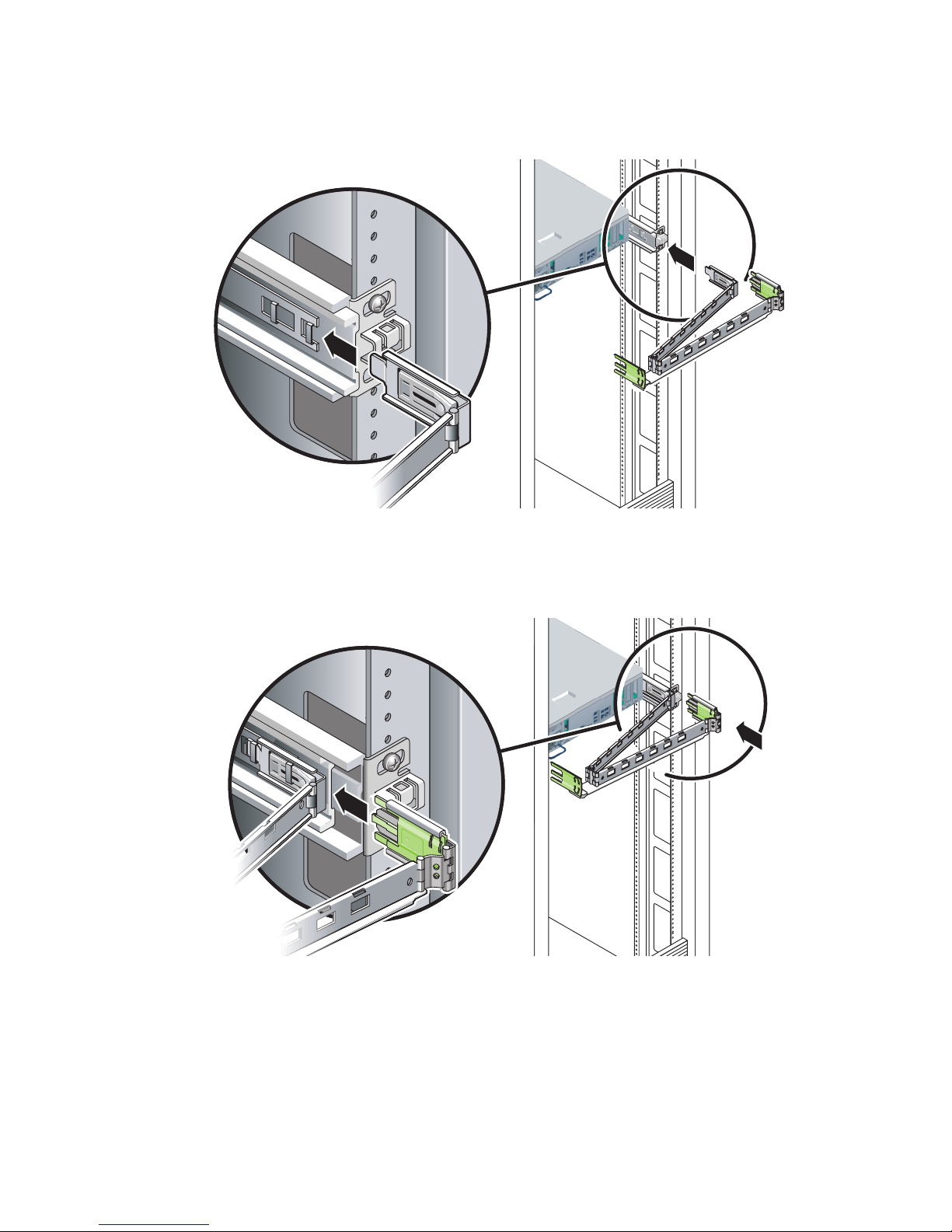
FIGURE 3-31 Mounting the Inner CMA Connector
3. Insert the larger extension into the end of the right rail (FIGURE 3-32).
FIGURE 3-32 Attaching the Outer CMA Connector
Chapter 3 Mounting the Server Into a 4-Post Rack 49
Page 66
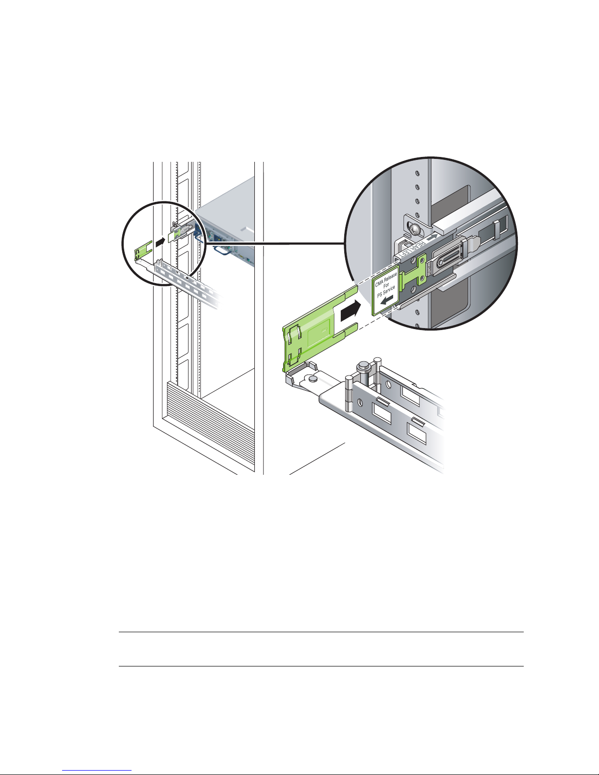
4. Insert the hinged plastic connector at the left side of the CMA fully into the CMA
rail extension (
The plastic tab on the CMA rail extension locks the hinged plastic connector in
place.
FIGURE 3-33).
FIGURE 3-33 Mounting the Left Side of the Rail
▼ To Verify the Operation of the Slide Rails and
the CMA
If you are using the CMA on a rack kit with slide rails, follow these steps to ensure
that the CMA will not interfere with the ability to move the rack. You must first
connect cables to the server.
Tip – Two people are needed for this procedure, one to move the server in and out
of the rack, and one to observe the cables and CMA.
50 Netra T2000 Server Installation Guide • September 2006
Page 67
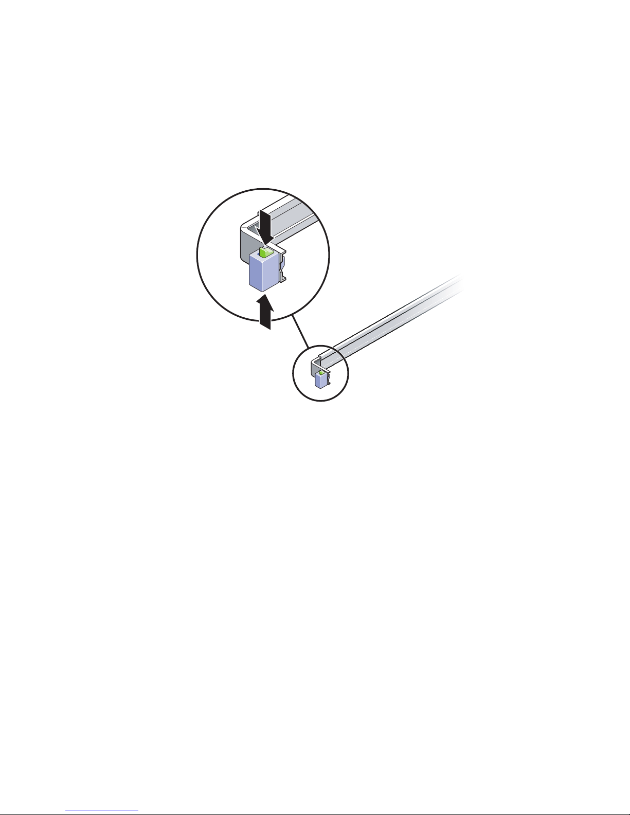
1. For a cabinet or a free-standing rack, deploy the antitilt bar.
2. Unlock the slide lock buttons (
FIGURE 3-34) at the right and lefts sides of the server
chassis, and slowly pull the server out of the rack until the slide rails reach their
stops.
FIGURE 3-34 Unlocking the Slide Rail Assembly
3. Inspect the attached cables for any binding or kinks.
4. Verify that the CMA extends fully and does not bind in the slide rails.
5. When the server is fully extended out, release the slide rail lever stops
(
FIGURE 3-35).
6. Push both levers simultaneously and slide the server back into the rack.
Chapter 3 Mounting the Server Into a 4-Post Rack 51
Page 68
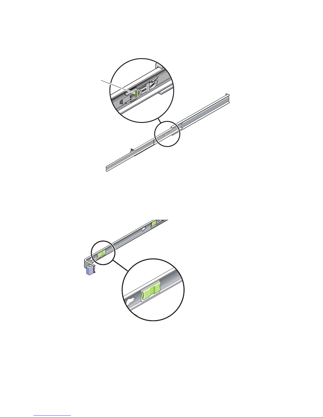
Metal lever
FIGURE 3-35 Unlocking the Slide Rail Lever Stops
7. Simultaneously unlock both slide rail release buttons (FIGURE 3-36) and push the
server completely into the rack.
FIGURE 3-36 Slide Rail Release Button
The server should stop after approximately 15 in. (40 cm) of travel.
8. Verify that the cables and the CMA retracted without binding.
52 Netra T2000 Server Installation Guide • September 2006
Page 69

9. Adjust the cable hangers and CMA as required.
Chapter 3 Mounting the Server Into a 4-Post Rack 53
Page 70

54 Netra T2000 Server Installation Guide • September 2006
Page 71
CHAPTER
4
Mounting the Server Into a 2-Post
Rack
This chapter provides instructions for installing the server in an open 2-post rack.
This chapter contains the following sections:
■ “2-Post Rackmounting Options” on page 56
■ “Hardmounting the Server in a 23-Inch 2-Post Rack” on page 56
■ “Hardmounting the Server in a 19-Inch 2-Post Rack” on page 61
Note – References to left and right are from your viewpoint as you face either the
front or rear of the equipment.
Caution – The server is heavy. Two people are required to lift and mount the server
into a rack enclosure when following the procedures in this chapter.
55
Page 72

2-Post Rackmounting Options
The server ships with a 19-inch, 4-post hardmount rack kit (see “Hardmounting the
Server in a 19-Inch 4-Post Rack” on page 22 for installation instructions).
lists two additional 2-post rackmount kit options that can be ordered from Sun. This
chapter provides installation instructions for these rackmount kit options.
TABLE 4-1 Optional Rackmount Kits
Mounting Kit Installation Instructions
23-inch 2-post rackmount kit “To Install a Server With a Hardmount in a 23-Inch
2-Post Rack” on page 56
19-inch 2-post rackmount kit “To Install a Server With a Hardmount in a 19-Inch
2-Post Rack” on page 61
Note – If you have more than six DC-powered servers in the same rack, you might
exceed Telcordia NEBS EMI limits.
TABLE 4-1
Hardmounting the Server in a 23-Inch 2Post Rack
▼ To Install a Server With a Hardmount in a 23-
Inch 2-Post Rack
The hardmount kit for a 23-inch 2-post rack consists of:
■ Two side brackets
■ Two rail guides
■ Two rear plates
■ Bag of screws
Note – The 23-inch 2-post rackmount kit supports rack web thicknesses (the width
of the rack post) of 76.20 mm (3 in.), 101.6 mm (4 in.), and 127 mm (5 in.).
56 Netra T2000 Server Installation Guide • September 2006
Page 73
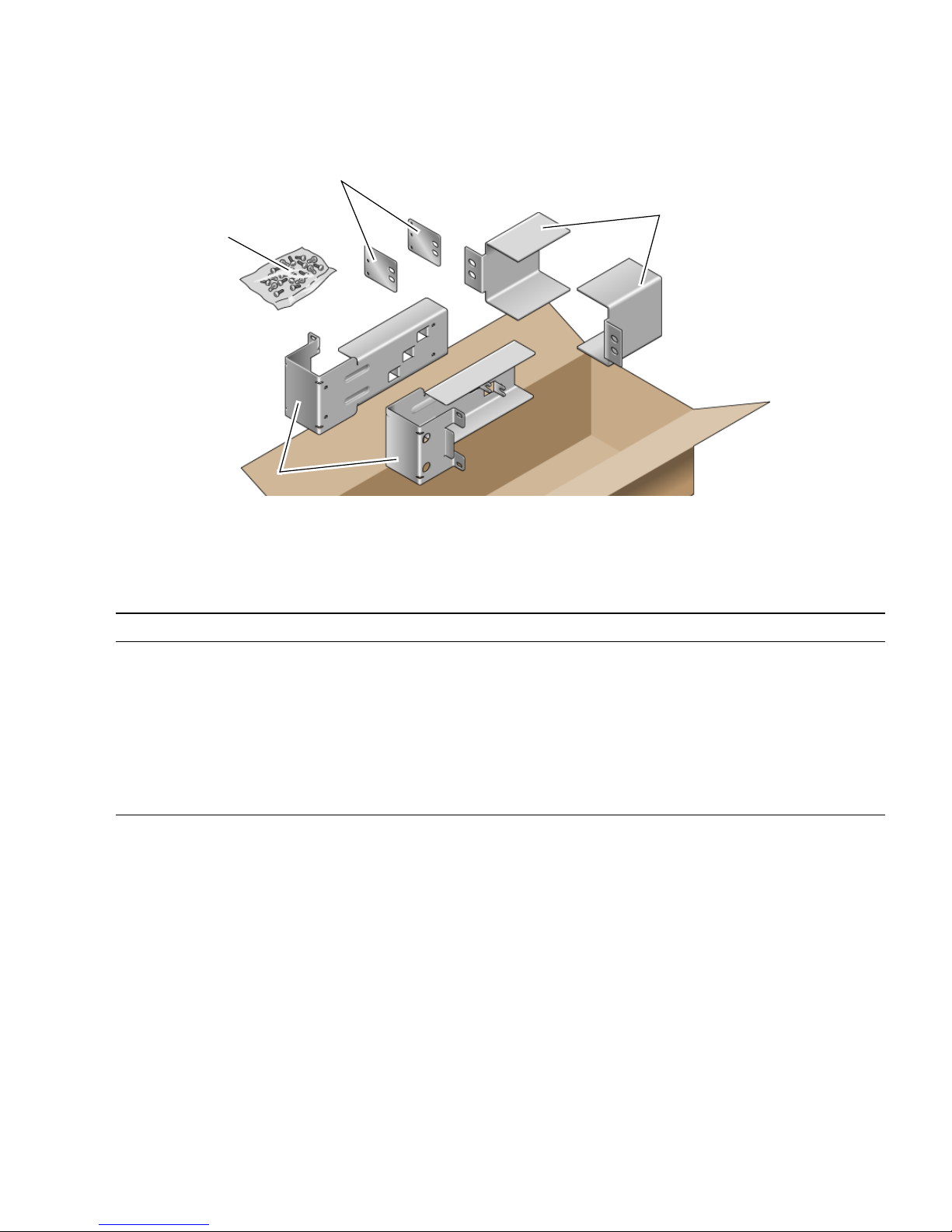
Rear plates
Screws
Side brackets
FIGURE 4-1 Contents of the Hardmount 23-Inch 2-Post Kit
TABLE 4-2 Hardmount 23-Inch 2-Post Rackmount Screw Kit Contents
Number Description Where Used
Rail guides
10 M5 x 10 SEM screws 8 for side brackets, 2 for rear plates
10 M5 x 12.7 mm screws 10 for rack, if appropriate
10 M6 x 13 mm screws 10 for rack, if appropriate
9 M6 square clip nuts 9 for rack, if appropriate
12 10-32 x 0.5 in. combo head screws 12 for rack, if appropriate
12 12-24 x 0.5 in. combo head screws 12 for rack, if appropriate
1. Get the side brackets from the rack kit (FIGURE 4-1).
2. Using eight of the M5 × 10 SEM screws (four for each side bracket), secure the
side brackets to the sides of the server (
FIGURE 4-2).
Chapter 4 Mounting the Server Into a 2-Post Rack 57
Page 74
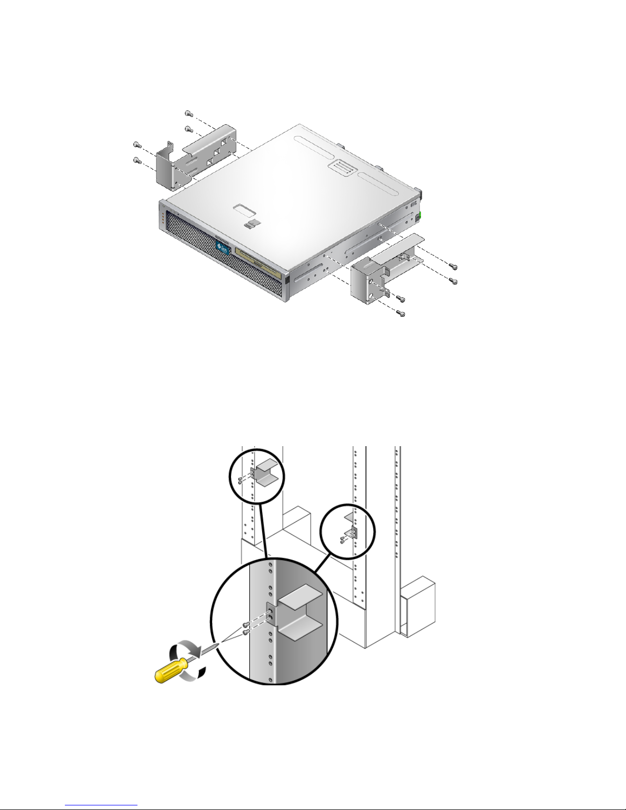
FIGURE 4-2 Securing the Side Brackets to the Side of the Server
3. Get the rail guides from the rack kit (FIGURE 4-1).
4. Lift the rail guides to the desired height in the rack and, using two screws each,
secure both rail guides to the rack (
FIGURE 4-3).
The size of the screws varies, depending on your particular rack.
FIGURE 4-3 Installing the Rail Guides in the Rack
58 Netra T2000 Server Installation Guide • September 2006
Page 75
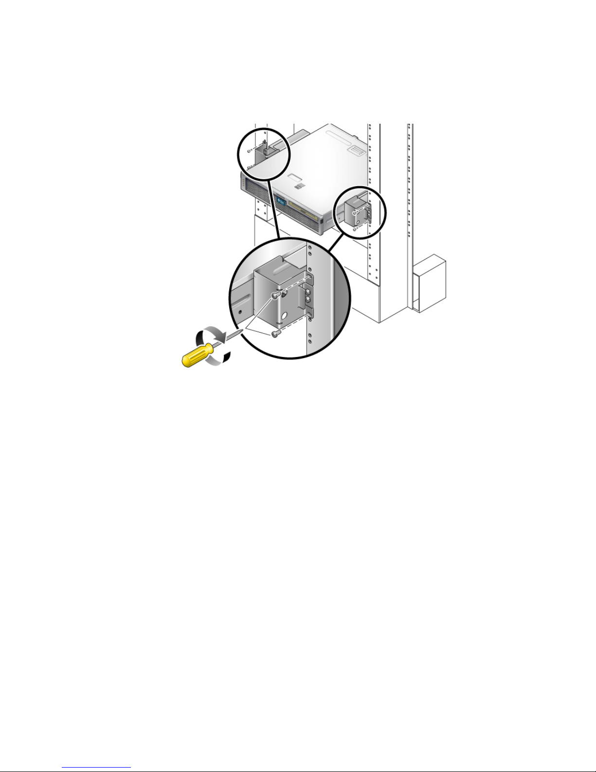
5. Lift the server into the rack and slide the server onto the rail guides (FIGURE 4-4).
FIGURE 4-4 Installing and Securing the Server in the 2-Post Rack
6. Using two screws on each side, secure each side bracket on the server to the front
of the rack (
FIGURE 4-4).
The size of the screws varies, depending on your particular rack.
7. (Optional) If your environment contains especially high vibrations, use the rear
plates to further secure the server to the rack (
FIGURE 4-1).
The rear plates attach to the rear of the post and to one of the three eyelets on each
side bracket, depending on the thickness of the post.
a. Using one M5 × 10 SEM screw for each rear plate, loosely install the screw in
one of the three positions on the rear plate (
FIGURE 4-5).
The position varies depending on the thickness of the rail in the rack. For
example,
FIGURE 4-5 shows where you would install the screw for the middle rack
position on the rear plate.
Chapter 4 Mounting the Server Into a 2-Post Rack 59
Page 76
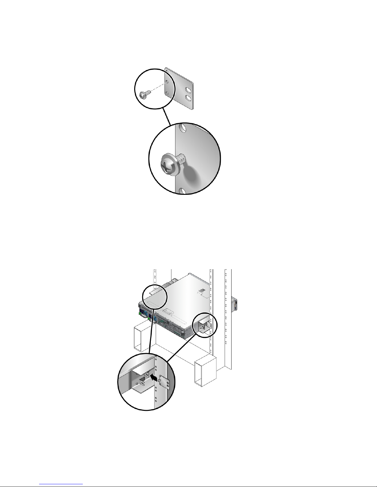
FIGURE 4-5 Installing a Screw on the Middle Rack Position on the Rear Plate
b. Slide the rear plate in so that the screw slides into position into one of the
eyelets.
The screw head should be facing the rear of the server and the other side of the
rear plate should be in front of the rack post (
FIGURE 4-6).
FIGURE 4-6 Installing the Rear Plate to the Side Bracket
60 Netra T2000 Server Installation Guide • September 2006
Page 77
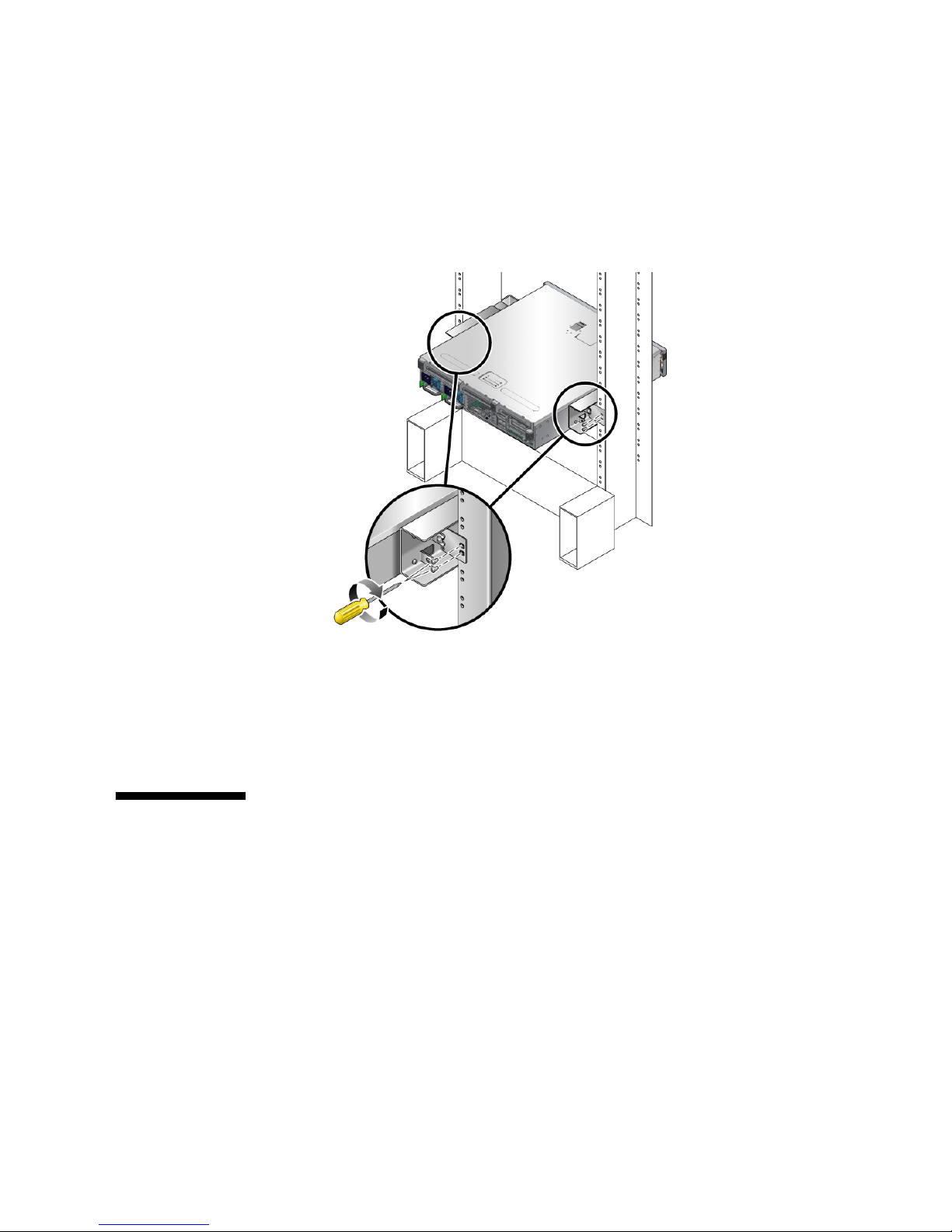
c. Tighten the screw to secure the rear plate to the eyelet on the side bracket
(
FIGURE 4-6).
d. Using two screws, secure the other side of the rear plate to the back of the post
(
FIGURE 4-7).
FIGURE 4-7 Securing the Rear Plate to the Back of the Post
The size of the screws varies, depending on your rack.
e. Repeat Step a through Step d to secure the rear plate on the other post.
Hardmounting the Server in a 19-Inch 2Post Rack
▼ To Install a Server With a Hardmount in a 19-
Inch 2-Post Rack
The hardmount kit for a 19-inch 2-post rack consists of:
■ Two side brackets
Chapter 4 Mounting the Server Into a 2-Post Rack 61
Page 78
■ Two rear plates
■ Bag of screws
Note – The 19-inch 2-post rackmount kit supports rack web thicknesses (the width
of the rack post) of 76.20 mm (3 in.), 101.6 mm (4 in.), and 127 mm (5 in.).
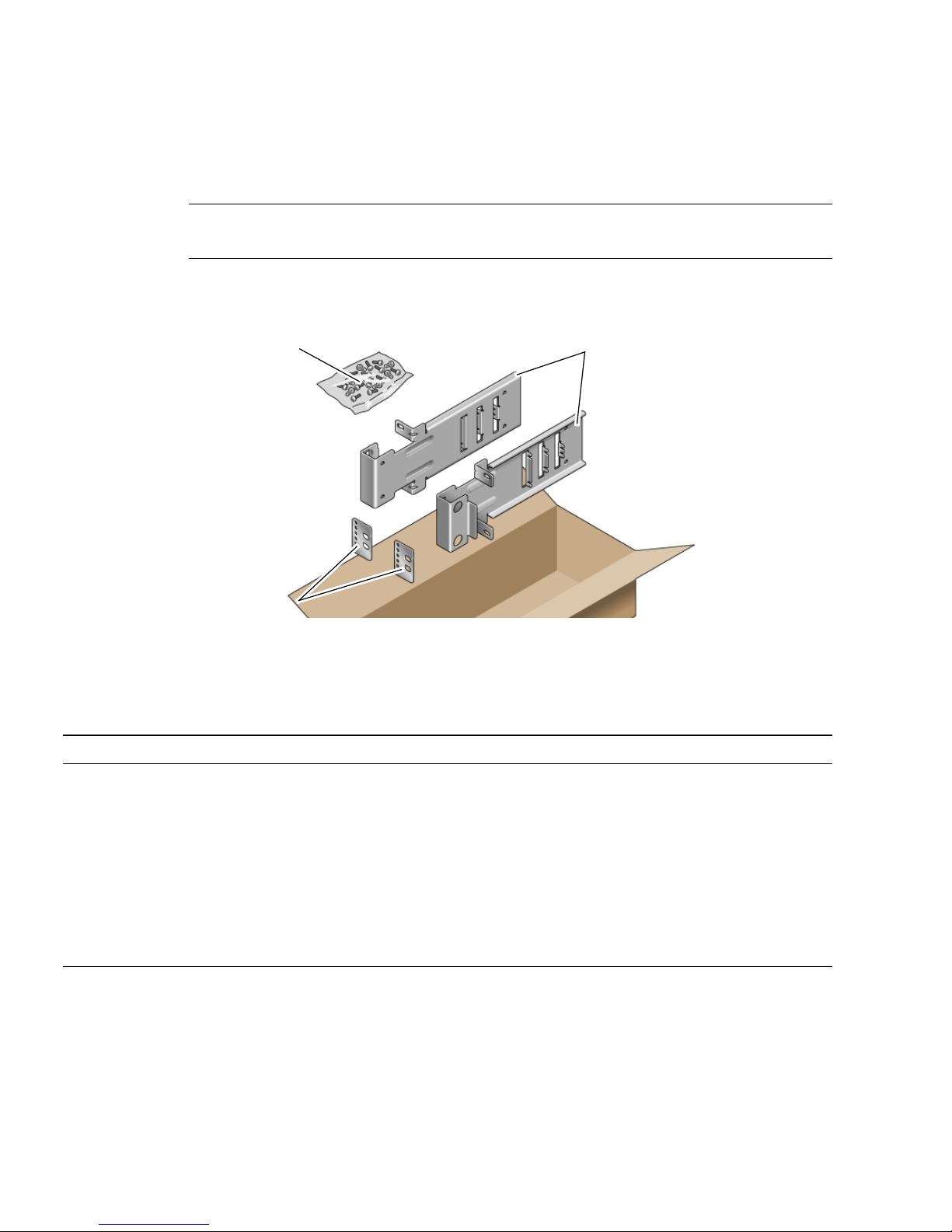
Screws
Side brackets
Rear plates
FIGURE 4-8 Contents of the Hardmount 19-Inch 2-Post Kit
TABLE 4-3 Hardmount 19-Inch 2-Post Rackmount Screw Kit Contents
Number Description Where Used
10 M5 x 10 SEM screws 8 for side brackets, 2 extra
6 M3 x 8 SEM screws 4 for rear plates, 2 extra
10 M5 x 12.7 mm screws 10 for rack, if appropriate
10 M6 x 13 mm screws 10 for rack, if appropriate
9 M6 square clip nuts 9 for rack, if appropriate
12 10-32 x 0.5 in. combo head screws 12 for rack, if appropriate
12 12-24 x 0.5 in. combo head screws 12 for rack, if appropriate
1. Get the side brackets from the rack kit (FIGURE 4-8).
2. Using four of the M5 × 10 SEM screws for each side bracket, secure the side
brackets to the sides of the server (
62 Netra T2000 Server Installation Guide • September 2006
FIGURE 4-9).
Page 79
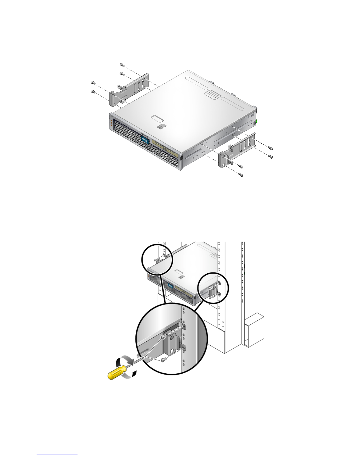
FIGURE 4-9 Securing the Side Brackets to the Side of the Server
3. Lift the server into the rack.
4. Using two screws for each bracket, secure the front of the server to the front of the
rack (
FIGURE 4-10).
FIGURE 4-10 Installing and Securing the Server in the 2-Post Rack
Chapter 4 Mounting the Server Into a 2-Post Rack 63
Page 80
The size of the screws varies, depending on your rack.
5. (Optional) If your environment contains especially high vibrations, use the rear
plates to further secure the server to the rack (
FIGURE 4-8).
The rear plates attach to the rear of the post and to one of the three sets of eyelets on
each side bracket, depending on the thickness of the post.
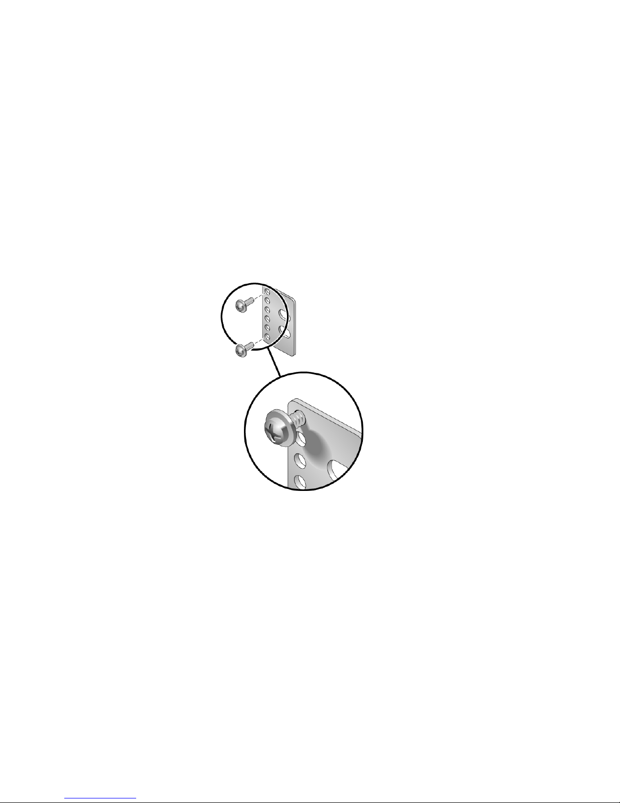
a. Using two of the M3 × 8 SEM screws for each rear plate, loosely install the
screws in one of the six positions on the rear plate (
FIGURE 4-11).
The position varies depending on the thickness of the rail in the rack. For
example,
FIGURE 4-11 shows where you would install the screws for the optimum
rack position on the rear plate.
FIGURE 4-11 Installing Screws on the Optimum Rack Position on the Rear Plate
b. Slide the rear plate in so that the screws slide into position into one set of the
eyelets.
The screw heads should be facing the rear of the server and the other side of the
rear plate should be in front of the rack post (
64 Netra T2000 Server Installation Guide • September 2006
FIGURE 4-12).
Page 81
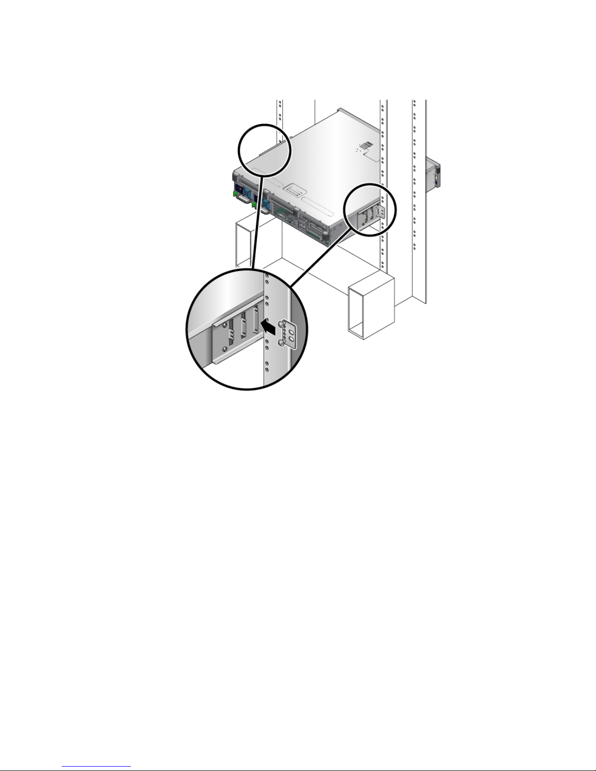
FIGURE 4-12 Installing the Rear Plate to the Side Bracket
c. Tighten the screws to secure the rear plate to the set of eyelets on the side
bracket (
FIGURE 4-12).
d. Using two screws, secure the other side of the rear plate to the back of the post
(
FIGURE 4-13).
Chapter 4 Mounting the Server Into a 2-Post Rack 65
Page 82
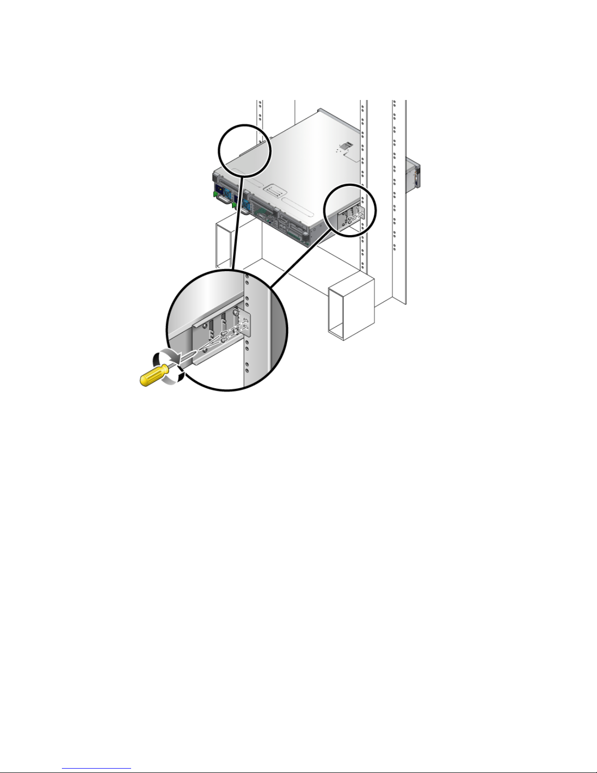
FIGURE 4-13 Securing the Rear Plate to the Rack
The size of the screws varies, depending on your rack.
e. Repeat Step a through Step d to secure the rear plate on the other post.
66 Netra T2000 Server Installation Guide • September 2006
Page 83

CHAPTER
5
Cabling the Server
This chapter provides instructions for cabling the server. Topics include:
■ “Data Ports and Cabling Notes” on page 67
■ “Connecting Cables” on page 69
■ “Managing Cables With the CMA” on page 75
Note – References to left and right are from your viewpoint as you face either the
front or rear of the equipment.
Data Ports and Cabling Notes
Port Locations
See FIGURE 5-1 for the locations of the ports on the server.
67
Page 84
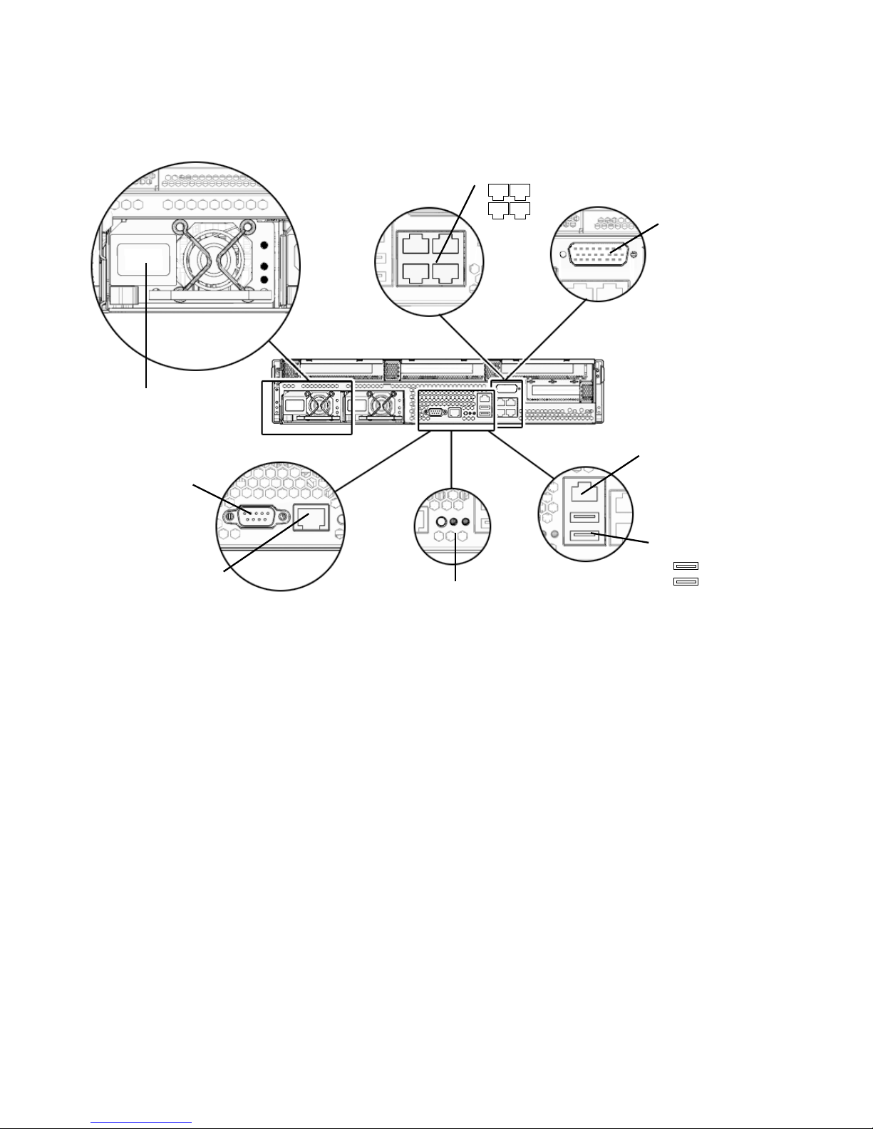
Power connection
TTYA serial
port
SC serial mgt
port
GBE ports
Indicators
2
0 1
3
Alarm
port
SC NET MGT
port
USB ports
1
0
FIGURE 5-1 Rear Panel Features
Cabling Notes
The following list describes the server’s cable connections and ports:
■ Minimum cable connections for the server:
■ At least one server on-board Ethernet network connection (GBE ports)
■ The system controller serial management port (SERIAL MGT port) or, the
system controller network management port (NET MGT port)
■ Power cables for the two power supplies
■ System controller (SC) management ports: There are two SC management ports
for use with the ALOM system controller.
■ The SC serial management port (labeled SERIAL MGT) uses an RJ-45 cable and
is always available. This is the default connection to the ALOM system
controller.
68 Netra T2000 Server Installation Guide • September 2006
Page 85
■ The SC network management port (labeled NET MGT) is the optional
connection to the ALOM system controller. This port is not available until you
have configured network settings for the system controller (through the SC
serial management port). See “Enabling the System Controller Network
Management Port” on page 80. The SC network management port uses an
RJ-45 cable for a 10/100BASE-T connection. This port does not support
connections to Gigabit networks.
■ Ethernet ports : Labeled NET0, NET1, NET2, and NET3. The Ethernet interfaces
operate at 10 Mbyte/sec, 100 Mbyte/sec, and 1000 Mbyte/sec.
■ TTYA serial port: Use the DB-9 connector with a null modem cable for serial
devices. This port appears as ttya in Solaris OS and OpenBoot messages. This
port is not connected to the SC serial management port.
■ USB Ports: USB ports support hot-plugging. You can connect and disconnect USB
cables and peripheral devices while the server is running, without affecting
system operations.
■ You can only perform USB hot-plug operations while the OS is running. USB
hot-plug operations are not supported when the OpenBoot PROM ok prompt
is displayed or before the system has completed booting.
■ You can connect up to 126 devices to each of the two USB controllers, for a
total of 252 USB devices per server.
■ Input power cables: Do not attach power cables to the power supplies until you
have finished connecting the data cables, and have connected the server to a serial
terminal or a terminal emulator (PC or workstation). The server goes into Standby
mode and the ALOM system controller initializes as soon as the input power
cables are connected to the power source. System messages might be lost if the
server is not connected to a terminal, PC, or workstation at this time.
Connecting Cables
▼ To Connect the Ethernet Network Cables
The server has four RJ-45 Gigabit Ethernet network connectors. They are marked
NET0, NET1, NET2, and NET3 (
FIGURE 5-2).
Chapter 5 Cabling the Server 69
Page 86
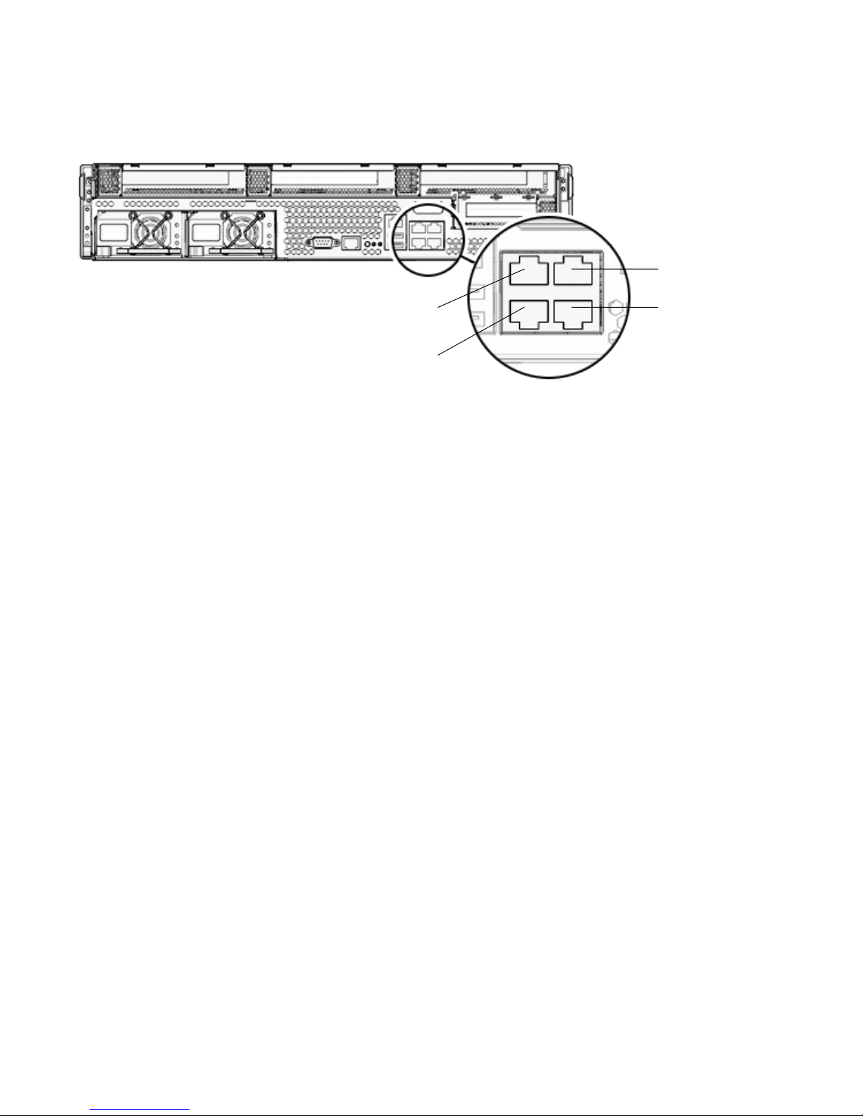
NET3
NET2
NET0
FIGURE 5-2 Ethernet Network Connections
NET1
1. Connect a Category 5 cable from your network switch or hub to Ethernet Port 0
(NET0) on the rear of the chassis.
2. As needed, connect Category 5 cables from your network switch or hub to the
remaining Ethernet ports (NET1, NET2, NET3).
▼ To Connect the SC Serial Management Port
Use this port for server management. This port is needed to set up the SC network
management port, as detailed in “Enabling the System Controller Network
Management Port” on page 80.
The SC serial management port is marked SER MGT. It is the leftmost RJ-45 port on
the rear of the chassis (
FIGURE 5-3).
70 Netra T2000 Server Installation Guide • September 2006
Page 87
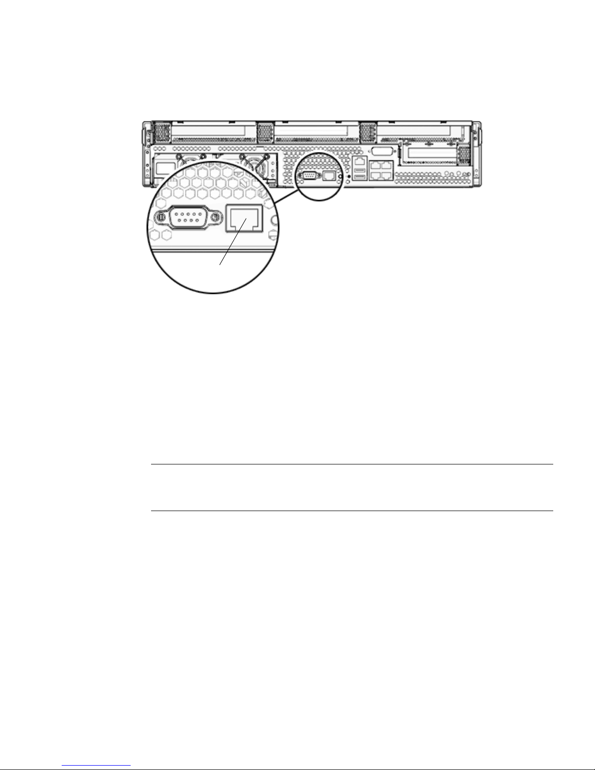
SER MGT
FIGURE 5-3 System Controller Serial Connection
● Connect a Category 5 cable from the SC serial management port to the terminal
device.
▼ To Connect the SC Network Management Port
The SC network management port is marked NET MGT. It is the RJ-45 port above
the rear USB ports.
Note – This port is not operational until you configure the network settings
(through the serial management port), as detailed in “To Configure the System
Controller Network Management Port” on page 81.
Chapter 5 Cabling the Server 71
Page 88
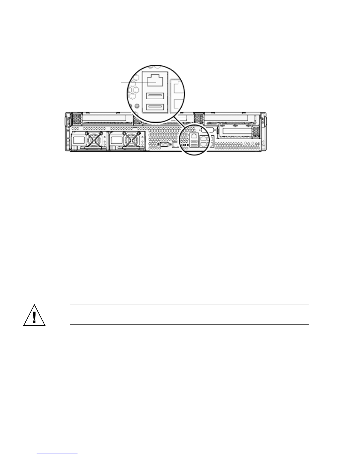
NET MGT
FIGURE 5-4 System Controller Network Connection
● Connect a Category 5 cable from your network switch or hub to the Network
Management Port.
Input Power Cables
Note – Finish the hardware procedures in this chapter, but do not attach the input
power cables yet.
Powering on the server for the first time requires special preparation and
procedures. For example, if you have not prepared a display before connecting the
input power cables, system messages might be lost. You are instructed to connect the
server to input power in “Powering On the Server for the First Time” on page 77.
Caution – The server goes into Standby mode and the system controller initializes
as soon as the input power cables are connected to the power source.
TTYA Serial Port
The TTYA serial port connector uses a DB-9 connector (item 1 in FIGURE 5-5). Use this
port for general-purpose serial data transfers. This port is not connected to the SC
serial management port.
72 Netra T2000 Server Installation Guide • September 2006
Page 89
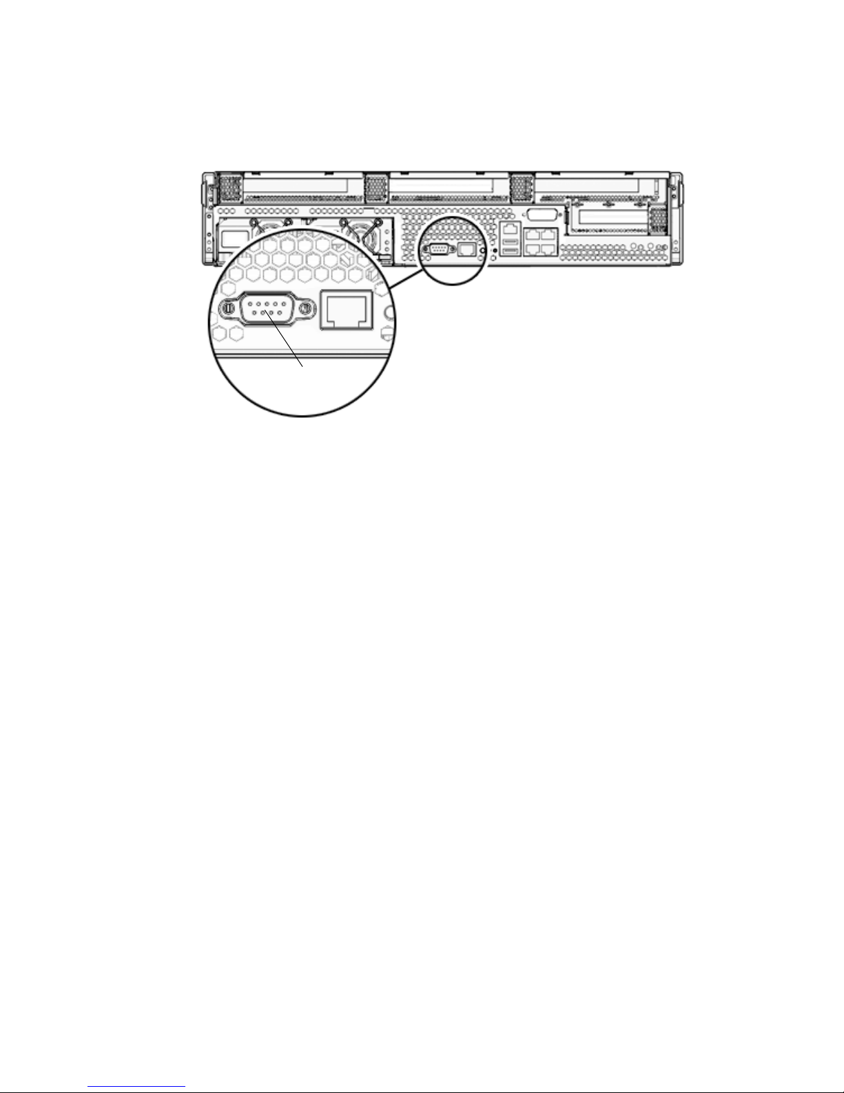
Serial port (TTYA)
FIGURE 5-5 Serial Port
Use a null modem cable or an adapter to perform the crossovers given for each
connector.
■ If connecting to a serial port on a personal computer, use Sun adapter part
number 530-3100-01.
■ If connecting to a Sun workstation or server, use Sun adapter part number 530-
2889-03.
USB Ports
Two Universal Serial Bus (USB) ports are provided on the server. USB ports 0 and 1
are located on the rear of the chassis (
FIGURE 5-6).
Chapter 5 Cabling the Server 73
Page 90
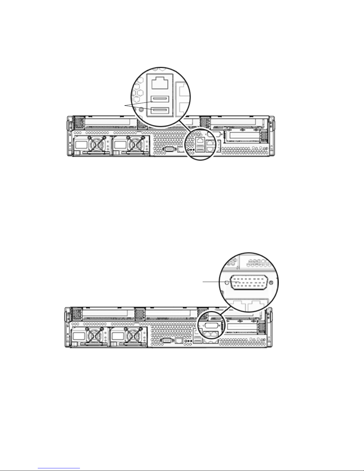
USB ports
FIGURE 5-6 USB Ports
Alarm Port
The server has a dry-contact alarm port to support telco applications.
Alarm port
FIGURE 5-7 Alarm Port
74 Netra T2000 Server Installation Guide • September 2006
Page 91
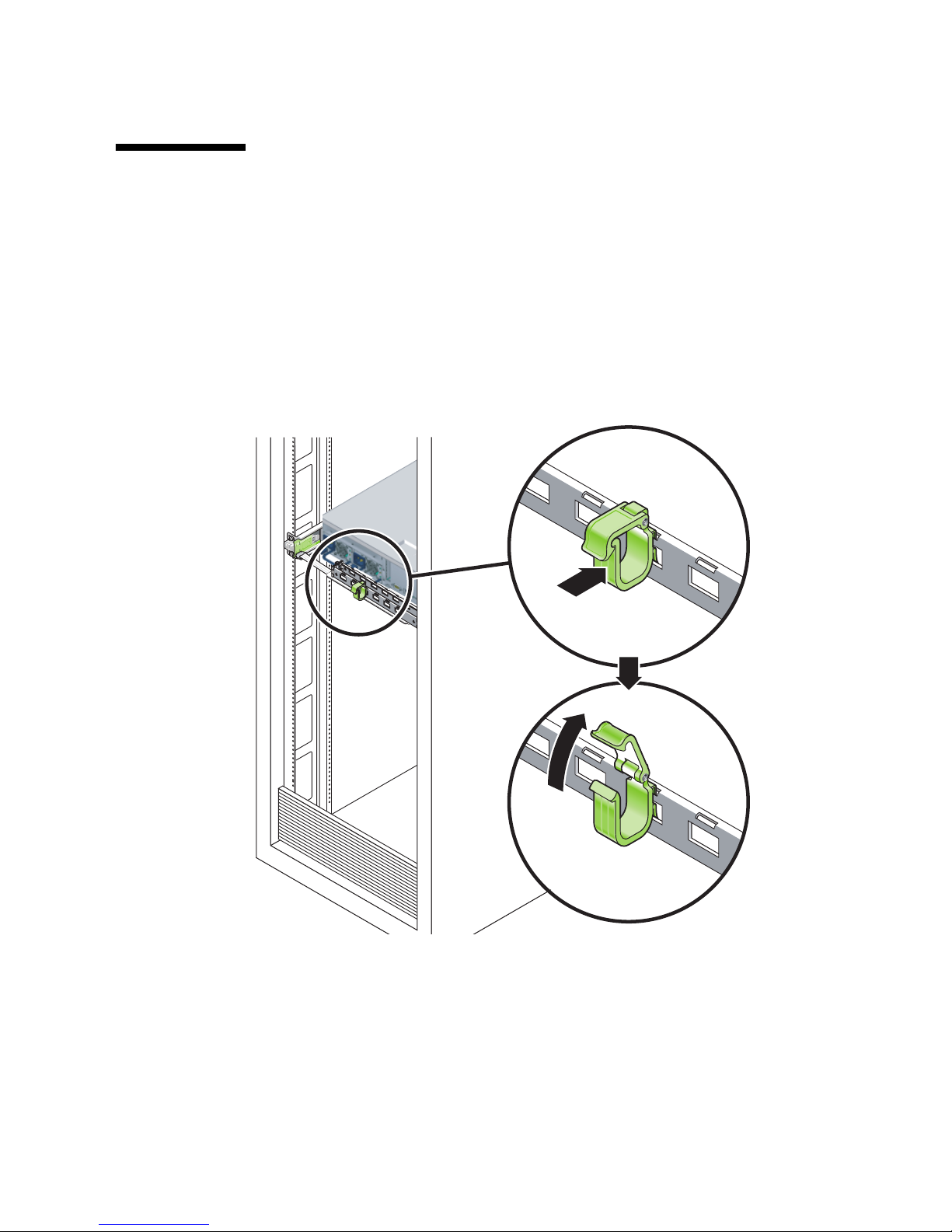
Managing Cables With the CMA
▼ To Open and Close a Cable Clip
1. To open a cable clip, press the front of the cable clip and lift the hinged top.
2. Route cables through the clip, then press the top of the cable clip to lock.
FIGURE 5-8 Opening a Cable Clip
Chapter 5 Cabling the Server 75
Page 92
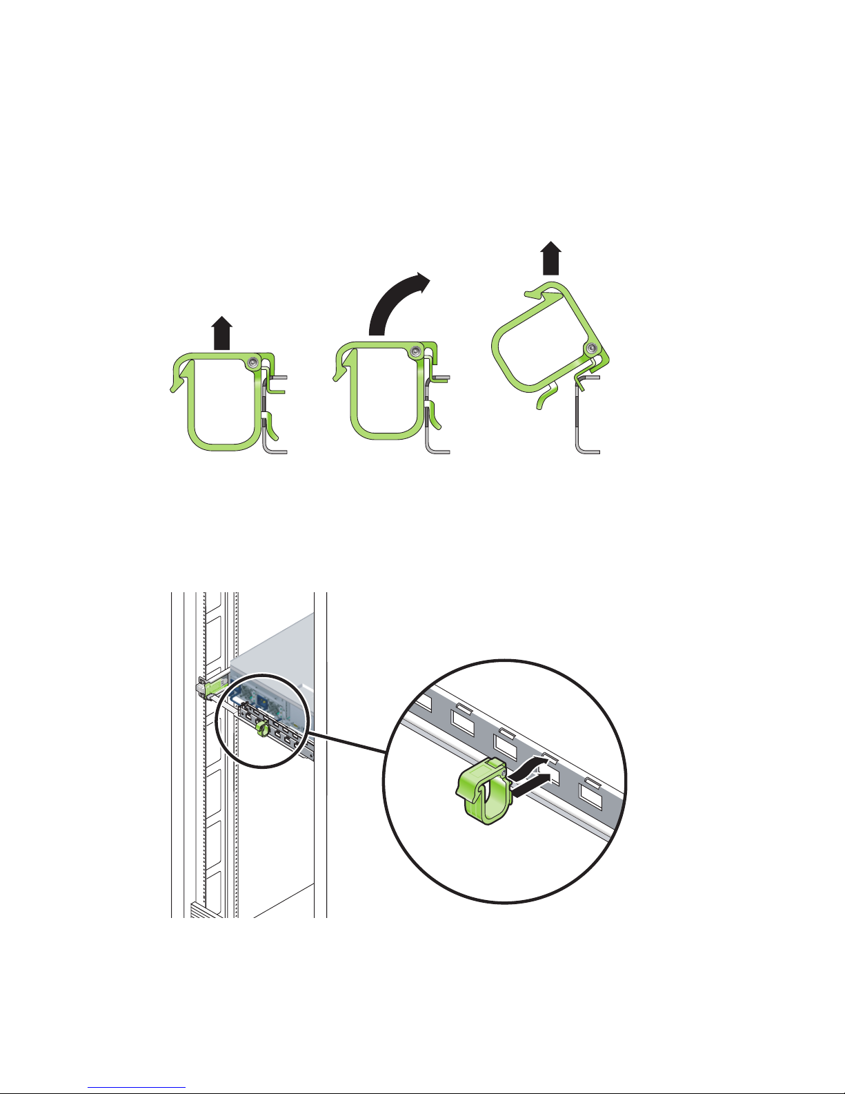
▼ To Move a Cable Clip
1. To remove a cable clip from the CMA arm, lift the cable clip approximately 3/8 in.
(10 mm) to free the lower clip lock, then rotate the entire clip about 90 degrees to
free the upper clip lock.
FIGURE 5-9 Removing a Cable Clip
2. To insert a cable clip, position the upper and lower clip locks in the slots of the
CMA arm, then press the clip down approximately 3/8 in. (10 mm).
FIGURE 5-10 Mounting or Moving a Cable Clip
76 Netra T2000 Server Installation Guide • September 2006
Page 93
CHAPTER
6
Powering On the Server
This chapter includes instructions for booting the server and for enabling the system
controller network management port.
The following topics are discussed:
■ “Powering On the Server for the First Time” on page 77
■ “Enabling the System Controller Network Management Port” on page 80
■ “Logging Into the System Controller” on page 80
■ “Using the System Controller for Common Operations” on page 86
■ “Booting the Solaris Operating System” on page 89
Powering On the Server for the First
Time
Tip – The serial terminal or a terminal emulator should be connected before you
connect the power cables, or you will not see the system messages. The server goes
into Standby mode and the ALOM system controller initializes as soon as the input
power cables are connected to the power source.
Note – If you are not logged in, ALOM times out after 60 seconds and reverts to the
system console. For more information, refer to the ALOM CMT 1.2 Guide.
The system controller runs on the 3.3v standby voltage. As soon as power is
connected to the server, the system controller powers on, runs diagnostics, and
initializes the ALOM firmware.
77
Page 94
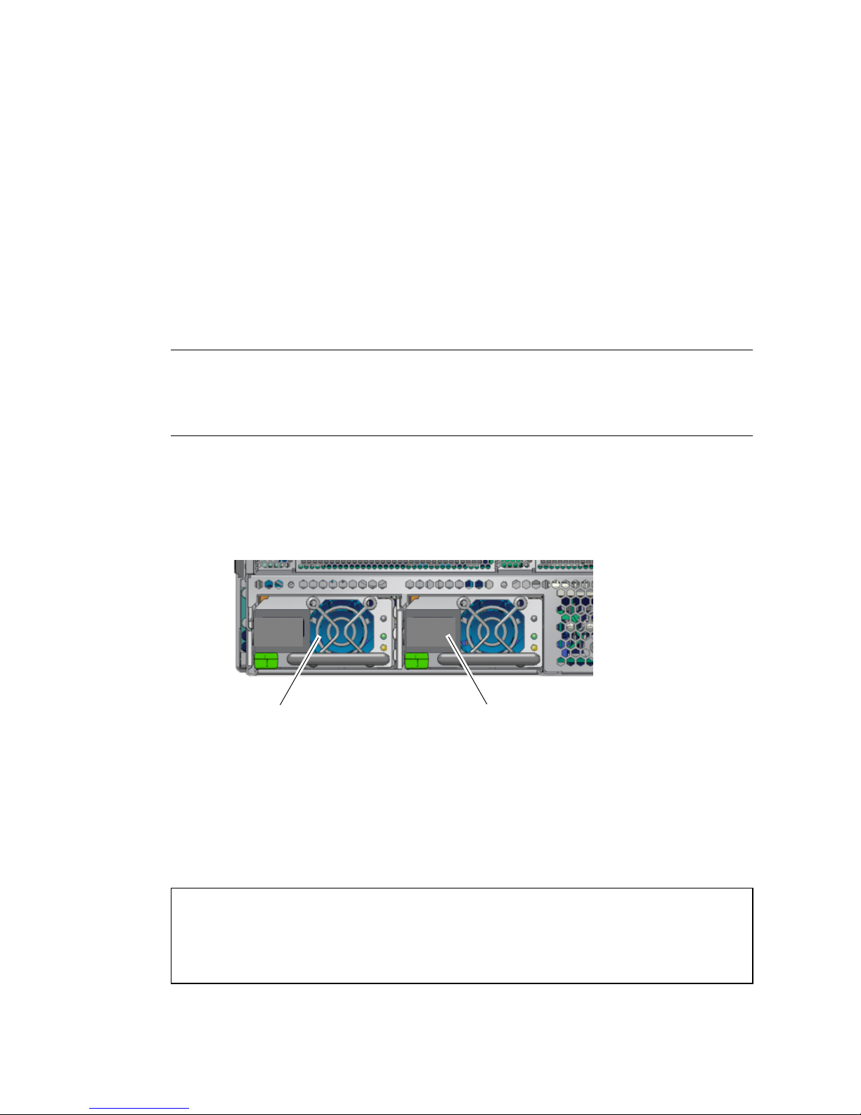
▼ To Power On the Server for the First Time
1. If you have not already done so, connect a terminal or a terminal emulator (PC or
workstation) to the SC serial management port.
Configure the terminal or terminal emulator with these settings:
■ 9600 baud
■ 8 bits
■ No parity
■ 1 Stop bit
■ No handshaking
Note – When you power on the server for the first time and you do not have a
terminal or terminal emulator (PC or workstation) connected to the SC serial
management port, you will not see system messages. The display disappears after
about 60 seconds.
2. Turn on the terminal or terminal emulator, if it is not already turned on.
3. Connect the input power cables to Power Supply 0 and Power Supply 1, and
watch the terminal for system messages.
Power supply 0 Power supply 1
FIGURE 6-1 Rear Panel Power Connectors
After the system controller boots, the system controller login prompt is displayed on
the serial console. The following example shows partial output from the system
controller boot sequence leading to the login prompt.
CODE EXAMPLE 6-1 Sample System Controller Output
ALOM POST 1.0
Dual Port Memory Test, PASSED.
78 Netra T2000 Server Installation Guide • September 2006
Page 95

CODE EXAMPLE 6-1 Sample System Controller Output (Continued)
TTY External - Internal Loopback Test
TTY External - Internal Loopback Test, PASSED.
TTYC - Internal Loopback Test
TTYC - Internal Loopback Test, PASSED.
TTYD - Internal Loopback Test
TTYD - Internal Loopback Test, PASSED.
....................
Full VxDiag Tests - PASSED
Status summary - Status = 7FFF
VxDiag - - PASSED
POST - - PASSED
LOOPBACK - - PASSED
I2C - - PASSED
EPROM - - PASSED
FRU PROM - - PASSED
ETHERNET - - PASSED
MAIN CRC - - PASSED
BOOT CRC - - PASSED
TTYD - - PASSED
TTYC - - PASSED
MEMORY - - PASSED
MPC885 - - PASSED
Please login:
Chapter 6 Powering On the Server 79
Page 96
Enabling the System Controller Network
Management Port
The system controller network management port is not operational until you
configure network settings for the system controller. Configure the system controller
in this order:
1. After the system controller boots, access the ALOM command line interface
through the serial management port. See “To Log Into the System Controller
Using the Serial Management Port” on page 80.
2. Configure the system controller. See “To Configure the System Controller
Network Management Port” on page 81.
3. Enable the new values by resetting the system controller. See “To Reset the
System Controller” on page 84.
You can now use the SP network management port at any time to access the system
controller. See “To Log Into the System Controller Using the Network Management
Port” on page 85.
Logging Into the System Controller
If you are powering on the server for the first time after installation, use the system
controller serial port to power on the server and run POST. See “To Log Into the
System Controller Using the Serial Management Port” on page 80.
If the network management port has already been configured, you can use it instead
of the serial management port. See “To Log Into the System Controller Using the
Network Management Port” on page 85.
▼ To Log Into the System Controller Using the
Serial Management Port
After the system controller boots, you can access the ALOM command-line interface
to configure and manage the server.
80 Netra T2000 Server Installation Guide • September 2006
Page 97
The sc prompt is displayed the first time the system controller is booted. The default
configuration provides an ALOM user account called admin. There is no default
password, so you must create a password using the system controller (sc)
password command.
1. If this is the first time the server has been powered on, use the password
command to set the admin password.
.........................
TTYD - - PASSED
TTYC - - PASSED
MEMORY - - PASSED
MPC885 - - PASSED
sc> password
password: Changing password for admin
Setting password for admin.
New password: new-password
Re-enter new password: new-password
sc>
After the admin password has been set, on subsequent reboots, the sc login prompt
is displayed.
2. Enter admin for the login name followed by your password.
TTYD - - PASSED
TTYC - - PASSED
MEMORY - - PASSED
MPC885 - - PASSED
Please login: admin
Please Enter password: password
(Press Return twice)
sc>
▼ To Configure the System Controller Network
Management Port
To access the system controller using the network for the first time, you must first
configure the SC network management port through the SC serial management port.
Set these network parameters according to the specific details of your network
configuration:
Chapter 6 Powering On the Server 81
Page 98
■ netsc_ipnetmask – Netmask for the system controller subnet
■ netsc_ipaddr – IP address of the system controller
■ netsc_ipgateway – IP address of the gateway for the subnet
■ if_network – Specifies whether the SC is on the network or not
To configure these parameters you must use the setsc command. The usage is:
setsc parameter
1. Set the netmask for the system controller.
sc> setsc netsc_ipnetmask 255.255.255.0
This example uses 255.255.255.0 to set the netmask. Your network environment
subnet might require a different netmask. Use a netmask number most appropriate
to your environment.
2. Set the IP address for the system controller.
sc> setsc netsc_ipaddr service-processor-IPaddr
3. Set the IP address for the system controller gateway.
sc> setsc netsc_ipgateway gateway-IPaddr
4. Set the if_network parameter to true.
sc> setsc if_network true
5. Use the showsc command to verify that the parameters were set correctly.
The showsc command displays all the configuration parameters and their values, as
listed in
TABLE 6-1.
82 Netra T2000 Server Installation Guide • September 2006
Page 99

Note – The highlighted parameters must be set according to the specific details of
your network configuration for the network management port to function properly.
TABLE 6-1 Sample Configuration Parameter Setting
Parameter Sample Value
netsc_enetaddr 00:03:ba_81:2d_02
if_network true
if_modem false
if_emailalerts false
sys_autorestart xir
sys_xirtimeout 900
netsc_tpelinktest true
netsc_dhcp false
netsc_ipaddr 129.148.40.30
netsc_ipnetmask 255.255.255.0
netsc_ipgateway 129.148.40.254
mgt_mailhost
mgt_mailalert
sc_customerinfo
sc_escapechars #.
sc_powerondelay false
sc_powerstatememory false
sc_clipasswdecho true
sc_cliprompt sc
sc_clitimeout 0
sc_clieventlevel 2
sc_backupuserdata true
sys_eventlevel 2
sys_confighost wgs40-80
sys_configip 129.148.40.80
ser_baudrate 9600
ser_parity none
Chapter 6 Powering On the Server 83
Page 100
TABLE 6-1 Sample Configuration Parameter Setting (Continued)
Parameter Sample Value
ser_stopbits 1
ser_data 8
netsc_enetaddr 00:03:ba:81:2d:02
sys_hostname
sys_enetaddr 00:03:ba:81:2c:f9
▼ To Reset the System Controller
After all of the configuration parameters are set, you must reset the system controller
for the new values to take affect.
● Issue the resetsc command.
You are prompted to confirm that you want to reset the system controller. Reply y
when prompted.
sc> resetsc
Are you sure you want to reset the SC [y/n]? y
User Requested SC Shutdown
Note – You can specify the –y flag to the resetsc command and bypass the
confirmation message.
The system controller resets, runs diagnostics, and returns to the login prompt.
ALOM POST 1.0
Dual Port Memory Test, PASSED.
TTY External - Internal Loopback Test
TTY External - Internal Loopback Test, PASSED.
TTYC - Internal Loopback Test
TTYC - Internal Loopback Test, PASSED.
TTYD - Internal Loopback Test
TTYD - Internal Loopback Test, PASSED.
84 Netra T2000 Server Installation Guide • September 2006
 Loading...