


Netra™t 1400/1405 Installation and User’s Guide
Sun Microsystems, Inc.
901 San Antonio Road
Palo Alto, CA 94303-4900 USA
650 960-1300 Fax 650 969-9131
Part No. 806-0575-10
September 1999, Revision A
Send comments about this document to: docfeedback@sun.com

Copyright 1999Sun Microsystems, Inc., 901 San Antonio Road • Palo Alto, CA 94303 USA. All rights reserved.
This product or document is protectedby copyright and distributed under licenses restrictingits use, copying, distribution, and
decompilation. No part of this productor document may be reproduced in any form by any means without prior writtenauthorization
of Sun and its licensors, if any.Third-party software, including font technology, is copyrighted and licensed fromSun suppliers.
Parts of the product may be derived from Berkeley BSD systems, licensed from the University of California. UNIX is a registered trademark in
the U.S. and other countries, exclusively licensed through X/Open Company, Ltd.
Sun, Sun Microsystems,the Sun logo, AnswerBook, Java, the Java Coffee Cup, Netra and Solaris aretrademarks, registered trademarks, or
service marks of Sun Microsystems,Inc. in the U.S. and other countries. All SPARCtrademarksare used under license and are trademarks or
registeredtrademarks of SPARCInternational,Inc. in the U.S. and other countries. Productsbearing SPARCtrademarks are based upon an
architecturedeveloped by Sun Microsystems, Inc.
The OPEN LOOK and Sun™ Graphical User Interface was developedby Sun Microsystems, Inc. for its users and licensees. Sun acknowledges
the pioneering effortsof Xerox in researching and developing the concept of visual or graphical user interfaces for the computer industry. Sun
holds a non-exclusive license fromXerox to the Xerox Graphical User Interface, which license also covers Sun’s licensees who implement OPEN
LOOK GUIs and otherwise comply with Sun’s written license agreements.
RESTRICTEDRIGHTS: Use, duplication, or disclosure by the U.S. Government is subject to restrictions of FAR52.227-14(g)(2)(6/87) and
FAR52.227-19(6/87),or DFAR 252.227-7015(b)(6/95) and DFAR227.7202-3(a).
DOCUMENTATION ISPROVIDED “AS IS” AND ALL EXPRESS OR IMPLIED CONDITIONS, REPRESENTATIONSAND WARRANTIES,
INCLUDING ANY IMPLIED WARRANTY OF MERCHANTABILITY, FITNESS FOR A PARTICULAR PURPOSE OR NONINFRINGEMENT, ARE DISCLAIMED, EXCEPT TO THE EXTENT THAT SUCH DISCLAIMERS ARE HELD TO BE LEGALLY INVALID.
Copyright 1999 Sun Microsystems, Inc., 901 San Antonio Road • Palo Alto, CA 94303 Etats-Unis. Tousdroitsréservés.
Ce produit ou document est protégépar un copyright et distribué avecdes licences qui en restreignentl’utilisation, la copie, la distribution, et la
décompilation. Aucune partie de ce produit ou document ne peut être reproduitesous aucune forme, par quelque moyen que ce soit, sans
l’autorisation préalable et écrite de Sun et de ses bailleurs delicence, s’ily ena. Le logiciel détenu par des tiers, et qui comprend la technologie
relativeaux polices de caractères, est protégé parun copyright et licencié par des fournisseurs de Sun.
Des parties de ce produitpourront être dérivéesdes systèmes Berkeley BSD licenciés par l’Université de Californie. UNIX est une marque
déposée auxEtats-Unis et dans d’autres pays et licenciée exclusivement par X/Open Company, Ltd.
Sun, Sun Microsystems,le logo Sun, AnswerBook, Java, le logo Jave Coffee Cup, Netra, et Solaris sont des marques de fabrique ou des marques
déposées, ou marquesde service, de Sun Microsystems, Inc. aux Etats-Unis et dans d’autrespays. Toutesles marquesSPARCsontutilisées sous
licence et sont des marquesde fabrique ou des marques déposéesde SPARCInternational, Inc. aux Etats-Unis et dans d’autres pays. Les
produitsportant les marques SPARCsont basés sur une architecturedéveloppée par Sun Microsystems, Inc.
L’interfaced’utilisationgraphique OPEN LOOK et Sun™ a été développée par Sun Microsystems, Inc. pour ses utilisateurs et licenciés. Sun
reconnaîtles efforts de pionniers de Xerox pourla recherche et le développement du concept des interfaces d’utilisation visuelle ou graphique
pour l’industrie de l’informatique. Sun détient une licence non exclusive deXerox sur l’interface d’utilisation graphique Xerox, cette licence
couvrant également les licenciés de Sun qui mettent en place l’interface d’utilisation graphique OPEN LOOK et qui en outre se conforment aux
licences écrites de Sun.
CETTE PUBLICATION EST FOURNIE "EN L’ETAT" ET AUCUNE GARANTIE, EXPRESSE OU IMPLICITE, N’EST ACCORDEE, Y
COMPRIS DES GARANTIES CONCERNANT LA VALEUR MARCHANDE, L’APTITUDE DE LA PUBLICATION A REPONDRE A UNE
UTILISATION PARTICULIERE, OU LE FAIT QU’ELLE NE SOIT PAS CONTREFAISANTE DE PRODUIT DE TIERS. CE DENI DE
GARANTIE NE S’APPLIQUERAIT PAS, DANS LA MESURE OU IL SERAIT TENU JURIDIQUEMENT NUL ET NON AVENU.
Please
Recycle

Contents
Part I. Installation
1. Product Overview 1
System Unit Features 1
2. Installing the System 5
Environmental Considerations 5
Dimensions 5
Forced Air Cooling Requirements 6
Mechanical Considerations 7
Removing the Sacrificial Shipping Plates 7
Mounting Flanges 8
3. Installing the Electrical Supply 11
System Switch 11
Connectors 12
DC Source Site Requirements 12
Overcurrent Protection Requirements 13
Connection Materials 13
Grounding 13
DC Supply and Ground Conductor 13
iii

Power and Grounding Connections 14
AC Source Site Requirements 23
Chassis Enclosure Grounding 23
4. External I/O Connections 27
Connector Layout 27
Parallel Interface 29
Serial Connectors 30
Twisted-Pair Ethernet (TPE) Connector 31
TPE Cable-Type Connectivity 31
SCSI Connector 32
SCSI Implementation 33
SCSI Cabling and Configuration 34
SCSI Cabling Procedure 34
SCSI-2 (Fast Wide SCSI) External Devices 35
Alarms Ports 36
5. Installing the Alarms Software 39
Local Installation 39
SunVTS Software 41
6. Replacing the Air Filter 43
Part II. User Guide
7. LEDs and Controls 47
LEDs 47
Netra t 1400 48
Netra t 1405 49
System ON/STBY Switch 50
iv Netra t 1400/1405 Installation and User’s Guide • September 1999

8. System Start-up and Operation 55
9. Open Boot PROM 57
NVRAM Configuration Parameters 57
Emergency Procedures 59
Running Diagnostics 59
New Devices in the OBP Device Tree 60
10. Using LOMlite 61
LOMlite Functionality 61
Diagnosing PSU Faults 62
Diagnosing Fan Faults 62
Power 63
Serial Connection 63
Controlling LOMlite 64
Configuring LOMlite 65
Fault LED 65
System Watchdog 66
System Monitoring 66
11. System Shut-down 67
Index 69
Contents v

vi Netra t 1400/1405 Installation and User’s Guide • September 1999

Figures
FIGURE 1-1 Netra t 1400 System Unit Front View 3
FIGURE 1-2 Netra t 1400 System Unit Rear View 3
FIGURE 1-3 Netra t 1405 System Unit Front View 4
FIGURE 1-4 Netra t 1405 System Unit Rear View 4
FIGURE 2-1 Netra t 1400/1405 Airflow 6
FIGURE 2-2 Sacrificial Shipping Plates 7
FIGURE 2-3 Netra t 1400/1405 Flange Options and Dimensions 8
FIGURE 2-4 Flange Mount Assembly 10
FIGURE 3-1 DC input connector 14
FIGURE 3-2 Strain Relief Housings 14
FIGURE 3-3 Cage Clamp Operating Lever 15
FIGURE 3-4 Power Connector on the DC Power Supply 15
FIGURE 3-5 Stripping the Insulation From the Wire 16
FIGURE 3-6 Opening the DC Connector Cage Clamp Using the Cage Clamp Operating Lever 17
FIGURE 3-7 Assembling the DC Input Power Cable 18
FIGURE 3-8 Inserting the Bottom Portion of the Strain Relief Housing 19
FIGURE 3-9 Routing the Wires Out of the Bottom Portion of the Strain Relief Housing 19
FIGURE 3-10 Securing the Wires to the Strain Relief Housing 20
FIGURE 3-11 Assembling the Strain Relief Housing 21
Figures vii

FIGURE 3-12 Connecting the DC Power Cable to the Netra DC Power Supply 22
FIGURE 3-13 System Power-On (Front Panel) 24
FIGURE 3-14 System Power-off (Front Panel) 26
FIGURE 4-1 Back Panel Connectors 28
FIGURE 4-2 DB-25 Parallel Connector 29
FIGURE 4-3 DB-25 Serial Connectors 30
FIGURE 4-4 RJ45 TPE Socket 31
FIGURE 4-5 68-Pin SCSI Connector 32
FIGURE 4-6 Connecting External Mass Storage Devices 35
FIGURE 4-7 DB-15 (Male) Alarms Service Port Connector 36
FIGURE 4-8 RJ45 Lights Out Management Serial Connector 37
FIGURE 6-1 Replacing the Air Filter 43
FIGURE 7-1 Netra t 1400 System LEDs 48
FIGURE 7-2 Netra t 1405 System LEDs 49
FIGURE 7-3 System Power-On (Front Panel) 50
FIGURE 7-4 System Power-Off (Front Panel) 52
viii Netra t 1400/1405 Installation and User’s Guide • September 1999

Tables
TABLE 2-1 Optional Mounting Flange Kits 9
TABLE 3-1 DC Power Requirements 12
TABLE 4-1 Parallel Connector Pinout 29
TABLE 4-2 Serial Connector Pinout, RS423/RS232 30
TABLE 4-3 TPE Connector Pinout 31
TABLE 4-4 TPE STP-5 Cable Lengths 32
TABLE 4-5 68-Pin SCSI Connector Pinout 32
TABLE 4-6 Determining SCSI Bus Length 34
TABLE 4-7 Alarms Service Port Connector Pinout 36
TABLE 4-8 Lights Out Management Serial Connector Pinout 37
TABLE 7-1 Netra t 1400 System LED Functions 48
TABLE 7-2 Netra t 1405 System LED Functions 49
TABLE 9-1 NVRAM Configuration Parameters 57
TABLE 10-1 LOMlite Commands 64
TABLE 10-2 LOMlite Configuration File Parameters 65
TABLE 11-1 Commands for Shutting Down the System 67
Tables ix

x Netra t 1400/1405 Installation and User Guide • September 1999

Preface
This manual comprises two parts:
■ Part I, Installation, describes the installation and basic maintenance procedures for
the Netra t 1400 and Netra t 1405 systems and is intended to be read by
installation engineers, software support engineers and service personnel.
■ Part II, User Guide, provides information about the system administration and
software operation of the Netra t 1400/1405 and is intended for system users and
administrators.
How This Book Is Organized
Chapter 1 describes the key features of the Netra t 1400/1405 computer system.
Chapter 2 covers the environmental and site requirements.
Chapter 3 describes the electrical supply requirements.
Chapter 4 provides information about external I/O connectors.
Chapter 5 describes the steps required to install a software release.
Chapter 6 describes how to replace the air filters.
Chapter 7 provides a description of the power on and power off procedures, the
systes LEDs and connectors.
Chapter 8 describes the procedure for booting the Netra t 1400/1405.
Chapter 9 explains the changes that have been made to the Open Boot Prom (OBP)
for the Netra t 1400/1405.
Chapter 10 describes the LOMlite facility.
Chapter 11 describes the procedure for shutting down the Netra t 1400/1405 system
cleanly and safely.
xi

Typographic Conventions
TABLEP-1 Typographic Conventions
Typeface Meaning Examples
AaBbCc123 The names of commands, files,
and directories; on-screen
computer output
AaBbCc123
AaBbCc123 Book titles, new words or terms,
What you type, when
contrasted with on-screen
computer output
words to be emphasized
Edit your .login file.
Use ls -a to list all files.
% You have mail.
% su
Password:
Read Chapter 6 in the User’s Guide.
These are called class options.
You must be superuser to do this.
Command-line variable; replace
with a real name or value
To delete a file, type rm filename.
Shell Prompts
TABLEP-2 Shell Prompts
Shell Prompt
C shell machine_name%
C shell superuser machine_name#
Bourne shell and Korn shell $
Bourne shell and Korn shell superuser #
xii Netra t 1400/1405 Installation and User’s Guide • September 1999

Related Documentation
TABLEP-3 Related Documentation
Application Title Part Number
Compliance
Safety
Service
System Reference
Netra t 1400/1405 Compliance and Safety
Manual
Netra t 1400/1405 Service and System
Reference Manual
806-0574-10
806-0576-10
Note – It is essential that you read the Netra t 1400/1405 Compliance and Safety
manual before proceeding.
Sun Welcomes Your Comments
We are interested in improving our documentation and welcome your comments
and suggestions. You can email your comments to us at:
docfeedback@sun.com
Please include the part number of your document in the subject line of your email.
xiii

xiv Netra t 1400/1405 Installation and User’s Guide • September 1999

PART
I Installation


CHAPTER
1
Product Overview
The Netra t 1400/1405 computer system is a one- to four-processor device that uses
the family of UltraSPARC™ II processors. Housed within a rack-mounting
enclosure, the Netra t 1400/1405 provides the following:
■ High performance processors
■ Extensive I/O expansion and a wide range of options
■ Modular internal design
■ High performance disk, system, memory and I/O subsystems
■ High performance peripheral component interconnect (PCI) I/O
■ Redundant hot swap power supply units
■ Rack mounting options available
■ Alarms functionality for remote management
The Netra t 1400 is powered by –48V / –60V DC supplies. The Netra t 1405 is
powered by standard AC supplies. This is the only difference between the systems.
FIGURE 1-1 and FIGURE 1-2 on page 3 illustrate the front and rear, respectively, of the
Netra t 1400;
FIGURE 1-3 and FIGURE 1-4 on page 4 illustrate the front and rear,
respectively, of the Netra t 1405. The following sections provide a brief description of
the Netra t 1400/1405 I/O devices and a detailed overview of the system unit
features.
System Unit Features
System unit components are housed in a rack-mounting enclosure. Overall enclosure
dimensions (width x depth x height) are 431.8mm x 477.3mm x 264mm (17.00in. x
18.79in. x 10.39in. (6U)). System unit electronics are contained on a single printed
circuit board (motherboard). The motherboard contains the CPU module(s), memory,
system control application-specific integrated circuits (ASICs) and I/O ASICs.
1

The system unit has the following features:
■ Rack mounting enclosure with n + 1 redundant hot swap –48VDC / –60VDC
(Netra t 1400) or AC (Netra t 1405) power supplies
■ support for up to four modular 440MHz UltraSPARC II processors with
4Mbyte cache
■ UltraSPARC Port Architecture (UPA) coherent memory interconnect
■ use of DIMMs, with an interleaved memory system. Each pair of DIMM slots
(four rows of two pairs each) accepts 64 or 256Mbyte DIMM modules. Populating
with two pairs of identical capacity DIMMs enables the memory controller to
interleave and overlap, providing optimal system performance. There are a total
of 16 DIMM slots supplying a minimum of 256Mbyte
(4 x 64Mbyte) and a maximum of 4Gbyte (16 x 256Mbyte) of memory.
■ Four PCI slots:
■ two 33MHz, 64- or 32-bit, 5VDC slots
■ one 33MHz 32-bit only 5VDC slot
■ one 66MHz or 33MHz, 64- or 32-bit, 3.3VDC slot
Universal PCI cards can be used in any of the four PCI slots.
■ 10/100 Megabit per second (Mbps) Ethernet
■ 40Mb/s Fast-20 (UltraSCSI) disk subsystem supporting up to four 18MB disk
drives
■ Two RS232/423 DB-25 serial ports (asynchronous protocols)
■ Parallel port
■ External Fast-20 (UltraSCSI) 68-pin port
■ Up to two SCSI removable media drives (CD-ROM or DAT or both)
■ Alarms card implementing Lights Out Management
2 Netra t 1400/1405 Installation and User’s Guide • September 1999

1400
FIGURE 1-1 Netra t 1400 System Unit Front View
FIGURE 1-2 Netra t 1400 System Unit Rear View
Chapter 1 Product Overview 3

1405
FIGURE 1-3 Netra t 1405 System Unit Front View
FIGURE 1-4 Netra t 1405 System Unit Rear View
4 Netra t 1400/1405 Installation and User’s Guide • September 1999

CHAPTER
2
Installing the System
Before you install the system, confirm that the correct power supply is available.
Refer to Chapter 3, "Installing the Electrical Supply", for further information.
Environmental Considerations
The system can be installed in an environment with the following specific parameter
ranges:
■ Ambient temperature
■ operating: 5˚ to 40˚C
■ exceptional operating limit: –5˚ to 55˚C
■ storage: –40˚ to 70˚C
■ Relative humidity
■ operating: 5 to 85% non-condensing
■ storage: 10 to 95% non-condensing
■ Elevation
■ operating: –300 to +3000 meters
■ storage: –300 to +12000 meters
1,2
3
Dimensions
■ Height: 264mm (10.39in.) 6U nominal
■ Width: 431.8mm (17.00in.)
■ Depth: 477.3mm (18.79in.)
■ Weight (unpackaged): maximum 32kg (71lb)
1. Error-freeoperation of the removable media devices is from 0°to 40°C.
2. No more than 96 hours duration at extremesand at elevations less than 1800m.
3. Subject to a maximum absolute humidity of 0.024kg of water per kg of dry air.
5

Flanges can be fitted to accommodate the equipment in 19-inch, 23-inch 24-inch and
600-mm racks (see
FIGURE 2-3 on page 8).
Forced Air Cooling Requirements
1. Adequate airflow through the host equipment frame must be ensured.
2. The air is drawn through the front of the Netra t 1400/1405 enclosure and
expelled from the rear of the enclosure.
3. The inlet and exhaust ventilation areas must be a minimum of 200 sq cm each.
FIGURE 2-1 Netra t 1400/1405 Airflow
4. To maintain adequate airflow we strongly recommend that you inspect and, if
necessary, replace the air filter on a regular basis. See Chapter 6, "Replacing the
Air Filter", for further information.
5. If the Netra t 1400/1405 computer system is fully enclosed by its host equipment
rack, the host rack must have ventilation openings in the front door. This permits
unrestricted access to an external air source.
6 Netra t 1400/1405 Installation and User’s Guide • September 1999

Mechanical Considerations
Caution – The Netra t 1400/1405 system, when fully loaded, can weigh up to 38kg
(84lb); hence mechanical assistance may be required if installing a fully-loaded unit.
Removing the Sacrificial Shipping Plates
Where possible, the four sacrificial shipping plates should only be removed after
mounting the system in a rack. Remove the four M5 screws securing each plate to
the system.
FIGURE 2-2 Sacrificial Shipping Plates
Note – Please retain the plates and system packaging for future use.
Chapter 2 Installing the System 7

Mounting Flanges
The Netra t 1400/1405 chassis has been designed for a wide variety of mounting
options and rack sizes. One set of 19-inch flanges (four) and handles (two) is
included with each system. Mounting flanges to suit 23-inch, 24-inch or 600-mm
nominal frame widths can be ordered as required:
442.3442.3
325.45325.45
190.55190.55
146.1146.1
36.7536.75
195.45195.45
24.524.5
44.4544.45
DIMENSION 'A'DIMENSION 'A'
471.2471.2 ))((
473.8473.8
356.95356.95
226.95226.95
5656
DIMENSION 'A'DIMENSION 'A'
471.2471.219" FLANGES19" FLANGES
572.1572.123" FLANGES23" FLANGES
596.6596.624" FLANGES24" FLANGES
519519600mm FLANGES600mm FLANGES
5.35.35.35.3
FIGURE 2-3 Netra t 1400/1405 Flange Options and Dimensions
8 Netra t 1400/1405 Installation and User’s Guide • September 1999

Optional Components
TABLE2-1 Optional Mounting Flange Kits
Mounting Option Part Number
19-inch configuration X7071A
23-inch configuration X7072A
24-inch configuration X7073A
600-mm configuration X7074A
Select the mounting position most suitable for the rack type (see FIGURE 2-3). There
are four fixing locations provided on a Netra t 1400/1405; one at the front, two in the
centre and one at the rear. If the front location is required, first ensure that, if fitted,
the sacrificial shipping plates have been removed (see
possible, the four sacrificial shipping plates should only be removed after mounting
the system in a rack.
Fit the mounting flanges in the selected position using the four M5 countersunk
screws per flange provided with the mounting kit and a Phillips No. 1 screwdriver.
If required, you can fit the supplied handles to the mounting flanges before fitting
flanges to the system or, alternatively, fit them to the mounted flanges.
FIGURE 2-4 on page 10 shows how to connect the Flange Mount assembly to the
Netra t 1400/1405 system.
FIGURE 2-2 on page 7). Where
Chapter 2 Installing the System 9

FIGURE 2-4 Flange Mount Assembly
The chassis must be secured within the rack frame using screws suitable for the
equipment frame. They must be a minimum size of M5 (10/32) depending on the
frame requirement. All screws must be fitted; there are positions provided for a total
of 16 screws (four per flange). The recommended tightening torque value for M5
recess head screws is 4.0Nm (3.0lbf-ft).
Caution – For flange mounted installations, always fit four flanges.
10 Netra t 1400/1405 Installation and User’s Guide • September 1999

CHAPTER
3
Installing the Electrical Supply
This chapter provides information about electrical supply installation.
Note – All supply connections, wiring, wire protection, and wire routing must be
made in accordance with applicable sections and requirements of national electrical
code and local electrical authorities.
System Switch
1400
Caution – The system switch does not isolate the equipment.
The system switch of the Netra t 1400/1405 system functions as a standby device
enabling and disabling the power module outputs. The system switch is a rocker,
momentary switch.
The system does not contain any integral circuit breakers. The system can be isolated
from the power only by using external circuit breakers.
All connections must be broken to isolate the system. To isolate the system, open all
external circuit breakers.
Note – The ON/STBY switch handles low voltage signals only; the high-power
circuits do not pass through this switch.
11

Connectors
1400
1405
1400
The Netra t 1400 has a pair of 3-position Wago connectors per power supply. The
mating connectors are specified in the section “DC Source Site Requirements” on
page 12.
The Netra t 1405 has an IEC 320 appliance coupler for connection to mains power.
The mating connectors are specified in the section “AC Source Site Requirements”
on page 23.
DC Source Site Requirements
TABLE 3-1 DC Power Requirements
Electrical Element Requirement
Voltage -48VDC / -60VDC
Max. operating current 10A @ -48VDC / 12 @ -60VDC
Max. inrush current 24A @ -48VDC / 30A @ -60VDC
1. The DC power supply range is -40 VDC to -75 VDC.
The DC source must be:
■ –48VDC or –60VDC nominal centralized DC power system
■ Electrically isolated from any AC power source
■ Reliably connected to earth (that is, the battery room positive bus is connected to
the grounding electrode)
■ Rated for a minimum of 15A per feed pair
1
Note – The Netra t 1400 must be installed in a restricted access location. Per the intent
of the National Electrical Code, a restricted access location is an area intended for
qualified or trained personnel only and has access controlled by a locking
mechanism, such as a key lock or an access card system.
12 Netra t 1400/1405 Installation and User’s Guide • September 1999

Overcurrent Protection Requirements
■ Overcurrent protection devices must be provided as part of each host equipment
rack.
■ Two 15A single-pole, fast trip, DC-rated circuit breakers (one per ungrounded
supply conductor) must be located in the negative supply conductor between the
DC power source and the Netra t 1400 system.
■ Circuit breakers must not trip when presented with inrush current of 20A lasting
250ms.
Note – Overcurrent devices must meet applicable national and local electrical safety
codes and be approved for the intended application.
Connection Materials
Grounding
■ One Thomas & Betts two-hole lug (part number: 54204-UB) suitable for 8AWG
conductor or UL/CSA approved equivalent having 5/8-inch pitch. Torque value:
3.5Nm maximum. Two M5 studs and cupwasher nuts are supplied on the rear of
the chassis for connection.
■ A Thomas & Betts crimping tool (part number: TBM 5-S), or approved equivalent
is required to secure the lug on to the cable.
■ An earthing bus bar that is near the equipment and easily accessible.
Caution – External filtering and/or surge suppression devices may be required on
!
the power feeds where branch circuit electromagnetic characteristics are unknown.
DC Supply and Ground Conductor
The requirements are:
■ Suitable conductor material: tinned copper only
■ Conductors: 12 AWG maximum (between the Netra t 1400 and circuit breaker).
There are three conductors:
■ -48VDC/-60VDC Supply (pin 1)
■ Ground connection to power supply (pin 2)
■ -48VDC/-60VDC Return (pin 3)
Chapter 3 Installing the Electrical Supply 13
■ System ground conductor: 8 AWG
■ Cable insulation rating: minimum 75˚C, low smoke fume (LSF), flame retardant
■ Cable must conform to GR63CORE fire resistance requirements
■ Branch circuit cable insulation color: per applicable National Electrical Codes
■ Grounding cable insulation color: green/yellow
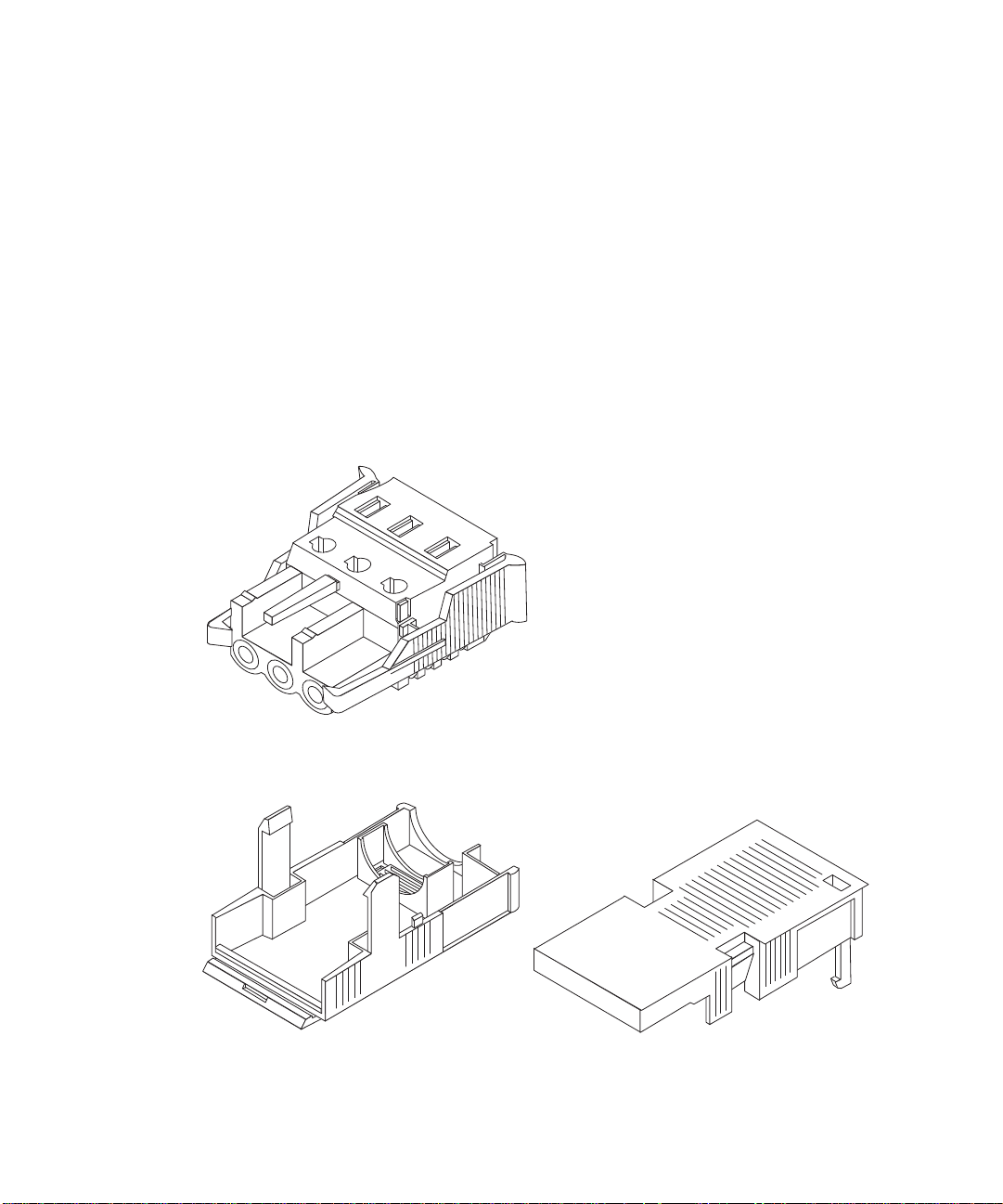
Power and Grounding Connections
The following DC connection materials are provided in the DC input connector kit:
■ Six Wago DC input connectors
■ Six Wago strain relief housings
■ One cage clamp operating lever
■ Six wire ties
FIGURE 3-1 DC input connector
FIGURE 3-2 Strain Relief Housings
14 Netra t 1400/1405 Installation and User’s Guide • September 1999

FIGURE 3-3 Cage Clamp Operating Lever
The following figure shows the power connector on the DC power supply on your
system.
1
2
3
-48VDC/-60VDC Supply -48VDC/-60VDC RTNPSU ground
FIGURE 3-4 Power Connector on the DC Power Supply
Chapter 3 Installing the Electrical Supply 15

▼ To Wire the DC Input Power Connector
1. Turn off power to the DC power source by opening the circuit breakers.
Caution – Do not proceed with these instructions until you have turned off the
power to the DC power source through the circuit breakers.
2. Strip 8mm (0.31 inches) of insulation from each of the wires to be fitted to the connector.
Do not strip more than 8mm (0.31in.) from each wire. Doing so will leave
uninsulated wire exposed from the DC input connector after the assembly is
complete.
8mm (0.31in.)
FIGURE 3-5 Stripping the Insulation From the Wire
3. Using a DC connector from the kit, insert the tip of a cage clamp operating lever
into the rectangular hole directly above the hole in the DC connector where you
want to insert the first wire and press down on the cage clamp operating lever.
This opens the cage clamp for this section of the DC input connector.
16 Netra t 1400/1405 Installation and User’s Guide • September 1999

Top of connector
FIGURE 3-6 Opening the DC Connector Cage Clamp Using the Cage Clamp Operating
Lever
You can also open the DC connector cage clamp by inserting a small slotted
screwdriver into the rectangular hole directly above the hole in the DC connector
where you want to insert the first wire and pressing down on the screwdriver.
Chapter 3 Installing the Electrical Supply 17

4. Feed the stripped end of each wire into the appropriate hole in the DC input
Top of connector
5. Repeat Step 3 and Step 4 for the other two wires to complete the assembly of the
6. If you are not using the optional strain relief housing, secure the wires together
7. Repeat Step 2 through Step 6 to wire the other five DC input power connectors.
connector.
FIGURE 3-7 shows which wires should be inserted into each hole in the DC input
connector.
from -48VDC / -60VDC Return
from ground
from -48VDC / -60VDC Supply
123
FIGURE 3-7 Assembling the DC Input Power Cable
DC input power cable.
with a wire tie.
Note that you will require a separate DC power source for each DC input.
If you need to remove a wire from the DC input connector, insert the cage clamp
operating lever or a small screwdriver into the slot directly above the wire to free the
wire from the cage clamp, and press down (
▼ To Install the Optional Strain Relief Housings
1. Take the DC input connector and insert the bottom portion of the strain relief
housing into the notch on the DC input connector until it snaps into place.
Make sure the strain relief housing snaps into place on the DC input connector; you
will not be able to complete the assembly correctly if the strain relief housing is not
snapped into place.
18 Netra t 1400/1405 Installation and User’s Guide • September 1999
FIGURE 3-6).

FIGURE 3-8 Inserting the Bottom Portion of the Strain Relief Housing
2. Route the three wires coming from the DC power source through the opening at
the end of the bottom portion of the strain relief housing.
FIGURE 3-9 Routing the Wires Out of the Bottom Portion of the Strain Relief Housing
3. Insert the wire tie into the bottom portion of the strain relief housing.
Chapter 3 Installing the Electrical Supply 19

FIGURE 3-10 Securing the Wires to the Strain Relief Housing
4. Loop the wire tie over the wires and back out of the strain relief housing, then
tighten the wire tie to secure the wires to the strain relief housing (
FIGURE 3-10).
5. Lower the three prongs on the top portion of the strain relief housing into the
openings in the DC input connector, then push the top portion and bottom
portion of the strain relief housing together until they snap into place.
20 Netra t 1400/1405 Installation and User’s Guide • September 1999

FIGURE 3-11 Assembling the Strain Relief Housing
The DC input power cables for your system are now completely assembled.
FIGURE 3-12 shows how the DC input power cable will connect to the DC inlet
connector.
Chapter 3 Installing the Electrical Supply 21

FIGURE 3-12 Connecting the DC Power Cable to the Netra DC Power Supply
22 Netra t 1400/1405 Installation and User’s Guide • September 1999

1405
!
AC Source Site Requirements
Note – As part of the installation, overcurrent devices meeting applicable national
and local electrical safety codes shall be provided.
The disconnect device for servicing is defined as any one of the following:
■ The appliance inlet on the rear of the system
■ The circuit breakers in the rack in which the system is mounted
■ The mains plug
It must be ensured that these remain accessible after installation.
Caution – External filtering and/or surge suppression devices may be required on
the power feeds where branch circuit electromagnetic characteristics are unknown.
Chassis Enclosure Grounding
■ One Thomas & Betts two-hole lug (part number: 54204-UB) suitable for 8AWG
conductor or UL/CSA approved equivalent having 5/8-inch pitch. Torque value:
3.5Nm maximum. Two M5 studs and cupwasher nuts are supplied on the rear of
the chassis for connection.
■ A Thomas & Betts crimping tool (part number: TBM 5-S), or approved equivalent
is required to secure the lug on to the cable.
■ An earthing bus bar that is near the equipment and easily accessible.
The safety earth path is established by the connection of the grounding conductor
within the AC power cord to a reliably earthed socket outlet located near the
equipment.
Chapter 3 Installing the Electrical Supply 23

▼ To Power On the System
1400
1. Prior to powering on, inspect the supply conductors for correct polarity and mechanical security.
2. Activate the external circuit breaker(s).
3. Set the front panel ON/STBY system switch to the ON position and hold it until
the system starts to power up.
1400
FIGURE 3-13 System Power-On (Front Panel)
24 Netra t 1400/1405 Installation and User’s Guide • September 1999

▼ To Power Off the System
Caution – Prior to turning off system power, exit from the operating system. Failure
to do so may result in data loss.
1. Where necessary, notify the users that the system is going down.
2. Back up system files and data.
3. Halt the operating system.
4. Continue with step a. or b., as appropriate. a. Set the ON/STBY switch at the front of the system cabinet to the STBY
position and release it immediately to initiate a clean shut down followed by a
power off.
b. Set the ON/STBY switch at the front of the system cabinet to the STBY
position and hold it for five seconds to shut the system down immediately.
5. Verify that the System LED is off.
6. Disconnect the AC or DC power connector(s) from the rear of the system, or open
the external circuit breaker(s).
7. Verify that the Power LED is off.
Caution – Regardless of the position of the ON/STBY switch, where an AC power
cord remains connected to the system, potentially dangerous voltages are always
present within the power supply.
Chapter 3 Installing the Electrical Supply 25

1400
FIGURE 3-14 System Power-off (Front Panel)
26 Netra t 1400/1405 Installation and User’s Guide • September 1999

CHAPTER
4
External I/O Connections
This chapter provides information about external I/O connections.
Connector Layout
FIGURE 4-1 shows the locations of the Netra t 1400/1405 system back panel
connectors.
Note – The figure shows the Netra t 1405. However, the layout of the connectors is
identical on the Netra t 1400.
27
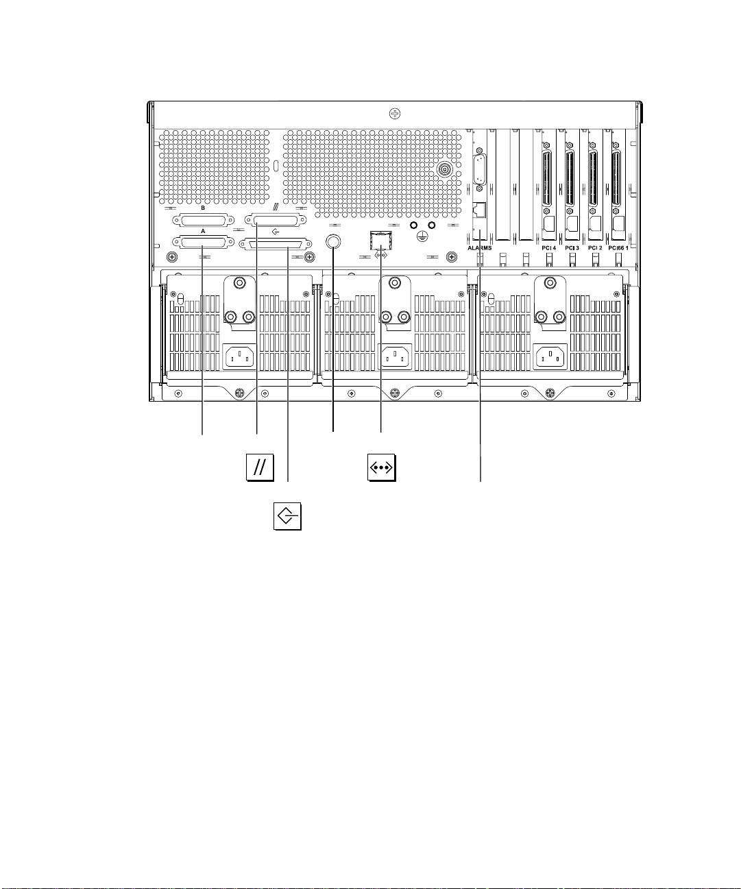
ParallelSerial
Keyboard
A and B
FIGURE 4-1 Back Panel Connectors
TPE
AlarmsSCSI
28 Netra t 1400/1405 Installation and User’s Guide • September 1999

Parallel Interface
113
25 14
FIGURE 4-2 DB-25 Parallel Connector
TABLE4-1 Parallel Connector Pinout
Pin Signal Name I/O Service
1 DATA_STROBE_L Data Strobe (actibe LOW)
2 DAT(0) Data Bit 0
3 DAT(1) Data Bit 1
4 DAT(2) Data Bit 2
5 DAT(3) Data Bit 3
6 DAT(4) Data Bit 4
7 DAT(5) Data Bit 5
8 DAT(6) Data Bit 6
9 DAT(7) Data Bit 7
10 ACK_L Acknowledge (active LOW)
11 BSY Busy (active HIGH)
12 PERROR Paper End (active HIGH)
13 SELECT_L Select (active ???)
14 AFXN_L Auto Line Feed (active LOW)
15 ERROR_L Error (active LOW)
16 RESET_L Initialize Printer (prime active LOW)
17 IN_L Select Input (active LOW)
18 GND Ground
19 GND Ground
20 GND Ground
21 GND Ground
Chapter 4 External I/O Connections 29

TABLE4-1 Parallel Connector Pinout (Continued)
Pin Signal Name I/O Service
22 GND Ground
23 GND Ground
24 GND Ground
25 GND Ground
Serial Connectors
113
25 14
25 14
FIGURE 4-3 DB-25 Serial Connectors
B
113
A
TABLE4-2 Serial Connector Pinout, RS423/RS232
Pin Function I/O Signal Description
1 none none Not connected
2 TxD O Transmit Data
3 RxD I Receive Data
4 RTS O Ready To Send
5 CTS I Clear To Send
6 DSR I Data Set Ready
7 Gnd Signal Ground
8 DCD I Data Carrier Detect
9–14 none none Not connected
15 TRxC I Transmit Clock
16 none none Not connected
17 RTxC I Receive Clock
30 Netra t 1400/1405 Installation and User’s Guide • September 1999

TABLE4-2 Serial Connector Pinout, RS423/RS232 (Continued)
Pin Function I/O Signal Description
18–19 none none Not connected
20 DTR O Data Terminal Ready
21-23 none none Not connected
24 TxC O Transmit Clock
25 none none Not connected
Note: For information about serial port jumpers on the Netra t 1400/1405 system main logic board, see the Netra t 1400/1405 System
Reference Manual.
Twisted-Pair Ethernet (TPE) Connector
81
FIGURE 4-4 RJ45 TPE Socket
TABLE4-3 TPE Connector Pinout
Pin Description Pin Description
1 Transmit Data + 5 Common Mode Termination
2 Transmit Data – 6 Receive Data –
3 Receive Data + 7 Common Mode Termination
4 Common Mode Termination 8 Common Mode Termination
TPE Cable-Type Connectivity
The following types of twisted-pair Ethernet cable can be connected to the
8-pin TPE connector:
■ For 10BASE-T applications, shielded twisted-pair (STP) cable:
■ Category 3 (STP-3, voice grade)
■ Category 4 (STP-4)
■ Category 5 (STP-5, data grade)
■ For 100BASE-T applications, shielded twisted-pair category 5 (STP-5, data grade)
cable.
Chapter 4 External I/O Connections 31

TABLE4-4 TPE STP-5 Cable Lengths
Cable Type Application(s) Max Length
Shielded twisted pair category 5 (STP-5, data
10BASE-T 1000m 3282ft
(Metric)
grade)
Shielded twisted pair category 5 (STP-5, data
100BASE-T 100m 327ft
grade)
SCSI Connector
34
68
FIGURE 4-5 68-Pin SCSI Connector
TABLE4-5 68-Pin SCSI Connector Pinout
Pin Signal Name Pin Signal Name
1 GND 21 GND
2 GND 22 GND
3 GND 23 GND
4 GND 24 GND
5 GND 25 GND
6 GND 26 GND
7 GND 27 GND
8 GND 28 GND
9 GND 29 GND
10 GND 30 GND
11 GND 31 GND
12 GND 32 GND
13 GND 33 GND
14 GND 34 GND
Max Length
(Imperial)
1
35
32 Netra t 1400/1405 Installation and User’s Guide • September 1999

TABLE4-5 68-Pin SCSI Connector Pinout (Continued)
Pin Signal Name Pin Signal Name
15 GND 35 –DB<12>
16 GND 36 –DB<13>
17 TERMPWR 37 –DB<14>
18 TERMPWR 38 –DB<15>
19 Not connected 39 –PAR<1>
20 GND 40 –DB<0>
41 –DB<1> 55 –ATN
42 –DB<2> 56 GND
43 –DB<3> 57 –BSY
44 –DB<4> 58 –ACK
45 –DB<5> 59 –RST
46 –DB<6> 60 –MSG
47 –DB<7> 61 –SEL
48 –PAR<0> 62 –CD
49 GND 63 –REQ
50 TERM.DIS 64 –IO
51 TERMPWR 65 –DB<8>
52 TERMPWR 66 –DB<9>
53 Reserved 67 –DB<10>
54 GND 68 –DB<11>
Note – All signals shown in TABLE 4-5 on page 32 are active low.
SCSI Implementation
■ SCSI-3 Fast-20 (UltraSCSI) parallel interface
■ 16-bit SCSI bus
■ 40Mbps data transfer rate
■ Support for 16 SCSI addresses:
■ Target 0 to 6 and 8 to F for devices
■ Target 7 reserved for SCSI host adapter on main logic board
Chapter 4 External I/O Connections 33

■ Support for up to seven internal SCSI devices (including the host adapter):
■ Fast-20 SCSI disk drive target 0 (left-most drive slot)
■ Fast-20 SCSI disk drive target 1
■ Fast-20 SCSI disk drive target 2
■ Fast-20 SCSI disk drive target 3 (right-most drive slot)
■ Fast-10 SCSI removable media device target 4
■ Fast-10 SCSI removable media device target 6
■ Support for external 8-bit and 16-bit SCSI devices via 68-pin SCSI connector
mounted on an adapter board
SCSI Cabling and Configuration
The SCSI-3 Fast-20 (UltraSCSI) specification requires that the external SCSI bus
length be limited to 3m (10ft) for less than five devices (internal and external), and
1.5m (5ft) for five to eight devices. When SCSI-3 and SCSI-2 devices are connected to
the Netra t 1400/1405 system SCSI bus, the system enables each device to operate at
its respective data transfer rate. The last external SCSI device in a daisy-chain must
be terminated internally (active termination) or with an external terminator
according to Forced-Perfect Termination (FPT) technology.
SCSI Cabling Procedure
1. Count the number of SCSI devices on the system SCSI bus. Be sure to count the
host adapter as a SCSI device.
2. Determine the total SCSI bus length.
TABLE4-6
SCSI Implementation Bus Width
SCSI-2, Fast 8 bits 10 1–8 6.0m
SCSI-2, Fast/Wide 16 bits 20 1–8 6.0m
SCSI-3 Parallel Interface, Fast-20 Wide
(UltraSCSI) (WideUltra)
SCSI-3 Parallel Interface, Fast-20 Wide
(UltraSCSI) (WideUltra)
* The maximum number of single-ended/differentialSCSI devices is 16.
34 Netra t 1400/1405 Installation and User’s Guide • September 1999
Determining SCSI Bus Length
16 bits 40 1–4 3.0m
16 bits 40 5–8
DataTransfer
Rate, Mb/s
Number of
Devices
*
SCSI
Bus Length
1.5m

3. Verify the cable type used to connect external SCSI devices. You must use Fast-20 SCSI cable(s).
Ensure that the total SCSI cable length does not exceed the permissible total SCSI
bus length.
SCSI-2 (Fast Wide SCSI) External Devices
If you connect SCSI-2 (Fast Wide SCSI, 20Mbyte data transfer rate) external devices
to a Netra t 1400/1405 system, follow these cabling and configuration guidelines (as
shown in
■ If all external mass storage devices use 68-pin connectors, connect all non-Sun
devices to the Netra t 1400/1405 system first and follow them with Sun devices.
Sun devices use auto-termination.
■ If external mass storage devices consist of 68-pin Sun devices and 50-pin devices,
connect the Sun 68-pin devices to the Netra t 1400/1405 system first and
terminate the daisy chain with the 50-pin device and its terminator.
■ The total SCSI bus length for all external SCSI devices is 6.0m (19.7ft).
FIGURE 4-6) to ensure proper device addressing and operation:
Non-Sun device
1400
FL SUN 2
Non-Sun device
1400
FIGURE 4-6 Connecting External Mass Storage Devices
Sun device
Sun device
Adaptor cable
Sun device
50-pin device
Terminator
Chapter 4 External I/O Connections 35

Alarms Ports
The alarms service port connector is located on the alarms card. This connector is a
male DB-15 and
TABLE 4-7 lists each connector pin assignment.
9
FIGURE 4-7 DB-15 (Male) Alarms Service Port Connector
TABLE4-7 Alarms Service Port Connector Pinout
Pin Signal Name Pin Signal Name
1 Not connected 9 ALARM1_NC
2 Not connected 10 ALARM1_COM
3 Not connected 11 ALARM2_NO
4 Not connected 12 ALARM2_NC
5 ALARM3_NO 13 ALARM2_COM
6 ALARM3_NC 14 Not connected
7 ALARM3_COM 15 Not connected
8 ALARM1_NO Shell CHGND
18
15
The remote Lights Out Management serial port is located below the alarms port. The
connector is a shielded RJ45 and
TABLE 4-8 lists the connector pin assignments.
36 Netra t 1400/1405 Installation and User’s Guide • September 1999

81
FIGURE 4-8 RJ45 Lights Out Management Serial Connector
TABLE4-8 Lights Out Management Serial Connector Pinout
Pin Signal Name Pin Signal Name
1 RTS 5 REF (0V)
2 DTR 6 RXD
3 TXD 7 DSR
4 REF (0V) 8 CTS
Shell CHGND
Chapter 4 External I/O Connections 37

38 Netra t 1400/1405 Installation and User’s Guide • September 1999

CHAPTER
5
Installing the Alarms Software
This chapter describes the procedure for installing a Netra t 1400/1405 LOMlite
alarms software release. In order to do this you should be familiar with the Solaris
operating environment. Procedures for local and network installation are provided.
The release software consists of a CD-ROM containing the following packages:
SUNWlomm, SUNWlomr, SUNWlomu
SUNWtsvts, SUNWtsvtx
Local Installation
To perform a local installation, your Netra t 1400/1405 must be equipped with a
CD-ROM drive.
▼ Installation Procedure
1. Log on as root.
2. Insert the Lights Out Management release CD-ROM in the drive.
3. Add the packages to the system:
% pkgadd -d /cdrom/cdrom0/Product SUNWlom*
4. Verify that the packages have been installed successfully.
% pkgchk -v SUNWlom[m|r|u]
39

▼ Network Installation Procedure
To perform a network installation, your server must be equipped with a CD-ROM
drive.
▼ Installation Procedure
1. Log on to the server as root.
2. Insert the Lights Out Management release CD-ROM in the drive.
3. Create a directory in /export.
For example:
% mkdir /export/lom_software
Note – The directory /export should be visible to the machines on the network.
4. Copy the contents of the Lights Out Management CD-ROM into the new directory.
For example:
% cp -r /cdrom/cdrom0/* /export/lom_software
5. On the client, mount the lom_software directory on a suitable directory:
% mount -F nfs -o ro <
6. Add the packages to the system:
% pkgadd -d /mnt/Product SUNWlom*
7. Verify that the packages have been installed successfully:
% pkgchk -v SUNWlom[m|r|u]
40 Netra t 1400/1405 Installation and User’s Guide • September 1999
server name
>:/export/lom_software /mnt

SunVTS Software
Note – You must install the SunVTS software, SUNWvts and SUNWvtstk, before
installing the Netra t 1400/1405 vts files. For 64-bit support, you must also install the
SUNWvtsx and SUNWvtstx packages.
▼ Installation Procedure
1. Install the SunVTS software according to the instructions given in the appropriate
SunVTS User’s Guide.
2. Log on as root.
3. Insert the Lights Out Management CD-ROM in the drive.
4. Add the packages to the system:
% pkgadd -d /cdrom/cdrom0/Product SUNWtsvts
5. If 64-bit support is required add the additional packages:
% pkgadd -d /cdrom/cdrom0/Product SUNWtsvtx
6. Verify that the packages have been installed successfully:
% pkgchk -v SUNWtsvt[s|x]
Chapter 5 Installing the Alarms Software 41

42 Netra t 1400/1405 Installation and User’s Guide • September 1999
 Loading...