


Netra™t1
User and Administration Guide
Sun Microsystems, Inc.
901 San Antonio Road
Palo Alto, CA 94303
U.S.A. 650-960-1300
Part No. 806-4707-10
June 2000, Revision A
Send comments about this document to: docfeedback@sun.com

Copyright 2000Sun Microsystems, Inc.,901 SanAntonio Road• PaloAlto, CA94303 USA.All rightsreserved.
This product or documentis protectedby copyrightand distributed under licenses restrictingits use,copying, distribution, and
decompilation. No part ofthis productor documentmay be reproduced inany form by any meanswithout priorwritten authorization
of Sun and itslicensors, ifany.Third-party software,including fonttechnology,is copyrightedand licensedfrom Sunsuppliers.
Parts of the product maybe derivedfrom BerkeleyBSD systems,licensed fromthe University of California. UNIX is a registered trademarkin
the U.S. and other countries, exclusively licensed through X/OpenCompany, Ltd.
Sun, Sun Microsystems,the Sunlogo, AnswerBook2,docs.sun.com, Netraand Solarisare trademarks,registered trademarks, orservice marks
of Sun Microsystems,Inc. inthe U.S.and othercountries. AllSPARCtrademarks areused under license and aretrademarks orregistered
trademarks of SPARC International, Inc. in the U.S. and other countries. Productsbearing SPARCtrademarks arebased uponan architecture
developed by Sun Microsystems, Inc.
The OPEN LOOK and Sun™ Graphical User Interface was developed by SunMicrosystems, Inc.for itsusers andlicensees. Sunacknowledges
the pioneering effortsof Xeroxin researchingand developing the concept of visual orgraphical userinterfaces forthe computerindustry.Sun
holds a non-exclusive license fromXerox tothe XeroxGraphical User Interface, which license also covers Sun’s licensees who implement OPEN
LOOK GUIs and otherwise comply with Sun’s written license agreements.
RESTRICTEDRIGHTS: Use, duplication, or disclosure bythe U.S. Government is subject to restrictions of FAR 52.227-14(g)(2)(6/87) and
FAR52.227-19(6/87), or DFAR252.227-7015(b)(6/95) and DFAR227.7202-3(a).
DOCUMENTATION ISPROVIDED “AS IS” AND ALLEXPRESS OR IMPLIED CONDITIONS, REPRESENTATIONS AND WARRANTIES,
INCLUDING ANY IMPLIED WARRANTY OF MERCHANTABILITY, FITNESS FOR A PARTICULAR PURPOSE OR NONINFRINGEMENT, ARE DISCLAIMED, EXCEPT TO THE EXTENT THAT SUCH DISCLAIMERS ARE HELD TO BE LEGALLY INVALID.
Copyright 2000 Sun Microsystems, Inc.,901 SanAntonio Road• PaloAlto, CA94303 Etats-Unis.Tousdroits réservés.
Ce produit oudocument estprotégé par un copyrightet distribuéavec deslicences quien restreignentl’utilisation,la copie,la distribution,et la
décompilation. Aucune partie de ce produit oudocument nepeut êtrereproduitesous aucuneforme, parquelque moyenque cesoit, sans
l’autorisation préalable et écrite de Sun et de ses bailleurs delicence, s’ily ena. Lelogiciel détenupar destiers, etqui comprendla technologie
relativeaux policesde caractères,est protégépar un copyright et licencié par des fournisseurs de Sun.
Des parties de ce produitpourront êtredérivées des systèmes Berkeley BSD licenciés par l’Université de Californie. UNIX est une marque
déposée aux Etats-Unis et dans d’autrespays etlicenciée exclusivementpar X/OpenCompany, Ltd.
Sun, Sun Microsystems,le logoSun, AnswerBook2,docs.sun.com, Netraet Solarissont desmarques defabrique oudes marquesdéposées, ou
marquesde service,de SunMicrosystems, Inc.aux Etats-Uniset dansd’autres pays. Touteslesmarques SPARCsont utiliséessous licenceet
sontdes marquesde fabriqueou des marques déposées de SPARCInternational, Inc.aux Etats-Uniset dansd’autres pays.Les produitsportant
les marques SPARCsont baséssur unearchitecture développée par Sun Microsystems, Inc.
L’interfaced’utilisation graphique OPEN LOOK et Sun™ a été développéepar SunMicrosystems, Inc.pour sesutilisateurs etlicenciés. Sun
reconnaîtles effortsde pionniersde Xeroxpour la rechercheet ledéveloppement duconcept desinterfaces d’utilisationvisuelle ougraphique
pour l’industrie de l’informatique. Sun détient une licence non exclusive deXerox surl’interface d’utilisationgraphique Xerox,cette licence
couvrant également les licenciés de Sun qui mettenten placel’interface d’utilisationgraphique OPENLOOK etqui enoutre seconforment aux
licences écrites de Sun.
CETTE PUBLICATION EST FOURNIE "EN L’ETAT" ET AUCUNE GARANTIE, EXPRESSE OU IMPLICITE, N’EST ACCORDEE, Y
COMPRIS DES GARANTIES CONCERNANT LA VALEUR MARCHANDE, L’APTITUDE DE LA PUBLICATION A REPONDRE A UNE
UTILISATION PARTICULIERE, OU LE FAIT QU’ELLE NE SOIT PAS CONTREFAISANTE DE PRODUIT DE TIERS. CE DENI DE
GARANTIE NE S’APPLIQUERAIT PAS, DANS LA MESURE OU IL SERAIT TENU JURIDIQUEMENT NUL ET NON AVENU.
Please
Recycle

Contents
Part I. Installation and Configuration
1. Before You Begin 1
The Netra t1 Model 100/105 System 2
The Contents of the Ship Kit 3
Netra t1 Option Modules Available 3
The Tools You Need for Installation 4
Your Operating Environment 4
The System’s Tolerance of Different Environmental Conditions 4
Acoustic Noise Generated by the Netra t1 5
Environmental Compliance Information 5
Choosing Between a Rack and a Cabinet 5
2. Operating Power and Cooling 7
Operating Power Statistics 8
Calculating the Power Requirements for your Netra t1 9
Calculating the Heat To Be Dissipated 10
3. Using DC Power 11
DC Source Site Requirements 12
Overcurrent Protection Requirements 13
iii

DC Connection Materials 14
Grounding 14
DC Supply and Ground Conductor 14
Assembling the DC Input Power Cable 15
▼ To Assemble the DC Input Power Cable 15
▼ To Install the Strain Relief Housings 18
4. Installing Hardware Option Modules 21
Installing or Removing Hot-Pluggable Hard Disk Drives 22
Opening the Netra t1 System 23
Identifying the Parts of the Netra t1 26
Installing a CD-ROM Drive 27
Installing Additional Memory 29
Installing a PCI Card 29
5. Installing the Netra t1 into a Rack 31
Installing into a Sun 72-inch Rack 32
The 72-inch Expansion Rack Mounting Kit 32
▼ To Assemble the Slides and Mount the System 33
▼ To Fit the Cable Management Bracket 37
Installing into a 19-inch Rack 38
The 19-inch Rack Mounting Kit 38
▼ To Assemble the Slides and Mount the System 39
▼ To Fit the Cable Management Bracket 42
Installing into a Two-Post Relay Rack 43
The Fixed Mounting Bracket Kit 43
▼ To Fit the Fixed Mounting Brackets 43
iv Netra t1 User and Administration Guide • June 2000

6. Connecting the Cables 47
Connecting the Cables to the Netra t1 48
Connecting the Power Cord(s) 50
Setting up Serial Connections 52
Cross-overs for Connecting to a Terminal Server 53
Using a DB25 Adapter for Your Serial Link 55
Using a DB9 Adapter for Your Serial Link 56
Settings for the Serial Connections 57
7. Powering Up the Netra t1 59
Powering Up and Configuring for the First Time 60
Configuring via a Terminal Server 60
Configuring from a Terminal or Workstation 60
▼ To Power the System Up for the First Time 61
Using the Power (On/Standby) Switch 63
8. Using Different Versions of Solaris 65
Installing Solaris release 2.6 66
▼ To Install Solaris 2.6 from the CDs 66
▼ To Install Solaris 2.6 from the Network 67
Installing Solaris release 7 or 8 68
The Patches You Need 68
Patch 108620-04: How to Boot from a CD 69
Patch 108673-01: Setting Environment Variables 70
Part II. Maintenance and Management
9. Monitoring and Managing the System 75
What You Can Use the ‘Lights-Out’ Management (LOM) Facility For 76
How the LOM Device Sends its Event Reports 77
Contents v

When the Operating System is Running and the lomlited Daemon is
Installed and Running 77
When the lomlited Daemon is Not Running 77
Capturing LOM Event Reports Passively on the Serial A/LOM Port 78
Stopping the LOM from Sending Reports to the Serial A Port When the
Daemon is not Running 78
Interrogating the LOM and Using it to Power Up or Reset the System 79
Powering the System Up and Down 79
Resetting the System 80
Checking the Current Status of all Components Monitored by the LOM 80
Viewing the LOM Device’s Event Log 81
Shortening the LOM Commands 82
A Listing of the LOM commands 82
Configuring the LOM to Restart the System Automatically After a Lock-up 84
Other Ways of Configuring the LOM 85
Utilites Associated with the LOM Device 86
Changing the First Character of the LOM Escape Sequence 86
The System’s Front and Back Panel LEDs 87
The Fans Monitored by the LOM Device 88
10. Maintaining the System 89
Optional Accessories 90
Re-using the Data in the Host ID Chip 91
Replacing the Lithium Battery 92
Motherboard Jumpers 93
11. Troubleshooting 95
vi Netra t1 User and Administration Guide • June 2000

Part III. Appendices
A. Installing Additional Memory 101
Installing a Second Memory Board 102
Materials and Tools Required 102
▼ To Install a Second Memory Board 103
Installing 4 x 256 Mbyte Memory Boards 107
Materials and Tools Required 107
▼ To Install a Stack of Four Memory Boards 109
B. Installing a PCI Card 117
▼ To Prepare the System for Installation 118
▼ To Install the Card 121
Index 127
Contents vii

viii Netra t1 User and Administration Guide • June 2000

Figures
FIGURE 3-1 Stripping the Insulation From the Wire 15
FIGURE 3-2 Opening the DC Connector Cage Clamp (Lever Method) 16
FIGURE 3-3 Opening the DC Connector Cage Clamp (Screwdriver Method) 17
FIGURE 3-4 Assembling the DC Input Power Cable 17
FIGURE 3-5 Inserting the Bottom Portion of the Strain Relief Housing 18
FIGURE 3-6 Routing the Wires Out of the Strain Relief Housing 19
FIGURE 3-7 Securing the Wires to the Strain Relief Housing 19
FIGURE 3-8 Assembling the Strain Relief Housing 20
FIGURE 4-1 Inserting Hard Disks into the Drive Bays 22
FIGURE 4-2 Using an Anti-Static Wrist Strap 23
FIGURE 4-3 Removing the Rack Mount Brackets 24
FIGURE 4-4 Removing the Top Cover 25
FIGURE 4-5 The Components of the Netra t1 System 26
FIGURE 4-6 Installing an Internal CD-ROM Drive 27
FIGURE 5-1 Cable Management Bracket 32
FIGURE 5-2 Slide Mounts for Sun 72-inch Expansion Rack 33
FIGURE 5-3 Fixing Slide Mounts into a Sun 72-inch Expansion Rack – Rear View (side panels removed
for clarity) 34
FIGURE 5-4 Fixing Slide Mounts into the Sun 72-inchExpansion Rack – Front View (side panels removed
for clarity) 35
ix

FIGURE 5-5 Adjusting the Mount and Tightening the Thumbscrew 36
FIGURE 5-6 The Cable Management Bracket Installed in a Sun 72-inch Expansion Rack 37
FIGURE 5-7 The Cable Management Bracket 38
FIGURE 5-8 19-inch Rack Slide Mounts 39
FIGURE 5-9 Fitting 19-inch Slide Mounts to the Rack 40
FIGURE 5-10 Fitting the Netra t1 into a 19-inch Rack 41
FIGURE 5-11 The Cable Management Bracket Installed in a 19-inch Rack 42
FIGURE 5-12 Removing the Thumbscrew Brackets 43
FIGURE 5-13 Fitting the Fixed Mounting Brackets 44
FIGURE 5-14 The Netra t1 Installed in a Two-Post Rack 45
FIGURE 6-1 Connecting the Netra t1 Model 100 System 48
FIGURE 6-2 Connecting the Netra t1 Model 105 System 48
FIGURE 6-3 Model 100: Connecting a DC Power Cord 50
FIGURE 6-4 Model 105: Connecting the AC Power Cord 50
FIGURE 6-5 Patch Panel Connection Between a Cisco L2511 and a Netra t1 System 53
FIGURE 6-6 Serial Port Pins 1 to 8 54
FIGURE 6-7 Pins 1 to 8 on the Serial Ports 55
FIGURE 6-8 Pins 1 to 8 on the Serial Ports 56
FIGURE 7-1 Model 100 System Switch 63
FIGURE 7-2 Model 105 System Switch 63
FIGURE 9-1 The environment Command Showing Fan 3 and DC Input Supply Faults 80
FIGURE 9-2 Sample LOM Device Event Log (oldest event reported first) 81
FIGURE 9-3 Front Panel Power and Fault LEDs 87
FIGURE 9-4 Back Panel Ethernet Link, Power and Fault LEDs 87
FIGURE 9-5 Locations of Fans 1, 2, and 3 88
FIGURE 10-1 Location of the Host ID Chip on the Motherboard 91
FIGURE 10-2 Motherboard Components (including the Lithium Battery) 92
FIGURE 10-3 Motherboard Jumper Locations 94
x Netra t1 User and Administration Guide • June 2000

FIGURE A-1 The 2-Stackable Memory Board Kit 102
FIGURE A-2 Lifting out the Processor Cover 103
FIGURE A-3 Removing the Mounting Screws from the Currently Installed Memory Board 104
FIGURE A-4 Removing the Old Screws and Inserting the New Ones 105
FIGURE A-5 Seating the Second Memory Board 106
FIGURE A-6 The 4-Stackable Memory Board Kit 108
FIGURE A-7 Lifting out the Processor Cover 109
FIGURE A-8 Removing the Mounting Screws from the Currently Installed Memory Board 110
FIGURE A-9 Seating a Single Memory Board on the Netra t1’s Motherboard 111
FIGURE A-10 Stacking the Third Memory Board on Top of the Second 112
FIGURE A-11 Aligning the Four Plastic Spacers with the Mounting Holes 112
FIGURE A-12 Mounting the Second and Third Boards onto the Base Memory Board 113
FIGURE A-13 Four Stacked Memory Boards on the Netra t1 Motherboard 114
FIGURE A-14 Dropping the Screws into the Aligned Mounting Holes 115
FIGURE B-1 Lifting out the Processor Cover 118
FIGURE B-2 Unclipping the Slide Retainer 119
FIGURE 11-1 Removing the Rear Screw and Pushing the Mid Baffle Towards the Front 119
FIGURE B-3 Lifting Out the Mid Baffle 120
FIGURE B-4 Removing a PCI Card 120
FIGURE B-5 Installing a PCI Card (viewed from the front) 121
FIGURE B-6 Replacing the Mid Baffle 122
FIGURE B-7 Using the Slide Retainer to Hold the Corner of the PCI Card in Place 123
FIGURE B-8 Replacing the Processor Cover 124
FIGURE B-9 Replacing the Lid 125
FIGURE B-10 Re-installing the Rack Mount Brackets 125
Figures xi

xii Netra t1 User and Administration Guide • June 2000

Tables
TABLE 1-1 Contents of the Ship Kit 3
TABLE 2-1 Operating Power Statistics for the Netra t1 Model 100 and Model 105 8
TABLE 2-2 Estimated Power Consumption of the Components of the Netra t1 9
TABLE 3-1 Overcurrent Protection Requirements 13
TABLE 5-1 72-inch Expansion Rack Mounting Kit 32
TABLE 5-2 19-inch Rack Mounting Kit 38
TABLE 5-3 Fixed Bracket Mounting Kit 43
TABLE 6-1 Pin Cross-overs for Connecting to a Typical Terminal Server 54
TABLE 6-2 Pin Cross-overs in the Sun DB25 (25-pin) Adapter 55
TABLE 6-3 Pin Cross-overs for a DB9 (9-pin) Adapter 56
TABLE 6-4 Settings for Connecting to the Serial A/LOM or Serial B Port 57
TABLE 8-1 Patches Required for Solaris 2.6 (5/98), or Solaris 7 or 8 69
TABLE 9-1 LOM Commands 82
TABLE 9-2 LOM Configuration File Parameters 85
TABLE 10-1 Orderable Options 90
TABLE 10-2 Jumper Settings 93
xiii

xiv Netra t1 User and Administration Guide • June 2000

Preface
This manual tells you how to install, maintain and manage a Netra t1 Model
100/105 server.
How This Book Is Organized
Part I “Installation and Configuration”
Chapter 1 “Before You Begin”
Introduces the Netra t1 Model 100/105 server and tells you what tools to use to
install the system. It also describes the equipment’s tolerance of different
environmental conditions.
Chapter 2 “Operating Power and Cooling”
Provides information about the power and cooling requirements for the Netra t1.
Chapter 3 “Using DC Power”
Tells you the site requirements for using DC power, and also tells you how to
assemble the DC input power cable.
Chapter 4 “Installing Hardware Option Modules”
Tells you how to install optional (hot-pluggable) hard disk drives. The chapter also
tells you how to open the Netra t1, how to identify its component parts, and how to
install a CD-ROM drive.
Chapter 5 “Installing the Netra t1 into a Rack”
Tells you how to install the Netra t1 into different types of rack.
Chapter 6 “Connecting the Cables”
Tells you how to cable up and set up serial connections to the Netra t1.
xv

Chapter 7 “Powering Up the Netra t1”
Tells you how to perform the initial power up and configuration of the Netra t1.
Chapter 8 “Using Different Versions of Solaris”
Tells you how to install different versions of Solaris.
Part II “Maintenance and Management”
Chapter 9 “Monitoring and Managing the System”
Tells you how to use the ‘Lights-Out’ Management (LOM) facility to power the
system on and off or reset it remotely and how to inspect status information about
the system’s fans and power supply. The chapter also tells you how to configure the
LOM facility to restart the system automatically in the event of a lock-up.
Chapter 10 “Maintaining the System”
Lists the Field Replaceable Units and optional accessories that you might want to
order for the Netra t1 during its life-time. If you ever need to replace an entire Netra
t1 system, the chapter also tells you how to retain the configuration information for
one system so that it can be transferred to another.
Chapter 11 “Troubleshooting”
Lists some problems that you might encounter setting up or using the Netra t1
system and tells you how to solve them.
Part III “Appendices”
Appendix A “Installing Additional Memory”
Tells you how to install more memory into the Netra t1.
Appendix B “Installing a PCI Card”
Tells you now to install a PCI card into the Netra t1.
Using UNIX Commands
This document does not contain information on basic UNIX®commands and
procedures such as shutting down the system, booting the system, and configuring
devices.
See one or more of the following for this information:
■ AnswerBook™ online documentation for the Solaris™ software environment
■ Other software documentation that you received with your system
xvi Netra t1 User and Administration Guide • June 2000

Typographic Conventions
Typeface Meaning Examples
AaBbCc123 The names of commands, files,
and directories; on-screen
computer output
Edit your .login file.
Use ls -a to list all files.
% You have mail.
AaBbCc123 What you type, when
contrasted with on-screen
computer output
AaBbCc123 Book titles, new words or
terms, words to be emphasized
Command-line variable;
replace with a real name or
value
% su
Password:
Read Chapter 6 in the User’s Guide.
These are called class options.
You must be superuser to do this.
To delete a file, type rm filename.
Shell Prompts
Shell Prompt
C shell machine_name%
C shell superuser machine_name#
Bourne shell and Korn shell $
Bourne shell and Korn shell superuser #
LOM shell lom>
Preface xvii
Sun Welcomes Your Comments
We are interested in improving our documentation and welcome your comments
and suggestions. You can email your comments to us at:
docfeedback@sun.com
Please include the part number of your document in the subject line of your email.
Safety Precautions
For your protection, observe the following safety precautions when setting up your
equipment:
■ Follow all cautions and instructions marked on the equipment.
■ Never push objects of any kind through openings in the equipment. Dangerous
voltages may be present. Conductive foreign objects can produce a short circuit
that could cause fire, electric shock, or damage to your equipment.
Symbols
The following symbols may appear in this manual:
Caution – There is a risk of personal injury and equipment damage. Follow the
instructions.
Caution – Hazardous voltages are present. To reduce the risk of electric shock and
danger to personal health, follow the instructions.
xviii Netra t1 User and Administration Guide • June 2000

Modifications to Equipment
Do not make mechanical or electrical modifications to the equipment. Sun
Microsystems is not responsible for the regulatory compliance of a modified
product.
Caution – Do not block or cover the openings of your Sun product. Never place a
Sun product near a radiator or heat register. Failure to follow these guidelines can
cause overheating and affect the reliability of your Sun product.
Caution – If your Netra t1 system is installed in a closed or multi-unit rack
assembly, the operating ambient temperature of the rack environment may exceed
the room ambient temperature. Ensure that rack environment ambient temperature
does not exceed 40 degrees. The system will tolerate ambient temperatures of up to
55 degrees, but these temperatures must not persist for more than 96 hours.
Caution – Mounting of the equipment in a rack or cabinet should be such that a
hazardous condition is not created due to uneven mechanical loading or weight
distribution.
Caution – Ensure that the connection of multiple system units to the circuit does
not overload the the supply overcurrent protection or supply wiring. Consider the
Sun agency label electrical ratings when determining the correct branch circuit
rating for your installation.
Caution – All supply connections, wiring, wire protection, and wire routing must
be made in accordance with applicable sections and requirements of national
electrical code and local electrical authorities.
Preface xix

xx Netra t1 User and Administration Guide • June 2000

PART
I Installation and Configuration


CHAPTER
1
Before You Begin
This chapter contains the following sections:
■ “The Netra t1 Model 100/105 System” on page 2
■ “The Contents of the Ship Kit” on page 3
■ “Netra t1 Option Modules Available” on page 3
■ “The Tools You Need for Installation” on page 4
■ “Your Operating Environment” on page 4
■ “Choosing Between a Rack and a Cabinet” on page 5
What’s Next?
When you have read this chapter introducing the Netra t1, go to Chapter 2 to find
out how to calculate the power and cooling requirements for your system.
1

The Netra t1 Model 100/105 System
The Netra t1 Model 100/105 computer system is a single-processor server designed
primarily for use by telecommunications carriers and internet service providers.
The Model 100 is powered by –48VDC/–60VDC supplies. The Model 105 is
powered by an AC supply. This is the only difference between the two models.
The Netra t1 has the following features:
■ Rack-mounting enclosure with single –48VDC/–60VDC (Netra t1 Model 100) or
AC (Netra t1 Model 105) power supply
■ Support for UltraSPARCIIi 360 MHz processor with 1Mbyte cache or
UltraSPARCIIi 440 MHz processor with 2 Mbyte cache
■ Sockets accepting 64, 256 and 512 Mbyte memory cards in single-board, 2-stack,
or 4-stack configurations (giving a maximum of 1 Gbyte of memory)
■ One short (176 mm) 33 MHz, 32 bit, 5VDC PCI card slot
■ Two 10/100 Mbps RJ-45 Ethernet ports
■ Console/Lights Out Management RJ-45 serial port
■ Second RJ-45 serial port
■ Support for up to two low-profile, 3.5 inch Fast-20 (UltraSCSI) disks
■ Low-profile ATAPI CD-ROM drive (this is an orderable hardware option, part
number: 595-5317-01)
■ External Fast-20 (UltraSCSI) 68-pin port
The Netra t1 is designed for rack mounting. Its components are housed in a casing
with the following dimensions:
■ Height: 44 mm (1.73 inches)
■ Width: 440 mm (17.3 inches)
■ Depth: 488.95 mm (19.25 inches)
■ Weight (when all option modules are installed): 10 kg (22 lb)
2 Netra t1 User and Administration Guide • June 2000

The Contents of the Ship Kit
TABLE1-1 Contents of the Ship Kit
Part Number Item Quantity
340-5819-02 19-inch rack mounting brackets 4
340-6151-01 Cable management bracket 1
540-4362-01 Sun slide rail 2
530-2093-01 RJ45-RJ45 patch cable for Ethernet or serial connection 2
530-2889-02 RJ45-DB25 adapter 1
565-1644-01 DC connector kit 1
565-1645-01 10-32 UNF Sun rack mounting screw kit 1
704-6914-10 Solaris Operating Environment Installation CD (9/99 or later) 1
704-7081-10 Bonus CD 1
704-7088-10 iPlanet Web CD 1
806-3947-10 iPlanet manual 1
806-4707-10 Netra t1 System User and Administration Guide 1
806-2274-15 Release Notes 1
Netra t1 Option Modules Available
Sun offer a range of hard disk drives, PCI network interface cards, CD-ROM drives,
and memory cards for the Netra t1 Model 100/105. For a full list of the option
modules available, see Chapter 10.
Chapter 1 Before You Begin 3

The Tools You Need for Installation
■ An 8mm wrench (for assembling the rack mounting)
■ A small flat-head screwdriver (for installing hard disks)
■ An ESD pad and an anti-static wrist strap and earthing point (to protect the
components of the system if you need to install any hardware options)
■ A No 2 Phillips screwdriver (and a No. 1 Phillips screwdriver if you are installing
additional memory)
■ A Thomas & Betts two-hole lug (part number: 54204-UB) and a Thomas & Betts
crimping tool (part number: TBM 5-S) (you will need these tools if you need to
use a two-hole ground connection; see Chapter 3)
Your Operating Environment
The System’s Tolerance of Different Environmental Conditions
You can operate and store the system safely in the following conditions:
■ Ambient temperature
■ Operating: 0˚C to 40˚C (temporary operation outside these limits is permitted
for a maximum of 96 hours within the range –5˚C to 55˚C)
■ Storage: –40˚C to 70˚C
■ Temperature variation
■ Operating: 30˚C/hr maximum
■ Storage: 30˚C/hr maximum
■ Relative humidity
■ Operating: 5% to 85% (non-condensing)
■ Storage: 10% to 95% (non-condensing)
■ Altitude
■ Operating: –300m to +3000m
■ Storage: –300m to +12000m
■ Earthquake
The system conforms to the NEBS requirements for earthquake zone 4
4 Netra t1 User and Administration Guide • June 2000

Acoustic Noise Generated by the Netra t1
The system generates less than 60dBA at a distance of 600mm and a height of
1500mm (operating in an ambient temperature of 25˚C).
Environmental Compliance Information
■ NEBS environmental criteria
The system conforms to GR-63-CORE issue 1, October 1995
■ Electro-magnetic compatibility
■ Immunity: The system conforms to GR-1089-CORE and EN50082-1
■ Emissions: The system conforms to GR-1089-CORE, EN55022 Class A and FCC
Class A
■ Safety
The system conforms to UL 1950 (3rd edition), EN60950, GR-1089-CORE
Choosing Between a Rack and a Cabinet
Netra t1 servers can be installed in either racks or cabinets. Factors that may
influence your decision include:
■ Security
If other people have access to the room in which your Netra systems are located,
you can increase security by locking the systems in a cabinet.
■ Thermal issues
Cabinets often require additional fans, because the systems you install in them are
generating heat in an enclosed space. Two-post racks, however, may require no
special cooling systems.
■ Flooring
Two-post telco relay racks are designed so that cables can be run overhead.
Cabinets often require cables to be run under the floor.
What’s Next?
When you have read this chapter, go to Chapter 2 to find out how to calculate the
power and cooling requirements for your system.
Chapter 1 Before You Begin 5

6 Netra t1 User and Administration Guide • June 2000

CHAPTER
2
Operating Power and Cooling
The chapter contains the following sections:
■ “Operating Power Statistics” on page 8
■ “Calculating the Power Requirements for your Netra t1” on page 9
■ “Calculating the Heat To Be Dissipated” on page 10
What’s Next?
When you have used this chapter to calculate the power and cooling requirements
for your Netra t1 system, go to Chapter 3 which tells you how to assemble the DC
input power cables for the Netra t1 Model 100, or, if you are installing a Model 105
system, go straight to Chapter 4 to find out how to install the optional hardware
modules available for the Netra t1.
7

Operating Power Statistics
TABLE2-1 Operating Power Statistics for the Netra t1 Model 100 and Model 105
Description Netra t1 Model 100 (DC power) Netra t1 Model 105 (AC power)
Maximum Operating
Current
4A @ (–40VDC) 2A @ 90 VAC
Typical Operating
Current
Maximum In-rush
Current
Operating Input
Voltage Range
Voltage Frequency
Range
Power Factor Not Applicable 0.9 to 0.99
Maximum
Volt-Ampere Rating
BTU rating 368 BTU
See “Calculating the Power
Requirements for your Netra
t1” on page 9
20A peak (upon a hot
or cold start
*
)
–40 to –75 VDC 90-264 V
DC 47-63 Hz
120 VA 120 VA
**
See “Calculating the Power
Requirements for your Netra
t1” on page 9
100A peak (upon a cold start
rms
368 BTU
**
*
)
* For both models, the in-rush current decays to the normal operating current in less than
200 msecs. For the AC model, the in-rush current of 100 A lasts for 2 msecs during a cold start
or during a warm start performed 60 seconds (or longer) after the AC was removed.
** This BTU assumes a system fully loaded with hardware option modules.
Caution – The power supply on the Model 105 continues to regulate all outputs for
at least 20 msecs after AC power is removed. On the Model 100, the power supply
continues to regulate all outputs for at least 5 msecs after DC power is removed.
Note – Logic ground and chassis ground are connected together internally within
the system.
Note – Power from the standby output is available whenever input power is
connected.
8 Netra t1 User and Administration Guide • June 2000

Calculating the Power Requirements for your Netra t1
A Netra t1 system containing two disk drives has an estimated power requirement
of approximately 1amp.
TABLE 2-2 shows the estimated power consumed by the individual components in a
fully powered system (that is, in a system with a Power Supply Unit (PSU) operating
at 100% efficiency). However, when you are calculating the power requirements for
your system, you must allow for 65% PSU efficiency. To perform this calculation,
add the figures (from the third column of
the system. Then divide the result by 0.65. Below are two examples.
TABLE2-2 Estimated Power Consumption of the Components of the Netra t1
Component Estimated Power Consumption (at 100% PSU efficiency)
Base system 360MHz 34.3 W
440MHz 36.3 W
Memory (per DIMM) 0.21 W per 64 Mbyte
Disk drive 9 Gbyte/7200 rpm 11.0 W
18Gbyte/10000 rpm 13.8 W
CD-ROM 3.2 W
PCI card Variable (max 25 W)
TABLE 2-2) for each component installed in
Example A
The power requirement for a Netra t1 system operating at 65% PSU efficiency and
containing:
■ the 440 MHz CPU
■ 512Mbyte RAM
■ two 9Gbyte disk drives
is calculated as follows:
36.3 0.21 8×()11.0 2×()++
------------------------------------------------------------------------
0.65
92.28W=
Chapter 2 Operating Power and Cooling 9

Example B
The power requirement for a Netra t1 system operating at 65% PSU efficiency and
containing:
■ 440 MHz CPU
■ 1Gbyte RAM
■ Two 18 Gbyte disk drives
■ CD-ROM drive
is calculated as follows:
36.3 0.21 16×()13.8 2×()3.2+++
-----------------------------------------------------------------------------------------
0.65
108.4W=
Note – To calculate the total power requirement for several Netra t1 systems
installed in a single rack or cabinet, add together the individual power requirement
figure (TABLE 2-2) for each Netra t1 you have installed.
Calculating the Heat To Be Dissipated
To calculate the heat generated by a Netra t1 system so that you can estimate the
heat your cooling system must dissipate, convert the figure for the system’s power
requirement (see “Calculating the Power Requirements for your Netra t1” on page 9)
from watts to BTU/hr. A general formula for doing this is to multiply the figure for
the power requirement by 3.415. For example, the heat that must be dissipated for
the system in:
■ Example A is 92.28 x 3.415=315.14 BTU/hr
■ Example B is 108.4 x 3.415=370.19 BTU/hr
What’s Next?
When you have used this chapter to calculate the power and cooling requirements
for your Netra t1 system, go to Chapter 3 which tells you how to assemble the DC
input power cables for the Netra t1 Model 100, or, if you are installing a Model 105
system, go straight to Chapter 4 to find out how to install the optional hardware
modules available for the Netra t1.
10 Netra t1 User and Administration Guide • June 2000

CHAPTER
3
Using DC Power
This chapter applies only to the Netra t1 Model 100. If you have purchased a
Netra t1 Model 105, skip this chapter and go to Chapter 4 on installing the optional
hardware modules available for the Netra t1.
This chapter contains the following sections:
■ “DC Source Site Requirements” on page 12
■ “DC Connection Materials” on page 14
■ “Assembling the DC Input Power Cable” on page 15
What’s Next?
When you have followed the instructions in this chapter to assemble the DC input
power cables, go to Chapter 4 for information about installing any optional
hardware modules you need. Do not power up the system (see Chapter 7) until you
have installed the Netra t1 into a rack (see Chapter 5), connected up the cables and
set up serial connections to the system (see Chapter 6).
11

DC Source Site Requirements
The Netra t1 Model 100 has a pair of 3-position Wago connectors.
The product is suitable for use in –48 VDC (classified SELV) nominal or –60 VDC
nominal systems.
The DC source must be:
■ Electrically isolated by double or reinforced insulation from any hazardous AC or
DC source
■ Reliably connected to earth
■ Capable of providing up to 150 W of continuous power per feed pair.
Note – The Netra t1 Model 100 must be installed in a restricted access location. As
defined by the National Electrical Code, this is an area intended for qualified or
trained personnel only, access to which is controlled by a locking mechanism (for
example, a key lock or an access card system).
12 Netra t1 User and Administration Guide • June 2000

Overcurrent Protection Requirements
■ Overcurrent protection devices must be provided as part of each host equipment
rack.
■ The supply source must be electrically isolated from any AC source or other
voltages by double or reinforced insulation.
■ Circuit breakers meeting the requirements shown in TABLE 3-1 must be fitted
between the DC source and the Netra t1, and they must be ON when in the UP
position.
TABLE3-1 Overcurrent Protection Requirements
Description
Current rating 7.5A maximum
Voltage Maximum 60 VDC rated in –48 VDC power systems
Type Fast trip
Protection EITHER:
Contact gap Minimum 3 mm
Nuisance tripping Circuit breaker must not operate when presented with an in-rush
Quantity One per feed, up to 2 per system
Requirement
Maximum 75 VDC rated in –60 VDC power systems
Double pole breaking (both grounded and ungrounded conductor
to open on fault)
OR:
Single pole breaking ungrounded conductor (–48V) to open on
fault.
current of 27 amps and a duration of 2.5 microseconds
Note – Overcurrent devices must meet applicable national and local electrical safety
codes and be approved for the intended application.
Chapter 3 Using DC Power 13

DC Connection Materials
Grounding
■ One Thomas & Betts two-hole lug (part number: 54204-UB) suitable for 8 AWG
conductor or UL/CSA approved equivalent having 5/8 inch pitch. Torque value:
3.5Nm maximum. Two M5 studs and cupwasher nuts are supplied on the rear of
the chassis for connection.
■ A Thomas & Betts crimping tool (part number: TBM 5-S), or approved equivalent,
is required to secure the lug onto the cable.
■ An earthing bus bar that is near the equipment and easily accessible.
Caution – External filtering and/or surge suppression devices may be required on
the power feeds where branch circuit electromagnetic characteristics are unknown.
DC Supply and Ground Conductor
The requirements are:
■ Suitable conductor material: tinned copper (stranded) only
■ Conductors: 12AWG maximum (between the Netra t1 Model 100 and the circuit
breaker). There are three conductors:
■ –48VDC/–60VDC Supply (pin 1) (12 AWG)
■ Ground connection to power supply (pin 2) (12 AWG)
■ –48VDC/–60VDC Return (pin 3) (12 AWG)
■ Cable insulation rating: minimum 75˚C, low smoke fume (LSF), flame retardant
■ Cable must conform to GR63-CORE fire resistance requirements
■ Branch circuit cable insulation color: per applicable National Electrical Codes
■ Grounding cable insulation color: green/yellow
14 Netra t1 User and Administration Guide • June 2000
Assembling the DC Input Power Cable
▼ To Assemble the DC Input Power Cable
1. Determine how many DC input power cables you will need from each DC power
source.
2.Turn off power to the DC power source through the circuit breakers.
Caution – Do not proceed with these instructions until you have turned off the
power to the DC power source through the circuit breakers.
3. Take a DC connector from the ship kit.
4. Locate the three wires coming from the DC power source that will be used in the
connection to your unit:
■ –48V Supply
■ Chassis ground
■ –48V Return
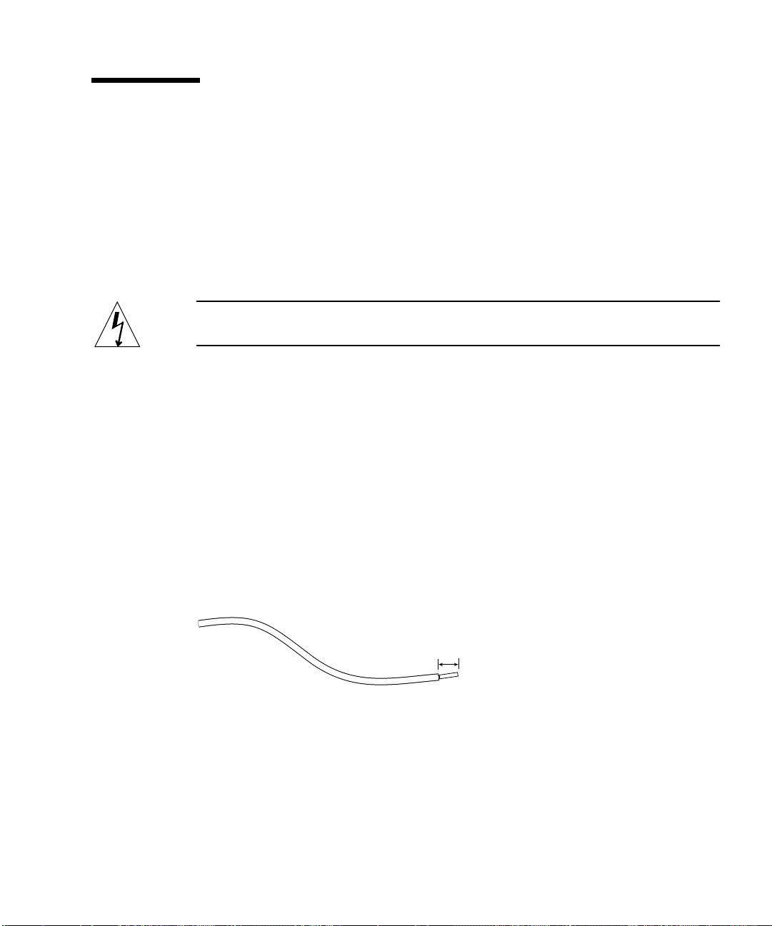
5. Strip 8mm (0.31 inches) of insulation from each of the wires coming from the DC
power source (see
Do not strip more than 8mm (0.31 inches) from each wire. Doing so will leave
uninsulated wire exposed from the DC connector after the assembly is complete.
FIGURE 3-1).
8 mm (0.31 in.)
FIGURE 3-1 Stripping the Insulation From the Wire
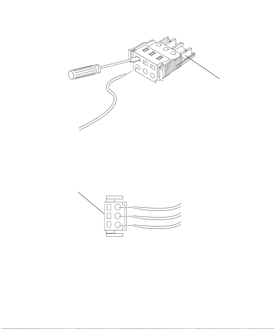
6. Insert the tip of the cage clamp operating lever into the rectangular hole directly
above the hole in the DC connector where you want to insert the first wire and
press down on the cage clamp operating lever (see
FIGURE 3-2).
This opens the cage clamp for this section of the DC connector.
Chapter 3 Using DC Power 15

Top of connector
FIGURE 3-2 Opening the DC Connector Cage Clamp (Lever Method)
You can also open the DC connector cage clamp by inserting a small slotted
screwdriver into the rectangular hole directly above the hole in the DC connector
where you want to insert the first wire, and pressing down on the screwdriver (see
FIGURE 3-3).
16 Netra t1 User and Administration Guide • June 2000
Top of connector
FIGURE 3-3 Opening the DC Connector Cage Clamp (Screwdriver Method)
7. Feed the exposed section of the appropriate wire into that hole in the DC
connector.
FIGURE 3-4 shows which wires should be inserted into each hole in the DC connector.
Top of connector
–48V Return
Ground
123
FIGURE 3-4 Assembling the DC Input Power Cable
–48V
8. Repeat Step 6 and Step 7 for the other two wires to complete the assembly of the
DC input power cable.
9. Repeat Step 4 through Step 8 to create as many DC input power cables as you
need.
If you need to remove a wire from the DC connector, insert the cage clamp operating
lever or a small screwdriver into the slot directly above the wire and press down
(
FIGURE 3-2 and FIGURE 3-3).
Chapter 3 Using DC Power 17
▼ To Install the Strain Relief Housings
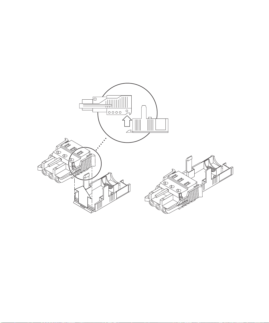
1. Take the DC connector and insert the bottom portion of the strain relief housing
into the notch on the DC connector until it snaps into place (see
Make sure the strain relief housing snaps into place on the DC connector; you will
not be able to complete the assembly correctly if the strain relief housing is not
snapped into place.
FIGURE 3-5).
FIGURE 3-5 Inserting the Bottom Portion of the Strain Relief Housing
2. Route the three wires coming from the DC power source through the opening at
the end of the bottom portion of the strain relief housing (see
18 Netra t1 User and Administration Guide • June 2000
FIGURE 3-6).
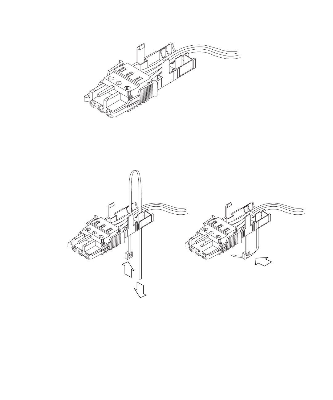
FIGURE 3-6 Routing the Wires Out of the Strain Relief Housing
3. Get the tie wrap and insert it into the bottom portion of the strain relief housing
(see
FIGURE 3-7).
FIGURE 3-7 Securing the Wires to the Strain Relief Housing
4. Loop the tie wrap over the wires and back out of the strain relief housing and
tighten the tie wrap to secure the wires to the strain relief housing (see
Chapter 3 Using DC Power 19
FIGURE 3-7).

5. Lower the top portion of the strain relief housing so that the three prongs on the
top portion insert into the openings in the DC connector, and push the top and
bottom portions of the strain relief housing together until they snap into place
(see
FIGURE 3-8).
FIGURE 3-8 Assembling the Strain Relief Housing
What’s Next?
The DC input power cables for your unit are now completely assembled. For
information about connecting the power cords and other cables, see Chapter 6. Do
not power up the system (see Chapter 7) until you have installed any optional
hardware modules you need (see Chapter 4) and installed the system securely into a
rack or cabinet (see Chapter 5).
20 Netra t1 User and Administration Guide • June 2000

CHAPTER
4
Installing Hardware Option Modules
If you do not want to install any hardware option modules, skip this chapter and go
straight to Chapter 5 which tells you how to install the Netra t1 system into a rack.
This chapter tells you how to install or remove the hot-pluggable hard disk drives
available for the Netra t1. To do this, you do not need to power down the system or
remove it from the rack.
The chapter also tells you how to remove the cover of the Netra t1, how to identify
the parts of the system, and how to install a CD-ROM drive.
For the sales part numbers of the Netra t1 hardware option modules available from
your Sun Enterprise Services representative, see Chapter 10.
The chapter contains the following sections:
■ “Installing or Removing Hot-Pluggable Hard Disk Drives” on page 22
■ “Opening the Netra t1 System” on page 23
■ “Identifying the Parts of the Netra t1” on page 26
■ “Installing a CD-ROM Drive” on page 27
■ “Installing Additional Memory” on page 29
■ “Installing a PCI Card” on page 29
What’s Next?
When you have used this chapter to install the optional hardware modules you
need, go to Chapter 5 for information about installing the Netra t1 into a rack.
21

Installing or Removing Hot-Pluggable Hard Disk Drives
The hard disk drives are hot-pluggable modules. You do not need to power down
the system or remove it from the rack to install or remove hard disk drives.
1. Remove the front bezel by pressing the latch at either end.
Drive 0
3
Drive 1
1
FIGURE 4-1 Inserting Hard Disks into the Drive Bays
2. Lever out the grilles.
3. If you are:
■ Installing hard disk drives, slide the disk drive(s) into their trays in the front of
the system (see
backplane connector.
■ Removing hard disk drives, lift the ejector latch (see FIGURE 4-1) at the front of
each disk drive you are removing and pull the drive out.
4. Replace the grilles and front bezel.
22 Netra t1 User and Administration Guide • June 2000
FIGURE 4-1). Press them firmly to ensure they are engaged with the
2

Note – The Netra t1’s hard disk drives use SCSI IDs 0 and 1. If you are using an
external SCSI device, make sure it does not use these SCSI IDs.
Opening the Netra t1 System
Caution – The system contains electronic parts that are extremely sensitive to static
electricity. Do not touch any metal parts. Wear an anti-static wrist strap connected to
an earthing point before you open the system.
The anti-static
wrist strap must be
connected to an
earthing point
FIGURE 4-2 Using an Anti-Static Wrist Strap
Caution – Before attempting to remove the cover, make sure that all power cords
and all other cables have been disconnected from the system.
1
Chapter 4 Installing Hardware Option Modules 23

1. If your system is new and you have just removed it from its packaging, go straight
to Step 3.
If your system is currently in use, but you need to open it to install an option
module or replace a component, then:
a. Shut down Solaris from the console.
b. Turn the power supply switch off.
c. Disconnect the power cord(s).
d. Disconnect all other cables.
2. If you have installed the system into a rack or cabinet, remove it.
3. Remove the rack mount brackets from the side of the system (see
FIGURE 4-3 Removing the Rack Mount Brackets
4. Place the unit at an ESD station and use an anti-static wrist strap.
5. Remove the system’s top cover (see
FIGURE 4-4).
a. Remove the screw at the rear center of the unit.
b. Slide the top cover back and lift it off.
FIGURE 4-3).
24 Netra t1 User and Administration Guide • June 2000

5a
1
3
2
FIGURE 4-4 Removing the Top Cover
5b
2
Chapter 4 Installing Hardware Option Modules 25
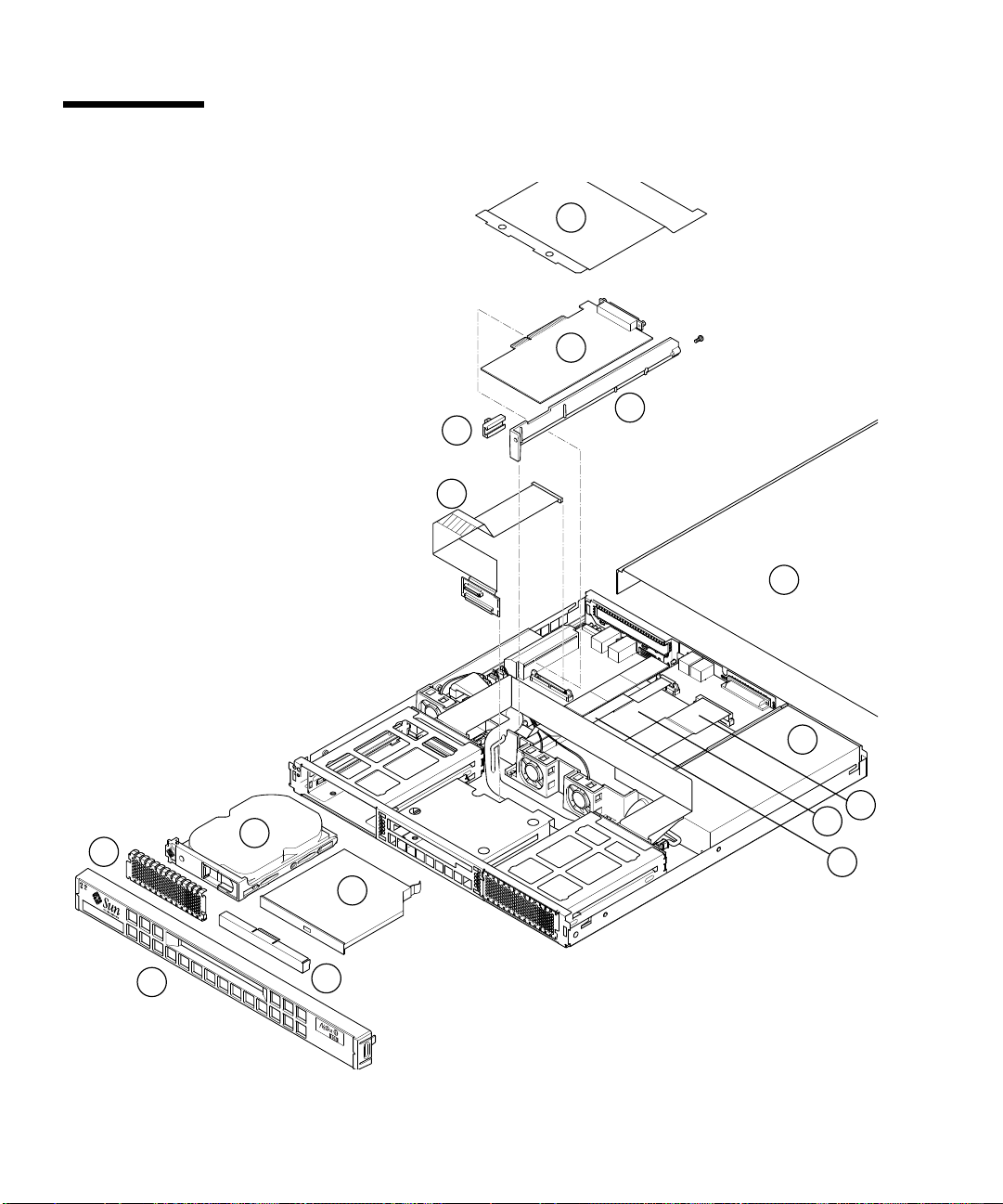
Identifying the Parts of the Netra t1
Key to FIGURE 4-1:
1. Processor cover
2. PCI card
3. Mid baffle
4. CD-ROM drive board and cable
5. Cover
6. Hard disk drive
7. CD-ROM drive (replaces 8)
8. Blanking plate (replaces 7)
9. Front bezel
10. Grille
11. Power supply
12. Internal SCSI cable
13. Motherboard
14. Internal serial cable
15. PCI card slide
retainer
1
2
3
15
4
5
11
6
10
7
9
FIGURE 4-5 The Components of the Netra t1 System
26 Netra t1 User and Administration Guide • June 2000
8
12
13
14

Installing a CD-ROM Drive
Class 1 Laser Product
Luokan 1 Laserlaite
Klasse 1 Laser Apparat
Laser Klasse 1
Caution – Follow the instructions in this section carefully. Do not attempt to install
a CD-ROM drive using any procedure other than the one contained in this section. If
you do, you risk exposure to radiation.
5
4
5
6
2
1
FIGURE 4-6 Installing an Internal CD-ROM Drive
7
Chapter 4 Installing Hardware Option Modules 27

Note – If you are going to install a PCI card, install the CD-ROM drive first. If you
have a PCI card already installed, you will need to remove it before installing the
!
CD-ROM drive (see Appendix B).
1. Remove the top cover by following the procedure described in “Opening the
Netra t1 System” on page 23.
2. Remove the front bezel by pressing the latch at each end (see
3. Remove any PCI card installed in the system (see Appendix B).
4. Squeeze and pull out the blanking panel.
5. Slide the connector card into the slot behind the CD-ROM drive bay (see
FIGURE 4-6).
6. Connect the cable to the slot under the PCI card (see
7. Slide the CD-ROM drive into its bay until the catch clicks (see
8. Re-install the PCI card (if necessary) as described in “To Install the Card” on
page 121 (in Appendix B).
9. Replace the system cover and screws.
10. Replace the front bezel.
FIGURE 4-6).
FIGURE 4-6).
FIGURE 4-6).
28 Netra t1 User and Administration Guide • June 2000

Installing Additional Memory
There are two ways of adding memory to the Netra t1. You can install:
■ A 64, 256, or 512 Mbyte memory board on top of the currently installed board.
■ A stack of four 256 Mbyte memory boards (these must each be of part number
370-4155).
For the sales part numbers of the different 64, 256 and 512 Mbyte memory boards
available from your Sun Enterprise Services representative, see Chapter 10.
To install new memory boards, follow the instructions in Appendix A.
Installing a PCI Card
For a list of the Ethernet, Fast Ethernet, and ATM PCI cards available from your Sun
Enterprise Services representative, see Chapter 10.
To install a PCI card into the Netra t1, follow the instructions in Appendix B.
What’s Next?
When you have installed the optional hardware modules you need, go to Chapter 5
for information about installing the Netra t1 into a rack.
Chapter 4 Installing Hardware Option Modules 29

30 Netra t1 User and Administration Guide • June 2000

CHAPTER
5
Installing the Netra t1 into a Rack
This chapter describes how to mount a Netra t1 system in a rack.
The chapter contains the following sections:
■ “Installing into a Sun 72-inch Rack” on page 32
■ “Installing into a 19-inch Rack” on page 38
■ “Installing into a Two-Post Relay Rack” on page 43
What’s Next?
When you have installed the Netra t1 system into the rack, go to Chapter 6 for
information about connecting up the cables and setting up serial connections.
31
Installing into a Sun 72-inch Rack
The 72-inch Expansion Rack Mounting Kit
The mounting slides can each be used on either side of the rack. The parts required
are listed below:
TABLE5-1 72-inch Expansion Rack Mounting Kit
Description Quantity Part No.
Front slide 2 340-6215
Rear slide 2 340-6234
Cable management bracket 1 340-6151
M4 nuts 4 240-1373
Rack Screw Kit 1 565-1645
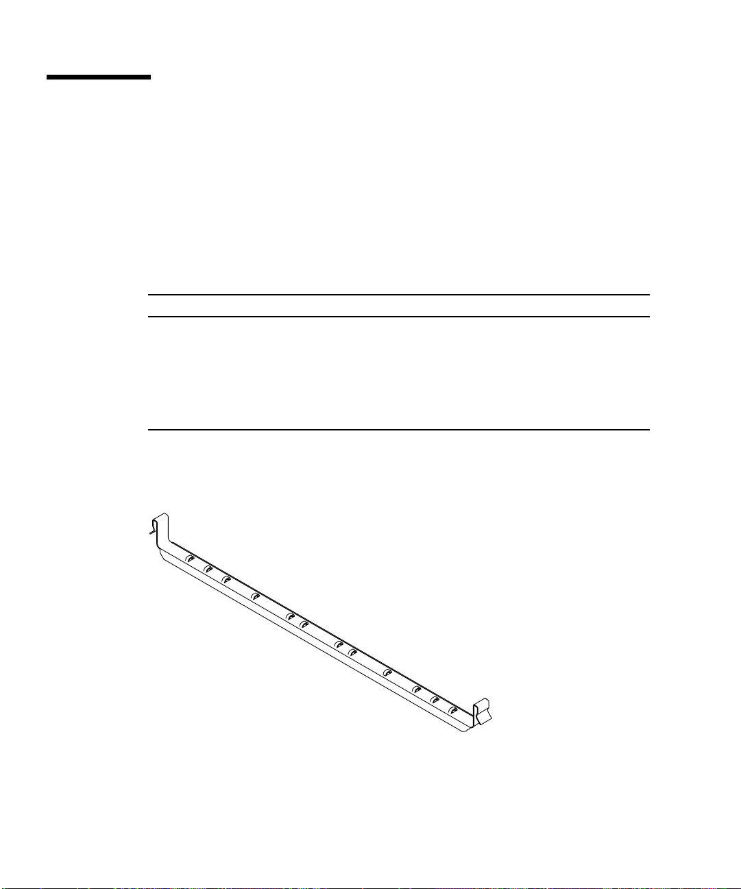
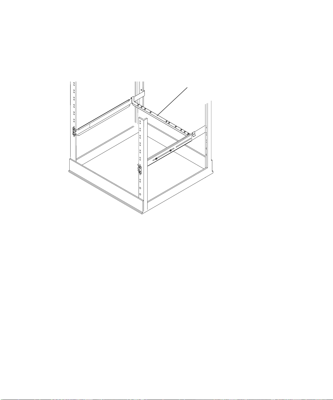
A bracket is provided to aid cable management at the rear of the system (see
FIGURE 5-1).
FIGURE 5-1 Cable Management Bracket
32 Netra t1 User and Administration Guide • June 2000

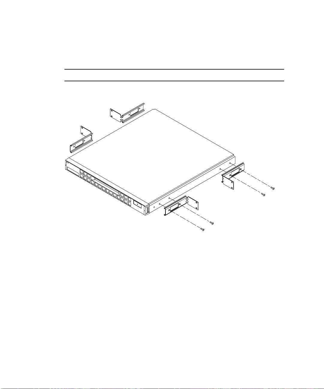
▼ To Assemble the Slides and Mount the System
1. Position the two parts of the slide so that the double-angled ear (A) is to the rear.
2. Make sure that the front and rear mounting ears are the correct distance apart, and
loosely secure the two parts together using the M4 nuts supplied (see
FIGURE 5-2 Slide Mounts for Sun 72-inch Expansion Rack
3. Adjust the mount to fit the rack.
4. Move the brackets so that the studs are in suitable slots and tighten the nuts.
5. Fasten the mounting slides to the rack using the screws supplied.
Refer to
FIGURE 5-3 and FIGURE 5-4. Leave the screws slightly loose to allow
adjustment when the Netra t1 system is inserted.
FIGURE 5-2).
A
Chapter 5 Installing the Netra t1 into a Rack 33
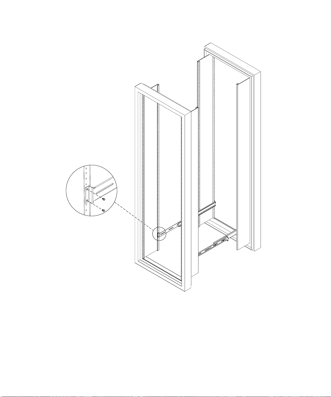
FIGURE 5-3 Fixing Slide Mounts into a Sun 72-inch Expansion Rack – Rear View (side
panels removed for clarity)
34 Netra t1 User and Administration Guide • June 2000

FIGURE 5-4 Fixing Slide Mounts into the Sun 72-inch Expansion Rack – Front View (side
panels removed for clarity)
Chapter 5 Installing the Netra t1 into a Rack 35

6. Slide the Netra t1 system into the rack.
7. Check the alignment of the thumbscrews either side of the Netra t1 system (see
FIGURE 5-5).
FIGURE 5-5 Adjusting the Mount and Tightening the Thumbscrew
8. Fasten the slide mount fixing screws.
It may be necessary to readjust the fixings in order to align the system as required.
9. Fasten the thumbscrews at the front of the Netra t1 system finger-tight (see
FIGURE 5-5).
36 Netra t1 User and Administration Guide • June 2000

▼ To Fit the Cable Management Bracket
Hook the bracket over the slide mounts at the rear of the system.
You can use the loops in the bracket to secure the cables with cable ties.
Cable management bracket
FIGURE 5-6 The Cable Management Bracket Installed in a Sun 72-inch Expansion Rack
What’s Next?
When you have installed the Netra t1 system into the rack, go to Chapter 6 for
information about connecting up the cables and setting up serial connections.
Chapter 5 Installing the Netra t1 into a Rack 37

Installing into a 19-inch Rack
The 19-inch Rack Mounting Kit
The mounting slides can each be used on either side of the rack.
The parts required are listed below:
TABLE5-2 19-inch Rack Mounting Kit
Description Quantity Part No.
Front slide 2 340-6215
Rear slide 2 340-6234
Cable management bracket 1 340-6151
M4 nuts 4 240-1373
Rack Screw Kit 1 565-1645
A bracket is provided to aid cable management at the rear of the system (see
FIGURE 5-7).
FIGURE 5-7 The Cable Management Bracket
38 Netra t1 User and Administration Guide • June 2000

▼ To Assemble the Slides and Mount the System
1. Position the two parts of the slide so that the double-angled ear (A) is to the front
(see
FIGURE 5-8).
A
FIGURE 5-8 19-inch Rack Slide Mounts
2. Make sure that the front and rear mounting ears are the correct distance apart,
then loosely secure the two parts together using the M4 nuts supplied.
3. Adjust the mount to fit the rack.
The ears must be outside the rack.
4. Move the brackets so that the studs are in suitable slots and tighten the nuts.
5. Fasten the mounting slides to the rack using the screws supplied (see
FIGURE 5-9).
Leave the screws slightly loose to allow adjustment when the Netra t1 system is
inserted.
Chapter 5 Installing the Netra t1 into a Rack 39

FIGURE 5-9 Fitting 19-inch Slide Mounts to the Rack
6. Slide the Netra t1 system into the rack (see FIGURE 5-10).
7. Check the alignment of the thumbscrews either side of the Netra t1 system (see
FIGURE 5-10).
8. Fasten the slide mount fixing screws (see
It may be necessary to readjust the fixings in order to align the system as required.
9. Fasten the thumbscrews at the front of the Netra t1 until they are finger-tight (see
FIGURE 5-10).
40 Netra t1 User and Administration Guide • June 2000
FIGURE 5-10).

FIGURE 5-10 Fitting the Netra t1 into a 19-inch Rack
Chapter 5 Installing the Netra t1 into a Rack 41
▼ To Fit the Cable Management Bracket
Hook the bracket over the slide mounts at the rear of the system.
You can use the loops in the bracket to secure the cables with cable ties.
Cable management bracket
FIGURE 5-11 The Cable Management Bracket Installed in a 19-inch Rack
What’s Next?
When you have installed the Netra t1 system into the rack, go to Chapter 6 for
information about connecting up the cables and setting up serial connections.
42 Netra t1 User and Administration Guide • June 2000

Installing into a Two-Post Relay Rack
The Fixed Mounting Bracket Kit
The parts you require are listed in TABLE 5-3.
TABLE5-3 Fixed Bracket Mounting Kit
Description Quantity Part No.
Brackets 4 340-5819
M4 x 8mm countersunk Phillips screw kit 1 565-1654
▼ To Fit the Fixed Mounting Brackets
1. Remove the thumbscrew rack mounting brackets from either side of the system
(see
FIGURE 5-12).
FIGURE 5-12 Removing the Thumbscrew Brackets
Chapter 5 Installing the Netra t1 into a Rack 43
2. Fit the two front fixed brackets to the rearmost two of the three tapped holes at the
front of the system.
Use the Phillips-head countersunk screws provided (see
FIGURE 5-13, but do NOT fit
the rear brackets yet).
Note – Do not fit the rear brackets until Step 4.
FIGURE 5-13 Fitting the Fixed Mounting Brackets
3. Now secure the system to the rack using just the front brackets, but do not fully
tighten the screws yet.
4. Fit the two rear fixed brackets to the two tapped holes at the rear of the system on
each side, using the Phillips-head countersunk screws provided.
5. Secure the rear brackets to the rack in the appropriate place (see
6. Once you are certain that all the rack fixing screws are correctly aligned, they can
be fully tightened.
44 Netra t1 User and Administration Guide • June 2000
FIGURE 5-14).
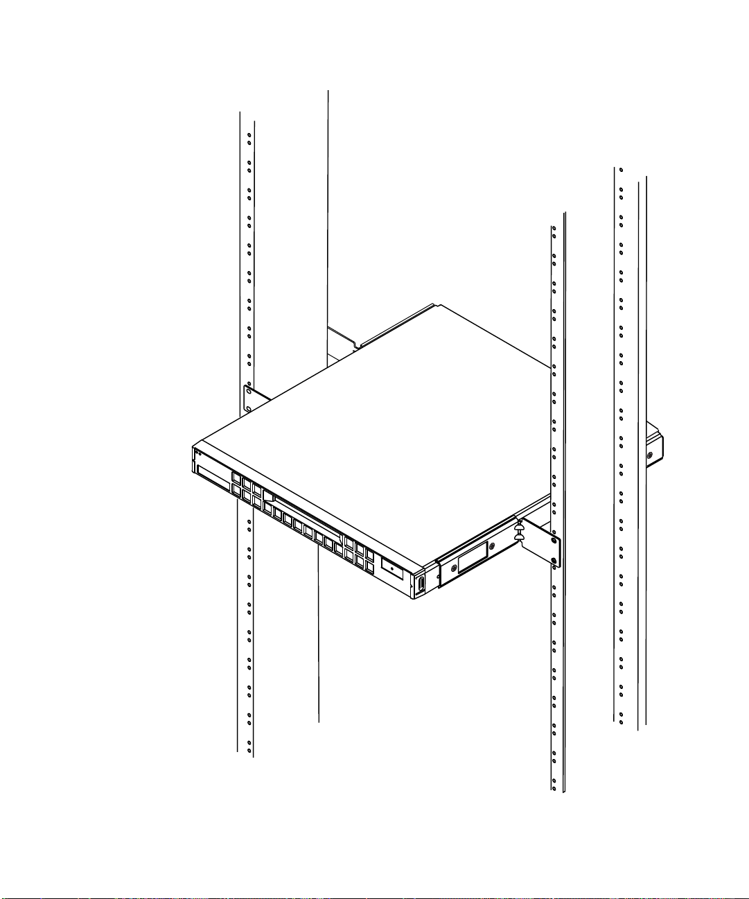
FIGURE 5-14 The Netra t1 Installed in a Two-Post Rack
Chapter 5 Installing the Netra t1 into a Rack 45

What’s Next?
When you have installed the Netra t1 system into the rack, go to Chapter 6 for
information about connecting up the cables and setting up serial connections.
46 Netra t1 User and Administration Guide • June 2000

CHAPTER
6
Connecting the Cables
This chapter tells you how to connect the power cables and the Ethernet and serial
cables to the Netra t1 system. It also tells you how to set up the serial connections
you need.
Make sure you have installed the Netra t1 system into a rack or cabinet (see
Chapter 5) before following the instructions in this chapter.
The chapter contains the following sections:
■ “Connecting the Cables to the Netra t1” on page 48
■ “Connecting the Power Cord(s)” on page 50
■ “Setting up Serial Connections” on page 52
What’s Next?
When you have followed the instructions in this chapter telling you how to connect
up the cables and set up serial connections to the Netra t1, you are ready to power
up the system. For information about powering up the system, see Chapter 7.
47
Connecting the Cables to the Netra t1
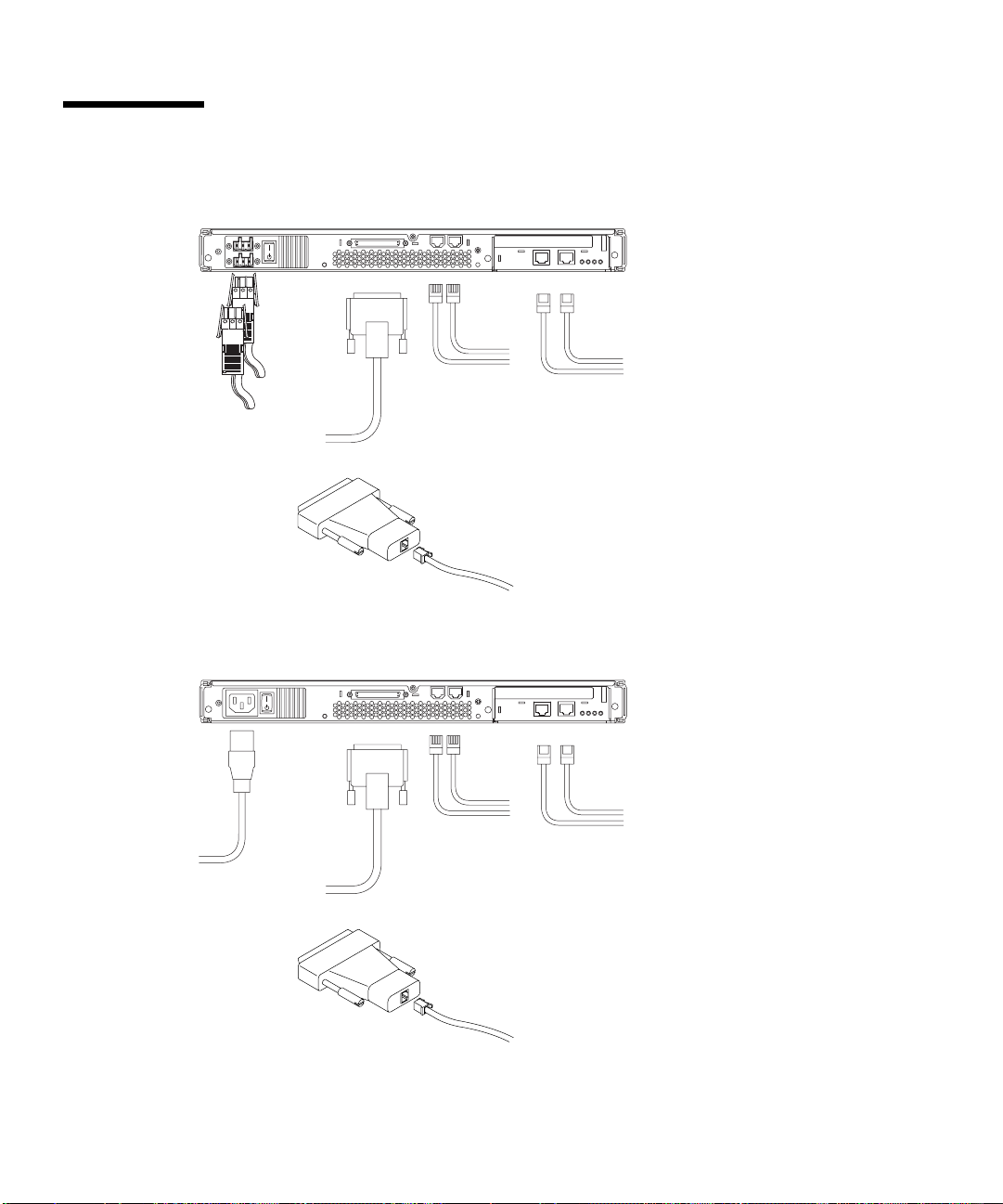
6
1
FIGURE 6-1 Connecting the Netra t1 Model 100 System
5
3
4
2
FIGURE 6-2 Connecting the Netra t1 Model 105 System
48 Netra t1 User and Administration Guide • June 2000

Before following the instructions in this section, make sure you have installed the
Netra t1 system into a rack or cabinet (see Chapter 5).
1. Connect the power cord or cords (see also
FIGURE 6-3 and FIGURE 6-4 in the next
section, “Connecting the Power Cord(s)” on page 50).
2. Connect the system to at least one Ethernet hub. You can connect to a maximum of
two.
3. Connect at least one serial device. For more information, see “Setting up Serial
Connections” on page 52.
If you want to use the Netra t1’s remote monitoring and management facilities,
make sure you use the port labeled Serial A/LOM. For more information about
remote monitoring and management, see Chapter 9.
4. If you intend to configure the Netra t1 system directly from a dumb terminal or a
Sun workstation, insert the serial cable into the DB25 adapter supplied (see
FIGURE 6-1 and FIGURE 6-2).
When you have done this, plug the adapter into the DB25 serial connector on the
terminal or Sun workstation.
5. If you need to connect the Netra t1 system to an external SCSI device, you will
need to use the SCSI cable supplied with that device.
The Netra t1’s external SCSI bus is compatible with narrow (8-bit) or wide (16-bit)
single-ended SCSI devices.
Note – If you are connecting an external SCSI device, make sure that its SCSI ID is
not 0 or 1. The Netra t1’s hard disk drives use these SCSI IDs.
6. Go to Chapter 7 which tells you how to power the system up.
7. For information about the patches you need to apply, see Chapter 8.
Chapter 6 Connecting the Cables 49
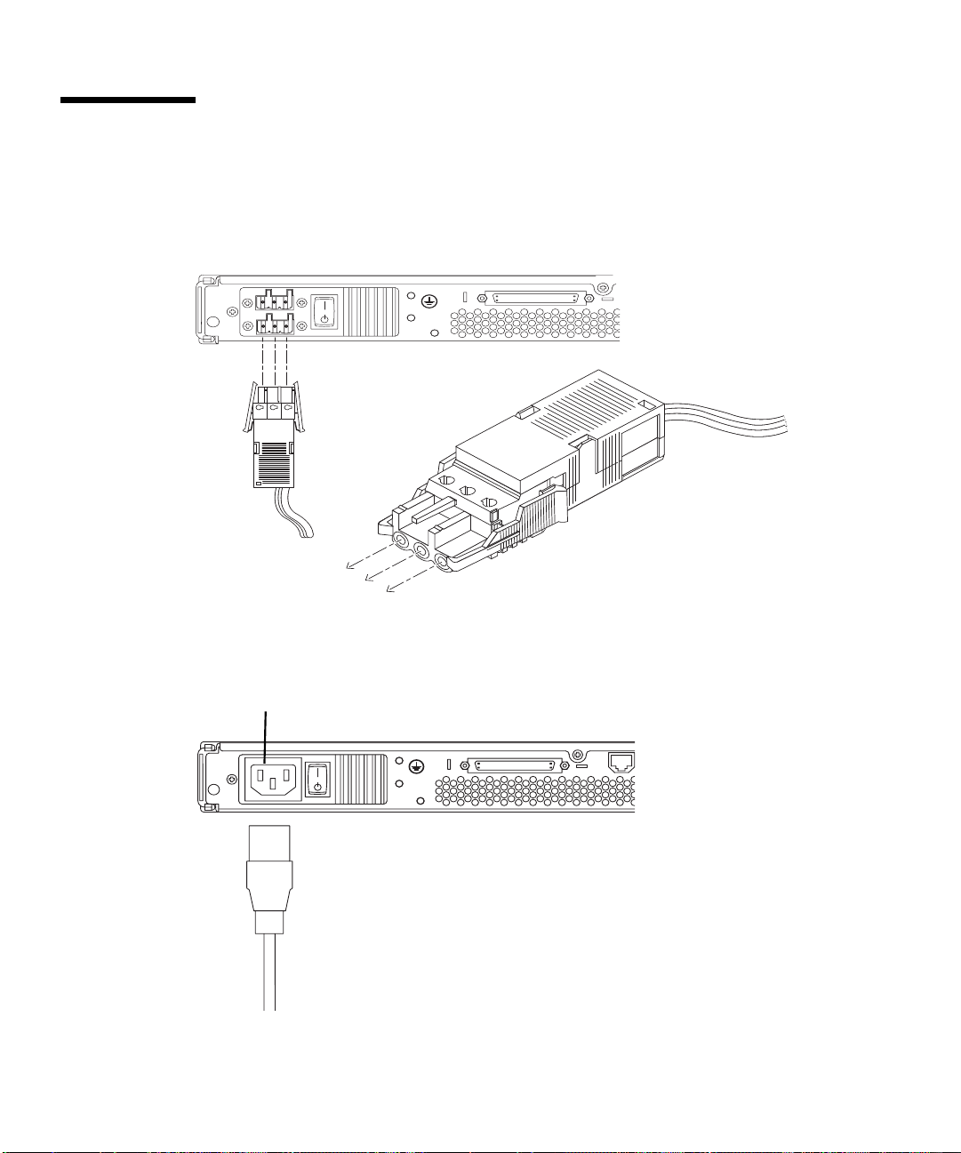
Connecting the Power Cord(s)
This section contains diagrams showing how the DC connectors for the Model 100
and the AC connector for the Model 105 connect to the system.
FIGURE 6-3 Model 100: Connecting a DC Power Cord
AC power inlet
FIGURE 6-4 Model 105: Connecting the AC Power Cord
50 Netra t1 User and Administration Guide • June 2000

Caution – AC-powered Sun products are designed to work with single-phase
power systems having a grounded neutral conductor. To reduce the risk of electric
shock, do not plug Sun products into any other type of power system. Contact your
facilities manager or a qualified electrician if you are not sure what type of power is
supplied to your building.
Caution – Your AC-powered Sun product is shipped with a grounding type (three-
wire) power cord. To reduce the risk of electric shock, always plug the cord into a
grounded outlet.
Chapter 6 Connecting the Cables 51

Setting up Serial Connections
To perform the inital configuration when you install the Netra t1 system, and also
for on-going monitoring and management of the system, you will need to use at
least one of the serial ports on the system’s rear panel. You can connect either or
both serial ports to any of the following devices:
■ A dumb terminal.
For this connection, you can use the standard RJ45 patch cable supplied with the
Netra t1 Model 100/105, but you need to insert one end into the DB25 adapter
also supplied with the Netra t1 system.
■ A Sun workstation.
For this connection, you can use the standard RJ45 patch cable supplied with the
Netra t1 Model 100/105, but you need to insert one end into the DB25 adapter
also supplied with the Netra t1 system.
■ A Terminal Server (or patch panel connected to a Terminal Server).
The pinouts for the Netra t1 system’s serial ports correspond with the pinouts for
the RJ45 ports on the Asynchronous Serial Interface Breakout Cable supplied by
Cisco for use with the Cisco L2511 Terminal Server. For terminals from other
manufacturers, you may need to make your own cross-over (null-modem) cable
(see “Cross-overs for Connecting to a Terminal Server” on page 53).
■ A modem.
For this connection, you can use the standard RJ45 patch cable supplied with the
Netra t1 Model 100/105, but you need to insert one end into the DB25 adapter
also supplied with the system. Do not connect a modem to the Serial A/LOM
port; use the Serial B port. The DTR signal asserted on the Serial A/LOM port
changes to DCD during booting or when control of the port is taken over by the
LOM device, and this can cause modem connections to be lost.
Note – The Serial A/LOM port cannot be used for binary data transfers. To perform
anything other than ASCII transfers, use the port labeled Serial B.
52 Netra t1 User and Administration Guide • June 2000

Cross-overs for Connecting to a Terminal Server
The serial ports on the Netra t1 are DTE ports. If you are connecting them to other
DTE ports, then the cabling between the devices you are connecting to each other
needs to perform a cross-over.
Note – Do not use the Serial A/LOM port for modem connections. The DTE signal
on this port changes temporarily to DCD when the Netra t1’s LOM (Lights-Out
Management) device reports an event on the serial port. This can result in the loss of
a modem connection. If you are connecting the Serial A/LOM port to a Terminal
Server, disable modem control on the Terminal Server port.
The pinouts for the Netra t1’s serial ports correspond with the pinouts for the RJ45
ports on Cisco Terminal Servers. This means, for example, that if you are using a
Cisco L2511 Terminal Server (and you are connecting the Netra t1 system to it using
the Cisco Asynchronous Serial Interface Breakout Cable), you can either:
■ connect the Breakout Cable directly to the Netra t1, or you can
■ connect the Breakout Cable to a patch panel and use the straight-through patch
cable (supplied by Sun) to connect the patch panel to the Netra t1 (see
Note – You do not have to use the Netra t1 with a Cisco Terminal Server. For other
Terminal Servers, check the manufacturer’s documentation to see if the pinouts of
the serial ports on the Terminal Server match the pinouts of the Netra t1’s serial
ports. If they do not, you need to make a cable that takes each pin on one of the
Netra t1’s serial ports to the corresponding pin in the Terminal Server ’s serial port.
FIGURE 6-5).
Cisco L2511
Asynchronous
Breakout
Cable
Patch panel
Netra t1 Server
FIGURE 6-5 Patch Panel Connection Between a Cisco L2511 and a Netra t1 System
Chapter 6 Connecting the Cables 53

Note – When viewed from the rear of the Netra t1 system, pin 1 of the RJ45 serial
port is on the left, pin 8 on the right.
81
FIGURE 6-6 Serial Port Pins 1 to 8
TABLE6-1 Pin Cross-overs for Connecting to a Typical Terminal Server
Netra t1 Serial Port (RJ45 Connector) Pin Terminal Ser ver Serial Port Pin
Pin 1 (RTS) Pin 1 (CTS)
Pin 2 (DTR) Pin 2 (DSR)
Pin 3 (TXD) Pin 3 (RXD)
Pin 4 (Signal Ground) Pin 4 (Signal Ground)
Pin 5 (Signal Ground) Pin 5 (Signal Ground)
Pin 6 (RXD) Pin 6 (TXD)
Pin 7 (DSR) Pin 7 (DTR)
Pin 8 (CTS) Pin 8 (RTS)
54 Netra t1 User and Administration Guide • June 2000

Using a DB25 Adapter for Your Serial Link
The pinouts are identical for both of the RJ45 serial ports on the Netra t1 system. To
connect to a UNIX tip session or a vt100 terminal, you need to use either the DB25
(25-Pin DSUB Male to 8-POS RJ45 Female) adapter that is supplied by Sun (part no.
530-2889) with your system, or an alternative adapter that performs the same pin
cross-overs. The Sun-supplied DB25 adapter enables you to connect to any Sun
system. The cross-overs it performs are listed in
Note – If you need to set up a modem connection to the Netra t1 system, you must
use the port labeled Serial B. The Serial A/LOM port does not assert the required
constant DTR signal.
Note – When viewed from the rear of the Netra t1 system, pin 1 of the RJ45 serial
port is on the left, pin 8 on the right.
81
FIGURE 6-7 Pins 1 to 8 on the Serial Ports
TABLE 6-2.
TABLE6-2 Pin Cross-overs in the Sun DB25 (25-pin) Adapter
Serial Port (RJ45 Connector) Pin 25-pin Connecter
Pin 1 (RTS) Pin 5 (CTS)
Pin 2 (DTR) Pin 6 (DSR)
Pin 3 (TXD) Pin 3 (RXD)
Pin 4 (Signal Ground) Pin 7 (Signal Ground)
Pin 5 (Signal Ground) Pin 7 (Signal Ground)
Pin 6 (RXD) Pin 2 (TXD)
Pin 7 (DSR) Pin 20 (DTR)
Pin 8 (CTS) Pin 4 (RTS)
Chapter 6 Connecting the Cables 55

Using a DB9 Adapter for Your Serial Link
To connect to a terminal that has a 9-pin serial connector, connect one of the Netra
t1’s serial ports to a DB9 (9-pin) adapter that performs the pin cross-overs listed in
TABLE 6-3.
Note – When viewed from the rear of the Netra t1 system, pin 1 of the RJ45 serial
port is on the left, pin 8 on the right.
81
FIGURE 6-8 Pins 1 to 8 on the Serial Ports
TABLE6-3 Pin Cross-overs for a DB9 (9-pin) Adapter
Serial Port (RJ45 Connector) Pin 9-pin Connector
Pin 1 (RTS) Pin 8 (CTS)
Pin 2 (DTR) Pin 6 (DSR)
Pin 3 (TXD) Pin 2 (RXD)
Pin 4 (Signal Ground) Pin 5 (Signal Ground)
Pin 5 (Signal Ground) Pin 5 (Signal Ground)
Pin 6 (RXD) Pin 3 (TXD)
Pin 7 (DSR) Pin 4 (DTR)
Pin 8 (CTS) Pin 7 (RTS)
56 Netra t1 User and Administration Guide • June 2000

Settings for the Serial Connections
The settings you need to use for a serial connection are listed in TABLE 6-4. If you
need to perform binary data transfers (that is, transfers of anything more than
simple ASCII character streams), use the Serial B port. Communication on the Serial
A/LOM port is subject to interruption by the ‘Lights-Out’ Management (LOM)
device (see Chapter 9).
TABLE6-4 Settings for Connecting to the Serial A/LOM or Serial B Port
Parameter Setting
Connector: Serial A/LOM or Serial B (use Serial B for binary data transfers)
Rate: 9600 baud
Parity: No
Stop bits: 1
Data bits: 8
What’s Next?
When you have connected up the cables and set up serial connections to the Netra
t1, you are ready to power up the system. For information about powering up the
system, see Chapter 7.
Chapter 6 Connecting the Cables 57

58 Netra t1 User and Administration Guide • June 2000

CHAPTER
7
Powering Up the Netra t1
This chapter tells you how to power up the Netra t1 system.
The chapter contains the following sections:
■ “Powering Up and Configuring for the First Time” on page 60
■ “Using the Power (On/Standby) Switch” on page 63
What’s Next?
When you have followed the instructions in this chapter telling you how to power
on the system, and when you have booted and logged in, go to Chapter 8 for
information about using different versions of Solaris.
For information about monitoring and managing the Netra t1, see Chapter 9.
For information about Troubleshooting, see Chapter 11.
59

Powering Up and Configuring for the First Time
To perform the initial configuration of the Netra t1 system, set up a serial connection
via the port labeled Serial A/LOM on the Netra t1 (see Chapter 6).
Make sure you have the Netra t1’s power cord or cords connected (see Chapter 6).
Configuring via a Terminal Server
To access the Netra t1 system from a Sun workstation via a Terminal Server, open a
Terminal Session on the Sun workstation, and type:
# telnet <IP address of Terminal Server> <port number>
For example, for a Netra t1 system connected to port 10000 on a Terminal Server
whose IP address is 192.20.30.10, you would type:
# telnet 192.20.30.10 10000
Configuring from a Terminal or Workstation
To access the Netra t1 system from a dumb terminal just set up a connection between
the terminal and the Netra t1 system.
To access the Netra t1 system from a Sun workstation directly connected to the
system, set up the connections between the devices and run a terminal session. Note,
however, that before you can connect to the Netra t1 system’s Serial A/LOM port
from a Sun workstation, you must edit the hardwire: line in your /etc/remote
file. By default, this line looks as follows:
hardwire:\:dv=/dev/term/b:br#9600:el=^C^S^Q^U^D:ie=%$:oe=^D
60 Netra t1 User and Administration Guide • June 2000
You must replace the letter b ( after term/ and before the third colon) with the letter
a, so that the line looks as follows:
hardwire:\:dv=/dev/term/a:br#9600:el=^C^S^Q^U^D:ie=%$:oe=^D
▼ To Power the System Up for the First Time
Before following the instructions in this section, read them to find out what
information the system prompts you for when you start it for the first time.
With the system connected to the power supply but not powered up, and with a
serial connection to the Serial A/LOM port and a connection to at least one Ethernet
hub (as described in Chapter 6), follow the instructions below:
1. At the lom> prompt which automatically appears in your Terminal screen, type
the following command to power on the system:
lom> poweron
For more information about the lom> prompt and the commands that are available
from it, see Chapter 9.
2. During booting you will be prompted for certain information.
The first question the system asks you is what language you want it to use when it
prompts you for the information it needs. Specify a language.
3. Next specify your locale.
4. Specify the type of terminal you are using to communicate with the Netra t1.
5. Specify a Host Name for the system.
6. When asked if you are connected to the network by a Solaris-supported Ethernet
card, answer Yes.
7. Specify which of the Ethernet ports you intend to use as the primary Ethernet
connection.
For the port labeled Net0, specify hme0. For the port labeled Net1, specify hme1.
8. Specify a valid IP address for the system.
9. Specify the Name Service you want the system to use.
10. Specify the name of the Domain that the system will be a part of.
Chapter 7 Powering Up the Netra t1 61

11. Specify whether you want the system to search the network for a Name Server or
whether you want it to use a particular Name Server.
12. If you chose to use a particular Name Server, specify the Host Name and IP
address of the Name Server.
13. Specify whether the Netra t1 system is to be part of a subnet.
14. Specify a Netmask for the system.
15. Confirm the information you have typed in and, when prompted, provide the time
and date information the system needs.
16. When prompted, give a password (if any) for users logging in as root.
17. When asked if you want the sytem to perform Automatic Power Saving
Shutdown, answer No.
Note – If you answer Yes, the system will automatically put itself into Standby
mode after a period of idleness.
18. When you have provided the information the system needs, it will boot.
What’s Next?
When you have powered on the system and booted and logged in, go to Chapter 8
for information about using different versions of Solaris.
For information about monitoring and managing the Netra t1, see Chapter 9.
For information about Troubleshooting, see Chapter 11.
62 Netra t1 User and Administration Guide • June 2000
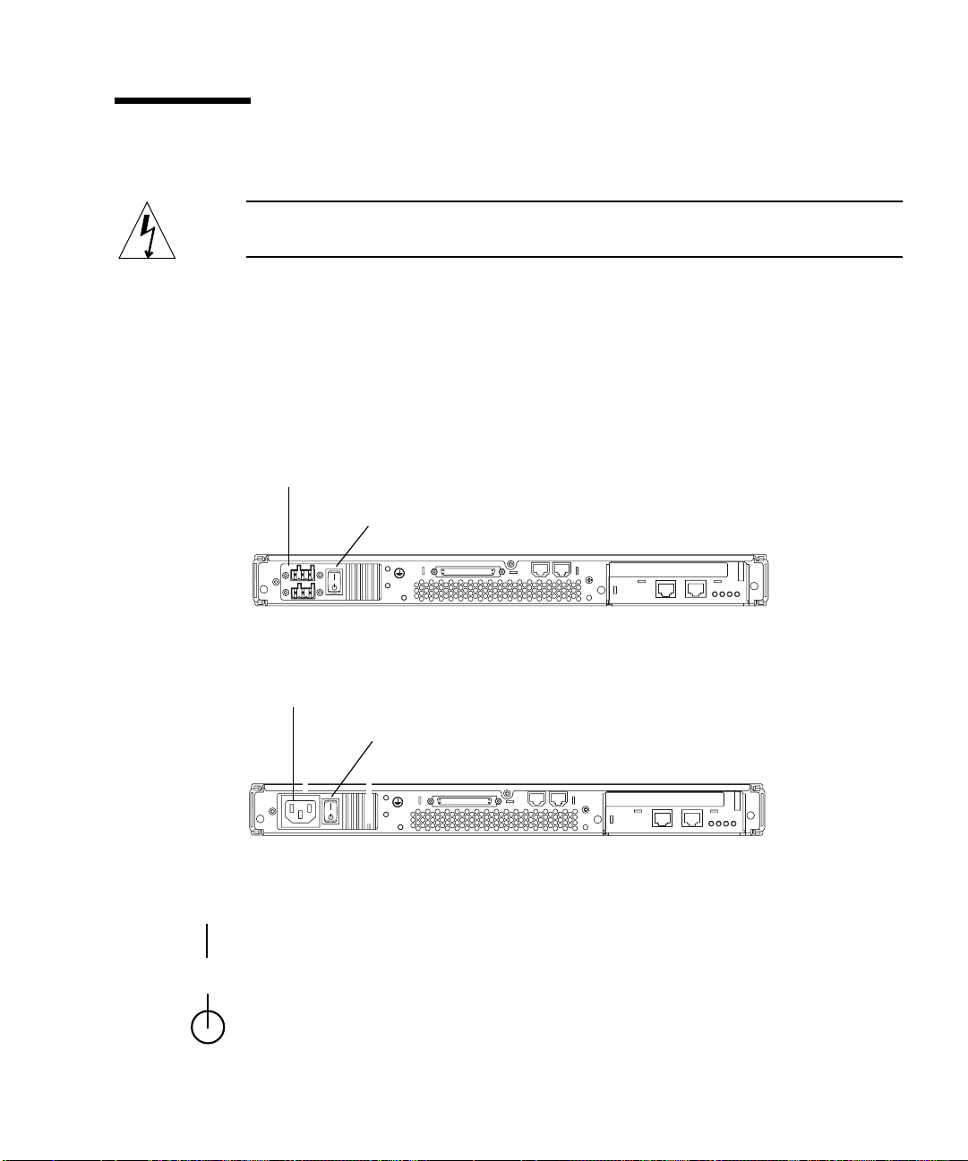
Using the Power (On/Standby) Switch
Caution – The power switch (on the rear panel of the Netra t1 system) is not an
On/Off switch, it is an On/Standby switch. It does not isolate the equipment.
The power (On/Standby) switch of the Netra t1 system is a rocker, momentary
switch. It controls only low voltage signals; no high-voltage circuits pass through it.
This means that the main method of connecting or disconnecting power is by
inserting or removing the power supply cord(s). The system contains no integral
circuit breakers. To isolate it, you must break all connections to it. If you do not do
this by removing the power supply cord(s), you must instead open all external
circuit breakers.
DC power inlets
Power (On/Standby) switch
FIGURE 7-1 Model 100 System Switch
AC power inlet
Power (On/Standby) switch
FIGURE 7-2 Model 105 System Switch
The symbols on the switch are as follows:
On – Press this to apply power to the system.
Standby – Press this to put the system into Standby mode.
Chapter 7 Powering Up the Netra t1 63

64 Netra t1 User and Administration Guide • June 2000

CHAPTER
8
Using Different Versions of Solaris
Note – The Netra t1 ships with Solaris 7 (11/99) pre-installed and fully patched. If
you do not intend to alter this configuration of the Netra t1, skip this chapter.
This chapter tells you how to install Solaris 2.6 onto a Netra t1. The instructions
require you to use the bootable Solaris Operating Environment Installation CD 9/99
(part no. 704-6914-10) supplied with the Netra t1.
Although the Netra t1 ships with Solaris 7 pre-installed and patched, this chapter
refers you to the documentation supplied with Solaris 7 and Solaris 8 if you need to
install either of those operating systems yourself (for example, if you install Solaris
2.6 but then decide to upgrade to Solaris 7 or 8). The Solaris 7 and 8 installations are
standard procedures involving no supplementary CD. We recommend you install
Solaris 7 (11/99 or later).
The chapter goes on to tell you which patches you need to apply if you install
Solaris 2.6, 7 or 8 yourself (instead of using the system as configured and patched by
Sun during manufacturing).
The chapter contains the following sections:
■ “Installing Solaris release 2.6” on page 66
■ “Installing Solaris release 7 or 8” on page 68
■ “The Patches You Need” on page 68
65

Installing Solaris release 2.6
This section tells you how to install release 2.6 of the Solaris operating environment
onto a Netra t1 Model 100/105 system.
Note – The Netra t1’s factory-installed software includes the ‘Lights-Out’
Management software. If you install a new operating system and you want to use
the ‘Lights-Out’ Management facilities described in Chapter 9, you must re-install
the ‘Lights-Out’ Management software. This is available on a CD (part number:
X6972A) from your Sun Enterprise Services representative.
▼ To Install Solaris 2.6 from the CDs
Before you begin the installation process, make sure you have the:
■ Two Solaris 2.6 (5/98) CDs (part no. 704-6220-10)
■ Solaris Operating Environment Installation CD 9/99. This CD is supplied with
the Netra t1 (part no. 704-6914-10). It includes the kernel update patch (105181-xx)
you need for running Solaris 2.6 on a Netra t1 system.
For information about what to type when you want to boot from the CD, see “Patch
108620-04: How to Boot from a CD” on page 69.
Note – To make sure all the most recent patches on the Solaris 2.6 (5/98) CDs are
applied, install the entire distribution plus OEM support.
1. Insert the Solaris Operating Environment Installation CD into the CD-ROM drive
and, at the ok prompt, type the following (but refer to the section called “Patch
108620-04: How to Boot from a CD” on page 69):
ok boot cdrom
2. Follow the instructions displayed on the console.
These tell you when to insert the Solaris 2.6 (5/98) CDs.
66 Netra t1 User and Administration Guide • June 2000

▼ To Install Solaris 2.6 from the Network
Note – To make sure all the most recent patches on the Solaris 2.6 (5/98) CDs are
applied, install the entire distribution plus OEM support.
Before following the instructions below, make a note of the MAC address of the
system you are installing Solaris 2.6 onto. This is displayed on the banner that
appears on your console when you boot the system.
1. On another Solaris system, which must be on the same network as the Netra t1
system you are installing Solaris 2.6 onto, create a Solaris 2.6 (5/98) net install
server. Do this by following the instructions supplied with the Solaris 2.6 (5/98)
CDs.
Because the instructions below require you to install software from a second CD (the
Solaris Operating Environment Installation CD) onto the system you are using as the
net install server, you cannot leave the Solaris 2.6 (5/98) CD in the CD drive.
Instead, therefore, you must copy the install image from the Solaris 2.6 (5/98) CD
onto the local disk of the system you are using as the net install server.
2. When the install server setup is complete, remove the Solaris 2.6 (5/98) CD and
insert the Solaris Operating Environment Installation CD.
3. Run the modify_install_server script.
For information about running this script, refer to the documentation provided with
the Solaris 2.6 (5/98) CDs. Running this script with the Solaris Operating
Environment Installation CD inserted updates the net install server with the patches
required for the Netra t1.
4. Register the Netra t1 Model 100/105 with the net install server by running the
add_install_client script on that server.
For more information about running the add_install_client script, refer to the
documentation provided with the Solaris 2.6 (5/98) CD.
5. On the Netra t1 Model 100/105 that you are installing Solaris 2.6 onto, make sure
that the autoboot? environment variable is set to true. To do this, type:
ok autoboot?=true
6. Make sure the Netra t1 Model 100/105 you are installing Solaris onto does not
contain a valid system disk from which to boot. Or, if it does, break to the ok
prompt and type:
ok boot net
Chapter 8 Using Different Versions of Solaris 67

7. Power up the Netra t1 Model 100/105. When you do this, the system will
automatically attempt to boot from the network.
8. Follow the instructions on the console for a standard installation.
For more information, refer to the documentation provided with Solaris 2.6 (5/98).
Installing Solaris release 7 or 8
The Netra t1 system is supplied with Solaris 7 (11/99) already installed and patched.
To re-install Solaris 7 (for example, after having previously installed Solaris 2.6) or to
install Solaris 8, follow the instructions in the documentation provided with your
Solaris 7 or 8 CD. These installations are standard procedures and do not involve
supplementary installation CDs.
If you are installing Solaris 7, we recommend you install the version dated 11/99 or
later.
Note – The Netra t1’s factory-installed software includes the ‘Lights-Out’
Management software. If you install a new operating system and you want to use
the ‘Lights-Out’ Management facilities described in Chapter 9, you must re-install
the ‘Lights-Out’ Management software. This is available on a CD (part number:
X6972A) from your Sun Enterprise Services representative.
The Patches You Need
TABLE 8-1 tells you which patches you need to apply to run the different versions of
Solaris on a Netra t1 Model 100/105. The latest versions of each patch are available
from your local Sun Enterprise Services representative or from SunSolve:
http://www.sun.com/sunsolve
Note – If you are using the factory-installed system software, you do not need to
apply any patches. They have been applied for you already.
68 Netra t1 User and Administration Guide • June 2000

TABLE8-1 Patches Required for Solaris 2.6 (5/98), or Solaris 7 or 8
Software Affected Number of Patch Required for Solaris 2.6 (5/98), Solaris 7 or Solaris 8
LOMlite 108146-02 (Available on SunSolve)
UserPROM 108620-04 (Available on SunSolve)
SystemPROM 108673-01 (Available on SunSolve)
Patch 108620-04: How to Boot from a CD
Booting with the Patch Applied
If you have patch 108620-04 applied, this section tells you what you need to type to
boot from the CD-ROM drive you are using. (Note that the Netra t1 now ships with
this patch already applied.)
If you are booting from an internal CD-ROM drive, type:
ok boot cdrom
If you are booting from an external CD-ROM drive in a Netra t1 system that does
not contain an internal CD-ROM drive, type:
ok boot cdrom
If you are booting from an external CD-ROM drive and your Netra t1 system also
contains an internal CD-ROM drive, type:
ok boot cdrom1
Chapter 8 Using Different Versions of Solaris 69

Booting Without the Patch Applied
If you are configuring an earlier Netra t1 system that does not have patch 108620-04
applied, this section tells you what you need to type to boot from the CD-ROM drive
you are using.
If you are booting from an internal CD-ROM drive, type:
ok boot cdrom
If you are booting from an external CD-ROM drive, type:
ok boot cdrom1
Patch 108673-01: Setting Environment Variables
Note – If you have patch 108673-01 applied, you do not need to set any
environment variables. Note that the Netra t1 now ships with this patch already
applied. You only need to follow the instructions below if you do not have patch
108673-01 applied to the operating system.
Patch 108673-01 contains a version of the Sun OpenBoot
specifically for the Netra t1. It is required because the default parameter settings in
versions of the OBP software used on other Sun platforms are not correct for the
Netra t1.
This means that, if you do not have patch 108673-01 applied, you must set certain
OBP parameters manually for the Netra t1. It also means that, if you use the
set-defaults command after setting these parameters manually, you must set
them manually again. (The set-defaults command returns the OBP parameters to
their defaults. Unless you have patch 108673-01 applied, these defaults will not be
correct for the Netra t1.)
The OBP parameters are stored in NVRAM on the motherboard. To make sure they
are correct for a Netra t1 system that does not have patch 108673-01 applied, do the
following:
1. Return the OBP parameters to their standard settings by typing:
ok set-defaults
70 Netra t1 User and Administration Guide • June 2000
TM
PROM (OBP) software

2. Type the following commands:
ok setenv pcib-probe-list 1,2,3
ok setenv output-device ttya
ok setenv input-device ttya
Note – Whenever you use the set-defaults command from the ok prompt, make
sure you afterwards set the variables listed in Step 2 above.
Chapter 8 Using Different Versions of Solaris 71

72 Netra t1 User and Administration Guide • June 2000

PART
II Maintenance and Management


CHAPTER
9
Monitoring and Managing the System
This chapter describes the Netra t1 system’s remote monitoring and management
facility. It contains the following sections:
■ “What You Can Use the ‘Lights-Out’ Management (LOM) Facility For” on page 76
■ “How the LOM Device Sends its Event Reports” on page 77
■ “Interrogating the LOM and Using it to Power Up or Reset the System” on
page 79
■ “Configuring the LOM to Restart the System Automatically After a Lock-up” on
page 84
■ “Other Ways of Configuring the LOM” on page 85
■ “Utilites Associated with the LOM Device” on page 86
■ “The System’s Front and Back Panel LEDs” on page 87
■ “The Fans Monitored by the LOM Device” on page 88
75

What You Can Use the ‘Lights-Out’ Management (LOM) Facility For
The Netra t1 includes a management facility which allows you to detect and respond
quickly to problems with the Power Supply Unit (PSU) or fans. It is particularly
useful for monitoring servers remotely that are deployed in a “lights out”
environment. But you can also use it to perform quick onsite management tasks via
a local serial connection.
This management facility is provided by a device on the Netra t1’s motherboard
called the Lights-Out Management (LOM) device and by software that is preinstalled on your system during manufacturing.
Note – If you install new system software onto the Netra t1 and you want to
continue using the Lights-Out Management facility, you must re-install the LOM
software. A CD containing the software is available from your Sun Enterprise
Services representative (part number: X6972A).
You can use the LOM facility to:
■ Monitor the status of the power supply, fans, fault LED and alarms even when the
system is powered down.
■ Power the system up and down.
■ Turn a Fault LED on (for example, to enable you to identify a particular system in
a rack containing a number of Netra t1s).
You can also configure the LOM device on the Netra t1 to perform an automatic
system restart in the event of a lock-up.
76 Netra t1 User and Administration Guide • June 2000

How the LOM Device Sends its Event Reports
The LOM device monitors the status of the fans and the power supply even when
the system is powered down (the LOM device operates on standby power). If it
detects a fault, it turns on the Fault LED on the system’s front and rear panels and
stores a report in an event log which resides in memory on the LOM device itself.
What it does next depends on whether the operating system is running with a
daemon called lomlited enabled:
■ If your Netra t1 system is running the factory-installed system software, then the
Lights-Out Management software, including the lomlited daemon, is fully
installed and enabled.
■ If you are not running the factory-installed system software (but are running
another configuration of Solaris), then you need to re-install the Lights-Out
Management software from a CD (part number: X6972A) that is available from
your Sun Enterprise Services representative.
When the Operating System is Running and the lomlited Daemon is Installed and Running
When the operating system is running and the lomlited daemon is enabled, the
LOM device is monitored by the lomlited daemon. This daemon sends LOM event
reports to syslogd giving them the identifier string lomlited. syslogd handles
them in the way it is configured to handle event reports (by default, it sends them to
the console and stores them in /var/adm/messages).
The lomlited daemon is started by an rc script. The daemon is stored in /etc/
init.d.
When the lomlited Daemon is Not Running
The lomlited daemon does not monitor the LOM device when:
■ The operating system is not running (for example, when the ok prompt is
displayed on your console).
■ You have disabled the lomlited daemon.
■ You have installed new operating system software (over the factory-installed
system software) but have not manually re-installed the LOMlite software.
Chapter 9 Monitoring and Managing the System 77

In any of these circumstances, when the lomlited daemon is not running and an
event affecting the fans or power supply occurs, the LOM device takes control of the
Serial A/LOM port and sends an event report onto that port. When it has sent the
report, the LOM device relinquishes control of the serial port. Note that this can
interfere with communication on the Serial A/LOM port (see note below).
Note – LOM reports that occur when the lomlited daemon is not running can
interfere with communication on the Serial A/LOM port. If you do not have the
lomlited daemon installed and enabled then, to prevent the LOM from
interrupting serial communication, either use the Serial B port as your console port
or turn off LOM event reporting (see “Stopping the LOM from Sending Reports to
the Serial A Port When the Daemon is not Running” on page 78”).
Capturing LOM Event Reports Passively on the Serial A/LOM Port
To monitor LOM events as they occur, keep a terminal connected to Serial Port A.
For information about setting up serial connections to the Netra t1, see Chapter 6.
For information about using LOM commands to interrogate the LOM device, see
“Interrogating the LOM and Using it to Power Up or Reset the System” on page 79.
Stopping the LOM from Sending Reports to the Serial A Port When the Daemon is not Running
LOM reports that occur when the lomlited daemon is not running can interfere
with information you are attempting to send or receive on the Serial A/LOM port.
If you do not have the LOM software installed or you have disabled the lomlited
daemon, you might want to stop the LOM device from sending reports to the Serial
A/LOM port.
To do this, use the lomctl utility stored in the /usr/bin directory.
To turn off reporting to the serial port, type:
# lomctl serialeventsoff
78 Netra t1 User and Administration Guide • June 2000
 Loading...