

Page 1

Netra™CT Server Service Manual
For the Netra CT 810 Server and Netra CT 410 Server
Sun Microsystems, Inc.
www.sun.com
Part No. 819-2741-10
February 2007, Revision A
Submit comments about this document at: http://www.sun.com/hwdocs/feedback
Page 2

Copyright 2007Sun Microsystems,Inc., 4150 Network Circle, SantaClara, California95054, U.S.A. Allrights reserved.
Sun Microsystems, Inc.has intellectual property rights relating to technologythat isdescribed in thisdocument. Inparticular, and without
limitation, theseintellectual propertyrights may include one ormore ofthe U.S. patentslisted athttp://www.sun.com/patentsand one or
more additional patents orpending patent applications in theU.S. and in other countries.
This documentand the product to which it pertainsare distributedunder licenses restricting theiruse, copying,distribution, and
decompilation. Nopart of the product or of thisdocument may be reproduced in any formby any means without priorwritten authorizationof
Sun andits licensors, if any.
Third-party software, including fonttechnology, iscopyrighted andlicensed from Sun suppliers.
Parts ofthe productmay be derived from BerkeleyBSD systems,licensed from the University ofCalifornia. UNIX is a registered trademark in
the U.S.and in other countries, exclusivelylicensed throughX/Open Company,Ltd.
Sun, SunMicrosystems, theSun logo, Java, docs.sun.com, Netra,Solstice DiskSuite, SunVTS, OPenBoot, andSolaris aretrademarks or
registered trademarks of SunMicrosystems, Inc.in the U.S. and inother countries.
All SPARCtrademarks areused under license and are trademarksor registeredtrademarks ofSPARCInternational, Inc. inthe U.S.and in other
countries. Products bearingSPARCtrademarks arebased upon an architecture developed by SunMicrosystems, Inc.
The OPENLOOK and Sun™ Graphical UserInterface was developed by SunMicrosystems, Inc.for its users and licensees. Sun acknowledges
the pioneeringefforts ofXerox inresearching anddeveloping the concept of visualor graphical user interfaces forthe computer industry.Sun
holds anon-exclusive license from Xeroxto the Xerox GraphicalUser Interface,which license also covers Sun’slicensees who implement OPEN
LOOK GUIsand otherwise comply with Sun’swritten license agreements.
U.S. GovernmentRights—Commercial use.Government users are subject tothe SunMicrosystems, Inc. standard license agreement and
applicable provisions ofthe FAR and its supplements.
DOCUMENTATION IS PROVIDED "AS IS" AND ALL EXPRESS OR IMPLIED CONDITIONS, REPRESENTATIONS AND WARRANTIES,
INCLUDING ANYIMPLIED WARRANTY OFMERCHANTABILITY,FITNESS FOR A PARTICULAR PURPOSE OR NON-INFRINGEMENT,
ARE DISCLAIMED, EXCEPT TO THE EXTENT THAT SUCH DISCLAIMERS ARE HELD TO BE LEGALLY INVALID.
Copyright 2007Sun Microsystems,Inc., 4150 Network Circle, SantaClara, Californie95054, Etats-Unis. Tous droits réservés.
Sun Microsystems, Inc.a les droits de propriété intellectuels relatants à latechnologie qui est décrit dansce document. En particulier,et sans la
limitation, cesdroits depropriété intellectuelspeuvent inclure un ou plusdes brevetsaméricains énumérés à http://www.sun.com/patents et
un oules brevetsplus supplémentairesou les applicationsde breveten attente dans les Etats-Uniset dans les autres pays.
Ce produit oudocument est protégé par un copyright etdistribué avec des licences quien restreignentl’utilisation, la copie, la distribution,et la
décompilation. Aucunepartie de ce produit ou document nepeut êtrereproduite sousaucune forme, par quelque moyenque ce soit, sans
l’autorisation préalableet écrite de Sun etde ses bailleurs de licence,s’il yen a.
Le logicieldétenu par des tiers, etqui comprendla technologie relative aux policesde caractères,est protégépar un copyright et licenciépar des
fournisseurs deSun.
Des partiesde ce produit pourrontêtre dérivées des systèmes BerkeleyBSD licenciés par l’Université deCalifornie. UNIX est une marque
déposée auxEtats-Unis et dans d’autres pays et licenciéeexclusivement par X/Open Company, Ltd.
Sun, SunMicrosystems, lelogo Sun, Java, docs.sun.com, Netra,Solstice DiskSuite, SunVTS, OPenBoot, etSolaris sont des marques de fabrique
ou desmarques déposéesde Sun Microsystems, Inc. auxEtats-Unis etdans d’autres pays.
Toutes les marquesSPARCsont utilisées sous licence etsont desmarques de fabrique ou desmarques déposéesde SPARC International, Inc.
aux Etats-Uniset dans d’autres pays. Les produits portantles marquesSPARCsont basés sur une architecture développée par Sun
Microsystems, Inc.
L’interfaced’utilisation graphiqueOPEN LOOK etSun™ aété développée par Sun Microsystems,Inc. pourses utilisateurs etlicenciés. Sun
reconnaît les efforts depionniers deXerox pour la recherche et le développementdu conceptdes interfaces d’utilisationvisuelle ougraphique
pour l’industriede l’informatique. Sun détient unelicense non exclusive de Xerox surl’interface d’utilisationgraphique Xerox, cette licence
couvrant égalementles licenciées de Sun quimettent en place l’interface d’utilisation graphiqueOPEN LOOK etqui enoutre se conforment
aux licencesécrites de Sun.
LA DOCUMENTATION EST FOURNIE "EN L’ÉTAT" ET TOUTES AUTRES CONDITIONS, DECLARATIONS ET GARANTIES EXPRESSES
OU TACITES SONT FORMELLEMENT EXCLUES, DANSLA MESUREAUTORISEE PAR LA LOI APPLICABLE, YCOMPRIS NOTAMMENT
TOUTE GARANTIE IMPLICITE RELATIVE A LA QUALITE MARCHANDE, A L’APTITUDE A UNE UTILISATION PARTICULIERE OU A
L’ABSENCE DE CONTREFAÇON.
Please
Recycle
Page 3

Contents
Preface xxi
Part 1 Preparing for Service
1. Preparing for FRU Installation and Replacement 1–1
1.1 Tools Required 1–2
1.2 Attaching the Antistatic Wrist Strap 1–2
1.3 FRU Categories 1–3
1.3.1 Hot-Swappable FRUs 1–4
1.3.2 Cold-Swappable FRUs 1–4
1.4 Device Names 1–5
1.4.1 Device Names for I/O Board Slots in the Netra CT Servers 1–5
1.4.2 Device Names for hard drives 1–6
2. Powering the Server Off and On 2–1
2.1 Powering On the Server 2–2
2.2 Verifying Full Power-Up 2–6
2.3 Powering Off the Server 2–7
2.3.1 To Perform a Hardware Power-Down 2–7
2.3.2 To Perform a Software Power Down 2–8
iii
Page 4

3. Handling Boards and Assemblies 3–1
3.1 Handling Boards 3–2
3.2 Handling Assemblies 3–3
Part 2 Troubleshooting the System
4. Troubleshooting the System 4–1
4.1 Troubleshooting the System Using the System Status Panel 4–2
4.1.1 Locating and Understanding the System Status Panel 4–2
4.1.2 Using the System Status Panel LEDs to Troubleshoot the System
4–3
4.2 Troubleshooting the System Using prtdiag 4–9
4.3 Troubleshooting the System Using Diagnostic Software 4–14
4.4 Troubleshooting the System Using the Power-On Self Test (POST) 4–16
4.5 Troubleshooting the System Using the Alarm Card Software 4–18
4.6 Troubleshooting a Power Supply Using the Power Supply UnitLEDs 4–18
4.6.1 Troubleshooting the Power Supply Unit in the Netra CT 410
Server 4–18
4.6.2 Troubleshooting the Power Supply Units in the Netra CT 810
Server 4–19
4.7 Troubleshooting a Host CPU Board 4–20
4.7.1 General Troubleshooting Tips 4–20
4.7.2 Warning, Critical, and Shutdown Temperatures 4–22
4.7.3 General Troubleshooting Requirements 4–23
4.7.4 Mechanical Failures 4–23
4.7.5 Power-On Failures 4–23
4.7.6 Failures Subsequent to Power-On 4–24
4.7.7 Troubleshooting During POST/OpenBoot PROM and During Boot
Process 4–24
iv Netra CT Server Service Manual • February 2007
Page 5

4.7.8 OpenBoot PROM On-Board Diagnostics 4–26
4.7.8.1 watch-clock 4–26
4.7.8.2 watch-net and watch-net-all 4–27
4.7.8.3 probe-scsi 4–28
4.7.8.4 test alias name, device path, -all 4–28
4.7.9 OpenBoot Diagnostics 4–29
4.7.9.1 PCI/PCIO 4–31
4.7.9.2 EBus DMA/TCR Registers 4–32
4.7.9.3 Ethernet 4–32
4.7.9.4 Parallel Port 4–33
4.7.9.5 Serial Port A 4–34
4.7.9.6 Serial Port B 4–34
4.7.9.7 NVRAM 4–35
4.7.9.8 All Above 4–36
Part 3 Replacing Hot-Swappable FRUs
5. Hot-Swap Software Commands 5–1
5.1 Understanding Hot-Swap 5–2
5.1.1 How High-Availability Hot-Swap Works 5–3
5.1.2 Hot-swap with Boards That Do Not Have Full Hot-swap 5–3
5.1.3 System Status Panel LED States and Meanings 5–3
5.2 Using the cfgadm Utility 5–5
5.2.1 Logging In to the Netra CT Server 5–5
5.2.2 Running the cfgadm Utility 5–5
5.2.3 Basic and Full Hot-Swap cfgadm Commands 5–6
5.2.3.1 Determining the Current Hot-Swap State 5–7
5.2.3.2 Enabling Basic Hot-Swap on I/O Slots 5–8
5.2.3.3 Enabling Full Hot-Swap on I/O Slots 5–9
Contents v
Page 6

6. Removing and Replacing Hot-Swappable Boards 6–1
6.1 Boards 6–2
6.1.1 Rules and Restrictions for Hot-Swapping Boards 6–5
6.1.1.1 General Rules and Restrictions for Hot-Swapping
Boards 6–5
6.1.1.2 Rules and Restrictions for Hot-Swapping the Host
Board 6–6
6.1.1.3 Rules and Restrictions for Hot-Swapping the Alarm
Card 6–9
6.1.2 Removing and Replacing Boards 6–9
6.1.2.1 Removing a Board 6–9
6.1.2.2 Inserting a Board 6–15
6.2 Rear Transition Modules 6–24
6.2.1 Host Rear Transition Modules 6–24
6.2.1.1 Removing a Host Rear Transition Module 6–27
6.2.1.2 Installing a Host Rear Transition Module 6–28
6.2.2 Satellite and I/O Rear Transition Modules 6–30
6.2.2.1 Satellite Rear Transition Module Sets 6–30
6.2.2.2 I/O Rear Transition Module Sets 6–32
6.2.2.3 Removing and Installing Satellite CPU or I/O Rear
Transition Module Sets 6–32
6.2.3 Alarm Rear Transition Module 6–35
6.2.3.1 Removing an Alarm Rear Transition Module 6–36
6.2.3.2 Installing an Alarm Rear Transition Module 6–38
7. Removing and Replacing Hard Drives and Removeable Media 7–1
7.1 Hard Drive 7–2
7.1.1 Removing a Hard Drive 7–3
7.1.2 Installing a Hard Drive 7–8
vi Netra CT Server Service Manual • February 2007
Page 7

7.2 DVD or DAT Drive 7–10
7.2.1 Removing a DVD or DAT Drive 7–10
7.2.2 Installing a DVD or DAT Drive 7–13
8. Removing and Replacing Hot-Swappable Subassemblies 8–1
8.1 System Status Panel 8–2
8.1.1 Removing the System Status Panel 8–2
8.1.2 Replacing the System Status Panel 8–4
8.2 System Controller Board 8–6
8.2.1 Removing the System Controller Board 8–6
8.2.2 Replacing the System Controller Board 8–8
8.3 Air Filters 8–10
8.3.1 Removing the Air Filters 8–10
8.3.2 Replacing the Air Filters 8–12
8.4 Power Supply Unit 8–13
8.4.1 Removing a Hot-Swappable Power Supply Unit 8–13
8.4.2 Replacing a Hot-Swappable Power Supply Unit 8–16
8.5 Fan Trays 8–17
8.5.1 Removing a Fan Tray 8–17
8.5.2 Replacing a Fan Tray 8–21
Part 4 Replacing Cold-Swappable FRUs
9. Removing and Replacing the Servers 9–1
9.1 Removing a Server 9–2
9.2 Installing a Server 9–9
Contents vii
Page 8

10. Removing and Replacing Cold-Swappable Subassemblies 10–1
10.1 Cold Swappable Hard dDrives 10–2
10.1.1 Removing a Cold-Swappable Hard Drive 10–2
10.1.2 Replacing a Cold-Swappable Hard Drive 10–4
10.2 Cold-Swappable Power Supply Unit 10–5
10.2.1 Removing a Cold-Swappable Power Supply Unit 10–5
10.2.2 Replacing a Cold-Swappable Power Supply Unit 10–8
Part 5 Illustrated Parts List
11. Illustrated Parts List 11–1
11.1 Chassis Components 11–2
11.2 Netra CT 810 Server 11–4
11.3 Netra CT 410 Server 11–6
Part 6 Appendixes, Glossary, and Index
A. Connector Pinouts A–1
A.1 Host CPU Boards A–2
A.1.1 Netra CP2140 Host CPU Board A–2
A.1.1.1 Ethernet A Port A–3
A.1.1.2 TTY A Port A–3
A.1.2 Netra CP2500 Host CPU Board A–5
A.1.2.1 PMC Connector A–5
A.1.2.2 PMC Connector Interfaces A–7
A.1.2.3 Front Panel Serial Connector A–11
A.1.2.4 Backplane Connectors A–12
A.1.2.5 CompactPCI J1/P1 Connector Pinouts A–13
A.1.2.6 CompactPCI J1/P1 Signal Descriptions A–15
A.1.2.7 CompactPCI J2/P2 Connector Pinouts A–16
A.1.2.8 CompactPCI J2/P2 Signal Descriptions A–17
viii Netra CT Server Service Manual • February 2007
Page 9

A.1.2.9 CompactPCI J3/P3 Connector Pinouts A–17
A.1.2.10 CompactPCI J3/P3 Signal Descriptions A–18
A.1.2.11 CompactPCI J5/P5 Connector Pinouts A–19
A.1.2.12 CompactPCI J5/P5 Signal Descriptions A–20
A.1.2.13 DIP Switch Settings A–20
A.2 Host Rear Transition Modules A–23
A.2.1 Netra CP2140 Host RTMs A–23
A.2.1.1 SCSI (VHDC) A–25
A.2.1.2 TTY A and B Ports A–26
A.2.1.3 Ethernet A and B Ports A–26
A.2.1.4 PIM Module Interface A–27
A.2.2 Netra CP2500 Host RTMs A–28
A.2.2.1 Serial Ports A–29
A.2.2.2 Ethernet Connectors A–30
A.2.2.3 On-Board Interfaces and Connectors on the Netra
CP2500 Transition Module A–33
A.2.2.4 Backplane Interfaces A–38
A.3 Alarm Card, 6U Single-Wide A–44
A.3.1 Alarm Port A–45
A.3.2 Ethernet Ports 1 and 2 A–46
A.3.3 COM Ports 1 and 2 A–47
A.4 Alarm Card, 3U Double-Wide A–48
A.4.1 Ethernet Ports 1 and 2 A–49
A.4.2 COM Ports 1 and 2 A–50
A.4.3 Alarm Port A–51
A.5 Alarm Rear Transition Module A–52
A.5.1 Ethernet Ports 1 and 2 A–53
A.5.2 COM Ports 1 and 2 A–54
A.5.3 Alarm Port A–55
Contents ix
Page 10

B. Connecting a Terminal Console to a Server B–1
B.1 To Use an ASCII Terminal B–2
B.2 To Use a Solaris Workstation B–4
B.3 To Use a PC Laptop B–5
C. Error Messages C–1
C.1 Generic Error Messages C–2
C.2 scsb Error Messages C–3
C.3 Anticipated Hardware Failure C–9
C.3.1 Transient Interrupts C–9
C.3.2 Soft Hang C–10
C.4 I2C Complaints C–11
C.5 Bus Busy Complaints C–12
D. System Specifications D–1
D.1 Physical Specifications D–1
D.2 Electrical Specifications D–2
D.3 Environmental Specifications D–3
Glossary Glossary–1
Index Index–1
x Netra CT Server Service Manual • February 2007
Page 11

Figures
FIGURE 1-1 Attaching the Antistatic Wrist Strap 1–3
FIGURE 2-1 Locating the Power Supply Locking Mechanism on the Netra CT 810 Server 2–3
FIGURE 2-2 System Status Panel Locations 2–4
FIGURE 2-3 System Power Button and System Power LED Locations (Netra CT 810 Server) 2–5
FIGURE 2-4 System Power Button and System Power LED Locations (Netra CT 410 Server) 2–5
FIGURE 4-1 System Status Panel Locations 4–2
FIGURE 4-2 System Status Panel (Netra CT 810 Server) 4–3
FIGURE 4-3 System Status Panel (Netra CT 410 Server) 4–3
FIGURE 4-4 Power and Okay to Remove LEDs 4–3
FIGURE 4-5 Power and Fault LEDs 4–4
FIGURE 4-6 Connectors on the Netra CP2140 Host Rear Transition Module 4–21
FIGURE 4-7 Connectors on the Netra CP2500 Rear Transition Module Host (RTM-H) Board 4–22
FIGURE 6-1 Boards Within a Netra CT 810 Server 6–3
FIGURE 6-2 Boards Within a Netra CT 410 Server 6–4
FIGURE 6-3 Location of SW0501 on SMC Module 6–7
FIGURE 6-4 Switch SW0501 in Closed Position (Default) for the Netra CT Server 6–7
FIGURE 6-5 Reconfiguring a Netra CP2500 cPSB Board for Use as a cPCI Board 6–8
FIGURE 6-6 Loosening the Ejection Lever Captive Screws 6–12
FIGURE 6-7 Unlocking the Ejection Levers 6–13
FIGURE 6-8 LEDs on the System Status Panel (Netra CT 810 Server) 6–13
xi
Page 12

FIGURE 6-9 LEDs on the System Status Panel (Netra CT 410 Server) 6–14
FIGURE 6-10 Aligning the Board with the Board Cage Cutouts 6–17
FIGURE 6-11 Tightening the Ejection Lever Captive Screws 6–18
FIGURE 6-12 Connectors for the Single-Wide 6U Alarm Card 6–20
FIGURE 6-13 Connectors for the Double-Wide 3U Alarm Card 6–21
FIGURE 6-14 Connectors on the Netra CP2140 Host CPU Board 6–22
FIGURE 6-15 Connectors on the Netra CP2500 Host CPU Board 6–23
FIGURE 6-16 Supported and Unsupported Netra CP2140 Host Rear Transition Module for a Netra CT
Server 6–25
FIGURE 6-17 Netra CP2500 Rear Transition Module-Host (RTM-H) 6–26
FIGURE 6-18 Locating the Host Rear Transition Module in a Netra CT 810 Server
(Top View) 6–27
FIGURE 6-19 Locating the Host Rear Transition Module in a Netra CT 410 Server
(Top View) 6–28
FIGURE 6-20 Aligning the Module with the Rear Cage Cutouts 6–29
FIGURE 6-21 Supported Locations for Satellite CPU or I/O Rear Transition Module Sets in a Netra CT 810
Server (Top View) 6–31
FIGURE 6-22 Supported Locations for Satellite CPU or I/O Rear Transition Module Sets in a Netra CT 410
Server (Top View) 6–31
FIGURE 6-23 Supported Location for the Alarm Rear Transition Module in a Netra CT 810 Server (Top
View) 6–36
FIGURE 6-24 Supported Location for the Alarm Rear Transition Module in a Netra CT 410 Server (Top
View) 6–37
FIGURE 6-25 Connectors on the Alarm Rear Transition Module 6–39
FIGURE 7-1 Locating the Hard Drive LEDs on the System Status Panel (Netra CT 810 Server) 7–6
FIGURE 7-2 Drive Bay Cover Locations 7–7
FIGURE 7-3 Removing the Removable Media Module from a Netra CT 810 Server 7–13
FIGURE 8-1 System Status Panel Locations 8–2
FIGURE 8-2 Removing the System Status Panel (Netra CT 810 Server) 8–3
FIGURE 8-3 Removing the System Status Panel (Netra CT 410 Server) 8–4
FIGURE 8-4 Positioning the System Status Panel (Netra CT 810 Server) 8–5
FIGURE 8-5 Positioning the System Status Panel (Netra CT 410 Server) 8–5
xii Netra CT Server Service Manual • February 2007
Page 13

FIGURE 8-6 Locating the System Controller Board LEDs on the System Status Panel (Netra CT 810
Server) 8–7
FIGURE 8-7 Locating the System Controller Board LEDs on the System Status Panel (Netra CT 410
Server) 8–7
FIGURE 8-8 Removing a System Controller Board 8–8
FIGURE 8-9 Inserting a System Controller Board 8–9
FIGURE 8-10 Locating the Air Filters (Netra CT 810 Server) 8–11
FIGURE 8-11 Locating the Air Filters (Netra CT 410 Server) 8–12
FIGURE 8-12 Locating the Power Supply Unit LEDs on the System Status Panel (Netra CT 810 Server) 8–
14
FIGURE 8-13 Unlocking a Power Supply Unit 8–15
FIGURE 8-14 Removing a Power Supply Unit 8–16
FIGURE 8-15 Locating the Fan Tray LEDs on the System Status Panel (Netra CT 810 Server) 8–18
FIGURE 8-16 Locating the Fan Tray LEDs on the System Status Panel (Netra CT 410 Server) 8–18
FIGURE 8-17 Locating the Fan Trays in a Netra CT 810 Server 8–19
FIGURE 8-18 Locating the Fan Trays in a Netra CT 410 Server 8–19
FIGURE 8-19 Removing a Fan Tray from a Netra CT 810 Server 8–20
FIGURE 8-20 Removing a Fan Tray from a Netra CT 410 Server 8–20
FIGURE 9-1 Power Supply Units and Power Sources 9–3
FIGURE 9-2 Loosening the Screws at the Top and Bottom of a Netra CT 810 Server 9–5
FIGURE 9-3 Loosening the Screws at the Top and Bottom of a Netra CT 410 Server 9–6
FIGURE 9-4 Removing or Inserting a Netra CT 810 Server 9–7
FIGURE 9-5 Removing or Inserting a Netra CT 410 Server 9–8
FIGURE 10-1 Drive Bay Cover Locations 10–3
FIGURE 10-2 Removing or Replacing a Cold-Swappable Power Supply Unit From a Netra CT 810
Server 10–6
FIGURE 10-3 Removing or Replacing a Cold-Swappable Power Supply Unit From a Netra CT 410
Server 10–7
FIGURE 10-4 Removing a Cold-Swappable Power Supply Unit From a Netra CT 410 Server 10–8
FIGURE 11-1 Illustrated Parts of Chassis and Components 11–3
FIGURE 11-2 Illustrated Parts Breakdown, Netra CT 810 Server 11–5
FIGURE 11-3 Illustrated Parts Breakdown, Netra CT 410 Server 11–7
Figures xiii
Page 14

FIGURE A-1 Connectors on the Netra CP2140 Host CPU Board A–2
FIGURE A-2 RJ-45 Ethernet Connector Diagram A–3
FIGURE A-3 TTY A Connector A–4
FIGURE A-4 Connectors on the Netra CP2500 Host CPU Board A–5
FIGURE A-5 Netra CP2500 Board PMC Port Connectors A–6
FIGURE A-6 PMC Connector Slot Connector Pins A–6
FIGURE A-7 Front Panel Serial Port Diagram A–11
FIGURE A-8 Backplane Connector Contact Numbering A–13
FIGURE A-9 SW3301 DIP Switch Location A–21
FIGURE A-10 Connectors on the Netra CP2140 Rear Transition Module A–24
FIGURE A-11 RJ-45 Ethernet Connector Diagram A–26
FIGURE A-12 Connectors on the Netra CP2500 Rear Transition Module-Host (RTM-H) A–28
FIGURE A-13 Serial Port Connector Pins A–29
FIGURE A-14 Ethernet Port Connector Pins A–31
FIGURE A-15 On-Board Connectors and Interfaces for the Netra CP2500 RTM-H A–33
FIGURE A-16 On-Board Connectors and Interfaces for the Netra CP2500 RTM-S A–34
FIGURE A-17 I
FIGURE A-18 J0501 and J0502 Connector Pins A–35
FIGURE A-19 CompactPCI RJ3 Connector (J0201) Pins A–38
FIGURE A-20 CompactPCI RJ4 Connector (J0301) Pins A–40
FIGURE A-21 CompactPCI RJ5 Connector (J0401) Pins A–42
FIGURE A-22 Connector Ports in the 6U Single-Wide Alarm Card A–44
FIGURE A-23 Alarm Port A–45
FIGURE A-24 RJ-45 Ethernet Connector Diagram A–46
FIGURE A-25 RJ-45 Ethernet Connector Diagram A–47
FIGURE A-26 Connectors on the Alarm Card (Netra CT 410 Server) A–48
FIGURE A-27 RJ-45 Ethernet Connector Diagram A–49
FIGURE A-28 RJ-45 Ethernet Connector Diagram A–50
FIGURE A-29 Alarm Port A–51
FIGURE A-30 Connectors on the Alarm Rear Transition Module A–52
2
C Serial Bus Access Header Pins A–34
xiv Netra CT Server Service Manual • February 2007
Page 15

FIGURE A-31 RJ-45 Ethernet Connector Diagram A–53
FIGURE A-32 COM Port 1 and 2 A–54
FIGURE A-33 Alarm Port A–55
Figures xv
Page 16

xvi Netra CT Server Service Manual • February 2007
Page 17

Tables
TABLE 1-1 Device Names for I/O Board Slots in the Netra CT 810 Server 1–5
TABLE 1-2 Device Names for I/O Board Slots in the Netra CT 410 Server 1–5
TABLE 4-1 System Status Panel LEDs for the Netra CT 810 Server 4–4
TABLE 4-2 System Status Panel LEDs for the Netra CT 410 Server 4–5
TABLE 4-3 CompactPCI Board LED States and Meanings 4–6
TABLE 4-4 Meanings of Power and Okay to Remove LEDs 4–7
TABLE 4-5 Meanings of Power and Fault LEDs 4–8
TABLE 4-6 Apost Tests and Values through diagconf 4–15
TABLE 4-7 Selected OpenBoot PROM On-Board Diagnostic Tests 4–28
TABLE 5-1 Netra CT System Hot-Swap Modes 5–2
TABLE 5-2 CompactPCI Board LED States and Meanings on the System Status Panel 5–4
TABLE 11-1 FRUs for the Chassis 11–2
TABLE 11-2 FRUs for the Netra CT 810 Server 11–4
TABLE 11-3 FRUs for the Netra CT 410 Server 11–6
TABLE A-1 Ethernet Connector Pinouts, CPU Board (J2301) A–3
TABLE A-2 TTY A Connector Pinouts A–4
TABLE A-3 PMC Jn1 Connector Interface A–7
TABLE A-4 PMC Jn2 Connector Interface A–9
TABLE A-5 PMC Jn4 Connector Interface A–10
TABLE A-6 Serial Micro DB9 Connector Pinouts A–12
xvii
Page 18

TABLE A-7 CompactPCI J2/P2 Connector Pin Assignments A–14
TABLE A-8 CompactPCI J1/P1 Signal Descriptions A–15
TABLE A-9 CompactPCI J2/P2 Connector Pin Assignments A–16
TABLE A-10 CompactPCI J2/P2 Signal Descriptions A–17
TABLE A-11 CompactPCI J3/P3 Connector Pin Assignments A–18
TABLE A-12 CompactPCI J3/P3 Signal Descriptions A–18
TABLE A-13 CompactPCI J5/P5 Connector Pin Assignments A–19
TABLE A-14 Serial COM Port and RS232 Level CompactPCI J5/P5 Signal Descriptions A–20
TABLE A-15 Miscellaneous CompactPCI J5/P5 Signal Descriptions A–20
TABLE A-16 SW3301 Switch Descriptions A–22
TABLE A-17 SCSI Port Pinouts, CPU RTC A–25
TABLE A-18 Signal Interfaces for TTY A and B Port Connectors A–26
TABLE A-19 Ethernet A and B Connector Pinouts, CPU RTM A–27
TABLE A-20 Serial Port A A–29
TABLE A-21 Serial Port B A–30
TABLE A-22 ENET0 and ENET1 A–32
TABLE A-23 ENET2 and ENET3 A–32
TABLE A-24 I
TABLE A-25 J0501 Pin Assignments A–35
TABLE A-26 J0502 Pin Assignments A–36
TABLE A-27 CompactPCI RJ3 Connector (J0201) Pin Assignments A–38
TABLE A-28 CompactPCI RJ4 Connector (J0301) Pin Assignments A–40
TABLE A-29 CompactPCI RJ5 Connector (J0401) Pin Assignments A–42
TABLE A-30 Alarm Port Pinouts A–45
TABLE A-31 Ethernet Port 1 and 2 Pinouts A–46
TABLE A-32 COM Port 1 Pinouts A–47
TABLE A-33 COM Port 2 Pinouts A–47
TABLE A-34 Ethernet Port 1 and 2 Pinouts A–49
TABLE A-35 COM Port 1 Pinouts A–50
TABLE A-36 COM Port 2 Pinouts A–50
2
C Serial Bus Access Header Pin Assignments A–34
xviii Netra CT Server Service Manual • February 2007
Page 19

TABLE A-37 Alarm Port Pinouts A–51
TABLE A-38 Ethernet Port 1 and 2 Pinouts A–53
TABLE A-39 COM Port 1 and 2 Connector Pinouts, Alarm Rear Transition module A–54
TABLE A-40 Alarm Port Pinouts A–55
TABLE B-1 Connecting an ASCII Terminal to a CPU Board or Rear Transition Module B–2
TABLE B-2 Connecting an ASCII Terminal to an Alarm Card or Alarm Rear Transition Module B–3
TABLE B-3 Connecting a Solaris Workstation to a CPU Board or Rear Transition Module B–4
TABLE B-4 Connecting a Solaris Workstation to an Alarm Card or Alarm Rear Transition Module B–4
TABLE B-5 Connecting a PC Laptop to a CPU Board or Rear Transition Module B–5
TABLE B-6 Connecting a PC Laptop to an Alarm Card or Alarm Rear Transition Module B–6
TABLE C-1 Netra CT Server Error Messages C–1
TABLE D-1 Netra CT Server Chassis Physical Specifications D–1
TABLE D-2 Physical Specifications, Netra CT 810 Server D–2
TABLE D-3 Physical Specifications, Netra CT 410 Server D–2
TABLE D-4 Power Requirements D–2
TABLE D-5 Environmental Specifications D–3
Tables xix
Page 20

xx Netra CT Server Service Manual • February 2007
Page 21

Preface
The Netra CT Server Service Manual contains procedures for the removal and
replacement of the field-replaceable units (FRUs) in a Netra™ CT server.
The intended reader of this manual is a service provider or experienced system
administrator who has experience installing hardware—systems and
components—and has used the Solaris™ Operating System (Solaris OS). The reader
should be comfortable with LAN fundamentals and with networking in general.
Before performing the procedures described in this book, you should have
completed the installation and setup of the Netra CT server as described in the Netra
CT Server Installation Guide.
Safety and Compliance
All Netra CT servers are shipped with the Netra CT Server Safety and Compliance
Manual, which specifies the environmental and electrical safety requirements for the
product and contains compliance certification for various countries.
xxi
Page 22

How This Book Is Organized
Part 1 “Preparing for Service”
■ Chapter 1 describes the procedures you must perform before installing, removing,
or replacing field-replaceable units (FRUs) in a Netra CT server.
■ Chapter 2 provides hardware and software procedures for powering the Netra CT
server on and off.
■ Chapter 3 provides instructions for handling Compact PCI (cPCI) boards and
assemblies correctly.
Part 2 “Troubleshooting the System”
■ Chapter 4 provides troubleshooting procedures for the Netra CT server.
Part 3 “Replacing Hot-Swappable FRUs”
■ Chapter 5 describes hot-swap software commands.
■ Chapter 6 gives instructions for removing and replacing hot-swappable boards.
■ Chapter 7 contains instructions for removing and replacing hard drives and
removable media.
■ Chapter 8 gives instructions for removing and replacing hot-swappable
subassemblies.
Part 4 “Replacing Cold-Swappable FRUs”
■ Chapter 9 provides instructions for removing and replacing the Netra CT 810
server and Netra CT 410 server.
■ Chapter 10 gives instructions for removing and replacing cold-replaceable
subassemblies.
Part 5 “Illustrated Parts List”
■ Chapter 11 gives the illustrated parts list for the Netra CT server.
Part 6 “Appendixes, Glossary, and Index”
■ Appendix A lists the connector pinouts for boards in the Netra CT server.
■ Appendix B provides instructions for connecting a terminal console to the server.
■ Appendix C gives the error messages for the Netra CT server.
■ Appendix D gives the system specifications for the Netra CT server.
xxii Netra CT Server Service Manual • February 2007
Page 23

Using UNIX Commands
This document contains only limited information on basic UNIX® commands and
procedures such as shutting down a system, booting a system, and configuring
devices.
Refer to one or more of the following for this information:
■ Solaris Handbook for Sun Peripherals (shipped in AnswerBook2™ form, available in
printed form as an at-cost option)
■ AnswerBook2™ online documentation for the Solaris OS
■ Other software documentation that you received with your system
Preface xxiii
Page 24

Typographic Conventions
Typeface or
Symbol Meaning Examples
AaBbCc123 The names of commands, files,
and directories; on-screen
computer output
AaBbCc123 What you type, when
contrasted with on-screen
computer output
AaBbCc123 Book titles, new words or terms,
words to be emphasized
Command-line variable; replace
with a real name or value
Edit your .login file.
Use ls -a to list all files.
% You have mail.
su
%
Password:
Read Chapter 6 in the User’s Guide.
These are called class options.
You must be superuser to do this.
To delete a file, type rm filename.
Shell Prompts
Shell Prompt
C shell machine_name%
C shell superuser machine_name#
Bourne shell and Korn shell $
Bourne shell and Korn shell superuser #
xxiv Netra CT Server Service Manual • February 2007
Page 25

Related Documentation
The documents listed as online are available at:
http://www.sun.com/products-n-solutions/hardware/docs/
Application Title Part Number Format Location
Installation Netra CT Server Release Notes 819-2739-xx PDF
HTML
Installation Netra CT Server Installation Guide 819-2740-xx PDF
HTML
Service Netra CT Server Service Manual 819-2741-xx PDF
HTML
Introduction Netra CT Product Overview 819-2742-xx PDF
HTML
System
Admin
Safety Netra CT Server Safety and Compliance
Installation Netra CP2500 Board Release Notes 819-1748-xx PDF
Installation Netra CP2500 Board Installation and
Installation Netra CP2500 Board Programming Guide 819-1749-xx PDF
Netra CT Server System Administration
Guide
Manual
Technical Reference Manual
819-2743-xx PDF
HTML
819-2746-xx PDF
HTML
HTML
819-1747-xx PDF
HTML
HTML
Online
Online
Online
Online
Online
Online
Online
Online
Online
Safety Netra CP2500 Board Safety and Compliance
Guide
Installation Netra CP2500 RTM Release Notes 819-1752-xx PDF
Installation Netra CP2500 RTM Installation and
Reference Guide
You may want to refer to documentation on the following software for additional
information: the Solaris OS and the Netra High Availability (HA) Suite.
819-1750-xx PDF
HTML
HTML
819-1753-xx PDF
HTML
Online
Online
Online
Preface xxv
Page 26

Documentation, Support, and Training
Sun Function URL Description
Documentation http://www.sun.com/documentation/ Download PDF and HTML documents,
and order printed documents
Support and
Training
http://www.sun.com/supportraining/ Obtain technical support, download
patches, and learn about Sun courses
Third-Party Web Sites
Sun is not responsible for the availability of third-party web sites mentioned in this
document. Sun does not endorse and is not responsible or liable for any content,
advertising, products, or other materials that are available on or through such sites
or resources. Sun will not be responsible or liable for any actual or alleged damage
or loss caused by or in connection with the use of or reliance on any such content,
goods, or services that are available on or through such sites or resources.
Sun Welcomes Your Comments
Sun is interested in improving its documentation and welcomes your comments and
suggestions. You can submit your comments by going to:
http://www.sun.com/hwdocs/feedback
Please include the title and part number of your document with your feedback:
Netra CT Server Service Manual, part number 819-2741-10
xxvi Netra CT Server Service Manual • February 2007
Page 27

PA R T
1 Preparing for Service
Preparing for FRU Installation and Replacement Chapter 1
Powering the Server Off and On Chapter 2
Handling Boards and Assemblies Chapter 3
Page 28

Page 29

CHAPTER
1
Preparing for FRU Installation and
Replacement
This chapter describes the steps you need to take before you install, remove, or
replace a field-replaceable unit (FRU) in your Netra CT server. This chapter is
divided into the following sections:
■ Section 1.1, “Tools Required” on page 1-2
■ Section 1.2, “Attaching the Antistatic Wrist Strap” on page 1-2
■ Section 1.3, “FRU Categories” on page 1-3
■ Section 1.4, “Device Names” on page 1-5
1-1
Page 30
1.1 Tools Required
You need the following tools to install, remove, or replace components in a Netra CT
server:
■ No. 1 Phillips screwdriver
■ No. 2 Phillips screwdriver
1.2 Attaching the Antistatic Wrist Strap
Most field-replaceable units have sensitive electronic components that require
antistatic precautions.
1. Get the antistatic wrist strap and electrostatic discharge mat from the shipping kit.
2. Place the electrostatic discharge mat close to the system.
3. Unwrap the first two folds of the wrist strap and wrap the adhesive side firmly
against your wrist.
4. Peel the liner from the copper foil at the opposite end of the wrist strap, and
attach the copper end of the strap to a bare metal area on the Netra CT server or on
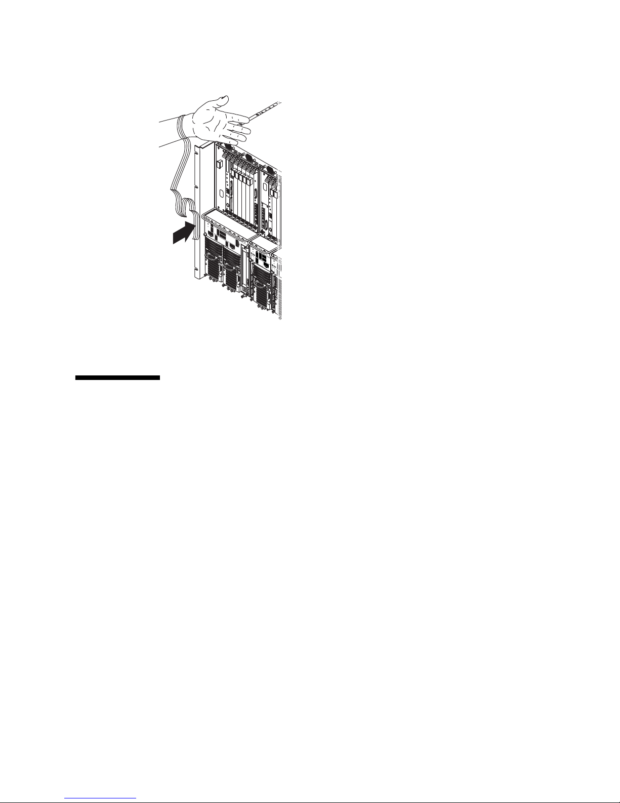
the chassis, as shown in
FIGURE 1-1.
1-2 Netra CT Server Service Manual • February 2007
Page 31
A
BORT
RESET
ALARM/USER
RE
A
D
Y
ET
H
ERN
ET
HDD1
mi
cr
o
sy
st
e
m
s
C
O
M
H
O
TS
W
A
P
H
D
D
0
ALARM
A
B
ORT
H
D
D
0
RESET
ALARM
/
USER
READ
Y
E
T
H
E
R
N
E
T
COM 2
m
COM 1 ENET 1 ENET 2
i
c
r
o
s
y
s
t
em
COM 2
s
H
OT
S
W
AP
COM 1 ENET 1 ENET 2
C
O
M
ALARM
H
O
T
SW
A
P
HO
T
SW
A
P
COM 2
COM 1 ENET 1 ENET 2
ALARM
H
O
T
S
W
A
P
FIGURE 1-1 Attaching the Antistatic Wrist Strap
1.3 FRU Categories
In general, the FRUs in a Netra CT server can be divided into two categories:
■ Hot-installable/replaceable (referred to hereafter as hot-swappable), meaning that
you can install or remove and replace the FRU while the server is running,
without interrupting the operation of the server. This category of FRU sometimes
requires that you enter hot-swap software commands before and after an
installation or a removal/replacement to incorporate the new FRU in the system
correctly. For information on hot-swap commands, see Chapter 5.
■ Non-hot-swappable, or cold-swappable, meaning that you must halt (and, in some
cases, also power off) the server before installing or removing and replacing a
FRU. Note that you must halt power only to the server where you would be
removing and replacing the FRUs; any other servers installed in the same chassis
can remain running.
Redundant power supplies and hard drives in a Netra CT 810 server are a variation
of the hot-swappable category. You can replace a single power supply in a
redundant configuration while the server is running, without having to enter any
software commands, or a single hard drive after you have unmounted the drive or
disengaged it if you are running a disk management software package.
Chapter 1 Preparing for FRU Installation and Replacement 1-3
Page 32

1.3.1 Hot-Swappable FRUs
The FRUs listed below are hot-swappable:
■ I/O boards
■ Satellite CPU boards and satellite RTMs
■ Alarm cards for both the Netra CT 810 server and the Netra CT 410 server
■ Alarm rear transition modules
■ Host CPU board
■ Host CPU rear transition module (rear-access model only)
■ Either of the two hard drives in a Netra CT 810 server
■ DVD or DAT (digital audio tape) drives occupying the removable media module
■ Fan trays
■ System status panels
■ System controller boards
■ Either of the two power supply units in a Netra CT 810 server
■ Power supply unit air filters
■ Main air filters
2
The instructions for removing and replacing these hot-swappable FRUs are covered
in Part 3.
1
3
1
2
1.3.2 Cold-Swappable FRUs
The FRUs listed below are cold-swappable:
■ Single power supply in a Netra CT 410 server
■ Single or lone remaining power supply in a Netra CT 810 server
■ Single hard drive in a Netra CT 410 server
■ Single or lone remaining hard drive in a Netra CT 810 server
■ Power distribution units
■ Powered-off or empty servers
The instructions for removing and replacing these cold-swappable FRUs are covered
in Part 4.
1. The alarm card andalarm reartransition module are hot-swappable only if thehost CPU board and system
controller board are alsoinstalled in the Netra CTserver.
2. The host CPUboard andthe host CPU rear transition modules are hot-swappableonly if the alarm card and
system controllerboard are alsoinstalled in the Netra CTserver.
3. The system controller board ishot-swappable only if the alarmcard andhost CPUboard areinstalled in the
Netra CTserver.
1-4 Netra CT Server Service Manual • February 2007
Page 33

1.4 Device Names
The following sections provide information about device names for I/O slots and
hard drives.
1.4.1 Device Names for I/O Board Slots in the Netra CT
Servers
TABLE 1-1 gives the device names for the I/O board slots in the Netra CT 810 server,
and
TABLE 1-2 gives the device names for the I/O board slots in the Netra CT 410
server.
TABLE 1-1 Device Names for I/O Board Slots in the Netra CT 810 Server
Slot Number Device Name
2 /devices/pci@1f,0/pci@1/pci@1/pci@f
3 /devices/pci@1f,0/pci@1/pci@1/pci@e
4 /devices/pci@1f,0/pci@1/pci@1/pci@d
5 /devices/pci@1f,0/pci@1/pci@1/pci@c
6 /devices/pci@1f,0/pci@1/pci@1/pci@b
7 /devices/pci@1f,0/pci@1/pci@1/pci@a
8 /devices/pci@1f,0/pci@1/pci@1/pci@8
TABLE 1-2 Device Names for I/O Board Slots in the Netra CT 410 Server
Slot Number Device Name
1 /devices/pci@1f,0/pci@1/pci@1/pci@8
2 /devices/pci@1f,0/pci@1/pci@1/pci@f
4 /devices/pci@1f,0/pci@1/pci@1/pci@e
5 /devices/pci@1f,0/pci@1/pci@1/pci@d
Note – For Netra CP2500 boards, pcia and pcib probe lists do not apply.
Chapter 1 Preparing for FRU Installation and Replacement 1-5
Page 34

1.4.2 Device Names for hard drives
Following are the device names for the hard drives installed in the Netra CT servers:
■ Netra CT 810 server:
■ HDD 0—c0t0d0
■ HDD 1—c1t1d0
■ Netra CT 410 server:
■ HDD 0—c0t0d0
1-6 Netra CT Server Service Manual • February 2007
Page 35

CHAPTER
2
Powering the Server Off and On
This chapter provides instructions on powering the Netra CT server on and off. This
chapter contains the following topics:
■ Section 2.1, “Powering On the Server” on page 2-2
■ Section 2.3, “Powering Off the Server” on page 2-7
Note – Whenever you reboot or power your server on and off, the hot-swap states
revert back to the default full hot-swap state for all I/O slots. If you want basic hotswap on an I/O slot, you must manually reset the I/O slot to basic hot-swap after
rebooting or powering your server on and off.
Note – You can also power the Netra CT server on and off through the alarm card
using the poweroff and poweron commands. Refer to the Netra CT Server System
Administration Guide for more information.
2-1
Page 36

2.1 Powering On the Server
Note – You must have the host CPU board, alarm card, and system controller board
installed in the Netra CT server before you can power it on; the server will not
power on properly unless these three are installed. Once the system is powered on
and running, then you can hot-swap any of the three components as documented in
this manual.
Note – Do not reboot the server if the alarm card is in the process of resetting.
The system power on sequence is as follows:
1. The alarm card comes up and powers on the power supplies
2. The alarm card powers on I/O boards
3. The alarm card powers on the host CPU board, and the Solaris OS boots
4. The alarm card powers on satellite CPU boards supported by Sun Microsystems,
such as the Netra CP2160 and the Netra CP2500.
The power on sequence must finish before you can use the alarm card CLI
commands poweron cpu_node and poweroff cpu_node.
2-2 Netra CT Server Service Manual • February 2007
Page 37
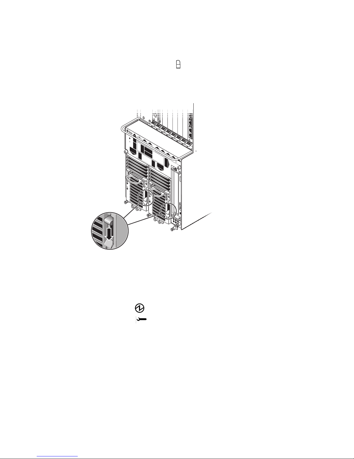
1. Verify that the power supply locking mechanisms on the server you are about to
power on are in the locked (), or down, positions.
FIGURE 2-1 shows the location of the power supply locking mechanisms on the Netra
CT server. Make sure you lock both power supplies if you are powering on a Netra
CT 810 server.
C
O
M
H
O
T
S
W
A
P
COM 1 ENET 1 ENET 2COM 2
H
O
T
S
W
A
P
FIGURE 2-1 Locating the Power Supply Locking Mechanism on the Netra CT 810 Server
When the power supply locking mechanism is locked, the green LEDs on the power
supplies flash, indicating that the power supplies are powered on, but the server has
not been powered on yet. Also, the power distribution unit (PDU) LEDs on the
system status panel should be in the following states:
Green LED ( ) is ON
Amber LED ( ) is OFF
This status tells you that the power supply locking mechanisms are in the locked
(down) position and the PDUs are receiving power and functioning properly.
Chapter 2 Powering the Server Off and On 2-3
Page 38
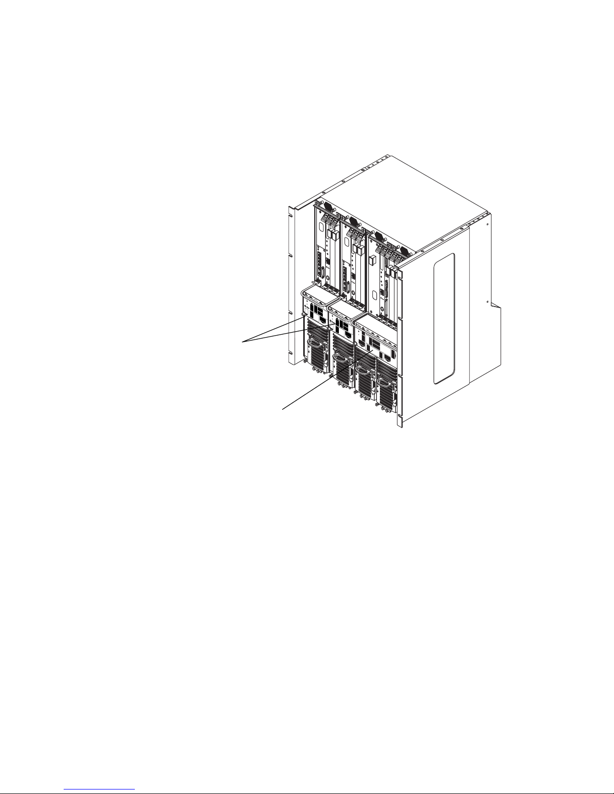
2. Locate the system status panel.
The locations of the system status panel in the Netra CT 810 server and Netra CT 410
server are illustrated in
FIGURE 2-2.
H
DD0
A
B
O
R
T
HDD0
R
E
S
E
T
A
L
A
R
M
/U
S
E
R
R
E
A
D
Y
A
B
O
R
T
E
T
H
E
R
N
R
E
E
T
S
E
T
A
L
A
R
M
/U
S
E
R
R
E
A
D
Y
m
i
c
r
o
s
y
s
t
e
m
COM 2
s
COM 1 ENET 1 ENET 2
C
O
M
ALARM
H
O
T
S
W
A
P
H
O
T
S
W
A
P
COM 2
COM 1 ENET 1 ENET 2
H
O
T
S
W
A
P
A
B
O
R
E
T
ALARM
H
O
T
T
H
E
R
N
E
T
R
E
S
E
T
A
L
A
R
M
/
U
S
E
m
C
O
S
W
R
R
i
c
r
E
o
s
y
A
s
t
e
m
D
s
Y
E
T
H
E
R
N
E
T
M
HDD1
A
P
m
i
c
r
o
s
y
s
t
e
m
s
C
O
M
H
O
T
S
W
A
P
ALARM
COM 2
COM 1 ENET 1 ENET 2
H
O
T
S
W
A
P
System status panels,
Netra CT 410 servers
System status panel,
Netra CT 810 server
FIGURE 2-2 System Status Panel Locations
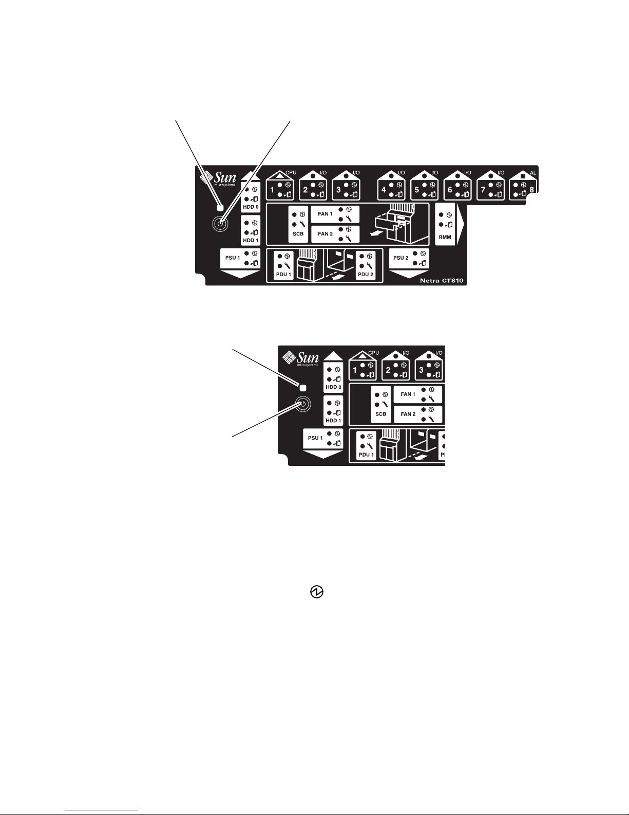
3. Locate the system power button on the system status panel, then press the system
power button to power on the server.
FIGURE 2-3 shows the system power button location for the Netra CT 810 server, and
FIGURE 2-4 shows the system power button location for the Netra CT 410 server.
2-4 Netra CT Server Service Manual • February 2007
Page 39
System power
LED
FIGURE 2-3 System Power Button and System Power LED Locations (Netra CT 810
System power
button
Server)
System power
LED
System power
button
FIGURE 2-4 System Power Button and System Power LED Locations (Netra CT 410
Server)
4. Verify that the system power LEDs on the system status panel is on, indicating
that the system is completely powered on.
FIGURE 2-3 shows the system power LED location for the Netra CT 810 server, and
FIGURE 2-4 shows the system power LED location for the Netra CT 410 server.
5. Verify that the green power ( ) LED on the power supplies are on, not blinking,
indicating that they are powered on and functioning properly.
6. Connect to the console and boot the server.
See Appendix B for instructions on connecting a terminal to your server, if necessary.
Chapter 2 Powering the Server Off and On 2-5
Page 40
2.2 Verifying Full Power-Up
The Netra CT server may take several minutes to completely power up and finish
the configuration process, depending on the number of I/O boards installed in the
system. Do not remove or install any boards in the Netra CT server until you have
verified that the system is completely powered up.
To verify that the system is completely powered up and is fully configured, as
superuser, enter:
# prtpicl -c fru -v | more
Output similar to the following is displayed:
chassis (fru, 3d00000008)
:ChassisType SUNW,NetraCT-810
:State configured
:_class fru
:name chassis
...
■ If the entry in the State field is configured, then the system is completely
powered up and configured. You can safely remove and install boards at this
point.
■ If the entry in the State field is not configured (for example, configuring or
unconfigured), then the system is still coming up. Do not remove or install any
boards in the Netra CT server in this state. You must wait until the state is
configured.
2-6 Netra CT Server Service Manual • February 2007
Page 41

2.3 Powering Off the Server
You can power off the Netra CT server in three ways:
■ Graceful hardware power-down
■ Ungraceful hardware power-down
■ Graceful software power-down
If you do not have a terminal hookup to your server and your CPU is functioning
normally, initiate a graceful hardware power-down for your server. For a graceful
hardware power-down, press the system power button for less than four seconds.
This will start the orderly power-down sequence in such a manner that no persistent
OS data structures are corrupted. In the orderly power-down, applications in service
are terminated and no further services are invoked by the CPU.
If you do not have a terminal hookup to your server and your CPU is not
functioning normally, you cannot initiate a graceful hardware power-down; you
must perform an ungraceful hardware power-down. For an ungraceful hardware
power-down, press the system power button for more than four seconds. This
immediately shuts the system down without making any attempts to keep the
persistent OS data structures from being corrupted.
A graceful software power-down is a normal power-down using a terminal
connected to your server, where you log onto the server as superuser, then execute a
software command to bring the server down safely.
■ For hardware power-down instructions, go to Section 2.3.1, “To Perform a
Hardware Power-Down” on page 2-7.
■ For software power-down instructions, go to Section 2.3.2, “To Perform a
Software Power Down” on page 2-8.
2.3.1 To Perform a Hardware Power-Down
1. In preparation for bringing down the operating system and powering off the
server, ensure that all significant application activity is stopped on the server.
2. Go to the front of the Netra CT server and locate the system status panel.
The locations of the system status panels in the Netra CT 810 server and Netra CT
410 server are illustrated in
3. Locate the system power button on the system status panel.
FIGURE 2-3 shows the system power button location for the Netra CT 810 server, and
FIGURE 2-4 shows the system power button location for the Netra CT 410 server.
FIGURE 2-2.
Chapter 2 Powering the Server Off and On 2-7
Page 42
4. Press the system power button and release it to go through a graceful hardware
power-down.
This action starts the orderly power-down sequence in such a manner that no
persistent OS data structures are corrupted. Applications in service might be
terminated and no further services are invoked by the CPU. The system power LED
blinks for several seconds, then it goes off.
5. Verify that the green power ( ) LEDs on the power supplies are blinking,
indicating that the system is in the standby mode.
FIGURE 2-3 shows the system power LED location for the Netra CT 810 server, and
FIGURE 2-4 shows the system power LED location for the Netra CT 410 server.
6. If you want to completely power off the Netra CT server, push the purple power
supply unit locking mechanisms up into the unlocked ()position (
FIGURE 2-1).
Note – You must unlock the locking mechanism on both power supply units on the
Netra CT 810 server in order to completely power off that server.
The green power ( ) LEDs on the power supply units should go off (unlit),
indicating that the system is now completely powered off.
2.3.2 To Perform a Software Power Down
1. In preparation for bringing down the operating system and powering down the
server, ensure that all significant application activity is stopped on the server.
2. Log in as superuser at the system console and enter:
# cd /
# shutdown -i0 -g0 -y
When the server is finished shutting down, the ok prompt is displayed.
3. Connect to the console and boot up the server.
See Appendix B for instructions on connecting a terminal to your server, if necessary.
4. At the ok prompt, enter:
ok power-off
2-8 Netra CT Server Service Manual • February 2007
Page 43
5. Go to the front of the Netra CT server and locate the system status panel (see
FIGURE 2-2).
The locations of the system status panel in the Netra CT 810 server and Netra CT 410
server are illustrated in
FIGURE 2-2.
6. Verify that the green power ( ) LEDs on the power supplies are blinking,
indicating that the system is in the standby mode.
FIGURE 2-3 shows the system power LED location for the Netra CT 810 server, and
FIGURE 2-4 shows the system power LED location for the Netra CT 410 server.
7. If you want to completely power off the Netra CT server, push the purple power
supply unit locking mechanisms up into the unlocked ()position (
FIGURE 2-1).
Note – You must unlock the locking mechanism on both power supply units on the
Netra CT 810 server to completely power off the server.
The green power ( ) LEDs on the power supply units turn off (unlit), indicating
that the system is now completely powered off.
Chapter 2 Powering the Server Off and On 2-9
Page 44

2-10 Netra CT Server Service Manual • February 2007
Page 45

CHAPTER
3
Handling Boards and Assemblies
This chapter gives instructions on how to safely handle the CompactPCI boards and
assemblies. This chapter is divided into the following sections:
■ Section 3.1, “Handling Boards” on page 3-2
■ Section 3.2, “Handling Assemblies” on page 3-3
Consult the Netra CT Server Safety and Compliance Manual for safety information prior
to performing the procedures in this chapter.
3-1
Page 46
3.1 Handling Boards
Each Netra CT server in a chassis has a CompactPCI bus. All of the boards in a
server—the CPU board, alarm card, and I/O boards—are CompactPCI boards.
Caution – The system is sensitive to static electricity. To prevent damage, always
connect an antistatic wrist strap between you and the system.
Caution – Do not flex the CompactPCI boards; the surface-mounted components
can break.
To minimize the amount of flexing, observe the following precautions:
■ When removing a board from an electrostatic discharge bag, keep it vertical until
you lay it on the electrostatic discharge mat.
■ Do not place a board on a hard surface. Use a cushioned antistatic mat. The
connectors and components have very thin pins that bend easily.
■ Be careful of small parts located on the component side of a board.
■ Do not use an oscilloscope probe on the components. The soldered pins are easily
damaged or shorted by the probe point.
■ Transport a board in an antistatic bag.
Caution – The heat sinks on a board can be damaged by incorrect handling. Do not
touch the heat sinks while installing or removing a board. Hold a board only by the
edges. If a heat sink is loose or broken, obtain a replacement board.
Caution – The heat sinks on a board can be damaged by improper packaging.
When storing or shipping a board, ensure that the heat sinks have sufficient
protection.
Caution – The system controller board and its modules have surface-mount
components that can be broken by flexing the board.
3-2 Netra CT Server Service Manual • February 2007
Page 47
3.2 Handling Assemblies
Assemblies have their own set of handling requirements, similar to the requirements
for CompactPCI boards.
Caution – The system is sensitive to static electricity. To prevent damage to the
board, always connect an antistatic wrist strap between you and the system.
Chapter 3 Handling Boards and Assemblies 3-3
Page 48

3-4 Netra CT Server Service Manual • February 2007
Page 49

PA R T
2 Troubleshooting the System
Troubleshooting the System Chapter 4
Page 50

Page 51

CHAPTER
4
Troubleshooting the System
This chapter provides instructions for troubleshooting the Netra CT server. You can
troubleshoot the system several ways.
■ Section 4.1, “Troubleshooting the System Using the System Status Panel” on
page 4-2
■ Section 4.2, “Troubleshooting the System Using prtdiag” on page 4-9
■ Section 4.3, “Troubleshooting the System Using Diagnostic Software” on
page 4-14
■ Section 4.4, “Troubleshooting the System Using the Power-On Self Test (POST)”
on page 4-16
■ Section 4.5, “Troubleshooting the System Using the Alarm Card Software” on
page 4-18
■ Section 4.6, “Troubleshooting a Power Supply Using the Power Supply Unit
LEDs” on page 4-18
■ Section 4.7, “Troubleshooting a Host CPU Board” on page 4-20
In addition, Appendix C lists the error messages that might appear when you are
operating or servicing a Netra CT server.
4-1
Page 52
4.1 Troubleshooting the System Using the
System Status Panel
You can use the system status panel to troubleshoot the Netra CT server.
4.1.1 Locating and Understanding the System Status
Panel
The system status panel on the Netra CT server give the majority of troubleshooting
information that you need for your server.
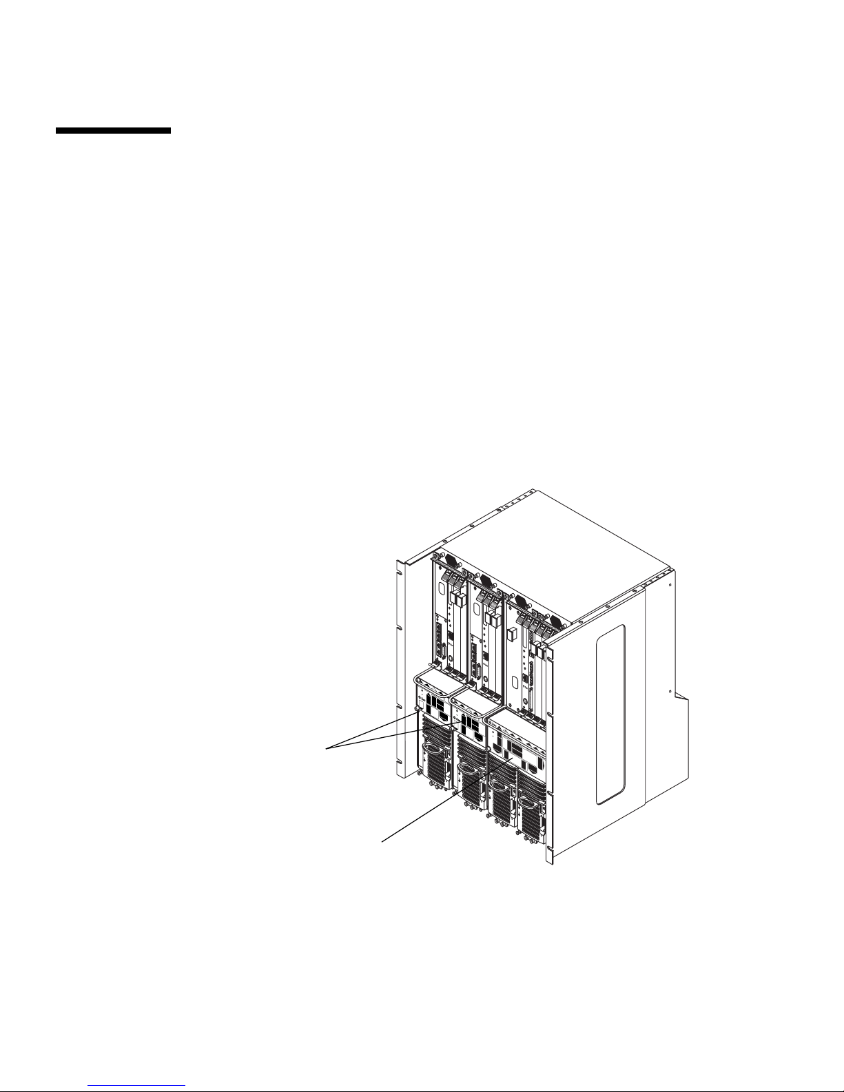
system status panels on the Netra CT servers.
panel for the Netra CT 810 server, and
the Netra CT 410 server.
FIGURE 4-1 shows the locations of the
FIGURE 4-2 shows the system status
FIGURE 4-3 shows the system status panel for
System status panels,
Netra CT 410 servers
System status panel,
Netra CT 810 server
FIGURE 4-1 System Status Panel Locations
HD
D0
A
B
O
R
T
HDD0
R
E
S
E
T
A
L
A
R
M
/
U
S
E
R
R
E
A
D
Y
A
B
O
R
T
E
T
H
E
R
N
R
E
E
T
S
E
T
A
L
A
R
M
/
U
S
E
R
R
E
A
D
Y
m
i
c
r
o
s
y
s
t
e
m
COM 2
s
COM 1 ENET 1 ENET 2
C
O
M
ALARM
H
O
T
S
W
A
P
H
O
T
S
W
A
P
COM 2
COM 1 ENET 1 ENET 2
H
O
T
S
W
A
P
A
B
O
R
E
T
ALARM
H
O
T
T
H
E
R
N
E
T
R
E
S
E
T
A
L
A
R
M
/U
S
E
m
C
O
S
W
R
R
i
c
r
E
o
s
y
A
s
t
e
m
D
s
Y
E
T
H
E
R
N
E
T
M
HDD1
A
P
m
i
c
r
o
s
y
s
t
e
m
s
C
O
M
H
O
T
S
W
A
P
ALARM
COM 2
COM 1 ENET 1 ENET 2
H
O
T
S
W
A
P
4-2 Netra CT Server Service Manual • February 2007
Page 53
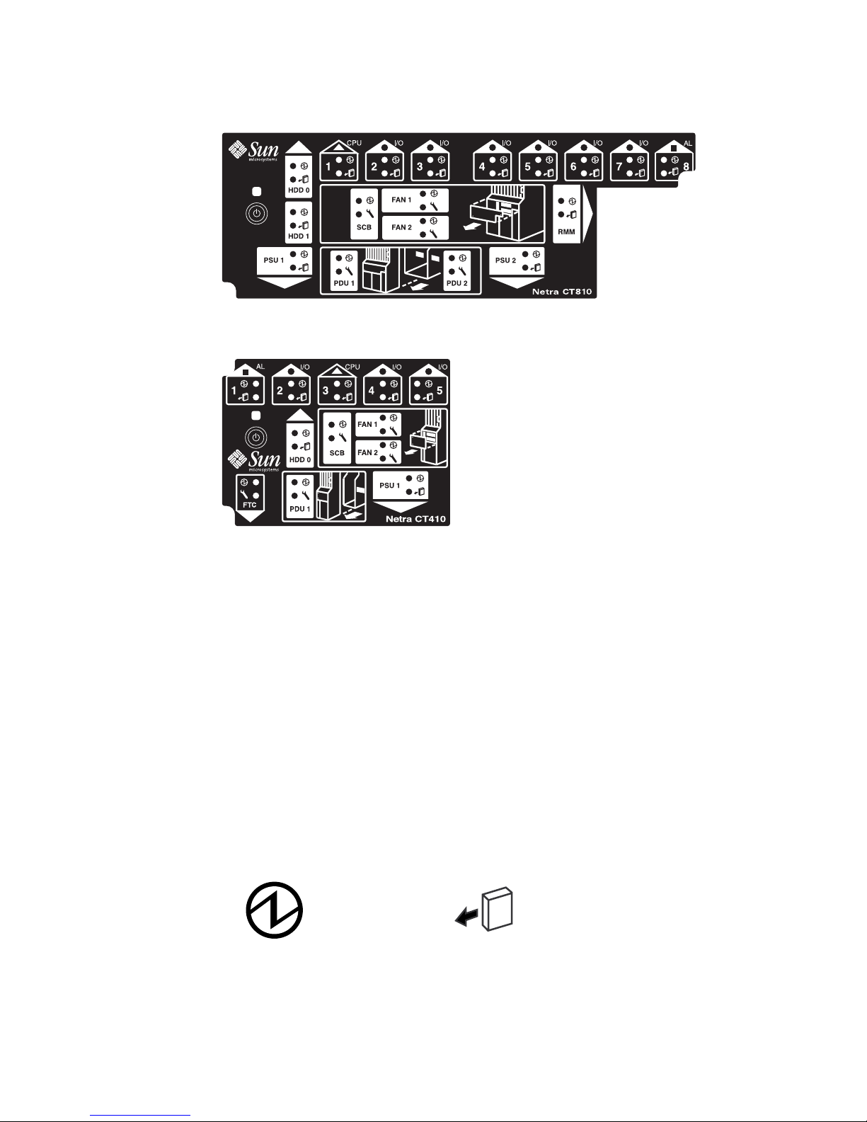
FIGURE 4-2 System Status Panel (Netra CT 810 Server)
FIGURE 4-3 System Status Panel (Netra CT 410 Server)
4.1.2 Using the System Status Panel LEDs to
Troubleshoot the System
When you first power-on the Netra CT server, some or all of the green Power LEDs
on the system status panel flash on and off for several seconds. Do not attempt to
troubleshoot the system until after the LEDs have gone through their initial poweron testing.
Each major component in the Netra CT 810 server and Netra CT 410 server has a set
of LEDs on the system status panel that gives the status on that component. Each
component has either green Power and amber Okay to Remove LEDs (
green Power and amber Fault LEDs (
Green Power LED
FIGURE 4-4 Power and Okay to Remove LEDs
FIGURE 4-4)or
FIGURE 4-5).
Amber Okay to Remove LED
Chapter 4 Troubleshooting the System 4-3
Page 54
Green Power LED
FIGURE 4-5 Power and Fault LEDs
TABLE 4-1 lists the LEDs for each component in the Netra CT 810 server, and
TABLE 4-2 lists the LEDs for each component in the Netra CT 410 server. Note that the
Amber Fault LED
boards in the Netra CT servers all have the green Power LED, and they have either
the amber Okay to Remove LED or the amber Fault LED, not both.
TABLE 4-1 System Status Panel LEDs for the Netra CT 810 Server
LED LEDs Available Component
HDD 0 Power and Okay to
Upper hard drive
Remove
HDD 1 Power and Okay to
Lower hard drive
Remove
Slot 1 Power and Okay to
Host CPU board installed in slot 1
Remove
Slots 2 - 7 Power and Okay to
I/O board or satellite CPU board (
●) installed in slot 2 - 7
Remove
Slot 8 Power and Okay to
Alarm card (
■) installed in slot 8
Remove
SCB Power and Fault System controller board (behind the system status panel)
FAN 1 Power and Fault Upper fan tray (behind the system status panel)
FAN 2 Power and Fault Lower fan tray (behind the system status panel)
RMM Power and Okay to
Removable media module
Remove
PDU 1 (DC only) Power and Fault Left most power distribution unit (behind the server)
PDU 2 (DC only) Power and Fault Right most power distribution unit (behind the server)
PSU 1 Power and Okay to
Left most power supply unit
Remove
PSU 2 Power and Okay to
Remove
4-4 Netra CT Server Service Manual • February 2007
Right most power supply unit
Page 55

TABLE 4-2 System Status Panel LEDs for the Netra CT 410 Server
LED LEDs Available Component
Slot 1 Power and Okay to
Alarm card(■) installed in slot 1
Remove
Slot 2 Power and Okay to
I/O board or satellite CPU board (
●) installed in slot 2
Remove
Slot 3 Power and Okay to
Host CPU board installed in slot 3
Remove
Slot 4 and 5 Power and Okay to
Remove
HDD 0 Power and Okay to
I/O boards or satellite CPU boards (
5
hard drive
●) installed in slot 4 and
Remove
SCB Power and Fault System controller board (behind the system status panel)
FAN 1 Power and Fault Upper fan tray (behind the system status panel)
FAN 2 Power and Fault Lower fan tray (behind the system status panel)
PDU 1 (DC only) Power and Fault Power distribution unit (behind the server)
PSU 1 Power and Okay to
Power supply
Remove
■ TABLE 4-3 lists the LED states and meanings for any CompactPCI board installed
in a slot in the Netra CT 810 server or Netra CT 410 server.
■ TABLE 4-4 lists the LED states and meanings for any component other than a
CompactPCI board that has the green Power and amber Okay to Remove LEDs.
■ TABLE 4-5 lists the LED states and meanings for any component other than a
CompactPCI board that has the green Power and amber Fault LEDs.
Note – Do not use the information in TABLE 4-4 to troubleshoot a power supply unit
in a server that has only one power supply unit (a Netra CT 410 server or a Netra CT
810 server with only one power supply). To troubleshoot the power supply in a
single power supply system, use the LEDs on the power supply itself. See
Section 4.6, “Troubleshooting a Power Supply Using the Power Supply Unit LEDs”
on page 4-18 for more information. The information given in
TABLE 4-4 applies to all
other components in the Netra CT 810 server or Netra CT 410 server, including the
power supplies in a two-power supply Netra CT 810 server.
Chapter 4 Troubleshooting the System 4-5
Page 56

Green
Power
LED state
TABLE 4-3 CompactPCI Board LED States and Meanings
Amber
Okay to
Remove
LED state Meaning Action
Off Off The slot is empty or the system
thinks that the slot is empty
because the system didn’t detect
the component when it was
inserted.
Blinking Off The component is coming up or
going down.
On Off The component is up and
running.
If there is a component installed in this slot, then
one of the following boards is faulty:
• the board installed in the slot
• the alarm card
• the system controller board
Remove and replace the failed board to clear this
state.
Do not remove the component in this state.
Do not remove the component in this state.
4-6 Netra CT Server Service Manual • February 2007
Page 57
TABLE 4-3 CompactPCI Board LED States and Meanings
Amber
Green
Power
LED state
Okay to
Remove
LED state Meaning Action
Off On The component is powered off. You can remove the component in this state.
Blinking
or Off
On The component is powered on,
but it is offline for some reason
(for example, a fault was
detected on the component).
On On The component is powered on
and is in use, but a fault has
been detected on the component
Wait until the green Power LED stops blinking. If it
does not stop blinking after several seconds, enter
cfgadm and verify that the component is in the
unconfigured state, then perform the necessary
action, depending on the component:
• Alarm card—When the green Power LED is OFF
and the amber
Okay to Remove LED is ON,
you can remove the alarm card.
• All other boards—Power off the slot through the
alarm card software, then remove the
component.
Deactivate the component using one of the
following methods:
• Use the cfgadm -f -c unconfigure
command to deactivate the component. Note that
in some cases, this may cause the system to
panic, depending on the nature of the
component’s hardware or software.
• Halt the system and power off the slot through
the alarm card software, then remove the
component.
The green Power LED will then give status
information:
• If the green Power LED goes off, then you can
remove the component.
• If the green Power LED remains on, then you
must halt the system and power off the slot
through the alarm card software.
TABLE 4-4 Meanings of Power and Okay to Remove LEDs
LED State Power LED Okay to Remove LED
On, Solid
Component is installed and
configured.
Component is Okay to Remove. You
can remove the component from the
system, if necessary.
Chapter 4 Troubleshooting the System 4-7
Page 58
TABLE 4-4 Meanings of Power and Okay to Remove LEDs
LED State Power LED Okay to Remove LED
On, Flashing
Component is installed but is
Not applicable.
unconfigured or is going through the
configuration process.
Off
TABLE 4-5 Meanings of Power and Fault LEDs
LED State Power LED Fault LED
On, Solid
On, Flashing
Component was not recognized by
the system or is not installed in the
slot.
Component is installed and
configured.
Component is installed but is
Component is not Okay to Remove.
Do not remove the component while
the system is running.
Component has failed. Replace the
component.
Not applicable.
unconfigured or is going through the
configuration process.
Off
Component was not recognized by
Component is functioning properly.
the system or is not installed in the
slot.
4-8 Netra CT Server Service Manual • February 2007
Page 59

4.2 Troubleshooting the System Using
prtdiag
You can troubleshoot the system using the prtdiag command. Log onto the server
console and, as root, enter:
# /usr/platform/sun4u/sbin/prtdiag
If you have a Netra CT 810 server, the output on the console is similar to the
following:
CODE EXAMPLE 4-1 prtdiag Output for a Netra CT 810 Server
System Configuration: Sun Microsystems sun4u SPARCengine CP2000 model 140
(UltraSPARC-IIi 648MHz)
Memory size: 512 Megabytes
platform is : SUNW,NetraCT-810
=============================== FRU Information ===============================
FRU FRU FRU Green Amber Miscellaneous
Type Unit# Present LED LED Information
---------- ----- ------- ----- ----- -------------------------Midplane 1 Yes Netra ct800
Properties:
Version=0
Maximum Slots=8
SCB 1 Yes on off System Controller Board
Properties:
Version=2
hotswap-mode=basic
SSB 1 Yes System Status Panel
CPU 1 Yes on off CPU board
temperature(celsius):38
I/O 2 Yes on off CompactPCI IO Slot
Properties:
auto-config=disabled
Board Type:Unknown
Devices:
pci
pci108e,1000
SUNW,hme
SUNW,isptwo
I/O 3 Yes on off CompactPCI IO Slot
Properties:
auto-config=disabled
Chapter 4 Troubleshooting the System 4-9
Page 60

CODE EXAMPLE 4-1 prtdiag Output for a Netra CT 810 Server (Continued)
Board Type:Unknown
Devices:
pci
pci108e,1000
SUNW,hme
SUNW,isptwo
I/O 4 Yes on off CompactPCI IO Slot
Properties:
auto-config=disabled
Board Type:Unknown
Devices:
pci
pci108e,1000
SUNW,hme
SUNW,isptwo
I/O 5 Yes on off CompactPCI IO Slot
Properties:
auto-config=disabled
Board Type:Unknown
Devices:
pci
pci108e,1000
SUNW,hme
SUNW,isptwo
I/O 6 Yes on off CompactPCI IO Slot
Properties:
auto-config=disabled
I/O 7 Yes on off CompactPCI IO Slot
Properties:
auto-config=disabled
Board Type:Unknown
Devices:
pci
pci108e,1000
SUNW,qfe
pci108e,1000
SUNW,qfe
pci108e,1000
SUNW,qfe
pci108e,1000
SUNW,qfe
pci1176,608
I/O 8 Yes on off CompactPCI IO Slot
Properties:
auto-config=disabled
Board Type:Alarm Card
Devices:
4-10 Netra CT Server Service Manual • February 2007
Page 61

CODE EXAMPLE 4-1 prtdiag Output for a Netra CT 810 Server (Continued)
pci
ebus
ethernet
PDU 1 Yes on off Power Distribution Unit
PDU 2 Yes on off Power Distribution Unit
PSU 1 Yes on on Power Supply Unit
condition:ok
temperature:ok
ps fan:ok
supply:on
PSU 2 Yes on on Power Supply Unit
condition:ok
temperature:ok
ps fan:ok
supply:on
FAN 1 Yes on off Fan Tray
condition:ok
fan speed:low
FAN 2 Yes on off Fan Tray
condition:ok
fan speed:low
HDD 0 Yes on off hard drive
condition:ok
HDD 1 Yes on off hard drive
condition:ok
RMM Yes on on Removable Media Module
condition:Unknown
System Board PROM revision:
--------------------------OBP 3.14.1 2000/04/28 12:56
Chapter 4 Troubleshooting the System 4-11
Page 62

If you have a Netra CT 410 server, the output on the console is similar to the
following:
CODE EXAMPLE 4-2 prtdiag Output for a Netra CT 410 Server
System Configuration: Sun Microsystems sun4u SPARCengine CP2000 model 140
(UltraSPARC-IIi 648MHz)
Memory size: 512 Megabytes
platform is : SUNW,NetraCT-410
=============================== FRU Information ===============================
FRU FRU FRU Green Amber Miscellaneous
Type Unit# Present LED LED Information
---------- ----- ------- ----- ----- -------------------------Midplane 1 Yes Netra ct400
Properties:
Version=0
Maximum Slots=5
SCB 1 Yes on off System Controller Board
Properties:
Version=2
hotswap-mode=basic
SSB 1 Yes System Status Panel
I/O 1 Yes on off CompactPCI IO Slot
Properties:
auto-config=disabled
Board Type:Alarm Card
Devices:
pci
ebus
ethernet
I/O 2 Yes off off CompactPCI IO Slot
Properties:
auto-config=disabled
CPU 3 Yes on off CPU board
temperature(celsius):38
I/O 4 Yes on off CompactPCI IO Slot
Properties:
auto-config=disabled
Board Type:Unknown
Devices:
pci
pci108e,1000
SUNW,hme
SUNW,isptwo
I/O 5 Yes on off CompactPCI IO Slot
Properties:
auto-config=disabled
Board Type:Unknown
Devices:
4-12 Netra CT Server Service Manual • February 2007
Page 63

CODE EXAMPLE 4-2 prtdiag Output for a Netra CT 410 Server (Continued)
pci
pci108e,1000
SUNW,qfe
pci108e,1000
SUNW,qfe
pci108e,1000
SUNW,qfe
pci108e,1000
SUNW,qfe
PDU 1 Yes on off Power Distribution Unit
PSU 1 Yes on off Power Supply Unit
condition:ok
temperature:ok
ps fan:ok
supply:on
FAN 1 Yes on off Fan Tray
condition:ok
fan speed:low
FAN 2 Yes on off Fan Tray
condition:ok
fan speed:low
HDD 0 Yes on off hard drive
condition:ok
System Board PROM revision:
--------------------------OBP 3.14.1 2000/04/28 12:56
Chapter 4 Troubleshooting the System 4-13
Page 64
4.3 Troubleshooting the System Using
Diagnostic Software
Software packages, such as Sun VTS, allow you to run diagnostic tests on your
system. SunVTS is a validation test suite that is provided as a supplement to the
Solaris operating environment. The individual tests can stress a device, system, or
resource so as to detect and pinpoint hardware and software failures and to provide
users with informational messages for resolving problems. SunVTS runs at the
operating system level.
The following tests are useful when troubleshooting a Netra CT server:
■ alarm2test—is part of SunVTS, but it is used to test the alarm card installed in
the Netra CT server by invoking the alarmdiag test on the alarm card.
alarm2test runs at the operating system level.
■ obdiag—is similar to the alarm2test, in that it invokes the alarmdiag test on
the alarm card; however, obdiag is run from the firmware level, not the
operating system level.
■ Apost—is part of the embedded firmware image on the alarm card. It runs a
basic test on the alarm card to verify that the alarm card is operating properly
before bringing up Chorus on the alarm card.
A new utility called diagconf, which is part of the embedded firmware image on
the alarm card, is now available. You can use diagconf to set or display the
configuration settings for Apost, allowing you to make the tests run on the alarm
card more or less thoroughly before the embedded firmware is brought up on the
alarm card.
To display the values currently set for Apost, access the alarm card command line
interface (CLI) and enter the following command:
hostname cli> diagconf -d
4-14 Netra CT Server Service Manual • February 2007
Page 65
Output similar to the following is displayed, giving you the values currently set for
the Apost test on the alarm card:
diag-switch False
verb-mode True
stop-on-error False
diag-level Max
mfg-mode Off
hdr-checksum 0xaa
time-stamp 0
record-format-ver 49
post-version 02
reset-status 0xd0000000
post-status ...
post-msg Watchdog Reset-------- POST Passed-------------------
Some values are hard-set and cannot be changed by a user, while others can be
changed to make the test more or less thorough. To change the value for a test, enter
the following command:
hostname cli> diagconf -s command value
where command is the name of the command that you want to change, and value is
the value you want to change.
The following table lists the Apost tests that can be changed by a user and the
allowable values for each. Any tests not listed in
TABLE 4-6 are either hard-set and
cannot be changed, or should not be changed by a user.
TABLE 4-6 Apost Tests and Values through diagconf
Command Value
diag-switch • True—Turns the diag-switch test on.
• False—Turns the diag-switch test off.
verb-mode • True—Turns the verb-mode test on.
• False—Turns the verb-mode test off.
stop-on-error • True—Stops the Apost testing when the first error is encountered.
• False—Continues Apost testing, regardless of the number of
errors encountered.
diag-level • Off—Turns the diag-level test off.
• Min—Sets the diag-level test to the minimum level of testing.
• Max—Sets the diag-level test to the maximum level of testing.
Chapter 4 Troubleshooting the System 4-15
Page 66
For more information on these and other tests in the SunVTS test suite, refer to the
Computer Systems Release Notes Supplement for Sun Hardware document or the
SunVTS documentation on the Solaris on Sun Hardware Answerbook, both included
with your Solaris operating environment.
4.4 Troubleshooting the System Using the
Power-On Self Test (POST)
When you first power-up the Netra CT server, some or all of the green Power LEDs
on the system status panel flash on and off for several seconds. The green Power
LED for the I/O slot holding the host board (slot 1 in the Netra CT 810 server and
slot 3 in the Netra CT 410 server) lights solid green while the green Power LEDs for
the remaining components are flashing on and off; this status is an indication that
the CPU board passed the power-on self test (POST).
Before any processing occurs on a system, the system must successfully complete the
POST. Messages are displayed for each step in the POST process. If there is a critical
failure, the system does not complete POST and does not boot. To monitor this
process, you must be connected to the TTY A port on the CPU board or rear
transition module. See Section 5.2.1, “Logging In to the Netra CT Server” on
page 5-5.
OpenBoot PROM (OBP) variables control the console port. The variables and their
possible settings are described as follows.
To see the console output device, enter:
ok printenv output-device
The screen displays output similar to the following:
output-device ttya
The possible settings for this variable are as follows:
■ ttya (default)
■ ttyb
■ screen
■ rsc
4-16 Netra CT Server Service Manual • February 2007
Page 67
Both ttya and ttyb represent the serial ports on the CPU board. screen represents
the display attached to the first frame buffer installed in the system (not present on
the Netra CT server). rsc is used by the alarm card.
To see the console input device, enter:
ok printenv input-device
The screen displays output similar to the following:
input-device ttya
The possible settings for this variable are:
■ ttya (default)
■ ttyb
■ keyboard
■ rsc
ttya and ttyb represent the serial ports on the CPU board. keyboard represents
the standard system keyboard (not present on the Netra CT server). rsc is used by
the alarm card. If no system keyboard is connected, the console port defaults to
ttya.
Note – Be sure the two variables are consistent with each other. For example, do not
set the output-device to screen and the input-device to ttya.
Another OBP variable controls the behavior of the POST process called diag-
level. By default, this variable is set to max, which means POST runs more
thorough (verbose) tests against the hardware. This variable can be set to min, which
runs a less stringent set of tests against the hardware. A minimum level of POST
testing takes less time, so the Solaris operating environment can boot more quickly
on a machine with diag-level set to min.
To run the maximum amount of POST tests, enter:
ok setenv diag-level max
To run the minimum amount of POST tests, enter:
ok setenv diag-level min
Chapter 4 Troubleshooting the System 4-17
Page 68
4.5 Troubleshooting the System Using the
Alarm Card Software
For information on troubleshooting using the alarm card software, refer to the Netra
CT Server System Administration Guide (819-2743-xx).
4.6 Troubleshooting a Power Supply Using
the Power Supply Unit LEDs
Two LEDs are on each power supply unit: a green ( ) LED and an amber ( )
LED. Use the LEDs on the power supply unit to troubleshoot each power supply
unit. Because there is one power supply unit in the Netra CT 410 server and two
power supply units in the Netra CT 810 server, the actions to take are different. The
following sections provide guidelines for each server.
4.6.1 Troubleshooting the Power Supply Unit in the
Netra CT 410 Server
Following are the states of the LEDs on the power supply unit in the Netra CT 410
server:
■ Green, flashing—The power supply unit is in the standby mode; the power
supply unit is powered on, yet it is not supplying power to the server.
■ Green, solid—Both the server and the power supply unit are powered on and
functioning properly.
■ Amber—A fault was found in the power supply unit. Replace the power supply
unit. See Section 10.2, “Cold-Swappable Power Supply Unit” on page 10-5 for
those instructions.
■ Off—One of the following conditions apply:
■ The power supply locking mechanism is in the upper, unlocked position.
■ The accompanying cable is disconnected from the power distribution unit.
■ The accompanying power distribution unit failed.
■ The power supply unit failed.
4-18 Netra CT Server Service Manual • February 2007
Page 69

4.6.2 Troubleshooting the Power Supply Units in the
Netra CT 810 Server
When both power supply units in a Netra CT 810 server are up and running
properly, the green ( )LEDs on both power supply units is ON (note that these are
the LEDs on the power supply units themselves, not the LEDs on the system status
panel).
If a power supply unit fails, the amber ( ) LED on the power supply unit might
light, depending on the type of failure that occurs:
■ If a soft-fault occurs, such as a stuck fan or a temperature warning, a notification
of the error is given; however, the amber ( ) LED on the power supply unit
does not light for a soft-fault condition. The power supply unit is still supplying
power to the system during a soft-fault condition.
■ If a hard-fault occurs, such as a voltage problem, a notification of the error is
given. In addition, the amber ( ) LED on the power supply unit does light for a
hard-fault condition. The power supply unit does not supply power to the system
during a hard-fault condition.
If one power supply unit fails (either a soft-fault or a hard-fault), but the other
power supply unit is still functioning normally, replace the faulty power supply unit
as soon as possible. If both power supply units fail, the action to take varies
depending on which of the two types of faults occurred:
If Then
Both power supply units go through a soft-fault Replace one power supply unit at a time, in
order to keep the system up and running.
One power supply unit goes through a soft-fault
and the other power supply unit goes through
a hard-fault
Both power supply units go through a hard-fault The system is down. Replace at least one of
Replace the power supply unit that has a
hard-fault first, in order to keep the system
up and running.
the power supply units to bring the system
back up again.
Chapter 4 Troubleshooting the System 4-19
Page 70
4.7 Troubleshooting a Host CPU Board
This section describes how to troubleshoot problems related to the host board. The
information provided here primarily covers situations when the system containing
the host board does not boot up or when the board is not fully functional after boot.
Only general troubleshooting tips are provided here. No component-level
troubleshooting information is included in this section.
The following topics are covered:
■ General troubleshooting tips
■ General troubleshooting requirements
■ Mechanical failures
■ Power-on failures
■ Failures subsequent to power-on
■ Troubleshooting during POST/OBP and during boot process
Also, the following diagnostic procedures are described:
■ OpenBoot PROM on-board diagnostics
■ OpenBoot diagnostics
4.7.1 General Troubleshooting Tips
Caution – High voltages are present in the Netra CT server. To avoid physical
injury, follow all the safety rules specified in the Netra CT Server Safety and
Compliance Manual when opening the enclosure and/or removing and installing a
board.
The following general troubleshooting tips are useful in isolating issues related to a
host board:
1. Make sure the host board is installed properly in the correct slot in the Netra CT
server.
The CPU board is installed in slot 1 in the Netra CT 810 server and in slot 3 in the
Netra CT 410 server.
4-20 Netra CT Server Service Manual • February 2007
Page 71
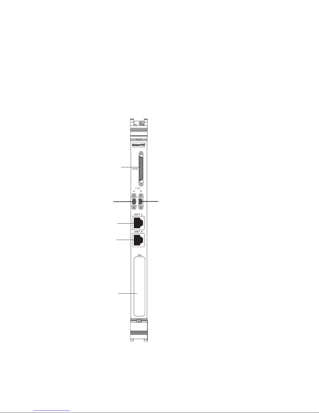
2. Make sure all the necessary cables are attached properly to the host rear transition
module.
The following are possible board and rear transition module combinations:
■ Netra CP2140 and Netra CT CPU transition card (CTC, hereafter referred to as
rear transition module)
■ Netra CP2500 and Netra CP2500 RTM-H (rear transition module for host)
FIGURE 4-6 shows the connectors on the CTC. FIGURE 4-7 shows connectors on the
RTM-H.
SCSI connector
TTY A
serial port
Ethernet
channel A
Ethernet
channel B
Cutout for
PIM connector
TTY B
serial port
FIGURE 4-6 Connectors on the Netra CP2140 Host Rear Transition Module
Chapter 4 Troubleshooting the System 4-21
Page 72
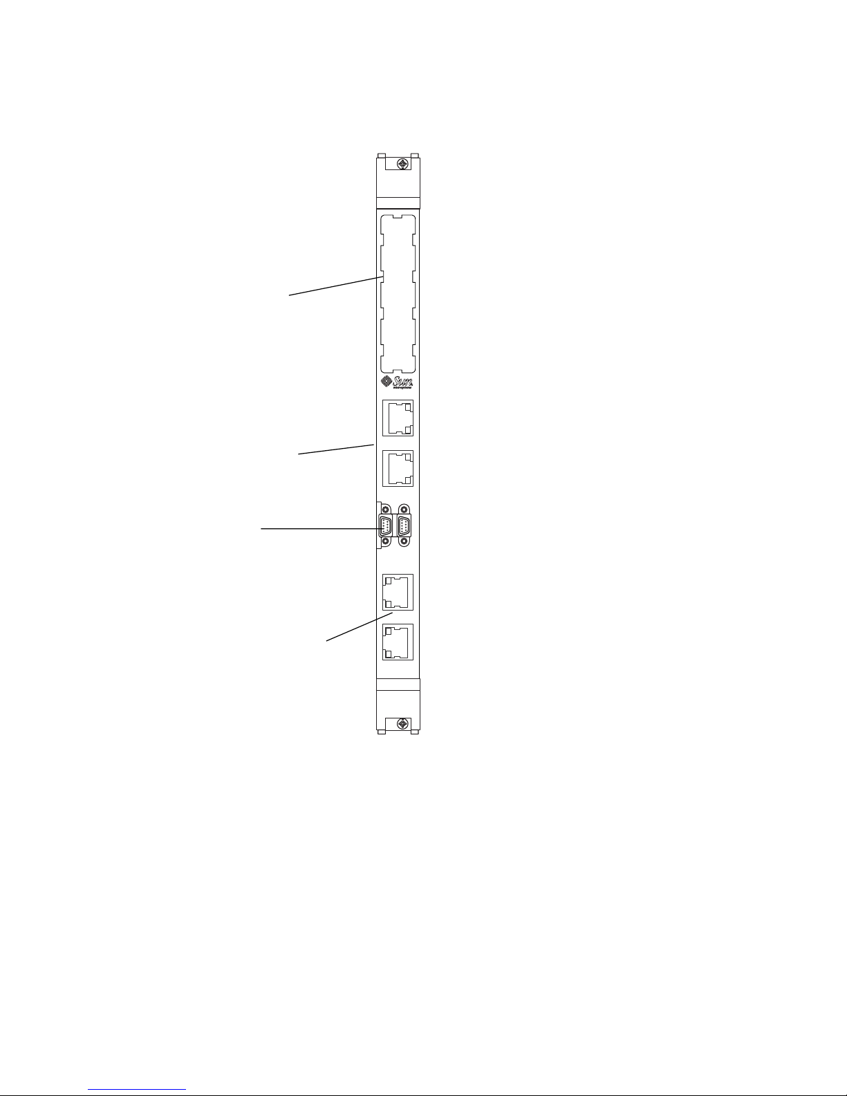
Cut out for
PIM connector
ENET 1
10/100/1000 Ethernet
RJ45 connectors
ENET 0
COM
AB
Serial ports
USE ONLY
WITH CP2500
ENET 3
ENET 2
10/100/1000 Ethernet
RJ45 connectors
FIGURE 4-7 Connectors on the Netra CP2500 Rear Transition Module Host (RTM-H)
Board
HOST RTM
4.7.2 Warning, Critical, and Shutdown Temperatures
The following temperatures apply to the Netra CP2500 board:
■ Warning: 221˚F (105˚C)
■ Critical: 230˚F (110˚C)
■ Shutdown: 239˚F (115˚C)
4-22 Netra CT Server Service Manual • February 2007
Page 73

4.7.3 General Troubleshooting Requirements
The following devices are required to take some of the recommended actions in this
section:
■ Network interface
■ TTYA and TTYB connection or an ASCII terminal connection to serial port
■ Parallel port interface
■ Loopback connectors
4.7.4 Mechanical Failures
Symptom
Unable to insert the CPU board into the backplane.
Action
1. Verify that no mechanical and physical obstructions exist in the slot where the
CPU board is going to be installed.
2. Make sure no pins on the board connectors or the CompactPCI backplane
connectors are bent or damaged.
3. Verify that the front panel screws are seated and not preventing the board from
seating properly.
4.7.5 Power-On Failures
This section provides examples of power-on failure symptoms and suggests actions.
● Make sure the CPU board is installed properly.
■ If the CPU board is a host Netra CP2140 or satellite Netra CP2160 and both the
Ready and Alarm LEDs on the CPU board are green, the board is partially
functional and capable of running POST (power on self-test). However, if none of
the LEDs is green, the board is not functional. In this case, contact your Sun
supplier or field service engineer.
Chapter 4 Troubleshooting the System 4-23
Page 74
■ If the CPU board is a host or satellite Netra CP2500 and the Ready LED is green
and the Alarm LEDs is either off or amber, the board is partially functional and
capable of running POST (power on self-test). If the LEDs are not green and either
off or amber, the board is not functional. In this case, contact your Sun supplier or
field service engineer.
4.7.6 Failures Subsequent to Power-On
Symptom
Cannot connect successfully to a TTY serial port; there are no POST messages and
unable to send keyboard input.
Action
1. Check the TTY cable for proper setup.
2. If you do not see any output after connecting the TTY terminal to the rear
transition module, remove the terminal, then connect it to the COM port of the
CPU board and try again.
4.7.7 Troubleshooting During POST/OpenBoot PROM
and During Boot Process
This section describes problems encountered while running POST and OBP and
during the boot process.
Symptom
POST error message displays:
cannot establish network service
Action
This might be a hardware address problem.
4-24 Netra CT Server Service Manual • February 2007
Page 75
● Add or check the media access control (MAC) address to the server and the IP
address at the server.
Symptom
POST detects Ecache error and a message similar to the following is displayed:
STATUS =FAILED
TEST =Memory Addr w/ Ecache
SUSPECT=U5201 and U5202
MESSAGE=Mem Addr line compare error
addr 00000000.00000000
exp 00000000.00000000
obs 88888888.88888888
Action
This might be a mounting issue with the CPU Mylar film, socket, or heatsink,
which could have occurred during transportation or due to severe vibration.
● Contact Sun’s Customer Care Center.
Caution – Any attempt to disassemble or replace the aforementioned devices voids
the warranty.
Chapter 4 Troubleshooting the System 4-25
Page 76
4.7.8 OpenBoot PROM On-Board Diagnostics
Note – For Netra CP2500 boards, pcia-probe-list does not apply.
The following OBP variables are specific to the Netra CT server:
■ pcia-probe-list—Probes the bus that runs the first ethernet port (front
connection) and standard I/O devices (by default: 1, 2)
■ pcib-probe-list—Probes the bus that runs the second ethernet port (rear
connection) (by default: 1, 2, 3)
■ cpci-probe-list—Probes the bus that runs connections to all cPCI slots in the
ct400 or ct800 (by default: 0, 1, 2, 3, 4, 5, 6, 7, 8, 9, a, b, c, d, e, f)
The following section describes the OBP on-board diagnostics. To execute the OBP
on-board diagnostics, the system must be at the ok prompt. The OBP on-board
diagnostics are listed as follows:
■ watch-clock
■ watch-net and watch-net-all
■ probe-scsi
■ test alias name, device path, -all
4.7.8.1 watch-clock
The watch-clock command reads a register in the TOD chip and displays the
result as a seconds counter. During normal operation, the seconds counter
repeatedly increments from 0 to 59 until interrupted by pressing any key on the
keyboard. The following identifies the watch-clock output message.
ok watch-clock
Watching the seconds register of the real time clock chip
It should be ticking once a second
Type any key to stop
49
ok
4-26 Netra CT Server Service Manual • February 2007
Page 77

4.7.8.2 watch-net and watch-net-all
The watch-net and watch-net-all commands monitor Ethernet packets on the
Ethernet interfaces connected to the system. Good packets received by the system
are indicated by a period (.). Errors such as the framing error and the cyclic
redundancy check (CRC) error are indicated with an X and an associated error
description.
CODE EXAMPLE 4-4 identifies the watch-net-all output message.
CODE EXAMPLE 4-3 watch-net Output Message
ok watch-net
Hme register test --- succeeded.
Internal loopback test -- succeeded.
Transceiver check -Using Onboard Transceiver - Link Up. passed Using Onboard
Transceiver - Link Up. Looking for Ethernet Packets.
. is a Good Packet. X is a Bad Packet.
Type any key to stop.
..................................................
................................................................
................................................................
........................................................
ok
CODE EXAMPLE 4-3 identifies the watch-net output message and
CODE EXAMPLE 4-4 watch-net-all Output Message
ok watch-net-all
/pci@1f,0/pci@1,1/network@1,1
Hme register test --- succeeded.
Internal loopback test -- succeeded.
Transceiver check -- Using Onboard Transceiver - Link Up. passed
Using Onboard Transceiver - Link Up.
Looking for Ethernet Packets.
. is a Good Packet.
X is a Bad Packet.
Type any key to stop. ........ ........
........................................................
................................................................
................................................................
....................................
ok
Chapter 4 Troubleshooting the System 4-27
Page 78
4.7.8.3 probe-scsi
The probe-scsi command transmits an inquiry command to SCSI devices
connected to the system unit on-board SCSI interface. If the SCSI device is connected
and active, the target address, unit number, device type, and manufacturer name is
displayed.
CODE EXAMPLE 4-5 probe-scsi Output Message
CODE EXAMPLE 4-5 identifies the probe-scsi output message.
ok probe-scsi
Primary UltraSCSI bus:
Target 0 Unit 0 Disk SEAGATE ST32272W 0876
Target 6
Unit 0 Removable Read Only device TOSHIBA CD-ROM XM-6201TA1037
ok
4.7.8.4 test alias name, device path, -all
The test command, combined with a device alias name or device path, enables a
device self-test program. If a device has no self-test program, the message: No
selftest method for device name is displayed. To enable the self-test program for a
device, type the test command followed by the device alias or device path name.
TABLE 4-7 lists test alias name selections, a description of the selection, and
preparation.
TABLE 4-7 Selected OpenBoot PROM On-Board Diagnostic Tests
Type of Test Description Preparation
test screen Tests system video graphics
hardware and monitor.
test floppy Tests diskette drive response to
commands.
test net Performs internal/external
loopback test of the system autoselected Ethernet interface.
4-28 Netra CT Server Service Manual • February 2007
Diag-switch? NVRAM parameter
must be true for the test to execute.
A formatted diskette must be inserted
into the diskette drive.
An Ethernet cable must be attached to
the system and to an Ethernet tap or
hub or the external loopback test fails.
Page 79
TABLE 4-7 Selected OpenBoot PROM On-Board Diagnostic Tests (Continued)
Type of Test Description Preparation
test ttya
test ttyb
test
keyboard
test -all Sequentially test system-
Outputs an alphanumeric test
pattern on the system serial
ports: ttya, serial port A; ttyb,
serial port B.
Executes the keyboard self-test. Four keyboard LEDs should flash
configured devices containing
self-test.
4.7.9 OpenBoot Diagnostics
OpenBoot Diagnostics is an interactive tool that tests various hardware and
peripheral devices. When obdiag is typed at the ok prompt in OBP, the menu
shown in
obdiag performs root-cause failure analysis on the referenced devices by testing
internal registers, confirming subsystem integrity, and verifying device functionality.
To run obdiag:
CODE EXAMPLE 4-6 is displayed on the screen.
A terminal must be connected to the
port being tested to observe the
output.
once and a message is displayed:
Keyboard Present.
Tests are sequentially executed in
device-tree order (viewed with the
show-devs command).
Caution – Prior to running obdiag, do not run any other OBP command that might
change the hardware state of the board. After obdiag tests are run, always reset the
system to bring it to a known state.
1. At the ok prompt, enter obdiag.
This displays the OBDiag menu as shown in
CODE EXAMPLE 4-6.
Chapter 4 Troubleshooting the System 4-29
Page 80

2. At the OBDiag menu prompt, enter a number from the menu (such as 17 to enable
toggle script-debug messages).
CODE EXAMPLE 4-6 OBDiag Menu
0 .... PCI/Cheerio
1 .... EBUS DMA/TCR Registers
2 .... Ethernet
3 .... Ethernet2 <Inactive>
4 .... Parallel Port
5 .... Serial Port C (on optional I/O board) <Inactive>
6 .... Serial Port D (on optional I/O board) <Inactive>
7 .... NVRAM
8 .... Floppy
9 .... Serial port A
10 ... Serial port B
11 ... RAS
12 ... User Flash1
13 ... User Flash2
14 ... All Above
15 ... Quit
16 ... Display this Menu
17 ... Toggle Script-debug
18 ... Enable External Loopback Tests
19 ... Disable External Loopback Tests
Enter (0-14 tests, 15 -Quit, 16 -Menu) ===>
You can type the relevant numbers to run all or some of the tests. If an error is
detected, an error message is displayed on the screen. For example, if an error is
detected while testing the floppy disk drive, a message similar to the following is
displayed on the screen:
TEST= floppy_test
STATUS= FAILED
SUBTEST= floppy_id0_read_test
ERRORS= 1
TTF= 66
SPEED= 440 MHz
PASSES= 1
MESSAGE= Error: Recalibrate failed. floppy missing, improperly
connected, or defective.
Some of the OBDiag menu options are described in detail in the following
paragraphs.
4-30 Netra CT Server Service Manual • February 2007
Page 81

4.7.9.1 PCI/PCIO
The PCI/PCIO diagnostic performs the following:
■ vendor_ID_test: Verifies that the PCIO ASIC vendor ID is 108e.
■ device_ID_test: Verifies that the PCIO ASIC device ID is 1000.
■ mixmode_read: Verifies that the PCI configuration space is accessible as half-
word bytes by reading the EBus2 vendor ID address.
■ 2_class_test: Verifies the address class code. Address class codes include
bridge device (0 x B, 0 x 6), other bridge device (0 x A and 0 x 80), and
programmable interface (0 x 9 and 0 x 0).
■ status_reg_walk1: Performs walk1 test on status register with mask 0 x 280
(PCIO ASIC is accepting fast back-to-back transactions, DEVSEL timing is 0 x 1).
■ line_size_walk1: Performs tests “a” through “e.”
■ latency_walk1: Performs walk1 test on latency timer.
■ line_walk1: Performs walk1 test on interrupt line.
■ pin_test: Verifies that the interrupt pin is logic-level high (1) after reset.
CODE EXAMPLE 4-7 shows the PCI/PCIO output message.
CODE EXAMPLE 4-7 PCI/PCIO Output Message
Enter (0-14 tests, 15 -Quit, 16 -Menu) ===> 0
TEST= all_pci/PCIO_test
SUBTEST= vendor_id_test
SUBTEST= device_id_test
SUBTEST= mixmode_read
SUBTEST= e2_class_test
SUBTEST= status_reg_walk1
SUBTEST= line_size_walk1
SUBTEST= latency_walk1
SUBTEST= line_walk1
SUBTEST= pin_test
Enter (0-14 tests, 15 -Quit, 16 -Menu) ===>
Chapter 4 Troubleshooting the System 4-31
Page 82
4.7.9.2 EBus DMA/TCR Registers
The diagnostic EBus DMA/TCR registers performs the following:
■ The dma_reg_test: Performs a walk1 bit test for control status register, address
register, and byte count register of each channel. Verifies that the control status
register is set properly.
■ The dma_func_test: Validates the direct memory access (DMA) capabilities and
first in, first out (FIFO). The test is executed in a DMA diagnostic loopback mode.
It initializes the data of transmitting memory with its address, performs a DMA
read and write, and verifies that the data received is correct. This diagnostic is
repeated for four channels.
CODE EXAMPLE 4-8 shows the EBus DMA/TCR registers output message.
CODE EXAMPLE 4-8 EBus DMA/TCR Registers Output Message
Enter (0-14 tests, 15 -Quit, 16 -Menu) ===> 1
TEST= all_dma/ebus_test
SUBTEST= dma_reg_test
SUBTEST= dma_func_test
Enter (0-14 tests, 15 -Quit, 16 -Menu) ===>
4.7.9.3 Ethernet
The Ethernet diagnostic performs the following:
■ my_channel_reset: Resets the Ethernet channel.
■ hme_reg_test: Performs walk1 on the following registers set: global register 1,
global register 2, bmac xif register, bmac tx register, and the mif register.
■ MAC_internal_loopback_test: Performs Ethernet channel engine internal
loopback.
■ 10_mb_xcvr_loopback_test: Enables the 10Base-T data present at the transmit
MII data inputs to be routed back to the receive MII data outputs.
■ 100_mb_phy_loopback_test: Enables MII transmit data to be routed to the MII
receive data path.
■ 100_mb_twister_loopback_test: Forces the twisted-pair transceiver into
loopback mode.
4-32 Netra CT Server Service Manual • February 2007
Page 83
CODE EXAMPLE 4-9 shows the Ethernet output message.
CODE EXAMPLE 4-9 Ethernet Output Message
Enter (0-14 tests, 15 -Quit, 16 -Menu) ===> 2
TEST= ethernet_test
SUBTEST= my_channel_reset
SUBTEST= hme_reg_test
SUBTEST= global_reg1_test
SUBTEST= global_reg2_test
SUBTEST= bmac_xif_reg_test
SUBTEST= bmac_tx_reg_test
SUBTEST= mif_reg_test
Test only supported for National Phy DP83840A
SUBTEST= 10mb_xcvr_loopback_test
selecting internal transceiver
Test only supported for National Phy DP83840A
SUBTEST= 100mb_phy_loopback_test
selecting internal transceiver
Test only supported for National Phy DP83840A
SUBTEST= 100mb_twister_loopback_test
selecting internal transceiver
Test only supported for National Phy DP83840A
Enter (0-14 tests, 15 -Quit, 16 -Menu) ===>
4.7.9.4 Parallel Port
The parallel port diagnostic performs the dma_read. This enables the enhanced
capability port (ECP) mode configuration, ECP DMA configuration, and FIFO test
mode. It transfers 16 bytes of data from the memory to the parallel-port device, then
verifies that the data is in FIFO test.
output message.
CODE EXAMPLE 4-10 Parallel Port Output Message
Enter (0-14 tests, 15 -Quit, 16 -Menu) ===> 4
TEST= parallel_port_test
SUBTEST= dma_read
Enter (0-14 tests, 15 -Quit, 16 -Menu) ===>
CODE EXAMPLE 4-10 shows the parallel-port
Chapter 4 Troubleshooting the System 4-33
Page 84
Note – The Netra CP2500 board has no parallel port.
4.7.9.5 Serial Port A
The serial port A diagnostic invokes the uart_loopback test. This test transmits
and receives 128 characters and checks the transaction validity.
identifies the serial port A output message.
CODE EXAMPLE 4-11 Serial Port A Output Message
Enter (0-14 tests, 15 -Quit, 16 -Menu) ===> 9
TEST= uarta_test
Enter (0-14 tests, 15 -Quit, 16 -Menu) ===>
Note – The serial port A diagnostic stalls if the TIP line is installed on serial port A.
CODE EXAMPLE 4-12 identifies the serial port A output message when the TIP line is
installed on serial port A.
CODE EXAMPLE 4-11
CODE EXAMPLE 4-12 Serial Port A Output Message With TIP Line Installed
Enter (0-14 tests, 15 -Quit, 16 -Menu) ===> 9
TEST= uarta_test
UART A in use as console - Test not run.
Enter (0-14 tests, 15 -Quit, 16 -Menu) ===>
4.7.9.6 Serial Port B
The serial port B diagnostic is identical to the serial port A diagnostic.
CODE EXAMPLE 4-13 identifies the serial port B output message.
4-34 Netra CT Server Service Manual • February 2007
Page 85
Note – The serial port B diagnostic stalls if the TIP line is installed on serial port B.
CODE EXAMPLE 4-13 Serial Port B Output Message
Enter (0-14 tests, 15 -Quit, 16 -Menu) ===> 10
TEST= uartb_test
Enter (0-14 tests, 15 -Quit, 16 -Menu) ===>
4.7.9.7 NVRAM
The NVRAM diagnostic verifies the NVRAM operation by performing a write and
read to the NVRAM.
CODE EXAMPLE 4-14 NVRAM Output Message
Enter (0-14 tests, 15 -Quit, 16 -Menu) ===> 7
TEST= nvram_test
SUBTEST= write/read_patterns
SUBTEST= write/read_inverted_patterns
CODE EXAMPLE 4-14 identifies the NVRAM output message.
Enter (0-14 tests, 15 -Quit, 16 -Menu) ===>
Chapter 4 Troubleshooting the System 4-35
Page 86

4.7.9.8 All Above
The All Above diagnostic validates the system unit. CODE EXAMPLE 4-15 shows an
example of the All Above output message.
CODE EXAMPLE 4-15 All Above Output Message
Enter (0-14 tests, 15 -Quit, 16 -Menu) ===> 14
TEST= all_pci/cheerio_test
SUBTEST= vendor_id_test
SUBTEST= device_id_test
...
SUBTEST= bmac_xif_reg_test
SUBTEST= bmac_tx_reg_test
SUBTEST= mif_reg_test
SUBTEST= mac_internal_loopback_test
selecting internal transceiver
Test only supported for National Phy DP83840A
...
SUBTEST= 100mb_twister_loopback_test
selecting internal transceiver
Test only supported for National Phy DP83840A
TEST= ethernet2_test
TEST= parallel_port_test
SUBTEST= dma_read
TEST= uarta_test
...
SUBTEST= write/read_patterns
...
ttya in use as console - Test not run.
TEST= usi_test
ttyb in use as console - Test not run.
TEST= ras_test env-monitor = disabled
SUBTEST= obd-init-i2c-test
...
TEST= flash_test
SUBTEST= flash-supported?
TEST= flash_test
SUBTEST= flash-supported?
Enter (0-14 tests, 15 -Quit, 16 -Menu) ===>
4-36 Netra CT Server Service Manual • February 2007
Page 87

PA R T
3 Replacing Hot-Swappable FRUs
Hot-Swap Software Commands Chapter 5
Removing and Replacing Hot-Swappable Boards Chapter 6
Removing and Replacing Hard Drives and Removeable Media Chapter 7
Removing and Replacing Hot-Swappable Subassemblies Chapter 8
Page 88

Page 89

CHAPTER
5
Hot-Swap Software Commands
This chapter provides information about hot-swap and the cfgadm utility. This
chapter contains the following topics:
■ Section 5.1, “Understanding Hot-Swap” on page 5-2
■ Section 5.2, “Using the cfgadm Utility” on page 5-5
5-1
Page 90

5.1 Understanding Hot-Swap
Certain FRUs in the Netra CT server are hot-swappable (see Section 1.3.1, “Hot-
Swappable FRUs” on page 1-4). Hot-swap, a key feature of the PICMG standard,
means that a CompactPCI board that meets the PICMG standard can be reliably
inserted into or extracted from a powered and operating CompactPCI platform
without affecting the other functions of the platform.
The Netra CT system hot-swap modes are listed in
TABLE 5-1 Netra CT System Hot-Swap Modes
Type of Hot-Swap Description
Basic The hardware connection/disconnection process is performed
automatically by the hardware, while the software connection
process requires user assistance through the cfgadm (1M)
command.
Full Both the hardware and the software connection process are
performed automatically.
High Availability High-availability hot-swap provides the ability to control the
hardware connection process. This provides a higher degree of
control than just indicating insertion and extraction of a board. The
hardware connection process is controlled by software on highavailability systems, such as the Netra CT server.
TABLE 5-1.
The Netra CT system is configured for full hot-swap by default. You can change the
mode of the slot for the CPU boards and I/O boards to basic or full hot-swap using
the cfgadm(1M) command. You might want to change the hot-swap state of a slot to
basic, for example, if you need to insert or remove a third-party I/O board that does
not have full hot-swap support.
Note that whenever you reboot or power your server on and off, hot-swap reverts
back to the default full hot-swap state for all I/O slots.
5-2 Netra CT Server Service Manual • February 2007
Page 91

5.1.1 How High-Availability Hot-Swap Works
By default, a Netra CT server is configured to accept any cPCI FRU unless you
specifically set an allowable plug-in for a slot (refer to the Netra CT Server System
Administration Guide for more information.)
When a board is inserted into a Netra CT server, the alarm card checks the midplane
FRU ID information for allowable FRUs for that slot, then checks the inserted
board’s FRU ID to make sure the board is allowed in the particular slot. If the board
is allowed in the slot, the alarm card powers up the board. If the board is not
allowed in the slot, the alarm card sends an SNMP trap to the MOH application.
If a host or satellite board is in use (has applications currently running), the alarm
card CLI power commands, such as poweron or poweroff, do not work for that
board.
5.1.2 Hot-swap with Boards That Do Not Have Full
Hot-swap
You might want to change the hot-swap state of a slot from full to basic if you need
to insert or remove a third-party I/O board that does not have full hot-swap
support.
To determine the current hot-swap state of a slot, use the prtconf(1M) command.
To enable or disable the hot-swap on a slot, use the cfgadm (1M) command. For
many cfgadm commands, you must know the attachment-point ID for the I/O slot
that you are changing the state.
5.1.3 System Status Panel LED States and Meanings
The LEDs on the system status panel give you information to determine what state a
board is in and if it is safe to remove the board from the system. See
more information.
TABLE 5-1 for
Chapter 5 Hot-Swap Software Commands 5-3
Page 92

Green
Power
LED state
TABLE 5-2 CompactPCI Board LED States and Meanings on the System Status Panel
Amber
Okay to
Remove
LED state Meaning Action
Off Off The slot is empty or the system
thinks that the slot is empty
because the system didn’t detect
the board when it was inserted.
If there is a board installed in this slot, then one of
the following is faulty:
• the board installed in the slot
• the alarm card
• the system controller board
Remove and replace the failed component to clear
this state.
Blinking Off The board is coming up or going
Do not remove the board in this state.
down.
On Off The board is up and running. Do not remove the board in this state.
Off On The board is powered off. You can remove the board in this state.
Blinking On The board is powered on, but it
is offline for some reason (for
example, a fault was detected on
the board).
Wait several seconds to see if the green Power LED
stops blinking. If it does not stop blinking after
several seconds, enter cfgadm and verify that the
board is in the unconfigured state, then perform
the necessary action, depending on the board:
• Alarm card—You can remove the alarm card in
this state.
• All other boards—Power off the slot through the
alarm card software, then remove the board.
On On The board is powered on and is
in use, but a fault has been
detected on the board.
Deactivate the board using one of the following
methods:
• Use the cfgadm -f -c unconfigure command
to deactivate the board. In some cases, this might
cause the system to panic, depending on the
nature of the board hardware or software.
• Halt the system and power off the slot through
the alarm card software, then remove the board.
The green Power LED gives status information:
• If the green Power LED goes off, remove the
board.
• If the green Power LED remains on, halt the
system and power off the slot through the alarm
card software.
5-4 Netra CT Server Service Manual • February 2007
Page 93
5.2 Using the cfgadm Utility
You can perform the following hot-swap procedures using the cfgadm utility:
■ Deactivate and activate hot-swappable FRUs
■ Enable and disable full hot-swap for I/O slots in a server
■ Enable and disable basic hot-swap for I/O slots in a server
5.2.1 Logging In to the Netra CT Server
To use the cfgadm utility, you must be able to log in to the server either remotely,
where you would log in to the Netra CT server as superuser through another server
on the network, or directly, where you would connect a terminal console directly to
your Netra CT server.
For more information on connecting a terminal console to your system, see
Appendix B.
5.2.2 Running the cfgadm Utility
For all cfgadm commands, you must know the attachment-point ID for the I/O slot
that you are changing state. To list the attachment-point IDs for the slots in a server,
log in to the server and, as superuser, enter the following command:
# cfgadm
For a Netra CT 810 server, output similar to the following is displayed:
Ap_Id Type Receptacle Occupant Condition
AL-8 mcd/fhs connected configured ok
CPU bridge/fhs connected configured ok
IO-2 stpcipci/fhs connected configured ok
IO-3 unknown empty unconfigured unknown
IO-4 stpcipci/fhs connected configured ok
IO-5 unknown disconnected unconfigured ok
IO-6 unknown empty unconfigured unknown
IO-7 unknown empty unconfigured unknown
Chapter 5 Hot-Swap Software Commands 5-5
Page 94
For a Netra CT 410 server, output similar to the following is displayed:
Ap_Id Type Receptacle Occupant Condition
AL-1 mcd/fhs connected configured ok
CPU bridge/fhs connected configured ok
IO-2 unknown disconnected unconfigured unknown
IO-4 stpcipci/fhs connected configured ok
IO-5 stpcipci/fhs connected configured ok
The attachment-point ID is shown in the first column of the readout; for example,
the attachment-point ID for I/O slot 2 in a Netra CT 810 server is
IO-2.
To view the online help for cfgadm, as superuser, enter:
# cfgadm -h pci
Output similar to the following is displayed:
PCI hotplug specific commands:
-c [connect|disconnect|configure|unconfigure|insert|remove] ap_id [ap_id...]
-x enable_slot ap_id [ap_id...]
-x disable_slot ap_id [ap_id...]
-x enable_autoconfig ap_id [ap_id...]
-x disable_autoconfig ap_id [ap_id...]
-x led[=[fault|power|active|attn],mode=[on|off|blink]] ap_id [ap_id...]
To view the man page for the cfgadm utility, enter man cfgadm at the prompt.
5.2.3 Basic and Full Hot-Swap cfgadm Commands
The Netra CT servers are set to full hot-swap by default. Full hot-swap on an I/O
slot means that you do not need to manually deactivate or activate the I/O board
when replacing it in the server; those processes are handled automatically.
■ To determine the current hot-swap state for all of the I/O slots in your Netra CT
server, go to “Determining the Current Hot-Swap State” on page 7.
■ To change default settings for one or more I/O slots in your Netra CT server to
basic hot-swap, go to “Enabling Basic Hot-Swap on I/O Slots” on page 8.
■ To change settings for one or more I/O slots in your Netra CT server back to full
hot-swap, go to “Enabling Full Hot-Swap on I/O Slots” on page 9.
5-6 Netra CT Server Service Manual • February 2007
Page 95

5.2.3.1 Determining the Current Hot-Swap State
To determine the current hot-swap state for the I/O slots, as superuser, enter:
# prtconf -v -P
For a Netra CT 810 server, output similar to the following is displayed:
cphsc, instance #0
System properties:
name=’instance’ type=int items=1
value=00000000
name=’default-hotswap-mode’ type=string items=1
value=’full’
Driver properties:
name=’AL-8-autoconfig’ type=string items=1 dev=none
value=’enabled’
name=’IO-7-autoconfig’ type=string items=1 dev=none
value=’enabled’
name=’IO-6-autoconfig’ type=string items=1 dev=none
value=’enabled’
name=’IO-5-autoconfig’ type=string items=1 dev=none
value=’enabled’
name=’IO-4-autoconfig’ type=string items=1 dev=none
value=’enabled’
name=’IO-3-autoconfig’ type=string items=1 dev=none
value=’enabled’
name=’IO-2-autoconfig’ type=string items=1 dev=none
value=’enabled’
name=’CPU-autoconfig’ type=string items=1 dev=none
value=’enabled’
name=’hotswap-mode’ type=string items=1 dev=none
value=’full’
■ If you see value ’basic’ underneath the default-hotswap-mode line, then
all of the I/O slots in the Netra CT server are set to basic hot-swap. The entry
value ’disabled’ is shown for every I/O slot in the system in this state.
Chapter 5 Hot-Swap Software Commands 5-7
Page 96
■ If you see value ’full’ underneath the default-hotswap-mode line, then at
least one of the I/O slots in the Netra CT server is set to full hot-swap. You must
look at the entries for individual I/O slots to determine if they are set to basic or
full hot-swap mode:
■ If you see value ’enabled’ underneath a <slot#-autoconfig> line, then
that slot is set to full hot-swap.
■ If you see value ’disabled’ underneath a <slot#-autoconfig> line, then
that slot is set to basic hot-swap.
5.2.3.2 Enabling Basic Hot-Swap on I/O Slots
All of the I/O slots in the Netra CT server are set to full hot-swap by default. You
can disable full hot-swap on one or more I/O slots, bringing those slots to a basic
hot-swap state. That means that if an I/O board becomes faulty and needs replacing,
you must manually deactivate the I/O slot using the cfgadm utility before you can
remove the board, then you must manually reactivate the I/O slot after replacing the
board.
To disable full hot-swap on one or more I/O slots, changing those slots to a basic
hot-swap state, as superuser, by enter:
# cfgadm -x disable_autoconfig ap_id
Note – Whenever you reboot or power your server on and off, the hot-swap states
revert back to the default full hot-swap state for all I/O slots. If you want one or
more I/O slots set to the basic hot-swap setting, you must manually reset the I/O
slots after rebooting or powering your server on and off.
Deactivating a Hot-Swappable FRU
To deactivate an I/O board in a basic hot-swap state, as superuser, enter:
# cfgadm -c unconfigure ap_id
where ap_id is the attachment-point ID. For example, to deactivate an I/O board in
slot 4, as superuser, enter:
# cfgadm -c unconfigure IO-4
5-8 Netra CT Server Service Manual • February 2007
Page 97
Reactivating a Hot-Swappable FRU
To connect an I/O board, as superuser, enter:
# cfgadm -c connect ap_id
where ap_id is the attachment-point ID.
To activate an I/O board, as superuser, enter:
# cfgadm -c configure ap_id
where ap_id is the attachment-point ID.
5.2.3.3 Enabling Full Hot-Swap on I/O Slots
If you changed the hot-swap states for one or more I/O slots from the default full
hot-swap setting to the basic hot-swap setting, use the cfgadm utility to change the
I/O slots back to the default full hot-swap setting.
To enable full hot-swap for an I/O slot in a Netra CT server, as superuser, enter:
# cfgadm -x enable_autoconfig ap_id
where ap_id is the attachment-point ID of the slot that you want to have full hotswap enabled on. For example, to enable full hot-swap for I/O slot 4, as superuser,
you could enter the following:
# cfgadm -x enable_autoconfig IO-4
To enable full hot-swap on all slots at once, reboot the server, which automatically
reverts settings back to the default full hot-swap for all I/O slots.
Chapter 5 Hot-Swap Software Commands 5-9
Page 98

5-10 Netra CT Server Service Manual • February 2007
Page 99
CHAPTER
6
Removing and Replacing HotSwappable Boards
This chapter provides instructions for removing and replacing hot-swappable
boards. This chapter contains the following topics:
■ Section 6.1, “Boards” on page 6-2
■ Section 6.2, “Rear Transition Modules” on page 6-24
Caution – If you are just powering on your Netra CT server, do not remove or
install any boards in the system until you have verified that the system is completely
powered up. See Section 2.2, “Verifying Full Power-Up” on page 2-6 for more
information.
Caution – A thermal hazard is present if any I/O slots are left uncovered. If you
remove a board from an I/O slot, you must fill it with either a replacement board or
a filler panel.
Note – Consult the Netra CT Server Safety and Compliance Manual and Chapter 3 of
this document for safety and board-handling information before performing the
procedures in this chapter.
6-1
Page 100

6.1 Boards
This section contains procedures for the installation, removal, and replacement of
the following hot-swappable boards for the Netra CT 410 server and Netra CT 810
server:
■ Host board
■ Satellite board
■ Alarm card
■ I/O board
FIGURE 6-1 shows the locations of these boards in the Netra CT 810 server. FIGURE 6-2
shows the locations of these boards in the Netra CT 410 server.
1
2
1. The host board ishot-swappable onlyif the alarm card andsystem controllerboard arealso installedin the
Netra CTserver.
2. The alarm card ishot-swappable onlyif the host board andsystem controllerboard arealso installedin the
Netra CTserver.
6-2 Netra CT Server Service Manual • February 2007
 Loading...