

Page 1

Netra™CP32x0 SAS Storage
Advanced Rear Transition Module
HD User’s Guide
Sun Microsystems, Inc.
www.sun.com
Part No. 820-3147-12
January 2009, Revision 01
Submit comments about this document at: http://www.sun.com/hwdocs/feedback
Page 2

Copyright © 2009 Sun Microsystems, Inc., 4150 Network Circle, Santa Clara, California 95054, U.S.A. All rights reserved.
This distribution may include materials developed by third parties.
Parts of the product may be derived from Berkeley BSD systems, licensed from the University of California. UNIX is a registered trademark
in the U.S. and in other countries, exclusively licensed through X/Open Company, Ltd.
Sun, Sun Microsystems, the Sun logo, Netra, Solaris, SunVTS and the Netra logo are trademarks or registered trademarks of Sun
Microsystems, Inc., and its subsidiaries, in the U.S. and other countries.
AMD and Opteron are trademarksor registered trademarks of Advanced Micro Devices. PICMG is a registered trademark andAdvancedTCA
and ATCA are trademarks of the PCI Industrial Computer Manufacturers Group. The Adobe.logo is a registered trademark of AdobeSystems,
Incorporated. The Adobe. logo is a registered trademark of Adobe Systems, Incorporated.
Products covered by and information contained in this service manual are controlled by U.S. Export Control laws and may be subject to the
export or import laws in other countries. Nuclear, missile, chemical biological weapons or nuclear maritime end uses or end users, whether
direct orindirect, are strictly prohibited. Export or reexport to countries subjectto U.S. embargo or to entities identified on U.S.export exclusion
lists, including, but not limited to, the denied persons and specially designated nationals lists is strictly prohibited
Use of any spare or replacement CPUs is limited to repair or one-for-one replacement of CPUs in products exported in compliance with U.S.
export laws. Use of CPUs as product upgrades unless authorized by the U.S. Government is strictly prohibited.
DOCUMENTATION IS PROVIDED "AS IS" AND ALL EXPRESS OR IMPLIED CONDITIONS, REPRESENTATIONS AND WARRANTIES,
INCLUDING ANY IMPLIED WARRANTY OF MERCHANTABILITY, FITNESS FOR APARTICULAR PURPOSE OR NON-INFRINGEMENT,
ARE DISCLAIMED, EXCEPT TO THE EXTENT THAT SUCH DISCLAIMERS ARE HELD TO BE LEGALLY INVALID
Copyright © 2009 Sun Microsystems, Inc., 4150 Network Circle, Santa Clara, California 95054, Etats-Unis. Tous droits réservés.
Cette distribution peut comprendre des composants développés par des tierces parties.
Des parties de ce produit pourront être dérivées des systèmes Berkeley BSD licenciés par l’Université de Californie. UNIX est une marque
déposée aux Etats-Unis et dans d’autres pays et licenciée exclusivement par X/Open Company, Ltd.
Sun, Sun Microsystems, Netra, Solaris, SunVTS et le logo Sun sont des marques ou des marques enregistrées de Sun Microsystems, Inc., et
ses filiales, aux Etats-Unis et autres pays.
AMD etOpteron sontdes marques de fabrique ou des marques déposées de Advanced Micro Devices. PICMG est une marque déposée et
AdvancedTCA etATCA desmarques dePCI IndustrialComputer ManufacturersGroup. Le logo Adobe. est une marque déposée de Adobe
Systems, Incorporated.
Ce produitest soumisà lalégislation américaineen matièrede contrôledes exportationset peutêtre soumisà larèglementation envigueur
dans d’autrespays dansle domainedes exportationset importations. Les utilisations , ou utilisateurs finaux, pour des armes nucléaires, des
missiles, desarmes biologiques et chimiques ou du nucléaire maritime,directement ouindirectement, sontstrictement interdites. Les
exportations oureexportations versles payssous embargoaméricain, ouvers desentités figurantsur leslistes d’exclusiond’exportation
américaines, ycompris, mais de manièrenon exhaustive,la listede personnes qui font objet d’un ordre dene pasparticiper,d’une façondirecte
ou indirecte,aux exportationsdes produitsou desservices quisont régispar lalégislation américaineen matièrede contrôledes exportationset
la listede ressortissantsspécifiquement désignés,sont rigoureusementinterdites.
L’utilisationde piècesdétachées oud’unités centrales de remplacementest limitéeaux réparationsou à l’échange standardd’unités centrales
pour lesproduits exportés,conformément àla législationaméricaine enmatière d’exportation.Sauf autorisationpar lesautorités des EtatsUnis, l’utilisationd’unités centrales pour procéderà desmises à jour de produits estrigoureusement interdite.
LA DOCUMENTATION EST FOURNIE "EN L’ETAT" ET TOUTES AUTRES CONDITIONS, DECLARATIONS ET GARANTIES EXPRESSES
OU TACITES SONTFORMELLEMENT EXCLUES,DANS LAMESURE AUTORISEE PAR LALOI APPLICABLE,Y COMPRISNOTAMMENT
TOUTE GARANTIE IMPLICITE RELATIVE A LA QUALITE MARCHANDE, A L’APTITUDE A UNE UTILISATION PARTICULIERE OU A
L’ABSENCE DE CONTREFACON.
Please
Recycle
Page 3

Contents
Preface xi
1. Overview 1–1
1.1 Features of the ARTM-HD 1–2
1.2 PICMG Standards Compliance 1–3
1.2.1 Maximum Power Dissipation 1–3
1.2.2 Airflow Cooling Requirements 1–3
1.2.3 Pressure Drop Rates 1–4
1.3 ARTM-HD Component Diagram 1–5
1.4 I/O Interfaces 1–6
1.5 Hard Disk Drives 1–8
1.6 Hard Disk Drive Controller 1–8
1.7 External SAS Connectors 1–9
1.8 LEDs 1–10
1.9 Software Support 1–12
1.10 Part Number, Serial Number, and FC Address Labels 1–13
2. Installation and Service 2–1
2.1 About Installing and Removing the ARTM-HD 2–2
2.2 Installing the ARTM-HD 2–4
iii
Page 4

2.3 Removing the ARTM-HD 2–9
2.4 Installing a Hard Disk Drive 2–11
2.5 Removing a Hard Disk Drive 2–11
2.6 Changing the OOS LED Color 2–12
3. Disk Management 3–1
3.1 RAID Support 3–2
3.2 SAS BIOS Overview 3–2
3.3 Starting the SAS BIOS Configuration Utility 3–3
3.4 Creating a RAID 0 Volume 3–4
3.5 Creating a RAID 1 Volume 3–5
3.6 Creating a RAID 1E Volume 3–6
3.7 Viewing RAID Volume Properties 3–7
3.8 Synchronizing an Array 3–8
3.9 Activating an Array 3–8
3.10 Deleting an Array 3–9
3.11 Locating a Disk Drive 3–9
4. Specifications and Connectors 4–1
4.1 Specifications for the ARTM-HD 4–2
4.1.1 Physical Dimensions 4–2
4.1.2 Power Requirements 4–2
4.1.3 Electrical Requirements 4–2
4.1.4 Environmental Specifications and Compliance 4–2
4.2 Hardware Descriptions 4–3
4.2.1 Ethernet Management Port 4–3
4.2.2 Infinband-style Connectors 4–3
4.2.3 Serial Port 4–3
4.2.4 SAS Interface 4–3
iv Netra CP32x0 SAS Storage Advanced Rear Transition Module HD User’s Guide • January 2009
Page 5

4.2.5 Module Management Controller 4–3
4.2.6 FRU PROM 4–4
4.3 Connectors and Pin Assignments 4–4
4.3.1 I/O Connectors 4–5
4.3.1.1 Ethernet Port 4–5
4.3.1.2 Serial Port 4–6
4.3.1.3 SAS Connectors 4–7
4.3.2 Zone 3 Connectors 4–8
Index Index–1
Contents v
Page 6

vi Netra CP32x0 SAS Storage Advanced Rear Transition Module HD User’s Guide • January 2009
Page 7

Figures
FIGURE 1-1 Netra CP32x0 ARTM-HD Components 1–5
FIGURE 1-2 Relationship of the Blade Server, ATCA Midplane, and ARTM-HD 1–6
FIGURE 1-3 Connecting to an External Disk Array 1–9
FIGURE 1-4 Connecting to Another ARTM 1–10
FIGURE 1-5 LEDs 1–11
FIGURE 1-6 ARTM-HD Identification Labels 1–13
FIGURE 2-1 Installing the Blade Server and ARTM-HD Into the ATCA Shelf 2–3
FIGURE 2-2 Injector/Ejector Latch and Locking Screw 2–5
FIGURE 2-3 Holding the ARTM-HD During Installation 2–6
FIGURE 2-4 Inserting the ARTM-HD 2–7
FIGURE 2-5 Removing the ARTM-HD 2–10
FIGURE 2-6 Jumper setting for red OOS LED (P1/P2) 2–12
FIGURE 2-7 Jumper setting for amber OOS LED (P2/P3) 2–13
FIGURE 4-1 Netra CP32x0 ARTM-HD Connectors 4–4
FIGURE 4-2 Ethernet RJ-45 Connector 4–5
FIGURE 4-3 Serial Port Connector 4–6
FIGURE 4-4 SAS Connectors 4–7
FIGURE 4-5 Zone 3 Connectors 4–8
vii
Page 8

viii Netra CP32x0 SAS Storage Advanced Rear Transition Module HD User’s Guide • January 2009
Page 9

Tables
TABLE 1-1 Airflow Cooling Requirements 1–3
TABLE 1-2 Pressure Drop Rates 1–4
TABLE 1-3 Netra CP32x0 ARTM-HD I/O Configurations 1–7
TABLE 1-4 LED Descriptions 1–11
TABLE 4-1 Ethernet Port Connector Pin Assignments 4–5
TABLE 4-2 Serial Port Connector Pin Assignments 4–6
TABLE 4-3 External SAS Connector Pin Assignments 4–7
TABLE 4-4 J31 Connector Pin Assignments 4–9
TABLE 4-5 J32 Connector Pin Assignments 4–9
TABLE 4-6 J33 Connector Pin Assignments 4–10
ix
Page 10

x Netra CP32x0 SAS Storage Advanced Rear Transition Module HD User’s Guide • January 2009
Page 11

Preface
The Netra CP32x0 SAS Storage Advanced Rear Transition Module HD (ARTM-HD)
User’s Guide provides installation instructions and hardware specifications for the
Netra™ CP32x0 SAS Storage Advanced Rear Transition Module HD (ARTM-HD).
This manual is written for system integration engineers, field applications and
service engineers, and others involved in the integration of this module into Netra
Advanced Telecommunications Computing Architecture (ATCA) systems.
The system designer is responsible for integrating peripheral devices with the
connectors on the midplane in an ATCA shelf configuration. A designer can either
connect directly to the midplane signals or use a ARTM-HD. This document
provides information only for the integration of the ARTM-HD in a supported
ATCA shelf.
How This Document Is Organized
Chapter 1 provides an overview of the Netra CP32x0 SAS Storage Advanced Rear
Transition Module HD (ARTM-HD).
Chapter 2 provides instructions on hardware installation and service.
Chapter 3 provides information on managing disks.
Chapter 4 provides hardware specifications and connector pinouts.
xi
Page 12

Using UNIX Commands
This document might not contain information about basic UNIX®commands and
procedures such as shutting down the system, booting the system, and configuring
devices. Refer to the following for this information:
■ Software documentation that you received with your system
■ Solaris™ Operating System documentation, which is at:
http://docs.sun.com/
Shell Prompts
Shell Prompt
C shell machine-name%
C shell superuser machine-name#
Bourne shell and Korn shell $
Bourne shell and Korn shell superuser #
xii Netra CP32x0 SAS Storage Advanced Rear Transition Module HD User’s Guide • January 2009
Page 13

Typographic Conventions
*
Typeface
AaBbCc123 The names of commands, files,
AaBbCc123
AaBbCc123 Book titles, new words or terms,
* The settings on your browser might differ from these settings.
Meaning Examples
Edit your.login file.
and directories; on-screen
computer output
What you type, when contrasted
with on-screen computer output
words to be emphasized.
Replace command-line variables
with real names or values.
Use ls -a to list all files.
% You have mail.
% su
Password:
Read Chapter 6 in the User ’s Guide.
These are called class options.
You must be superuser to do this.
To delete a file, type rm filename.
Preface xiii
Page 14

Related Documentation
The following table lists the documentation for this product. Except for the Important
Safety Information for Sun Hardware Systems, all the documents listed are available
online at:
http://docs.sun.com/app/docs/prod/cp32x0.sas?l=en#hic
Application Title Part Number Format Location
Getting
Started
Latest
information,
Upgrades
Usage (this
document)
Safety and
Compliance
Safety Important Safety Information for
.
Application Title Part Number Format Location
Latest
information
Latest
information
Latest
information
Netra CP32x0 SAS Storage
Advanced Rear Transition Module
HD (ARTM-HD) Getting Started
Guide
Netra CP32x0 Advanced Rear
Transition Module Product Notes
Netra CP32x0 SAS Storage
Advanced Rear Transition Module
HD User’s Guide
Netra CP32x0 Advanced Rear
Transition Module Safety and
Compliance Manual
Sun Hardware Systems
820-0460 Printed
PDF
HTML
820-3261 PDF
HTML
820-3147 PDF
HTML
820-3506 PDF
HTML
816-7190 Printed Shipping kit
Shipping kit
Online
Online
Online
Online
Online
Online
Online
Online
The following table lists the documentation that is related to this product.
Sun Netra CP3220 Blade Server
Product Notes
http://docs.sun.com/app/docs/prod/cp3220.brd#hic
Netra CP3250 Blade Server Product
Notes
http://docs.sun.com/app/docs/prod/cp3250.brd#hic
Netra CP3260 Board Product Notes 820-0455 PDF Online at:
http://docs.sun.com/app/docs/prod/cp3260.brd#hic
820-1980 PDF Online at:
820-5194 PDF Online
xiv Netra CP32x0 SAS Storage Advanced Rear Transition Module HD User’s Guide • January 2009
Page 15

Documentation, Support, and Training
Sun Function URL
Documentation http://www.sun.com/documentation/
Support http://www.sun.com/support/
Training http://www.sun.com/training/
Third-Party Web Sites
Sun is not responsible for the availability of third-party web sites mentioned in this
document. Sun does not endorse and is not responsible or liable for any content,
advertising, products, or other materials that are available on or through such sites
or resources. Sun will not be responsible or liable for any actual or alleged damage
or loss caused by or in connection with the use of or reliance on any such content,
goods, or services that are available on or through such sites or resources.
Sun Welcomes Your Comments
Sun is interested in improving its documentation and welcomes your comments and
suggestions. You can submit your comments by going to:
http://www.sun.com/hwdocs/feedback
Please include the title and part number of your document with your feedback:
Netra CP32x0 SAS Storage Advanced Rear Transition Module HD User’s Guide, part
number 820-3147.
Preface xv
Page 16

xvi Netra CP32x0 SAS Storage Advanced Rear Transition Module HD User’s Guide • January 2009
Page 17

CHAPTER
1
Overview
This chapter provides an overview of the features, configurations, and system
requirements of the Netra CP32x0 SAS Storage Advanced Rear Transition Module
HD (ARTM-HD).
This chapter contains the following sections:
■ Section 1.1, “Features of the ARTM-HD” on page 1-2
■ Section 1.2, “PICMG Standards Compliance” on page 1-3
■ Section 1.3, “ARTM-HD Component Diagram” on page 1-5
■ Section 1.4, “I/O Interfaces” on page 1-6
■ Section 1.5, “Hard Disk Drives” on page 1-8
■ Section 1.6, “Hard Disk Drive Controller” on page 1-8
■ Section 1.7, “External SAS Connectors” on page 1-9
■ Section 1.8, “LEDs” on page 1-10
■ Section 1.9, “Software Support” on page 1-12
■ Section 1.10, “Part Number, Serial Number, and FC Address Labels” on page 1-13
1-1
Page 18

1.1 Features of the ARTM-HD
The Netra CP32x0 SAS Storage Advanced Rear Transition Module HD (ARTM-HD)
is a fully compatible, carrier-grade Advanced Telecom Computing Architecture
®
(ATCA) ARTM for ATCA blade servers designed to be compatible with the
AdvancedRTM specification. The ARTM-HD is not compatible with ATCA cards
that do not comply with this specification.
The 6 rack unit (6U) form factor, single-slot ARTM supplies either single or dual SAS
hard disk drives, and rear I/O connections that support additional peripherals for
use with compatible Netra ATCA blade servers. The rear I/O access enables you to
replace the Netra ATCA blade servers without disconnecting cables.
Industry-standard connectors and pin assignments ensure ease of use and flexible
design. The ARTM-HD permits the creation of high-density systems by enabling
easy access to I/O (
FIGURE 1-1).
Features of the ARTM-HD include:
■ Conforms to ARTM Interface specification
■ Conforms to PICMG ATCA card specification for RTM cards
■ RTM is hot-swappable to its blade server
■ Either single or dual hot-swappable 146 GB SAS hard disk drive (HD)
■ One LSI1068E PCIe to 8-Port SAS controller, flash device, and NVSRAM to
support boot code and RAID support
■ Infinband-style connectors for external drive support using a type SFF-8470 SAS
cable
■ Supports primary and secondary external connections
■ PCIe x8 bus interface to blade server
■ One asynchronous serial port to RJ45 connector
■ One 10/100/1000 MBASE-T management port, with LEDS
■ Vitesse VSC410 MMC
■ 25W Max power
■ NEBS level 3 compliant
The ARTM-HD requires an ATCA shelf (chassis) with a midplane that
accommodates front and rear blade server installations. The primary purpose of this
module is to provide a single or dual SAS drive and rear access connections to the
blade server ’s I/O devices.
1-2 Netra CP32x0 SAS Storage Advanced Rear Transition Module HD User’s Guide • January 2009
Page 19

1.2 PICMG Standards Compliance
The ARTM-HD is fully compliant with the PICMG®2.0 Revision 3.1 specification.
1.2.1 Maximum Power Dissipation
The maximum power dissipation is 25 Watts.
1.2.2 Airflow Cooling Requirements
TABLE 1-1 lists the airflow cooling requirements based on a maximum power of 25W,
which is the only power level available on this ARTM-HD.
TABLE 1-1 Airflow Cooling Requirements
Meters Cubed Per Minute (M3/min) Feet Cubed Per Minute (CFM)
25 28 40 55 25 28 40 55
0.07 0.07 0.14 0.14 2.5 2.5 5 5
Chapter 1 Overview 1-3
Page 20

1.2.3 Pressure Drop Rates
TABLE 1-2 lists the pressure drop rates for the ARTM-HD.
TABLE 1-2 Pressure Drop Rates
Volumetric
Flow Rate
CFM
Volumetric
Flow Rate
3
M
/min
Pressure
Drop
Pascal
Pressure
Drop
Inches H20
1 0.03 0.5 0.002
2 0.06 1.24 0.005
3 0.08 2.48 0.010
4 0.11 4.96 0.020
5 0.14 6.2 0.025
6 0.17 8.68 0.035
7 0.20 11.66 0.047
8 0.23 15.38 0.062
9 0.25 19.1 0.077
10 0.28 23.57 0.095
1-4 Netra CP32x0 SAS Storage Advanced Rear Transition Module HD User’s Guide • January 2009
Page 21

1.3 ARTM-HD Component Diagram
FIGURE 1-1 Netra CP32x0 ARTM-HD Components
1 - Serial port (RS232)
2 - 10/100/1000 Gb Management port (RJ-45)
3 - EXT SAS Secondary
4 - EXT SAS Primary
5 - Hard Disk Drive(s) (single HD contains one filler panel)
6 - Alignment Pin
7 - Power connector
8 - Zone 3 connectors
9- OK LED
10- Out-of-service (OOS) LED
11- Hot-Swap LED
Chapter 1 Overview 1-5
Page 22

1.4 I/O Interfaces
The ARTM-HD installs into the rear of the ATCA enclosure, opposite an ATCA blade
server designed for compatibility with the AdvancedRTM specification. The
ARTM-HD connects to the blade server’s Zone 3 rear connectors through the
midplane. The ARTM-HD carries one serial port, one 10/100/1000 MBASE-T
management port (RJ-45), and two external SAS ports to its faceplate (
FIGURE 1-2 shows the physical relationship between the blade server, ARTM-HD, and
the midplane in a typical ATCA system.
FIGURE 1-2 Relationship of the Blade Server, ATCA Midplane, and ARTM-HD
FIGURE 1-1).
Zone 3 connectors
Netra CP32x0 rear
transition module
Netra ATCA
blade server
1-6 Netra CP32x0 SAS Storage Advanced Rear Transition Module HD User’s Guide • January 2009
Midplane
Page 23

Note – When the ARTM-HD is used with a Netra ATCA blade server, shielded
cables are required for serial I/O ports. The shields for all shielded cables must be
terminated on both ends.
Caution – You must use shielded cables for all ports to satisfy EMI compliance
standards.
The customer can order the ARTM-HD, build a custom module that is ACTA or
ARTM compatible, or buy a module from an IHV. A minimum set of I/O is required
to provide a boot path for the host board and for console I/O to issue commands
and read board and system status.
Possible boot and console configurations are described in
Microsystems provides the Netra ATCA blade servers and compatible ARTM-HD.
This module provides one 10/100/100 MBASE-T Ethernet RJ-45 port and one serial
port from the host to the back of the system, and can optionally be used for network
booting as a diskless client. The other configurations require IHV hardware.
TABLE 1-3 Netra CP32x0 ARTM-HD I/O Configurations
I/O Hardware Required Description
Ethernet Netra CP32x0 SAS Storage
Advanced Rear Transition
Module HD (ARTM-HD)
(supplied as an option for rear
access)
SAS Netra CP32x0 SAS Storage
Advanced Rear Transition
Module HD (ARTM-HD)
Serial data Netra CP32x0 SAS Storage
Advanced Rear Transition
Module HD (ARTM-HD)
The Management Ethernet port must be enabled as a boot
device in the BIOS before it can be used; the board can run in a
diskless client configuration.
Can be used for local boot; requires the optional ARTM-HD.
The Serial port on the front panel provides the path of the
default console I/O. When the optional ARTM-HD is installed,
the module’s serial port becomes the path of the default console
I/O (see
FIGURE 1-1 for location).
TABLE 1-3. Sun
Chapter 1 Overview 1-7
Page 24

1.5 Hard Disk Drives
The ARTM-HD supports up to two SAS hard disk drives (HDs) with the following
features:
■ 2.5” server-grade HDs, mounted in a NEMO bracket
■ 146 GB capacity at 10K RPM
■ hot-swappable
1.6 Hard Disk Drive Controller
The ARTM-HD includes an LSI SAS 1068e hard disk drive controller with the
following features:
■ 8 lane PCIe interface (full duplex 2.5Gb/sec)
■ 8 SAS ports (3.0Gb/sec) with 4 ports to the external connectors, 2 ports - 1 to each
HD, and 2 ports to the Zone 3 connector (1 to each AMC).
■ LSI Integrated hardware RAID support for RAID 0, RAID 1, and RAID 1E.
1-8 Netra CP32x0 SAS Storage Advanced Rear Transition Module HD User’s Guide • January 2009
Page 25

1.7 External SAS Connectors
The ARTM-HD includes two external SAS connectors. These connectors can be used
to connect additional disk packs, or to create redundancy between two ARTM-HDs
and their associated blade servers.
When connecting the ARTM-HD to an external disk array, use the Primary SAS port
connector.
FIGURE 1-3 Connecting to an External Disk Array
When connecting to another ARTM-HD for redundancy, route the Primary port on
each ARTM-HD to the Secondary port on the other ARTM-HD.
Chapter 1 Overview 1-9
Page 26

FIGURE 1-4 Connecting to Another ARTM
1.8 LEDs
LEDs are located on the panel of the ARTM-HD and on the hard disk drive(s).
1-10 Netra CP32x0 SAS Storage Advanced Rear Transition Module HD User’s Guide • January 2009
Page 27

FIGURE 1-5 LEDs
HD Hot-swap LED
HD Out of Service (OOS) LED
HD OK LED
Hot-swap LED
Out of Service (OOS) LED
OK LED
1.9 Software Support
The ARTM-HD supports ATCA blade servers designed to be compatible with the
AdvancedRTM specification, and the software supported by those blade servers.
Refer to the following documentation for software support information:
Chapter 1 Overview 1-11
Page 28

■ Netra CP3220 Board Product Notes (820-1980)
■ Netra CP3250 Board Product Notes (820-5194)
■ Netra CP3260 Board Product Notes (820-0455)
1-12 Netra CP32x0 SAS Storage Advanced Rear Transition Module HD User’s Guide • January 2009
Page 29
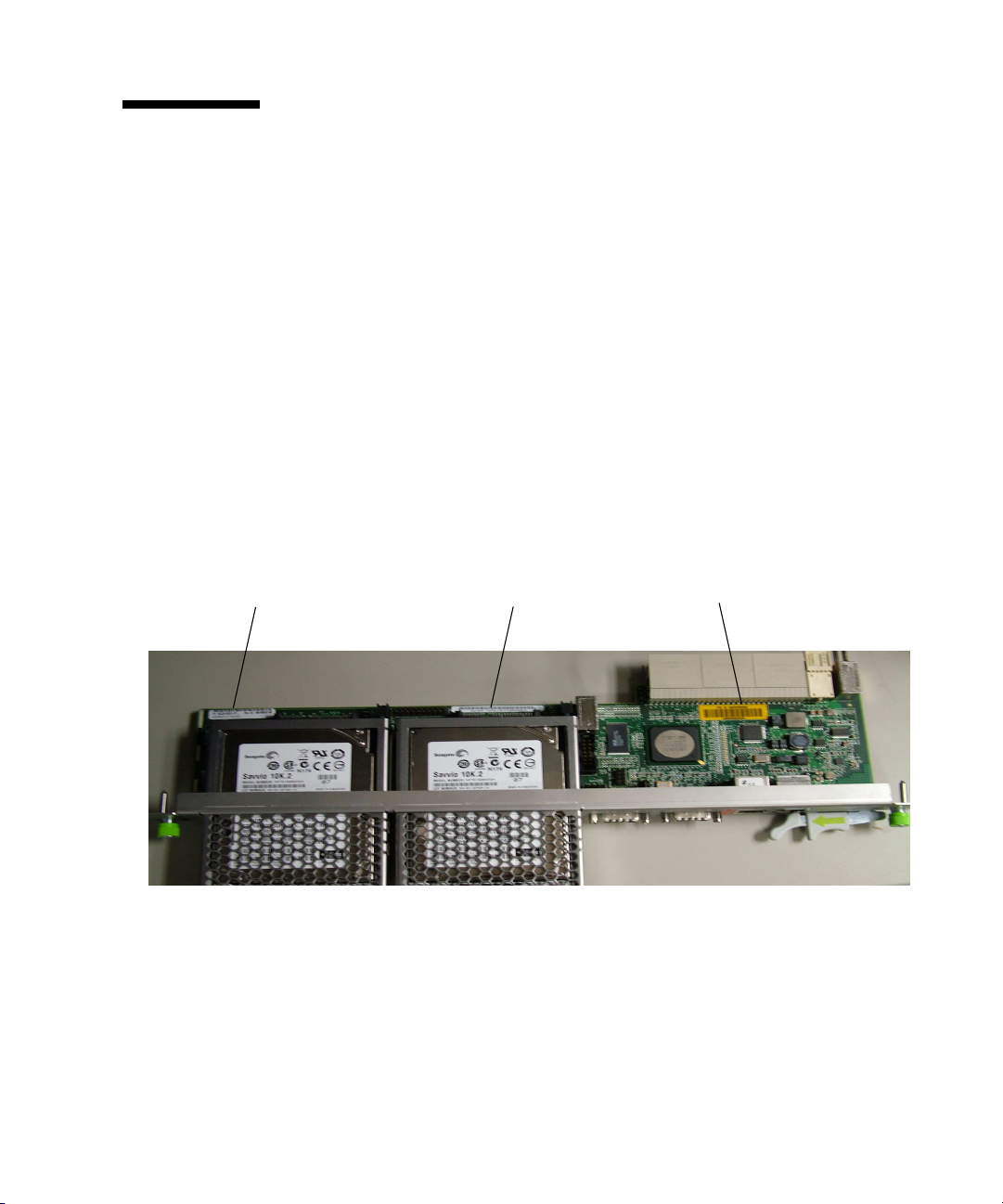
1.10 Part Number, Serial Number, and FC Address Labels
The ARTM-HD serial number, part number, FibreChannel (FC) address are printed
on stickers located on the module. For proper identification of the ARTM-HD, find
the Sun Microsystems barcode labels on the module. The barcode labels provide the
following information:
■ Module serial number (for example, 1005LCB-07296R0912), which is on the
barcode label
■ Product part number, including dash level (for example, 594-4759-01) and
revision number (for example, REV 50). (Based on the Part Number, you can
identify whether the ARTM-HD has a single or dual HD.)
FIGURE 1-6 ARTM-HD Identification Labels
Part number label Serial number label
FC address label
Chapter 1 Overview 1-13
Page 30

1-14 Netra CP32x0 SAS Storage Advanced Rear Transition Module HD User’s Guide • January 2009
Page 31

CHAPTER
2
Installation and Service
This chapter contains the procedures for installing and removing the Netra CP32x0
SAS Storage Advanced Rear Transition Module HD (ARTM-HD).
This chapter contains the following sections:
■ Section 2.1, “About Installing and Removing the ARTM-HD” on page 2-2
■ Section 2.2, “Installing the ARTM-HD” on page 2-4
■ Section 2.3, “Removing the ARTM-HD” on page 2-9
■ Section 2.4, “Installing a Hard Disk Drive” on page 2-11
■ Section 2.5, “Removing a Hard Disk Drive” on page 2-11
■ Section 2.6, “Changing the OOS LED Color” on page 2-12
2-1
Page 32

2.1 About Installing and Removing the ARTM-HD
The ARTM-HD can be installed into an ATCA shelf (chassis) with a midplane made
for front and rear board installations (
the slot directly behind the Netra ATCA node board. These back-to-back slots have
common pins to enable passing of signals.
Note – Connectors on previous blade servers do not mate with connectors on the
ARTM-HD.
Before installing the ARTM-HD, verify the module’s part number to ensure that the
correct ARTM-HD is being installed into the system. For information on identifying
the ARTM-HD, see Section 1.10, “Part Number, Serial Number, and FC Address
Labels” on page 1-13.
Caution – Use the ARTM-HD only with compatible blade servers. Attempts to
install the ARTM-HD with an incompatible blade server might cause damage to
themselves and the blade server.
FIGURE 2-1). The module must be installed in
2-2 Netra CP32x0 SAS Storage Advanced Rear Transition Module HD User’s Guide • January 2009
Page 33

FIGURE 2-1 Installing the Blade Server and ARTM-HD Into the ATCA Shelf
Chapter 2 Installation and Service 2-3
Page 34

2.2 Installing the ARTM-HD
The ARTM-HD must be used with a Netra ATCA node board for rear I/O access.
The ARTM-HD enables access to the network, to a boot device, and to a console
terminal.
Note – The ARTM-HD and the corresponding Netra blade server can be installed
while the shelf is powered—however, start with a powered shelf only if you must do
so.
Note – Optimally, install the ARTM-HD before installing the corresponding Netra
blade server. This order ensures proper bring up of the ARTM-HD firmware.
1. Verify that you have taken the necessary antistatic precautions.
2. Go to the back of the system and choose an appropriate slot for the ARTM-HD.
ARTMs must be installed inline behind the accompanying blade server. For
example, if the accompanying blade server is going to be installed in
slot 3, its ARTM must be installed at the back of the system in slot 3.
3. Remove the slot filler panel from the selected blade server slot, if necessary.
4. Prepare the module by loosening the locking screws and opening the
injector/ejector latch at the top of the module (
FIGURE 2-2).
2-4 Netra CP32x0 SAS Storage Advanced Rear Transition Module HD User’s Guide • January 2009
Page 35

FIGURE 2-2 Injector/Ejector Latch and Locking Screw
retention screw
injector/ejector
latch
5. Hold the bottom disk cage with one hand and top injector/ejector latch with the
other hand, as shown in
FIGURE 2-3.
Note – The following steps apply regardless of how many ARTMs are in the chassis,
as long as there is an available slot for the ARTM you are installing.
Chapter 2 Installation and Service 2-5
Page 36

FIGURE 2-3 Holding the ARTM-HD During Installation
6. Carefully align the top and bottom edges of the module with the guides in the
appropriate slot.
It might be helpful to look into the enclosure to verify correct alignment of the
rails in the guides.
2-6 Netra CP32x0 SAS Storage Advanced Rear Transition Module HD User’s Guide • January 2009
Page 37

7. Taking care to keep the module aligned in the guides, carefully insert the
module by simultaneously pressing the bottom disk cage and top
injector/ejector latch, which is extended fully open.
FIGURE 2-4 Inserting the ARTM-HD
8. Slide the module in as far as possible and while maintaining pressure on the
bottom disk cage, rotate the injector/ejector latch inward to its closed position
to fully seat the module in the slot.
Chapter 2 Installation and Service 2-7
Page 38

9. Tighten the module retention screws to ensure that the module is secured into
the shelf.
If the module is inserted properly, the hotswap switch is activated. The blue
Hot-swap LED will blink, then the green OK LED lights.
10. Install the blade server into the front of the shelf (
FIGURE 2-1) and push the
board toward the midplane. Ensure that it is seated properly and that the
connectors make good contact with the ARTM-HD.
For further details on installation of the board, refer to the appropriate user
documentation for the board.
11. Install the supported peripheral devices at the ARTM-HD connector ports, as
required.
Use shielded cables for the ports on the ARTM-HD; the shield should be
grounded at both ends. For further details on installation of the board, refer to the
appropriate user documentation for the board.
12. Power on the system, if necessary.
Refer to your system manual for instructions on correctly powering on the
system.
Note – If you are installing a ARTM-HD, paired with a Netra CP3220 board or
Netra CP3260 board, into a system with a 10 GbE switch, you must perform a
one-time configuration on the Netra CP3220 board or Netra CP3260 board to assure
the board and ARTM-HD operate at the correct speed for your switch. For
information on configuring your board, see the Netra CP3220 Board User’s Guide
(820-1982) or the Netra CP3260 Board User’s Guide (820-0457).
2-8 Netra CP32x0 SAS Storage Advanced Rear Transition Module HD User’s Guide • January 2009
Page 39

2.3 Removing the ARTM-HD
Caution – Power to the ARTM-HD must be off before the module can be safely
removed. Removing the ARTM-HD without properly removing power can cause
data loss on hard disk drives installed in the ARTM-HD.
1. Shut down any operating system accessing the ARTM-HD or its companion
board.
2. Power off the ARTM-HD from the shelf manager.
For example, to power down just the ARTM-HD in slot 1, log in to the shelf
manager and type:
# clia deactivate 9a 3
where 9a is the IPMB address for slot 1, and 3 is the ARTM-HD in slot 1.
Alternately, to power down both the ARTM-HD and its companion blade server,
type:
# clia deactivate board 1
3. Loosen the locking screws on the ARTM-HD.
4. Unlatch the top injector/ejector latch and wait for the blue Hot-swap LED to
light.
Depending upon the status and functionality of the front blade server, the
ARTM-HD blue Hot-swap LED will either blink or go to solid state.
Note – The following steps apply regardless of how many ARTMs are in the chassis.
It might be a little more difficult to grasp an ARTM when the chassis is full.
5. Remove the module by simultaneously pulling on the the bottom disk cage
with one hand and the top injector/ejector latch with the other hand, as shown
in
FIGURE 2-5.
Chapter 2 Installation and Service 2-9
Page 40

FIGURE 2-5 Removing the ARTM-HD
6. If the slot is to remain empty, install a filler panel in the slot.
7. Reinstall the blade server, if necessary.ARTM-HD
2-10 Netra CP32x0 SAS Storage Advanced Rear Transition Module HD User’s Guide • January 2009
Page 41

2.4 Installing a Hard Disk Drive
1. Open the HD latch by pressing the button on the face of the drive.
2. Insert the drive into the appropriate drive bay until the latch closes and the
drive fully engages with the connectors.
2.5 Removing a Hard Disk Drive
1. Unmount any file systems using the HD.
2. Locate the drive to be replaced.
If a drive is faulty, the amber fault LED will light.
3. Press the button on the face of the HD to release the latch.
The latch springs open.
4. Grab the latch and remove the HD from the drive bay.
5. If the slot is to remain empty, install a filler panel in the slot.
Chapter 2 Installation and Service 2-11
Page 42

2.6 Changing the OOS LED Color
The color of the Out-of-service (OOS) LED can be set to red or amber by moving
jumper JU1 to the appropriate position. Setting the jumper to the P1/P2 position
makes the OOS LED appear red. Setting the jumper to the P2/P3 position makes the
OOS LED appear amber. Amber (position P2/P3) is the default setting for the OOS
LED.
1. Remove the ARTM-HD from the chassis.
See Section 2.3, “Removing the ARTM-HD” on page 2-9.
2. Locate jumper JU1 on the board.
JU1 is located next to the Primary SAS connector.
FIGURE 2-6 Jumper setting for red OOS LED (P1/P2)
Jumper 1
3. Set the jumper housing to the appropriate setting; P1/P2 for red, P2/P3 for
amber.
2-12 Netra CP32x0 SAS Storage Advanced Rear Transition Module HD User’s Guide • January 2009
Page 43

FIGURE 2-7 Jumper setting for amber OOS LED (P2/P3)
4. Reinstall the ARTM-HD.
See Section 2.2, “Installing the ARTM-HD” on page 2-4.
Chapter 2 Installation and Service 2-13
Page 44

2-14 Netra CP32x0 SAS Storage Advanced Rear Transition Module HD User’s Guide • January 2009
Page 45

CHAPTER
3
Disk Management
This chapter describes the disk management and BIOS configuration software.
This chapter contains the following sections:
■ Section 3.1, “RAID Support” on page 3-2
■ Section 3.2, “SAS BIOS Overview” on page 3-2
■ Section 3.3, “Starting the SAS BIOS Configuration Utility” on page 3-3
■ Section 3.4, “Creating a RAID 0 Volume” on page 3-4
■ Section 3.5, “Creating a RAID 1 Volume” on page 3-5
■ Section 3.6, “Creating a RAID 1E Volume” on page 3-6
■ Section 3.8, “Synchronizing an Array” on page 3-8
■ Section 3.9, “Activating an Array” on page 3-8
■ Section 3.10, “Deleting an Array” on page 3-9
■ Section 3.11, “Locating a Disk Drive” on page 3-9
3-1
Page 46

3.1 RAID Support
The LSISAS1068e controller supports the Integrated RAID hardware solution, which
is a highly integrated, low-cost RAID solution. It is designed for systems requiring
redundancy and high availability, but not requiring a full-featured RAID
implementation.
Integrated RAID includes Integrated Mirroring (IM or RAID 1), Integrated Mirroring
Extended (IME), and Integrated Striping (IS or RAID 0) technology. Integrated RAID
is OS independent, easy to install and configure, and does not require a special
driver. A RAID Volume is seen as a single drive by the host BIOS and OS.
The LSISAS1068e controller is based on the Fusion-MPT (Message Passing
Technology) architecture. The Fusion-MPT architecture requires only a thin device
driver that is independent of the I/O bus. LSI Logic provides the device drivers for
various operating environments.
3.2 SAS BIOS Overview
The SAS BIOS is the bootable ROM code that manages SAS hardware resources. It is
specific to a family of LSI Logic Fusion-MPT SAS controllers or processors. The
Fusion-MPT SAS BIOS integrates with a standard system BIOS, extending the
standard disk service routine provided through INT13h.
During the boot time initialization, the SAS BIOS determines whether the system
BIOS has already installed other hard disks, such as an IDE drive. If such drives are
already installed, the SAS BIOS maps any SAS drives it finds behind these drives.
Otherwise, the SAS BIOS installs drives starting with the system boot drive. In this
case, the system boots from a drive controlled by the SAS BIOS.
The Fusion-MPT SAS BIOS features include:
■ Configuration for up to 256 adapters; any four can be chosen for INT13 (bootrom)
support
■ Support for Message Passing Technology (MPT)
■ Support for LSI53C1064 devices
■ Support for SAS devices
■ Support for Integrated RAID initialization (with proper firmware)
3-2 Netra CP32x0 SAS Storage Advanced Rear Transition Module HD User’s Guide • January 2009
Page 47

3.3 Starting the SAS BIOS Configuration Utility
If you have SAS BIOS version 6.x.x with the Fusion-MPT SAS BIOS Configuration
Utility, you can change the default configuration of the SAS host adapters. You may
decide to change these default values if there is a conflict between device settings or
if you need to optimize system performance.
The version number of the SAS BIOS appears in a banner displayed on the computer
monitor during bootup. If the utility is available, this message also appears during
bootup:
Press Ctrl+C to start LSI Logic Configuration Utility...
This message remains on the screen for about five seconds, giving you time to start
the utility. If you press Ctrl+C, the message changes to:
Please wait, invoking LSI Logic Configuration Utility...
After a brief pause, the computer monitor displays the Main menu of the
Fusion-MPT SAS BIOS Configuration Utility. These messages may appear during the
boot process:
■ Adapter removed from boot order!
This message appears when an adapter has been removed from the system or has
been relocated behind a PCI bridge.
■ Adapter configuration may have changed, reconfiguration is
suggested!
This message appears if none of the information in the NVRAM is valid.
■ Updating Adapter List!
This message appears when fewer than four adapters are in the boot order and
more adapters exist than are shown.
Caution – The SAS BIOS Configuration Utility is a powerful tool. If, while using it,
you disable the controller, press Ctrl+E (or Ctrl+A on versions earlier than 5.00) after
memory initialization during reboot to reenable and reconfigure the controller.
Note – The RAID firmware needs at least 64 Mbytes of unused disk space at the end
of each drive to store metadata.
Chapter 3 Disk Management 3-3
Page 48

3.4 Creating a RAID 0 Volume
A RAID 0 volume, also referred to as Integrated Striping (IS), offers the ability to
stripe data across multiple hard disks. This can increase storage capacity and
performance by combining multiple disks into one logical volume.
Note – Use RAID 0 with caution. The only advantage of RAID 0 is to improve the
overall disk performance by striping data over several disk drives. By doing this, it
decreases reliability because the failure of any drive within the striped volume
results in a complete loss of data. In addition, any disk drive included in a RAID 0
volume becomes non-hot-swappable.
Follow these steps to create a RAID 0 volume on an adapter that does not currently
have a volume configured.
1. In the Configuration Utility, select an adapter from the Adapter List screen.
2. Select the RAID Properties option.
3. When you are prompted to create either an IS volume, an IME volume, or an
IM volume, select Create IS Volume.
The next screen shows a list of disks that can be added to a volume.
4. Move the cursor to the RAID Disk column. To add a disk to the volume, change
the “No” to “Yes” by pressing the + key, - key, or space bar.
As disks are added, the Array Size field changes to reflect the size of the new
volume. There are several limitations when creating a RAID 0 volume:
■ All disks must be SAS (with SMART support).
■ Disks must have 512-byte blocks and must not have removable media.
■ There must be at least two drives in a valid volume.
■ Hot spare drives are not allowed for RAID 0 volumes.
Note – RAID 0 does not provide any data protection in the event of disk failure. It
is primarily used to increase speed.
3-4 Netra CP32x0 SAS Storage Advanced Rear Transition Module HD User’s Guide • January 2009
Page 49

Note – Once the number of disks in a RAID volume is set, it cannot be changed.
5. When the volume has been fully configured, press C and select Save Changes,
then exit this menu to commit the changes.
The Configuration Utility will pause while the array is being created.
3.5 Creating a RAID 1 Volume
A RAID 1 volume, also referred to as Integrated Mirroring (IM), offers the ability to
mirror data from one hard disk onto another one. This can increase reliability by
combining multiple disks into one logical volume. Follow these steps to create a
RAID 1 volume on an adapter that does not currently have a volume configured.
1. In the Configuration Utility, select an adapter from the Adapter List screen.
2. Select the RAID Properties option.
3. When you are prompted to create either an IS volume, and IME volume, or an
IM volume, select Create IM Volume.
The next screen shows a list of disks that can be added to a volume.
4. Move the cursor to the RAID Disk column. To add a disk to the volume, change
the “No” to “Yes” by pressing the + key, - key, or space bar.
When the first disk is added, the utility will prompt you to keep existing data or
overwrite existing data.
5. Press M to keep the existing data on the first disk or press D to overwrite it.
If you keep the existing data, this is called a migration. The first disk will be
mirrored onto the second disk, so the data you want to keep must be on the first
disk added to the volume. Data on all other disks will be lost.
As disks are added the Array Size field will change to reflect the size of the new
volume. There are several limitations when creating a RAID 1 volume:
■ All disks must be SAS (with SMART support).
■ Disks must have 512-byte blocks and must not have removable media.
■ There must be two drives in a valid volume.
6. (Optional) Add a hot spare to the volume by moving the cursor to the Hot
Spare column and pressing the + key, - key, or space bar.
Chapter 3 Disk Management 3-5
Page 50

7. When the volume has been fully configured, press C and select Save Changes,
then exit this menu to commit the changes.
The Configuration Utility will pause while the array is being created.
Note – RAID 1 provides protection against the failure of a single disk. When a disk
fails, it is rebuilt to a hot spare if one is available. This can greatly increase the level
of protection that RAID 1 provides.
Note – Even though multiple volumes can be created, the hot spare is a global hot
spare. Only one active hot spare is allowed for all volumes.
3.6 Creating a RAID 1E Volume
A RAID 1E volume, also referred to as an Integrated Mirroring Enhanced (IME),
combines the ability of RAID 0 to stripe data and the ability of RAID 1 to mirror the
now-striped data. This can increase reliability of RAID 0 by adding the mirroring
feature of RAID 1. Use RAID 1E for arrays with an odd number of disks. A
minimum of three disks are needed to configure RAID 1E. Follow these steps to
create a RAID 1E volume on an adapter that does not currently have a volume
configured.
1. In the Configuration Utility, select an adapter from the Adapter List screen.
2. Select the RAID Properties option.
3. When you are prompted to create either an IS volume, and IME volume, or an
IM volume, select Create IME Volume.
The next screen shows a list of disks that can be added to a volume.
4. Move the cursor to the RAID Disk column. To add a disk to the volume, change
the “No” to “Yes” by pressing the + key, - key, or space bar.
When the first disk is added, the utility will prompt you to keep existing data or
overwrite existing data.
5. Press M to keep the existing data on the first disk or press D to overwrite it.
If you keep the existing data, this is called a migration. The first disk will be
mirrored onto the second disk, so the data you want to keep must be on the first
disk added to the volume. Data on all other disks will be lost.
3-6 Netra CP32x0 SAS Storage Advanced Rear Transition Module HD User’s Guide • January 2009
Page 51

As disks are added the Array Size field will change to reflect the size of the new
volume. There are several limitations when creating a RAID 1E volume:
■ All disks must be SAS (with SMART support).
■ Disks must have 512-byte blocks and must not have removable media.
■ There must be three drives in a valid volume.
6. (Optional) Add a hot spare to the volume by moving the cursor to the Hot
Spare column and pressing the + key, - key, or space bar.
7. When the volume has been fully configured, press C and select Save Changes,
then exit this menu to commit the changes.
The Configuration Utility will pause while the array is being created.
3.7 Viewing RAID Volume Properties
Follow these steps to view the properties of RAID volumes.
1. In the Configuration Utility, select an adapter from the Adapter List screen.
2. Select the RAID Properties option.
The properties of the current volume are displayed.
3. If more than one volume is configured, press Alt+N to view the next array.
4. To manage the current array, press Enter when the Manage Array item is
selected.
Chapter 3 Disk Management 3-7
Page 52

3.8 Synchronizing an Array
Synchronizing an array means that the firmware synchronizes the data on the
secondary disk(s) with the data on the primary disk of the mirror. Follow these steps
to start a synchronization for a RAID 1 volume.
1. Select Synchronize Array.
2. Press Y to start the synchronization, or N to cancel it.
Note – If the server is rebooted before the volume synchronization is completed, the
resync resumes when the server boots.
3.9 Activating an Array
An array can become inactive if, for example, it is removed from one controller or
computer and moved to another one. The Activate Array option enables you to
reactivate an inactive array that has been added to a system. This option is only
available when the selected array is currently inactive.
1. Select Activate Array.
2. Press Y to proceed with the activation, or press N to abandon it.
After a pause, the array becomes active.
3-8 Netra CP32x0 SAS Storage Advanced Rear Transition Module HD User’s Guide • January 2009
Page 53

3.10 Deleting an Array
Caution – Before deleting an array, back up all data on the array that you want to
keep.
Follow these steps to delete a selected array.
1. Select Delete Array.
2. Press Y to delete the array, or press N to abandon the deletion.
After a pause, the firmware deletes the array.
Note – Once a volume has been deleted, it cannot be recovered. When a RAID 1
volume is deleted, the data is preserved on the primary disk. The master boot
records (MBR) of other disks in the array are deleted. For other RAID types, the
master boot records of all disks are deleted.
3.11 Locating a Disk Drive
There are several ways to physically locate a disk drive, as long as the firmware is
correctly configured and the drives support disk location.
■ During RAID creation, when a disk is set to Yes as part of a RAID volume, its
Locate LED is enabled. When it is set back to No or the RAID volume is created,
the Locate LED is cleared.
■ Disks can also be located from the SAS Topology screen. To locate a disk, move
the cursor to the disk and press Enter. The Locate LED on the disk remains lit
until the next key is pressed.
Chapter 3 Disk Management 3-9
Page 54

3-10 Netra CP32x0 SAS Storage Advanced Rear Transition Module HD User’s Guide • January 2009
Page 55

CHAPTER
4
Specifications and Connectors
This chapter provides the specifications and connector pinouts for the ARTM-HD.
This chapter contains the following sections:
■ Section 4.1, “Specifications for the ARTM-HD” on page 4-2
■ Section 4.2, “Hardware Descriptions” on page 4-3
■ Section 4.3, “Connectors and Pin Assignments” on page 4-4
4-1
Page 56

4.1 Specifications for the ARTM-HD
This section provides mechanical, electrical, environmental, and other relevant
specifications for the ARTM-HD.
4.1.1 Physical Dimensions
The ARTM-HD is a 6U (233.35 mm) height board with 80 mm in depth for standard
applications. It complies with IEEE 1101.11 mechanical standards, as required by the
PICMG 3.0 Revision 2.0 specification. The ARTM-HD is keyed to conform to the
PICMG 2.10, Keying of ATCA Boards and Backplanes specification.
4.1.2 Power Requirements
The power consumption of the ARTM-HD is limited to 25W maximum. The blade
server provides the following voltages: 3.3V Management Power and +12V Payload
Power. The ARTM-HD creates 3.3V, 5V, and 1.2V from the 12v Payload Power.
4.1.3 Electrical Requirements
The ARTM-HD is powered through the Netra ATCA node board. The blade server
provides the following voltages: 3.3V/+12V.
4.1.4 Environmental Specifications and Compliance
For details on the environmental specifications and compliance, see Important Safety
Information for Sun Hardware Systems (816-7190), the Netra CP3220 Board User’s Guide
(820-1982).
You can download and view these documents from the following web site:
http://www.sun.com/documentation/
4-2 Netra CP32x0 SAS Storage Advanced Rear Transition Module HD User’s Guide • January 2009
Page 57

4.2 Hardware Descriptions
4.2.1 Ethernet Management Port
The ARTM-HD provides one 10/100/1000 MBASE-T ethernet management port
with an RJ-45 connector equipped with LEDs.
4.2.2 Infinband-style Connectors
The ARTM-HD provides two (primary and secondary) Infinband-style SAS
connectors, with jack screws, for external drive support using a SFF-8470 style SAS
cable.
4.2.3 Serial Port
One asynchronous serial port with an RJ-45 serial connector is included on the
ARTM-HD I/O faceplate. The serial port may be redirected to the front blade server
when using a Netra CP3220 board, a Netra CP3260 board, or other ARTM
-compatible blade server. For more information on using both the front and rear
serial ports, refer to the appropriate blade server documentation.
4.2.4 SAS Interface
The ARTM-HD includes a LSI 1068E PCIe to 8-port SAS controller chip.
4.2.5 Module Management Controller
The onboard Module Management Controller (MMC) provides IPMI management
communication between the RTM and the blade server, and local monitoring of
temperature and voltage.
Chapter 4 Specifications and Connectors 4-3
Page 58

4.2.6 FRU PROM
The ARTM-HD contains an IPMI FRU Prom compatible with the ATCA
specifications.
4.3 Connectors and Pin Assignments
FIGURE 4-1 shows the location of the connectors.
FIGURE 4-1 Netra CP32x0 ARTM-HD Connectors
8
1 - Serial port 5 - Hard disk drive(s) (single drive contains a
filler panel on the second drive)
2 - 10/100/1000 Mb Management port 6 - RTM alignment pin
3 - External SAS port (secondary) 7 - Power connector
4 - External SAS port (primary) 8 - Zone 3 connectors
4-4 Netra CP32x0 SAS Storage Advanced Rear Transition Module HD User’s Guide • January 2009
Page 59

4.3.1 I/O Connectors
This section lists the pins and signal names of the I/O faceplate connectors on the
ARTM-HD. The faceplate has the following connectors:
■ One 10/100/1000 BASE-T Ethernet management port (RJ-45)
■ One serial ports (RS232)
■ Two External SAS connectors (Infinband style)
4.3.1.1 Ethernet Port
The Ethernet connector is an RJ-45 connector with LEDs. The controller
autonegotiates to either 10/100/1000BASE-T.
connector.
FIGURE 4-2 Ethernet RJ-45 Connector
FIGURE 4-2 shows an Ethernet RJ-45
1 2 3 4 5 6 7 8
Yellow LED
(activity) (LINK)
TABLE 4-1 gives the pin assignments for the Ethernet ports.
TABLE 4-1 Ethernet Port Connector Pin Assignments
Pin Signal Name Pin Signal Name
1 DA+ 5 DC-
2 DA- 6 DB-
3 DB+ 7 DD+
4 DC+ 8 DD-
Chapter 4 Specifications and Connectors 4-5
Green LED
Page 60

4.3.1.2 Serial Port
The serial port connector is an RJ45 connector. FIGURE 4-3 shows a serial port
connector.
FIGURE 4-3 Serial Port Connector
TABLE 4-2 gives the serial port connector pin assignments.
TABLE 4-2 Serial Port Connector Pin Assignments
Pin Signal Name Pin Signal Name
1 RTS 5 GND
2 DTR 6 RXD
3 TXD 7 DSR
4 GND 8 CTS
1 2 3 4 5 6 7 8
4-6 Netra CP32x0 SAS Storage Advanced Rear Transition Module HD User’s Guide • January 2009
Page 61

4.3.1.3 SAS Connectors
The ARTM-HD provides two Serial Attached SCSI (SAS) ports using an
Infinband-style connector.
FIGURE 4-4 SAS Connectors
S16
S2
G1
S15
G9
TABLE 4-3 External SAS Connector Pin Assignments
Pin Function
S1 RX0+
S2 RX0-
S3 RX1+
S4 RX1-
S5 RX2+
S6 RX2-
S7 RX3+
S8 RX3-
S9 TX3-
S10 TX3+
S11 TX2-
S12 TX2+
S13 TX1-
S14 TX1+
S1
Chapter 4 Specifications and Connectors 4-7
Page 62

TABLE 4-3 External SAS Connector Pin Assignments
Pin Function
S15 TX0-
S16 TX0+
G1-9 Signal Ground
Housing Chassis Ground
4.3.2 Zone 3 Connectors
All the I/O connections for rear access are provided by the Netra blade server
through the Zone 3 connectors. The Zone 3 connectors are P31, P32, and P33. The
Zone 3 connectors are shown in
Note – The letters TX in a pin name indicate that the signal is transmitted from the
ATCA card to the ARTM card.
FIGURE 4-5 Zone 3 Connectors
FIGURE 4-5.
J31 J32 J33
4-8 Netra CP32x0 SAS Storage Advanced Rear Transition Module HD User’s Guide • January 2009
Page 63

TABLE 4-4 lists the Zone 3, J31 connector pinouts.
TABLE 4-4 J31 Connector Pin Assignments
Row Interface A B C D E F
1 AMC1 EO Ports TX1_13+ TX1_13- RX1_12+ RX1_12- TX1_12+ TX1_12-
2 RX1_14+ RX1_14- TX1_14+ TX1_14- RX1_13+ RX1_13-
3 TX1_17+ TX1_17- RX1_15+ RX1_15- TX1_15+ TX1_15-
4 RX1_18+ RX1_18- TX1_18+ TX1_18- RX1_17+ RX1_17-
5 TX1_20+ TX1_20- RX1_19+ RX1_19- TX1_19+ TX1_19-
6 RX2_12+ RX2_12- TX2_12+ TX2_12- RX1_20+ RX1_20-
7 AMC2 EO Ports TX2_14+ TX2_14- RX2_13+ RX2_13- TX2_13+ TX2_13-
8 RX2_15+ RX2_15- TX2_15+ TX2_15- RX2_14+ RX2_14-
9 TX2_18+ TX2_18- RX2_17+ RX2_17- TX2_17+ TX2_17-
10 RX2_19+ RX2_19- TX2_19+ TX2_19- RX2_18+ RX2_18-
TABLE 4-5 lists the Zone 3, J32 connector pinouts.
TABLE 4-5 J32 Connector Pin Assignments
Row Interface A B C D E F
1 AMC2 EO Ports NC NC RX2_20+ RX2_20- TX2_20+ TX2_20+
2 SAS/SATA0 - SER0 SA_TX0+ SA_TX0- SA_RX0+ SA_RX0- SR0_RTS SR0_DTR
3 SAS/SATA1 - SER0 SA_TX1+ SA_TX1- SA_RX1+ SA_RX1- SR0_TXD SR0_RXD
4 SAS/SATA2 - SER0 SA_TX2+ SA_TX2- SA_RX2+ SA_RX2- SR0_DSR SR0_CTS
5 SAS/SATA3 - SER0 SA_TX3+ SA_TX3- SA_RX3+ SA_RX3- NC NC
6 LAN0 (MNGT) LAN0_A+ LAN0_A- LAN0_CTV LAN0_CTV LAN0_B+ LAN0_B-
7 LAN0_C+ LAN0_C- ACT_LED#
8 LAN1 (SerDes)
9 LAN2 & LAN4 (SerDes)
10 LAN3 & LAN4 (SerDes)
SLAN_TX1+ SLAN_TX1- SLAN_RX1+ SLAN_RX1-
SLAN_TX2+ SLAN_TX2- SLAN_RX2+ SLAN_RX2- SLAN_TX4+ SLAN_TX4-
SLAN_TX3+ SLAN_TX3- SLAN_RX3+ SLAN_RX3- SLAN_RX4+ SLAN_RX4-
LINK_LED#
LAN0_D+ LAN0_D-
NC NC
Chapter 4 Specifications and Connectors 4-9
Page 64

TABLE 4-6 lists the Zone 3, J33 connector pinouts.
TABLE 4-6 J33 Connector Pin Assignments
Row Interface A B C D E F
1 PCIe x8 Lane PETx0+ PETx0- PERx0+ PERx0- FCLKA+ FCLKA-
2 PETx1+ PETx1- PERx1+ PERx1- TCLKA+ TCLKA-
3 PETx2+ PETx2- PERx2+ PERx2- TCLKB+ TCLKB-
4 PETx3+ PETx3- PERx3+ PERx3- TCLKC+ TCLKC-
5 PETx4+ PETx4- PERx4+ PERx4- TCLKD+ TCLKD-
6 PETx5+ PETx5- PERx5+ PERx5- TCK TMS
7 PETx6+ PETx6- PERx6+ PERx6- TRST# TDO
8 PETx7+ PETx7- PERx7+ PERx7- TDI PCI_RST#
9 NC NC NC NC RTM# PCI_CFG
10 NC NC NC NC PS0# Enable#
4-10 Netra CP32x0 SAS Storage Advanced Rear Transition Module HD User’s Guide • January 2009
Page 65

Index
A
ATCA shelf, 2-2
B
BIOS
SAS RAID, 3-2
C
compliance specifications, 4-2
compliance, PICMG, 1-3
configurations, I/O configurations, 1-7
connectors
Ethernet, 4-5
Zone 3, 4-8
E
electrical requirements, 4-2
environmental specifications, 4-2
Ethernet, RJ-45 connectors, 4-5
F
features, 1-2
FIGURE, 4-6
Fusion-MPT SAS BIOS, See SAS BIOS
I
I/O configurations, 1-7
installation, rear transition module, 2-2 to 2-10
P
pinouts, serial port, 4-6
power requirements, 4-2
R
RAID
activating an array, 3-8
creating RAID 0 volume, 3-4
creating RAID 1 volume, 3-5
deleting an array, 3-9
locating a disk drive, 3-9
synchronizing arrays, 3-8
viewing RAID volume properties, 3-7
rear transition module
features, 1-2
installation, 2-2 to 2-10
interfaces, 1-6
removal, 2-9
RJ-45 Ethernet connectors, 4-5
S
SAS BIOS
activating a RAID array, 3-8
creating RAID 0 volume, 3-4
creating RAID 1 volume, 3-5
deleting a RAID array, 3-9
locating a RAID disk, 3-9
overview, 3-2
starting Configuration Utility, 3-3
synchronizing RAID arrays, 3-8
viewing RAID volume properties, 3-7
serial
number, locating, 1-13
Serial Attached SCSI BIOS, See SAS BIOS
Index-1
Page 66

serial interface, 4-3
serial port pinouts, 4-6
serial ports, 4-6
software support, 1-12
specifications, 1-3, 4-2
compliance, 4-2
electrical requirements, 4-2
environmental, 4-2
Index-2 Netra CP32x0 SAS Storage Advanced Rear Transition Module HD User’s Guide • January 2009
 Loading...