


Sun Netra™CP3060 Blade Server
User’s Guide
Sun Microsystems, Inc.
www.sun.com
Part No. 819-4967-11
April 2009, Revision A
Submit comments about this document at: http://www.sun.com/hwdocs/feedback

Copyright ©2009 Sun Microsystems, Inc., 4150Network Circle,Santa Clara, California 95054, U.S.A.All rights reserved.
This distributionmay include materials developed bythird parties.
Parts ofthe product may be derivedfrom BerkeleyBSD systems, licensed from the University ofCalifornia. UNIX is a registered trademark in
the U.S.and in other countries, exclusivelylicensed through X/Open Company, Ltd.
Sun, SunMicrosystems, the Sun logo, Netra,Sun Ray, the Netra logoand the Solaris logo are trademarks or registered trademarks of Sun
Microsystems, Inc.,or its subsidiaries, in theU.S. and other countries.
All SPARC trademarks are usedunder license and are trademarks or registered trademarks of SPARC International, Inc. in the U.S. andother
countries. Productsbearing SPARC trademarksare basedupon architecturedeveloped by Sun Microsystems, Inc.
Use ofany spare or replacement CPUs is limitedto repair or one-for-one replacement of CPUs in products exported in compliance withU.S.
export laws.Use of CPUs as productupgrades unless authorized by theU.S. Government is strictly prohibited.
DOCUMENTATION IS PROVIDED "AS IS" AND ALL EXPRESS OR IMPLIED CONDITIONS, REPRESENTATIONS AND WARRANTIES,
INCLUDING ANY IMPLIED WARRANTY OF MERCHANTABILITY, FITNESSFOR A PARTICULAR PURPOSE OR NON-INFRINGEMENT,
ARE DISCLAIMED, EXCEPT TO THE EXTENT THAT SUCH DISCLAIMERS ARE HELD TO BE LEGALLY INVALID.
Copyright ©2009 Sun Microsystems, Inc., 4150Network Circle,Santa Clara, California 95054, Etats-Unis.Tousdroits réservés.
Cette distributionpeut comprendredes composants développés par destierces parties.
Des partiesde ce produit pourront être dérivées des systèmes BerkeleyBSD licenciés par l’Université deCalifornie. UNIX est une marque
déposée auxEtats-Unis et dans d’autres payset licenciée exclusivement par X/OpenCompany, Ltd.
Sun, SunMicrosystems, le logo Sun, Netra,Sun Ray, le logo Netraet le logo Solaris sontdes marquesde fabrique ou des marques déposées de
Sun Microsystems,Inc., ou ses filiales, auxEtats-Unis et dans d’autres pays.
Toutes les marques SPARC sont utilisées sous licence et sont des marques de fabrique oudes marquesdéposées de SPARC International, Inc.
aux Etats-Uniset dans d’autres pays. Lesproduits portantles marques SPARCsont basés sur une architecture développée par Sun
Microsystems, Inc.
L’utilisationde pieces detachees ou d’unitescentrales de remplacement est limitee aux reparationsou a l’echange standard d’unites centrales
pour lesproduits exportes, conformement a lalegislation americaine en matiere d’exportation. Sauf autorisationpar les autorites des EtatsUnis, l’utilisationd’unites centrales pour proceder ades mises a jour deproduits estrigoureusement interdite.
LA DOCUMENTATION EST FOURNIE "EN L’ETAT" ET TOUTES AUTRES CONDITIONS, DECLARATIONS ET GARANTIES EXPRESSES
OU TACITES SONTFORMELLEMENT EXCLUES, DANS LA MESURE AUTORISEE PAR LA LOI APPLICABLE, Y COMPRISNOTAMMENT
TOUTE GARANTIE IMPLICITE RELATIVE A LA QUALITE MARCHANDE, A L’APTITUDE A UNE UTILISATION PARTICULIERE OU A
L’ABSENCE DE CONTREFACON.
Please
Recycle

Contents
Preface xi
1. Introduction to the Sun Netra CP3060 Blade Server 1–1
1.1 Overview of the Sun Netra CP3060 Blade Server 1–1
1.2 Features of the Sun Netra CP3060 Blade Server 1–2
1.3 Sun Netra CP3060 Blade Server System Configurations 1–7
1.3.1 AMC Modules 1–8
1.3.2 Rear Transition Module 1–8
1.4 Hot-Swap Support 1–11
1.5 System Requirements 1–11
1.5.1 Hardware Requirements 1–12
1.5.2 Software Requirements 1–12
1.6 Technical Support and Warranty 1–13
1.6.1 Blade Server Part Number, Serial Number, and Revision Number
Identification 1–13
2. Hardware Installation 2–1
2.1 Equipment and Operator Safety 2–1
2.2 Materials and Tools Required 2–2
2.3 Preparing for the Installation 2–3
iii

2.3.1 Checking Power, Thermal, Environmental, and Space
Requirements 2–3
2.3.2 Determining Local Network IP Addresses and Host Names 2–4
2.3.3 Installation Procedure Summary 2–4
2.4 Configuring the Blade Server Hardware 2–5
2.4.1 Installation of DDR-2 DIMM Memory Modules 2–5
2.4.1.1 Installing a DDR-2 DIMM Memory Module 2–7
2.4.1.2 Removing a DDR-2 DIMM Memory Module 2–8
2.4.2 Installation of Optional Compact Flash Card 2–9
2.4.3 Configuring Rear Transition Module Hardware 2–11
2.5 Installing the Sun Netra CP3060 Blade Server 2–11
2.5.1 Installing the Sun Netra CP3060 Blade Server With a Rear
Transition Module 2–11
2.5.1.1 Installing a Rear Transition Module 2–12
2.5.2 Installing the Sun Netra CP3060 Blade Server 2–15
2.6 Connecting External I/O Cables 2–17
2.7 Installation of Optional AMC Modules 2–18
2.7.0.1 Installing an Optional AMC Module 2–19
3. Software Installation 3–1
3.1 Operating Systems and Patches 3–1
3.2 Firmware Updates 3–2
3.3 Mandatory /etc/system File Entry 3–2
▼ To Check and Create the Mandatory /etc/system File Entry 2
3.4 Installing Diskless Clients 3–3
3.4.1 Creating a Boot Server for Diskless Clients 3–3
3.4.2 Adding a Diskless Client 3–5
3.5 Downloading and Installing SunVTS Software 3–7
4. Firmware and Blade Server Management 4–1
iv Netra CP3060 Board User’s Guide • April 2009

4.1 System Firmware 4–1
4.2 Power-On Self-Test Diagnostics 4–2
4.2.1 POST Test Coverage 4–2
4.2.2 POST Diagnostic and Error Message Format 4–3
4.3 OpenBoot Firmware 4–3
4.3.1 Getting to the ok Prompt 4–4
4.3.2 Auto-Boot Options 4–5
4.3.3 OpenBoot Commands 4–5
4.3.3.1 probe-ide Command 4–6
4.3.3.2 show-devs Command 4–6
4.3.3.3 Checking Network Using watch-net and watch-net-
all Commands 4–8
4.3.4 OpenBoot Configuration Variables 4–9
4.3.4.1 Viewing and Setting OpenBoot Configuration
Variables 4–12
4.4 Error Handling Summary 4–12
4.5 Automatic System Recovery 4–13
4.5.1 Enabling and Disabling Automatic System Recovery 4–14
4.5.1.1 To Enable Automatic System Recovery 4–14
4.5.1.2 To Disable Automatic System Recovery 4–15
4.6 Hot-Swap Information 4–15
4.6.1 Hot-Swapping the Sun Netra CP3060 Blade Server 4–15
4.6.1.1 Hot-Swap LED 4–16
4.7 Network Device Aliases 4–17
4.8 Retrieving Device Information 4–17
4.9 Mandatory /etc/system File Entry 4–20
▼ To Check and Create the Mandatory /etc/system File Entry 20
5. Hardware and Functional Descriptions 5–1
5.1 Hardware Architecture 5–1
Contents v

5.1.1 UltraSPARC T1 Processor 5–4
5.1.1.1 Overview 5–4
5.1.1.2 Cores and Cache 5–5
5.1.1.3 Memory Controller 5–6
5.1.1.4 Instruction Set 5–6
5.1.1.5 Interrupts 5–6
5.1.1.6 UltraSPARC T1 RAS Features 5–6
5.1.1.7 UltraSPARC T1 Processor Speed 5–6
5.1.2 DDR-2 Memory Subsystem 5–7
5.1.2.1 DIMMs 5–7
5.1.2.2 Memory Subsystem RAS Features 5–8
5.1.2.3 Serial Presence Detect 5–9
5.1.3 System JBus 5–9
5.1.3.1 JBus RAS Features 5–9
5.1.4 I/O Subsystem 5–9
5.1.4.1 JBus-to-PCI-E Bridge 5–10
5.1.4.2 PCI-E Switch 5–11
5.1.4.3 PCI-E to Dual GbE Controller 5–11
5.1.4.4 Ethernet Switch 5–12
5.1.4.5 AMC Slot 5–12
5.1.4.6 Southbridge 5–16
5.1.5 Service Processor MPC885 5–17
5.1.5.1 MPC Bus External Devices 5–18
5.1.5.2 Field-Programmable Gate Array 5–18
5.1.5.3 XBus External devices 5–19
5.1.6 Intelligent Platform Management Controller 5–19
5.1.6.1 Intelligent Platform Management Bus 5–19
5.1.6.2 Interface to the MPC 5–19
vi Netra CP3060 Board User’s Guide • April 2009

5.1.6.3 IPMB-L Interface 5–20
5.1.6.4 ATCA Hot-Swap Latch 5–20
5.1.6.5 LEDs 5–20
5.1.6.6 Power Control 5–20
5.1.6.7 Extended Interface E-keying Control 5–21
5.1.6.8 I2C Architecture 5–21
5.1.6.9 I2C Device Address Map 5–22
5.1.6.10 System Monitor and Thresholds 5–24
5.2 Power-on Sequence 5–26
5.3 Power 5–27
5.3.1 Power Input 5–27
5.3.2 Fuses 5–27
5.3.3 ATCA Power Module (-48V to 12V) 5–28
5.3.4 On-Board DC/DC Regulators 5–28
5.3.5 TOD Clock Battery 5–28
A. Physical Characteristics A–1
A.1 Form Factor A–1
A.2 Layout A–1
A.3 Front Panel A–2
A.3.1 Visual Indicators A–3
A.3.2 Ports A–3
A.3.3 AMC Slot A–3
A.4 Connectors and Pinout A–3
A.4.1 Front Panel Connectors A–3
A.4.1.1 Ethernet Ports A–4
A.4.1.2 Serial Port A–4
A.4.2 AMC Connector A–5
A.4.3 Compact Flash Connector A–7
Contents vii

A.4.4 Midplane Power Connector (Zone 1) A–7
A.4.5 Data Transport Connector (Zone 2) A–9
A.4.6 RTM Connector (Zone 3) A–11
A.4.7 TOD Clock Battery Holder A–14
B. Sun OEM IPMI Commands B–1
B.1 Get Version Command B–2
B.2 Get RTM Status Command B–3
Index Index–1
viii Netra CP3060 Board User’s Guide • April 2009

Figures
FIGURE 1-1 Sun Netra CP3060 Blade Server Front Panel 1–4
FIGURE 1-2 Sun Netra CP3060 Blade Server (Top View) 1–4
FIGURE 1-3 Sun Netra CP3060 Blade Server in an ATCA Shelf Enclosure 1–8
FIGURE 1-4 Sun Netra CP3060 Rear Transition Module 1–9
FIGURE 1-5 Relationship of the Sun Netra CP3060 Blade Server, Midplane, and RTM 1–10
FIGURE 1-6 Sun Netra CP3060 Blade Server Barcode Labeling 1–14
FIGURE 2-1 DDR-2 DIMM Memory Locations 2–6
FIGURE 2-2 Installing a DDR-2 DIMM Memory Module 2–8
FIGURE 2-3 Removing a DDR-2 DIMM Memory Module 2–9
FIGURE 2-4 Compact Flash Card Connector 2–10
FIGURE 2-5 Installing the Sun Netra CP3060 Rear Transition Module 2–12
FIGURE 2-6 RTM Injector/Ejector Latch and Locking Screw 2–14
FIGURE 2-7 Installing Node Blade Server Into Chassis Slot 2–16
FIGURE 2-8 Sun Netra CP3060 Blade Server Latches and Locking Screws 2–17
FIGURE 2-9 Removing AMC Slot Filler Panel 2–19
FIGURE 2-10 Inserting AMC Module Into AMC Connector 2–20
FIGURE 4-1 Hot-Swap Latch and Hot-Swap LED 4–16
FIGURE 5-1 Block Diagram 5–3
FIGURE 5-2 UltraSPARC T1 Multicore Processor Block Diagram 5–5
FIGURE 5-3 DDR Memory Diagram 5–8
ix

FIGURE 5-4 AMC Power and Management Infrastructure 5–14
FIGURE 5-5 Clock Synchronization 5–16
2
FIGURE 5-6 I
C Block Diagram 5–22
FIGURE A-1 Sun Netra CP3060 Blade Server Layout A–2
FIGURE A-2 Ethernet RJ-45 Connector A–4
FIGURE A-3 Front Panel Serial Port Diagram A–5
FIGURE A-4 Power Distribution Connector (Zone 1) P10 A–8
FIGURE A-5 Zone 2 Connectors A–10
FIGURE A-6 Zone 3 Connectors A–12
x Netra CP3060 Board User’s Guide • April 2009

Preface
The Sun Netra CP3060 Blade Server User’s Guide provides information about features,
installation, configuration, functional hardware components, and physical properties
of this blade server. The Sun Netra CP3060 Blade Server User’s Guide is written for
system integration engineers, field applications and service engineers, and others
involved in the integration of these blade servers into systems.
How This Document Is Organized
Chapter 1 provides an overview of the Sun Netra CP3060 blade server.
Chapter 2 provides instructions on hardware installation.
Chapter 3 provides instructions on the software configuration.
Chapter 4 provides information about the Sun Netra CP3060 firmware.
Chapter 5 provides hardware and functional descriptions of the Sun Netra CP3060
blade server.
Appendix A provides information about the physical characteristics of the Sun Netra
CP3060 blade server.
Appendix B describes the Sun-specific OEM-defined Intelligent Platform
Management Interface (IPMI) commands.
xi

Using UNIX Commands
This document might not contain information on basic UNIX®commands and
procedures such as shutting down the system, booting the system, and configuring
devices. Refer to the following for this information:
■ Software documentation that you received with your system
■ Solaris™ Operating System documentation, which is at:
http://docs.sun.com
Shell Prompts
Shell Prompt
C shell machine-name%
C shell superuser machine-name#
Bourne shell and Korn shell $
Bourne shell and Korn shell superuser #
xii Netra CP3060 Board User’s Guide • April 2009

Typographic Conventions
*
Typeface
AaBbCc123 The names of commands, files,
AaBbCc123 What you type, when contrasted
AaBbCc123 Book titles, new words or terms,
* The settings on your browser might differ from these settings.
Meaning Examples
Edit your.login file.
and directories; on-screen
computer output
with on-screen computer output
words to be emphasized.
Replace command-line variables
with real names or values.
Use ls -a to list all files.
% You have mail.
su
%
Password:
Read Chapter 6 in the User’s Guide.
These are called class options.
Yo u must be superuser to do this.
To delete a file, type rm filename.
Related Documentation
For additional information about the Sun Netra CP3060 blade server and the Sun
Netra CP3060 rear transition module (RTM), refer to the following documents.
Title Part Number
Sun Netra CP3060 Blade Server Product Notes 819-4966
Sun Netra CP3060 Blade Server Getting Started Guide 819-4971
Sun Netra CP3060 Blade Server Programming Guide 819-4969
Sun Netra CP3060 Rear Transition Module Getting Started Guide 819-6692
Sun Netra CP3060 Rear Transition Module User’s Guide 819-6689
Important Safety Information for Sun Hardware Systems (printed version only) 816-7190-10
Except for Important Safety Information for Sun Hardware Systems, all the documents
listed are available online at:
http://www.sun.com/documentation
Preface xiii

Documentation, Support, and Training
Sun Function URL
Documentation http://www.sun.com/documentation/
Support http://www.sun.com/support/
Training http://www.sun.com/training/
Third-Party Web Sites
Sun is not responsible for the availability of third-party web sites mentioned in this
document. Sun does not endorse and is not responsible or liable for any content,
advertising, products, or other materials that are available on or through such sites
or resources. Sun will not be responsible or liable for any actual or alleged damage
or loss caused by or in connection with the use of or reliance on any such content,
goods, or services that are available on or through such sites or resources.
Sun Welcomes Your Comments
Sun is interested in improving its documentation and welcomes your comments and
suggestions. You can submit your comments by going to:
http://www.sun.com/hwdocs/feedback
Please include the title and part number of your document with your feedback:
Sun Netra CP3060 Blade Server User’s Guide, part number 819-4967-11
xiv Netra CP3060 Board User’s Guide • April 2009

CHAPTER
1
Introduction to the Sun Netra CP3060 Blade Server
This chapter contains the following sections:
■ Section 1.2, “Features of the Sun Netra CP3060 Blade Server” on page 1-2
■ Section 1.3, “Sun Netra CP3060 Blade Server System Configurations” on page 1-7
■ Section 1.4, “Hot-Swap Support” on page 1-11
■ Section 1.5, “System Requirements” on page 1-11
■ Section 1.6, “Technical Support and Warranty” on page 1-13
1.1 Overview of the Sun Netra CP3060 Blade Server
The Sun Netra CP3060 blade server is a high-performance single-blade server
computer based on one UltraSPARC
availability in a switched network computing environment. This blade server is
compliant with Advanced Telecom Computing Architecture
(PICMG
compactPCI (cPCI) standards-based products targeted for telco markets.
The PICMG (PCI Industrial Computer Manufacturers Group) standards committee
has developed the new ATCA (or PICMG 3.x) standard to address the issues posed
by previous standards based on cPCI and cPSB (PICMG 2.x). The PICMG 3.x
specification brought the following changes to the existing PICMG 2.x family of
products:
■ Larger board space (8U high compared to 6U for cPCI), which allows more
■ On-board power supplies deriving local power from redundant −48V power from
®
3.0 and PICMG 3.1) and can achieve greater performance levels than
features and processing power
the midplane (rather than separate power supplies)
®
T1 multicore processor and designed for high
®
(ATCA) specifications
1-1

■ 6-HP slot width, allowing greater component height
■ Advanced Mezzanine card (AMC) support and options
■ Elimination of PCI connectivity between the blade servers in the system and
reallocation of connectivity to serial interconnects, eliminating single points of
failure
■ Mandatory use of Intelligent Platform Management Interface (IPMI) management
interfaces
■ Flexible user I/O
■ Power and thermal management guidelines enforced by the management
infrastructure
■ Separation of control and data traffic by supporting the Base (PICMG 3.0) and
Extended (PICMG 3.1) interfaces
The ATCA standard consists of the PICMG 3.0, PICMG 3.1, PICMG 3.2, and PICMG
3.3 specifications. The Sun Netra CP3060 blade server complies with:
■ PICMG 3.0, the base specification that defines the mechanical, power distribution,
system management, data transport, and regulatory guidelines
■ PICMG 3.1, which builds upon the PICMG 3.0 base specification and the IEEE
802.3-2003 standard
1.2 Features of the Sun Netra CP3060 Blade Server
The Sun Netra CP3060 blade server provides two 1000BASE-T Ethernet interfaces for
the Base interface (a requirement of PICMG 3.0) and two serializer, deserializer
(SERDES) gigabit Ethernet interfaces (PICMG 3.1) for the Extended interface. The
Base interface is used as the control interface and the Extended interface can be used
for data traffic. Both Base and Extended interfaces are configured as Dual Star
topologies.
Sun Netra CP3060 blade server features include:
■ Single-wide ATCA module
■ Compliant with PCIMG3.0/3.1 specification
■ UltraSPARC T1 4-core, 6-core, or 8-core, 1.0-GHz processor
■ Service processor (MPC885) for CPU reset, boot, partition, and fault management
architecture (FMA)
■ Memory subsystem
■ Eight standard DDR-2 Very Low Profile (VLP) DIMM sockets
1-2 Netra CP3060 Board User’s Guide • April 2009

■ 200 MHz DIMMs, buffered and registered with error-correcting code (ECC)
■ Up to 16 Gbytes of DIMM memory with 2-Gbyte DIMMs
■ JBus-to-PCI-E application-specific integrated circuits (ASICs) to bridge processors
and the PCI-E I/O subsystem
■ Two on-board 1000BASE-T Ethernet interfaces used as ATCA Base Interface
■ Two on-board 1000 SERDES Ethernet interfaces used as ATCA Extended Interface
■ One AMC slot for x8 PCI-E I/O expansion or compatible disk drive
■ Compliant with PCIMG AMC.0/.1/.3 specifications
■ Two 3-Gbps Serial Advanced Technology Attachment (SATA) ports routed to
AMC connector
■ Two 10/100/1000 BASE-T Ethernet RJ-45 ports on front panel
■ One asynchronous serial port on front panel
■ Compact Flash socket to support an 8-Gbyte user flash type I/II memory card
■ System management support using Pigeon Point Systems Intelligent Platform
Management (IPM) controller, providing a redundant IPMI channel to
communicate with the ATCA shelf manager
■ Rear I/O access using a compatible Sun Netra CP3060 rear transition module
(RTM)
■ Maximum power consumption: 200 watts (including Sun Netra CP3060 RTM)
FIGURE 1-1 and FIGURE 1-2 show the Sun Netra CP3060 blade server.
Chapter 1 Introduction to the Sun Netra CP3060 Blade Server 1-3

FIGURE 1-1 Sun Netra CP3060 Blade Server Front Panel
1
2
3
4
5
6
7
8
1 - Top latch 6 - Out of Service LED (yellow)
2 - AMC Hard Disk Drive (optional) 7 - OK LED (green)
3 - Ethernet port A (RJ-45) 8 - Hot-Swap LED (blue)
4 - Ethernet port B (RJ-45) 9 - Hot-Swap switch and bottom latch
5 - Serial port (RJ-45, ttya)
1-4 Netra CP3060 Board User’s Guide • April 2009
9

FIGURE 1-2 Sun Netra CP3060 Blade Server (Top View)
AMC HDD
(optional)
Processor
(under heat
sinks)
AMC slot
enclosure
Compact
Flash connector
Zone 3
connectors
Zone 2
connectors
DIMMs
Zone 1
power
connector
DIMMs
Chapter 1 Introduction to the Sun Netra CP3060 Blade Server 1-5

TABLE 1-1 lists features of the blade server.
TABLE 1-1 Feature Summary for the Sun Netra CP3060 Blade Server
Feature Description
CPU • One UltraSPARC T1 processor (4, 6, or 8 core)
• CPU core speed: 1.0 GHz
Memory • Eight DDR-2 240-pin Very Low Profile (VLP) DIMMs, buffered,
registered
• 1-Gbyte or 2-Gbyte DIMMs, for a total memory of 16 Gbytes
• ECC supported
Power
ATCA 3.0 standard of 200 watts maximum
requirement
PICMG
compliance
Node board
• PICMG 3.0 R1.0
• PICMG 3.1 R1.0
Functions as a CPU node board with the Solaris software package
support
Operating
system
Internal I/O
(connections to
ATCA
midplane)
Solaris 10 6/06 OS and subsequent compatible versions with supported
Netra patches
• Dual gigabit Ethernet for Base interface
• Dual SERDES interface as Extended interface
• Dual IPMI channel connects to the midplane for communicating with
the Shelf Management card
External I/O • Two 10/100/1000 BASE-T Ethernet ports on front panel
• One asynchronous serial port for maintenance on front panel
• One AMC slot with front panel access for AMC I/O
• Rear access support using Sun Netra CP3060 RTM:
–One 10/100 Mbps Ethernet port
–One asynchronous serial port. Access is available in front and rear
when RTM is present. Note: Either serial port can be used; but only
one of the serial ports can be used at a time.
AMC I/O Provision for adding an independent hardware vendor (IHV)-supplied
AMC disk or PCI-E card on front panel
IPMI system
management
Uses IPMI communications with baseboard management controller
(BMC); performs advanced system monitoring (ASM) on local board
interface (for example, temperature sense, FRU ID, and control)
Hot-swap
support
• Basic, full, and high-availability (HA) hot-swap support for node board
• AMC disk/card hot-swap support
1-6 Netra CP3060 Board User’s Guide • April 2009

TABLE 1-1 Feature Summary for the Sun Netra CP3060 Blade Server (Continued)
Feature Description
Front panel
access
Building
compliance
Flash update Supported from downloaded file
• One serial port (RJ-45)
• Two 10/100/1000BASE-T Ethernet ports (RJ-45)
• Cutout for installing AMC without removing blade server from system
Network Equipment Building Systems (NEBS) Level 3
Note – For EMI compliance of front access ports, use shielded cables on all I/O
ports. The shields for all shielded cables must be terminated on both ends.
1.3 Sun Netra CP3060 Blade Server System Configurations
Sun Netra CP3060 blade servers can be installed in an ATCA shelf (or chassis),
shown in
configurations to suit each end-user requirement. For example, the blade server can
be configured to boot from a network as a diskless client with either a front panel or
RTM network connection, or from an optional Compact Flash card. Alternatively,
industry-standard Advanced Mezzanine Card (AMC) hardware from IHVs can be
installed to provide local disk I/O, which can be used optionally as a boot path. The
Sun Netra CP3060 blade server has fixed on-blade server memory and connectors for
additional memory.
FIGURE 1-3. The blade servers can be deployed in various electrical
Chapter 1 Introduction to the Sun Netra CP3060 Blade Server 1-7

FIGURE 1-3 Sun Netra CP3060 Blade Server in an ATCA Shelf Enclosure
Remote server
Ethernet
Ethernet
connection
Netra CP3060 blade server
Diskless client that boots through network from a remote server
1.3.1 AMC Modules
The Sun Netra CP3060 blade server has one AMC slot to provide additional I/O to
the front panel. The AMC slot supports AMC-compatible SATA disk drives and
PCI-E cards. See Section A.4.2, “AMC Connector ” on page A-5 for more
information.
Netra CP3060 RTM
Serial
connection
Terminal console
ATCA shelf
1.3.2 Rear Transition Module
The optional Sun Netra CP3060 RTM installs into the rear of the ATCA enclosure,
opposite the Sun Netra CP3060 blade server (see
the host node board’s Zone 3 rear I/O connectors and includes a serial port and
10/100BASE-T Ethernet port, both with RJ-45 connectors (see
FIGURE 1-4 Sun Netra CP3060 Rear Transition Module
1-8 Netra CP3060 Board User’s Guide • April 2009
FIGURE 1-5). The RTM connects with
FIGURE 1-4).

Zone 3 connectors
Serial portEthernet port
FIGURE 1-5 shows the physical relationship between the blade server, the rear
transition module, and the midplane in a typical ATCA system.
Chapter 1 Introduction to the Sun Netra CP3060 Blade Server 1-9

FIGURE 1-5 Relationship of the Sun Netra CP3060 Blade Server, Midplane, and RTM
Zone 3
connectors
Netra CP3060 blade server
(installed from front)
Netra CP3060 RTM
(installed from rear)
ATCA chassis midplane
Note – When the RTM is used with the Sun Netra CP3060 blade server, shielded
cables are required for serial I/O ports. Unshielded cables can be used on Ethernet
ports to satisfy EMI compliance standards. The shields for all shielded cables must
be terminated on both ends.
The customer can order the Sun Netra CP3060 RTM, build a custom card, or buy
from an IHV. A minimal set of I/O must provide a boot path for the host board and
a path for console I/O to deliver commands and to read board and system status.
1-10 Netra CP3060 Board User’s Guide • April 2009

Possible boot and console configurations are described in TABLE 1-2. Sun
Microsystems provides the Sun Netra CP3060 blade server and a compatible Sun
Netra CP3060 RTM. The other configurations require IHV hardware.
TABLE 1-2 I/O Configurations
I/O Hardware Required Description
Ethernet Sun Netra CP3060 blade server
Sun Netra CP3060 RTM
(RTM—supplied as an option
for rear access)
SATA Through the AMC connector SATA devices can be used for local booting.
Serial data Sun Netra CP3060 blade server
Sun Netra CP3060 RTM
Compact
Flash
Sun Compact Flash card The Compact Flash connector can be used to add an optional
Default boot path uses the Ethernet port; when the blade server
runs in diskless client configuration.
Serial port on front panel provides a path for a console I/O.
The serial port can be used on either the Sun Netra CP3060
blade server or Sun Netra CP3060 RTM, but both ports cannot
be used at the same time. If the serial port on Sun Netra CP3060
blade server is used, the serial port on the Sun Netra CP3060
RTM should not be used and vise versa.
8-Gbyte user flash type I/II memory card.
1.4 Hot-Swap Support
This section briefly discusses the hot-swap support on the Sun Netra CP3060 blade
server.
There are three hot-swap models described in the PICMG ATCA specification: basic
hot-swap, full hot-swap, and high-availability (HA) hot-swap. Refer to the PICMG
ATCA Specification, which provides a detailed description of this subject.
This process uses hardware connection control to connect the hardware in an orderly
sequence.
1.5 System Requirements
This section contains the system-level hardware and software requirements for the
Sun Netra CP3060 blade server.
Chapter 1 Introduction to the Sun Netra CP3060 Blade Server 1-11

1.5.1 Hardware Requirements
Sun provides the following items for customer order:
■ Sun Netra CP3060 node blade server
■ Sun Netra CP3060 RTM (optional)
The RTM enables rear system I/O access to the network, to a boot device, and to
a console terminal (shown in
Transition Module User’s Guide (819-6689) for more information.
The Sun Netra CP3060 RTM is optional and must be ordered separately.
■ Compact Flash card (optional)
An IDE Compact Flash card is optional and must be ordered separately.
Acquire the following components, if needed:
■ Serial terminal or terminal emulation for console output.
■ Cables for terminal and network connections.
■ The Sun Netra CP3060 RTM and the AMC disks and PCI-E cards are optional.
TABLE 1-3 lists ATCA and other minimum requirements met by the Sun Netra CP3060
blade server.
FIGURE 1-4). Refer to the Sun Netra CP3060 Rear
TABLE 1-3 ATCA and Other Minimum Requirements Met By the Sun Netra CP3060
Blade Server
Requirements
ATCA system enclosure for 8U boards (includes chassis,
midplane, power supply)
Console output device or serial terminal Yes
Boot device (such as hard drive, network, or Compact Flash card) Yes
Peripheral device for network access Yes
Intelligent Platform Management Controller (IPMC) Yes
1.5.2 Software Requirements
The Sun Netra CP3060 blade server supports the following versions of the Solaris
OS:
■ Solaris 10 OS and subsequent compatible versions
1-12 Netra CP3060 Board User’s Guide • April 2009
Sun Netra CP3060 Node
Blade Ser ver
Ye s

Refer to the Sun Netra CP3060 Blade Server Product Notes (819-4966) for more Solaris
OS information, including a list of the required Netra software patches. You can
view and download the latest version of this manual at the following web site:
http://www.sun.com/documentation
1.6 Technical Support and Warranty
Should you have any technical questions or support issues that are not addressed in
the Sun Netra CP3060 blade server documentation set or on the web site, contact
your local Sun Services representative. This hardware carries a one-year
return-to-depot warranty. For customers in the US or Canada, call 1-800-USA-4SUN
(1-800-872-4786). For customers in the rest of the world, find the World Wide
Solution Center nearest you by visiting our web site:
http://www.sun.com/service/contacting/solution.html
When you call Sun Services, be sure to indicate if the Sun Netra CP3060 blade server
was purchased separately and is not associated with a system. Have the proper
blade server identification information ready. Be prepared to give the representative
the blade server part number, serial number, and date code (see
FIGURE 1-6).
1.6.1 Blade Server Part Number, Serial Number, and Revision Number Identification
The Sun Netra CP3060 blade server part number, serial number, and revision can be
found on labels located on the card (see
the following information:
■ SunSN – Sun serial number (for example, 1005LCB-0626WM001M)
■ SunPN – Sun part number and dash number (for example, 501-7658-01), -01 is the
dash number
■ Rev – Revision number of the part (for example: Rev 06)
The Media Access Control (MAC) address label contains the MAC address for the
blade server in printed and barcode form.
Chapter 1 Introduction to the Sun Netra CP3060 Blade Server 1-13
FIGURE 1-6). The Sun barcode labels provide
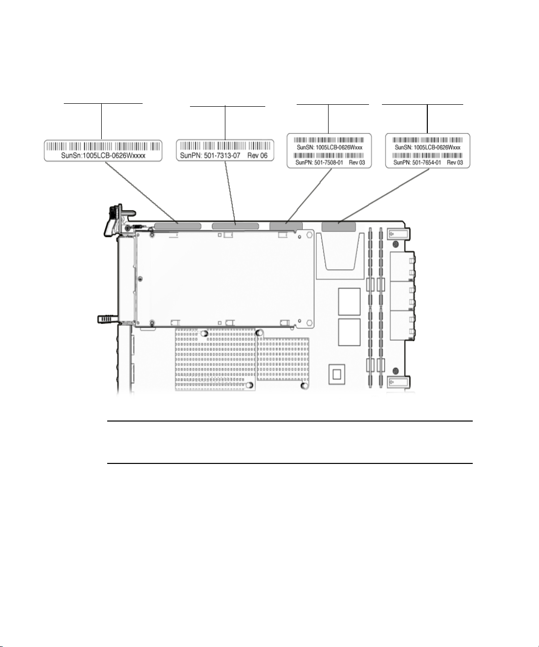
FIGURE 1-6 Sun Netra CP3060 Blade Server Barcode Labeling
Blade Server serial number
Blade Server part number
CPU configuration Memory configuration
Note – You might find the labels shown in FIGURE 1-6 on other locations on your
blade server. Your particular blade server configuration might also appear different
from the illustration.
1-14 Netra CP3060 Board User’s Guide • April 2009

CHAPTER
2
Hardware Installation
This chapter describes the hardware installation procedures for the Sun Netra
CP3060 blade server, and contains the following sections:
■ Section 2.1, “Equipment and Operator Safety” on page 2-1
■ Section 2.2, “Materials and Tools Required” on page 2-2
■ Section 2.3, “Preparing for the Installation” on page 2-3
■ Section 2.4, “Configuring the Blade Server Hardware” on page 2-5
■ Section 2.5, “Installing the Sun Netra CP3060 Blade Server” on page 2-11
■ Section 2.6, “Connecting External I/O Cables” on page 2-17
2.1 Equipment and Operator Safety
Refer to Important Safety Information for Sun Hardware Systems (816-7190) for general
safety information.
Read the safety statements specific to the Sun Netra CP3060 blade server carefully
before you install or remove any part of the system.
Caution – Depending on the particular chassis design, operations with open
equipment enclosures can expose the installer to hazardous voltages with a
consequent danger of electric shock. Ensure that line power to the equipment is
disconnected during operations that make high voltage conductors accessible.
The installer must be familiar with commonly accepted procedures for integrating
electronic systems and with the general practice of Sun systems integration and
administration. Although parts of these systems are designed for hot-swap
2-1

operation, other components must not be subjected to such stresses. Work with
power connected to a chassis only when necessary, and follow these installation
procedures to avoid equipment damage.
This equipment is sensitive to damage from electrostatic discharge (ESD) from
clothing and other materials. Use the following antistatic measures during an
installation:
■ If possible, disconnect line power from the equipment chassis when servicing a
system or installing a hardware upgrade. If the chassis cannot be placed upon a
grounded antistatic mat, connect a grounding strap between the facility electrical
input ground (usually connected to the equipment chassis) and facility electrical
service ground.
■ Use an antistatic wrist strap when:
■ Removing a blade server from its antistatic bag
■ Connecting or disconnecting blade servers or peripherals
The other end of the strap lead should be connected to one of the following:
■ A ground mat
■ Grounded chassis metalwork
■ A facility electrical service ground
■ Keep blade servers in the antistatic bags until they are needed.
■ Place circuit blade servers that are out of their antistatic bags on an antistatic mat
if one is available. The mat must be grounded to a facility electrical service
ground. Do not place blade servers on top of an antistatic bag unless the outside
of the bag also has antistatic protective properties.
■ Remove a blade server from its antistatic bag only when wearing a properly
connected ground strap.
2.2 Materials and Tools Required
This section provides information on the materials and tools required to perform
installation. The minimum tools required to perform installation are:
■ Phillips screwdrivers, No. 1, No. 2 (optional)
■ Antistatic wrist strap
■ Terminal console
See Section 1.5.1, “Hardware Requirements” on page 1-12 for information on
hardware requirements.
2-2 Netra CP3060 Board User’s Guide • April 2009

2.3 Preparing for the Installation
Read the following subsections before starting to install these blade servers. In
addition, do the following:
1. Become familiar with the contents of the referenced documentation.
2. Verify that all listed hardware and software is available (see Section 1.5, “System
Requirements” on page 1-11).
3. Check power, thermal, environmental, and space requirements (see Section 2.3.1,
“Checking Power, Thermal, Environmental, and Space Requirements” on
page 2-3).
4. Verify that local area network (LAN) preparations are completed (see
Section 2.3.2, “Determining Local Network IP Addresses and Host Names” on
page 2-4).
5. Ensure that the host names and their network IP addresses are allocated and
registered at the site.
2.3.1 Checking Power, Thermal, Environmental, and Space Requirements
Verify that you meet the following requirements:
■ Your enclosure specifications support the sum of the specified maximum blade
server power loads. See Section 5.3, “Power” on page 5-27 for blade server power
specifications.
■ Facility power loading specifications can support the rack or enclosure
requirements.
■ Your enclosure specifications support the cooling airflow requirements. The Sun
Netra CP3060 blade server fits a standard ATCA shelf or chassis. If your
installation requirements are different, contact your field application engineer.
Chapter 2 Hardware Installation 2-3

2.3.2 Determining Local Network IP Addresses and Host Names
Collect the following information to connect hosts to the local area network (LAN).
Ask your network administrator for help, if necessary. You can use
record this information. This information is not needed for a standalone installation.
TABLE 2-1 Local Network Information
Information Needed Your Information
IP address*and host name for each Sun
Netra CP3060 client
Domain name
Type of name service and corresponding
name server names and IP addresses—for
example, DNS and NIS (or NIS+)
Subnet mask
Gateway router IP address
NFS server names and IP addresses
Web server URL
* Local IP addresses are not needed if they are assigned by a network DHCP server.
TABLE 2-1 to
You might need the MAC (Ethernet) addresses of the local hosts to make nameserver
database entries. The MAC address can be seen in the console output while booting
to the ok prompt. It can also be derived from the host ID seen on the barcode label
(see Section 1.6.1, “Blade Server Part Number, Serial Number, and Revision Number
Identification” on page 1-13).
2.3.3 Installation Procedure Summary
The steps in this section summarize the Sun Netra CP3060 blade server installation
at a high level. Be sure to read the details in Section 2.4, “Configuring the Blade
Server Hardware” on page 2-5 before installing the blade server.
The procedure to set up and configure a Sun Netra CP3060 blade server in a system
includes the following steps:
1. Configure the blade server’s physical hardware. For example, install memory or
Compact Flash, as necessary.
2. Configure the rear transition module (RTM), as necessary.
2-4 Netra CP3060 Board User’s Guide • April 2009

3. Optional - Physically install the Sun Netra CP3060 RTM into the chassis.
4. Physically install the Sun Netra CP3060 blade server into the chassis.
5. Connect the nodes to a local network. Alternatively, the blade server can be run as
a standalone system without a network connection.
6. Optional - Install an AMC module on the Sun Netra CP3060 blade server.
7. Install the operating system and patches, as necessary. See Section 3.1, “Operating
Systems and Patches” on page 3-1.
2.4 Configuring the Blade Server Hardware
This section lists hardware installation and settings that might apply to your blade
server configuration. Read and perform the procedures, as necessary, before
installing the Sun Netra CP3060 blade server into the chassis.
2.4.1 Installation of DDR-2 DIMM Memory Modules
The Sun Netra CP3060 blade server supports a total of 8 DIMMs and a maximum
memory capacity of 16 Gbytes (using eight 2-Gbyte DIMMs).
location of the DIMMs. In addition to the on-board memory, the Sun Netra CP3060
blade server accommodates the following:
■ Eight standard DDR-2 DIMMs, buffered, and registered
■ 1-Gbyte and 2-Gbyte DDR-2 modules supported
■ DIMMs are installed as shown in FIGURE 2-1
FIGURE 2-1 shows the
Note – You cannot mix 1-Gbyte and 2-Gbyte DIMMs.
The Sun Netra CP3060 blade server supports DDR-2 DIMM memory modules that
have the following characteristics:
■ Each DIMM has a 72-bit-wide data bus (64+8 ECC) and up to 14 address bits.
■ Maximum height of the DIMM module is 0.72 inches, Very Low Profile (VLP).
■ Supports single-bank or dual-bank SDRAM DIMMs.
■ Memory controller supports 128-bit data plus 9-bit error-correcting code (ECC).
■ Maximum of 16 Gbytes.
Chapter 2 Hardware Installation 2-5

For additional information, see Section 5.1.2, “DDR-2 Memory Subsystem” on
page 5-7.
FIGURE 2-1 DDR-2 DIMM Memory Locations
FIGURE 2-1 shows the location of the DIMMs.
DIMM0DIMM1
DIMM5 DIMM4 DIMM12 DIMM13 DIMM8 DIMM9
Note: Channels 1 and 2 are used in four DIMM configurations.
Channels 0 and 3 are only used in eight DIMM configurations.
2-6 Netra CP3060 Board User’s Guide • April 2009
(Channel 2)(Channel 1) (Channel 3)(Channel 0)

2.4.1.1 Installing a DDR-2 DIMM Memory Module
The following procedure provides a general guide for installing additional memory.
However, for directions on the installation process of the memory DDR-2 DIMMs on
the Sun Netra CP3060 blade server, refer to the documentation that shipped with the
memory module.
Caution – Do not remove the DDR-2 DIMM from its antistatic container until you
are ready to install it on the card. Handle the module only by its edges. Do not touch
module components or metal parts. Always wear a grounded antistatic wrist strap
when handling modules.
1. Locate the DDR-2 DIMM connectors on the Sun Netra CP3060 blade server.
Select the connectors where you will install the memory module (see
If you need to replace an existing memory module with a new module, see
Section 2.4.1.2, “Removing a DDR-2 DIMM Memory Module” on page 2-8 for
instructions on removing the DDR-2 DIMM module.
2. Remove the DDR-2 DIMM from its protective packaging, holding the module
only by the edges.
3. Insert the bottom edge of the DDR-2 DIMM into the bottom of the slot’s
hinge-style connector (see
The socket and module are both keyed, which means the module can be installed
one way only. With even pressure, push simultaneously on both upper corners of
the DDR-2 DIMM until its bottom edge (the edge with the gold fingers) is firmly
seated in the connector.
FIGURE 2-2).
FIGURE 2-1).
Chapter 2 Hardware Installation 2-7

FIGURE 2-2 Installing a DDR-2 DIMM Memory Module
Caution – Do not rock the DDR-2 DIMM into place. Ensure that all contacts engage
at the same time. You will feel or hear a click when the DDR-2 DIMM properly seats
in the connector.
4. Press the top edge of the DDR-2 DIMM toward the blade server until the
retainer clips click into place (see
FIGURE 2-2).
The small retainer clips on each side of the DDR-2 DIMM slot click into place in
the notches on the sides of the DDR-2 DIMM.
2.4.1.2 Removing a DDR-2 DIMM Memory Module
You might need to remove a DDR-2 DIMM module from the Sun Netra CP3060
blade server if you are returning the DDR-2 DIMM module or the blade server for
service, or if you are replacing a module with another DDR-2 DIMM module.
Note – Safely store the original factory-shipped DDR-2 DIMM and related DDR-2
DIMM packaging. You might wish to store any removed DDR-2 DIMM in the new
DDR-2 DIMM packaging, or use the packaging for service.
To remove a DDR-2 DIMM from the Sun Netra CP3060 blade server, perform the
following steps:
1. Take antistatic precautions: attach and electrically ground the wrist strap.
2-8 Netra CP3060 Board User’s Guide • April 2009

Caution – Always wear a grounded antistatic wrist strap when handling modules.
2. Place the Sun Netra CP3060 blade server on an antistatic mat, or on the blade
server’s antistatic bag if you do not have a mat available.
3. For the DDR-2 DIMM you wish to remove, simultaneously pull both DDR-2
DIMM retainer clips outward from the slot.
4. Grasp the DDR-2 DIMM by the edges, and carefully pull it out of its connector.
Place it in an antistatic bag.
FIGURE 2-3 Removing a DDR-2 DIMM Memory Module
5. If you are replacing the module you removed with a new DDR-2 DIMM, install
it as described in Section 2.4.1.1, “Installing a DDR-2 DIMM Memory Module” on
page 2-7.
2.4.2 Installation of Optional Compact Flash Card
An optional IDE Compact Flash card can be installed on the Sun Netra CP3060 blade
server. The Compact Flash card is not hot-swappable and there is no access to the
card once the blade server is installed in an ATCA chassis.
Chapter 2 Hardware Installation 2-9

To install the Compact Flash card, use the arrow on the card’s label as a guide and
insert the card into the Compact Flash connector (see
FIGURE 2-4 Compact Flash Card Connector
FIGURE 2-4).
Compact Flash connector
2.4.3 Configuring Rear Transition Module Hardware
If you are using the Sun Netra CP3060 RTM, refer to the Sun Netra CP3060 Rear
Transition Module User’s Guide (819-6689). You can also refer to the Sun Netra CP3060
RTM manual for detailed connector pin assignments.
2-10 Netra CP3060 Board User’s Guide • April 2009

2.5 Installing the Sun Netra CP3060 Blade Server
If you are installing the Sun Netra CP3060 blade server with the RTM, first install the
RTM at the rear of the server. Then install the node card in the front of the server.
Even though you will be installing the RTM first, look at the front of the server and
locate the slot number where you will be installing the Sun Netra CP3060 blade
server. Then go to the back of the server and install the RTM in that particular slot.
2.5.1 Installing the Sun Netra CP3060 Blade Server With a Rear Transition Module
A compatible RTM must be used with the Sun Netra CP3060 blade server for rear
I/O access. The RTM enables access to the network, to a boot device, and to a
console terminal. You can use the Sun Netra CP3060 RTM, or you might design your
own rear transition module.
Chapter 2 Hardware Installation 2-11

FIGURE 2-5 Installing the Sun Netra CP3060 Rear Transition Module
Zone 3
connectors
Netra CP3060 blade server
(installed from front)
Netra CP3060 RTM
(installed from rear)
ATCA chassis midplane
2.5.1.1 Installing a Rear Transition Module
1. Verify that you have taken the necessary antistatic precautions.
2. Go to the rear of the system and choose an appropriate slot for the RTM.
RTMs must be installed inline behind the accompanying node blade server. For
example, if the accompanying node blade server is installed in slot 3, its RTM
must be installed at the back of the system in slot 3. See
2-12 Netra CP3060 Board User’s Guide • April 2009
FIGURE 2-5.
3. Remove the slot filler panel from the selected node blade server slot, if
necessary.
4. Get the RTM from the shipping kit.
5. Perform any card-specific hardware procedures, if necessary.
Refer to the documentation that you received with the card for more information.
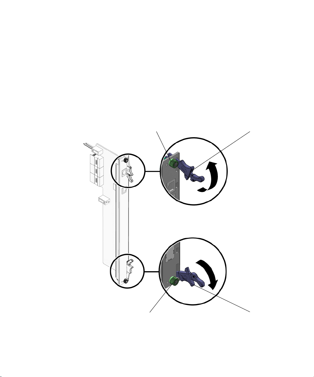
6. Prepare the card by opening the injector/ejector latches at the top and bottom of
the card (
FIGURE 2-6 RTM Injector/Ejector Latch and Locking Screw
FIGURE 2-6).
Locking screw
Injector/ejector latch
Locking screw
Injector/ejector latch
Chapter 2 Hardware Installation 2-13

7. Carefully align the edges of the card with the card guides in the appropriate
slot.
It might be helpful to look into the enclosure to verify correct alignment of the
rails in the guides.
8. Taking care to keep the blade server aligned in the guides, slide the card in
until the injector/ejector latches engage the card cage.
9. Push the blade server into the midplane connectors and close the latches to seat
the blade server in the connectors.
10. Tighten the locking screws to ensure that the blade server is secured into the
shelf.
11. Install the Sun Netra CP3060 blade server into the shelf.
Go to Section 2.5.2, “Installing the Sun Netra CP3060 Blade Server” on page 2-15
for those instructions.
2.5.2 Installing the Sun Netra CP3060 Blade Server
1. If you have installed a Sun Netra CP3060 RTM, go to the front of the system
and locate the card slot where you installed the RTM at the rear of the system.
2. Remove the filler panel, if necessary.
The filler panel is secured to the card cage using two screws, one at the top of the
filler panel, the other at the bottom. Store the filler panel in a safe place; you
might need to use it again if you have to remove a card for an extended period of
time.
3. Prepare the blade server by opening the injector/ejector latches (
4. Carefully align the edges of the blade server with the card guides in the
appropriate slot (
It might be helpful to look into the enclosure to verify correct alignment of the
rails in the guides.
5. Taking care to keep the blade server aligned in the guides, slide the blade
server in until the injector/ejector latches engage the card cage.
2-14 Netra CP3060 Board User’s Guide • April 2009
FIGURE 2-7).
FIGURE 2-6).

FIGURE 2-7 Installing Node Blade Server Into Chassis Slot
6. Taking care to keep the blade server aligned in the guides, slide the blade
server in until the injector/ejector latches engage the card cage.
7. Push the blade server slightly into the midplane connectors, and then close the
latches to seat the blade server in the connectors (
FIGURE 2-8).
When the lower latch is closed, the blue Hot-Swap LED blinks while the blade
server is initializing. The blue LED turns off and the green OK LED lights when
the blade server is ready.
Chapter 2 Hardware Installation 2-15

FIGURE 2-8 Sun Netra CP3060 Blade Server Latches and Locking Screws
Locking screw
Bottom hot-swap
/
latch
Top latch
Locking screw
8. Tighten the locking screws to ensure the blade server is secured into the shelf
(see
FIGURE 2-6).
2.6 Connecting External I/O Cables
External I/O cables are connected to the Sun Netra CP3060 blade server, or to the
Sun Netra CP3060 RTM when a rear transition module is used. Information on
connecting each of these cables follows:
■ For Ethernet connections, category 5e or better network cable is required. One
end of the Ethernet cable is connected to a suitable 10/100/1000BASE-T switch
and the other end to one of the Ethernet ports on the Sun Netra CP3060 blade
server. Both Ethernet ports A and B are available on the Sun Netra CP3060 blade
server front panel.
2-16 Netra CP3060 Board User’s Guide • April 2009

Note – A single 10/100BASE-T Ethernet port is also available on the Sun Netra
CP3060 RTM when installed.) Refer to the Sun Netra CP3060 Rear Transition Module
User’s Guide (819-6689) for more information.
Use the bge device names shown in
TABLE 2-2 when configuring the Ethernet
ports.
TABLE 2-2 bge Device Names
Ethernet Ports Solaris 10 OS
Ethernet Port A (on front panel) and
Ethernet port on the RTM
Ethernet Port B (on front panel) e1000g1
■ An asynchronous serial I/O cable can be attached from serial communication
e1000g0
devices to the RJ-45 serial port on the Sun Netra CP3060 blade server’s front
panel.
Note – A serial port is also provided on the Sun Netra CP3060 RTM. Either the
serial port on the Sun Netra CP3060 blade server or the serial port on Sun Netra
CP3060 RTM can be used, but only one of the ports should be used at one time.
Once a serial cable is connected, use the tip utility on the host to establish a
full-duplex terminal connection with the Sun Netra CP3060 blade server. At the
UNIX prompt in a command tool or shell tool, type:
TABLE 2-3
# tip -9600 /dev/ttya (for serial port)
2.7 Installation of Optional AMC Modules
An Advanced Mezzanine card (AMC) is a card or module that provides additional
functionality to the Sun Netra CP3060 blade server. The blade server contains one
AMC slot in which you can install an optional AMC device (see
location of these slots). The AMC device can be installed and removed via a cutout
in the front panel while the Sun Netra CP3060 blade server is installed in the chassis.
Chapter 2 Hardware Installation 2-17
FIGURE 2-1 for the

2.7.0.1 Installing an Optional AMC Module
Note – The following procedure provides a general set of instructions for installing
AMC modules on the Sun Netra CP3060 blade server. Refer to the AMC module
manufacturer’s documentation for specific instructions on installing these devices.
1. Retrieve the wrist strap from the adapter’s shipping kit.
2. Attach the adhesive copper strip of the antistatic wrist strap to the metal
chassis. Wrap the other end twice around your wrist, with the adhesive side
against your skin.
3. Remove the AMC slot filler panel from the blade server’s front panel.
(
FIGURE 2-9).
FIGURE 2-9 Removing AMC Slot Filler Panel
AMC slot filler panel
4. Retrieve the AMC module from its shipping kit and place it on an antistatic
surface.
5. Insert the AMC module through the cutout and into the AMC slot (
2-18 Netra CP3060 Board User’s Guide • April 2009
FIGURE 2-10).

FIGURE 2-10 Inserting AMC Module Into AMC Connector
AMC module
(AMC disk drive shown)
6. Carefully plug the AMC module into the AMC connector (FIGURE 2-10).
Ensure that the AMC module is seated correctly in the connector.
Caution – Do not use excessive force when installing the AMC module into the slot.
You might damage the AMC connector on the Sun Netra CP3060 blade server,
causing permanent damage to the AMC module or the blade server. If the AMC
module does not seat properly when you apply even pressure, remove the AMC
module and carefully reinstall it.
7. Refer to the AMC module documentation for software and cabling installation
instructions.
Chapter 2 Hardware Installation 2-19

2-20 Netra CP3060 Board User’s Guide • April 2009

Chapter 2 Hardware Installation 2-21

CHAPTER
3
Software Installation
This chapter contains the following sections:
■ Section 3.1, “Operating Systems and Patches” on page 3-1
■ Section 3.2, “Firmware Updates” on page 3-2
■ Section 3.3, “Mandatory /etc/system File Entry” on page 3-2
■ Section 3.4, “Installing Diskless Clients” on page 3-3
■ Section 3.5, “Downloading and Installing SunVTS Software” on page 3-7
3.1 Operating Systems and Patches
The Sun Netra CP3060 blade server supports the Solaris 10 6/06 OS and subsequent
compatible versions, with supported Netra patches. The Solaris OS software can be
downloaded from the Sun download center at:
http://www.sun.com/download
Note – Refer to the Sun Netra CP3060 Blade Server Product Notes (819-4966) for
information on the Netra patches at http://www.sun.com/documentation.
For information on these versions of the Solaris OS, including installation, see the
appropriate Solaris Documentation Collection at the Sun Documentation web site at:
http://www.sun.com/documentation
3-1

3.2 Firmware Updates
The Sun Netra CP3060 firmware updates can be downloaded from the Sun
download center at:
http://www.sun.com/download
Note – For information on firmware updates, refer to the Sun Netra CP3060 Blade
Server Product Notes (819-4966) which are available online at
http://www.sun.com/documentation.
3.3 Mandatory /etc/system File Entry
A mandatory entry must be listed in the /etc/system file to ensure the optimal
functionality of the blade server.
The following entry must be in the /etc/system file:
set pcie:pcie_aer_ce_mask=0x1
Check that the entry is present before deploying the blade server.
▼ To Check and Create the Mandatory
/etc/system File Entry
1. Log in as superuser.
3-2 Netra CP3060 Board User’s Guide • April 2009

2. Check the /etc/system file to see if the mandatory line is present.
TABLE 3-1
# more /etc/system
*ident "@(#)system 1.18 05/06/27 SMI" /* SVR4 1.5 */
*
* SYSTEM SPECIFICATION FILE
.
.
.
set pcie:pcie_aer_ce_mask=0x1
.
3. If the entry is not there, add it.
Use an editor to edit the /etc/system file and add the entry.
4. Reboot the server.
3.4 Installing Diskless Clients
The following procedures describe how to create a boot server for diskless clients
and how to add new diskless clients to the patched boot server. For additional
instructions on installing diskless clients, refer to the appropriate Solaris
Documentation Collection at the Sun Documentation web site at:
http://www.sun.com/documentation
You must have a superuser password on your diskless server to perform the
following tasks.
3.4.1 Creating a Boot Server for Diskless Clients
Note – This procedure sets up a boot server by starting the operating environment
services required for diskless clients. Once you have set up the boot server, see
Section 3.4.2, “Adding a Diskless Client” on page 3-5 for instructions on adding
diskless clients to the boot server.
1. Verify that the IP addresses for all other network interfaces on the boot server
have corresponding hostnames in the hosts database.
Chapter 3 Software Installation 3-3

2. Log in to the network server as superuser and change to the /usr/sadm/bin
directory.
TABLE 1
# cd /usr/sadm/bin
3. Use the smosservice command to add boot services to the installation server.
Note – The following command is a single long entry. Do not press the Return key
until you have typed the entire text string shown in the following command.
TABLE 2
# ./smosservice add -u root -p root_password -- -x mediapath=image_directory
-x platform=sparc.sun4v.Solaris_n -x cluster=SUNWCXall -x locale=locale
Where:
■ root_password is the root password for the installation server
■ image_directory is the path to the directory where the Solaris install image is stored
■ N is the Solaris OS version you are using.
■ locale is the locale that you want to use
Refer to the smosservice(1M) man page for more information and options.
For example:
TABLE 3
# ./smosservice add -u root -p root_password -- -x mediapath=/export/install
-x platform=sparc.sun4v.Solaris_10 -x cluster=SUNWCXall -x locale=en_US
Where:
■ root_password = root_password
■ image_directory = /export/install
■ locale = en_US
■ n = 10 (for Solaris 10)
3-4 Netra CP3060 Board User’s Guide • April 2009

4. Download and install additional patches.
Refer to the Sun Netra CP3060 Blade Server Product Notes (819-4966) for the latest
information on the patches available for the Sun Netra CP3060 blade server. The
document can be downloaded from the following web site:
http://www.sun.com/documentation
Follow the instructions in the Sun Netra CP3060 Blade Server Product Notes
(819-4966) for downloading and applying patches to a diskless clients boot server.
5. After the patches are installed, follow the procedure in Section 3.4.2, “Adding a
Diskless Client” on page 3-5.
3.4.2 Adding a Diskless Client
1. Prepare a patched boot server for the diskless clients.
Follow the steps in Section 3.4.1, “Creating a Boot Server for Diskless Clients” on
page 3-3 to create a boot server for the diskless clients.
2. Log in to the patched boot server as superuser.
3. Collect the following information for the diskless client you are adding:
■ Client’s IP address
■ Client’s Ethernet address
■ Client’s host name
4. Change directories to the /usr/sadm/bin directory.
TABLE 4
# cd /usr/sadm/bin
5. Set up the diskless clients.
For each diskless client, type the following command as superuser:
TABLE 5
# ./smdiskless add -- -i ip_address -e ethernet_address -n host_name\
-x os=sparc.sun4v.Solaris_n -x root=/export/root/host_name \
-x swap=/export/swap/host_name -x swapsize=swap_size -x tz=time_zone \
-x locale=locale -x ns=name_service -x nameserver=name_server
Where:
■ ip_address is the client’s IP address
■ ethernet_address is the client’s Ethernet address
Chapter 3 Software Installation 3-5

■ host_name is the client’s host name
■ n is the Solaris OS version you are using, either 10 or 9.
■ swap_size is the size of the swap space that you will be using. The default is 24,
however your swap space should be the same amount as your memory
■ time_zone is the client’s time zone
■ locale is the client’s locale
■ name_service is the client’s nameservice
■ name_server is the nameserver’s hostname
Refer to the smdiskless(1M) man page for more information and options.
For example:
TABLE 6
# ./smdiskless add -- -i 129.144.214.999 -e 8:0:20:22:b3:aa -n client_host -x
os=sparc.sun4v.Solaris_10 -x root=/export/root/client_host -x swap=
/export/swap/client_host -x swapsize=999 -x tz=US/Pacific -x locale=en_US -x
ns=NIS -x nameserver=nameserver_host
Where:
■ ip_address = 129.144.214.999
■ ethernet_address = 8:0:20:22:b3:aa
■ host_name = client_host
■ n = 10 (for Solaris 10)
■ swap_size = 128
■ time_zone = US/Pacific
■ locale = en_US
■ name_service = NIS
■ name_server = nameserver_host
3-6 Netra CP3060 Board User’s Guide • April 2009

You must type your superuser password again after typing this command. The
installation process should take roughly 5 minutes per client and about 15-30
minutes for the operating environment service to install; however, no progress is
displayed on screen while the process is running. Do not cancel or kill the process
until the process has successfully completed.
You should see messages similar to the following after a few moments,
confirming that the command went through successfully the second time:
TABLE 7
Login to client_host as user root was successful.
Download of com.sun.admin.osservermgr.cli.OsServerMgrCli from client_host was
successful.
6. Boot the diskless client.
3.5 Downloading and Installing SunVTS Software
SunVTS™ software is a comprehensive suite that tests and validates the Sun Netra
CP3060 blade server by verifying the configuration and function of most hardware
controllers and devices on the blade server. SunVTS software is used to validate a
system during development, production, inspection, troubleshooting, periodic
maintenance, and system or subsystem stressing. SunVTS software can be tailored to
run on machines ranging from desktops to servers with modifiable test instances
and processor affinity features.
You can perform high-level system testing by using the appropriate version of
SunVTS software. For detailed information on SunVTS support and downloads,
refer to the following web site:
http://www.sun.com/oem/products/vts/
Ensure that the SunVTS software version is compatible with the Solaris OS version
being used. Information on the version of the SunVTS software installed can be
found in the file:
/opt/SUNWvts/bin/.version
For the latest version of SunVTS document, go to:
http://www.sun.com/documentation
Chapter 3 Software Installation 3-7

Note – For security reasons, only a superuser is permitted to run SunVTS software.
Installation and starting instructions are included with the software when it is
downloaded.
3-8 Netra CP3060 Board User’s Guide • April 2009

CHAPTER
4
Firmware and Blade Server Management
This chapter contains the following sections:
■ Section 4.1, “System Firmware” on page 4-1
■ Section 4.2, “Power-On Self-Test Diagnostics” on page 4-2
■ Section 4.3, “OpenBoot Firmware” on page 4-3
■ Section 4.4, “Error Handling Summary” on page 4-12
■ Section 4.5, “Automatic System Recovery” on page 4-13
■ Section 4.6, “Hot-Swap Information” on page 4-15
■ Section 4.7, “Network Device Aliases” on page 4-17
■ Section 4.8, “Retrieving Device Information” on page 4-17
4.1 System Firmware
The Sun Netra CP3060 blade server contains a modular firmware architecture that
gives you latitude in controlling boot initialization. You can customize the
initialization, test the firmware, and even enable the installation of a custom
operating system.
This platform also employs the Intelligent Platform Management controller
(IPMC)—described in Section 5.1.6, “Intelligent Platform Management Controller”
on page 5-19—which controls the system management, hot-swap control, and some
blade server hardware. The IPMC configuration is controlled by separate firmware.
The Sun Netra CP3060 blade server boots from the 4-Mbyte system flash PROM
device that includes the power-on self-test (POST) and OpenBoot™ firmware.
4-1

4.2 Power-On Self-Test Diagnostics
Power-on self-test (POST) is a firmware program that helps determine whether a
portion of the system has failed. POST verifies the core functionality of the system,
including the CPU modules, motherboard, memory, and some on-board I/O devices.
The software then generates messages that can be useful in determining the nature
of a hardware failure. POST can run even if the system is unable to boot.
If POST detects a faulty component, it is disabled automatically, preventing faulty
hardware from potentially harming any software. If the system is capable of running
without the disabled component, the system boots when POST is complete. For
example, if one of the processor cores is deemed faulty by POST, the core is disabled,
and the system boots and runs using the remaining cores.
POST diagnostic and error message reports are displayed on a console.
4.2.1 POST Test Coverage
The POST diagnostics include the following tests:
1. UltraSPARC T1 Processor Tests:
• MMU (Memory Management Unit), all cores
• DMMU TLBs: tags, data RAM tests
• IMMU TLBs: tags, data RAM tests
• Caches, all cores
• L2 Cache
• L1 Icache
• L1 Dcache
• FPU (Floating Point Unit
• Functional
• Register
• Interrupts
2. Memory Tests (up to 2-Gbyte/DIMM):
• SDRAM data line test
• SDRAM address line test
• SDARM cell integrity Test
• MOVing inversions memory test
3. POST Image Tests
• POST PROM checksum test
• POST memory checksum test
4. ECC Error Test
4-2 Netra CP3060 Board User’s Guide • April 2009

5. XBUS SRAM Test
6. JBus-to-PCIE Bridge Tests:
• Internal registers test JBus interrupts
• JBus interrupts
• PCI-E MSI Interrupts test
• PLX Interconnect test
• PCI DMA tests
• JBus-to-PCI-E loop-back test
7. PCIE Tests:
• Verify PCI-E Bus configuration
• Verify VID/DIC registers for all onboard PCI device
• Verify link status of all onboard PCI-E channel
4.2.2 POST Diagnostic and Error Message Format
POST diagnostic and error messages are displayed on a console. The format of the
these messages is the following:
Core-ID:Strand-ID ERROR: TEST = test-name
Core-ID:Strand-ID H/W under test = description
Core-ID:Strand-ID Repair Instruction
Core-ID:Strand-ID MSG = error-message-body
Core-ID:Strand-ID END_ERROR
The following is an example of a POST error message
TABLE 4-1
3:2>ERROR: TEST = L2-Cache Functional
3:2>H/W under test = Core l2 Cache
3:2>Repair Instructions: Replace items in order listed by ’H/W
under test’ above.
3:2>MSG = No way found to match tag address 00000000.00600000,
state 3
3:2>END_ERROR
4.3 OpenBoot Firmware
The Solaris OS installed operates at different run levels. For a full description of run
levels, refer to the Solaris system administration documentation.
Chapter 4 Firmware and Blade Server Management 4-3

Most of the time, the OS operates at run level 2 or run level 3, which are multiuser
states with access to full system and network resources. Occasionally, you might
operate the system at run level 1, which is a single-user administrative state.
However, the lowest operational state is run level 0.
When the OS is at run level 0, the ok prompt appears. This prompt indicates that the
OpenBoot™ firmware is in control of the system.
There are a number of scenarios under which OpenBoot firmware control can occur.
By default, before the operating system is installed the system comes up under
OpenBoot firmware control.
■ When the auto-boot? OpenBoot configuration variable is set to false, the system
boots to the ok prompt.
■ When the operating system is halted, the system transitions to run level 0 in an
orderly way.
■ When the operating system crashes, the system reverts to OpenBoot firmware
control.
■ During the boot process, when there is a serious hardware problem that prevents
the operating system from running, the system reverts to OpenBoot firmware
control.
■ When a serious hardware problem develops while the system is running, the
operating system transitions smoothly to run level 0.
■ When the OS is deliberately placed under the OpenBoot firmware control in order
to execute firmware-based commands.
4.3.1 Getting to the ok Prompt
There are different ways of reaching the ok prompt. The methods are not equally
desirable. See
TABLE 4-2 Ways of Accessing the ok Prompt
Access Method What to Do
Graceful shutdown of
the Solaris OS
Manual system reset Setting the OBP auto-boot variable to false causes the system
4-4 Netra CP3060 Board User’s Guide • April 2009
TABLE 4-2 for details.
From a shell or command tool window, issue an appropriate
command (for example, the shutdown or init command) as
described in Solaris system administration documentation.
to stop at the ok? prompt the next time the blade server is reset.

Caution – Obtaining the ok prompt suspends all application and operating system
software. After you issue firmware commands and run firmware-based tests from
the ok prompt, the system might not be able to resume where it left off.
If possible, back up system data before starting accessing the ok prompt. Also exit or
stop all applications, and warn users of the impending loss of service. For
information about the appropriate backup and shutdown procedures, see Solaris
system administration documentation.
4.3.2 Auto-Boot Options
The system firmware stores a configuration variable called auto-boot?, which
controls whether the firmware will automatically boot the operating system after
each reset. The default setting for Sun platforms is true.
Normally, if a system fails power-on diagnostics, auto-boot? is ignored and the
system does not boot unless an operator boots the system manually. An automatic
boot is generally not acceptable for booting a system in a degraded state. Therefore,
the Sun Netra CP3060 server OpenBoot firmware provides a second setting,
auto-boot-on-error?. This setting controls whether the system will attempt a
degraded boot when a subsystem failure is detected. Both the auto-boot? and
auto-boot-on-error? switches must be set to true to enable an automatic
degraded boot. To set the switches, type:
ok setenv auto-boot? true
ok setenv auto-boot-on-error? true
Note – The default setting for auto-boot-on-error? is false. The system will
not attempt a degraded boot unless you change this setting to true. In addition, the
system will not attempt a degraded boot in response to any fatal nonrecoverable
error, even if degraded booting is enabled. For examples of fatal nonrecoverable
errors, see “OpenBoot Configuration Variables” on page 9.
4.3.3 OpenBoot Commands
You type the OpenBoot commands at the ok prompt. Two of the OpenBoot
commands that can provide useful diagnostic information include:
■ probe-ide
Chapter 4 Firmware and Blade Server Management 4-5

■ show-devs
For a complete list of OpenBoot commands and more information about the
OpenBoot firmware, refer to the OpenBoot 4.x Command Reference Manual. An online
version of the manual is included with the OpenBoot Collection AnswerBook that
ships with Solaris software.
4.3.3.1 probe-ide Command
The probe-ide command communicates with all Integrated Drive Electronics (IDE)
devices connected to the IDE bus. This is the internal system bus for media devices
such as the DVD drive.
Caution – If you used the halt command or the Stop-A key sequence to reach the
ok prompt, issuing the probe-ide command can hang the system.
CODE EXAMPLE 4-2 shows sample output from the probe-ide command.
CODE EXAMPLE 4-1 probe-ide Command Output
{0} ok probe-ide
Device 0 ( Primary Master )
ATA Model: FUJITSU MHV2040BH
Device 1 ( Primary Slave )
ATA Model:
Device 2 ( Secondary Master )
Not Present
Device 3 ( Secondary Slave )
Not Present
4.3.3.2 show-devs Command
The show-devs command lists the hardware device paths for each device in the
firmware device tree.
CODE EXAMPLE 4-2 show-devs Command Output
{o} ok show-devs
/pci@7c0
/pci@780
/cpu@17
4-6 Netra CP3060 Board User’s Guide • April 2009
CODE EXAMPLE 4-2 shows some sample output.

CODE EXAMPLE 4-2 show-devs Command Output (Continued)
/cpu@16
/cpu@15
/cpu@14
/cpu@13
/cpu@12
/cpu@11
/cpu@10
/cpu@f
/cpu@e
/cpu@d
/cpu@c
/cpu@b
/cpu@a
/cpu@9
/cpu@8
/cpu@7
/cpu@6
/cpu@5
/cpu@4
/cpu@3
/cpu@2
/cpu@1
/cpu@0
/virtual-devices@100
/virtual-memory
/memory@m0,800000
/aliases
/options
/openprom
/chosen
/packages
/pci@7c0/network@0,1
/pci@7c0/network@0
/pci@780/pci@0
/pci@780/pci@0/pci@9
/pci@780/pci@0/pci@8
/pci@780/pci@0/pci@2
/pci@780/pci@0/pci@1
/pci@780/pci@0/pci@2/network@0,1
/pci@780/pci@0/pci@2/network@0
/pci@780/pci@0/pci@1/pci@0
/pci@780/pci@0/pci@1/pci@0/ide@1f,1
/pci@780/pci@0/pci@1/pci@0/ide@1f
Chapter 4 Firmware and Blade Server Management 4-7

CODE EXAMPLE 4-2 show-devs Command Output (Continued)
/pci@780/pci@0/pci@1/pci@0/ide@1f,1/cdrom
/pci@780/pci@0/pci@1/pci@0/ide@1f,1/disk
/pci@780/pci@0/pci@1/pci@0/ide@1f/cdrom
/pci@780/pci@0/pci@1/pci@0/ide@1f/disk
/virtual-devices@100/ipmi@f
/virtual-devices@100/flashupdate@e
/virtual-devices@100/led@d
/virtual-devices@100/explorer@c
/virtual-devices@100/sunmc@b
/virtual-devices@100/sunvts@a
/virtual-devices@100/fma@9
/virtual-devices@100/echo@8
/virtual-devices@100/loop@6
/virtual-devices@100/loop@7
/virtual-devices@100/rtc@5
/virtual-devices@100/ncp@4
/virtual-devices@100/console@1
/virtual-devices@100/flashprom@0
/virtual-devices@100/nvram@3
/openprom/client-services
/packages/SUNW,asr
/packages/obp-tftp
/packages/dropins
/packages/terminal-emulator
/packages/disk-label
/packages/deblocker
/packages/SUNW,builtin-drivers
{0} ok
4.3.3.3 Checking Network Using watch-net and watch-net-all Commands
The watch-net diagnostics test monitors Ethernet packets on the primary network
interface. The watch-net-all diagnostics test monitors Ethernet packets on the
primary network interface and on any additional network interfaces connected to
the system blade server. Good packets received by the system are indicated by a
period (.). Errors such as the framing error and the cyclic redundancy check (CRC)
error are indicated with an X and an associated error description.
4-8 Netra CP3060 Board User’s Guide • April 2009

● To start the watch-net diagnostic test, type the watch-net command at the
ok prompt.
{0} ok watch-net
Internal loopback test -- succeeded.
Link is -- up
Looking for Ethernet Packets.
‘.’ is a Good Packet. ‘X’ is a Bad Packet.
Type any key to stop.................................
● To start the watch-net-all diagnostic test, type watch-net-all at the ok
prompt.
{0} ok watch-net-all
/pci@1f,0/pci@1,1/network@c,1
Internal loopback test -- succeeded.
Link is -- up
Looking for Ethernet Packets.
‘.’ is a Good Packet. ‘X’ is a Bad Packet.
Type any key to stop.
4.3.4 OpenBoot Configuration Variables
The OpenBoot configuration variables are stored in the OBP flash PROM and
determine how and when OpenBoot tests are performed. This section explains how
to access and modify OpenBoot configuration variables. For a list of important
OpenBoot configuration variables, see
Changes to OpenBoot configuration variables take effect at the next reboot.
TABLE 4-3 OpenBoot Configuration Variables
Variable Possible Values Default Value Description
local-mac-address? true, false true If true, network drivers use their own
TABLE 4-3.
MAC address, not the server MAC address.
Chapter 4 Firmware and Blade Server Management 4-9

TABLE 4-3 OpenBoot Configuration Variables (Continued)
Variable Possible Values Default Value Description
fcode-debug? true, false false If true, include name fields for plug-in
device FCodes.
scsi-initiator-id 0-15 7 SCSI ID of the Serial Attached SCSI
controller.
oem-logo? true, false false If true, use custom OEM logo; otherwise,
use Sun logo.
oem-banner? true, false false If true, use custom OEM banner.
ansi-terminal? true, false true If true, enable ANSI terminal emulation.
screen-#columns 0-n 80 Sets number of columns on screen.
screen-#rows 0-n 34 Sets number of rows on screen.
ttya-mode 9600,8,n,1,- 9600,8,n,1,- Serial management port (baud rate, bits,
parity, stop, handshake). The serial
management port only works at the default
values.
output-device virtual-conso
virtual-consolePower-on output device.
le, screen
input-device virtual-conso
virtual-consolePower-on input device.
le, keyboard
auto-boot-on-error? true, false false If true, boot automatically after system
error.
load-base 0-n 16384 Address.
auto-boot? true, false true If true, boot automatically after power on
or reset.
network-boot-arguments[protocol,]
[key=value, ]
none Arguments to be used by the PROM for
network booting. Defaults to an empty
string. network-boot-arguments can be
used to specify the boot protocol
(RARP/DHCP) to be used and a range of
system knowledge to be used in the process.
For further information, see the eeprom
(1M) man page or your Solaris Reference
Manual.
boot-command variable-name boot Action following a boot command.
boot-file variable-name none File from which to boot if diag-switch? is
false.
boot-device variable-name disk net Device(s) from which to boot if
diag-switch? is false.
4-10 Netra CP3060 Board User’s Guide • April 2009

TABLE 4-3 OpenBoot Configuration Variables (Continued)
Variable Possible Values Default Value Description
use-nvramrc? true, false false If true, execute commands in NVRAMRC
during server startup.
nvramrc variable-name none Command script to execute if
use-nvramrc? is true.
security-mode none, command,
full
security-password variable-name none Firmware security password if
security-#badlogins variable-name none Number of incorrect security password
verbosity max, min, none,
normal
diag-switch? true, false false If true:
error-reset-recovery boot, none,
sync
none Firmware security level.
security-mode is not none (never
displayed). Do not set this directly.
attempts.
min Controls the amount and detail of OpenBoot
output.
Default is min.
• none
• min
• normal
• max
• After a boot request, boot diag-file from
If false:
• After a boot request, boot boot-file from
boot Specifies recovery action after an error reset.
Default is boot.
• none
• boot
• sync
– Only error and fatal messages are
displayed on the system console.
– Notice, error, warning, and fatal
messages are displayed on the system
console.
– Summary progress and
operational messages are displayed on
the system console in addition to the
messages displayed by the min setting.
– Detailed progress and operational
messages are displayed on the system
console.
diag-device
boot-device
– No recovery action.
– System attempts to boot.
– Firmware attempts to execute a
Solaris sync callback routine.
Chapter 4 Firmware and Blade Server Management 4-11

4.3.4.1 Viewing and Setting OpenBoot Configuration Variables
● Halt the server to display the ok prompt.
■ To display the current values of all OpenBoot configuration variables, use the
printenv command.
The following example shows a short excerpt of this command’s output.
TABLE 4-4
ok printenv
Variable Name Value Default Value
local-mac-address? true true
fcode-debug? false false
scsi-initiator-id 7 7
oem-logo? false false
boot-command boot boot
boot-file
boot-device disk net disk net
use-nvramrc? false false
nvramrc
■ To set or change the value of an OpenBoot configuration variable, use the setenv
command:
TABLE 4-5
ok setenv error-reset-recovery none
error-reset-recovery = none
■ To set OpenBoot configuration variables that accept multiple keywords, separate
keywords with a space.
4.4 Error Handling Summary
Error handling during the power-on sequence falls into one of the following three
cases:
■ If no errors are detected by POST or OpenBoot firmware, the system attempts to
boot if auto-boot? is true.
■ If only nonfatal errors are detected by POST or OpenBoot firmware, the system
attempts to boot if auto-boot? is true and auto-boot-on-error? is true.
Nonfatal errors include the following:
4-12 Netra CP3060 Board User’s Guide • April 2009

■ SATA subsystem failure. In this case, a working alternate path to the boot disk
is required.
■ Ethernet interface failure.
■ Serial interface failure.
■ Memory failure. Given a failed DIMM, the firmware will unconfigure the entire
logical bank associated with the failed module. Another nonfailing logical
bank must be present in the system for the system to attempt a degraded boot.
Note – If POST or OpenBoot firmware detects a nonfatal error associated with the
normal boot device, the OpenBoot firmware automatically unconfigures the failed
device and tries the next-in-line boot device, as specified by the boot-device
configuration variable.
■ If a fatal error is detected by POST or OpenBoot firmware, the system does not
boot regardless of the settings of auto-boot? or auto-boot-on-error?. Fatal
nonrecoverable errors include the following:
■ Any CPU failed
■ All logical memory banks failed
■ Flash RAM cyclical redundancy check (CRC) failure
■ Critical field-replaceable unit (FRU) PROM configuration data failure
■ Critical application-specific integrated circuit (ASIC) failure
4.5 Automatic System Recovery
Automatic system recovery (ASR) consists of self-test features and an
autoconfiguration capability to detect failed hardware components and unconfigure
them. By enabling ASR, the server is able to resume operating after certain nonfatal
hardware faults or failures have occurred.
If a component is monitored by ASR and the server is capable of operating without
it, the server automatically reboots if that component develops a fault or fails. This
capability prevents a faulty hardware component from stopping operation of the
entire system or causing the system to fail repeatedly.
If a fault is detected during the power-on sequence, the faulty component is
disabled. If the system remains capable of functioning, the boot sequence continues.
Chapter 4 Firmware and Blade Server Management 4-13

To support this degraded boot capability, the OpenBoot firmware uses the 1275
client interface (by means of the device tree) to mark a device as either failed or
disabled, creating an appropriate status property in the device tree node. The Solaris
OS does not activate a driver for any subsystem marked in this way.
As long as a failed component is electrically dormant (not causing random bus
errors or signal noise, for example), the system reboots automatically and resumes
operation while a service call is made.
Once a failed or disabled device is replaced with a new one, the OpenBoot firmware
automatically modifies the status of the device upon reboot.
Note – ASR is not enabled until you activate it (see Section 4.5.1.1, “To Enable
Automatic System Recovery” on page 4-14).
4.5.1 Enabling and Disabling Automatic System Recovery
The automatic system recovery (ASR) feature is not activated until you enable it.
Enabling ASR requires changing configuration variables in ALOM as well as
OpenBoot.
4.5.1.1 To Enable Automatic System Recovery
1. At the ok prompt, type:
ok setenv auto-boot true
ok setenv auto-boot-on-error? true
2. To cause the parameter changes to take effect, type:
TABLE 4-6
ok reset-all
The system permanently stores the parameter changes and boots automatically
when the OpenBoot configuration variable auto-boot? is set to true (its default
value).
4-14 Netra CP3060 Board User’s Guide • April 2009

Note – To store parameter changes, you can also power cycle the system using the
front panel Power button.
4.5.1.2 To Disable Automatic System Recovery
1. At the ok prompt, type:
ok setenv auto-boot-on-error? false
2. To cause the parameter changes to take effect, type:
TABLE 4-7
ok reset-all
The system permanently stores the parameter change.
Note – To store parameter changes, you can also power cycle the system using the
front panel Power button.
After you disable the automatic system recovery (ASR) feature, it is not activated
again until you re-enable it.
4.6 Hot-Swap Information
The Sun Netra CP3060 blade server supports hot-swapping and includes a blue
Hot-Swap LED.
4.6.1 Hot-Swapping the Sun Netra CP3060 Blade Server
If the Solaris OS is running on a Sun Netra CP3060 blade server and you open the
blade server ’s latches, you see a message that the operating system will shut down
in one minute. When the blue LED on the blade server lights steadily, you can safely
remove the blade server.
Chapter 4 Firmware and Blade Server Management 4-15

4.6.1.1 Hot-Swap LED
The blue Hot-Swap LED, located on the front panel of the Sun Netra CP3060 blade
server (
blade server is ready to be removed from the system.
Unlatching the bottom latch on the Sun Netra CP3060 blade server initiates the
hot-swap sequence. The LED lights steadily when the blade server can be safely
removed from the system. The reverse is true when a Sun Netra CP3060 blade server
is installed into the system. Once the Sun Netra CP3060 blade server is installed into
the system and the bottom latch is latched, the blue Hot-Swap LED blinks until the
blade server is ready and then turns off. The green LED lights steadily when the
blade server is ready.
FIGURE 4-1 shows the hot-swap latch and Hot-Swap LED.
FIGURE 4-1 Hot-Swap Latch and Hot-Swap LED
Hot-Swap LED
(blue)
FIGURE 1-1), blinks when a hot-swap is initiated, and lights steadily when the
Hot-swap latch
(bottom latch)
4-16 Netra CP3060 Board User’s Guide • April 2009

4.7 Network Device Aliases
A device alias is a shorthand representation of a device path. The Solaris OS provides
some predefined device aliases for the network devices so that you do not need to
type the full device path name.
Solaris OS device names, and associated ports for the Sun Netra CP3060 blade
server. The devalias command can be used to display the device aliases.
TABLE 4-8 Network Device Aliases
TABLE 4-8 lists the network device aliases, the default
Device Alias
net, net0 e1000g0 Base Interface Ethernet A, Management
net1 e1000g1 Base Interface Ethernet B, Management
net2 e1000g2 Extended Interface Ethernet A (PICMG 3.1)
net3 e1000g3 Extended Interface Ethernet B (PICMG 3.1)
Default Solaris 10 OS
Device Name Port
Ethernet A (Ethernet port A on front panel),
RTM Ethernet port
Ethernet A (Ethernet port A on front panel)
4.8 Retrieving Device Information
You use the Solaris platform information and control library (PICL) framework for
obtaining the state and condition of the Sun Netra CP3060 blade server.
The PICL framework provides information about the system configuration that it
maintains in the PICL tree. Within this PICL tree is a subtree named frutree, which
represents the hierarchy of system field-replaceable units (FRUs) with respect to a
root node in the tree called chassis. The frutree represents physical resources of the
system. The PICL tree is updated whenever a change occurs in a device’s status.
Chapter 4 Firmware and Blade Server Management 4-17

TABLE 4-9 shows the frutree entries and properties that describe the condition of the
Sun Netra CP3060 blade server.
TABLE 4-9 PICL Frutree Entries and Description for the Sun Netra CP3060 Blade Server
Frutree Entr y:Property Entry Description Example of Condition
CPU (location) :State State of the receptacle or slot connected
CPU (fru) :Condition Condition of the blade server or
occupant
CPU (fru) :State State of the blade server or occupant configured
CPU (fru) :FRUType FRU type bridge/fhs
ok
The prtpicl -v command shows the condition of all devices in the PICL tree.
Sample output from the prtpicl command on the Sun Netra CP3060 blade server
is shown in
CODE EXAMPLE 4-3 prtpicl Command Output
CODE EXAMPLE 4-3.
# prtpicl
/ (picl, 5a00000001)
platform (sun4v, 5a00000005)
scsi_vhci (devctl, 5a00000021)
memory (obp-device, 5a000000cf)
virtual-devices (virtual-devices, 5a000000e1)
nvram (nvram, 5a000000f4)
flashprom (obp-device, 5a000000fc)
console (serial, 5a00000103)
ncp (obp-device, 5a00000113)
rtc (obp-device, 5a00000120)
loop (obp-device, 5a00000128)
loop (obp-device, 5a00000138)
echo (obp-device, 5a00000148)
fma (obp-device, 5a00000158)
sunvts (obp-device, 5a00000168)
sunmc (obp-device, 5a00000178)
explorer (obp-device, 5a00000188)
led (obp-device, 5a00000198)
ipmi (obp-device, 5a000001a8)
cpu (cpu, 5a000001b8)
cpu (cpu, 5a000001c6)
cpu (cpu, 5a000001d4)
cpu (cpu, 5a000001e2)
cpu (cpu, 5a000001f0)
cpu (cpu, 5a000001fe)
4-18 Netra CP3060 Board User’s Guide • April 2009

CODE EXAMPLE 4-3 prtpicl Command Output (Continued)
cpu (cpu, 5a0000020c)
cpu (cpu, 5a0000021a)
cpu (cpu, 5a00000228)
cpu (cpu, 5a00000236)
cpu (cpu, 5a00000244)
cpu (cpu, 5a00000252)
cpu (cpu, 5a00000260)
cpu (cpu, 5a0000026e)
cpu (cpu, 5a0000027c)
cpu (cpu, 5a0000028a)
cpu (cpu, 5a00000298)
cpu (cpu, 5a000002a6)
cpu (cpu, 5a000002b4)
cpu (cpu, 5a000002c2)
cpu (cpu, 5a000002d0)
cpu (cpu, 5a000002de)
cpu (cpu, 5a000002ec)
cpu (cpu, 5a000002fa)
pci (pciex, 5a00000308)
pci (pciex, 5a0000032a)
pci (pciex, 5a00000347)
pci (pciex, 5a00000363)
ide (ide, 5a00000384)
ide (ide, 5a000003a8)
dad (block, 5a000003d3)
pci (pciex, 5a000003ea)
network (network, 5a00000407)
network (network, 5a00000438)
pci (pciex, 5a00000455)
pci (pciex, 5a0000046f)
pci (pciex, 5a00000487)
network (network, 5a000004a7)
network (network, 5a000004c4)
pseudo (devctl, 5a000004f6)
obp (picl, 5a0000001e)
ib (ib, 5a00000032)
packages (packages, 5a0000003e)
SUNW,builtin-drivers (SUNW,builtin-drivers, 5a00000044)
deblocker (deblocker, 5a0000004a)
disk-label (disk-label, 5a00000051)
terminal-emulator (terminal-emulator, 5a00000057)
dropins (dropins, 5a0000005e)
obp-tftp (obp-tftp, 5a00000065)
Chapter 4 Firmware and Blade Server Management 4-19

CODE EXAMPLE 4-3 prtpicl Command Output (Continued)
SUNW,asr (SUNW,asr, 5a0000006b)
ufs-file-system (ufs-file-system, 5a00000072)
chosen (chosen, 5a00000079)
openprom (openprom, 5a00000086)
client-services (client-services, 5a00000090)
options (options, 5a00000096)
aliases (aliases, 5a000000be)
virtual-memory (virtual-memory, 5a000000d7)
iscsi (iscsi, 5a000004e1)
For more information on the PICL framework, refer to the picld(1M) man page.
4.9 Mandatory /etc/system File Entry
A mandatory entry must be listed in the /etc/system file to ensure the optimal
functionality of the server.
The following entry must be in the /etc/system file:
set pcie:pcie_aer_ce_mask=0x1
Check that the entry is present before deploying the server.
▼ To Check and Create the Mandatory
/etc/system File Entry
1. Log in as superuser.
2. Check the /etc/system file to see if the mandatory line is present.
TABLE 4-10
# more /etc/system
*ident "@(#)system 1.18 05/06/27 SMI" /* SVR4 1.5 */
*
* SYSTEM SPECIFICATION FILE
.
.
.
set pcie:pcie_aer_ce_mask=0x1
.
4-20 Netra CP3060 Board User’s Guide • April 2009

3. If the entry is not there, add it.
Use an editor to edit the /etc/system file and add the entry.
4. Reboot the server.
Chapter 4 Firmware and Blade Server Management 4-21

4-22 Netra CP3060 Board User’s Guide • April 2009

CHAPTER
5
Hardware and Functional Descriptions
This chapter contains the following sections:
■ Section 5.1, “Hardware Architecture” on page 5-1
■ Section 5.2, “Power-on Sequence” on page 5-26
■ Section 5.3, “Power” on page 5-27
5.1 Hardware Architecture
The Sun Netra CP3060 blade server is an ATCA node blade server based on the
UltraSPARC T1 processor. It is hot-swappable to an ATCA midplane and supports
two 1000BASE-T Ethernet interfaces as Base interface and two 1000 SERDES
Ethernet interfaces as Extended interface to support redundant Dual Star topology.
The Sun Netra CP3060 blade server supports eight standard DDR-2 Very low profile
(VLP) DIMMs, which can support the maximum memory of 16 Gbytes.
The I/O subsystem is designed around the JBus-to-PCI-E ASIC which is the bridge
between the processor bus (JBus) and the PCI-E links. The JBus-to-PCI-E bridge has
one PCI-E x4 link (Leaf A) and one PCI-E x8 link (Leaf B). Leaf A is wired to a
gigabit Ethernet controller which provides the SERDES Extended interface. Leaf B is
wired to the PCI-E switch ASIC (PLX8532) and provides the Base interface.
The PCI-E switch ASIC on Leaf B connects to the Southbridge, the AMC slot, the
Zone 3 RTM connector, and a gigabit Ethernet controller for the Base interface and
maintenance ports.
The Southbridge has a built-in IDE controller that provides support for Compact
Flash, and a SATA controller with four 3-Gbps SATA ports, of which two are
connected to the AMC connector and the two are connected to the Zone 3 RTM
connector.
5-1

The BMR-H8S IPM Controller (IPMC) monitors all the critical functions of the blade
server and responds to commands from the shelf manager controller (ShMC) and
reports events. BMR-H8S uses a serial connection to communicate with the host CPU
through the service processor (MPC)/Field-Programmable Gate Array (FPGA).
The ATCA backplane provides redundant −48V power connection and the Sun Netra
CP3060 blade server derives the necessary power by using DC-DC converters.
Standby power is generated separately from −48V and provided for hardware
management circuitry.
The BMR-H8S IPMC subsystem and the FPGA are powered from standby power.
FIGURE 5-1 is a block diagram of the Sun Netra CP3060 blade server.
5-2 Netra CP3060 Board User’s Guide • April 2009

FIGURE 5-1 Block Diagram
Serial
Port
(RJ-45)
Env
12V
2
I
C
2
C
SDRAM
MPC885
DoC
(64MB)
Flash
(16MB)
(64MB)
Serial (Payload)
H8
(IPMC)
OBP Flash
(4MB)
MPCBusI
FPGA
100 (PPC mng)
GBE NIC GBE NIC
XBus
SSI
H8Bus
8-port switch
DDR2
DDR2
Quad-PHY
DDR2
DDR2
DDR2
DDR2
UltraSPARC T1
JBus
JBus-to-PCI-E bridge
(Leaf A)
x8x4
PCI-E switch
x4x4 x4
x8 x8
(Leaf B)
Southbridge
DDR2
DDR2
2x
SATA
Compact
Flash
AMC
slot
DC/DC
Fuse A
-48V A
Fuse B
-48V B
IPMI A
IPMI B
1000Base-T Fabric A
Ethernet
Port
(RJ-45)
1000Base-T Fabric B
100Base-T
Ethernet
Port
(RJ-45)
100Base-T
C
2
1000Base-T SERDES Ext Fabric A
100Base-Tx82x SATA
1000Base-T SERDES Ext Fabric B
I
AMC-IO
Zone 3 (RTM)Zone 2Zone 1
Chapter 5 Hardware and Functional Descriptions 5-3
Serial

5.1.1 UltraSPARC T1 Processor
This section provides a brief description of the salient features of the UltraSPARC T1
processor, its package, and its socket.
5.1.1.1 Overview
The UltraSPARC T1 multicore processor is the basis of the Sun Netra CP3060 blade
server. The UltraSPARC T1 processor is based on chip multithreading (CMT)
technology that is optimized for highly threaded transactional processing. The
UltraSPARC T1 processor improves throughput while using less power and
dissipating less heat than conventional processor designs.
Depending on the model purchased, the processor has four, six, or eight UltraSPARC
cores. Each core equates to a 64-bit execution pipeline capable of running four
threads. The result is that the 8-core processor handles up to 32 active threads
concurrently.
Additional processor components, such as L1 cache, L2 cache, memory access
crossbar, DDR2 memory controllers, and a JBus I/O interface have been carefully
tuned for optimal performance. See
The CPU is a high-performance, highly integrated superscaler UltraSPARC T1
processor implementing the 64-bit SPARC-V9 RISC architecture. It contains a
128-Kbyte instruction cache and 64-Kbyte data cache. The chip has an inbuilt
3-Mbyte L2 cache that uses a 32-byte cache line.
FIGURE 5-2.
5-4 Netra CP3060 Board User’s Guide • April 2009

Multithreaded pipe
Instruction
cache
SPARC
SPARC
SPARC
core
core
DRAM DRAM DRAM DRAM
FIGURE 5-2 UltraSPARC T1 Multicore Processor Block Diagram
SPARC
core
core
Crossbar
Shared L2 cache
5.1.1.2 Cores and Cache
Each of the 8 SPARC cores has support for 4 threads, for a total of 32 threads. This
support consists of a full register file per thread, with most ASI, ASR, and privileged
registers replicated per thread. The 4 threads share the instruction cache, data cache,
and TLBs. Each TLB is 64 entry.
SPARC
core
SPARC
core
SPARC
core
SPARC
core
4 threads
Integer
pipeline
Data
cache
Each core then has 16 Kbytes of primary Instruction Cache (I-cache) and 8 Kbytes of
primary Data Cache (D-cache), each of which is parity protected with redundant
rows and columns for repair.
Lastly there is 3-Mbyte unified L2 cache which is 12-way associative, ECC protected
along with redundant rows and columns. This cache is shared among the 8 internal
cores and is connected through an internal crossbar. The UltraSPARC T1 processor
provides no external cache interface.
Chapter 5 Hardware and Functional Descriptions 5-5

5.1.1.3 Memory Controller
The UltraSPARC T1 processor contains four independent DDR-2 memory controllers
and data interfaces. Unlike standard DDR-2 memory interfaces in the PC industry,
the UltraSPARC T1 processor uses a 144-bit datapath to main memory. Thus, the
DIMMs in a UltraSPARC T1 processor memory subsystem are always accessed two
at a time. Because each DIMM provides 64 bits of data (plus ECC), the resulting data
width is 128 bits (plus ECC).
The clock speed of the memory subsystem is nominally 200 MHz, which yields a
data bit rate of 400 Mbps using the dual data rate signaling inherent to DDR-2
SDRAM technology.
5.1.1.4 Instruction Set
The UltraSPARC T1 processor implements the standard SPARC V9 instruction set,
along with the standard UltraSPARC III extensions, including the VIS instruction set,
Interval Arithmetic support, and a special Prefetch Enhancement.
5.1.1.5 Interrupts
The UltraSPARC T1 processor follows the interrupt dispatch mechanisms laid down
in the SunV architecture. In this model, interrupts are pushed into the CPU as
Mondo Vectors which in UltraSPARC T1 systems take the form of Interrupt packets
sent over the JBus interconnect from the JBus-to-PCI-E bridge into UltraSPARC T1
processor.
5.1.1.6 UltraSPARC T1 RAS Features
For reliability, availability, and serviceability (RAS), the UltraSPARC T1 processor
provides parity protection on its internal cache memories, including tag parity and
data parity on the D-cache and I-cache. The internal 3-Mbyte L2 cache has parity
protection on the tags, and ECC protection on the data. The memory interface
provides a standard Single-bit correct, Double-bit Detect ECC protection across the
128-bits of data, for a total memory width of 144 bits. In addition, the JBus
interconnect is parity protected.
5.1.1.7 UltraSPARC T1 Processor Speed
The UltraSPARC T1 processor supports a core frequency of 1 GHz. The maximum
supported JBus speed is 200 MHz and maximum supported DDR-2 speed is 200
MHz.
5-6 Netra CP3060 Board User’s Guide • April 2009

The processor’s core speed, JBus, and DDR-2 speeds in the Sun Netra CP3060 blade
server depend upon total blade server power budget, which shall not exceed 200W
as per the PICMG 3.0 R1.0 specification.
5.1.2 DDR-2 Memory Subsystem
The Sun Netra CP3060 blade server uses industry-standard DDR-2 VLP (0.72-inch)
DIMMs. Each of the four memory controller units (MCUs) inside the
processor can control up to four DIMMs. The Sun Netra CP3060 blade server only
supports two DIMMs per MCU. The Sun Netra CP3060 blade server supports up to
2-Gbyte VLP DIMMs, for a total system memory capacity of 16 Gbytes.
Some of the key features of the memory subsystem are:
■ Eight 240-pin JEDEC Standard DDR-2 Registered DIMM slots (two DIMM slots
per MCU)
■ Minimum clock frequency of 200 MHz (400MT/sec)
■ Memory controller supports 144 bits (128 bits data, 16 bits ECC)
■ 16 Gbytes max (4 Gbytes, 8 Gbytes, 16 Gbytes)
■ Peak memory bandwidth of 25.6 Gbytes/sec @ 200MHz.
5.1.2.1 DIMMs
UltraSPARC T1
The organization of the memory subsystem with regard to the connections between
the UltraSPARC T1 processor and the memory DIMMs is shown in
FIGURE 5-3.
Because the UltraSPARC T1 processor accesses memory with a 128-bit data path
(plus ECC), DIMMs must be installed in pairs. The DIMMs are standard DDR-2
Registered VLP DIMMs. Specific vendors’ DIMMs are qualified by Sun and supplied
as orderable options for system configuration.
Chapter 5 Hardware and Functional Descriptions 5-7

FIGURE 5-3 DDR Memory Diagram
Addresses < 13:0>, BA<1:0>, RAS_L, CAS_L, WE_L
DIMM Pair 0
bank0
DDR DIMM
UltraSPARC
T1
CS_L<0>
CS_L<1>
CS_L<2>
CS_L<3>
n.c.
n.c.
DIMM0 DIMM1
128 Data + 16 ECC
35 (DS/DM)
5.1.2.2 Memory Subsystem RAS Features
The ECC scheme employed by the UltraSPARC T1 memory controller provides
single-bit correct, double-bit detect ECC protection across the 128 bits of data in each
bank of memory. Also, each DIMM provides an industry-standard 256-byte Serial
Presence Detect (SPD) PROM, of which 128 bytes are available to the system for
dynamic FRU data. Plans are being made to use this 128 bytes for dynamic FRU
data, such as soft error rate information.
bank1
72
bank0 bank1
DDR DIMM
72
1818
The Sun Netra CP3060 blade server also supports the Chip-kill detect ECC scheme,
allowing the detection of up to 4 bits in error, as long as they are not in the same
DRAM. This is made possible by limiting the type of DDR-2 memory DIMMs to only
include x4 organization.
5-8 Netra CP3060 Board User’s Guide • April 2009

5.1.2.3 Serial Presence Detect
The Sun Netra CP3060 blade server supports autoconfiguration using serial presence
detect (SPD). The DIMMs have small EEPROM devices that store their configuration
data according to the SPD format. MPC/vBSC reads this data via the I
management bus, and writes the data into the OpenBoot PROM.
A 128-byte region of the SPD EEPROM is available for user data storage, allowing a
limited form of FRU information to be implemented for the DIMMs.
5.1.3 System JBus
The JBus is the main interconnect for the core of every UltraSPARC T1-based system.
The JBus is a memory-coherent interconnect joining the UltraSPARC T1 processor to
the JBus-to-PCI-E bridge.
JBus provides a memory-coherent 128-bit shared address/data path between each of
the JBus resident devices. The JBus uses the Dynamic Termination Logic (DTL)
signaling environment created initially for the UltraSPARC III, and is a globally
clocked bus designed to run with a maximum clock frequency of 200 MHz. Memory
coherence is maintained through the use of a snooping
Modified-Owned-Exclusive-Invalid (MOESI) cache protocol, wherein all JBus agents
must snoop their own cache hierarchies on every transaction that goes across the
JBus interconnect.
2
C
5.1.3.1 JBus RAS Features
JBus provides parity protection on all address and data transfers. One set of parity
signals provides parity protection over the multiplexed address/data bus, and
another provides parity over the control signals. Address and control parity errors
cause a fatal reset, while data parity errors are treated on a per-instance basis,
depending on the producer and consumer of the data.
5.1.4 I/O Subsystem
The I/O subsystem implements the JBus and PCI-E fabrics, including the
JBus-to-PCI-E bridge, one PCI-E switch, one AMC slot, two Intel PCI-E dual gigabit
Ethernet chips, a PC-E UliM1575 Southbridge chip, and miscellaneous logic.
Chapter 5 Hardware and Functional Descriptions 5-9

5.1.4.1 JBus-to-PCI-E Bridge
The JBus-to-PCI-E bridge is a low-cost, high-performance JBus-to-dual-PCI-E host
bridge, similar to the PC-based Northbridge. On the host bus side, the JBus-to-PCI-E
bridge supports a coherent, split-transaction, 128-bit JBus interface. On the I/O side,
the JBus-to-PCI-E bridge supports two 8x-lane, industry-standard PCI-E interfaces.
In addition, the JBus-to-PCI-E bridge supports the following interfaces/functionality
to facilitate a richer system feature set.
JBus Interface
The JBus unit detects which transactions present on JBus are targeted for the
JBus-to-PCI-E bridge, accepts and queues those transactions, and coordinates with
the appropriate destination unit within the JBus-to-PCI-E bridge to which the
address and data are sent. When the UltraSPARC T1 processor is the target, the
converse is true; in this case the JBus unit sends out onto the JBus the transactions
initiated from within the JBus-to-PCI-E bridge (such as from one of the PCI units,
I/O caches, and so on.), and presents them to the UltraSPARC T1 processor.
PCI-Express
PCI-Express (PCI-E) is a high-speed, point-to-point dual simplex chip interconnect.
It is designed as the next-generation system bus interconnect, replacing the aging
PCI bus. PCI-E operates at 2.5 GHz and supports lane widths of x1, x2, x4, x8, x16,
and x32.
PCI-E signaling is accomplished through the use of differential pairs per lane of the
interface. For a 1x link, four individual lines are needed: TX+, TX−, RX+, and RX−.
Electrically, the signaling levels are 1.2 volts.
PCI-E transfers data using packets. Each packet has a header which includes
information about the packet and data payload. The data payloads vary in size from
64 bytes to 4 Kbytes. The maximum packet size supported for the JBus-to-PCI-E
bridge is 512 bytes.
Leaf A PCI-E Interface
The Leaf A 4x PCI-E interface on the JBus-to-PCI-E bridge connects to the Extended
Fabric NIC. The interface meets the PCI-E 1.0a specification and is completely
autonomous from the second PCI-E interface on the JBus-to-PCI-E bridge. (That is,
they are not electrically connected).
5-10 Netra CP3060 Board User’s Guide • April 2009

Leaf B PCI-E Interface
The Leaf B 8x PCI-E interface on the JBus-to-PCI-E bridge connects to the PCI-E
Switch chip. The PLX chip then connects up to downsteam devices via 1x, 2x, 4x, or
8x links. (See “PCI-E Switch” on page 11 for a better synopsis of the device).
The interface meets the PCI-E 1.0a specification and is completely autonomous from
the first PCI-E interface on the JBus-to-PCI-E bridge. (that is, they are not electrically
connected)
Interrupts
The JBus-to-PCI-E bridge employs a newly developed interrupt event queue that
was necessitated by PCI-Express being able to generate many more interrupts (2M)
than regular PCI, which was limited to four. The JBus-to-PCI-E chip supports 1-K
coalesced interrupts.
5.1.4.2 PCI-E Switch
The PCI-E switch supports full non-transparent crossbar bridging functionality that
allows the system to isolate the I/O memory domains by presenting the processor
subsystem as a endpoint rather than another memory system.
The eight ports on the PCI-E switch are highly configurable, allowing for lane
widths from x1 up to x16. The Sun Netra CP3060 blade server only uses lane widths
of x4 and x8, which are hard coded using strapping resistors on the port_config
pins.
The signal strengths of SERDES outputs are controlled by software to better
optimize power and signal levels. The four levels are off, low, typical, and high. The
Sun Netra CP3060 blade server uses the typical setting.
The PCI-E switch provides a PC-Compliant Hot-Plug Controller per port. This is
used at the port connected to the AMC modules.
5.1.4.3 PCI-E to Dual GbE Controller
This device is a PCI-E based gigabit Ethernet controller with two fully independent
Media Access Control (MAC) and physical layer (PHY) ports. The PCI-E interface is
fully compliant to the PCI Express Specification., Revision 1.0a.
The Sun Netra CP3060 blade server utilizes two controllers, one for the Base Fabric
and one for the Extended Fabric.
Both Ethernet interfaces are compliant to the IEEE 802.3 standard for:
Chapter 5 Hardware and Functional Descriptions 5-11

■ 1000BASE-T
■ 100BASE-TX
■ 10BASE-T
■ 1000BASE-SX/L SERDES optical fiber
A serial SPI 16-KByte EEPROM is attached off each device to provide it with
configuration data (PHY configuration data, MAC address, etc.).
10/100/1000BASE-T Ethernet (Base Interface)
The Sun Netra CP3060 blade server provides two gigabit Ethernet
10/100/1000BASE-T interfaces to meet the Base Interface requirements of ATCA.
The Ethernet controller is used to provide dual Base Interfaces and is an integrated
MAC and GMII. These controllers are connected to a x4 PCI-E link.
The controllers are coupled to the ATCA backplane for TPE network connection.
Each interface supports 10BASE-T, 100BASE-TX, and 1000BASE-T operation,
conforming to the IEEE802.3 specification (reference 11). The controllers individually
negotiate transfer speeds when their network links are established.
1000 SERDES Ethernet for Extended Interface
The Sun Netra CP3060 blade server provides two gigabit Ethernet SERDES interfaces
to meet the Extended Interface requirements of ATCA. This Ethernet controller is
used to provide dual Extended Interfaces and includes a MAC and GMII. These
controllers are connected to a x4 PCI-E link.
5.1.4.4 Ethernet Switch
The Ethernet switch provides Base Interface connectivity to the MPC885.
5.1.4.5 AMC Slot
The Sun Netra CP3060 blade server provides one AMC slot, Extended Full Height
Single Width Card, used for PCI-E x8 expansion. In addition, a dual SATA channel
from the Southbridge are wired to the AMC slot.
The SATA channels are wired to port 2 and port 3 on the AMC connector common
options region (an AMC port is equal to a PCI-E lane; that is, two differential pairs).
5-12 Netra CP3060 Board User’s Guide • April 2009

AMC Connectivity to RTM
Port 12-20 (8 differential signal pairs - total of 32 signals) on each AMC slot
connector is wired to the Zone 3 RTM connector for AMC generated I/O.
AMC Power and Management
AMC require two power rails:
■ 3.3V management power
■ 12V payload power, maximum 21W
Power management is handled by the ATCA ShMC. An overview of the power and
management signals is shown in
FIGURE 5-4 AMC Power and Management Infrastructure
12V_AMC 12VDC
3.3_AMC
GA [2...0]
IPMB-L
ENABLE#
Module
Management
Power Control
FIGURE 5-4.
CP3060AMC
3.3V
3.3K
AMC_12V_EN
AMC_3.3V_EN_L
IPMB-L Enable
IPMB
Isolator
Reset_MMC#
IPMB-L
H8
(IPMC)
PS1# Presence#
PS0#
Chapter 5 Hardware and Functional Descriptions 5-13

IPMB-L Address
See TABLE 5-1 for the IPMB-L addresses.
TABLE 5-1 IPMB-L Addresses
Device IPML_L Address AMC GA [2:0]
AMC slot 0x72 Gnd, Gnd, NC
Reset_MMC#
IPMC also provides individual reset (ENABLE# pin on the AMC connector) to the
AMC slot by logically AND-ing the Reset_MMC# with the AMC PS1 input.
Reset_MMC# is driven by the H8S GPIO pins.
AMC Module Presence
The PS1# signal on the AMC connector provides presence indication. This signal is
wired to an H8 GPIO pin.
AMC Hot-Plug, Module Insertion (PCI-E)
When an AMC module is installed, the IPMC is signaled and will initially enable
management power (3.3V) to the module. The IMPC will then have the ability to
communicate with the module through the IPMI interface (IPMB_L). If the shelf
manager controller (ShMC) determines that the module is supported, it signals the
IPMC to enable payload power (12V) to the module. The IPMC controller will also
assert HP_PRSNT# and HP_BUTTON# (ATTN#) inputs to the PCI-E switch hot-plug
controller. This assertion will cause the switch to generate a hot-plug interrupt (or
Presence detect change) to the processor to indicate that the blade server is hot
inserted. This triggers a system event in the Solaris OS which causes an automatic
connect/configure operation. When this operation completes, the processor asserts
the HW_PWR_LED# output pin of the PCI-E switch hot-plug controller. This output is
wired to the H8 GPIO pins.
AMC Hot-Plug, Module Removal (PCI-E)
An operator can initiate module removal by opening the module handle, which
deactivates the hot-swap switch. When the hot-swap switch on the module is
deactivated, the MMC in the module sends a module hot-swap (Module Handle
Opened) event to the IPMC. If the ShMC permits blade server removal, the IPMC
asserts the HP_BUTTON# input pin to the PCI-E switch hot-plug controller, which
5-14 Netra CP3060 Board User’s Guide • April 2009

will generate a hot-plug event to the OS. When the OS has quiesced the driver
operating the AMC module, the driver responds by writing to a CSR in the PCI-E
switch that causes de-assertion of the HP_PWR_LED output pin. This signal is
monitored by IPMC. When de-asserted, the IPMC informs the module to light the
blue LED, then turns off payload power, and finally turns off management power.
Clock Synchronization
The Sun Netra CP3060 blade server routes the clock synchronization signals from
the midplane (CLK1A/1B, CLK2A/2B) to the AMC slot connector CLK1 and CLK2
pins. The control of which clock signal (CLK1A or CLK1B and CLK2A or CLK2B) is
routed to the corresponding CLK1 and CLK2 pins is handled by IPMC.
FIGURE 5-5 Clock Synchronization
CLK1A+
CLK1+
CLK1-
AMC connector
CLK2+
CLK2-
Trans
Mux
(MVLDS)
Trans
Mux
(MVLDS)
CLK1A-
CLK1B+
CLK1B-
Z2
CLK2A+
CLK2A-
CLK2B+
5.1.4.6 Southbridge
The PCI-E-based Southbridge, when used in a PC system, implements virtually a
complete desktop I/O subsystem, including Ethernet. Although many of the Super
I/O functions built into the Southbridge are not used, functional blocks of the device
CLK2B-
CLK2_SEL
(to IPMC)
Chapter 5 Hardware and Functional Descriptions 5-15

are essential to the Sun Netra CP3060 blade server’s system architecture. Relative to
the PCI-E interconnect, the Sun Netra CP3060 blade server uses a 4x link to access
the M1575.
The major functional blocks used are listed below and described in the paragraphs
which follow:
■ UltraDMA IDE controller – The primary port is used to provide the connection to
the Compact Flash and it supports speeds of 66/100/133.
■ SATA controller with four 3-Gbps SATA ports.
Configuring the internal devices of the Southbridge is very simple. There is a central
switching/routing block inside the Southbridge chip that maps the PCI-E incoming
data to the intended downstream device. Thus the Southbridge can be viewed as a
collection of PCI devices within a single package. The functional units within
Southbridge, which appear to firmware as unique PCI devices, are listed in
TABLE 5-2. The Southbridge’s standard PCI device configuration is used to control the
device behavior on the PCI bus and to allocate PCI Memory and I/O space address
ranges needed by the device.
TABLE 5-2 Southbridge PCI Devices
Bus:Device: Function IDSEL Function Name Vendor ID Device ID
Bus 0: Device 25: Function 0 NA PCI Bridge 10B9h 5249h
PCI IDE Controller
The IDE controller is resident inside the Southbridge. This is a dual controller but
only the primary bus is utilized to connect the Compact Flash drive on the Sun
Netra CP3060 blade server. The bus can operate at DMA mode 4 speed.
Compact Flash
The Sun Netra CP3060 blade server provides the option of supporting an IDE
Compact Flash card. In order to support higher memory capacity, a Type II CF
socket is provided.
The Compact Flash card is not hot-swappable and there is no access to the CF socket
once the blade server is installed in an ATCA chassis.
SATA controller
A dual 3-Gbps SATA port is connected to the AMC connector
5-16 Netra CP3060 Board User’s Guide • April 2009

5.1.5 Service Processor MPC885
The Sun Netra CP3060 blade server includes a MPC885 service processor subsystem
used for LDOM configuration and Hypervisor interaction, host system reset, and
boot support. The Sun Netra CP3060 blade server uses the MPC885 to run the vBSC
firmware (on VxWorks). A block diagram of the subsystem is shown in
The following I/O interfaces provided by MPC885 are used by the Sun Netra
CP3060 blade server:
■ 100T – Connects to the Base Fabric switch
2
■ I
C – Provides interface to I2C devices required by vBSC (DIMM SPDs, TOD,
NVRAM)
■ UART1 – Provides serial interface to IPMC Payload
■ UART2 – Provides console interface
5.1.5.1 MPC Bus External Devices
There are three MPC external devices:
■ SDRAM (64MB) – SDRAM memory for the MPC with ECC.
■ Flash – 16-Mbyte flash for the MPC code.
■ Disk-On-Chip (64 MB) – Disk-on-Chip (DoC) is used to store FMA logs and
LDOM configuration
FIGURE 5-1.
5.1.5.2 Field-Programmable Gate Array
The SSI interface from the UltraSPARC T1 processor connects to a
Field-Programmable Gate Array (FPGA) that provides an internal 32-Kbyte SRAM,
access to external OpenBoot flash PROM through an XBus, and access to the IPMC
and the MPC.
The FPGA serves as a gateway between the UltraSPARC T1 and the MPC subsystem
and provides support functionality for the IPMC. It provides the following
functionality:
■ 32-Kbyte SRAM integrated – used as Mailbox, Data Channel, and scratch pad for
POST. The SRAM is accessible both from the UltraSPARC T1 processor through
the SSI interface and from H8 through the H8 bus.
■ H8 interface providing IPMC support.
■ MPC interface.
■ SSI Interface (UltraSPARC T1).
■ BUS Interface and Arbiter (Round Robin).
Chapter 5 Hardware and Functional Descriptions 5-17

■ Bus Clock Control
■ Power sequence control of DC/DCs on board.
■ Interrupts.
■ Data Channel/Fast Mailbox Control.
Initialization
The FPGA configuration is performed after an FPGA reset when the configuration is
downloaded from the PROM. The PROM can be updated using a cable and the
Xilinx programming header (JTAG), or from the MPC.
5.1.5.3 XBus External devices
Flash PROM for OpenBoot
The 4-Mbyte flash PROM is used for the OpenBoot and POST firmware.
5.1.6 Intelligent Platform Management Controller
The Renesas H8S/2166 provides the IPM controller (IPMC) function on the Sun
Netra CP3060 blade server. The IPMC provides PICMG 3.0 board management
functionality, and it interfaces to the host CPU through a serial interface. The IPMC
subsystem is powered from the standby power.
The IPMC is responsible for the following:
■ Dual buffered IPMB interfaces to connect to IPMB-0
■ Serial payload interface to the host through MPC
■ IPMI_L interface to the AMC boards
■ Power control of the entire Sun Netra CP3060 blade server
■ Power and reset control of the AMC board
■ Hot-swap latch input and LED control
■ Power control
■ E-Keying control
■ Environmental monitoring
■ Access to all environmental I
■ Access to all I
5-18 Netra CP3060 Board User’s Guide • April 2009
2
C devices when MPC is reset
2
C devices

5.1.6.1 Intelligent Platform Management Bus
The BMR-H8S provides dual buffered Intelligent Platform Management Bus (IPMB)
interfaces to the IPMB-0 bus on the PICMG 3.0 midplane. The I
H8S are connected the IPMB-A and IPMB-B through the LTC4300A I
2
I
C buffers allow the board I2C to be isolated from the midplane until the board is
fully seated and the I
2
C bus on the midplane is idle.
5.1.6.2 Interface to the MPC
The BMR-H8S provides one serial payload interface to the MPC. This interface
supports hardware flow control, RTS (Request To Send) and CTS (Clear To Send).
5.1.6.3 IPMB-L Interface
The H8S provides a local IPMI interface wired to the AMC slot (IPMB-L). The AMC
IPMI interface is isolated through LTC4300A and controlled by H8 GPIO pins.
5.1.6.4 ATCA Hot-Swap Latch
Hot-swap is supported by monitoring of the hot-swap handle switch. The handle
switch goes directly to one of the GPIO pins on the H8S.
2
C channels on the
2
C buffers. The
Payload Shutdown in Response to Hot-Swap
The hardware supports both non-graceful shutdown and graceful shutdown of
payload in response to a hot-swap event. In case of non-graceful shutdown,
firmware on the IPMC will disable the voltage rails before turning the blue LED on.
In case of graceful shutdown, IPMC writes to the SHUTDOWN_REQUEST bit in the
FPGA, which will cause an interrupt to be sent to the JBus-to-PCI-E bridge and the
MPC. When shutdown is complete, MPC signals this to IPMC through a status bit in
the FPGA.
5.1.6.5 LEDs
The Sun Netra CP3060 blade server supports three LEDs compliant with ATCA
specification:
■ Green LED – Healthy status
■ Amber LED – Fault condition
Chapter 5 Hardware and Functional Descriptions 5-19

■ Blue LED – Indicates that blade server is safe for removal (hot-swap activity)
when on and hot-swap in progress when blinking.
The LEDs are controlled by H8.
5.1.6.6 Power Control
The BMR-H8S is able to control (enable/disable) power rails to the payload.
5.1.6.7 Extended Interface E-keying Control
The BMR-H8S provides E-keying for the Extended interfaces to the midplane.
PICMG mandates that the software hooks for E-keying be present, but it does not
mandate that anything needs to be done in hardware in response to this. There is no
hardware support for E-keying in the base interfaces. E-keying for the Extended
interfaces is accomplished by setting the SIG_DET lines active.
5.1.6.8 I2C Architecture
FIGURE 5-6 is a block diagram of the I
contain a description of the I
access to the MPC_RUN_I2C bus..
2
C Devices and Address map. The MPC has default
2
C architecture. The subsequent subsections
5-20 Netra CP3060 Board User’s Guide • April 2009

FIGURE 5-6 I
DIMM0_0
(xA0)
DIMM0_1
(xA2)
2
C Block Diagram
PPC_RUN_I
2
C CPU_VCore
SMM150
(x50)
CY28401
(xDC)
DIMM1_0
(xA4)
DIMM1_1
(xA6)
DIMM2_0
(xA8)
DIMM2_1
(xAA)
DIMM3_0
(xAC)
DIMM3_1
(xAE)
ADM1032
(x4C)
ADM1026
(x5C)
IPM1 FRU
(xAC)
SEL EEPROM
(xA6)
DC (LM80)
(x5E)
DC (FRU)
(xAE)
BCM5388
SPI
2
C_DDRL
I
2
I
C_DDRL
2
C Selector
I
FRU_I
SYS_I
IMPC_I
2
RTM_I
PPC_I
Select
2
C
2
C
C
SUN FRU ID
2
C
RTM FRU ID
2
C
DS1338
(xD0)
OBP/HV
(xA4)
SP NVRAM
(xA2)
(xA8)
SCC MAC
(xA6)
(xAA)
PPC855
FPGA
IIC_4
IIC_5
IIC_2
IIC_3
H8
SPI
IIC_1
DC-Enable
IPMI_A
IPMI_B
LEDs
Handle switch
SIPL
AMC Slot
(x72)
IPMI_L
Chapter 5 Hardware and Functional Descriptions 5-21
 Loading...