

Page 1

Netra™CP2500 Board
Programming Guide
For the Solaris™Operating System
Sun Microsystems, Inc.
www.sun.com
Part No. 819-1749-11
March 2007, Revision A
Submit comments about this document at: http://www.sun.com/hwdocs/feedback
Page 2

Copyright 2007Sun Microsystems,Inc., 4150Network Circle, SantaClara, California95054, U.S.A.All rightsreserved.
Sun Microsystems,Inc. hasintellectual property rightsrelating totechnology thatis describedin thisdocument. Inparticular, andwithout
limitation, theseintellectual propertyrights mayinclude oneor more ofthe U.S.patents listedat http://www.sun.com/patentsand oneor
more additionalpatents orpending patentapplications inthe U.S.and inother countries.
This documentand theproduct towhich itpertains are distributedunder licensesrestricting theiruse, copying,distribution, and
decompilation. Nopart ofthe productor ofthis documentmay bereproducedin anyform byany meanswithout priorwritten authorizationof
Sun andits licensors,if any.
Third-party software, includingfont technology,is copyrightedand licensedfrom Sun suppliers.
Parts ofthe productmay bederived from BerkeleyBSD systems,licensed fromthe Universityof California.UNIX isa registered trademarkin
the U.S.and inother countries,exclusively licensedthrough X/OpenCompany, Ltd.
Sun, Sun Microsystems,the Sunlogo, AnswerBook2,docs.sun.com, Netra,OpenBoot, andSolaris are trademarksor registered trademarksof
Sun Microsystems,Inc. inthe U.S.and inother countries.
All SPARCtrademarks areused underlicense andare trademarks or registered trademarksof SPARCInternational, Inc.in theU.S. andin other
countries. Productsbearing SPARCtrademarks are basedupon anarchitecture developed by Sun Microsystems,Inc.
The OPENLOOK andSun™ GraphicalUser Interfacewas developedby SunMicrosystems, Inc.for itsusers andlicensees. Sun acknowledges
the pioneeringefforts ofXerox in researchingand developingthe conceptof visualor graphicaluser interfacesfor thecomputer industry.Sun
holds anon-exclusive licensefrom Xerox tothe XeroxGraphical UserInterface, whichlicense alsocovers Sun’slicensees whoimplement OPEN
LOOK GUIsand otherwisecomply withSun’s writtenlicense agreements.
U.S. GovernmentRights—Commercial use.Government usersare subject to the Sun Microsystems, Inc.standard licenseagreement and
applicable provisionsof theFAR andits supplements.
DOCUMENTATION IS PROVIDED "AS IS" AND ALL EXPRESS OR IMPLIED CONDITIONS, REPRESENTATIONS AND WARRANTIES,
INCLUDING ANYIMPLIED WARRANTY OFMERCHANTABILITY, FITNESSFOR A PARTICULAR PURPOSEOR NON-INFRINGEMENT,
ARE DISCLAIMED, EXCEPT TO THE EXTENT THAT SUCH DISCLAIMERS ARE HELD TO BE LEGALLY INVALID.
Copyright 2007Sun Microsystems,Inc., 4150Network Circle, SantaClara, Californie95054, Etats-Unis.Tous droitsréservés.
Sun Microsystems,Inc. ales droits depropriété intellectuelsrelatants à la technologie qui est décritdans ce document. Enparticulier,et sansla
limitation, cesdroits depropriété intellectuels peuvent inclure unou plusdes brevetsaméricains énumérésà http://www.sun.com/patents et
un oules brevetsplus supplémentaires oules applicationsde breveten attentedans lesEtats-Unis etdans lesautrespays.
Ce produitou documentest protégé parun copyrightet distribuéavec deslicences quien restreignent l’utilisation,la copie,la distribution,et la
décompilation. Aucunepartie dece produitou documentne peutêtre reproduite sousaucune forme,par quelquemoyen quece soit,sans
l’autorisation préalableet écritede Sunet deses bailleursde licence,s’il yena.
Le logicieldétenu pardes tiers,et quicomprend latechnologie relative auxpolices decaractères, estprotégépar uncopyright etlicencié pardes
fournisseurs deSun.
Des partiesde ceproduit pourront êtredérivées dessystèmes BerkeleyBSD licenciéspar l’Universitéde Californie.UNIX estune marque
déposée auxEtats-Unis etdans d’autrespays etlicenciée exclusivementpar X/OpenCompany, Ltd.
Sun, SunMicrosystems, lelogo Sun,AnswerBook2, docs.sun.com,Netra, OpenBoot,et Solarissont desmarquesde fabrique ou desmarques
déposées deSun Microsystems,Inc. auxEtats-Unis etdans d’autres pays.
Toutes lesmarques SPARC sont utilisées sous licence et sont des marques defabrique oudes marquesdéposées deSPARC International,Inc.
aux Etats-Uniset dansd’autres pays.Les produits portantles marquesSPARC sont baséssur unearchitecture développéepar Sun
Microsystems, Inc.
L’interfaced’utilisation graphiqueOPEN LOOKet Sun™a étédéveloppée parSun Microsystems, Inc.pour sesutilisateurs etlicenciés. Sun
reconnaît lesefforts de pionniers de Xeroxpour larecherche et le développement du concept des interfaces d’utilisation visuelle ou graphique
pour l’industriede l’informatique.Sun détientune licensenon exclusivede Xeroxsur l’interfaced’utilisation graphiqueXerox,cette licence
couvrant égalementles licenciéesde Sunqui mettenten placel’interface d’utilisation graphiqueOPEN LOOKet quien outrese conforment
aux licencesécrites deSun.
LA DOCUMENTATION EST FOURNIE "EN L’ÉTAT" ET TOUTES AUTRES CONDITIONS, DECLARATIONS ET GARANTIES EXPRESSES
OU TACITES SONT FORMELLEMENTEXCLUES, DANSLA MESUREAUTORISEE PARLA LOIAPPLICABLE, YCOMPRIS NOTAMMENT
TOUTE GARANTIE IMPLICITE RELATIVE A LA QUALITE MARCHANDE, A L’APTITUDE A UNE UTILISATION PARTICULIERE OU A
L’ABSENCE DE CONTREFAÇON.
Page 3

Contents
Preface xi
1. Watchdog Timer 1
Overview 1
PICL Plug-In Module 2
Watchdog Node Management Code 5
OpenBoot PROM Interface 21
2. Environmental Monitoring 23
Environmental Monitoring Component Compatibility 24
Typical Environmental Monitoring System Application 24
Typical Cycle From Power Up to Shutdown 26
Environmental Monitoring Protection at the OpenBoot PROM 26
Environmental Monitoring Protection at the Operating System Level 26
Post Shutdown Recovery 27
Hardware Environmental Monitoring Functions 28
Switching Power On and Off 31
Inlet, Exhaust, and CPU Temperature Monitoring 31
Adjusting the Environmental Monitoring Warning, Critical, and Shutdown
Parameter Settings on the Board 32
OpenBoot PROM Environmental Monitoring 33
iii
Page 4

Warning Temperature Response at OpenBoot PROM 33
Critical Temperature Response at OpenBoot PROM 33
Using the show-sensors Command at the OpenBoot PROM 34
Environmental Monitoring Application Programming 34
Reading Temperature Sensor States Using the PICL API 35
Using a Configuration File for Sensor Information 36
Solaris Driver Interface 36
Sample Application Program 37
Reading the CPU Temperature and Environmental Limits 41
3. User Flash 43
User Flash Usage and Implementation 43
User Flash Driver 44
OpenBoot PROM Device Tree and Properties 44
User Flash Device Files 45
Interface (Header) File 45
Application Programming Interface 45
Structures to Use in IOCTL Arguments 46
PROM Information Structure 46
User Flash User Interface Structure 47
Errors 47
Example Programs 47
Read Example Program 48
Write Example Program 49
Block Erase Example Program 51
Sample User Flash Application Program 53
Index 59
iv Netra CP2500 Board Programming Guide • March 2007
Page 5

Figures
FIGURE 2-1 Typical Environmental Monitoring Application Block Diagram 25
FIGURE 2-2 Location of Environmental Monitoring Hardware on the Netra CP2500 Board – Top Side 29
FIGURE 2-3 Netra CP2500 Board Environmental Monitoring Functional Block Diagram 30
v
Page 6

vi Netra CP2500 Board Programming Guide • March 2007
Page 7

Tables
TABLE 1-1 Watchdog Plug-In Interfaces for Netra CP2500 Board Software 3
TABLE 1-2 Properties Under watchdog-controller Node 3
TABLE 1-3 Properties Under watchdog-timer Node 4
TABLE 2-1 Compatible Environmental Monitoring Components 24
TABLE 2-2 Typical Netra CP2500 Board Hardware Environmental Monitoring Functions 28
TABLE 2-3 I2C Components 28
TABLE 2-4 PICL Temperature Sensor Class Node Properties 35
TABLE 2-5 Description of Values Displayed by Solaris Commands 42
TABLE 3-1 User Flash Node Properties 44
TABLE 3-2 System Calls 45
vii
Page 8

viii Netra CP2500 Board Programming Guide • March 2007
Page 9

Code Samples
CODE EXAMPLE 1-1 System Watchdog Node Management Code Example 5
CODE EXAMPLE 2-1 Sample envmond Application Program 37
CODE EXAMPLE 3-1 PROM Information Structure 46
CODE EXAMPLE 3-2 User Flash Interface Structure 47
CODE EXAMPLE 3-3 Read Action on User Flash Device 48
CODE EXAMPLE 3-4 Write Action on User Flash Device 49
CODE EXAMPLE 3-5 Block Erase Action on User Flash Device 51
CODE EXAMPLE 3-6 Sample User Flash Application Program 53
ix
Page 10

x Netra CP2500 Board Programming Guide • March 2007
Page 11

Preface
The Netra CP2500 Board Programming Guide is written for program developers and
users who want to program the Netra
equipment manufacturer (OEM) systems, supply additional capability to an existing
compatible system, or work in a laboratory environment for experimental purposes.
You are required to have a basic knowledge of computers and digital logic
programming to fully use the information in this document.
The Netra CP2500 can be used by network equipment providers (NEPs) and carriers
to scale and improve the availability of next-generation, carrier-grade systems. The
Netra CP2500 functions as a node board in a cPSB system rack or as a CPU board in
the Netra CT 810 or 410 cPCI server.
™
CP2500 board in order to design original
How This Book Is Organized
Chapter 1 provides details on the Netra CP2500 watchdog timer driver and its
operation.
Chapter 2 describes the specific environmental monitoring functions of the Netra
CP2500.
Chapter 3 describes the user flash driver for the Netra CP2500 on-board flash
PROMs and how to use it.
xi
Page 12

Using UNIX Commands
This document may not contain information on basic UNIX®commands and
procedures such as shutting down the system, booting the system, and configuring
devices.
See one or more of the following for this information:
■ Solaris Handbook for Sun Peripherals
■ Solaris
™
Operating System (Solaris OS) documentation, which is at:
http://docs.sun.com
■ Other software documentation that you received with your system
Typographic Conventions
*
Typeface
AaBbCc123 The names of commands, files,
AaBbCc123 What you type, when contrasted
AaBbCc123 Book titles, new words or terms,
* The settings on your browser might differ from these settings.
Meaning Examples
Edit your.login file.
and directories; on-screen
computer output
with on-screen computer output
words to be emphasized.
Replace command-line variables
with real names or values.
Use ls -a to list all files.
% You have mail.
su
%
Password:
Read Chapter 6 in the User’s Guide.
These are called class options.
Yo u must be superuser to do this.
To delete a file, type rm filename.
xii Netra CP2500 Board Programming Guide • March 2007
Page 13

Shell Prompts
Shell Prompt
C shell machine-name%
C shell superuser machine-name#
Bourne shell and Korn shell $
Bourne shell and Korn shell superuser #
Related Documentation
Online documents are available at:
http://www.sun.com/documentation
Title Part Number
Netra CP2500 Board Release Notes 819-1748
Netra CP2500 Board Installation and Technical Reference
Manual
Netra CP2500 Board Programming Guide 819-1749
Netra CP2500 Board Safety and Compliance Manual 819-1750
Netra CP2500 Rear Transition Module Installation and
Technical Reference Manual
Important Safety Information for Sun Hardware Systems 816-7190
819-1747
819-1753
Preface xiii
Page 14

Documentation, Support, and Training
Sun Function URL
Documentation
Support
Training
http://www.sun.com/documentation/
http://www.sun.com/support/
http://www.sun.com/training/
Third-Party Web Sites
Sun is not responsible for the availability of third-party web sites mentioned in this
document. Sun does not endorse and is not responsible or liable for any content,
advertising, products, or other materials that are available on or through such sites
or resources. Sun will not be responsible or liable for any actual or alleged damage
or loss caused by or in connection with the use of or reliance on any such content,
goods, or services that are available on or through such sites or resources.
Sun Welcomes Your Comments
Sun is interested in improving its documentation and welcomes your comments and
suggestions. You can submit your comments by going to:
http://www.sun.com/hwdocs/feedback
Please include the title and part number of your document with your feedback:
Netra CP2500 Board Programming Guide, part number 819-1749-11
xiv Netra CP2500 Board Programming Guide • March 2007
Page 15

CHAPTER
1
Watchdog Timer
The system management controller (SMC) on the Netra CP2500 implements a
watchdog service that captures catastrophic faults in the Solaris OS running on the
CPU board. The watchdog service reports such faults to the baseboard management
controller (BMC) by means of either an IPMI message or by a de-assertion of the
CPU’s HEALTHY# signal.
This chapter contains the following sections:
■ “Overview” on page 1
■ “PICL Plug-In Module” on page 2
■ “Watchdog Node Management Code” on page 5
■ “OpenBoot PROM Interface” on page 21
Overview
The Netra CP2500 SMC provides two watchdog timers: the watchdog level 2 (WD2)
timer and the watchdog level 1 (WD1) timer. Management applications (for example,
the Managed Object Hierarchy on the Netra CT 810/410 server or a third-party
application on a cPSB server) start the timers, and the Solaris OS periodically pats
the timers before they expire. If the WD2 timer expires, the watchdog function of the
WD2 timer forces the SPARC
WD2 is 255 seconds.
The WD1 timer is typically set to a shorter interval than the WD2 timer.
Management applications can examine the expiration status of the WD1 timer to get
advance warning if the main timer, WD2, is about to expire. The management
application has to start WD1 before it can start WD2. If WD1 expires, then WD2
starts only if enabled. The maximum range for WD1 is 6553.5 seconds.
The Solaris PICL module provides interfaces to the watchdog timer in SMC.
®
processor to optionally reset. The maximum range for
1
Page 16

PICL Plug-In Module
The watchdog subsystem is managed by a platform information and control library
(PICL) plug-in module. This PICL plug-in module provides a set of PICL properties
to the system, which enables a Solaris PICL client to specify the attributes of the
watchdog system.
To use the PICL API to set the watchdog properties, your application must follow
the following sequence:
Note – The following instructions are not server-specific. Check your server
documentation for additional software configuration that might be needed with the
watchdog timer.
1. If the watchdog timer is running, stop it by disabling the primary HEALTHY#
signal monitoring for the CPU card on which the watchdog timer is to be
changed.
2. In your application, use the PICL API to disarm, set, and arm the active watchdog
timer.
Refer to the picld(1M), libpicl(3LIB), and libpicltree(3LIB) man pages for
a complete description of the PICL architecture and programming interface.
Develop your application to use the PICL programming interface to do the
following:
■ Disarm the active watchdog timer.
■ Change the watchdog timer PICL properties to the required values.
■ Re-arm the watchdog timer. The properties of watchdog-controller and
watchdog-timer are defined in
TABLE 1-1, TABLE 1-2, and TABLE 1-3.
3. Re-enable the primary HEALTHY# signal monitoring on the CPU card in the
specified slot.
2 Netra CP2500 Board Programming Guide • March 2007
Page 17

PICL interfaces for the watchdog plug-in module include the nodes watchdogcontroller and watchdog-timer. See
TABLE 1-1, TABLE 1-2, and TABLE 1-3 for
descriptions of the properties of these nodes.
TABLE 1-1 Watchdog Plug-In Interfaces for Netra CP2500 Board Software
PICL Class Property Meaning
watchdogcontroller
watchdog-timer State Represents a watchdog timer hardware that belongs to its
TABLE 1-2 Properties Under watchdog-controller Node
Property Operations Description
WdOp arm Activates all timers under the controller with values already set for
WdOp Represents a watchdog subsystem.
controller. Each timer depends on the status of its peers to
be activated or deactivated.
WdTimeout Timeout for the watchdog timer.
WdAction Action to be taken after the watchdog expires.
WdTimeout and WdAction.
disarm All active timers under the controller will be stopped.
Chapter 1 Watchdog Timer 3
Page 18

TABLE 1-3 Properties Under watchdog-timer Node
Property Values Description
State armed Indicates timer is armed or running. Cleared by disarm.
expired Indicates timer has expired. Cleared by
disarm.
disarmed Default value set at startup time. Indicates timer is disarmed or
stopped.
WdTimeout
WdAction
*
\
Varies by system
and timer level
Indicates the timer initial countdown value. Should be set prior
to arming the timer.
none Default value. No action is taken.
alarm Sends notifications to system alarm hardware by means of
HEALTHY#.
reset Performs a soft or hard reset of the system (implementation
specific).
reboot Reboots the system.
* A platform mightnot supporta specified timeout resolution. Forexample, NetraCT 810/410systems onlytake -1,0, and100 to6553500
msec in increments of 100 msec for level 1; and -1, 0, and 1000 to 255000 in increments of 1000 msec for level 2.
\ A specific timer node might not support all action types. For example, Netra CT watchdog level 1 timer supports only none, alarm,
and reboot actions. Watchdog level 2 timer supports only none and reset.
To identify current settings of watchdog-controller, issue the command
prtpicl -v as shown in the sample output below.
# prtpicl -v
...
watchdog (watchdog-controller,26000000532)
:WdOp <WRITE-ONLY>
:_class watchdog-controller
:name watchdog
watchdog-level1 (watchdog-timer, 26000000536)
:WdAction alarm
:WdTimeout 0x2710
:State disarmed
:_class watchdog-timer
:name watchdog-level1
watchdog-level2 (watchdog-timer, 26000000539)
:WdAction none
:WdTimeout 0xffffffff
:State disarmed
4 Netra CP2500 Board Programming Guide • March 2007
Page 19

:_class watchdog-timer
:name watchdog-level2
Watchdog Node Management Code
CODE EXAMPLE 1-1 contains an example of the code used for managing the watchdog
timer nodes. This code can be used to change watchdog timer action and timeout
values and also to arm and disarm the watchdog controller.
CODE EXAMPLE 1-1 System Watchdog Node Management Code Example
/*
* Copyright 2003 Sun Microsystems, Inc. All rights reserved.
* Use is subject to license terms.
*/
#pragma ident "@(#)wdadm.c 1.6 03/10/16 SMI"
/*
* This program is used to manage the system watchdog nodes.
* Please refer to libpicl(3LIB) for information on picl APIs
* To compile:
* cc -o wdadm -lpicl wdadm.c
*/
#include <stdio.h>
#include <stdlib.h>
#include <stdarg.h>
#include <string.h>
#include <strings.h>
#include <errno.h>
#include <alloca.h>
#include <libintl.h>
#include <locale.h>
#include <unistd.h>
#include <assert.h>
#include <inttypes.h>
#include <sys/termios.h>
#include <picl.h>
/*
* Error codes
*/
#define EM_USAGE 0
Chapter 1 Watchdog Timer 5
Page 20

CODE EXAMPLE 1-1 System Watchdog Node Management Code Example (Continued)
#define EM_INIT 1
#define EM_GETROOT 2
#define EM_GETPVALBYNAME 3
#define USAGE_STR "Usage:\n"\
"wdadm -l [<controller_name:timer_name>...]\n"\
"wdadm -m <controller_name:timer_name> [-t <timeout>]"\
" [-a action]]\n"\
"wdadm -c <controller_name> -o <op>\n"
#define DETAILED_HELP "wdadm - System Watchdog Controller Administration\n"\
"Description:\n"\
"The operations include displaying status (-l), modifying the values (-m)\n"\
"and executing commands on the watchdog controller (-c).\n"\
"This utility must be run with super user permissions.\n"\
"OPTIONS\n"\
" -l list all the watchdog timer nodes.\n"\
" Each Timer node is denoted as controller:timer\n"\
" Example:\n"\
" wdadm -l - lists all the nodes\n"\
" wdadm -l c1:t1 c1:t2 - lists c:t1 and c:t2 nodes\n"\
" c1 - controller name\n"\
" t1 - timer name\n"\
" -m modify the timeout and action parameters for a timer node.\n"\
" Example:\n"\
" wdadm -m c1:t1 -t <timeout in ms> -a <action>\n"\
" wdadm -m c1:t1 -t <timeout in ms>\n"\
" wdadm -m c1:t1 -a <action>\n"\
" Note: Before using this option, the controller must be\n"\
" disarmed (using -c option).\n"\
" -c Execute commands on the watchdog controller node\n"\
" Commands supported are : arm, disarm\n"\
" Example:\n"\
" wdadm -c controller -o arm\n"\
" arms the watchdog controller node called controller\n"
#define HEADER "NAME (controller:timer)\t\tSTATUS"\
"\t\tACTION\t\tTIMEOUT\n"
#define PRINT_FORMAT "\t%-10s\t%-10s\t%d"
#define ILLEGAL_TIMEOUT -999
/* watchdog properties */
#define WATCHDOG_ACTION "WdAction"
#define WATCHDOG_TIMEOUT "WdTimeout"
#define WATCHDOG_STATUS "State"
#define WATCHDOG_OP "WdOp"
#define PICL_WATCHDOG_CONTROLLER "watchdog-controller"
6 Netra CP2500 Board Programming Guide • March 2007
Page 21

CODE EXAMPLE 1-1 System Watchdog Node Management Code Example (Continued)
#define WATCHDOG_DISARMED "disarmed"
/*
* data structure that will be passed as argument to
* picl_walk_tree_by_class callback function
*/
typedef struct {
int start_index;
int max_index;
char **list;
char *name;
char *action;
char *op;
int32_t timeout;
int error_code;
} wdadm_args_t;
static char *prog;
static picl_nodehdl_t rooth;
static int count = 0;
/*
* Error mesage texts
*/
static char *err_msg[] = {
/* program usage */
USAGE_STR, /* 0 */
/* picl call failed messages */
"picl_initialize failed: %s\n", /* 1 */
"picl_get_root failed: %s\n", /* 2 */
"picl_get_propval_by_name failed: %s\n" /* 3 */
};
#define NUM_ERROR_CODES 7
/* mapping between picl error codes and errno */
static int error_map[][2] = {
{PICL_SUCCESS, 0}, { PICL_FAILURE, -1}, {PICL_VALUETOOBIG, E2BIG},
{PICL_NODENOTFOUND, ENODEV}, {PICL_PERMDENIED, EPERM},
{PICL_NOSPACE, ENOMEM}, {PICL_INVALIDARG, EINVAL} };
static int
picl2errno(int piclerr)
{
int i;
for (i = 0; i < NUM_ERROR_CODES; i++) {
if (error_map[i][0] == piclerr)
return (error_map[i][1]);
Chapter 1 Watchdog Timer 7
Page 22

CODE EXAMPLE 1-1 System Watchdog Node Management Code Example (Continued)
}
return (-1);
}
static void
print_errmsg(char *message, ...)
{
va_list ap;
va_start(ap, message);
(void) fprintf(stderr, "%s: ", prog);
(void) vfprintf(stderr, message, ap);
va_end(ap);
}
/*
* Print wdadm usage
*/
static void
usage(void)
{
print_errmsg(gettext(err_msg[EM_USAGE]));
exit(1);
}
/*
* This function is used to read picl property. The value is copied
* into vbuf.
* memory allocated for vbuf must be free’d by caller
*/
static picl_errno_t
wdadm_get_picl_prop(picl_nodehdl_t nodeh, const char *prop_name, void **vbuf)
{
picl_errno_t err;
picl_propinfo_t pinfo;
picl_prophdl_t proph;
/* get the information about the property */
if ((err = picl_get_propinfo_by_name(nodeh, prop_name,
&pinfo, &proph)) != PICL_SUCCESS) {
return (err);
}
*vbuf = malloc(pinfo.size);
if (vbuf == NULL)
return (PICL_NOSPACE);
8 Netra CP2500 Board Programming Guide • March 2007
Page 23

CODE EXAMPLE 1-1 System Watchdog Node Management Code Example (Continued)
/* read the property value */
if ((err = picl_get_propval(proph, *vbuf, pinfo.size)) !=
PICL_SUCCESS) {
return (err);
}
return (PICL_SUCCESS);
}
/*
* This function is used to set the value of a picl property
*/
static picl_errno_t
wdadm_set_picl_prop(picl_nodehdl_t nodeh, const char *prop_name,
void *vbuf, int size)
{
picl_errno_t err;
picl_propinfo_t pinfo;
picl_prophdl_t proph;
void *tmp_buf;
if ((err = picl_get_propinfo_by_name(nodeh, prop_name,
&pinfo, &proph)) != PICL_SUCCESS) {
return (err);
}
tmp_buf = alloca(pinfo.size);
if (tmp_buf == NULL) {
return (PICL_NOSPACE);
}
if (size > pinfo.size) {
return (PICL_VALUETOOBIG);
}
bzero(tmp_buf, pinfo.size);
(void) memcpy(tmp_buf, vbuf, size);
/* set the property value */
if ((err = picl_set_propval(proph, vbuf, pinfo.size)) !=
PICL_SUCCESS) {
return (err);
}
return (PICL_SUCCESS);
}
/*
* This function prints the timeout, state, action of a
* watchdog-timer node
Chapter 1 Watchdog Timer 9
Page 24

CODE EXAMPLE 1-1 System Watchdog Node Management Code Example (Continued)
*/
static picl_errno_t
print_watchdog_node_props(picl_nodehdl_t nodeh)
{
int32_t *timeout = NULL;
char *action = NULL, *status = NULL;
if (wdadm_get_picl_prop(nodeh, WATCHDOG_TIMEOUT,
(void **)&timeout) != PICL_SUCCESS) {
free(timeout);
return (PICL_FAILURE);
}
if (wdadm_get_picl_prop(nodeh, WATCHDOG_STATUS,
(void **)&status) != PICL_SUCCESS) {
free(status);
free(timeout);
return (PICL_FAILURE);
}
if (wdadm_get_picl_prop(nodeh, WATCHDOG_ACTION,
(void **)&action) != PICL_SUCCESS) {
free(status);
free(timeout);
free(action);
return (PICL_FAILURE);
}
(void) printf(PRINT_FORMAT, status, action, *timeout);
free(status);
free(timeout);
free(action);
return (PICL_SUCCESS);
}
/*
* This function is the callback function that gets called
* due to picl_walk_tree_by_class call from print_wd_info function.
* This function traveses all the watchdog-timer nodes under the given
* controller and makes a call to print_watchdog_node_props to print
* the watchdog properties
*/
static int
wd_printf_info(picl_nodehdl_t nodeh, void *args)
{
int err = PICL_SUCCESS;
int print = 0, i = 0;
10 Netra CP2500 Board Programming Guide • March 2007
Page 25

CODE EXAMPLE 1-1 System Watchdog Node Management Code Example (Continued)
wdadm_args_t *wd_arg = NULL;
picl_nodehdl_t childh, peerh;
char cntrl_name[PICL_PROPNAMELEN_MAX];
char wd_name[PICL_PROPNAMELEN_MAX];
char name[2 * PICL_PROPNAMELEN_MAX];
wd_arg = (wdadm_args_t *)args;
/* get the controller name */
err = picl_get_propval_by_name(nodeh, PICL_PROP_NAME,
(void *)cntrl_name, PICL_PROPNAMELEN_MAX);
if (err != PICL_SUCCESS) {
print_errmsg(gettext(err_msg[EM_GETPVALBYNAME]),
picl_strerror(err));
return (err);
}
/* get the first child of controller */
err = picl_get_propval_by_name(nodeh, PICL_PROP_CHILD,
&childh, sizeof (picl_nodehdl_t));
if (err != PICL_SUCCESS) /* This controller has no childs */
return (PICL_WALK_CONTINUE); /* move to next controller */
peerh = childh;
/* traverse thru all the timer nodes using peer property. */
do
{
/* get the name of watchdog node */
err = picl_get_propval_by_name(peerh, PICL_PROP_NAME,
(void *)wd_name, PICL_PROPNAMELEN_MAX);
if (err != PICL_SUCCESS) {
print_errmsg(gettext(err_msg[EM_GETPVALBYNAME]),
picl_strerror(err));
return (err);
}
(void) sprintf(name, "%s:%s", cntrl_name, wd_name);
if (wd_arg != NULL) {
/* check if the node is in the list to print */
for (i = wd_arg->start_index; i < wd_arg->max_index;
i++) {
if (strcmp(wd_arg->list[i], name) == 0) {
print = 1;
break;
}
}
}
Chapter 1 Watchdog Timer 11
Page 26

CODE EXAMPLE 1-1 System Watchdog Node Management Code Example (Continued)
if (wd_arg == NULL || print) {
if (count == 0) {
(void) printf("%s", HEADER);
count++;
}
(void) printf("%-30s", name);
(void) print_watchdog_node_props(peerh);
(void) printf("\n");
print = 0;
}
/* move to next timer node */
err = picl_get_propval_by_name(peerh, PICL_PROP_PEER,
&peerh, sizeof (picl_nodehdl_t));
} while (err == PICL_SUCCESS);
return (PICL_WALK_CONTINUE); /* move to next controller */
}
/*
* This routine is used to print the information of watchdog nodes
*/
static int
print_wd_info(int argc, char **argv, int optind)
{
int err = PICL_SUCCESS;
wdadm_args_t *args = NULL;
wdadm_args_t wd_args;
if (argc == optind) {
/* print information of all the nodes */
args = NULL;
} else {
/* print information of only specified nodes */
wd_args.list = argv;
wd_args.start_index = optind;
wd_args.max_index = argc;
args = &wd_args;
}
err = picl_walk_tree_by_class(rooth, PICL_WATCHDOG_CONTROLLER,
(void *)args, wd_printf_info);
if (count == 0) {
(void) fprintf(stderr, "%s:Node not found:%d\n",
prog, picl2errno(PICL_NODENOTFOUND));
return (PICL_NODENOTFOUND);
12 Netra CP2500 Board Programming Guide • March 2007
Page 27

CODE EXAMPLE 1-1 System Watchdog Node Management Code Example (Continued)
}
return (err);
}
/*
* This function is the callback function that gets called
* due to picl_walk_tree_by_class call from set_wd_params function.
* This function checks if the given controller node has the watchdog-timer
* of interest and then changes the timeout and action of that timer.
*/
static int
wd_set_params(picl_nodehdl_t nodeh, void *args)
{
int err = PICL_SUCCESS;
char *ptr = NULL;
char cntrl_name[PICL_PROPNAMELEN_MAX];
char wd_name[PICL_PROPNAMELEN_MAX];
picl_nodehdl_t childh, peerh;
wdadm_args_t *wd_arg = NULL;
char *status = NULL;
wd_arg = (wdadm_args_t *)args;
if (wd_arg == NULL || wd_arg->name == NULL)
return (PICL_WALK_TERMINATE);
/* get the name of the controller */
err = picl_get_propval_by_name(nodeh, PICL_PROP_NAME,
(void *)cntrl_name, PICL_PROPNAMELEN_MAX);
if (err != PICL_SUCCESS) {
print_errmsg(gettext(err_msg[EM_GETPVALBYNAME]),
picl_strerror(err));
return (err);
}
/*
* name is of cntrl:node_name format (user input)
* do the parsing to extract controller name and watchdog-timer
* name
*/
ptr = strchr(wd_arg->name, ’:’);
if (ptr == NULL) {
(void) fprintf(stderr, "%s:Node not found:%d\n",
prog, picl2errno(PICL_NODENOTFOUND));
return (PICL_NODENOTFOUND);
}
/* check if the controller is of interest */
Chapter 1 Watchdog Timer 13
Page 28

CODE EXAMPLE 1-1 System Watchdog Node Management Code Example (Continued)
if (strncmp(cntrl_name, wd_arg->name, (ptr - wd_arg->name)) != 0) {
return (PICL_WALK_CONTINUE);
}
err = picl_get_propval_by_name(nodeh, PICL_PROP_CHILD,
&childh, sizeof (picl_nodehdl_t));
if (err != PICL_SUCCESS)
return (PICL_WALK_TERMINATE);
ptr++; /* this points to watchdog node name */
if (ptr == NULL) {
(void) fprintf(stderr, "%s:Node not found:%d\n",
prog, picl2errno(PICL_NODENOTFOUND));
return (PICL_WALK_TERMINATE);
}
/* traverse thru the list of timers under this controller */
peerh = childh;
do
{
/* get the name of watchdog node */
err = picl_get_propval_by_name(peerh, PICL_PROP_NAME,
(void *)wd_name, PICL_PROPNAMELEN_MAX);
if (err != PICL_SUCCESS) {
print_errmsg(gettext(err_msg[EM_GETPVALBYNAME]),
picl_strerror(err));
return (err);
}
/* This code segment changes the watchdog timeout and action */
if (strcmp(ptr, wd_name) == 0) {
if ((err = wdadm_get_picl_prop(peerh, WATCHDOG_STATUS,
(void **)&status)) != PICL_SUCCESS) {
(void) free(status);
return (err);
}
if (strcmp(status, WATCHDOG_DISARMED) != 0) {
(void) fprintf(stderr, "%s: Timer is not "
"disarmed, cannot change the "
"parameters\n", prog);
(void) free(status);
return (PICL_PERMDENIED);
}
(void) free(status);
/* set watchdog action */
14 Netra CP2500 Board Programming Guide • March 2007
Page 29

CODE EXAMPLE 1-1 System Watchdog Node Management Code Example (Continued)
if (wd_arg->action)
if ((err = wdadm_set_picl_prop(peerh, WATCHDOG_ACTION,
wd_arg->action,
strlen(wd_arg->action) + 1)) != PICL_SUCCESS) {
(void) fprintf(stderr, "%s:Error in "
"setting action:%d\n", prog,
picl2errno(err));
return (err);
}
/* set watchdog timeout */
if (wd_arg->timeout != ILLEGAL_TIMEOUT)
if ((err = wdadm_set_picl_prop(peerh, WATCHDOG_TIMEOUT,
(void *)&wd_arg->timeout,
sizeof (wd_arg->timeout))) !=
PICL_SUCCESS) {
(void) fprintf(stderr, "%s:Error in "
"setting timeout:%d\n", prog,
picl2errno(err));
return (err);
}
return (PICL_WALK_TERMINATE);
}
err = picl_get_propval_by_name(peerh, PICL_PROP_PEER,
&peerh, sizeof (picl_nodehdl_t));
} while (err == PICL_SUCCESS);
(void) fprintf(stderr, "%s:Node not found:%d\n",
prog, picl2errno(PICL_NODENOTFOUND));
return (PICL_NODENOTFOUND);
}
/*
* This routine gets called to change the watchdog timeout and
* action.
* wd_name is of "controller:watchdog-timer" format
*/
static int
set_wd_params(char *wd_name, char *action, char *timeout)
{
int err = PICL_SUCCESS;
char *ptr = NULL;
wdadm_args_t wd_arg;
if (wd_name == NULL) {
return (PICL_INVALIDARG);
}
Chapter 1 Watchdog Timer 15
Page 30

CODE EXAMPLE 1-1 System Watchdog Node Management Code Example (Continued)
ptr = strchr(wd_name, ’:’);
if (ptr == NULL) { /* invalid format */
(void) fprintf(stderr, "%s:Node not found:%d\n",
prog, picl2errno(PICL_NODENOTFOUND));
return (PICL_NODENOTFOUND);
}
wd_arg.name = wd_name;
wd_arg.action = action;
wd_arg.error_code = 0;
if (timeout) {
errno = 0;
wd_arg.timeout = strtol(timeout, NULL, 10);
if (errno != 0) {
(void) fprintf(stderr, "%s:Illegal timeout value\n",
prog);
return (PICL_INVALIDARG);
}
} else {
wd_arg.timeout = ILLEGAL_TIMEOUT; /* need not program timeout */
}
err = picl_walk_tree_by_class(rooth, PICL_WATCHDOG_CONTROLLER,
(void *)&wd_arg, wd_set_params);
return (err);
}
/*
* This is the callback function that gets called due to
* picl_walk_tree_by_class function call from control_wd function.
* This function is used to arm/disarm the watchdog controller.
*/
static int
wd_change_state(picl_nodehdl_t nodeh, void *arg)
{
int err = PICL_SUCCESS;
char cntrl_name[PICL_PROPNAMELEN_MAX];
wdadm_args_t *wd_arg = NULL;
wd_arg = (wdadm_args_t *)arg;
if (wd_arg == NULL || wd_arg->name == NULL)
return (PICL_WALK_TERMINATE);
err = picl_get_propval_by_name(nodeh, PICL_PROP_NAME,
(void *)cntrl_name, PICL_PROPNAMELEN_MAX);
if (err != PICL_SUCCESS) {
16 Netra CP2500 Board Programming Guide • March 2007
Page 31

CODE EXAMPLE 1-1 System Watchdog Node Management Code Example (Continued)
print_errmsg(gettext(err_msg[EM_GETPVALBYNAME]),
picl_strerror(err));
return (err);
}
/*
* check to see if the controller is of interest, otherwise
* move to the next controller.
*/
if (strcmp(cntrl_name, wd_arg->name) != 0) {
return (PICL_WALK_CONTINUE);
}
count++;
/* change the watchdog-controller’s WdOp property */
if ((err = wdadm_set_picl_prop(nodeh, WATCHDOG_OP,
wd_arg->op, strlen(wd_arg->op) + 1)) != PICL_SUCCESS) {
(void) fprintf(stderr, "%s:Failed:%d\n", prog,
picl2errno(err));
}
return (err);
}
/*
* Function is used to disarm/arm the watchdog controller
*/
static int
control_wd(char *cntrl_name, char *op)
{
wdadm_args_t wd_arg;
int err = PICL_SUCCESS;
if (cntrl_name == NULL || op == NULL) {
(void) fprintf(stderr, "%s:Invalid arguments\n", prog);
return (PICL_INVALIDARG);
}
wd_arg.name = cntrl_name;
wd_arg.op = op;
wd_arg.error_code = 1;
err = picl_walk_tree_by_class(rooth, PICL_WATCHDOG_CONTROLLER,
(void *)&wd_arg, wd_change_state);
if (count == 0) {
(void) fprintf(stderr, "%s:Invalid controller name\n",
prog);
return (PICL_NODENOTFOUND);
}
Chapter 1 Watchdog Timer 17
Page 32

CODE EXAMPLE 1-1 System Watchdog Node Management Code Example (Continued)
return (err);
}
int
main(int argc, char **argv)
{
int err;
int c, rc = 0;
char cntrl_name[PICL_CLASSNAMELEN_MAX];
char op[PICL_CLASSNAMELEN_MAX];
char wd_name[PICL_CLASSNAMELEN_MAX];
char timeout[PICL_CLASSNAMELEN_MAX];
char action[PICL_CLASSNAMELEN_MAX];
int cflg = 0, oflg = 0, lflg = 0;
int mflg = 0, tflg = 0, aflg = 0;
(void) setlocale(LC_ALL, "");
if ((prog = strrchr(argv[0], ’/’)) == NULL)
prog = argv[0];
else
prog++;
bzero(timeout, PICL_CLASSNAMELEN_MAX);
bzero(action, PICL_CLASSNAMELEN_MAX);
while ((c = getopt(argc, argv, "hlc:o:m:t:a:")) != EOF) {
switch (c) {
case ’l’:
lflg = 1;
break;
case ’c’:
cflg = 1;
(void) strlcpy(cntrl_name, optarg,
PICL_CLASSNAMELEN_MAX);
break;
case ’o’:
oflg = 1;
(void) strlcpy(op, optarg,
PICL_CLASSNAMELEN_MAX);
break;
case ’m’:
mflg = 1;
(void) strlcpy(wd_name, optarg,
PICL_CLASSNAMELEN_MAX);
break;
case ’t’:
18 Netra CP2500 Board Programming Guide • March 2007
Page 33

CODE EXAMPLE 1-1 System Watchdog Node Management Code Example (Continued)
tflg = 1;
(void) strlcpy(timeout, optarg,
PICL_CLASSNAMELEN_MAX);
break;
case ’a’:
aflg = 1;
(void) strlcpy(action, optarg,
PICL_CLASSNAMELEN_MAX);
break;
case ’h’:
(void) printf("%s\n", USAGE_STR);
(void) printf("%s", DETAILED_HELP);
exit(0);
case ’?’: /*FALLTHROUGH*/
default:
usage();
/*NOTREACHED*/
}
}
/* check if more than one action is specified */
if ((lflg + cflg + mflg) > 1) {
(void) printf("wdadm: more than one action "
"specified (-l,-m,-c)\n");
usage();
}
if ((lflg + cflg + mflg) == 0) {
/* if no args are specified, default action is listing */
lflg++;
}
err = picl_initialize();
if (err != PICL_SUCCESS) {
print_errmsg(gettext(err_msg[EM_INIT]), picl_strerror(err));
exit(1);
}
err = picl_get_root(&rooth);
if (err != PICL_SUCCESS) {
print_errmsg(gettext(err_msg[EM_GETROOT]),
picl_strerror(err));
(void) picl_shutdown();
exit(1);
}
if (lflg) {
Chapter 1 Watchdog Timer 19
Page 34

CODE EXAMPLE 1-1 System Watchdog Node Management Code Example (Continued)
rc = print_wd_info(argc, argv, optind);
(void) picl_shutdown();
return (picl2errno(rc));
}
if (argc != optind) {
(void) picl_shutdown();
usage();
}
if (mflg) {
if ((aflg + tflg) < 1) {
/*
* m flag must be associated with atleast
* action or timeout
*/
(void) printf("wdadm: timeout and action values "
"are missing\n");
(void) picl_shutdown();
usage();
}
rc = set_wd_params(wd_name, (aflg ? action : NULL),
(tflg ? timeout : NULL));
}
if (cflg) {
if (oflg == 0) {
/* operation must be specified along with c option */
(void) printf("wdadm: operation argument is missing\n");
(void) picl_shutdown();
usage();
}
rc = control_wd(cntrl_name, op);
}
(void) picl_shutdown();
return (picl2errno(rc));
}
20 Netra CP2500 Board Programming Guide • March 2007
Page 35

OpenBoot PROM Interface
There is no user interface to the watchdog timer at the OpenBoot™PROM level.
When the Netra CP2500 board is in the host slot of a Netra CT 810 or 410 server, the
OpenBoot PROM configures the watchdog timer automatically. The watchdog timer
is armed only when a boot has been started. Once the Solaris OS has booted, the
watchdog timer configuration is changed, based on the Solaris OS configuration.
When the Netra CP2500 board is in a satellite, or I/O, slot of a Netra CT 810 or 410
server, or a third-party cPSB server, the OpenBoot PROM configures the watchdog
timer automatically, but the timer is not armed when the Solaris OS boots. You can
configure the Solaris OS to arm the Netra CP2500 watchdog timer in satellite slots.
Chapter 1 Watchdog Timer 21
Page 36

22 Netra CP2500 Board Programming Guide • March 2007
Page 37

CHAPTER
2
Environmental Monitoring
The Netra CP2500 board uses an intelligent fault detection environmental
monitoring system that increases uptime and manageability of the board. The
system management controller (SMC) module on the Netra CP2500 supports the
temperature and voltage environmental monitoring functions. This chapter
describes the specific environmental monitoring functions of the Netra CP2500.
This chapter includes the following sections:
■ “Environmental Monitoring Component Compatibility” on page 24
■ “Typical Environmental Monitoring System Application” on page 24
■ “Typical Cycle From Power Up to Shutdown” on page 26
■ “Hardware Environmental Monitoring Functions” on page 28
■ “Adjusting the Environmental Monitoring Warning, Critical, and Shutdown
Parameter Settings on the Board” on page 32
■ “OpenBoot PROM Environmental Monitoring” on page 33
■ “Environmental Monitoring Application Programming” on page 34
23
Page 38

Environmental Monitoring Component Compatibility
TABLE 2-1 lists the compatible environmental monitoring hardware, OpenBoot
PROM, and Solaris OS for the Netra CP2500.
TABLE 2-1 Compatible Environmental Monitoring Components
Component Environmental Monitoring Compatibility
Hardware Board supports environmental monitoring
OpenBoot PROM Environmental monitoring is supported by OpenBoot PROM.
Operating system Solaris 9 9/05 OS or subsequent compatible versions
Typical Environmental Monitoring System Application
FIGURE 2-1 illustrates the Netra CP2500 environmental monitoring application block
diagram. For locations of the temperature sensors, see
FIGURE 2-2.
24 Netra CP2500 Board Programming Guide • March 2007
Page 39

Transition card
(OEM supplied)
2
I
C
node
2
I
C
external
bus
Rack
midplane
Power bus (+5.0 and 3.3 volts)
PWR
2
I
internal
bus
ADM
1026
System
MUX
C
Temp.
voltages
PWR
SMC
2
I
C
SMC
firmware
Solaris
SMC driver
Monitor
PICL
application
program
Temp.
sensor
Netra CP2500 board
FIGURE 2-1 Typical Environmental Monitoring Application Block Diagram
(monitor &
warn only)
Other boards
PWR
Voltage
outputs
Power-supply
(OEM supplied)
Chapter 2 Environmental Monitoring 25
Page 40

The Netra CP2500 monitors its CPU diode temperature and issues warnings at both
the OpenBoot PROM and Solaris OS levels when these environmental readings are
out of limits. At the Solaris OS level, the application program monitors and issues
warnings for the board. At the OpenBoot PROM level, the CPU diode temperature is
monitored.
Typical Cycle From Power Up to Shutdown
This section describes a typical environmental monitoring cycle from power up to
shutdown.
Environmental Monitoring Protection at the OpenBoot PROM
The OpenBoot PROM monitors the CPU diode temperature at the fixed polling rate
of 10 seconds and displays warning messages on the default output device
whenever the measured temperature exceeds the preprogrammed warning
temperature or the critical temperature. These values have defaults set by the SMC
and can not be changed for the OpenBoot PROM-level monitoring.
OpenBoot PROM-level protection is enabled and can not be disabled. If the board
temperature exceeds the shutdown temperature, the SMC will shut down power to
the Netra CP2500 CPU. The OpenBoot PROM will send a warning or critical
temperature message to the user that the Netra CP2500 is overheating.
Environmental Monitoring Protection at the Operating System Level
Monitoring changes in the sensor temperatures can be a useful tool for determining
problems with the room where the system is installed, functional problems with the
system, or problems on the board. Establishing baseline temperatures early in
deployment and operation could be used to trigger alarms if the temperatures from
the sensors increase or decrease dramatically. If all the sensors go to room ambient,
power has probably been lost to the host system. If one or more sensors rise in
temperature substantially, there might be a system fan malfunction, the system
cooling might have been compromised, or room air conditioning might have failed.
26 Netra CP2500 Board Programming Guide • March 2007
Page 41

Protection at the operating system level takes place when the PICL environmental
monitoring program (envmond) is running. The environmental monitoring program
is part of a UNIX daemon that runs automatically when the Solaris OS boots up.
In a typical environmental monitoring application program, the software reads the
CPU, inlet, and exhaust temperature sensors once every polling cycle. The program
then compares the measured CPU diode temperature with the warning temperature
and displays a warning message on the default output device whenever the warning
temperature is exceeded.
The program can also issue a shutdown message on the default output device
whenever the measured CPU diode temperature exceeds the shutdown temperature.
In addition, the envmond application program can be programmed to sync and shut
down the Solaris OS when conditions warrant.
Refer to “Sample Application Program” on page 37 for an example of how a simple
envmond program can be implemented.
The power module is controlled by the SMC subsystem, except for automatic
controls such as overcurrent shutdown or voltage regulation. The functions
controlled are core voltage output level, and power sequencing and monitoring.
Post Shutdown Recovery
The on-board voltage controller is a hardware function that is not controlled by
either firmware or software. At the OpenBoot PROM level, if the board temperature
exceeds the shutdown temperature, the SMC will shut down power to the Netra
CP2500 CPU.
There is no mechanism for the Solaris OS to either recover or restore power to the
Netra CP2500 when an unusual condition occurs, for example, if the CPU diode
temperature exceeds its maximum recommended level. In either case, the end user
must intervene and manually recover the Netra CP2500 as well as the system
through hardware control. Once a shutdown has occurred, you can recover the
board using a cold-reset IPMI command to SMC or by extracting and reinserting the
board.
Chapter 2 Environmental Monitoring 27
Page 42

Hardware Environmental Monitoring Functions
This section summarizes the hardware environmental monitoring features on the
Netra CP2500 board.
Netra CP2500 board.
TABLE 2-2 Typical Netra CP2500 Board Hardware Environmental Monitoring Functions
Function Capability
Board Exhaust Air
Temperature
CPU Diode
Temperature
Board Inlet Air
Temperature
TABLE 2-2 lists the environmental monitoring functions on a
Senses the air temperature at the trailing edge of the board.
Assumes air direction from the PMC slots toward the
processor/heatsink.
Senses a diode temperature in the processor junction.
Senses the air temperature at the leading edge of the board under
the solder-side cover. Assumes air direction from the PMC slots
toward the processor/heatsink.
TABLE 2-3 shows the I
TABLE 2-3 I
Component Function
DS80CH11 SMC I2C controller – IPMB
PCF9545 4 channel I
AT24C64 I
AT24C01 I
ADM1026 System monitor and general purpose I/O
AT24C64 I
AT24Cxx I
AT24Cxx I
ALi1535D+ Southbridge – SMBUS and I
FIGURE 2-2 shows the location of the environmental monitoring hardware on the
2
C Components
2
C components.
2
C multiplexor
2
C EEPROM – motherboard FRUID
2
C EEPROM – RTM FRUID and external I2C header
2
C EEPROM – NVRAM/Ethernet MAC ID
2
C EEPROM – DIMM 1 SPD (add-on dependent)
2
C EEPROM – DIMM 0 SPD (add-on dependent)
Netra CP2500.
28 Netra CP2500 Board Programming Guide • March 2007
2
C controller
Page 43
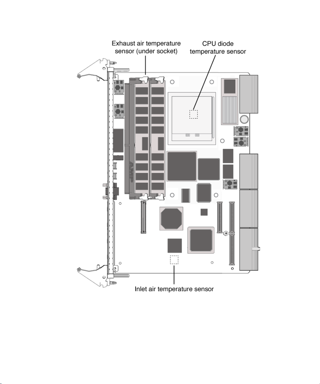
FIGURE 2-2 Location of Environmental Monitoring Hardware on the Netra CP2500 Board – Top Side
FIGURE 2-3 is a block diagram of the environmental monitoring functions.
Chapter 2 Environmental Monitoring 29
Page 44

die temperature
CPU
sensor
CPU
Southbridge
SMC micro
controller
I2C controller
Solaris
SMC
driver
OpenBoot PROM
PLD
PICL
application
program
I2C MUX
external I
Exhaust
temperature
sensor
ADM 1026
system
monitor
Inlet temperature
sensor
FIGURE 2-3 Netra CP2500 Board Environmental Monitoring Functional Block Diagram
30 Netra CP2500 Board Programming Guide • March 2007
cPCI J5
Power
control
and monitor
2
C
Page 45

Switching Power On and Off
The on-board voltage controller allows power to the CPU of the Netra CP2500 only
when the following conditions are met:
■ The VDD core-1.1-volt supply voltage is greater than 1.0 volts (within 10% of
nominal).
■ The 12-volt supply voltage is greater than 10.8 volts (within 10% of nominal).
■ The 5-volt supply voltage is greater than 4.5 volts (within 10% of nominal)
■ The 3.3-volt supply voltage is greater than 3.0 volts (within 10% of nominal).
The controller requires these conditions to be true for at least 100 milliseconds to
help ensure the supply voltages are stable. If any of these conditions become untrue,
the voltage monitoring circuit shuts down the CPU power of the board.
Inlet, Exhaust, and CPU Temperature Monitoring
The CPU diode sensor reading may vary from slot to slot and from board to board in
a system, and is dependent primarily on system cooling. As an example, a system
might have sensor readings for the CPU diode from 35˚C to 49˚C with an ambient
inlet of 21˚C across many boards, with a variety of configurations and positions
within a chassis. Care must be taken when setting the alarm and shutdown
temperatures based on the CPU diode sensor value. This sensor typically is linear
across the operating range of the board.
The exhaust sensor measures the local air temperature at the trailing edge of the
board for systems with bottom to top airflow. This value depends on the character
and volume of the airflow across the board. Typical values in a chassis may range
from a delta over inlet ambient of 0˚C to 12˚C, depending on the power dissipation
of the board configuration and the position in the chassis. The exhaust sensor is
nonlinear with respect to ambient inlet temperature.
The inlet sensor measures the local air temperature at the leading edge of the board
on the solder side under the solder-side cover. This value typically can range from a
reading of 0˚C to 13˚C above inlet system ambient in a chassis. Care must be taken to
understand the application and installation of the board to use this temperature
sensor.
A sudden drop of all temperature sensors close to or near room ambient temperature
can mean loss of power to one or more Netra CP2500s.
A gradual increase in the delta temperature from inlet to outlet can be due to dust
clogging system filters. This feature can be used to set service levels for filter
cleaning or changing.
Chapter 2 Environmental Monitoring 31
Page 46

The CPU diode temperature can be used to prevent damage to the board by shutting
the board down if this sensor exceeds predetermined limits.
Adjusting the Environmental Monitoring Warning, Critical, and Shutdown Parameter Settings on the Board
The Netra CP2500 uses the environmental monitoring detection system to monitor
the temperature of the board. The environmental monitoring system will display
messages if the board temperature exceeds the warning and critical settings. Because
the on-board sensors may report different temperature readings for different system
configurations and airflows, you might want to adjust the warning, critical, and
shutdown temperature parameter settings.
The Netra CP2500 determines the board temperature by retrieving temperature data
from sensors located on the board. A board sensor reads the temperature of the
immediate area around the sensor. Although the software might appear to report the
temperature of a specific hardware component, the software is actually reporting the
temperature of the area near the sensor. For example, the CPU diode sensor reads
the temperature at the location of the sensor and not on the actual CPU heat sink.
The board’s OpenBoot PROM collects the temperature readings from each board
sensor at regular intervals. You can display these temperature readings using the
show-sensors OpenBoot PROM command. See “Using the show-sensors
Command at the OpenBoot PROM” on page 34.
The temperature read by the CPU sensor will trigger OpenBoot PROM warning and
critical messages. When the CPU sensor reads a temperature greater than the
warning parameter setting, the OpenBoot PROM will display a warning message.
When the sensor reads a temperature greater than the shutdown setting, the SMC
will shut down the board.
Many factors affect the temperature readings of the sensors, including the airflow
through the system, the ambient temperature of the room, and the system
configuration. These factors might contribute to the sensors reporting different
temperature readings than expected.
The Netra CP2500 board CPU sensor default temperature threshold values are 110˚C
for the high warning temperature, 118˚C for the high shutdown temperature, and
123˚C for the high power-off temperature.
32 Netra CP2500 Board Programming Guide • March 2007
Page 47

Note – If you have developed an application that uses the environmental
monitoring software to monitor the temperature sensors, you may want to adjust
your application’s settings accordingly.
OpenBoot PROM Environmental Monitoring
This section describes the OpenBoot PROM environmental monitoring of the CPU.
Warning Temperature Response at OpenBoot PROM
When the CPU diode temperature reaches warning temperature, a similar message
is displayed at the ok prompt at a regular interval:
Temperature sensor #2 has threshold event of
<<< WARNING!!! Upper Non-critical - going high >>>
The current threshold setting is : 110
The current temperature is : 111
Critical Temperature Response at OpenBoot PROM
When the CPU diode temperature reaches critical temperature, a similar message is
displayed at the
Temperature sensor #2 has threshold event of
<<< ALERT!!! Upper Critical - going high >>>
The current threshold setting is : 118
The current temperature is : 119
ok prompt at a regular interval:
Chapter 2 Environmental Monitoring 33
Page 48

Using the show-sensors Command at the OpenBoot PROM
The show-sensors command at OpenBoot PROM displays the readings of all the
temperature sensors on the board. A sample output for typical sensor readings for a
Netra CP2500 is as follows:
ok show-sensors
Sensor# Sensor Name Sensor Reading
======= ==================================== ===================
1 EP 5v Sensor (d1) 4.968 volts
2 EP 3.3v Sensor (8b) 3.336 volts
3 BP +12v Sensor (ce) 11.760 volts
4 BP -12v Sensor (63) -12.010 volts
5 IPMB Power Sensor (d2) 4.968 volts
6 SMC Power Sensor (69) 2.448 volts
7 VDD 3.3v Sensor (a8) 3.2592 volts
8 VCCP Sensor (64) 1.1800 volts
9 +12v Sensor (ba) 11.6250 volts
a -12v Sensor (36) -12.040 volts
b +5v Sensor (be) 4.940 volts
c Standby 3.3v Sensor (be) 3.2680 volts
d Main 3.3v Sensor (be) 3.2680 volts
e External I temp (CPU) Sensor (3e) 62 degree C
f External II temp (Outlet) Sensor (20) 32 degree C
10 Internal temp (Inlet) Sensor (1d) 29 degree C
ok
Environmental Monitoring Application Programming
The following sections describe how to use the environmental monitoring functions
in an application program.
For the environmental monitoring application program (envmond) to monitor the
hardware environment, the following conditions must be met:
■ The system controller device driver must be installed.
■ The environmental monitoring application program (envmond) must be installed
and running.
34 Netra CP2500 Board Programming Guide • March 2007
Page 49

The environmental monitoring parameter values in the application program apply
when the system is running at the Solaris level and do not necessarily have to be the
same as the default settings programmed by the SMC and used by the OpenBoot
PROM. The OpenBoot PROM environmental monitoring only applies when the
system is running at the OpenBoot PROM level.
Reading Temperature Sensor States Using the PICL API
Temperature sensor states may be read using the libpicl API. The following
properties are supported in a PICL temperature sensor class node:
TABLE 2-4 PICL Temperature Sensor Class Node Properties
Property Type Description
LowWarningThreshold INT Low threshold for warning
LowShutdownThreshold INT Low threshold for shutdown
LowPowerOffThreshold INT Low threshold for power off
HighWarningThreshold INT High threshold for warning
HighShutdownThreshold INT High threshold for shutdown
HighPowerOffThreshold INT High threshold for power off
The PICL plug-in receives these sensor events and updates the State property based
on the information extracted from the IPMI message. It then posts a PICL event.
Threshold levels of the PICL node class temperature sensor are:
■ Warning
■ Shutdown
■ Power Off
To obtain a reading of temperature sensor states, use the prtpicl -v command:
# prtpicl -c temperature-sensor -v
Sample PICL output of temperature sensors on a Netra CT system is as follows.
# prtpicl -c temperature-sensor -v
CPU-sensor (temperature-sensor, 2600000041f)
:Condition ok
:HighPowerOffThreshold 123
Chapter 2 Environmental Monitoring 35
Page 50

:HighShutdownThreshold 118
:HighWarningThreshold 110
:LowPowerOffThreshold -20
:LowShutdownThreshold -10
:LowWarningThreshold -5
:Temperature 74
:Label Ambient
:GeoAddr 0xe
:_class temperature-sensor
:name CPU-sensor
Using a Configuration File for Sensor Information
On the Netra CP2500, you can enable or disable sensors, and configure sensor
threshold actions, such as shutdown and reboot, by editing the
/etc/picl/config/envmond.conf file.
Sample entries in the envmond.conf file are:
#entry format: name=value option
envmon-enable = true /* Globally enables/disables PICL-based
environmental monitoring */
sensor=CP2500-CPU-sensor threshold_shutdown_cmd=“usr/sbin/shutdown -i5 -y -g15&”
/* presence of this line shows that the corresponding sensor is enabled */
Solaris Driver Interface
The PICL envmond plug-in opens a SMC driver stream and requests sensor events.
The SMC monitors the sensors and generates an event when it detects a change at a
particular sensor which meets one of the specified thresholds and generates an event
to local Solaris software. This event is captured by the SMC driver (as an IPMI
message) and is sent on an open STREAM that has requested sensor events. The
sensor events are received by the PICL plug-in. The PICL plug-in updates the State
property based on the information it extracts from the IPMI message and posts a
PICL event.
36 Netra CP2500 Board Programming Guide • March 2007
Page 51

Sample Application Program
This section presents a sample environmental monitoring (envmond) application
that monitors the CPU diode temperature.
CODE EXAMPLE 2-1 Sample envmond Application Program
/*
* sensor_readwrite.c
*
* compile: cc sensor_readwrite.c -lthread -lpicl -o sensor_readwrite
*/
#include <stdio.h>
#include <picl.h>
#define HI_POWEROFF_THRESHOLD "HighPowerOffThreshold"
#define HI_SHUTDOWN_THRESHOLD "HighShutdownThreshold"
#define HI_WARNING_THRESHOLD "HighWarningThreshold"
#define LO_POWEROFF_THRESHOLD "LowPowerOffThreshold"
#define LO_SHUTDOWN_THRESHOLD "LowShutdownThreshold"
#define LO_WARNING_THRESHOLD "LowWarningThreshold"
#define CURRENT_TEMPERATURE "Temperature"
static int
get_child_by_name(picl_nodehdl_t nodeh, char *name, picl_nodehdl_t *resulth)
{
picl_nodehdl_t childh;
picl_nodehdl_t nexth;
char propname[PICL_PROPNAMELEN_MAX];
picl_errno_t rc;
/* look up first child node */
rc = picl_get_propval_by_name(nodeh, PICL_PROP_CHILD, &childh,
sizeof (picl_nodehdl_t));
if (rc != PICL_SUCCESS) {
return (rc);
}
/* step through child nodes looking for named node */
while (rc == PICL_SUCCESS) {
rc = picl_get_propval_by_name(childh, PICL_PROP_NAME,
propname, sizeof (propname));
if (rc != PICL_SUCCESS) {
return (rc);
}
if (name && strcmp(propname, name) == 0) {
/* yes - got it */
Chapter 2 Environmental Monitoring 37
Page 52

CODE EXAMPLE 2-1 Sample envmond Application Program (Continued)
*resulth = childh;
return (PICL_SUCCESS);
}
if (get_child_by_name(childh, name, resulth) == PICL_SUCCESS) {
return (PICL_SUCCESS);
}
/* get next child node */
rc = picl_get_propval_by_name(childh, PICL_PROP_PEER,
&nexth, sizeof (picl_nodehdl_t));
if (rc != PICL_SUCCESS) {
return (rc);
}
childh = nexth;
}
return (rc);
}
void
get_sensor_thresholds(picl_nodehdl_t nodeh)
{
int8_t threshold;
if (picl_get_propval_by_name(nodeh, HI_POWEROFF_THRESHOLD,
&threshold, sizeof (threshold)) != PICL_SUCCESS) {
fprintf(stderr, "Failed to read high power-off threshold.");
} else
fprintf(stdout, "High power-off threshold = %d\n", threshold);
if (picl_get_propval_by_name(nodeh, HI_SHUTDOWN_THRESHOLD,
&threshold, sizeof (threshold)) != PICL_SUCCESS) {
fprintf(stderr, "Failed to read high shutdown threshold.");
} else
fprintf(stdout, "High shutdown threshold = %d\n", threshold);
if (picl_get_propval_by_name(nodeh, HI_WARNING_THRESHOLD,
&threshold, sizeof (threshold)) != PICL_SUCCESS) {
fprintf(stderr, "Failed to read high warning threshold.");
} else
fprintf(stdout, "High warning threshold = %d\n", threshold);
if (picl_get_propval_by_name(nodeh, LO_POWEROFF_THRESHOLD,
&threshold, sizeof (threshold)) != PICL_SUCCESS) {
fprintf(stderr, "Failed to read low power-off threshold.");
} else
fprintf(stdout, "Low shutdown threshold = %d\n", threshold);
38 Netra CP2500 Board Programming Guide • March 2007
Page 53

CODE EXAMPLE 2-1 Sample envmond Application Program (Continued)
if (picl_get_propval_by_name(nodeh, LO_SHUTDOWN_THRESHOLD,
&threshold, sizeof (threshold)) != PICL_SUCCESS) {
fprintf(stderr, "Failed to read low shutdown threshold.");
} else
fprintf(stdout, "Low shutdown threshold = %d\n", threshold);
if (picl_get_propval_by_name(nodeh, LO_WARNING_THRESHOLD,
&threshold, sizeof (threshold)) != PICL_SUCCESS) {
fprintf(stderr, "Failed to read low warning threshold.");
} else
fprintf(stderr, "Low warning threshold = %d\n", threshold);
}
void
set_sensor_thresholds(picl_nodehdl_t nodeh, char *threshold, int8_t value)
{
int8_t new_value = value;
if (picl_set_propval_by_name(nodeh, threshold, &new_value,
sizeof (new_value)) != PICL_SUCCESS)
fprintf(stderr, "Failed to set *s\n", threshold);
}
int
main(void)
{
int warning_temp;
int8_t temp;
char *sensor = "CPU-sensor";
picl_nodehdl_t rooth;
picl_nodehdl_t platformh;
picl_nodehdl_t childh;
if (picl_initialize() != PICL_SUCCESS) {
fprintf(stderr, "Failed to initialise picl\n");
return (1);
}
if (picl_get_root(&rooth) != PICL_SUCCESS) {
fprintf(stderr, "Failed to get root node\n");
picl_shutdown();
return (1);
}
if (get_child_by_name(rooth, "platform", &platformh) != PICL_SUCCESS) {
fprintf(stderr, "Failed to get platform node\n");
picl_shutdown();
Chapter 2 Environmental Monitoring 39
Page 54

CODE EXAMPLE 2-1 Sample envmond Application Program (Continued)
return (1);
}
if (get_child_by_name(platformh, sensor, &childh) != PICL_SUCCESS) {
fprintf(stderr, "Failed to get %s sensor.", sensor);
picl_shutdown();
return (1);
}
get_sensor_thresholds(childh);
/* Read current sensor temperature */
if (picl_get_propval_by_name(childh, CURRENT_TEMPERATURE,
&temp, sizeof (temp)) != PICL_SUCCESS) {
fprintf(stderr, "Failed to read current temperature\n");
} else
fprintf(stdout, "Current temperature = %d\n", temp);
set_sensor_threshold(childh, HI_WARNING_THRESHOLD, temp+5);
picl_shutdown();
return (0);
}
40 Netra CP2500 Board Programming Guide • March 2007
Page 55

Reading the CPU Temperature and Environmental Limits
You can access the CPU temperature sensor current readings and environmental
monitoring settings from the Solaris prompt by typing the following commands.
Sample output is listed after each command.
prtpicl command example:
# prtpicl -c temperature-sensor -v
CPU-sensor (temperature-sensor, 2600000041f)
:Condition ok
:HighPowerOffThreshold 123
:HighShutdownThreshold 118
:HighWarningThreshold 110
:LowPowerOffThreshold -20
:LowShutdownThreshold -10
:LowWarningThreshold -5
:Temperature 74
:Label Ambient
:GeoAddr 0xe
:_class temperature-sensor
:name CPU-sensor
prtdiag command example:
# prtdiag -v
...
CPU Node Temperature Information
--------------------------------
Temperature Reading: 85
Critical Threshold Information
-----------------------------High Power-Off Threshold 123
High Shutdown Threshold 118
High Warning Threshold 110
Low Power Off Threshold -20
Low Shutdown Threshold -10
Low Warning Threshold -5
Chapter 2 Environmental Monitoring 41
Page 56

TABLE 2-5 shows which Solaris commands correspond to the environmental
monitoring warning that runs when the CPU temperature exceeds the set limit.
TABLE 2-5 Description of Values Displayed by Solaris Commands
Environmental Monitoring Warning
The first-level temperature
warning is displayed.
The second-level temperature
warning is displayed.
The CPU is shut off.
prtpicl prtdiag
HighWarning
Threshold
HighShutdown
Threshold
HighPowerOff
Threshold
High Warning
Threshold
High Shutdown
Threshold
High Power-Off
Threshold
42 Netra CP2500 Board Programming Guide • March 2007
Page 57

CHAPTER
3
User Flash
This chapter describes the user flash driver for the onboard flash PROM and how to
use it. The Netra CP2500 is equipped with user flash memory. This chapter includes
the following sections:
■ “User Flash Usage and Implementation” on page 43
■ “User Flash Driver” on page 44
■ “Application Programming Interface” on page 45
■ “Example Programs” on page 47
User Flash Usage and Implementation
You can use the flash memory for various purposes, such as storage for RTOS, user
data storage, and OpenBoot PROM information. The Netra CP2500 has a 16Mbyte
flash that is logically divided into two parts: 2Mbytes for the system/boot flash and
14Mbytes for the user flash.
The main OpenBoot PROM image and a backup copy of the image are stored in the
system flash. If the OpenBoot PROM is corrupted, you can boot the OpenBoot
PROM from the backup copy to get a good OpenBoot PROM image back into the
system flash. On a Netra CP2500, the SW3301 dip switch on the board itself can be
changed to allow you to boot from the backup copy. Refer to the Netra CP2500
Installation and Technical Reference Manual for information on this dip switch.
43
Page 58

User Flash Driver
The uflash is the device driver for the flash PROM device on the Netra CP2500.
Access to the driver is carried out through open, read, write, pread, pwrite and
ioctl system interfaces.
On the Netra CP2500, one device is supported. There is one logical device file for the
physical device that can be accessed from applications. Users can use this device for
storing applications and data.
An instance of the driver is loaded for the device. The driver blocks any reads to the
device while a write is in progress. Multiple, concurrent reads can go through to the
same device at the same time. Writes to a device occur one at a time. All read and
write operations are supported at this time.
The device also supports erase and lock features. Applications can use them through
the IOCTL interface. The device is divided into logical blocks. Applications that
issue these operations also supply a block number or a range of blocks that are a
target of these operations. Locks are preserved across reboots. Locking a block
prevents an erase or write operation on that block.
OpenBoot PROM Device Tree and Properties
This section provides information on the user flash OpenBoot PROM device node
and its properties.
The user flash OpenBoot PROM device node is
/pci@1e,600000/isa@7/flashprom@2,0.
See
TABLE 3-1 for the user flash node properties.
TABLE 3-1 User Flash Node Properties
Property Description/Value
sunw,location U38
system-banks 00 00 00 00 00 00 00 01 00 00 00 02 00 00 00 03
flash-banks 00 00 00 00 00 00 00 1f
write-window 00 08 00 00 00 08 00 00
boot-banks 00 00 00 00 00 00 00 02 00 00 00 04 00 00 00 06
boot-window 00 00 00 00 00 08 00 00
44 Netra CP2500 Board Programming Guide • March 2007
Page 59

TABLE 3-1 User Flash Node Properties (Continued) (Continued)
Property Description/Value
bank-size 00080000
model SUNW,370-xxxx
version version number
name flashprom
compatible isa-flashprom
reg 00000002 00000000 00100000
User Flash Device Files
The user flash device file is /dev/uflash0.
Interface (Header) File
The user flash header file is located in the following path:
/usr/platform/SUNW,Netra-CP2500/include/sys/uflash_if.h
Application Programming Interface
Access to the user flash device from the Solaris OS is through an application or user
C program. No command-line tool is available. User programs open this device file
and then issue read, write, or ioctl commands to use the user flash device.
The system calls are listed below in
TABLE 3-2 System Calls
Call Description
read(), pread() Reads device
pwrite() Writes device
ioctl() Erases device, queries device parameters
TABLE 3-2.
Chapter 3 User Flash 45
Page 60

The ioctl supported commands are listed below:
#define UIOCIBLK (uflashIOC|0) /* identify */
#define UIOCQBLK (uflashIOC|1) /* query a block */
#define UIOCLBLK (uflashIOC|2) /* lock a block */
#define UIOCCLCK (uflashIOC|4) /* clear all locks */
#define UIOCEBLK (uflashIOC|5) /* erase a block */
Note that these ioctl commands are not supported:
#define UIOCMLCK (uflashIOC|3) /* master lock */
#define UIOCEALL (uflashIOC|6) /* erase all unlocked blocks */
#define UIOCEFUL (uflashIOC|7) /* erase full chip */
Structures to Use in IOCTL Arguments
PROM Information Structure
The PROM information structure holds device information returned by the driver in
response to an identify command.
CODE EXAMPLE 3-1 PROM Information Structure
/*
* PROM info structure.
*/
typedef struct {
uint16_t mfr_id; /* manufacturer id */
uint16_t dev_id; /* device id */
/* allow future expansion */
int8_t blk_status[256]; /* blks status filled
by driver */
int32_t blk_num; /* total # of blocks */
int32_t blk_size; /* # of bytes per block */
} uflash_info_t;
46 Netra CP2500 Board Programming Guide • March 2007
Page 61

User Flash User Interface Structure
The user flash user interface structure holds user parameters to commands such as
erase.
CODE EXAMPLE 3-2 User Flash Interface Structure
/*
* uflash user interface structure.
*/
typedef struct {
int blk_num;
int num_of_blks;
uflash_info_t info; /* to be filled by the
driver */
} uflash_if_t;
Errors
EINVAL Application passed one or more incorrect arguments to the system
call.
EACCESS Write or Erase operation was attempted on a locked block.
ECANCELLED A hardware malfunction has been detected. Normally, retrying the
command should fix this problem. If the problem persists, power
cycling the system might be necessary.
ENXIO This error indicates problems with the driver state. Power cycle of
the system or reinstallation of driver may be necessary.
EFAULT An error was encountered when copying arguments between the
application and driver (kernel) space.
ENOMEM System was low on memory when the driver attempted to acquire it.
EBUSY A write operation is already in progress when more than one
write requests are made.
Example Programs
Example programs are provided in this section for the following actions on user
flash device:
■ Read
Chapter 3 User Flash 47
Page 62

■ Write
■ Block Erase
Read Example Program
CODE EXAMPLE 3-3 contains the Read Action on the user flash device.
CODE EXAMPLE 3-3 Read Action on User Flash Device
/*
* uflash_read.c
* An example that shows how to read user flash
*/
#include <sys/types.h>
#include <sys/stat.h>
#include <fcntl.h>
#include <stdio.h>
#include <stdlib.h>
#include <string.h>
#include <errno.h>
#include <uflash_if.h>
char *uflash0 = "/dev/uflash0";
int ufd0;
uflash_if_t ufif0;
char *buf0;
char *module;
static int
uflash_init() {
char *buf0 = malloc(ufif0.info.blk_size);
if (!buf0) {
printf("%s: cannot allocate memory\n", module);
return(-1);
}
/* open device */
if ((ufd0 = open(uflash0, O_RDWR)) == -1 ) {
perror("uflash0: ");
exit(1);
}
/* get uflash sizes */
if (ioctl(ufd0, UIOCIBLK, &ufif0) == -1 ) {
perror("ioctl(ufd0, UIOCIBLK): ");
exit(1);
}
if (ufd0) {
printf("%s: \n", uflash0);
printf("manfacturer id = 0x%p\n", ufif0.info.mfr_id);
printf("device id = 0x%p\n", ufif0.info.dev_id);
48 Netra CP2500 Board Programming Guide • March 2007
Page 63

CODE EXAMPLE 3-3 Read Action on User Flash Device (Continued)
printf("number of blocks = 0x%p", ufif0.info.blk_num);
printf("block size = 0x%p" ufif0.info.blk_size);
}
static int
uflash_uninit() {
if (ufd0)
close(ufd0);
cleanup:
if (buf0)
free(buf0);
}
static int
uflash_read() {
/* read block 0 of user flash */
if (pread(ufd0, buf0, ufif0.info.blk_size, 0) != ufif0.info.blk_size)
perror("uflash0:read");
return(0);
}
main() {
int ret;
module = argv[0];
ret = uflash_init();
if (!ret)
uflash_read();
uflash_uninit();
}
Write Example Program
CODE EXAMPLE 3-4 contains the Write Action on the user flash device.
CODE EXAMPLE 3-4 Write Action on User Flash Device
/*
* uflash_write.c
* An example that shows how to write user flash
*/
#include <sys/types.h>
#include <sys/stat.h>
#include <fcntl.h>
#include <stdio.h>
#include <stdlib.h>
#include <string.h>
#include <errno.h>
#include <uflash_if.h>
char *uflash0 = "/dev/uflash0";
Chapter 3 User Flash 49
Page 64

CODE EXAMPLE 3-4 Write Action on User Flash Device (Continued)
int ufd0;
uflash_if_t ufif0;
char *buf0;
char *module;
static int
uflash_init() {
char *buf0 = malloc(ufif0.info.blk_size);
if (!buf0) {
printf("%s: cannot allocate memory\n", module);
return(-1);
}
/* open device */
if ((ufd0 = open(uflash0, O_RDWR)) == -1 ) {
perror("uflash0: ");
exit(1);
}
/* get uflash sizes */
if (ioctl(ufd0, UIOCIBLK, &ufif0) == -1 ) {
perror("ioctl(ufd0, UIOCIBLK): ");
exit(1);
}
if (ufd0) {
printf("%s: \n", uflash0);
printf("manfacturer id = 0x%p\n", ufif0.info.mfr_id);
printf("device id = 0x%p\n", ufif0.info.dev_id);
printf("number of blocks = 0x%p", ufif0.info.blk_num);
printf("block size = 0x%p" ufif0.info.blk_size);
}
}
static int
uflash_uninit() {
if (ufd0)
close(ufd0);
cleanup:
if (buf0)
free(buf0);
}
static int
uflash_write() {
int i;
/* write some pattern to the buffers */
for (i = 0; i < ufif0.info.blk_size; i += sizeof(int))
*((int *) (buf0 + i)) = 0xDEADBEEF;
/* write block 0 of user flash */
if (pwrite(ufd0, buf0, ufif0.info.blk_size, 0) != ufif0.info.blk_size)
perror("uflash0:write");
return(0);
50 Netra CP2500 Board Programming Guide • March 2007
Page 65

CODE EXAMPLE 3-4 Write Action on User Flash Device (Continued)
}
main() {
int ret;
module = argv[0];
ret = uflash_init();
if (!ret)
uflash_write();
uflash_uninit();
}
Block Erase Example Program
CODE EXAMPLE 3-5 contains the Block Erase Action on the user flash device.
CODE EXAMPLE 3-5 Block Erase Action on User Flash Device
/*
* uflash_blockerase.c
* An example that shows how to erase block(s) of user flash
*/
#include <sys/types.h>
#include <sys/stat.h>
#include <fcntl.h>
#include <stdio.h>
#include <stdlib.h>
#include <string.h>
#include <errno.h>
#include <uflash_if.h>
char *uflash0 = "/dev/uflash0";
int ufd0;
uflash_if_t ufif0;
char *module;
static int
uflash_init() {
/* open device */
if ((ufd0 = open(uflash0, O_RDWR)) == -1 ) {
perror("uflash0: ");
exit(1);
}
/* get uflash sizes */
if (ioctl(ufd0, UIOCIBLK, &ufif0) == -1 ) {
perror("ioctl(ufd0, UIOCIBLK): ");
exit(1);
}
if (ufd0) {
printf("%s: \n", uflash0);
Chapter 3 User Flash 51
Page 66

CODE EXAMPLE 3-5 Block Erase Action on User Flash Device (Continued)
printf("manfacturer id = 0x%p\n", ufif0.info.mfr_id);
printf("device id = 0x%p\n", ufif0.info.dev_id);
printf("number of blocks = 0x%p", ufif0.info.blk_num);
printf("block size = 0x%p" ufif0.info.blk_size);
}
}
static int
uflash_uninit() {
if (ufd0)
close(ufd0);
}
static int
uflash_blockerase() {
/* erase 2 blocks starting from block 1 of user flash */
uf0.blk_num = 1;
uf0.num_of_blks = 2;
if (ufd0 && ioctl(ufd0, UIOCEBLK, &ufif0) == -1 ) {
perror("ioctl(ufd0, UIOCEBLK): ");
return(-1);
}
printf("\nblockerase successful on %s\n", uflash0);
return(0);
}
main() {
int ret;
module = argv[0];
ret = uflash_init();
if (!ret)
uflash_blockerase();
uflash_uninit();
}
52 Netra CP2500 Board Programming Guide • March 2007
Page 67

Sample User Flash Application Program
You can use the following program to test the user flash device and driver. This
program also demonstrates how this device can be used.
CODE EXAMPLE 3-6 Sample User Flash Application Program
/*
*
* This application program demonstrates the user program
* interface to the User Flash PROM driver.
*
* One can read or write a number of bytes up to the size of
* the user PROM by means of pread() and pwrite() calls.
* All other functions of the PROM can be accessed by
* means of ioctl() calls such as:
* -) identify the chip,
* -) query block,
* -) lock block/unlock block,
* -) erase block
* Please note that not all of the above ioctl calls are
* available for all flash PROMs. It is the user’s
* responsibility to find out the features of a given PROM.
* The type, block size, and number of blocks of the PROM
* are returned by "identify" ioctl().
*
* The pwrite() erases the block[s] and then does the
* writing.
*
* Use the following line to compile your custom application
* programs:
* make uflash_test
*/
#pragma ident "@(#)uflash_test.c 1.0 03/04/30 SMI"
#include <stdio.h>
#include <sys/signal.h>
#include <stdio.h>
#include <sys/time.h>
#include <errno.h>
#include <sys/types.h>
#include <sys/fcntl.h>
#include <sys/stream.h>
#include "uflash_if.h"
/*
*/
Chapter 3 User Flash 53
Page 68

CODE EXAMPLE 3-6 Sample User Flash Application Program (Continued)
#if 1
#define PROM_SIZE 0x700000 /* 7 MBytes */
#endif
static char *help[14] = {
"0 -- read user flash PROM",
"1 -- write user flash PROM",
"2 -- identify user flash PROM",
"3 -- query blocks",
"4 -- lock blocks",
"5 -- clear all locks",
"6 -- erase blocks",
"q -- quit",
"?/h -- display this menu",
""
};
/*char get_cmd(); */
static char
get_cmd()
{
char buf[10];
gets(buf);
return (buf[0]);
}
/*
* Main
*/
main(int argc, char *argv[])
{
int n_byte; /* returned from pread/pwrite */
int size, offset, pat;
int fd0, h, i;
int fd, prom_id;
uflash_if_t uflash_if;
caddr_t r_buf, w_buf;
char *devname0 = "/dev/uflash0";
char c;
r_buf = (caddr_t)malloc(PROM_SIZE);
w_buf = (caddr_t)malloc(PROM_SIZE);
/*
* Open the user flash PROM.
*/
54 Netra CP2500 Board Programming Guide • March 2007
Page 69

CODE EXAMPLE 3-6 Sample User Flash Application Program (Continued)
if ((fd0 = open(devname0, O_RDWR)) < 0) {
fprintf(stderr, "couldn’t open device: %s\n", devname0);
exit(1);
}
/* set the default PROM */
prom_id = 0;
fd = fd0;
/* let them know about the help menu */
fprintf(stderr, "Enter <h> or <?> for help on commands\n");
while (1) {
fprintf(stderr, "[%d]command> ", prom_id);
switch(get_cmd()) {
case ’q’:
goto getout;
case ’h’:
case ’?’:
h = 0;
while (*help[h]){
fprintf(stderr, " %s\n", help[h]);
h++;
}
break;
case ’6’: /* erase flash PROM block */
fprintf(stderr,
"Enter PROM block number[0, 56]> ");
scanf ("%d", &uflash_if.blk_num);
fprintf(stderr,
"Enter number of block> ");
scanf ("%d", &uflash_if.num_of_blks);
if (ioctl(fd, UIOCEBLK, &uflash_if) == -1)
goto getout;
break;
case ’5’: /* clear all locks */
if (ioctl(fd, UIOCCLCK, &uflash_if) == -1)
goto getout;
break;
Chapter 3 User Flash 55
Page 70

CODE EXAMPLE 3-6 Sample User Flash Application Program (Continued)
case ’4’: /* lock flash PROM block */
/* on certain PROMs */
fprintf(stderr,
"Enter PROM block number[0, 56]> ");
scanf ("%d", &uflash_if.blk_num);
fprintf(stderr,
"Enter number of block> ");
scanf ("%d", &uflash_if.num_of_blks);
if (ioctl(fd, UIOCLBLK, &uflash_if) == -1)
goto getout;
break;
case ’3’: /* query flash PROM */
/* on certain PROMs */
fprintf(stderr,
"Enter PROM block number[0, 56]> ");
scanf ("%d", &uflash_if.blk_num);
fprintf(stderr,
"Enter number of block> ");
scanf ("%d", &uflash_if.num_of_blks);
if (ioctl(fd, UIOCQBLK, &uflash_if) == -1)
goto getout;
for (i = uflash_if.blk_num;
i < (uflash_if.blk_num+uflash_if.num_of_blks);
i++)
{
fprintf(stderr, "block[%d] status = %x\n",
i, uflash_if.info.blk_status[i] & 0x1);
}
break;
case ’2’: /* identify flash PROM */
if (ioctl(fd, UIOCIBLK, &uflash_if) == -1)
goto getout;
fprintf(stderr, "manufacturer id = 0x%x, device id =\
0x%x\n# of blks = %d, blk size = 0x%x\n",
uflash_if.info.mfr_id & 0xFF,
uflash_if.info.dev_id & 0xFF,
uflash_if.info.blk_num,
uflash_if.info.blk_size);
break;
56 Netra CP2500 Board Programming Guide • March 2007
Page 71

CODE EXAMPLE 3-6 Sample User Flash Application Program (Continued)
case ’1’: /* write to user flash PROM */
fprintf(stderr,
"Enter PROM offset[0, 0xXX,XXXX]> ");
scanf ("%x", &offset);
fprintf(stderr,
"Enter number of bytes[hex]> ");
scanf ("%x", &size);
fprintf(stderr,
"Enter data pattern[0, 0xFF]> ");
scanf ("%x", &pat);
/*
* init write buffer.
*/
for (i = 0; i < size; i++) {
w_buf[i] = pat;
}
n_byte = pwrite (fd, w_buf, size, offset);
if (n_byte != size) {
/* the write failed */
printf ("Write process was failed at byte 0x%x \n",
n_byte);
}
break;
case ’0’: /* read from user flash PROM */
fprintf(stderr,
"Enter PROM offset[0, 0xXX,XXXX]> ");
scanf ("%x", &offset);
fprintf(stderr,
"Enter number of bytes[hex]> ");
scanf ("%x", &size);
getchar(); /* clean up the char buf */
n_byte = pread (fd, r_buf, size, offset);
if (n_byte != size) {
/* the read failed */
printf ("Read process was failed at \
byte 0x%x \n",
n_byte);
continue;
Chapter 3 User Flash 57
Page 72

CODE EXAMPLE 3-6 Sample User Flash Application Program (Continued)
}
printf ("\nuser data buffer:\n");
for (i = 0; i < size; i++) {
printf("%2x ", r_buf[i] & 0xff);
}
printf("\n");
default:
continue;
}
}
/* exit */
getout:
close(fd0);
return;
} /* end of main() */
58 Netra CP2500 Board Programming Guide • March 2007
Page 73

Index
B
boot, Solaris OS, 21
C
commands
prtdiag, 41, 42
prtpicl, 4, 35, 41, 42
show-sensors,34
critical-temperature parameter, 33
D
device node, 44
dip switch, 43
documentation, related, xiii
E
environmental monitoring, 23 to 42
application block diagram, 24
application program, 34
functional block diagram, 30
temperature monitoring, 32 to 33
envmond application program, 27, 34, 37 to 40
envmond.conf file, 36
I
Intelligent Platform Management Interface (IPMI)
commands, 27
IOCTL and user flash, 45 to 53
M
memory, 47
O
OpenBoot PROM
and environmental monitoring, 26
and user flash, 43, 44
and watchdog timer, 21
backup copy, 43
P
PICL
man pages, 2
temperature sensors, 35
watchdog plug-in, 2
PROM information structure, 46
prtdiag command, 41, 42
prtpicl command, 4, 35, 41, 42
R
RTOS, 43
S
show-sensors command, 34
SMC, 23
T
temperature, 26, 28, 31 to 34
timer, watchdog, 1 to 21
U
user data storage, 43
user flash
application program, 53
59
Page 74

device, 45
device files, 45
driver, 43
header file, 45
interface structure, 47
node properties, 44
V
voltage, 27, 31
voltage controller, 27, 31
W
warning-temperature parameter, 33
watchdog plug-ins, 3
watchdog timer, 1 to 21
watchdog-controller, 3, 4
watchdog-timer, 3, 4
60 Netra CP2500 Board Programming Guide • March 2007
 Loading...