


Sun Fire V250 Server
Parts Replacement Manual
Sun Microsystems, Inc.
4150 Network Circle
Santa Clara, CA 95054 U.S.A.
650-960-1300
Part No. 817-0901-10
September 2003, Revision A
Send comments about this document to: docfeedback@sun.com

Copyright 2003Sun Microsystems,Inc., 4150Network Circle,Santa Clara, California 95054, U.S.A. All rights reserved.
Sun Microsystems, Inc. has intellectual property rights relating to technology embodiedin the product that is described in this document. In
particular,and without limitation, these intellectual propertyrights may include one or more of the U.S. patents listed at
http://www.sun.com/patentsand one or more additional patents or pending patent applications in the U.S. and in other countries.
This document and the product to which it pertains are distributed under licenses restricting their use, copying, distribution, and
decompilation. No part of the product or of this document may be reproduced in any form by any means without prior written authorization of
Sun and its licensors, if any.
Third-partysoftware,includingfont technology,is copyrighted and licensed from Sun suppliers.
Parts of the product may be derived from Berkeley BSD systems, licensed from the University of California. UNIX is a registered trademark in
the U.S. and in other countries, exclusively licensed through X/Open Company, Ltd.
Sun, Sun Microsystems, the Sun logo, AnswerBook2, docs.sun.com, and Solaris are trademarks or registered trademarks of Sun Microsystems,
Inc. in the U.S. and in other countries.
All SPARCtrademarks are used under license and aretrademarks or registeredtrademarks of SPARCInternational, Inc. in the U.S. and in other
countries. Products bearing SPARCtrademarks are based upon an architecturedeveloped by Sun Microsystems, Inc.
The OPEN LOOK and Sun™ Graphical User Interface was developed by Sun Microsystems, Inc. for its users and licensees. Sun acknowledges
the pioneering efforts of Xerox in researching and developing the concept of visual or graphical user interfaces for the computer industry. Sun
holds a non-exclusive license from Xerox to the Xerox Graphical User Interface, which license also covers Sun’s licensees who implement OPEN
LOOK GUIs and otherwise comply with Sun’s written license agreements.
U.S. Government Rights—Commercial use. Government users are subject to the Sun Microsystems, Inc. standard license agreement and
applicable provisions of the FARand its supplements.
DOCUMENTATION IS PROVIDED "AS IS" AND ALL EXPRESS OR IMPLIED CONDITIONS, REPRESENTATIONS AND WARRANTIES,
INCLUDING ANY IMPLIED WARRANTYOF MERCHANTABILITY, FITNESS FOR A PARTICULAR PURPOSE OR NON-INFRINGEMENT,
ARE DISCLAIMED, EXCEPT TO THE EXTENT THAT SUCH DISCLAIMERS ARE HELD TO BE LEGALLY INVALID.
Copyright 2003 Sun Microsystems, Inc., 4150 Network Circle, Santa Clara, California 95054, Etats-Unis. Tousdroits réservés.
Sun Microsystems, Inc. a les droits de propriété intellectuels relatants à la technologie incorporée dans le produit qui est décritdans ce
document.Enparticulier,et sans la limitation, ces droits de propriété intellectuels peuvent inclureunouplusdes brevetsaméricainsénumérésà
http://www.sun.com/patents et un ou les brevets plus supplémentaires ou les applications de brevet en attente dans les Etats-Unis et dans les
autrespays.
Ce produit ou document est protégé par un copyright et distribué avec des licences qui en restreignentl’utilisation, la copie, la distribution, et la
décompilation. Aucune partie de ce produit ou document ne peut être reproduitesous aucune forme, par quelque moyen que ce soit, sans
l’autorisation préalable et écrite de Sun et de ses bailleurs de licence, s’il y ena.
Le logiciel détenu par des tiers, et qui comprend la technologie relative aux polices de caractères,estprotégépar un copyright et licencié par des
fournisseurs de Sun.
Des parties de ce produit pourront être dérivées des systèmes BerkeleyBSD licenciés par l’Université de Californie. UNIX est une marque
déposée aux Etats-Unis et dans d’autres pays et licenciée exclusivement par X/Open Company,Ltd.
Sun, Sun Microsystems, le logo Sun, AnswerBook2, docs.sun.com, et Solaris sont des marques de fabrique ou des marques déposées de Sun
Microsystems,Inc. aux Etats-Unis et dans d’autres pays.
Toutes les marques SPARC sont utilisées sous licence et sont des marques de fabrique ou des marques déposées de SPARC International, Inc.
aux Etats-Unis et dans d’autres pays. Les produits protant les marquesSPARC sont basés sur une architecture développée par Sun
Microsystems,Inc.
L’interfaced’utilisation graphique OPEN LOOK et Sun™ a été développée par Sun Microsystems,Inc. pour ses utilisateurs et licenciés. Sun
reconnaîtles effortsde pionniers de Xerox pour la recherche et le développement du concept des interfaces d’utilisation visuelle ou graphique
pour l’industrie de l’informatique. Sun détient une license non exclusive de Xerox sur l’interface d’utilisation graphique Xerox, cette licence
couvrantégalementles licenciées de Sun qui mettent en place l’interface d ’utilisation graphique OPEN LOOK et qui en outre se conforment aux
licences écrites de Sun.
LA DOCUMENTATION EST FOURNIE "EN L’ÉTAT" ET TOUTES AUTRES CONDITIONS, DECLARATIONS ET GARANTIES EXPRESSES
OU TACITESSONT FORMELLEMENT EXCLUES, DANS LA MESURE AUTORISEE PARLA LOI APPLICABLE, Y COMPRIS NOTAMMENT
TOUTE GARANTIE IMPLICITE RELATIVE A LA QUALITE MARCHANDE, A L’APTITUDE A UNE UTILISATION PARTICULIEREOU A
L’ABSENCE DE CONTREFAÇON.
Please
Recycle

Contents
Contents iii
Figures vii
Preface ix
1. Parts Installation and Removal 1
Lifting the Server 2
Replaceable Components 2
Controlling Server Power 3
▼ To Turn Server Power On 4
▼ To Turn Server Power Off 4
Avoiding Electrostatic Discharge 5
▼ To Avoid Electrostatic Discharge While Working on the Front of the
▼ To Avoid Electrostatic Discharge While Working On Internal
Service Panel 7
▼ To Remove the Service Panel 8
Location of Components 9
User Replaceable Components 11
Hard Disk Drives 11
Server 5
Components 6
Contents iii

▼ To Remove a Hard Disk Drive 11
▼ To Insert a Hard Disk Drive 12
Power Supply Unit 13
▼ To Replace a PSU 14
Service Provider Replaceable Components 15
System Configuration Card Reader Module 16
▼ To Remove the System Configuration Card Reader Module 16
▼ To Replace the System Configuration Card Reader Module 17
Power Distribution Board 18
▼ To Remove the Power Distribution Board 19
▼ To Replace the Power Distribution Board 22
Memory 22
Memory Configuration Rules 23
▼ To Add Memory 23
▼ To Remove Memory 24
Rear Cooling Fans 25
▼ To Remove the Fan Module 26
▼ To Replace the Fan Module 27
CPU Fan and Heatsink Assembly 27
▼ To Remove a CPU Fan and Heatsink Assembly 28
▼ To Replace a CPU Fan and Heatsink Assembly 29
System Board Assembly 30
▼ To Remove The System Board 31
PCI Cards 33
▼ To Add a PCI Card 33
▼ To Remove a PCI Card 35
SCSI Backplane 36
▼ To Remove the SCSI Backplane 36
Contents iv

▼ To Replace the SCSI Backplane 38
Tape Drive (Optional) 38
▼ To Install a Tape Drive 38
▼ To Remove the Tape Drive 40
DVD-ROM Drive 42
▼ To Remove the DVD-ROM Drive 42
▼ To Replace the DVD-ROM Drive 43
Front Fan Modules 44
▼ To Remove a Front Fan Module 45
▼ To Replace a Front Fan Module 46
Battery 46
▼ To Replace the Battery 47
Index 49
Contents v

vi Sun Fire V250 Server Parts Replacement Manual • September 2003

Figures
FIGURE 1-1 Front Panel Electrostatic Grounding Point 6
FIGURE 1-2 Back Panel Electrostatic Grounding Point 7
FIGURE 1-3 Location of the Service Panel Retaining Screws 8
FIGURE 1-4 Removing the Service Panel 9
FIGURE 1-6 Removing a Hard Disk Drive 12
FIGURE 1-7 Inserting a Hard Disk Drive 13
FIGURE 1-8 Removing A Power Supply Unit 14
FIGURE 1-9 Replacing A Power Supply Unit 15
FIGURE 1-10 Removing the System Configuration Card Reader Module 17
FIGURE 1-11 Replacing the System Configuration Card Reader Module 18
FIGURE 1-12 Power Distribution Board Retaining Screws 20
FIGURE 1-13 Power Distribution Board Removal 21
FIGURE 1-14 Power Distribution Board Replacement 22
FIGURE 1-15 Inserting a DIMM 24
FIGURE 1-16 Removing a DIMM 25
FIGURE 1-17 Disconnecting the Fan Module Power Cables 26
FIGURE 1-18 Removing the Fan Module 27
FIGURE 1-19 CPU Fan Removal 29
FIGURE 1-20 Removing a Processor Fan and Heat Sink Assembly 30
FIGURE 1-21 Removing System Board Power and Data Cables 31
Figures vii

FIGURE 1-22 Location of System Board Retaining Screw 32
FIGURE 1-23 Removing the System Board from the Chassis 33
FIGURE 1-24 PCI Card Retaining Mechanism 34
FIGURE 1-25 Moving the Support for Long PCI Cards 35
FIGURE 1-26 Location of SCSI Backplane and Fixing Screws 37
FIGURE 1-27 Tape Drive Blanking Plate Removal 39
FIGURE 1-28 Installing a Tape Drive Module 40
FIGURE 1-29 Removing the Optional Tape Drive 41
FIGURE 1-30 Removing the DVD-ROM Drive 43
FIGURE 1-31 Replacing a DVD-ROM Drive 44
FIGURE 1-32 Front Fan Module Removal 45
FIGURE 1-33 Replacing a Front Fan Module 46
FIGURE 1-34 Removing the Battery 47
viii Sun Fire V250 Server Parts Replacement Manual • September 2003

Preface
The Sun Fire V250 Server Parts Replacement Manual provides detailed instructions for
removing and replacing components of the server. Some of the procedures can be
carried out by the user, others by the service provider only.
Before You Read This Book
Read the Sun Fire V250 Server Compliance and Safety Manual before following any of
the procedures described in this book.
Using UNIX Commands
This document does not contain information on basic UNIX®commands and
procedures such as shutting down the system, booting the system, and configuring
devices.
See one or more of the following for this information:
■ Solaris Handbook for Sun Peripherals
■ Other software documentation that you received with your system
ix

Typographic Conventions
Typeface Meaning Examples
AaBbCc123 The names of commands, files,
and directories; on-screen
computer output
AaBbCc123
AaBbCc123 Book titles, new words or terms,
What you type, when contrasted
with on-screen computer output
words to be emphasized.
Replace command-line variables
with real names or values.
Edit your.login file.
Use ls -a to list all files.
% You have mail.
% su
Password:
Read Chapter 6 in the User’s Guide.
These are called class options.
You must be superuser to do this.
To delete a file, type rm filename.
Shell Prompts
Shell Prompt
C shell machine-name%
C shell superuser machine-name#
Bourne shell and Korn shell $
Bourne shell and Korn shell superuser #
ALOM shell sc>
OpenBoot PROM shell ok
x Sun Fire V250 Server Parts Replacement Manual • September 2003

Related Documentation
Application Title Part Number
Latest information Sun Fire V250 Server Product Notes 817-1003-xx
Compliance and Safety Sun Fire V250 Server Compliance and
Safety Manual
Unpacking Sun Fire V250 Server Quick Start Guide 817-0898-xx
Installation Sun Fire V250 Server Installation Guide 817-0899-xx
Administration Sun Fire V250 Server Administration
Guide
Lights-Out Management Advanced Lights-Out Manager Online
Help
Read the Sun Fire V250 Server Compliance and Safety Guide before performing any of
the procedures documented in this manual.
817-1959-xx
817-0900-xx
817-3175-xx
Accessing Sun Documentation Online
You can view, print, or purchase a broad selection of Sun documentation, including
localized versions, at:
http://www.sun.com/documentation/
Sun Welcomes Your Comments
Sun is interested in improving its documentation and welcomes your comments and
suggestions. You can email your comments to Sun at:
docfeedback@sun.com
Please include the part number (817-0901-xx) of your document in the subject line of
your email.
Preface xi

xii Sun Fire V250 Server Parts Replacement Manual • September 2003

CHAPTER
1
Parts Installation and Removal
This chapter contains procedures for replacing the server’s internal hardware
components.
Caution – The procedures in this section are for the attention of service providers
only.
Caution – Read “Avoiding Electrostatic Discharge” on page 5, and wear a properly
grounded antistatic strap, before you carry out any of the procedures in this book.
The chapter contains the following sections:
■ “Lifting the Server” on page 2
■ “Replaceable Components” on page 2
■ “Controlling Server Power” on page 3
■ “Avoiding Electrostatic Discharge” on page 5
■ “Service Panel” on page 7
■ “Location of Components” on page 9
■ “User Replaceable Components” on page 11
■ “Service Provider Replaceable Components” on page 15
1

Lifting the Server
Close the door before you lift the server. The server should be lifted by two people,
using the top part of the bezel at the front and the PSU handles at the back as
gripping points.
Replaceable Components
This section lists components that can be replaced by users and service providers.
■ Components listed in TABLE 1-1 can be replaced by the user.
■ Components listed in TABLE 1-2 can be replaced by the service provider only.
TABLE 1-1 User Replaceable Components
Component Part Number
Front door/hinge assembly F370-5960
Power supply unit F300-1588
Hard disk drive, 36GB 10K RPM F540-5462
Hard disk drive, 73GB 10K RPM F540-5455
System configuration card F370-5155
TABLE 1-2 Service Provider Replaceable Components
Component Part Number
Motherboard, 0 MB, single 1.064GHz CPU F375-3146
Motherboard, 0 MB, dual 1.064GHz CPU F375-3147
Motherboard, 0 MB, single 1.28GHz CPU F375-3176
Motherboard, 0 MB, dual 1.28GHz CPU F375-3130
SCC reader module F370-5646
Front fan F370-5962
Cable kit F370-6114
SCSI backplane F370-5959
Power distribution board F370-5961
2 Sun Fire V250 Server Parts Replacement Manual • September 2003

TABLE 1-2 Service Provider Replaceable Components
Component Part Number
Rear fan module F370-6084
ALOM card F501-6346
CPU heatsink with fan F370-5686
256MB DDR1 DIMM (pair) F370-5565
512MB DDR1 DIMM (pair) F370-4939
1GB DDR1 DIMM (pair) F370-4940
DVD Drive F370-5690
DAT Drive F390-0028
Caution – Printed circuit boards and hard disk drives contain electronic
components that are extremely sensitive to static electricity. The quantities of static
electricity generated by your clothes or your work environment can destroy some
components. Do not touch any components or metal parts without taking full
antistatic precautions.
Caution – Before you carry out any of the procedures covered in this book, the
server must be powered down.
Controlling Server Power
The only way to turn server power off is to disconnect the server from its power
source by removing the power cable or cables. The On/Standby button toggles the
server between the On and Standby power states only; it cannot turn server power
off.
For detailed information on controlling server’s power state using the software, refer
to the ALOM Online Documentation.
Chapter 1 Parts Installation and Removal 3

▼ To Turn Server Power On
Caution – Never move the server while it is powered on. Movement can cause disk
drive failure. Always power off the system before moving it.
1. Connect the server to an AC power source.
When the server is connected to a power source, it immediately enters Standby
power mode.
2. Turn on the power to any peripherals or external storage devices that are
connected to the server.
If you have connected an external device to the server, read the documentation that
was supplied with it for specific instructions.
3. Open the door.
4. Set the operation mode switch to the Normal or Diagnostics position.
5. Press the On/Standby button once.
6. Set the operation mode switch to the Locked position.
This prevents the server from being powered off accidentally.
7. Close and lock the door.
▼ To Turn Server Power Off
1. Notify users that the system will be powered down.
2. Back up system files and data.
3. Set the operation mode switch to the Normal or Diagnostics position.
4. Press and immediately release the On/Standby button.
This action initiates an orderly software system shutdown.
Note – Pressing and releasing the On/Standby switch initiates an orderly software
shutdown. Pressing and holding the switch for four seconds causes an immediate
hardware shutdown. Whenever possible, initiate an orderly shutdown. Forcing an
immediate hardware shutdown can corrupt the disk drive and cause loss of data.
5. Wait for the front panel green LED to go out.
4 Sun Fire V250 Server Parts Replacement Manual • September 2003

6. Disconnect the power cable.
This is the only way to remove power from the server. Electrical power is present
when the server is in Standby mode.
Caution – As long as the power cord is connected, electrical energy is present
inside the server.
Avoiding Electrostatic Discharge
Whenever you carry out service procedures on the server, follow these instructions
to prevent static electricity damaging the server’s internal components.
You need an antistatic wrist strap, an antistatic mat, or other suitable antistatic
surface.
When the AC power cord(s) are removed for a service action to be carried out,
provide a ground path to bring the following to the same electrical potential:
■ ESD protective components
■ Server
■ Antistatic mat
■ Service personnel
Electrostatic protection can be maintained at a potential above a zero voltage ground
reference as long as all items listed above are at the same potential.
▼ To Avoid Electrostatic Discharge While Working
on the Front of the Server
1. Turn system power off.
See “Controlling Server Power” on page 3.
Chapter 1 Parts Installation and Removal 5

2. Attach one end of the antistatic strap to the grounding point on the server’s front
panel behind the door, and the other to your wrist.
See
FIGURE 1-1.
FIGURE 1-1 Front Panel Electrostatic Grounding Point
▼ To Avoid Electrostatic Discharge While Working
On Internal Components
1. Turn server power off.
See “Controlling Server Power” on page 3.
6 Sun Fire V250 Server Parts Replacement Manual • September 2003

2. Attach one end of the antistatic strap to the grounding stud located on the server’s
back panel, and the other end to your wrist.
FIGURE 1-2 Back Panel Electrostatic Grounding Point
Service Panel
Remove the service panel, which is located on one side of the server, to gain access
to the internal components. The service panel is secured to the chassis by two screws
on the back edge of the server.
Caution – The procedures in this section are for the attention of service providers
only.
Chapter 1 Parts Installation and Removal 7
▼ To Remove the Service Panel
1. Turn server power off.
See “Controlling Server Power” on page 3.
2. Ensure you are properly grounded.
See “Avoiding Electrostatic Discharge” on page 5.
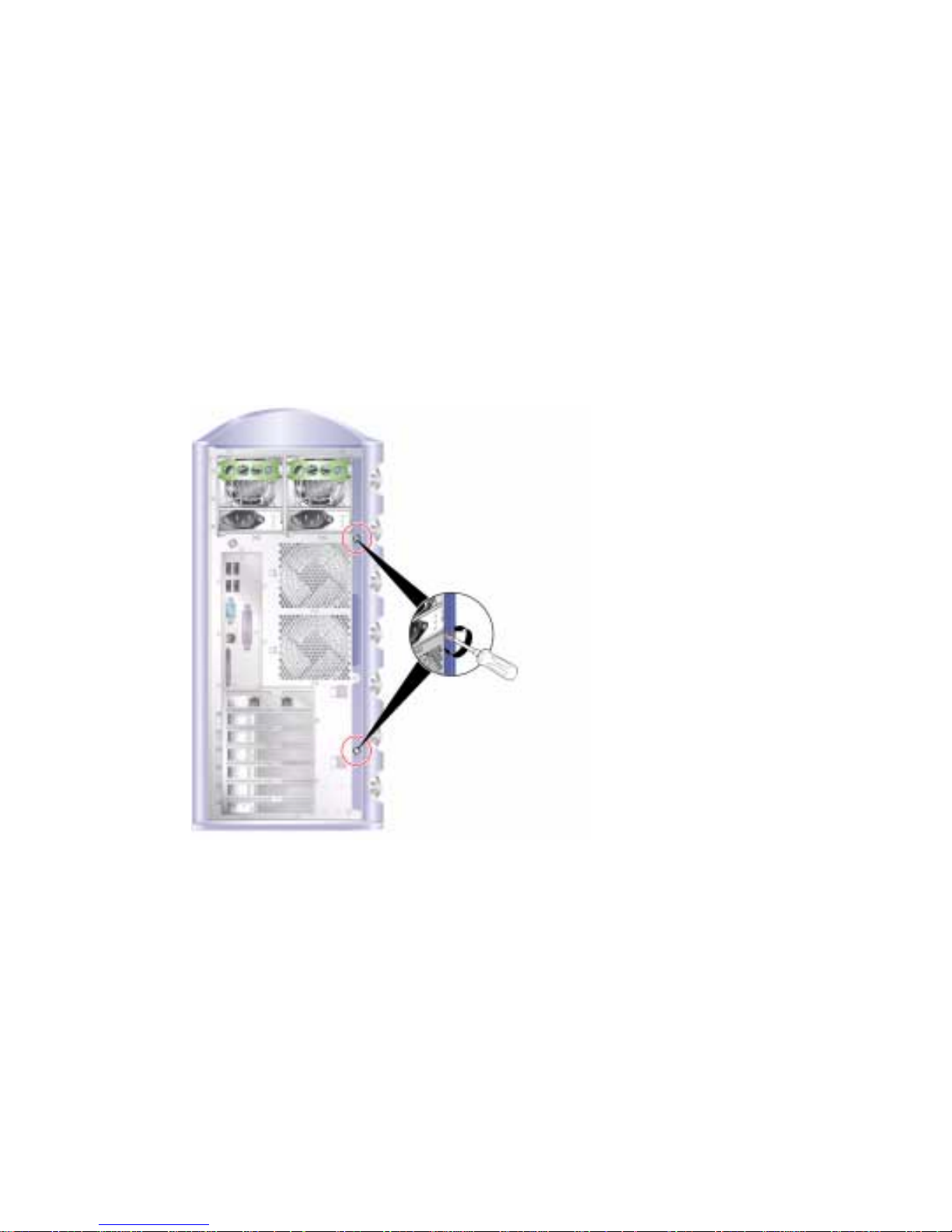
3. Unscrew the service panel retaining screws.
The service panel is retained by two captive screws on the right edge of the server’s
back panel. See
FIGURE 1-3.
FIGURE 1-3 Location of the Service Panel Retaining Screws
4. Place the server on its side.
Take care not to damage the feet.
5. Remove the service panel from the body of the server.
See
FIGURE 1-4.
8 Sun Fire V250 Server Parts Replacement Manual • September 2003
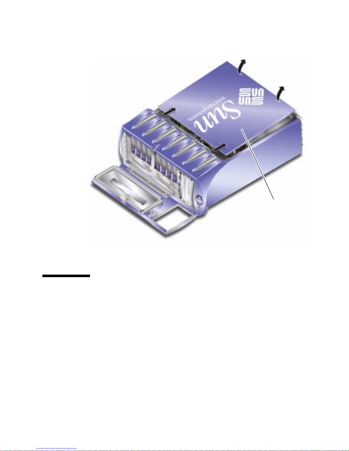
Slide service panel
away from front of
server, then lift up
FIGURE 1-4 Removing the Service Panel
Location of Components
The position of each of the server’s major components is shown in FIGURE 1-5.
Chapter 1 Parts Installation and Removal 9
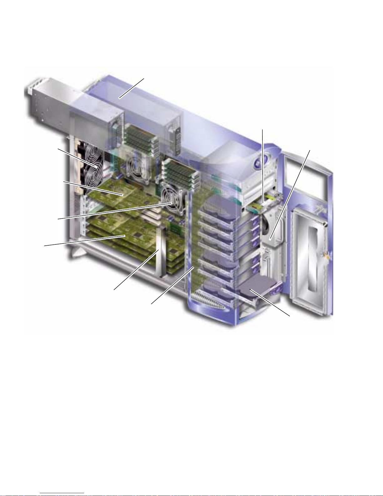
Back fans
ALOM card
CPU/CPU
fan
PCI
cards
Power supply unit/s
System configuration
card reader module
Front fan
Retaining arm for
long PCI card
SCSI backplane
FIGURE 1-5 Location of Internal Components
10 Sun Fire V250 Server Parts Replacement Manual • September 2003
Hard disk drive

User Replaceable Components
Hard Disk Drives
For information on removing a hard disk drive while the operating system is
running, see the Sun Fire V250 Server Administration Guide.
▼ To Remove a Hard Disk Drive
1. Ensure you are properly grounded.
See “Avoiding Electrostatic Discharge” on page 5.
2. Unlock and open the front door.
3. Check that the blue “OK to Remove” indicator is lit on the hard disk drive you re
going to remove.
4. Make a note of the hard disk drive bay identification number.
Put the replacement hard disk drive back into the bay from which you are removing
a hard disk drive.
Chapter 1 Parts Installation and Removal 11
5. Slide the catch at the front of the hard disk drive to the right.
This releases the handle on the front of the hard disk drive. See
FIGURE 1-6.
Slide catch to
right
Pull on
handle
Removehard
disk drive
FIGURE 1-6 Removing a Hard Disk Drive
6. Pull the hard disk drive by its handle to remove it from the server.
7. Place the hard disk drive on an antistatic bag or mat.
▼ To Insert a Hard Disk Drive
1. Ensure you are properly grounded.
See “Avoiding Electrostatic Discharge” on page 5.
2. Unlock and open the door.
3. Slide the catch on the front of the hard disk to the right.
This releases the handle on the front of the hard disk drive. The lever must be open
before you insert the hard disk drive into the server. If it is not, the hard disk drive
will not engage with the server correctly.
12 Sun Fire V250 Server Parts Replacement Manual • September 2003
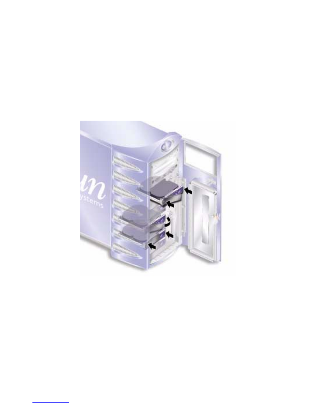
4. Make sure you are replacing the hard disk drive into the correct bay.
Refer to the note you took when you removed the hard disk drive.
5. Align the hard disk drive with the visual guides printed on both sides of each
hard disk drive bay.
6. Slide the hard disk drive into the server body until the metal lever starts to close.
This indicates that the hard disk drive has engaged with its connector in the server.
7. Press the handle so that the disk drive clicks into place.
FIGURE 1-7 Inserting a Hard Disk Drive
8. Close the door and lock it.
Power Supply Unit
Note – For information on replacing a redundant power supply unit, see the Sun
Fire V250 Server Administration Guide.
Chapter 1 Parts Installation and Removal 13

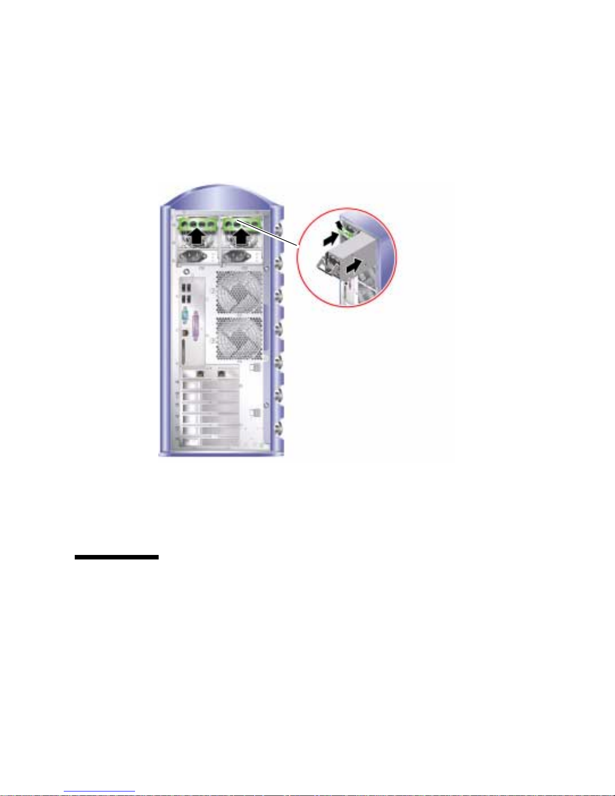
▼ To Replace a PSU
1. Turn server power off.
See “Controlling Server Power” on page 3.
2. Disconnect the power cable from the PSU.
You cannot remove a PSU unless the power cable has been disconnected.
3. Pull the PSU handle into its down position.
Inside the server, this action breaks the connection between the PSU and the power
distribution board.
FIGURE 1-8 Removing A Power Supply Unit
4. Slide the PSU out of the server body by pulling on the green PSU handle.
FIGURE 1-8.
See
5. Place the module on an antistatic bag or mat.
6. Locate the replacement PSU in the correct bay.
14 Sun Fire V250 Server Parts Replacement Manual • September 2003
7. With the handle in its down position, slide the PSU into the server’s chassis as far
as it will go.
Ensure that the handle does not return to a vertical position until the PSU is as far
into the chassis as it will go, otherwise the PSU will not engage with the power
distribution board inside the server.
FIGURE 1-9 Replacing A Power Supply Unit
8. Press the handle until it clicks home. See FIGURE 1-9.
This action engages the PSU with the power distribution board.
Service Provider Replaceable
Components
The procedures in this section are for the attention of service providers only. Users
should not carry out these procedures.
Chapter 1 Parts Installation and Removal 15

System Configuration Card Reader Module
The system configuration card reader module is replaced as a single unit and
contains:
■ system configuration card and reader
■ On/Standby button
■ operation mode switch
For information on the function of the system configuration card, see the Sun Fire
V250 Server Administration Guide .
▼ To Remove the System Configuration Card
Reader Module
1. Turn server power off.
See “Controlling Server Power” on page 3.
2. Unlock and open the door.
3. Ensure you are properly grounded.
See “Avoiding Electrostatic Discharge” on page 5.
4. Cut the security cable-tie and remove the system configuration card.
5. Keep the system configuration card, you need to install it into the replacement
reader module.
Note – The system configuration card stays with the server, unless you are replacing
a server unit.
16 Sun Fire V250 Server Parts Replacement Manual • September 2003

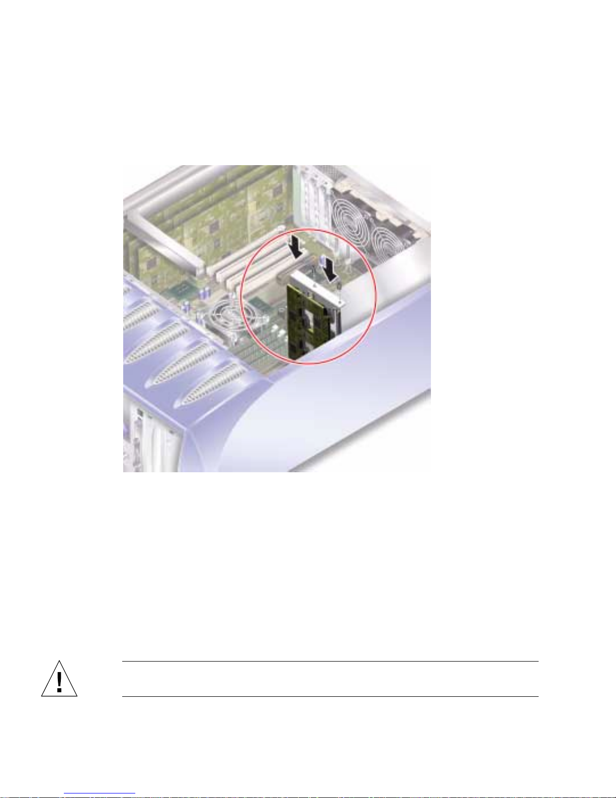
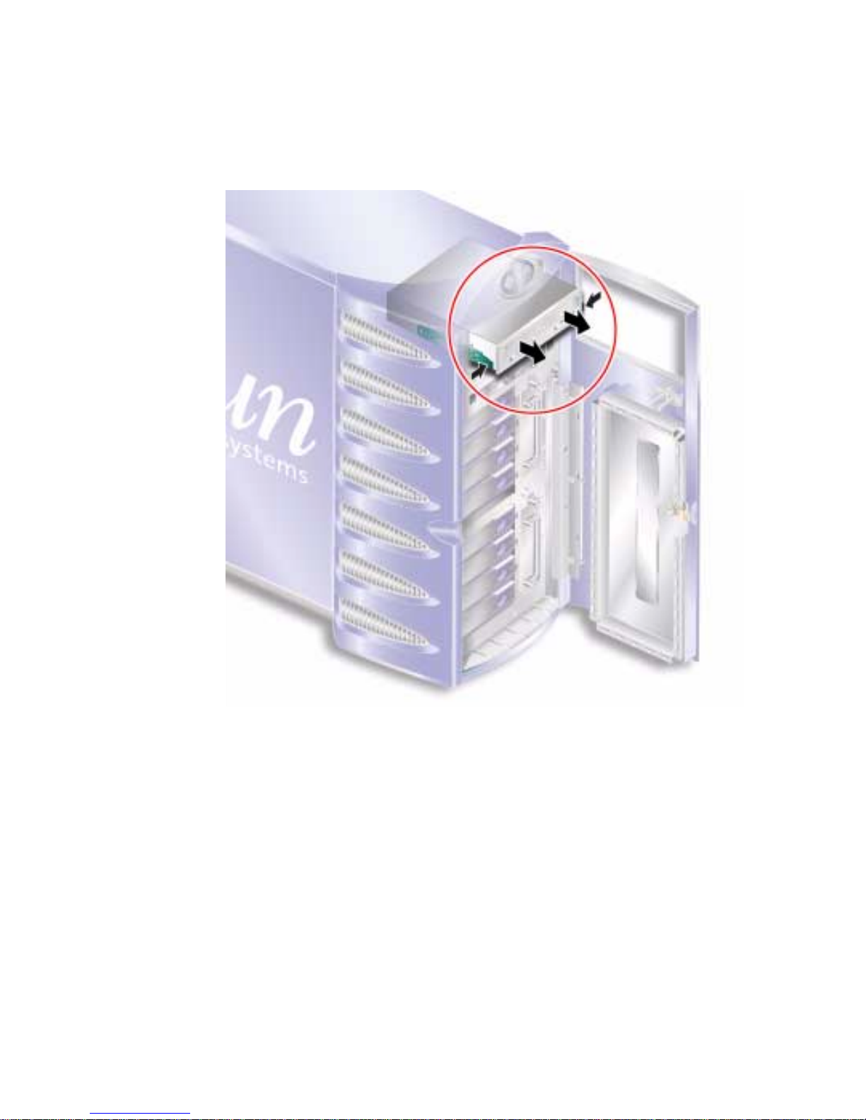
6. Unclip and slide out the system configuration card reader module.
Squeeze the two green release catches at both sides to release it. See
FIGURE 1-10.
FIGURE 1-10 Removing the System Configuration Card Reader Module
7. Place the module on an antistatic bag or mat.
▼ To Replace the System Configuration Card
Reader Module
1. Remove the existing reader module.
See “To Remove the System Configuration Card Reader Module” on page 16.
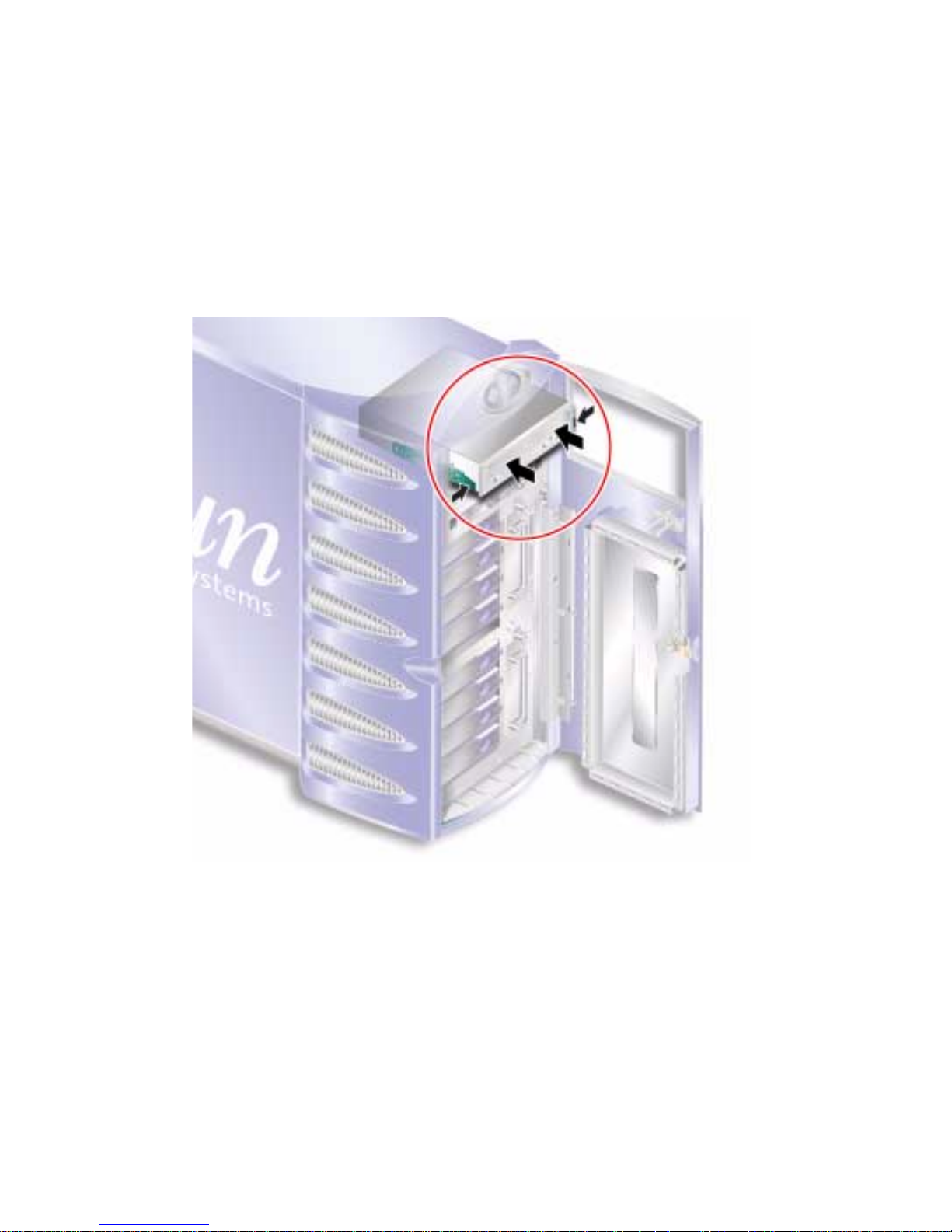
2. Slide the replacement module into its bay on the server’s front panel.
Chapter 1 Parts Installation and Removal 17

3. Slide the module in so that the clips on either side engage with the server body.
FIGURE 1-11 Replacing the System Configuration Card Reader Module
4. Replace the system configuration card.
Resecure the system configuration card with a cable tie to prevent its accidental
removal.
Power Distribution Board
The power distribution board (PDB) takes power to the server’s internal
components.
Caution – The procedures in this section are for the attention of service providers
only.
18 Sun Fire V250 Server Parts Replacement Manual • September 2003

▼ To Remove the Power Distribution Board
1. Turn server power off.
See “Controlling Server Power” on page 3.
2. Open the door.
3. Ensure you are properly grounded.
See “Avoiding Electrostatic Discharge” on page 5.
4. Disconnect the power and data cables from the DVD-ROM drive and tape drive
(if fitted).
See “Follow the instructions in this section carefully. The DVD-ROM drive contains
a laser device. Do not attempt to open the DVD-ROM drive’s enclosure or remove a
DVD-ROM drive using any procedures other than those contained in this section.”
on page 42 and “See “Avoiding Electrostatic Discharge” on page 5.” on page 38 for
further details.
5. Ensure both PSU bays are empty.
See “To Replace a PSU” on page 14.
6. Place the server on its side and remove the service panel.
See “To Remove the Service Panel” on page 8.
Chapter 1 Parts Installation and Removal 19
7. Undo the two screws securing the PDB to the chassis. (See FIGURE 1-12.)
PDB retaining
screws
FIGURE 1-12 Power Distribution Board Retaining Screws
8. Disconnect the power and data cables:
■ 2x power from the system board
■ 1x data from the SCSI backplane
9. Disconnect the wiring from the cable management bracket.
20 Sun Fire V250 Server Parts Replacement Manual • September 2003
10. Remove the power distribution board and wiring harness. See FIGURE 1-13.
FIGURE 1-13 Power Distribution Board Removal
Chapter 1 Parts Installation and Removal 21
▼ To Replace the Power Distribution Board
1. Using the two locating pins at the bottom of the PDB as a guide, locate the unit in
its correct position in the server. See
FIGURE 1-14.
FIGURE 1-14 Power Distribution Board Replacement
2. Tighten the two retaining screws.
3. Reconnect all power and data cables.
Memory
There are four memory module sockets per processor on the server’s system board.
Memory is supplied by Sun in paired DIMMS. Ensure that you use the DIMM pairs
as supplied and do not mix them.
Caution – The procedures in this section are for the attention of service providers
only.
22 Sun Fire V250 Server Parts Replacement Manual • September 2003

Memory Configuration Rules
Memory is shipped in matched pairs for use on the Sun Fire V250 server. Use
memory only in these matched pairs - do not mix memory modules.
When you install memory, follow the configuration rules below.
■ DIMMs must be identical.
■ Install two DIMMs per CPU at a time.
■ Maintain an equal amount of memory for each CPU.
■ Use a minimum of two matched DIMMs per CPU.
■ Do not mix DIMM capacities.
▼ To Add Memory
1. Turn server power off.
See “Controlling Server Power” on page 3.
2. Remove the service panel.
See “To Remove the Service Panel” on page 8.
3. Locate the correct DIMM socket.
4. Open the retaining clips.
5. Press the memory module into the DIMM socket.
Chapter 1 Parts Installation and Removal 23
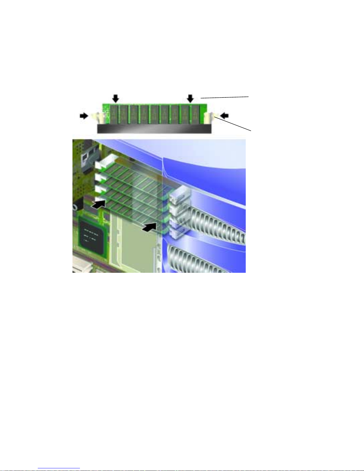
6. Apply even pressure to the top edge of the memory module until it clips into
place and the retention latches close to secure it.
See
FIGURE 1-15.
Press down evenly
on top edge of
DIMM module
Retention latch
FIGURE 1-15 Inserting a DIMM
7. Replace the service panel.
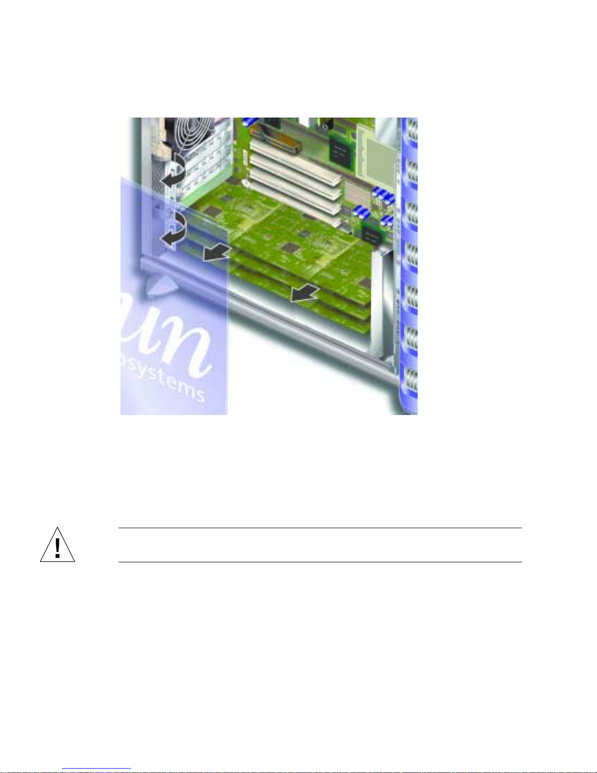
▼ To Remove Memory
1. Press down on the retention latches at the sides of the memory module.
This frees the module from its socket. See
24 Sun Fire V250 Server Parts Replacement Manual • September 2003
FIGURE 1-16.
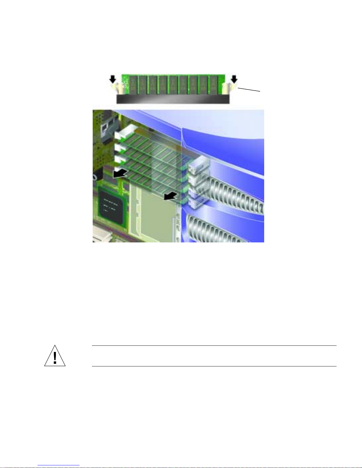
FIGURE 1-16 Removing a DIMM
Press down on latches to
release DIMM
2. Remove the memory module.
3. Replace the service panel.
Rear Cooling Fans
The Sun Fire V250 server has one cooling fan module in the back, which contains
two fans. Remove and replace the module as a single unit.
Caution – The procedures in this section are for the attention of service providers
only.
Chapter 1 Parts Installation and Removal 25
▼ To Remove the Fan Module
1. Turn server power off.
See “Controlling Server Power” on page 3.
2. Remove the service panel.
See “To Remove the Service Panel” on page 8.
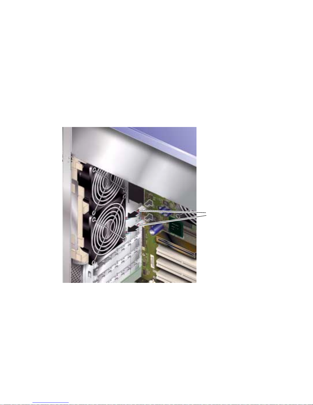
3. Disconnect the fan module power cables from the system board.
See FIGURE 1-17.
FIGURE 1-17 Disconnecting the Fan Module Power Cables
4. Unclip the fan retaining tab.
FIGURE 1-18.
See
Fan module power cables
26 Sun Fire V250 Server Parts Replacement Manual • September 2003
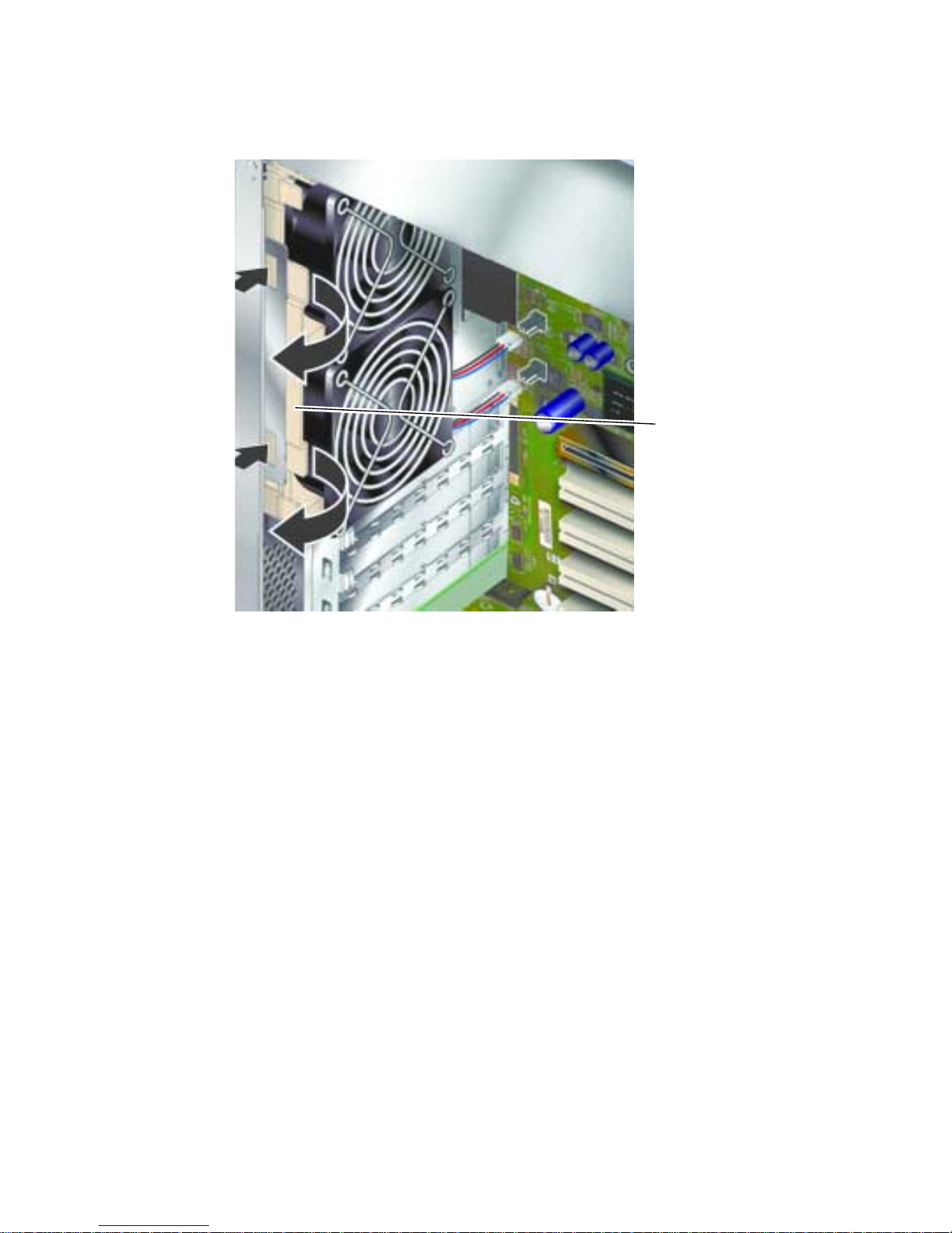
FIGURE 1-18 Removing the Fan Module
5. Rotate the fan module out and remove it from the chassis.
▼ To Replace the Fan Module
1. Insert the replacement fan module.
2. Connect the fan power cables to the system board.
3. Replace the service panel.
Fan module retaining tab
CPU Fan and Heatsink Assembly
The processor fan and heatsink assembly is replaced as one unit.
Chapter 1 Parts Installation and Removal 27
▼ To Remove a CPU Fan and Heatsink Assembly
Caution – The procedures in this section are for the attention of service providers
only.
Caution – The assembly may be hot. After disconnecting power from the server,
allow the assembly time to cool before continuing with the procedures in this
section.
1. Disconnect the server from its power source.
See “Controlling Server Power” on page 3.
2. Ensure the server is properly grounded.
See the instructions in “Avoiding Electrostatic Discharge” on page 5.
3. Remove the service panel.
See “To Remove the Service Panel” on page 8.
28 Sun Fire V250 Server Parts Replacement Manual • September 2003
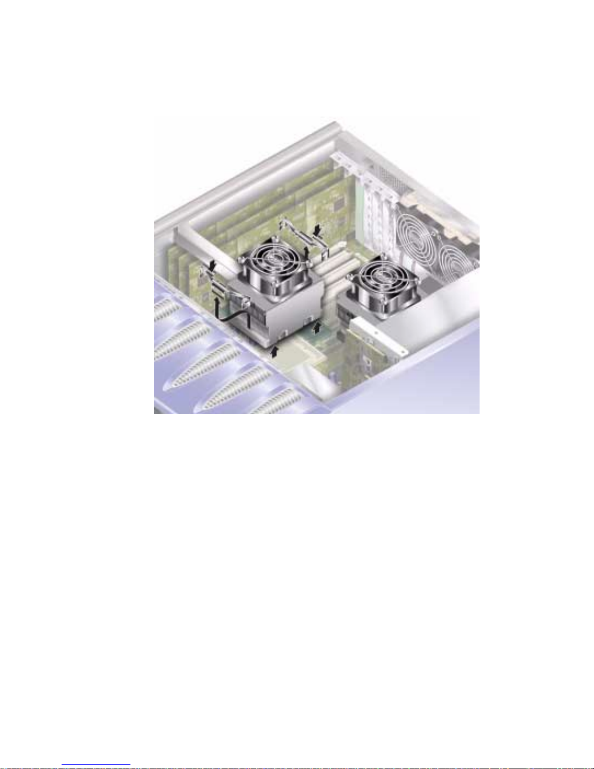
4. Disconnect the power cable for the CPU fan from the system board.
FIGURE 1-19 CPU Fan Removal
5. Press down on the tabs to release the rear clips.
6. Remove the clips from the side of the assembly.
7. Slide the heatsink assembly to release the front clips.
See
FIGURE 1-19.
8. Lift the CPU heatsink up and away from the CPU.
▼ To Replace a CPU Fan and Heatsink Assembly
1. Clip the assembly into place on the system board.
Locate the back of the assembly first.
Chapter 1 Parts Installation and Removal 29

2. Lock the retaining clips into position on both sides of the assembly.
FIGURE 1-20 Removing a Processor Fan and Heat Sink Assembly
3. Connect the CPU fan and heatsink assembly power cable.
System Board Assembly
The CPU and system board is replaced as a single assembly.
Caution – The procedures in this section are for the attention of service providers
only.
30 Sun Fire V250 Server Parts Replacement Manual • September 2003
▼ To Remove The System Board
1. Power off the server.
See “Controlling Server Power” on page 3.
2. Place the system on its side.
3. Ensure the server is properly grounded.
See “Avoiding Electrostatic Discharge” on page 5.
4. Remove the service panel.
See “To Remove the Service Panel” on page 8.
5. Disconnect all power and data cables from the system board.
■ SCSI cable to SCSI backplane
■ Data cable to SCSI backplane
■ IDE cable to DVD drive
■ Power connectors to power distribution board
FIGURE 1-21 Removing System Board Power and Data Cables
Chapter 1 Parts Installation and Removal 31

6. If any PCI cards are fitted, remove them, and place on an anti-static surface or bag.
See “PCI Cards” on page 33.
7. Remove the PCI long card holder.
See “To Remove a PCI Card” on page 35.
8. Remove the ALOM card and place it on an antistatic surface or mat.
9. Remove the fan module.
See “Rear Cooling Fans” on page 25.
10. Remove the DIMMS and place on an anti-static surface or bag.
See “To Remove Memory” on page 24.
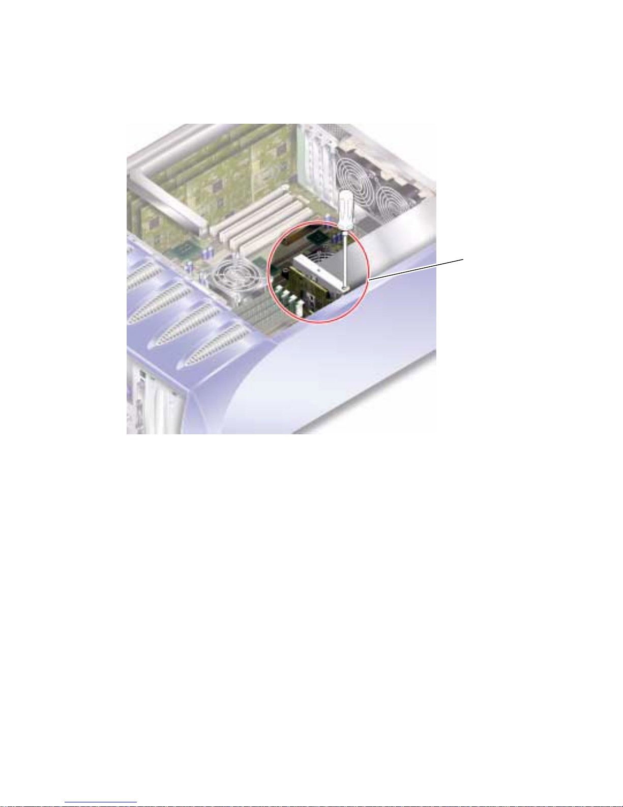
11. Loosen the system board retaining screw. See
FIGURE 1-22.
The system board is on a spring-loaded assembly which moves the board away from
the back of the server when the retaining screw is loosened.
FIGURE 1-22 Location of System Board Retaining Screw
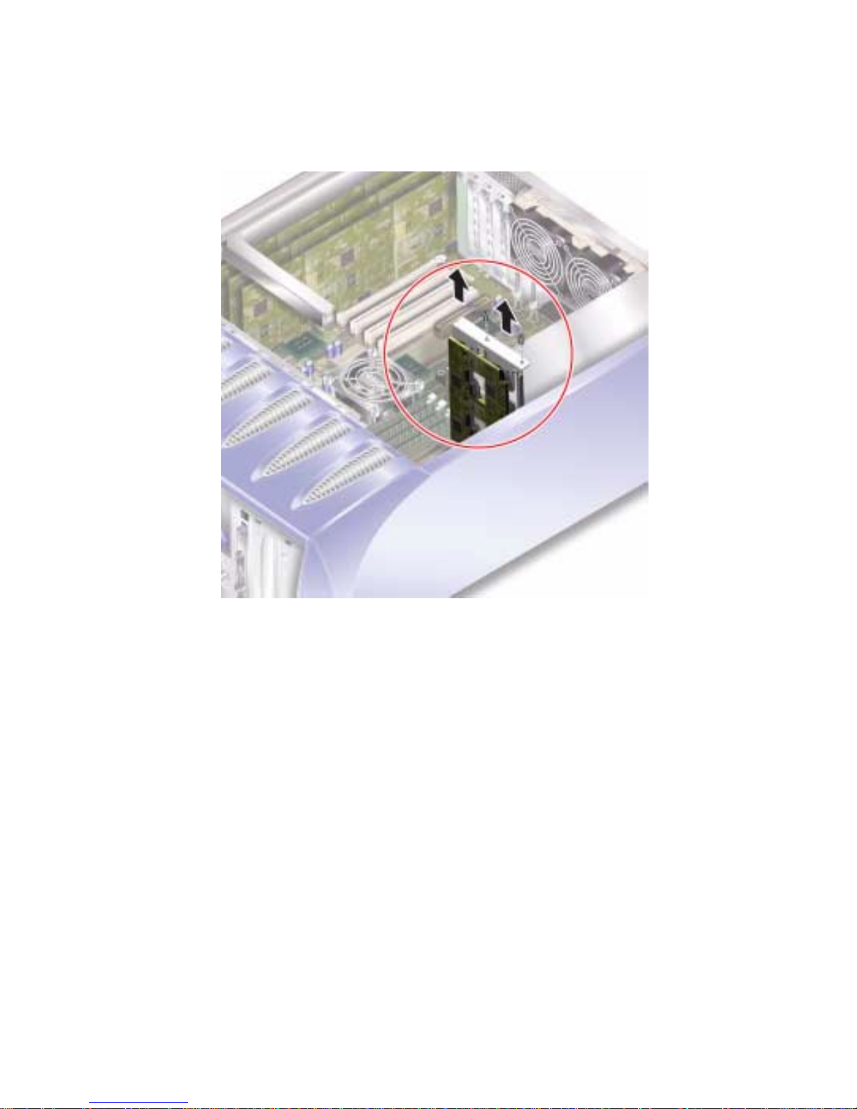
12. Slide the system board release lever towards the front of the server to release the
system board.
32 Sun Fire V250 Server Parts Replacement Manual • September 2003

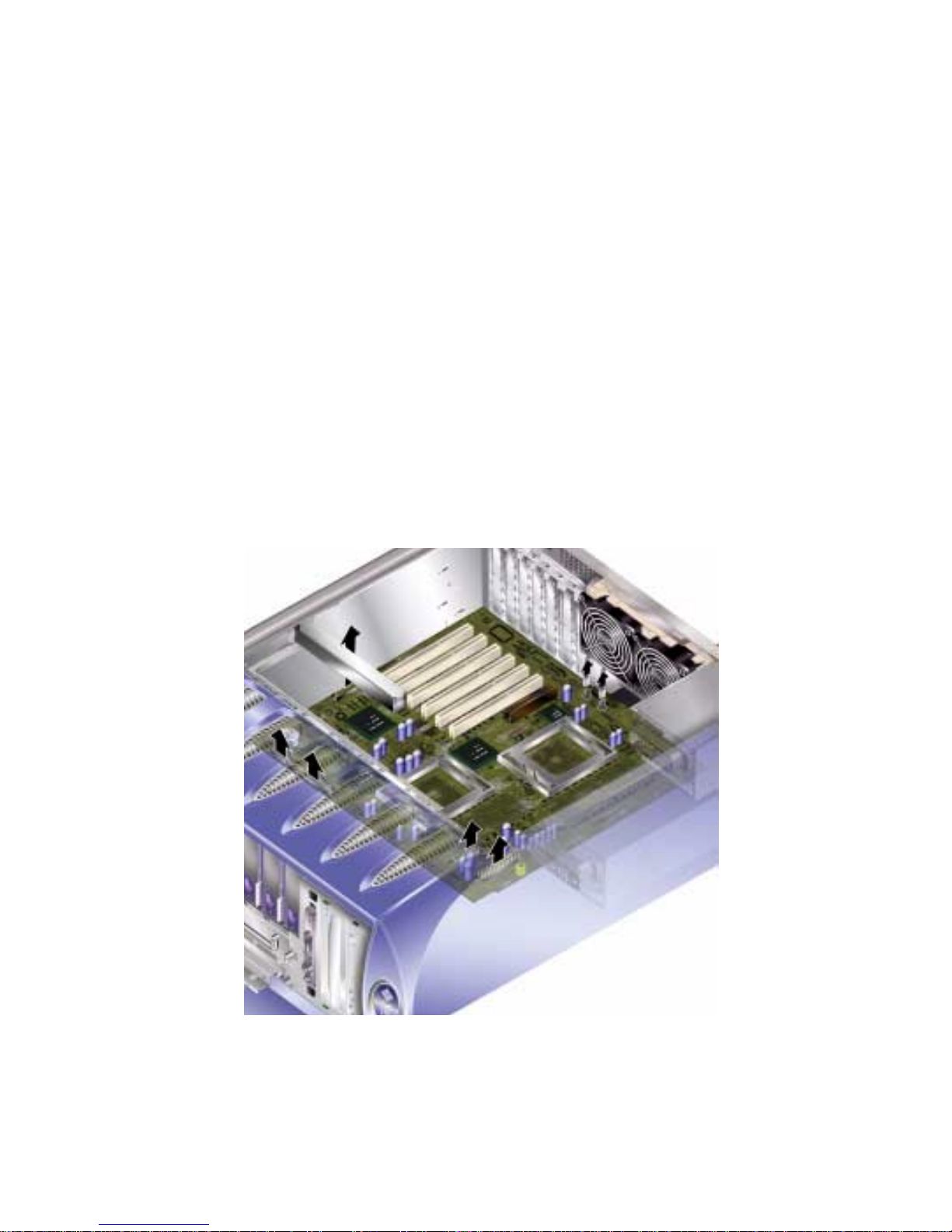
13. Holding the system board by the plastic grab-handles, lift it out of the chassis.
FIGURE 1-23.
See
FIGURE 1-23 Removing the System Board from the Chassis
PCI Cards
For information on the PCI cards that are available for the server, see the Sun Fire
V250 Server System Administration Guide.
Caution – The procedures in this section are for the attention of service providers
only.
▼ To Add a PCI Card
1. Power off the server.
See “Controlling Server Power” on page 3.
Chapter 1 Parts Installation and Removal 33

2. Ensure the server is properly grounded.
See “Avoiding Electrostatic Discharge” on page 5.
3. Place the server on its side.
4. Remove the service panel.
See “To Remove the Service Panel” on page 8.
5. Unclip the PCI retainer mechanism.
Rotate the retaining mechanism to release the PCI cards.
PCI card retaining
mechanism
PCI card release catches
FIGURE 1-24 PCI Card Retaining Mechanism
6. Place the PCI card into its slot and press it home.
7. Replace the support for long PCI cards, if necessary, and screw into place.
8. Return the PCI card retaining mechanism to its closed position.
34 Sun Fire V250 Server Parts Replacement Manual • September 2003

▼ To Remove a PCI Card
1. If removing a long PCI card, loosen the screws which secure the support for long
PCI cards.
These are located on the base of the server. See
FIGURE 1-25.
2. Slide the support towards the back of the PCI card.
FIGURE 1-25 Moving the Support for Long PCI Cards
3. Unclip the PCI retainer mechanism.
Rotate the retaining mechanism to release the PCI cards.
4. Make a note of the slot you are about to remove the PCI card from.
Chapter 1 Parts Installation and Removal 35
5. Remove the PCI card by lifting it vertically from the PCI slot.
6. Place the PCI card on an antistatic surface or bag.
SCSI Backplane
The SCSI backplane is located at the front of the internal section of the server.
Caution – The procedures in this section are for the attention of the service provider
only.
▼ To Remove the SCSI Backplane
1. Power off the server.
See “Controlling Server Power” on page 3.
36 Sun Fire V250 Server Parts Replacement Manual • September 2003
2. Ensure the server is properly grounded.
See “Avoiding Electrostatic Discharge” on page 5.
3. Remove all hard disk drives.
See “To Remove a Hard Disk Drive” on page 11. Make a note of which slot you
remove each hard disk drive from.
4. Place the server on its side.
5. Remove the service panel.
See “To Remove the Service Panel” on page 8.
6. Disconnect all power and data cables from the SCSI backplane.
The cable at the bottom of the server is secured by two retaining hooks. Bend these
back to release the cable.
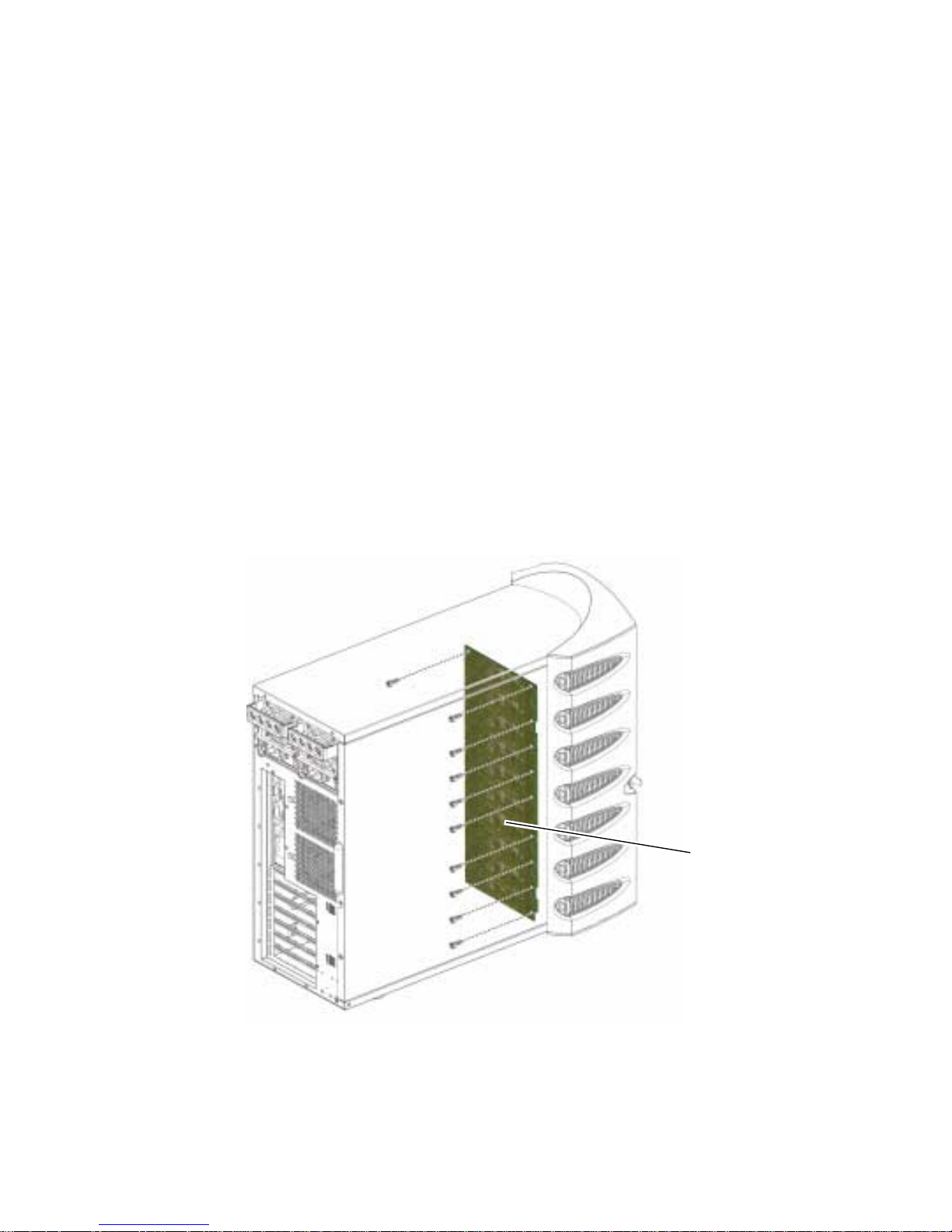
7. Unscrew the ten screws that secure the SCSI backplane to the chassis.
There are nine screws at the top edge of the board (closest to the service panel), and
one at the bottom edge (closest to the system board). See
FIGURE 1-26.
FIGURE 1-26 Location of SCSI Backplane and Fixing Screws
SCSI backplane
Chapter 1 Parts Installation and Removal 37

8. Remove the SCSI backplane from the server body and place on an antistatic
surface or bag.
▼ To Replace the SCSI Backplane
1. Locate the bottom of the SCSI backplane into the clips on the server body.
2. To help position it correctly, align the LEDs on the top edge of the SCSI backplane
with the lightpipes on the server body.
3. Replace and tighten the screws.
See
FIGURE 1-26.
4. Replace all power and data cables.
5. Replace the hard disk drives.
Refer to the notes you took when you removed the hard disk drives to ensure each
is returned to its correct bay.
Tape Drive (Optional)
The tape drive is located on the server’s front panel. If it is not installed, a blanking
plate is fitted in its place.
▼ To Install a Tape Drive
1. Turn server power off.
See “Controlling Server Power” on page 3.
2. Open the door.
3. Ensure the server is properly grounded.
See “Avoiding Electrostatic Discharge” on page 5.
38 Sun Fire V250 Server Parts Replacement Manual • September 2003

4. Remove the blanking plate. See FIGURE 1-27.
Blanking plate
FIGURE 1-27 Tape Drive Blanking Plate Removal
5. Attach the power and data cables to the tape drive module.
Chapter 1 Parts Installation and Removal 39
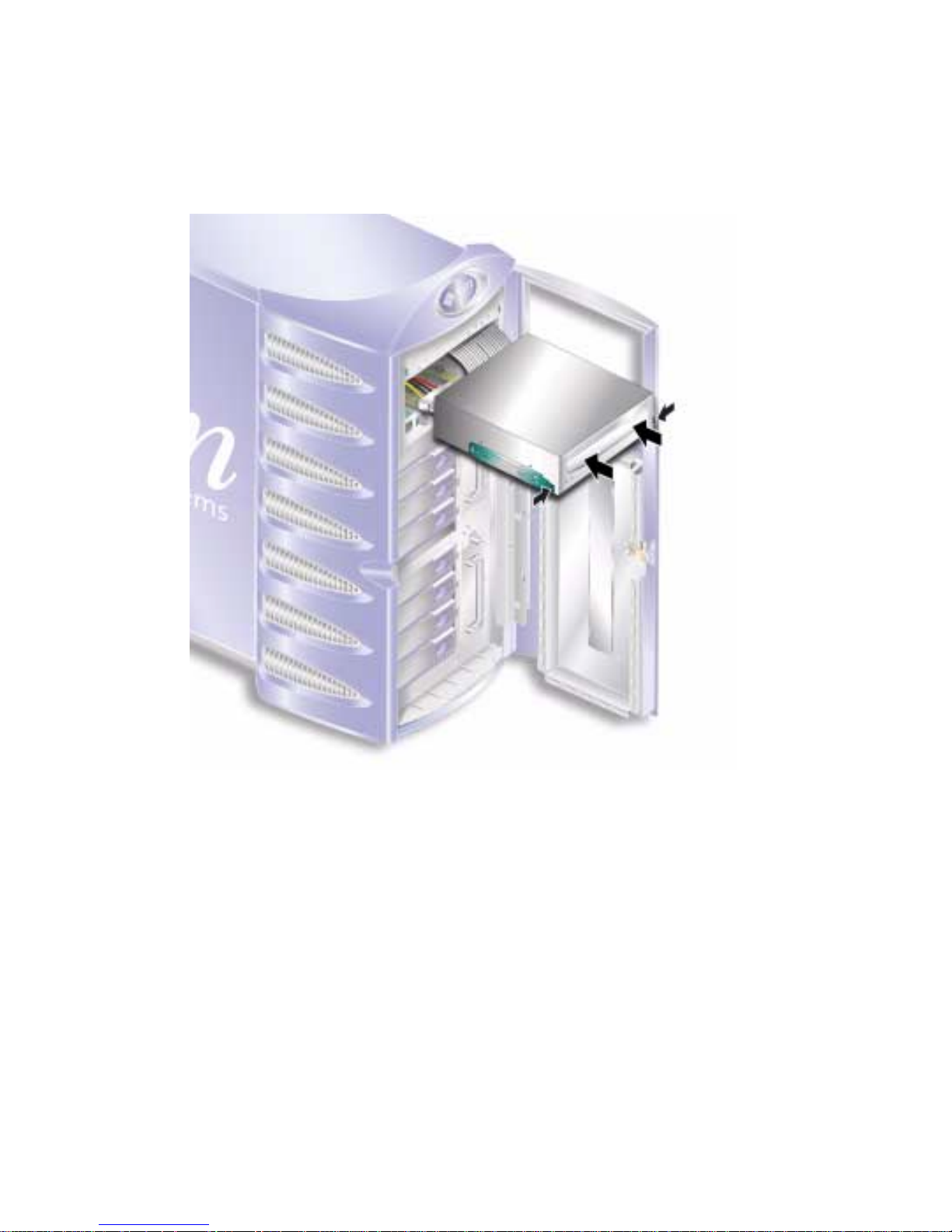
6. Slide the tape drive firmly into its slot. See FIGURE 1-28.
The green tabs secure the drive when it is inserted correctly.
FIGURE 1-28 Installing a Tape Drive Module
▼ To Remove the Tape Drive
1. Check that no media is present in the tape drive.
2. Turn server power off.
See “Controlling Server Power” on page 3.
3. Open the door.
4. Ensure the server is properly grounded.
See “Avoiding Electrostatic Discharge” on page 5.
40 Sun Fire V250 Server Parts Replacement Manual • September 2003

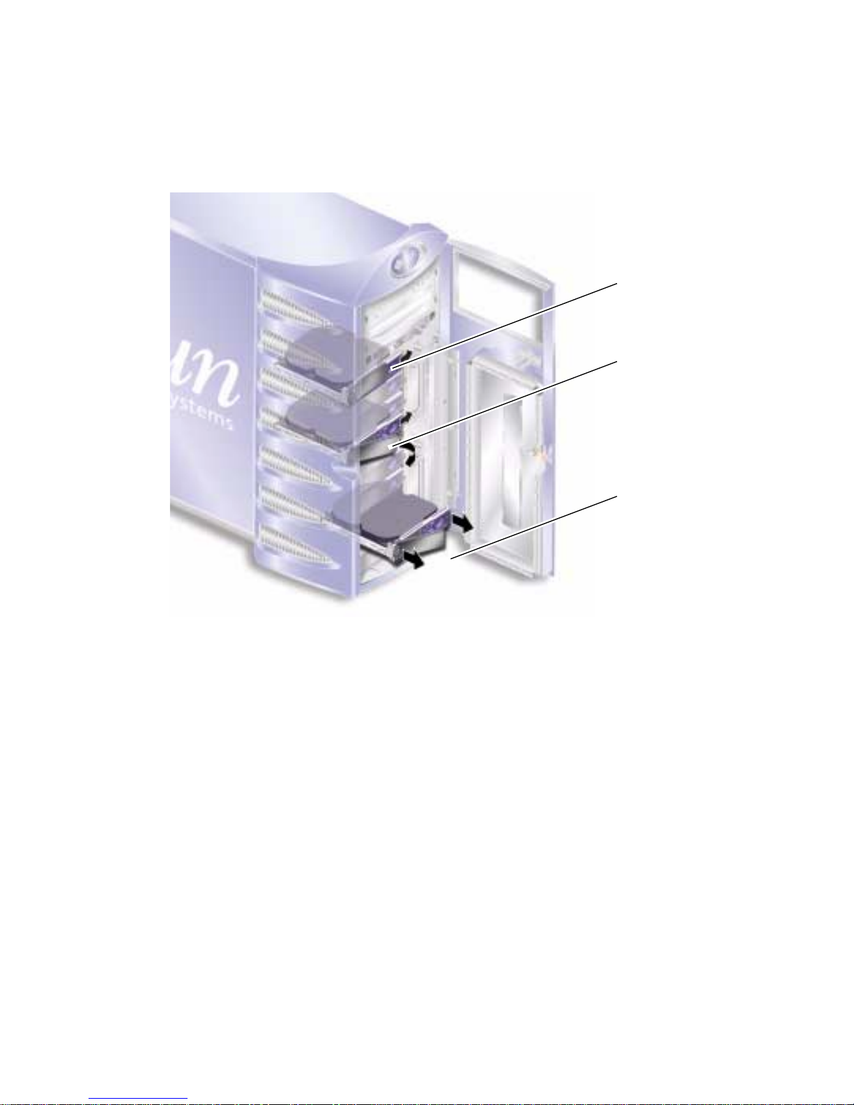
5. Release the tape drive module from the server. See FIGURE 1-29.
Squeeze the two green release catches at both sides to release it.
Tape drive
release catch
FIGURE 1-29 Removing the Optional Tape Drive
6. Slide the tape drive out of the server’s chassis.
7. Disconnect the power and data cables.
Chapter 1 Parts Installation and Removal 41
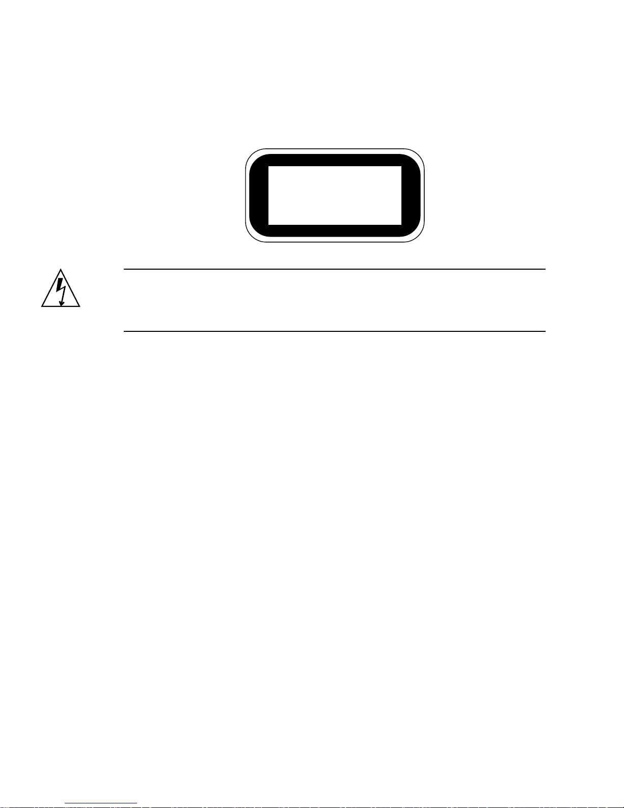
DVD-ROM Drive
Class 1 Laser Product
Luokan 1 Laserlaite
Klasse 1 Laser Apparat
Laser Klasse 1
Caution – Follow the instructions in this section carefully. The DVD-ROM drive
contains a laser device. Do not attempt to open the DVD-ROM drive’s enclosure or
remove a DVD-ROM drive using any procedures other than those contained in this
section.
▼ To Remove the DVD-ROM Drive
1. Check that no media is present in the DVD-ROM drive.
2. Turn server power off.
See “Controlling Server Power” on page 3.
3. Open the door.
4. Ensure the server is properly grounded.
See “Avoiding Electrostatic Discharge” on page 5.
42 Sun Fire V250 Server Parts Replacement Manual • September 2003
5. Unclip the DVD-ROM drive module. See FIGURE 1-30.
Squeeze the two green release catches at both sides to release it.
FIGURE 1-30 Removing the DVD-ROM Drive
6. Slide the DVD-ROM drive out of the slot.
7. Disconnect the power and data cables.
▼ To Replace the DVD-ROM Drive
1. Ensure server power is off.
See “Controlling Server Power” on page 3.
2. Open the door.
Chapter 1 Parts Installation and Removal 43
3. Ensure the server is properly grounded.
See “Avoiding Electrostatic Discharge” on page 5.
4. Connect the power and data cables to the replacement DVD-ROM drive module.
5. Slide the replacement module firmly into its slot.
The green tabs secure the drive when it is inserted correctly.
FIGURE 1-31 Replacing a DVD-ROM Drive
Front Fan Modules
There are two cooling fan modules on the front of the server, next to the hard disk
drive bays. Open the door to access the fan modules.
44 Sun Fire V250 Server Parts Replacement Manual • September 2003

▼ To Remove a Front Fan Module
1. Turn server power off.
See “Controlling Server Power” on page 3.
2. Open the door.
3. Ensure the server is properly grounded.
See “Avoiding Electrostatic Discharge” on page 5.
4. Loosen the retaining screw.
Loosen retaining
screw
FIGURE 1-32 Front Fan Module Removal
5. Open the fan module handle.
6. Grip the fan module by its handle and pull the module out of the server.
See
FIGURE 1-32.
Chapter 1 Parts Installation and Removal 45

▼ To Replace a Front Fan Module
1. Ensure server power is off.
See “Controlling Server Power” on page 3.
2. Open the door.
3. Ensure the server is properly grounded.
See “Avoiding Electrostatic Discharge” on page 5.
4. Align the fan module in the empty bay.
5. Slide the fan module all the way in to its bay.
6. Tighten the retaining screw.
FIGURE 1-33 Replacing a Front Fan Module
Battery
The battery powers the server’s clock.
46 Sun Fire V250 Server Parts Replacement Manual • September 2003
Caution – There is a risk of explosion if the battery is replaced with the wrong type.
Dispose of used batteries according to the instructions.
▼ To Replace the Battery
1. Turn server power off.
See “Controlling Server Power” on page 3.
2. Ensure the server is properly grounded.
See “Avoiding Electrostatic Discharge” on page 5.
3. Remove the service panel.
See “Service Panel” on page 7.
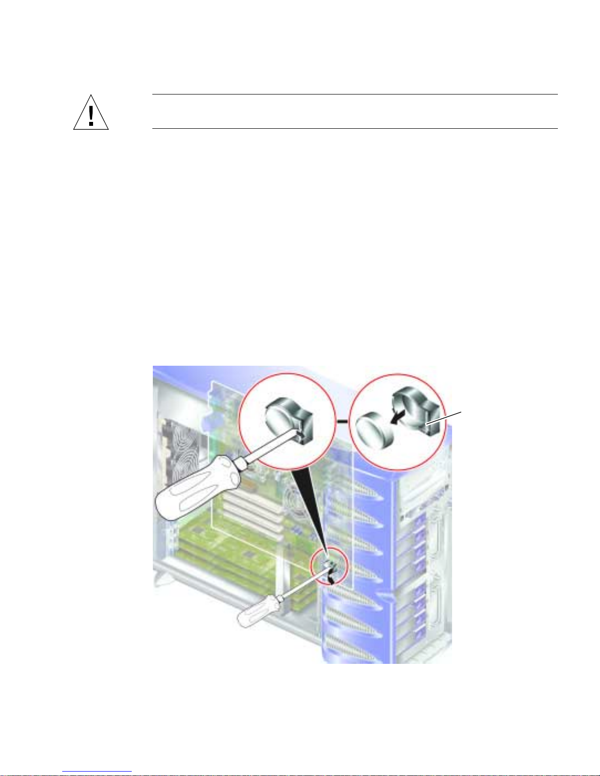
4. Unclip the battery from its housing on the system board.
Push the retaining clip to one side to release the battery.
FIGURE 1-34 Removing the Battery
Retaining clip
Chapter 1 Parts Installation and Removal 47

5. Locate the new battery in the housing and press down on it to secure it in place.
48 Sun Fire V250 Server Parts Replacement Manual • September 2003

Index
H
hard disk drive 11
I
installation
memory card reader 16, 17
L
lid 7
B
battery 46
C
cooling fans 25
CPU and system board assembly 30
CPU heatsink 27
D
disk drive
caution 4
E
electrostatic discharge (ESD) precautions 5
F
fans 25
G
grounding stud 7
M
memory 22
moving the system, precautions 4
P
PCI cards 33
power
controlling server power 3
the on/standby switch 3
power distribution board 18
R
removal
memory card reader 16, 17
system board 31
S
system configuration card
replacing the memory card reader 16, 17
system configuration card reader 16
system control switch
Diagnostics position 4
Locked position 4
Index 49

50 Sun Fire V250 Server Parts Replacement Manual • September 2003
 Loading...