


Sun Fire™ V20z and Sun Fire V40z
Servers
Server Management Guide
Sun Microsystems, Inc.
www.sun.com
Part No. 817-5249-15
July 2005, Revision A
Submit comments about this document at: http://www.sun.com/hwdocs/feedback

Copyright 2005 Sun Microsystems, Inc., 4150 Network Circle, Santa Clara, California 95054, U.S.A. All rights reserved.
Sun Microsystems, Inc. has intellectual property rights relating to technology that is described in this document. In particular, and without
limitation, these intellectual property rights may include one or more of the U.S. patents listed at http://www.sun.com/patents and one or
more additional patents or pending patent applications in the U.S. and in other countries.
This document and the product to which it pertains are distributed under licenses restricting their use, copying, distribution and
decompilation. No part of the product or of this document may be reproduced in any form by any means without prior written authorization of
Sun and its licensors, if any.
Third-party software, including font technology, is copyrighted and licensed from Sun suppliers.
Parts of the product may be derived from Berkeley BSD systems, licensed from the University of California. UNIX is a registered trademark in
the U.S. and in other countries, exclusively licensed through X/Open Company, Ltd.
Sun, Sun Microsystems, the Sun logo, Java, JumpStart, Solaris and Sun Fire are trademarks or registered trademarks of Sun Microsystems, Inc.
in the United States and in other countries.
All SPARC trademarks are used under license and are trademarks or registered trademarks of SPARC International, Inc. in the U.S. and in other
countries. Products bearing SPARC trademarks are based upon an architecture developed by Sun Microsystems, Inc.
The OPEN LOOK and Sun™ Graphical User Interface was developed by Sun Microsystems, Inc. for its users and licensees. Sun acknowledges
the pioneering efforts of Xerox in researching and developing the concept of visual or graphical user interfaces for the computer industry. Sun
holds a non-exclusive license from Xerox to the Xerox Graphical User Interface, which license also covers Sun’s licensees who implement OPEN
LOOK GUIs and otherwise comply with Sun’s written license agreements.
U.S. Government Rights—Commercial use. Government users are subject to the Sun Microsystems, Inc. standard license agreement and
applicable provisions of the FAR and its supplements.
DOCUMENTATION IS PROVIDED “AS IS” AND ALL EXPRESS OR IMPLIED CONDITIONS, REPRESENTATIONS AND WARRANTIES,
INCLUDING ANY IMPLIED WARRANTY OF MERCHANTABILITY, FITNESS FOR A PARTICULAR PURPOSE OR NON-INFRINGEMENT,
ARE DISCLAIMED, EXCEPT TO THE EXTENT THAT SUCH DISCLAIMERS ARE HELD TO BE LEGALLY INVALID.
Copyright 2005 Sun Microsystems, Inc., 4150 Network Circle, Santa Clara, California 95054, États-Unis. Tous droits réservés.
Sun Microsystems, Inc. a les droits de propriété intellectuelle relatants à la technologie qui est décrite dans ce document. En particulier, et sans la
limitation, ces droits de propriété intellectuelle peuvent inclure un ou plus des brevets américains énumérés à
http://www.sun.com/patents et un ou les brevets plus supplémentaires ou les applications de brevet en attente aux États-Unis et dans les
autres pays.
Ce produit ou document est protégé par un copyright et distribué avec des licences qui en restreignent l’utilisation, la copie, la distribution et la
décompilation. Aucune partie de ce produit ou document ne peut être reproduite sous aucune forme, par quelque moyen que ce soit, sans
l’autorisation préalable et écrite de Sun et de ses bailleurs de licence, s’il y en a.
Le logiciel détenu par des tiers, et qui comprend la technologie relative aux polices de caractères, est protégé par un copyright et licencié par des
fournisseurs de Sun.
Des parties de ce produit pourront être dérivées des systèmes Berkeley BSD licenciés par l’Université de Californie. UNIX est une marque
déposée aux États-Unis et dans d’autres pays et licenciée exclusivement par X/Open Company, Ltd.
Sun, Sun Microsystems, le logo Sun, Java, JumpStart, Solaris et Sun Fire sont des marques de fabrique ou des marques déposées de Sun
Microsystems, Inc. aux États-Unis et dans d’autres pays.
Toutes les marques SPARC sont utilisées sous licence et sont des marques de fabrique ou des marques déposées de SPARC International, Inc.
aux États-Unis et dans d’autres pays. Les produits portant les marques SPARC sont basés sur une architecture développée par Sun
Microsystems, Inc.
L’interface d’utilisation graphique OPEN LOOK et Sun a été développée par Sun Microsystems, Inc. pour ses utilisateurs et licenciés. Sun
reconnaît les efforts de pionniers de Xerox pour la recherche et le développement du concept des interfaces d’utilisation visuelle ou graphique
pour l’industrie de l’informatique. Sun détient une license non exclusive de Xerox sur l’interface d’utilisation graphique Xerox, cette licence
couvrant également les licenciées de Sun qui mettent en place l’interface d’utilisation graphique OPEN LOOK et qui en outre se conforment aux
licences écrites de Sun.
LA DOCUMENTATION EST FOURNIE «EN L’ÉTAT» ET TOUTES AUTRES CONDITIONS, DÉCLARATIONS ET GARANTIES EXPRESSES
OU TACITES SONT FORMELLEMENT EXCLUES, DANS LA MESURE AUTORISÉE PAR LA LOI APPLICABLE, Y COMPRIS NOTAMMENT
TOUTE GARANTIE IMPLICITE RELATIVE À LA QUALITÉ MARCHANDE, À L’APTITUDE À UNE UTILISATION PARTICULIÈRE OU À
L’ABSENCE DE CONTREFAÇON.
Please
Recycle

Contents
Preface xxi
How This Book Is Organized xxi
Related Documentation xxii
Accessing Sun Documentation xxii
Third-Party Web Sites xxiii
Contacting Sun Technical Support xxiii
Sun Welcomes Your Comments xxiii
1. Introduction 1
Overview 1
User Documentation 2
Acronyms 2
Server Management 4
Service Processor 4
Server-Management Interfaces 6
SNMP Integration 6
Operator Panel 8
Characteristics of Operator Panel Displays 9
User Groups 10
Users 10
iii

Passwords Files 11
Systems Management Tasks 11
Initial Setup of the SP 14
Part I: Assigning Network Settings to the SP 14
Assigning SP Network Settings Using DHCP 14
Assigning Static SP Network Settings 16
Part II: Securing the SP 18
Creating the Initial Manager Account 18
Part III: Enabling IPMI Access on the Server 20
Enabling IPMI Access on a Linux-Based Server (In-Band) 20
Enabling IPMI Access on a Solaris-Based x86 Server (In-Band) 22
Part IV: Enabling IPMI LAN Access 23
Enabling IPMI LAN Access on a Linux-Based Server (In-Band) 23
Enabling IPMI LAN Access on a Solaris-Based x86 Server (In-Band) 24
Alternate Method for Enabling IPMI LAN Access (Out-of-Band) 24
Upgrading the Linux Kernel 25
Site Integration 26
Daisy-Chaining the Servers 26
Platform Drivers and Applications 30
Updating Software 32
Selecting and Setting Up the File Server 33
Configuring and Starting the Update Server Application 34
Identifying Packages for Update 36
Updating the SP Base Package 37
Updating the SP Value-Add Package 38
Updating the BIOS 38
Updating the Diagnostics 39
Autoconfiguring the SP (Optional Method) 40
iv Sun Fire V20z and Sun Fire V40z Servers—Server Management Guide • July 2005

Determining SP and Platform Network MAC Addresses 44
Systems Management Console Features 45
Configuring Network Settings 45
Starting and Stopping the Platform OS 46
Configuring SMTP Event Notification 47
Configuring Directory Services 49
Mapping Directory Service Groups 51
Creating Keytab Files for ADS 52
ADS Server Requirements 52
ADS SP Requirements 52
Configuring Date and Time 53
Configuring SSL 54
Configuring the SSL Certificate from the SM Console 54
Monitoring System Status 56
System Events 59
Event Type Icons 62
2. IPMI Server Management 63
Intelligent Platform Management Interface 63
Baseboard Management Controller 64
Manageability 65
Functional Overview 65
IPMI Compliance and LAN Channel Access 66
Usernames and Passwords 67
Server Boot-Option Support 67
System Event Log 68
Sensors 68
Determine Sensor Presence 68
Sensor Thresholds 68
Contents v

Temperature Sensors 69
Memory Sensors for DIMMs 69
Voltage Sensors 69
Fan Sensors 70
Power-Supply Sensors 70
Management Controllers 70
Miscellaneous Sensors 70
Event Filters 72
Watchdog Timers 73
Alerting 73
Alert Policy Set Determination 73
Lights Out Management (LOM) 74
Description 74
Further Information 74
Syntax 74
Options 75
Expressions 76
IPMI Linux Kernel Device Driver 80
LAN Interface for the BMC 80
Files 81
Viewing the IPMI System Event Log 82
Clearing the IPMI System Event Log 82
IPMI Troubleshooting 83
3. SNMP Server Management 85
Simple Network Management Protocol 85
SNMP Integration 86
SNMP Management Information Base (MIB) 87
Sun Fire V20z and Sun Fire V40z Servers MIB Tree 87
vi Sun Fire V20z and Sun Fire V40z Servers—Server Management Guide • July 2005

Integrating MIBs with Third-Party Consoles 88
Configuring SNMP on Your Server 88
Out-of-Band Management Configuration 89
SNMP Agent on the Service Processor 89
Proxy Agent 90
Setting the Community Name 90
Agent X 91
Using a Third-Party MIB Browser 91
Setting Logging Options 92
SNMP Traps 93
Configuring SNMP Trap Destinations 94
Configuring SNMP Destinations 94
Server MIB Details 95
SNMP Troubleshooting 97
4. Further Management Information 99
Configuring Scripting Capabilities 99
Using Shell Scripts 100
Remote Scripting Using SSH 101
Configuring Multiple Systems for Scripting 101
Generating Host Keys 102
Creating Trusted-Host Relationships 103
Adding Public Keys 103
Generating a Host-Key Pair 104
Configuring a Windows Client for Scripting 104
Enabling SSH Access Using Trusted-Hosts 105
Generating a Hot-Key Pair on Windows 106
Enabling SSH Access Using Public Keys 107
Guidelines for Writing Server Management Command Scripts 108
Contents vii

Command Output 108
Other Tips For Best Results 109
Console Redirection Over Serial 110
Linux-based Server 110
grub 111
LILO 112
getty 113
securetty 113
Solaris-based Server 114
Enabling and Disabling BIOS Console Redirection 115
Network Share Volume (NSV) CD-ROM 116
Network Share Volume Structure 116
Serial Over LAN 117
Enabling or Disabling the SOL Feature on the Server 118
Launching an SOL Session 118
Terminating an SOL Session 119
Escape Sequences for Remote Console Terminal 119
A. Server Management Commands Summary 121
Using the ssh Protocol 122
Interactive Shell on the SP 122
Preface Text 122
Commands 123
Return Codes 124
B. Access Commands 127
Access Config-Sharing Subcommands 128
Access Enable Config-Sharing Subcommand 128
Format 128
viii Sun Fire V20z and Sun Fire V40z Servers—Server Management Guide • July 2005

Return Codes 129
Access Disable Config-Sharing Subcommand 129
Format 129
Return Codes 129
Access Get Config-Sharing Subcommand 130
Format 130
Values 130
Return Codes 131
Access Groups Subcommands 131
Access Get Group Subcommand 131
Format 131
Return Codes 132
Access Get Groups Subcommand 132
Format 132
Return Codes 132
Access Map Subcommands 133
Access Get Map Subcommand 133
Format 133
Return Codes 134
Access Map Subcommand 134
Format 134
Return Codes 135
Access Unmap Subcommand 135
Format 135
Return Codes 136
Access Directory Services Subcommands 137
Access Disable Service Subcommand 137
Format 137
Contents ix

Return Codes 138
Access Enable Service Subcommand 138
Format 138
Return Codes 139
Access Get Services Subcommand 140
Format 140
Return Codes 141
Access Trust Subcommands 142
Access Add Trust Subcommand 142
Format 142
Generating Host Keys 143
Return Codes 144
Access Delete Trust Subcommand 144
Format 144
Return Codes 145
Access Get Trusts Subcommand 146
Format 146
Return Codes 146
Access Public Key Subcommands 147
Access Add Public Key Subcommand 147
Format 147
Return Codes 148
Access Get Public Key Users Subcommand 149
Format 149
Return Codes 149
Access Delete Public Key Subcommand 150
Format 150
Return Codes 150
x Sun Fire V20z and Sun Fire V40z Servers—Server Management Guide • July 2005

Access User Subcommands 151
Access Add User Subcommand 151
Format 151
Return Codes 152
Access Delete User Subcommand 152
Format 152
Return Codes 153
Access Get Users Subcommand 153
Format 153
Return Codes 154
Access Update Password Subcommand 154
Format 154
Return Codes 155
Access Update User Subcommand 155
Format 155
Return Codes 156
C. Diagnostics Commands 157
Before You Start 158
Do Not Access the SP While Diagnostics Are Loaded 158
Known Issues 158
Benign Error Message 158
Diags Cancel Tests Subcommand 159
Format 159
Return Codes 160
Diags Get Modules Subcommand 160
Diags Get State Subcommand 162
Format 162
Return Codes 163
Contents xi

Diags Get Tests Subcommand 163
Format 163
Return Codes 164
Diags Run Tests Subcommand 164
Format 164
Return Codes 165
Diags Start Subcommand 166
Format 166
Return Codes 167
Diags Terminate Subcommand 168
Format 168
Return Codes 168
D. Inventory Commands 169
Inventory Compare Versions Subcommand 170
Format 170
Return Codes 171
Inventory Get Hardware Subcommand 171
Format 171
Return Codes 173
Inventory Get Software Subcommand 174
Format 174
Return Codes 174
Inventory Get Remote-Software Subcommand 175
Format 175
Return Codes 175
Inventory Get All Subcommand 176
Format 176
Return Codes 176
xii Sun Fire V20z and Sun Fire V40z Servers—Server Management Guide • July 2005

E. IPMI Commands 177
IPMI Disable Channel Subcommand 178
Format 178
Return Codes 178
IPMI Enable Channel Subcommand 179
Format 179
Return Codes 179
IPMI Disable PEF Subcommand 180
Format 180
Return Codes 180
IPMI Enable PEF Subcommand 181
Format 181
Return Codes 181
IPMI Get Channels Subcommand 182
Format 182
Return Codes 182
IPMI Get Global Enables Subcommand 183
Format 183
Return Codes 183
IPMI Get Sel Subcommand 183
Format 183
IPMI Clear Sel Subcommand 185
IPMI Set Global Enable Subcommand 186
Format 186
Return Codes 187
IPMI Reset Subcommand 188
Format 188
Return Codes 188
Contents xiii

F. Platform Commands 189
Platform Console Subcommands 190
Platform Console Subcommand 190
Format 190
Return Codes 193
Platform Get Console Subcommand 194
Format 194
Return Codes 195
Platform Set Console 196
Format 196
Return Codes 197
Platform OS State Subcommands 198
Platform Get OS State Subcommand 199
Format 199
Return Codes 199
Platform Set OS State Subcommands 200
Platform Set OS State Reboot 200
Platform Set OS State Boot 201
Platform Set OS State Shutdown 202
Platform Set OS State Update-BIOS 204
Platform Power State Subcommands 205
Platform Get Power State Subcommand 206
Format 206
Return Codes 206
Platform Set Power State Subcommand 207
Format 207
Return Codes 208
Platform Get Hostname Subcommand 209
xiv Sun Fire V20z and Sun Fire V40z Servers—Server Management Guide • July 2005

Format 209
Return Codes 209
Platform Get MAC Subcommand 210
Format 210
Return Codes 210
Platform Get Product ID Subcommand 211
Format 211
Return Codes 211
G. Sensor Commands 213
Sensor Get Subcommand 214
Format 214
Return Codes 216
Sensor Set Subcommand 217
Format 217
Return Codes 219
H. Service Processor Commands 221
SP Date Subcommands 222
SP Get Date Subcommand 222
Format 222
Return Codes 223
SP Set Date Subcommand 223
Format 223
Return Codes 224
SP DNS Subcommands 224
SP Disable DNS Subcommand 224
Return Codes 225
SP Enable DNS Subcommand 225
Contents xv

Format 225
Return Codes 226
SP Get DNS Subcommand 226
Format 226
Return Codes 227
SP Events Subcommands 227
SP Delete Event Subcommand 227
Format 227
Return Codes 228
SP Get Events Subcommand 228
Format 229
Return Codes 229
SP Hostname Subcommands 230
SP Get Hostname Subcommand 230
Format 230
Return Codes 231
SP Set Hostname Subcommand 231
Format 231
Return Codes 232
SP IP Subcommands 232
SP Get IP Subcommand 232
Format 233
Return Codes 233
SP Set IP Subcommand 234
Format 234
Return Codes 234
SP JNET Address Subcommands 235
SP Get JNET Subcommand 235
xvi Sun Fire V20z and Sun Fire V40z Servers—Server Management Guide • July 2005

Format 235
Return Codes 236
SP Set JNET Subcommand 236
Format 236
Return Codes 237
SP Locate Light Subcommands 238
SP Get Locatelight Subcommand 238
Format 238
Return Codes 238
SP Set Locatelight Subcommand 239
Format 239
Return Codes 239
SP Logfile Subcommands 240
SP Get Logfile Subcommand 240
Format 240
Return Codes 241
SP Set Logfile Subcommand 241
Format 241
Return Codes 242
SP Miscellaneous Subcommands 243
SP Create Test Events Subcommand 243
Format 244
Return Codes 244
SP Get MAC Address Subcommand 245
Format 245
Return Codes 245
SP Get Port 80 Subcommand 245
Format 245
Contents xvii

Return Codes 246
BIOS POST Codes 246
Boot Block Codes for Flash ROM 251
SP Autoconfigure Subcommand 253
Format 253
Return Codes 254
SP Get Status Subcommand 254
Format 254
Return Codes 255
SP Get TDULog Subcommand 255
Format 255
Return Codes 257
SP Reboot Subcommand 257
Format 257
Return Codes 258
SP Reset Subcommand 258
Format 258
Return Codes 260
SP Mount Subcommands 261
SP Add Mount Subcommand 261
Format 261
Return Codes 263
SP Delete Mount 264
Format 264
Return Codes 264
SP Get Mount Subcommand 265
Format 265
Return Codes 265
xviii Sun Fire V20z and Sun Fire V40z Servers—Server Management Guide • July 2005

SP SMTP Subcommands 266
SP Get SMTP Server Subcommand 266
Format 266
Return Codes 267
SP Set SMTP Server Subcommand 268
Format 268
Return Codes 268
SP Get SMTP Subscribers Subcommand 269
Format 269
Return Codes 270
SP Update SMTP Subscriber Subcommand 270
Format 270
Return Codes 272
SP SNMP Subcommands 272
SP Add SNMP Destination Subcommand 273
Format 273
Return Codes 273
SP Delete SNMP Destination Subcommand 274
Format 274
Return Codes 275
SP Get SNMP Destinations Subcommand 275
Format 275
Return Codes 276
SP Get SNMP Proxy Community Subcommand 276
Format 276
Return Codes 277
SP Set SNMP Proxy Community Subcommand 277
Format 277
Contents xix

Return Codes 278
SP SSL Subcommands 278
SP Disable SSL-Required Subcommand 278
Format 279
Return Codes 279
SP Enable SSL-Required Subcommand 279
Format 279
Return Codes 280
SP Get SSL Subcommand 280
Format 280
Return Codes 281
SP Set SSL Subcommand 281
Format 281
Return Codes 282
SP Update Subcommands 282
SP Update Flash All Subcommand 282
Format 283
Return Codes 284
Downgrades 284
SP Update Flash Applications Subcommand 285
Format 285
Return Codes 286
SP Update Diags Subcommand 287
Format 287
Return Codes 287
Index 289
xx Sun Fire V20z and Sun Fire V40z Servers—Server Management Guide • July 2005

Preface
This guide explains how to manage the Sun Fire™ V20z and Sun Fire V40z servers.
How This Book Is Organized
Chapter 1 provides an overview of the ways in which a user can manage the servers.
Chapter 2 describes how to manage the servers through the Intelligent Platform
Management Interface (IPMI).
Chapter 3 describes how to manage the servers through the Simple Network
Management Protocol (SNMP).
Chapter 4 provides further management information, such as how to enable
scripting capability, Console Redirection over Serial and Serial-over-LAN.
Appendix A contains an overview of the server management commands that you
can use to manage the server. Following appendixes describe each command type in
detail.
Appendix B contains detailed descriptions of Access commands.
Appendix C contains detailed descriptions of Diagnostics commands.
Appendix D contains detailed descriptions of Inventory commands.
Appendix E contains detailed descriptions of IPMI commands.
Appendix F contains detailed descriptions of Platform commands.
Appendix G contains detailed descriptions of Sensor commands.
Appendix H contains detailed descriptions of service processor (sp) commands.
xxi

Related Documentation
Application Title Part Number
Safety information Important Safety Information for Sun Hardware
Systems
Safety notices and
international compliance
certification statements
Hardware and system
software installation
Maintenance procedures
and other information
Operating-system
installation
Troubleshooting and
diagnostics
Late-breaking
information
Comparison of server
models
Sun Fire V20z and Sun Fire V40z Servers—Safety
and Compliance Guide
Sun Fire V20z and Sun Fire V40z Servers—
Installation Guide
Sun Fire V20z and Sun Fire V40z Servers—User
Guide
Sun Fire V20z and Sun Fire V40z Servers—Linux
Operating System Installation Guide
Sun Fire V20z and Sun Fire V40z Servers—
Troubleshooting Techniques and Diagnositcs Guide
Sun Fire V20z and Sun Fire V40z Servers Release
Notes
Differences Between Versions of the Sun Fire V20z
and Sun Fire V4z Servers
Accessing Sun Documentation
816-7190-xx
817-5251-xx
817-5246-xx
817-5248-xx
817-5250-xx
817-7184-xx
817-1771-xx
817-7185-xx
You can view, print, or purchase a broad selection of Sun documentation, including
localized versions, at:
http://www.sun.com/documentation
xxii Sun Fire V20z and Sun Fire V40z Servers—Server Management Guide • July 2005

Third-Party Web Sites
Sun is not responsible for the availability of third-party web sites mentioned in this
document. Sun does not endorse and is not responsible or liable for any content,
advertising, products or other materials that are available on or through such sites or
resources. Sun will not be responsible or liable for any actual or alleged damage or
loss caused by or in connection with the use of or reliance on any such content,
goods or services that are available on or through such sites or resources.
Contacting Sun Technical Support
If you have technical questions about this product that are not answered in this
document, go to:
http://www.sun.com/service/contacting
Sun Welcomes Your Comments
Sun is interested in improving its documentation and welcomes your comments and
suggestions. You can submit your comments by going to:
http://www.sun.com/hwdocs/feedback
Please include the title and part number of your document with your feedback:
Sun Fire V20z and Sun Fire V40z Servers—Server Management Guide, part number
817-5249-15
Preface xxiii

xxiv Sun Fire V20z and Sun Fire V40z Servers—Server Management Guide • July 2005

CHAPTER
1
Introduction
Overview
Strong server-management capabilities are crucial to maintaining mission-critical
servers. Advance notification of problems and rapid diagnosis and correction are
critical functions to an environment in which a few servers bear the bulk of the
workload. The Sun Fire™ V20z and Sun Fire V40z servers and their extensive
server-management capabilities lower costs by reducing failure and by potentially
eliminating hands-on management.
This document describes how to perform remote management on the Sun Fire V20z
and Sun Fire V40z servers.
The Sun Fire V20z server is an AMD Opteron processor-based, enterprise-class
one-rack-unit (1U), two-processor (2P) server. The Sun Fire V40z server is also an
AMD Opteron processor-based server, but is a three-rack-unit (3U), four-processor
(4P) server.
These servers include an embedded Service Processor (SP), flash memory, RAM, a
separate Ethernet interface and server-management software. They come equipped
with superior server-management tools for greater control and minimum total cost
of ownership. You can use the command-line interface (CLI), SNMP integration with
third-party frameworks, or IPMI to configure and manage the platform with the SP.
The dedicated SP provides complete operating-system independence and maximum
availability of server management.
1

User Documentation
For the most up-to-date user documentation, for both the Sun Fire V20z and Sun Fire
V40z servers, please visit the following Web site:
http://www.sun.com/products-n-solutions/hardware/docs/
Servers/Workgroup_Servers/Sun_Fire_V20z/index.html
This site contains the user manuals, the Release Notes and the individual guides for
each of the customer-replaceable units (CRUs).
To verify whether a document on the site is more recent than the document that you
have, refer to the final two digits (the dash-roll) of the Part Number for that
document.
Note – A document explaining the differences among the released versions of the
Sun Fire V20z and Sun Fire V40z servers is also available at this Web site. Refer to
part number (PN) 817-7185.
Acronyms
TABLE 1-1 defines the acronyms found in this document.
TABLE 1-1 Acronyms
Acronym Explanation
ACPI Advanced Configuration and Power Interface
ARP Address Resolution Protocol
BMC Baseboard Management Controller
CRU Customer-Replaceable Unit
DPC Direct Platform Control
FRU Field-Replacement Unit
grub Grand Unified Bootloader
IPMI Intelligent Platform Management Interface
KCS Keyboard Controller Style
KVM Keyboard, video and mouse
LAN Local Area Network
2 Sun Fire V20z and Sun Fire V40z Servers—Server Management Guide • July 2005

TABLE 1-1 Acronyms
Acronym Explanation
LILO Linux Loader
LOM Lights Out Management
MIB Management Information Base
RMCP Remote Management Control Protocol
SDR Sensor Data Record
SEL System Event Log
SNMP Simple Network Management Protocol
SOL Serial Over LAN
SP Service Processor
SSU System Setup Utility
SunMC Sun Management Center
UART Universal Asynchronous Receiver/Transmitter
UDP User Datagram Protocol
WAN Wide Area Network
Chapter 1 Introduction 3

Server Management
There are several options for remotely managing a Sun Fire V20z or Sun Fire V40z
server:
■ Lights Out Management (LOM) through IPMItool
■ Simple Network Management Protocol (SNMP)
Service Processor
The Sun Fire V20z and Sun Fire V40z servers include a dedicated chipset for
complete operating-system independence and maximum availability of
server-management functions. This chipset, called Service Processor (SP), is an
embedded PowerPC chip providing the following:
■ Environmental monitoring of the platform (such as temperatures, voltages, fan
speeds and panel switches)
■ Alert messages when problems occur
■ Remote control of server operations (boot, shutdown and reboot of the server’s
operating system, turning the server’s power on and off, stopping the server’s
boot process in BIOS, and upgrading the BIOS)
Note – In this document, you might see references to a Baseboard Management
Controller (BMC). A BMC is a dedicated IPMI controller. The SP found in these
servers is a general-purpose, embedded CPU that contains software to emulate a
BMC.
The SP runs an embedded version of Linux, and all the server-management
functions are developed as standard Linux applications. Its sole purpose is to
support server management; therefore, the full functionality of the operating system
is not available in the SP. Many familiar applications, such as ftp and telnet, are
not provided as they are not required to support the server-management feature set.
FIGURE 1-1 shows the back panel of the Sun Fire V20z server.
FIGURE 1-2 shows the back panel of the Sun Fire V40z server.
4 Sun Fire V20z and Sun Fire V40z Servers—Server Management Guide • July 2005

AC power connector
AC power switch
AC power indicator LED
SP 10/100
Ethernet
connectors
Platform Gigabit
Ethernet
connectors
Keyboard Mouse
connector connector
FIGURE 1-1 Sun Fire V20z Back Panel
Locate button
and LED
Vertical PCI card slots (6)
Keyboard Mouse
connector connector
Locate light
button and LED
SP reset
button
Horizontal PCI card slot
SP reset
button
SP 10/100
Ethernet
connectors
Video
connector
USB
connector
AC power connectors
(two power supplies shown)
Video
connector
USB
connector
Serial port
connector
Serial port
connector
Platform gigabit
Ethernet
connectors
FIGURE 1-2 Sun Fire V40z Back Panel
Chapter 1 Introduction 5

Server-Management Interfaces
These servers include local and remote server-management capabilities through
the
SP; the SP supports four server-management interfaces:
■ IPMI using a Keyboard Controller Style (KCS) interface and an IPMI kernel driver
(in-band)
■ IPMI over local area network (LAN) (out-of-band)
■ SNMP integration with third-party SNMP management consoles
■ Command-line-interface (CLI) LOM
Command Line Interface
Server-management capabilities are available from the command line.
See Appendix A for a list of server-management commands that you can use with
these servers, as well as a description, the command format, a list of arguments and
a list of return codes for each command.
SSH and Scripting Capabilities
A system administrator can log in to the SP using SSH and issue commands, or more
commonly, write a shell script that remotely invokes these operations.
The server-management commands enable you to efficiently manage each area of
the server. From the command line, you can write data-driven scripts that automate
the configuration of multiple machines. For example, a central management system
can cause many servers to power on and boot at a specified time, or when a specific
condition occurs.
For more information about scripting, see “Further Management Information” on
page 99.
SNMP Integration
Simple Network Management Protocol (SNMP) management provides remote access
by SNMP-compliant entities to monitor the health and status of the server. The SP
sends SNMP alerts to external management functions when warranted.
For more information about SNMP, refer to “SNMP Server Management” on
page 85.
The diagram in FIGURE 1-3 illustrates the communications paths for the different
server-management options.
6 Sun Fire V20z and Sun Fire V40z Servers—Server Management Guide • July 2005

IPMItool
Third-Party Management
Platform NICs
In-band
Platform
CLI LOM
Gigabit Ethernet
Server
SNMP-based solutions
(HP Open View,
CA UniCenter, etc.)
Service
Processor NIC
10/100 Mb/s
Out-of-band
KCS
(In-band)
SNMP
agent
IPMI management through
IPMItool
OpenIPMI (Linux)
BMC (Solaris™)
FIGURE 1-3 Diagram of the Server-Management Options
Service
Processor (SP)
Chapter 1 Introduction 7
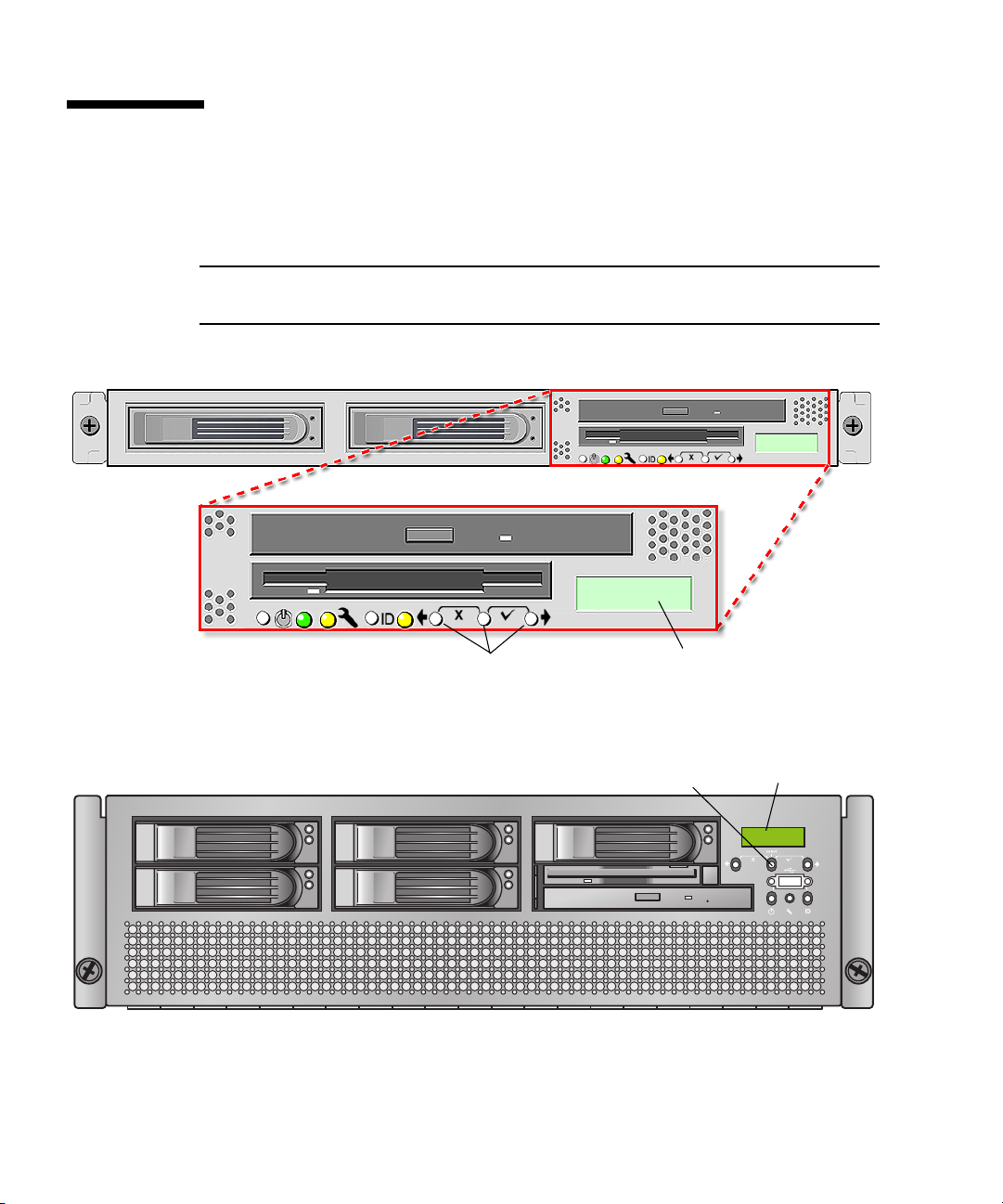
Operator Panel
You can use the operator panel to configure network settings for the SP. See
FIGURE 1-4 or FIGURE 1-5 for the operator panel location on your server.
Note – The SP defaults to Dynamic Host Configuration Protocol (DHCP)
networking if the operator panel is not interactively engaged on the first power-up.
Operator panel displayOperator-panel buttons
FIGURE 1-4 Sun Fire V20z Server Operator Panel and Buttons
Operator-panel buttons (3)
FIGURE 1-5 Sun Fire V40z Server Operator Panel and Buttons
8 Sun Fire V20z and Sun Fire V40z Servers—Server Management Guide • July 2005
Operator panel display

The operator panel displays information on the LCD display in two lines; you
respond to prompts or initiate actions using the following buttons:
TABLE 1-2 Operator-Panel Buttons
Buttons Function
Back - Move or step backward through data options for a field.
Moves through the bottom line of text, only.
Select - Move or step forward through menus and fields that
display in the top line of text and through field values for octets
that display in the bottom line of text. Confirm and save a
selected data option in that displays in the bottom line of text.
(To confirm sub-menu fields that require octets, use the Enter
button combination.)
Forward - Move or step forward through data options for a
field. Moves through the bottom line of text, only.
Enter - (Select plus Forward, the check mark combination.)
Confirms and saves a selected data option in sub-menu fields
that require octets, such as IP address, Netmask, or Gateway.
Cancel - (Back plus Select, the X combination.) Cancels the
previous confirmation and steps backward to the previous
display.
Characteristics of Operator Panel Displays
■ The Enter combination (Select plus Forward) is indicated by a check mark. This
combination confirms a data choice in sub-menu fields that require octets, such as
IP address. You must press both buttons simultaneously, and you must release
both buttons simultaneously. (In most fields, you can press Select to confirm a
data choice.)
■ The Cancel combination (Back plus Select) is indicated by an X. This combination
cancels an action, backs up in a menu, and undoes other actions, depending on
the menu. You must press both buttons simultaneously, and you must release
both buttons simultaneously.
■ For numerical value in octets, such as IP address, you can press and hold the Back
or Forward button to activate the auto-scrolling feature. This enables you to move
through the range of numbers more quickly.
■ A menu or data entry screen that displays for more than 30 seconds with no
action taken is cancelled, and the display returns to the idle/background state.
■ For every action that you confirm, feedback displays to indicate success, failure,
or that the action has been initiated.
For a complete list of the menu options on operator panel, refer to “Operator Panel”
in Chapter
1 in the Sun Fire V20z and Sun Fire V40z Servers—User Guide (817-5248).
Chapter 1 Introduction 9

User Groups
Administrators can define several different user groups, or types, on the server.
Capabilities of the different user types are defined in
For example, when you log in to the system the first time using the setup account,
the first thing you must do is set up the initial manager account so that other user
accounts can be managed. (see
“Creating the Initial Manager Account” on page 18
for details)
TABLE 1-3 User Types
User Type Capability
monitor Read-only access for sensor data and log displays.
admin All capabilities except user-account management and SP field
upgrades
manager All capabilities except SP field upgrade
service SP field upgrades
Users
There are two classes of SP users: one class of users can log on to the SP through
SSH; the other class of users can establish IPMI sessions to the SP.
TABLE 1-3.
These two classes of users are managed independently:
■ Users who are created using the IPMI interface cannot access the SP through SSH.
■ Users who log on thorugh SSH cannot access the SP through the IPMI interface.
It is possible to configure the SP so that directory-services (ADS/NFS) users can log
on to the SP through SSH. However, these directory-services users cannot log on to
the SP through the IPMI interface.
10 Sun Fire V20z and Sun Fire V40z Servers—Server Management Guide • July 2005

Passwords Files
Passwords for local, non-IPMI users are stored in a standard Linux
shadow-password file which enhances the security of the system. The hashed
passwords are in a file that is not readable by users.
Passwords for IPMI users are stored separately. The IPMI password file is not
readable by users, but passwords are stored unencrypted because of limitations
imposed by the IPMI authentication algorithms.
Systems Management Tasks
To accomplish most systems management tasks, you can use any of the systems
management tools that are included with your server.
systems management tasks, the tools that you can use to accomplish each task, and
references to sections of this document or to other resources that contain information
about how to perform the tasks.
TABLE 1-4 Systems Management Tasks
Systems
Task SM Console
Operator
Panel
Management
Command
Table 1-4 lists some common
SNMP IPMI
Analyze events Yes:,
online
help
Autoconfigure SP Ye s Yes: Yes:
Configure
directory services
Configure
external file
system
Yes: No Yes:
Yes: No Yes:
Yes,
minimal
Yes:
SM
Commands
document
SM
Commands
document
SM
Commands
document
SM
Commands
document
Ye s Yes:
SM
Command
s
document
No No
No No
No No
Chapter 1 Introduction 11

TABLE 1-4 Systems Management Tasks (Continued)
Systems
Management
Command SNMP IPMI
SM
Task SM Console
Configure
Yes: Yes: Yes:
network settings
Operator
Panel
Commands
document,
online help
Configure
scripting
capabilities
Yes: No Yes:
SM
Commands
document,
online help
Configure SMTP
event notification
Yes: No Yes:
SM
Commands
document
Configure SP date
and time settings
Yes: No Yes:
SM
Commands
document
Configure SSL Yes: No Yes:
,
No Yes:
No No
No
No
No
SM
Commands
document
Create initial
manager account
Yes: No Yes:
SM
Commands
document
Define default
system name in
Operator Panel
No Yes: Yes:
SM
Commands
document
Monitoring
system status
12 Sun Fire V20z and Sun Fire V40z Servers—Server Management Guide • July 2005
Yes:
,
online
help
Yes: Yes:
SM
Commands
document
No N/A
No No
Yes: Yes:

TABLE 1-4 Systems Management Tasks (Continued)
Systems
Management
Command SNMP IPMI
Task SM Console
Operator
Panel
Power on and off Yes:\ Yes: Yes:
SM
Commands
document
Remove software Yes:
SM
Commands
document
Run diagnostics
tests
Run
Troubleshooting
Dump Utility
Yes:
Troubleshooting
Guide
No Yes:
Troubleshooting
Guide
Yes: Yes:
SM
Commands
document
Set SP hostname Yes: Yes: Yes:
SM
Commands
document
Set up network
share volume
Yes: No Yes:
SM
Commands
document,
online help
Ye s
No
No No
No No
No No
No
Start and stop
platform OS
Yes: Yes: Yes:
SM
Commands
document,
online help
Update software Yes: Yes: Yes:
SM
Commands
document
Update SP
software
Yes: Yes: Yes:
SM
Commands
document
No Yes:
No Yes, only
the SP:
No Yes:
Chapter 1 Introduction 13

Initial Setup of the SP
This procedure describes the steps for the initial setup of the SP.
Part I: Assigning Network Settings to the SP
This section contains two alternate methods you can use to define SP network
settings:
■ “Assigning SP Network Settings Using DHCP” on page 14
■ “Assigning Static SP Network Settings” on page 16
Note – As an alternative, if no DHCP server or physical access is available, you can
configure the SP using IPMItool in conjunction with an IPMI kernel driver. To
configure your server for IPMI, perform the correct procedures for your operating
system in
Enabling IPMI LAN Access” on page 23.
Assigning SP Network Settings Using DHCP
The following procedure describes how to set the SP network settings using DHCP
from the Operator Panel. If your network does not use DHCP, or you want to assign
a static IP address to the SP, follow the instructions in
Settings” on page 16.
“Part III: Enabling IPMI Access on the Server” on page 20, then “Part IV:
“Assigning Static SP Network
Note – This procedure assumes that you have cabled the server and powered it on
as described in the Sun Fire V20z and Sun Fire V40z Servers Installation Guide. At
least one of the server’s SP ports must be connected to a LAN.
1. Press any operator-panel button on the server front panel (see FIGURE 1-6).
The LCD panel displays the first menu option:
Menu:
Server Menu
14 Sun Fire V20z and Sun Fire V40z Servers—Server Management Guide • July 2005

Back Select Forward
Press both for Cancel Press both for Enter
FIGURE 1-6 Operator-Panel Buttons
2. Press the Forward button until you reach the SP menu:
Menu:
SP menu
3. Press the Select button to display the SP menu options.
SP Menu:
Set SP IP info?
4. Press the Select button.
The following prompt appears with the default response:
SP use DHCP?
No
5. Press the Forward button to change to Yes, then press the Select button.
6. Press the Select button at the confirmation prompt.
SP use DHCP:
Yes?
The server attempts to contact a DHCP server for an IP address. When the server
receives a DHCP response, the LCD panel displays the DHCP-assigned SP IP
addresses. The SP address is configured and the server is ready for use.
Note – Depending on your network conditions, it may take five to ten seconds for
the new IP address allocated by the DHCP server to appear in the LCD panel.
7. Continue with “Part II: Securing the SP” on page 18 for instructions on creating
the initial manager account.
Chapter 1 Introduction 15

Note – A prompt appears that asks if you want to perform autoconfiguration. As an
alternative to configuring an SP manually, you can run autoconfiguration, which
replicates the configuration of one SP to another. Refer to
(Optional Method)” on page 40 for instructions on autoconfiguration.
“Autoconfiguring the SP
Assigning Static SP Network Settings
From the operator panel, follow these steps to set the SP network settings using a
static IP address. You must specify a subnet mask and default gateway. This example
uses the following sample settings:
IP Address: 10.10.30.5
Subnet Mask: 255.255.255.0
Default Gateway: 10.10.30.254
1. Press any operator-panel button on the server front panel (see FIGURE 1-6).
The LCD panel displays the first menu option:
Menu:
Server Menu
2. Press the Forward operator-panel button until you reach the SP menu:
Menu:
SP menu
3. Press the Select operator-panel button to display the SP menu options.
SP Menu:
Set SP IP info?
4. Press the Select operator-panel button. The following prompt displays with the
default response:
SP use DHCP?
No
5. Press the Select operator-panel button.
The LCD displays as follows:
SP IP Address:
0.0.0.0
6. With the cursor in the first field, increase or decrease the value using the Back or
Forward operator-panel button.
This field can hold a value between 0 and 255.
SP IP Address:
10.0.0.0
16 Sun Fire V20z and Sun Fire V40z Servers—Server Management Guide • July 2005

7. After reaching your desired value, press the Select operator-panel button to
advance the cursor to the next field.
SP IP Address:
10.0.0.0
8. Repeat Step 6 and Step 7 for each field until the desired IP address is displayed,
then use the Enter button combination to save the IP Address.
The process continues to the next network setting, the Subnet Mask. The LCD
displays as follows:
SP netmask:
255.255.255.0
9. Edit the subnet mask setting in the same manner as you did for the IP address.
When finished, use the Enter button combination to save the subnet mask.
The process continues to the next network setting, the default gateway. The LCD
displays as follows:
SP IP Gateway
10.10.30.1
10. Edit the default gateway setting in the same manner as you did for the IP address
and the subnet mask. When finished, use the Enter button combination to save the
default gateway.
The LCD displays the following confirmation prompt:
Use new IP data:
Yes?
11. Press the Select operator-panel button to use the new data, or use the Cancel
button combination to disregard.
The SP address is now configured and the server is ready for use.
Note – A prompt appears that asks if you want to perform autoconfiguration. As an
alternative to configuring an SP manually, you can run autoconfiguration, which
replicates the configuration of one SP to another. Refer to
“Autoconfiguring the SP
(Optional Method)” on page 40 for instructions on autoconfiguration.
12. Continue with “Part II: Securing the SP” on page 18.
Chapter 1 Introduction 17

Part II: Securing the SP
After you install the server and configure the SP’s network settings, you must create
the initial manager account. You can then perform initial configuration of the server
and create additional user accounts. Only the administrator who does the initial
system configuration can create the initial manager account.
Caution – The SP must be secured with a user name and password when the server
is first deployed. Failure to secure the SP can expose the server to a potential
denial-of-service attack through the SP network interface.
Creating the Initial Manager Account
A setup account is included with each server. This setup account has no password.
When you log in to the SP the first time using the setup account, you are prompted
to define the initial manager account with a password and an optional public key.
Usernames and passwords are strings that consist of any alphanumeric character,
underscore, hyphen, or period.
■ Usernames must be unique and must begin with an alphabetic character.
■ Passwords can contain any printable character and are case-sensitive.
■ A username or a password is limited to 32 characters and cannot be a null or an
empty string.
There are two methods you can use to create the initial manager account:
■ From a command line: see “Creating the Initial Account From a Command Line”
on page 18.
■ From the Server Management (SM) console: see “Creating the Initial Account
From the SM Console” on page 19.
Creating the Initial Account From a Command Line
Log in to the setup account and create the initial manager account by following this
procedure:
1. Using an SSHv1 or SSHv2 client, connect to the IP address of the SP.
2. Authenticate as the user setup with no password required.
# ssh spipaddress -l setup
3. Follow the on-screen prompts to create the initial manager account.
18 Sun Fire V20z and Sun Fire V40z Servers—Server Management Guide • July 2005

After you create the initial manager account, the setup account is deleted and you
are logged out of the server. You can then log in using the new initial manager
account, from which you can create other user accounts.
Note – If you are prompted for a password, this indicates that the SP has already
been secured with an account. If you do not know the management user name and
password, you can reset the SP from the operator panel by navigating to the SP
menu and selecting the Use
users and networks will be lost and the SP will reboot.
defaults option. Note that all current settings for
Creating the Initial Account From the SM Console
For information about the SM Console features, see “Systems Management Console
Features” on page 45.
To create the first manager account from the SM Console:
1. Enter the SP name or IP address as the URL or address in a browser, to enter the
SM Console.
Note – When you create the initial manager account, you are prompted to accept a
license agreement. After you create the initial manager account, this prompt no
longer appears.
2. At the Create Initial Manager-Level User ID screen, enter a user ID for this
account.
3. Enter a password for the account.
4. Re-enter the password to confirm.
5. Click the check mark button.
6. Use the SM Console to select initial configuration options.
After you create the initial manager-level user, the Initial Configuration Checklist
screen displays in the SM Console. This enables you to determine the options you
want for the initial setup of the SP.
The Initial Configuration Checklist is a table that lists the SM Console menu options
and the commands you use to configure each option. It also includes links to the
online help that provides instructions for each option.
Chapter 1 Introduction 19

Note – This table displays only after you create the initial manager user. Therefore,
only the administrator who initially configures the account or who resets it via the
operator panel can access it.
Note – The IP address, user name and password that you configure are referred to
in subsequent examples as the spipaddr, spuser and sppasswd.
Part III: Enabling IPMI Access on the Server
This section contains two alternate procedures: one for a Linux-based server and one
for a Solaris-based x86 server. Use the procedure that corresponds to your OS:
■ “Enabling IPMI Access on a Linux-Based Server (In-Band)” on page 20
■ “Enabling IPMI Access on a Solaris-Based x86 Server (In-Band)” on page 22
Enabling IPMI Access on a Linux-Based Server (In-Band)
1. Log in to the server and authenticate as the user root.
2. Install the custom OpenIPMI Linux kernel driver from the Sun Fire V20z and Sun
Fire V40z Servers Documentation and Support Files CD. The drivers are located
in the CD directory /support/sysmgmt/.
Browse to the OS variant installed on your server. The options are:
■ redhat/rhel3 for Red Hat Enterprise Linux, version 3 (32-bit mode uses the
architecture type “i386”; 64-bit mode uses architecture type “x86_64”)
■ suse/sles8 for SUSE Enterprise Linux, version 8 (32-bit mode uses the architecture
type “i386”; 64-bit mode uses architecture type “x86_64”)
■ suse/sles9 for SUSE Enterprise Linux, version 9 (64-bit mode uses architecture
type “x86_64”)
■ suse/suse9 for SUSE 9 Professional
3. Ensure that the kernel-source RPM is already installed on your distribution by
running the command:
# rpm -qvi kernel-source
If this utility reports that the kernel-source software package is not installed, install
the kernel-source RPM that is current for your installed Linux distribution.
■ On SUSE distributions, install the kernel-source RPM by running the command:
# yast2
20 Sun Fire V20z and Sun Fire V40z Servers—Server Management Guide • July 2005

■ On RedHat distributions, download the current kernel-source RPM to a
temporary directory (such as /tmp). Install the package by running the command:
# rpm -ivh /tmp/kernel-source*.rpm
4. Install the OpenIPMI Linux kernel driver RPM.
a. Browse to the OS variant installed on your server. The options are:
■ redhat/rhel3 for Red Hat Enterprise Linux, version 3 (32-bit mode uses the
architecture type “i386”; 64-bit mode uses architecture type “x86_64”)
■ suse/sles8 for Suse Enterprise Linux, version 8 (32-bit mode uses the
architecture type “i386”; 64-bit mode uses architecture type “x86_64”)
■ suse/sles9 for SUSE Enterprise Linux, version 9 (64-bit mode uses architecture
type “x86_64”)
■ suse/suse9 for Suse 9 Professional
b. Install the OpenIPMI RPM file by running the command:
# rpm -ivh openipmi*.rpm
Note – The kernel driver will be compiled using the kernel-source code during
installation.
5. Install IPMItool.
IPMItool is the command-line-interface (CLI) server-management client.
■ If the installed Linux distribution uses the 32-bit “i386” architecture, run the
following command:
# rpm -ivh ipmitool*.i386.rpm
■ If the installed Linux distribution uses the 64-bit “x86_64” architecture, run the
following command:
# rpm -ivh ipmitool*.x86_64.rpm
Chapter 1 Introduction 21

6. Test the IPMI kernel device driver and client application by running the
following command:
# ipmitool -I open chassis status
Successful output should look similar to the following:
"
System Power: on
Power Overload: false
Power Interlock: inactive
Main Power Fault: false
Power Control Fault: false
Power Restore Policy: unknown
Last Power Event:
Chassis Intrusion: inactive
Front-Panel Lockout: inactive
Drive Fault: false
Cooling/Fan Fault: false
"
Note – On a subsequent reboot, the IPMI kernel driver may have to be loaded with
the following command:
# modprobe ipmi_kcs_drv
Note – If you upgrade your Linux kernel, refer to “Upgrading the Linux Kernel” on
page 25.
Enabling IPMI Access on a Solaris-Based x86 Server (In-Band)
1. Log in to the server and authenticate as the user root.
2. Run the following command to install the LIPMI Solaris x86 kernel driver and the
IPMItool management control application.
These files are located on the Documentation and Support Files CD in the
/support/sysmgmt/solaris9 directory.
# pkgadd -d ./
Confirm installation of all packages when prompted.
3. Reboot the server.
22 Sun Fire V20z and Sun Fire V40z Servers—Server Management Guide • July 2005

Part IV: Enabling IPMI LAN Access
This section contains three alternate procedures: two in-band procedures and one
out-of-band procedure. Use the procedure that corresponds to your OS:
■ “Enabling IPMI LAN Access on a Linux-Based Server (In-Band)” on page 23
■ “Enabling IPMI LAN Access on a Solaris-Based x86 Server (In-Band)” on page 24
■ “Alternate Method for Enabling IPMI LAN Access (Out-of-Band)” on page 24
Enabling IPMI LAN Access on a Linux-Based Server (In-Band)
1. If the server is powered off, boot the local OS.
2. Log in to the server and authenticate as the user root.
3. Load the OpenIPMI kernel device driver (as installed in Step 3 of “Enabling IPMI
Access on a Linux-Based Server (In-Band)” on page 20).
# modprobe ipmi_kcs_drv
4. Using the following commands in IPMItool, configure the network setting for
the
SP.
Note – For more information on the syntax for IPMItool commands, refer to
“Syntax” on page 74.
# ipmitool -I open lan set 6 ipaddr ipaddr
# ipmitool -I open lan set 6 netmask netmask
# ipmitool -I open lan set 6 defgw ipaddr gwipaddr
# ipmitool -I open lan set 6 password ipmipasswd
Chapter 1 Introduction 23

Enabling IPMI LAN Access on a Solaris-Based x86 Server (In-Band)
1. If the server is powered off, boot the local OS.
2. Log in to the server and authenticate as the user root.
3. Using IPMItool, configure the network setting for the SP by using the following
commands.
Note – For more information on the syntax for IPMItool commands, refer to
“Syntax” on page 74.
# ipmitool -I lipmi lan set 6 ipaddr ipaddr
# ipmitool -I lipmi lan set 6 netmask netmask
# ipmitool -I lipmi lan set 6 defgw ipaddr gwipaddr
# ipmitool -I lipmi lan set 6 password ipmipasswd
Alternate Method for Enabling IPMI LAN Access (Out-of-Band)
1. Using an SSHv1 client or SSHv2 client, log in to the IP address of the SP.
2. Authenticate as the newly created management user (see “Part II: Securing the
SP” on page 18”).
# ssh spipaddr -l spuser
3. Enable IPMI LAN access and assign a password when prompted.
# ipmi enable channel lan
# exit
Note – This password will be referred to as ipmipasswd in subsequent examples.
4. Using IPMItool, test the IPMI LAN access.
# ipmitool -I lan -H spipaddr -P ipmipasswd chassis status
24 Sun Fire V20z and Sun Fire V40z Servers—Server Management Guide • July 2005

Upgrading the Linux Kernel
Upgrading the installed Linux kernel to a newer version requires you to recompile
the upgraded IPMI kernel device driver.
1. Install the kernel-source RPM that matches the version of the upgraded kernel
binary RPM package.
2. Log in to the server and authenticate as the user root.
3. Change to the following directory:
# cd /usr/src/kernel-modules/openipmi
4. Recompile the module by running the following commands:
# make clean
# make
# make install
5. Re-test the IPMI kernel device driver and client application by running the
following command:
# ipmitool -I open chassis status
Successful output should look similar to the following:
"
System Power: on
Power Overload: false
Power Interlock: inactive
Main Power Fault: false
Power Control Fault: false
Power Restore Policy: unknown
Last Power Event:
Chassis Intrusion: inactive
Front-Panel Lockout: inactive
Drive Fault: false
Cooling/Fan Fault: false
"
Note – On a subsequent reboot, the IPMI kernel driver may have to be loaded with
the following command:
# modprobe ipmi_kcs_drv
Chapter 1 Introduction 25

Site Integration
When deploying your server, ensure that you determine the best integration strategy
for your environment.
These servers include network connections for the SP that are separate from network
connections for the platform. This allows you to configure the server so that the SP
is connected to an isolated, management network and is not accessible from the
production network.
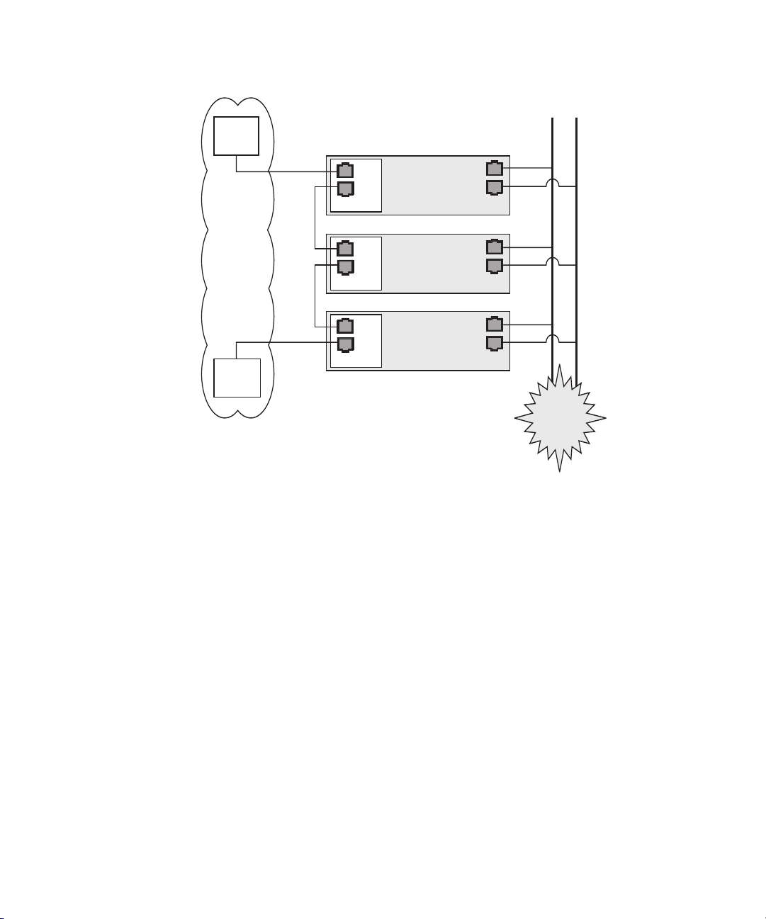
Daisy-Chaining the Servers
You can interconnect multiple servers in different daisy-chain configurations by
using the SP
FIGURE 1-8 and FIGURE 1-9. The figures also show how the servers are connected to
external LANs using the platform gigabit connectors.
Note – Sun Microsystems recommends that you use cross-over cables of at least
one meter in length for daisy-chaining the servers.
connectors to form a management LAN, as shown in FIGURE 1-7,
26 Sun Fire V20z and Sun Fire V40z Servers—Server Management Guide • July 2005
Switch 1
SP
Server 01
Server
Server 02
Server
Server 03
Server
Management
LAN
Por ts
MGMT
Cable
Cross-over
Cable
Cross-over
MGMT
MGMT
SP
Por ts
SP
Por ts
Switch 2
SP ports are
10/100 Mb/s
ports for the
Management LAN
ports for external LANs
The configuration of this Management LAN provides
redundancy at the switch level.
Platform Ports
Platform Ports
Platform Ports
Platform ports are
100/1000 Mb/s
External LANs
The
Internet!
FIGURE 1-7 Daisy-Chain Architecture with Redundancy at Switch Level on the
Management
LAN
To interconnect the servers, you must use an RJ-45 cross-over cable. Cables can be
connected to either the top or bottom SP port.
To configure servers in a daisy chain,
connect the first and last server in the chain to different switches.
In the configuration shown in FIGURE 1-7, two managed spanning-tree-capable
switches are required to redundantly connect both the top and bottom of the chain.
If the switches are not capable of spanning-tree discovery, then only connect either
to the top or the bottom of the chain, but not both.
Chapter 1 Introduction 27
Switch 1
SP
Server 01
Server
Server 02
Server
Server 03
Server
ports for external LANs
Management
LAN
Cable
Cross-over
Cable
Cross-over
SP ports are
10/100 Mb/s
ports for the
Management LAN
MGMT
MGMT
MGMT
Por ts
SP
Por ts
SP
Por ts
The configuration of this Management LAN provides
redundancy at the SP-Port level.
Platform Ports
Platform Ports
Platform Ports
Platform ports are
100/1000 Mb/s
External LANs
The
Internet!
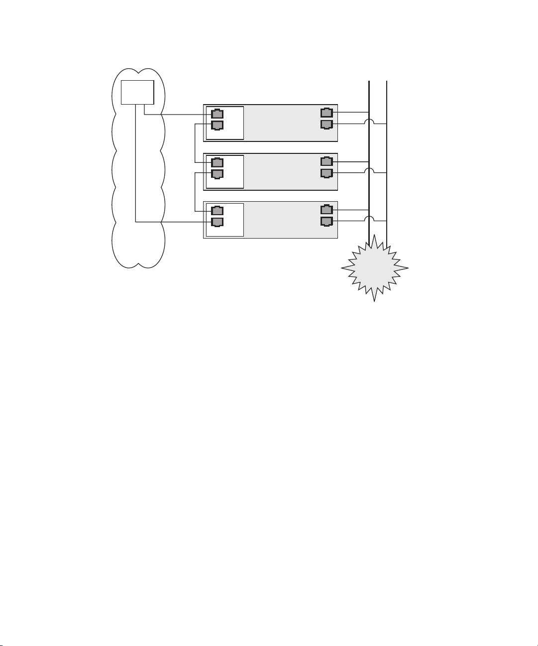
FIGURE 1-8 Daisy-Chain Architecture with Redundancy at Port Level on the
Management
LAN
To interconnect the servers, you must use an RJ-45 cross-over cable. Cables can be
connected to either the top or bottom SP port.
To configure servers in a daisy chain,
connect the first and last server in the chain to different switches.
In the configuration shown in FIGURE 1-8, a managed spanning-tree-capable switch is
required to redundantly connect both the top and bottom of the chain. If the switch
is not capable of spanning-tree discovery, then only connect either to the top or the
bottom of the chain, but not both.
28 Sun Fire V20z and Sun Fire V40z Servers—Server Management Guide • July 2005
Switch 1
Management
LAN
SP
Server 01
Por ts
MGMT
Cable
Cross-over
Cable
Cross-over
MGMT
MGMT
SP
Por ts
SP
Por ts
Server
Server 02
Server
Server 03
Server
Platform Ports
Platform Ports
External LANs
Platform Ports
SP ports are
10/100 Mb/s
ports for the
Management LAN
Platform ports are
100/1000 Mb/s
ports for external LANs
The
Internet!
The configuration of this Management LAN
does not provide redundancy.
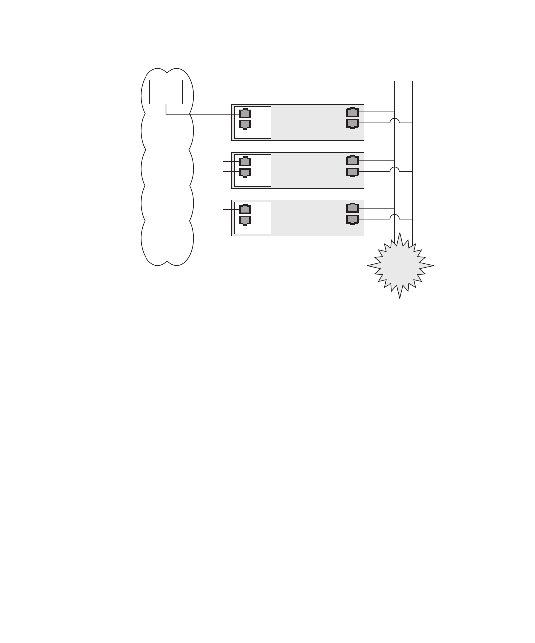
FIGURE 1-9 Daisy-Chain Architecture with No Redundancy on the Management LAN
To interconnect the servers, you must use an RJ-45 cross-over cable. Cables can be
connected to either the top or bottom SP port.
In the configuration shown in FIGURE 1-9, no redundancy is provided on the
management LAN.
Chapter 1 Introduction 29

Platform Drivers and Applications
Installation of the platform drivers and applications provides the following
capabilities:
■ Enables communication between the SP and the platform. This allows for better
control of the platform. For example, the platform can be shut down or rebooted
properly, rather than forcefully, via power downs and resets.
■ Allows the platform SNMP traps to be forwarded through the SP’s SNMP
daemon.
■ Allows the SP to monitor the health of the platform operating system when
platform difficulties occur, and to attempt to handle machine check errors.
■ Allows the SP to gather additional Vital Product Data about system components.
■ Allows the SP to gather inventory information about operating system software.
■ Allows updates to the platform BIOS from the SP.
If you do not install the Newisys platform software, these features will not be
available from the SP:
■ Ability to gracefully shutdown and reboot the platform.
■ Ability to receive notices of recoverable machine check events and ECC errors.
■ Ability to obtain platform hostname.
■ Ability to determine the current OS status.
■ Ability to determine the current version and inventory of platform software.
■ Ability to obtain CPU Vital Product Data and inventory information.
■ Ability to determine if the platform is running, via the platform heartbeat.
■ Ability to obtain platform-side SNMP information, if attached to the SP’s SNMP
server.
■ Ability to set the platform jnet address with the sp set jnet command.
The features or characteristics below are available without installation of the
platform drivers. However, they require that the SP was fully booted during the last
BIOS boot:
■ BIOS inventory information is available from the SP.
■ SP time is synchronized to the platform.
■ Optimized thermal management is available via the SP.
30 Sun Fire V20z and Sun Fire V40z Servers—Server Management Guide • July 2005

Other Important Points About Platform Software
■ When you install a platform operating system, you can configure the language
support. If you choose a language other than English, ensure that you also install
the appropriate version of third-party drivers.
■ When you install a platform operating system, you can configure the power state.
When you choose a power state, turn off Suspend and Hibernate.
■ There is a private network between the SP and the platform that supports internal
communications.
■ The link-local address 169.254.101.2 is assigned to the SP.
■ The link-local address 169.254.101.3 is assigned to the platform for
communication over this private network. These addresses are physically
assigned, not randomly generated, and probed for conflict. You can use the sp
set jnet command to change these IP addresses. The platform drivers must
be installed in order for JNET communication to work.
Chapter 1 Introduction 31

Updating Software
Note – For complete information about the menu options available through the
operator panel, refer to the Sun Fire V20z and Sun Fire V40z Servers—User Guide.
If you attempt to update the SP software using the operator panel when the
IP
address for the SP has not been set, the update fails. Ensure that the IP address
has been set prior to attempting an update. For more information, refer to the Sun
Fire V20z and Sun Fire V40z Servers Installation Guide.
A new network share volume (NSV) that is installed on your network contains
firmware packages. You can make these firmware packages available to a SP in
either of these ways:
■ The recommended method is through the Update Server, a Java application that
transfers the packages from the NSV to the SP.
■ You can update multiple SPs, simultaneously, if you use the Update Server
application.
■ You must use the Update Server application to update the SP base package.
■ Another method is to use the SP to create a network file system (NFS) mount to
the NSV. Once you accomplish this, the NSV and the packages it contains appear
to be local to the SP and are available for update.
Note – The latest BIOS version number is never the same as the latest NSV version
number, as represented in the configuration file example data lines in
and Starting the Update Server Application” on page 34.
“Configuring
32 Sun Fire V20z and Sun Fire V40z Servers—Server Management Guide • July 2005
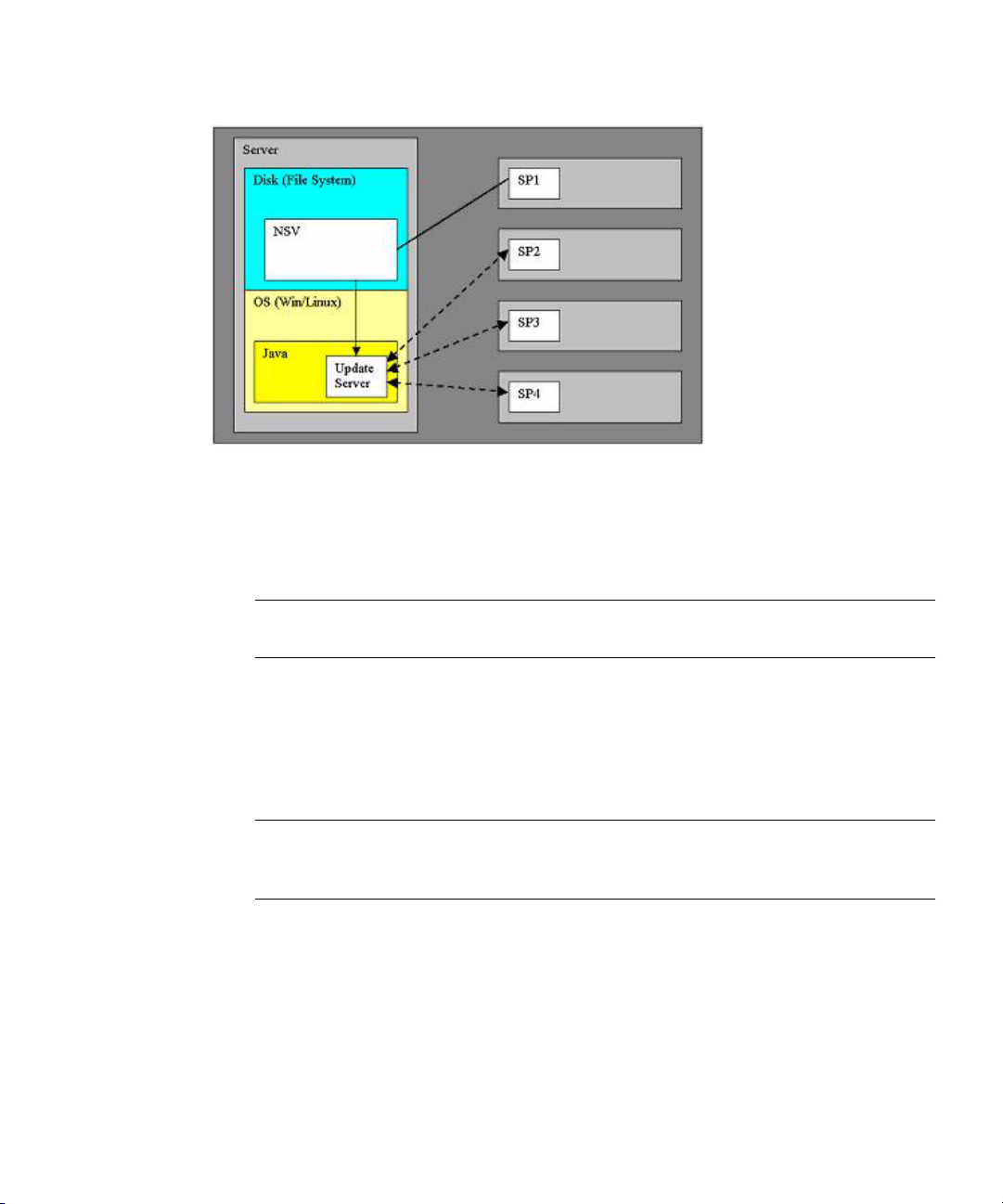
FIGURE 1-10 NSV on Network-Accessible Server
In the illustration above, the NSV has been unzipped and saved to a server that is
network-accessible by the SPs that require updated packages. SP1 has mounted the
NSV directly. SP2, SP3, and SP4 access the NSV through the Update Server.
Note – In this example, SP1 cannot update the SP base package without using the
Update Server application.
Selecting and Setting Up the File Server
Select a server that is network-accessible to the SP(s).
Note – The Update Server requires Java, and Version 1.4 or later is required. If you
plan to use the Update Server, open a shell or command prompt window and type
java –version to verify the version.
To install the NSV, follow the steps below.
1. Download the latest version or obtain the most current CD of the NSV.
2. Extract files from the compressed NSV to a location on your selected file server.
Chapter 1 Introduction 33

Note – When you unzip a compressed file on Linux, use the -a switch (for example,
unzip -a filename.zip) to force text files to convert to the target operating
system’s appropriate end-of-line termination.
A new release manifest file (releaseVersion.xml) is added to the root directory
of the NSV. See
“Network Share Volume (NSV) CD-ROM” on page 116 for details
about the NSV structure.
3. For Linux-based systems, ensure that the NSV directory has been exported.
4. Decide whether you will update using the Update Server application or by NFS
mount:
■ If you plan to use the Update Server application, go to “Configuring and Starting
the Update Server Application” on page 34.
■ If you plan to update by the NFS mount method, logon to the SP and mount the
NSV.
For example, if the IP address of the machine with the new NSV is 10.10.20.100
and you extracted the NSV files to a directory named newNSV, you would run the
command:
sp add mount –r 10.10.20.100:/newNSV -l /mnt
The NSV will then be available to the SP at /mnt/sw_images/.
Continue with “Identifying Packages for Update” on page 36.
Configuring and Starting the Update Server Application
The Update Server configuration file allows you to export multiple packages with
multiple versions to one or more SPs. To select the appropriate updates, follow the
instructions below.
1. Navigate to NVS/update_server/Vx.xx (where Vx.xx is the version you want) to
find the configuration file.
The configuration file includes example data lines, shown below.
SP_BASE V2.0.0.38 /nsv/sw_images/sp/spbase/V2.0.0.38/install.image
SP_BASE V2.0.0.40 /nsv/sw_images/sp/spbase/V2.0.0.40/install.image
SP_VALUE_ADD V2.0.0.38 /nsv/sw_images/sp/spvalueadd/V2.0.0.38/install.i
34 Sun Fire V20z and Sun Fire V40z Servers—Server Management Guide • July 2005
mage

SP_VALUE_ADD V2.0.0.40 /nsv/sw_images/sp/spvalueadd/V2.0.0.40/install.i
BIOS-X250Alpha V1.27.9 /nsv/sw_images/platform/firmware/bios/V1.27.9/bi
mage
os.sp
Note – The latest BIOS version number is never the same as the latest NSV version
number, as seen in the example, above.
Each data line contains three space-delimited values:
■ Package type: SP-BASE, SP_VALUE_ADD, BIOS
In order to support BIOS updates for several products that each require unique
BIOS firmware, the BIOS package must include the product ID. The product ID is
the value that is returned by the
platform get product-id command. It is also
found in the BIOS software manifest (swimventory.xml) that is included in an
NSV. The actual product ID used in the example above is x250 Alpha. When
you include this in the BIOS package type in the configuration file, you must add
the hyphen between BIOS and the product ID, and you must remove all spaces
from the product ID string.
■ Version, in standard version format: V[major].[minor].[patch].[build].
■ File path: actual path and filename of an update file.
2. In the configuration file, each data line is preceded by a # sign. To indicate a file
that should be updated, add the correct version number and remove the # sign at
the beginning of the data lines.
3. Navigate to the NSV folder that contains the Update Server application and start
the server via the command line:
java -jar updateServer.jar –c updateServer.config
-p <port> –l logfile.log
The updateServer.jar file is located in the update_server folder of the NSV.
■ It is recommended that you use the –l flag to create a log file.
■ Only the start and the end of an update transaction will be sent to the console.
■ Detailed information about the update process is sent to the log file, which can be
useful if you need to troubleshoot a failed update.
■ By default, the server uses port number 52708.
■ If this port number is in use already, use the optional -p flag to specify a different
port.
■ The Update Server does not start if the file is not found in the specified path.
Otherwise, the server is ready to receive update requests from any SP.
Chapter 1 Introduction 35

■ The Update Server can simultaneously accept multiple update requests from
different SPs.
Identifying Packages for Update
1. To determine which packages currently are installed on a SP, run this command
from the SP:
inventory get software
2. To determine which packages are available from a running Update Server, run
this command from the SP:
inventory get remote-software –i <server_ipaddress> -p <server_port>
Note – Some older versions of the SP do not accept the -i or -p options. These
older versions accept only these arguments: [{-a|--all}], [{-D|--Delim}],
and [{-H|--noheader}].
3. To compare currently installed packages with packages that are available on a
mounted NSV, run this command from the SP:
inventory compare versions –f <manifest_filename>
4. To compare currently installed packages with packages that are available on a
running Update Server, run this command from the SP:
inventory compare versions –i <server_ipaddress> -p <server_port>
Note – Some older versions of the SP do not accept the -i or -p options. These
older versions accept only these arguments: [{-a|--all}], [{-D|--Delim}],
and [{-H|--noheader}].
36 Sun Fire V20z and Sun Fire V40z Servers—Server Management Guide • July 2005

Updating the SP Base Package
Note – You can use the Update Server application to install this package, or you can
use the SP Update Flash option in the Operator Panel’s SP menu.
The SP base component includes the SP Value-Add component, so it also is updated
as part of this process.
Note – Because the Value-Add package can contain all feature updates in a new
release, check the Release Notes in order to determine which package you should
update.
1. Log on to the SP.
2. Execute the SP command to start the update process on the SP:
sp update flash all –i <server_ipaddress> -p <server_port> –r <version>
■ The optional -p flag indicates that the server is running on a port other than the
default port. This command pings the Update Server to determine if it is running.
If it is successful, your connection is closed when the SP reboots and the update
process begins.
■ The –r flag indicates the version of the remote package that is requested. If
LATEST is specified, the latest available version of the package is requested.
Note – Older versions of the SP do not support the -r option. If you run the sp
update flash all
command with an old version of SP, the Update Server will
automatically update your software to the most recent version.
3. Monitor the update process on the server. Messages display as the installation
process begins and ends. (More details of the update processes are in the Update
Server log file.) When the update is complete, the SP reboots with the new
version.
Note – If you update to a new version of the SP Base or Value-Add package, but do
not install the associated documentation in the NSV, the online help will not work.
After you mount the file system, check the software inventory for the version of the
SP Value-Add package. Ensure that the latest version of the documentation is
installed in the /docs directory.
Chapter 1 Introduction 37

Updating the SP Value-Add Package
The SP Value-Add component can contain all the new features in a new release.
Check the Release Notes to determine whether to update the Value-Add package or
the SP Base package.
Note – You do not have to perform this upgrade if you already updated the SP Base
package.
1. Log on to the SP.
2. Run this command:
sp update flash applications –i <server_ipaddress> -p <server_port>
-r <package_version>
Note – If you use an NFS mount, execute this command:
sp update flash applications -f <filename>
Updating the BIOS
There are three methods available for updating the BIOS, as shown in the
procedures in this section:
■ Use the Update Server application.
■ Mount the NSV.
■ Copy the BIOS image directly.
Using the Update Server Application to Update BIOS
1. Follow the steps in “Configuring and Starting the Update Server Application”
on page 34 to use the Update Server.
2. At the SP prompt, enter the command:
platform set os state update-bios -i <server_ipaddress> -p
<server_port> -r <package_version>
38 Sun Fire V20z and Sun Fire V40z Servers—Server Management Guide • July 2005

Mounting the NSV to Update BIOS
1. Logon to the SP and mount the NSV.
For example, if the IP address of the machine with the new NSV is 10.10.20.100
and you extracted the NSV files to a directory named newNSV, you would run the
command:
sp add mount –r 10.10.20.100:/newNSV
The NSV will then be available to the SP at /mnt/sw_images/.
2. At the SP prompt, enter the command:
platform set os state update-bios
/mnt/sw_images/platform/firmware/bios/Vx.x.x.x/bios.sp
Copying the BIOS Image to Update BIOS
1. Copy the BIOS image directly from the NSV to the /tmp folder on the SP file
system.
2. At the SP prompt, enter the command:
platform set os state update-bios /tmp/bios.sp
Updating the Diagnostics
The SP-based diagnostics tests are stored in the NSV and are referenced by the
/diags symbolic link in the SP. The SP software references a default version of
diagnostics. However, if a new version is released and stored on the NSV, you must
point to that new version, in order to use it.
1. Log on to the SP.
2. Mount the NSV, using the sp add mount command. For example:
sp add mount –r <NETWORK_PATH>
This mounts the directory specified by NETWORK_PATH on /mnt.
3. To verify that the mount was successful, type ls /mnt/diags. For example:
ls /mnt/diags V2.4.1.0
4. Use the sp update diags command to establish a soft link from /diags to the
desired diagnostics directory. For example:
sp update diags –p /mnt/diags/V2.4.1.0
Chapter 1 Introduction 39

5. To verify the new soft link, type ls –l /diags. For example.
ls –l /diags /diags -> /mnt/diags/V2.4.1.0
6. To verify that the diagnostics subsystem is available, run this command:
diags
This lists all the subcommands of the diags command.
Note – See the User Guide for a complete list of diagnostics modules and sample
output.
Autoconfiguring the SP (Optional Method)
Autoconfiguration replicates the majority of configuration files from an SP that has
already been configured to another SP, so that the two servers have identical
configurations, except for the host name and IP
For example, after you configure a single SP (set up users, hosts, certificates, mounts
and so on), you then run autoconfiguration on each additional SP so that the settings
are identical. In addition, if you modify the configuration of one SP, you can update
all of them by re-running autoconfiguration on each one. (For this reason, set the
IP
address of the autoconfigure server to x.x.x.1.)
address.
For a list of files that are copied or not copied during the autoconfiguration process,
see
“Files Copied in Autoconfiguration Process” on page 42.
Note – Autoconfiguration does not merge configurations, it overwrites the existing
configuration.
Note – Autoconfiguration does not work across different server platforms. That is,
you cannot configure a Sun Fire V40z SP using settings on a Sun Fire V20z SP.
Note – Autoconfiguration also does not work across different SP software versions.
The servers must be running the same version of the SP software.
40 Sun Fire V20z and Sun Fire V40z Servers—Server Management Guide • July 2005

You can start autoconfiguration either when you are prompted at the completion of
setting the IP address of the SP, or by selecting Autoconfigure from the SP menu
option on the operator panel at any time.
To perform autoconfiguration of an SP, follow these steps:
1. On the operator panel, press the Forward or Back button until the following
prompt appears.
SP Autoconfigure?
2. Press the Select button.
The following prompt appears:
SP Auto Setup?
No
3. Press the Forward or Back button to change the prompt to Yes.
For instructions on setting an IP address, refer to the Sun Fire V20z and Sun Fire V40z
Server Installation Guide.
4. Press the Select button.
The SP attempts to locate an IP address.
■ If the SP successfully locates an IP address, the following prompt appears,
displaying an IP
address for this SP:
Setup Server IP:
x.x.x.1
Where x.x.x is the first three octets of the SP IP address. For example, if the
address is 10.10.30.19, the address that displays in the prompt appears as
10.10.30.1.
In this case, press the Select operator-panel button to start autoconfiguration.
■ If the SP does not locate an IP address, the following message appears:
Unable to get
SP IP address
In this case, you must manually enter an IP address before you press the Select
operator-panel button to start autoconfiguration.
5. Wait until the autoconfiguration is complete, at which point the SP automatically
reboots.
The following message displays when autoconfiguration is running.
SP AutoConfigure
in progress
Note – If the autoconfiguration is unsuccessful, a failure message displays. Press
any button to clear it.
Chapter 1 Introduction 41

Files Copied in Autoconfiguration Process
TABLE 1-5 provides the list of files copied during the Autoconfiguration process.
TABLE 1-6 provides the list of files that are not copied during the process.
The autoconfiguration process performs some safety checks on some files.
■ The passwd and shadow files are processed to pass only user accounts that can
be created through the access command.
■ The root account, enabled or not, is not cloned.
■ The fstab file passes only the mount point information for /mnt.
■ Only the ssh key files for those users who are authorized on the system are
replicated on the target. Key files for users who have been removed from the
target are removed.
■ Under SP software version 2.1.*, the files IPMIConfig.xml and
SystemStruct.xml are copied only if the product ID and board revision are
identical. These files cannot be transferred from a server running SP software
version 2.1.* to a server running SP software version 2.2.*, and vice-versa.
All files are transferred between the two hosts through an SSL socket connection.
This is true even if the option ssl_not_enforced is enabled.
TABLE 1-5 Files Copied in Autoconfiguration Process
File Purpose
/pstore/passwd User account list
/pstore/group User group list
/pstore/shadow User account passwords (local users only)
/pstore/fstab /mnt filesystem information
/pstore/smb.creds User/password information for SMB mount
/pstore/evcfg.xml Event manager configuration file
/pstore/seccfg.xml Security manager configuration file
/pstore/oppanelcfg.xml Operator-panel configuration file
/pstore/snmpd.conf.template SNMP configuration file
/pstore/snmp_proxy_community.txt SNMP configuration file
/pstore/resolv.conf Directory Name Service configuration
/pstore/jnet_config JNET network configuration
/pstore/krb5.keytab Kerberos authentication configuration (for
Windows authentication)
/pstore/ssl_not_enforced Disables SSL requirement for SM GUI console
(Note: SM GUI console not available on the Sun
Fire V20z and Sun Fire V40z servers)
42 Sun Fire V20z and Sun Fire V40z Servers—Server Management Guide • July 2005

TABLE 1-5 Files Copied in Autoconfiguration Process (Continued)
File Purpose
/pstore/user_ssl_server.key,.crt SSL key and certification for SM GUI console
(Note: SM GUI console not available on the Sun
Fire V20z and Sun Fire V40z servers)
/pstore/ssh_known_hosts SSH host keys (trusted hosts)
/pstore/ssh_authorized_keys/* SSH user keys (trusted users)
/pstore/IPMI/IPMIConfig.xml IPMI configuration
/pstore/IPMI/ipmiusers IPMI user list
(Note: Not copied by servers or clients running
SP
software version 2.1.*)
/pstore/SystemsStruct.xml User-modified sensor thresholds
/dev/mtd/custom Custom configuration area
Chapter 1 Introduction 43

TABLE 1-6 Files Not Copied in Autoconfiguration Process
File Purpose
/pstore/mc.conf Machine check configuration
/pstore/hostname Local SP hostname
/pstore/ifcfg2-eth0 Local SP IP configuration
/pstore/dimm.map Platform DIMM configuration
/pstore/edstatefile Local SP event log
/pstore/emstatefile Local SP event log
/pstore/hwinventory Hardware inventory list
/pstore/inv_manifests/* Software inventory list
/pstore/snmpd.conf SNMP engine unique ID
/pstore/sp_uuid SP unique ID
/pstore/ssh/ssh_host* SSH host keys
/pstore/IPMI/sdrr IPMI sensor data repository
/pstore/IPMI/SEL IPMI sensor event log
Determining SP and Platform Network MAC Addresses
Use the following commands if you need to determine the MAC address of your
server’s SP or platform:
# ssh spipaddress -l spusername sp get mac
# ssh spipaddress -l spusername platform get mac
44 Sun Fire V20z and Sun Fire V40z Servers—Server Management Guide • July 2005
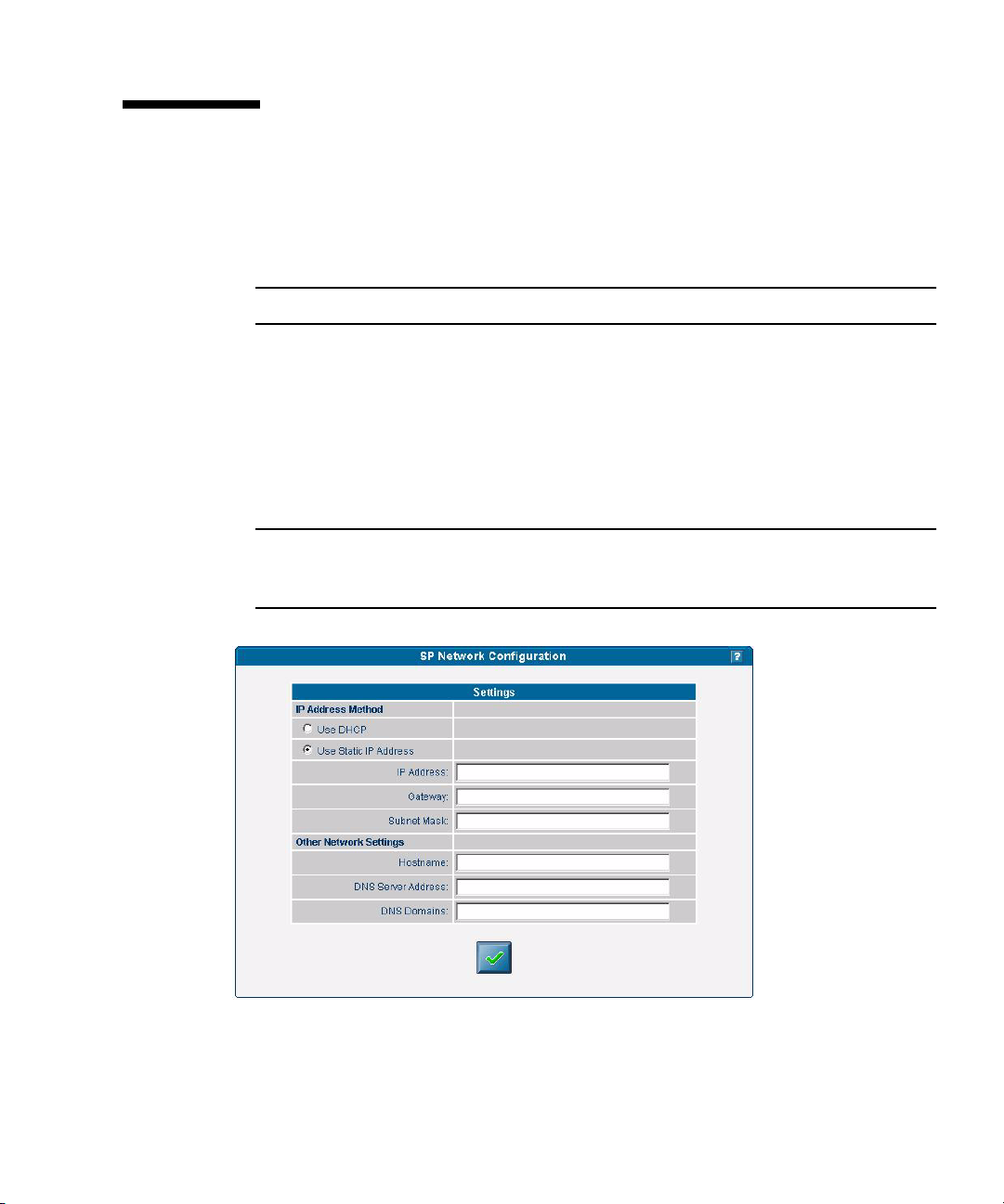
Systems Management Console Features
The server can be managed using line commands or by using the Web-based
Systems Management (SM) Console graphical interface. This section gives an
overview of the actions you can do with the SM Console interface.
Note – For full information on the line commands, see the appendixes in this guide.
Configuring Network Settings
Administrator and manager-level users can use the SM Console to configure the SP
network settings to define the IP address method (static or DHCP), and other
network settings such as the hostname, DNS server address, and domains.
Note – As discussed in the previous section, you also can configure network
settings from the operator panel, or you can use the sp ip commands, which are
explained in the online help.
FIGURE 1-11 Network Configuration
Chapter 1 Introduction 45

To configure the SP network settings from the SM Console:
1. Click Configuration>SP Network from the menu bar.
2. In the Settings table, choose the radio button for the IP Address Method (DHCP
or Static IP Address) that you want to use.
3. If you chose Static IP Address, type the IP address, gateway address, and subnet
mask.
4. Identify other network settings.
■ The host name of the SP
■ A single IP address of a DNS server (if available)
■ A space-separated list of search domains (if applicable)
5. Click the check-mark button to save the settings.
Note – If you choose DHCP, the SP broadcasts for a DHCP server to obtain a
dynamic IP. The IP address information displays, but you cannot edit it.
Starting and Stopping the Platform OS
Administrator and manager-level users can start and stop the platform operating
system from the SM Console. Choose Management>Platform Operations from the
menu bar, then choose one of the options listed in the table below.
TABLE 1-7 Stop and Start Options
Option Description
Power On /
Restart
46 Sun Fire V20z and Sun Fire V40z Servers—Server Management Guide • July 2005
The Power On/Restart option starts the platform operating system.
The Boot into BIOS Setup option boots the platform and causes BIOS to
enter setup mode. This allows you to modify the BIOS settings from
the platform console. After you select this option, you must access the
BIOS configuration screen to change BIOS settings. See the User Guide
for your server for details about configuration of BIOS settings.
For remote access, log in via the SM Console. Choose
Troubleshooting>SP SSH Console. Then execute the platform
console command.
The Forced Restart option bypasses the operating system shutdown
stage during a system restart. It can cause loss of data.

TABLE 1-7 Stop and Start Options (Continued)
Option Description
Shutdown /
Power Off
The Shutdown/Power Off option shuts down the platform operating
system and powers off the machine.
The Forced Power Off option bypasses the operating system shutdown
stage. It might cause loss of data. Use the Forced Power Off option if
you must force a shutdown.
After you choose an option and click the check-mark button, the operation is
initiated on the server. The help text displays any processing and results messages.
The current state is reflected in the System Status button, so you can monitor the
progress.
When you “mouse over” the Platform Operating System button, one of these states
displays in the help panel:
■ Off
■ On
■ Communicating
■ Diagnostics
■ Sleeping
■ BIOS booting
■ BIOS setup
■ OS booting
■ OS shutting down
Note – You can perform platform state management from the command line with the
platform sub-commands. See Appendix F of this guide for more information.
If the power currently is off, the Shutdown/Power Off option returns a message that
the option was not executed, due to the current state.
Configuring SMTP Event Notification
Administrator and manager-level users can configure the system to:
■ Send e-mail for generated events, via a Simple Mail Transfer Protocol (SMTP)
server.
■ Route e-mail based on the severity of events.
■ Send e-mail that contains a subject and content (long format), or only a subject
(short format) to support target devices such as phones, pagers, and so on.
Chapter 1 Introduction 47
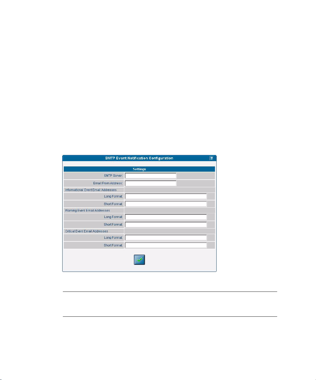
SMTP notification ensures rapid notification about events and rapid response to
critical situations. You can use the SM Console or the sp smtp commands to
configure SMTP event notification.
Follow these steps to configure automatic SMTP email alerts from the SM Console:
1. Click Configuration>SMTP Event Notification from the menu bar.
2. Type the SMTP server name (either the host name or IP address of the SMTP
server where you want email to be routed.) Use an IP address unless DNS is
configured on the SP.
3. For each level of severity, type a comma-separated list of email addresses. These
are the addresses that will receive email for each level of severity. Severity levels
are:
■ informational
■ warning
■ critical
FIGURE 1-12 SMTP Event Notification
Note – Type separate address lists for short and for long e-mail formats. Type a
comma between each e-mail address. Type a separate list for pager e-mail addresses
that require shorter text.
4. Click the check-mark button to save the settings.
48 Sun Fire V20z and Sun Fire V40z Servers—Server Management Guide • July 2005

Configuring Directory Services
Configure the directory services options to define how SP username and password
information is stored or accessed.
TABLE 1-8 Directory Services Options
Option Description
NIS Network Information Service: A UNIX-originated solution to directory
service. Both local files and a remote NIS server authenticate users.
ADS Active Directory Service: Microsoft’s directory service. Both local files and a
remote ADS server authenticate users.
You can use the SM Console or the access subcommands to configure the
directory services options. See Appendix B of this guide for more information.
To configure directory services from the SM Console:
1. Click Access Control>Directory Services from the menu bar.
2. If you want to use local authentication only, select the first radio button in the
Settings table.
or
If you want to use directory services, select the radio button for the network
directory services database you want to use.
Chapter 1 Introduction 49

FIGURE 1-13 Directory Services Configuration
3. Type the domain name for the option you selected in Step 2.
4. Type the server name for the option you selected in Step 2. (For multiple servers,
type a comma between each server name.)
5. If you chose ADS, also type the organizational unit, ADS Logon ID, and the
location of the keytab file. (See
6. Click the check-mark button to save the settings.
“Creating Keytab Files for ADS” on page 52.)
Note – If you use ADS, the clock on the Service Processor must synchronized with the clock
on the ADS server. Also, the Service Processor and the ADS server must be able to resolve
each other’s hostnames using DNS.
Remote users who are authenticated via directory services have access to the SP only via a group
mapping that maps the user’s remote group to a SP administrative group.
To simplify configuration on the SP, manager-level users can map directory service groups to
predefined groups. When you map those users (members of directory services groups) to a SP
administrative group, they automatically have appropriate access rights.
50 Sun Fire V20z and Sun Fire V40z Servers—Server Management Guide • July 2005

Mapping Directory Service Groups
The Directory Service Group Mappings table identifies existing group mappings.
This table also provides options for mapping other directory service groups to an SP
group. For example, if Directory Services group 5 is mapped to manager, all
members of group 5 are granted manager-level privileges on the SP.
To map directory service groups from the SM Console:
1. Click Access Control>DS Group Mappings from the menu bar.
The current group mappings table displays. Directory services groups are listed
alphabetically.
FIGURE 1-14 Directory Services Group Mappings
2. Choose one of the following:
■ Select the radio button for the mapping you want to create (monitor, admin,
manager).
■ Select No Mapping to disable access to the SP.
■ Enter a new group in the text field and select one of the corresponding radio
button options to indicate the SP group for the new entry.
■ Select the Verify checkbox so that an error will display if a new group name is not
located in the directory service.
3. Click the check-mark button.
Chapter 1 Introduction 51

Creating Keytab Files for ADS
To use ADS as a directory service on the SP, you must create an active directory
account. The name service library on the SP uses this account to authenticate itself to
the LDAP interface of the active directory server.
ADS Server Requirements
■ The ADS server must have Certificate Services and the High Encryption Pack
installed.
■ The Windows administrator must create an Active Directory account and a keytab
(for that account) that the SP(s) will use to conduct LDAP queries. You can create
keytab files with the ktpass command that is located in the Microsoft Windows
2000 resource kit:
ktpass -princ <logon>@<domain> -pass <password> -mapuser <logon> -out
<output filename>
Note – The keytab you create with this command can be uploaded to the SP with the scp
command, or can be accessed from an exported file system that is mounted by the SP.
See your Microsoft documentation for details about this command.
ADS SP Requirements
■ You must configure DNS.
■ The canonical name of each host must be the fully-qualified host name
(including the domain).
■ The IP address of each host must reverse-resolve to the canonical name.
■ The time on the SP must be accurate to within five minutes of the time on the
ADS server (domain controller). When the platform is started, the SP clock syncs
with the platform clock.
■ You must configure ADS properly. From the SM Console, type:
■ The ADS domain.
■ The ADS server name.
■ The organization unit (OU) under which the SP searches for group
information.
■ The ADS logon ID (the name of the account that was created for the SP to use).
■ The keytab file that was uploaded and installed on the SP.
52 Sun Fire V20z and Sun Fire V40z Servers—Server Management Guide • July 2005

Configuring Date and Time
Administrator and manager-level users can configure the date and time setting for
the SP clock. Use the sp date command from the command line or configure date
and time from the SM Console.
■ The clock is synchronized automatically when platform drivers are installed. If
the platform is running (and the drivers are installed) the platform time takes
precedence over the SP time.
■ The platform time must be set correctly for ADS to function.
If you configure the SP before you load the platform operating system and you want
to set the time to synchronize with ADS and other network services, follow the
procedure below.
From the SM Console:
1. Click Configuration>SP Date/Time from the menu bar.
2. Identify the date and time on the SP clock.
The current SP time displays in yyyy:mm:dd hh:mm:ss format. Figure 1-15
illustrates an example of this format.
FIGURE 1-15 Date/Time Configuration
3. Click the check-mark button to save the settings.
Chapter 1 Introduction 53

Configuring SSL
Set up Web access to the SP with either an encrypted or a non-encrypted
communication method.
By default, all messages between your browser and the SP are encrypted according
to Hypertext Transfer Protocol over Secure Socket Layer (HTTPS). Version 0.9.6j is
supported.
1. Allow browsers to communicate with the SP via non-encrypted messages by one
of the following two methods:
■ From the command line, use this command:
sp disable ssl-required
■ From the SM Console, select the Optional (disable) or Required (enable) radio
buttons from the SSL Certificate configuration page as described in
the SSL Certificate from the SM Console” on page 54.
With SSL disabled, HTTP requests are serviced directly without any redirection to
HTTPS. HTTPS requests continue to be secure.
Note – If you enable the HTTPS protocol, your browser will display a warning
message that states that it cannot verify the validity of the Server Certificate. This
warning is informational and you can ignore it safely. The warning displays because
the Server Certificate that is shipped with the SP is self-signed by Newisys, Inc. To
upload a certificate that is signed by your own organization or by an independent
certificate authority, select User Supplied, as described in
Certificate from the SM Console” on page 54.
“Configuring the SSL
“Configuring
2. To revert to the default behavior, use the command:
sp enable ssl-required
With SSL enabled, HTTP requests are redirected automatically to equivalent HTTPS
requests to maintain site security.
Configuring the SSL Certificate from the SM Console
Administrator and manager-level users can enable or disable SSL encryption and
can define the SSL certificate that is used to manage transmission security.
Note – You also can use sp ssl commands to configure the SSL certificate. See
Appendix H of this document or the SM Console online help for details about
commands.
54 Sun Fire V20z and Sun Fire V40z Servers—Server Management Guide • July 2005

Follow these steps to configure the SSL certificate from the SM Console:
1. Click Configuration>SSL Certificate from the menu bar.
2. Select the radio button to designate SSL access as required or optional.
FIGURE 1-16 SSL Configuration
3. Do one of the following, depending on whether you selected required or optional:
■ If you selected Required, select the radio button for the type of SSL certificate
configuration you want to use, factory-installed or your own in-house certificate
management.
■ If you selected User-supplied:
a. Enter the name of your generated certificate file to be installed with Apache on
the SP, or click the Browse button to search for a file.
b. Enter the name of your generated key file to be installed with Apache on the
SP, or click the Browse button to search for a file.
4. Click the check-mark button.
Chapter 1 Introduction 55
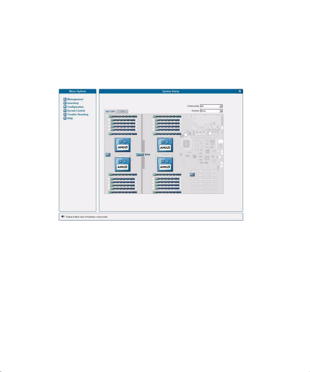
Monitoring System Status
The System Status window displays an image that represents the physical layout
and status of all hardware components and sensors. You can use this window to
identify components that have problems, or failed components that must be
replaced. To access this window, click the System Status button from the toolbar in
the SM Console
FIGURE 1-17 System Status, Bottom Tab, Sun Fire V40z Server
The component images represent the actual physical hardware components
including their approximate location, size, and status. The hardware layout for the
Sun Fire V40z server is represented in two layers. (Figure 1-17 illustrates the default,
bottom tab view for the dual-core Sun Fire V40z server.) Click the Bottom and Top
tabs at the top of the image to change views.
56 Sun Fire V20z and Sun Fire V40z Servers—Server Management Guide • July 2005
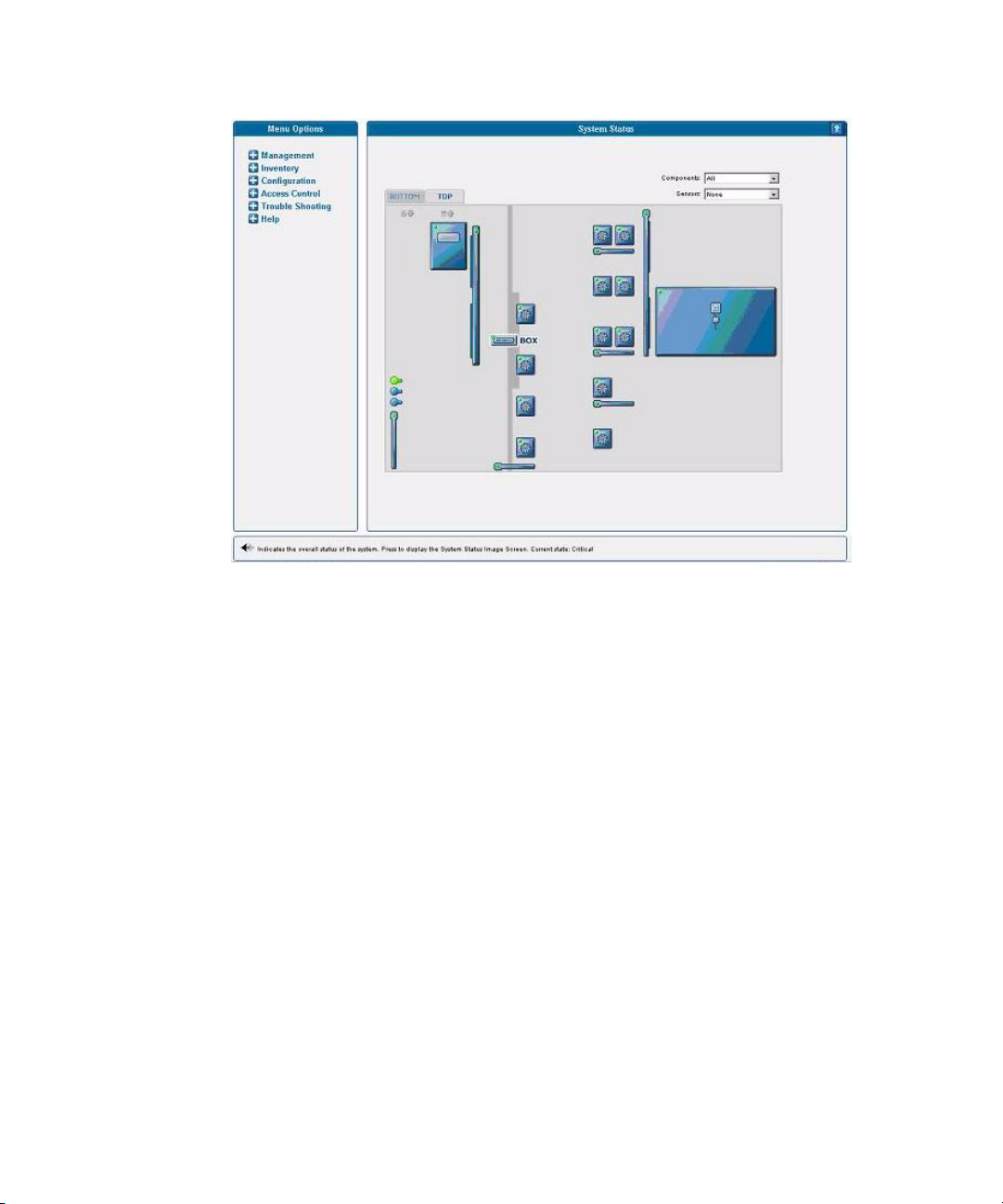
FIGURE 1-18 System Status, Top Tab, Sun Fire V40z Server
You also can display component details for troubleshooting purposes. To view
details about a component, click on the image of that component. You also can use
the pulldown menus in the top right corner of the image to locate specific
component types (CD-ROM drives, CPUs, disk drives, fans, and so on) and specific
sensor types (fan, power, and temperature sensors).
Sensor images represent the approximate location, current value, and warning or
critical thresholds of system sensors. Current information about the sensor (name,
type, current value, low and high warning, critical thresholds, and status) displays
in a gauge component in the top right corner of the image.
Chapter 1 Introduction 57
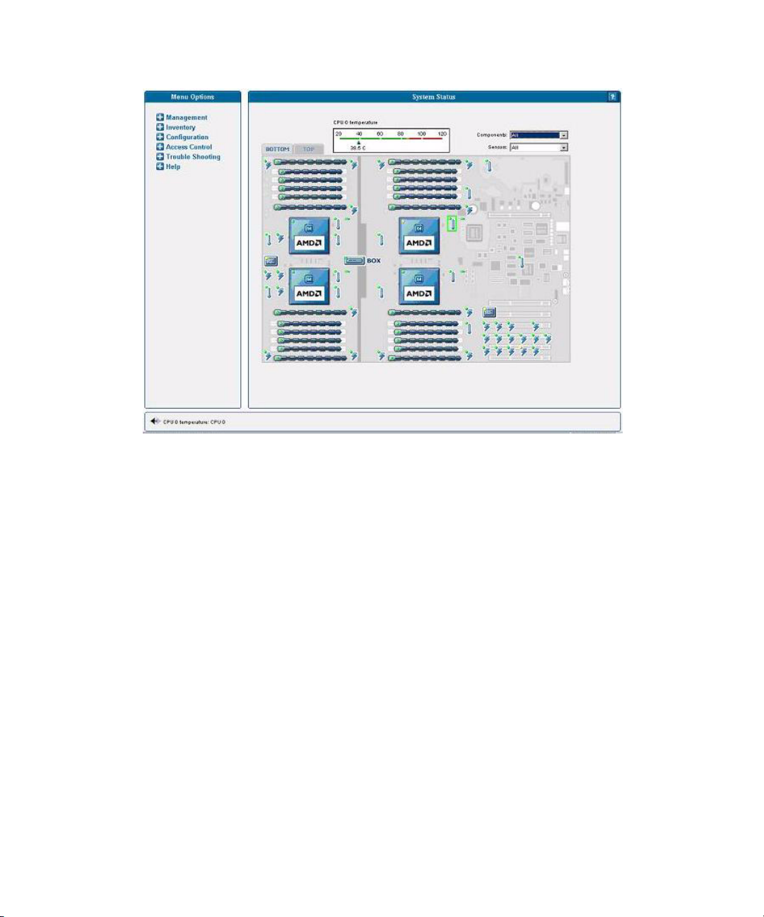
FIGURE 1-19 Temperature Sensors Displayed in Bottom Layer
To view values for a sensor, click on the image of the sensor. In Figure 1-19, which
illustrates the bottom layer, the temperature sensor gauge for CPU0 displays.
58 Sun Fire V20z and Sun Fire V40z Servers—Server Management Guide • July 2005
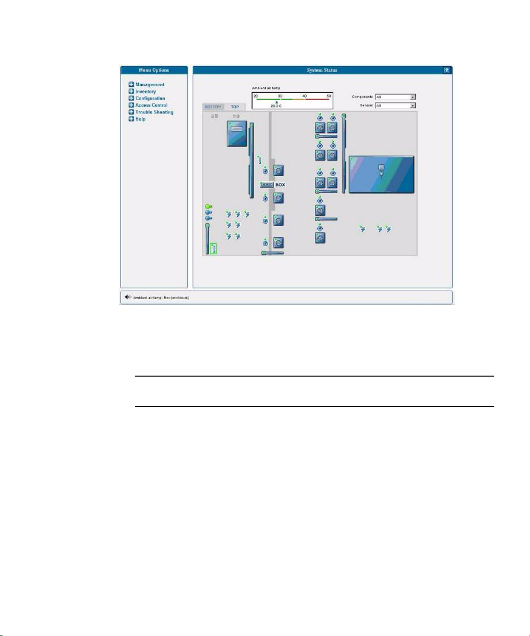
FIGURE 1-20 Ambient Air Temperature Gauge Displayed, Top Layer
In Figure 1-20, which illustrates the top layer, the sensor gauge for the ambient air
temperature displays.
Note – See the SM Console online help for additional instructions and details about
management tasks.
System Events
Administrators with appropriate privileges can use the SM Console’s System Events
table to view detailed information about all active events. They also can perform
various actions that are related to each event.
Each active event displays on its own row in the table, as illustrated in Figure 1-21,
below.
Chapter 1 Introduction 59
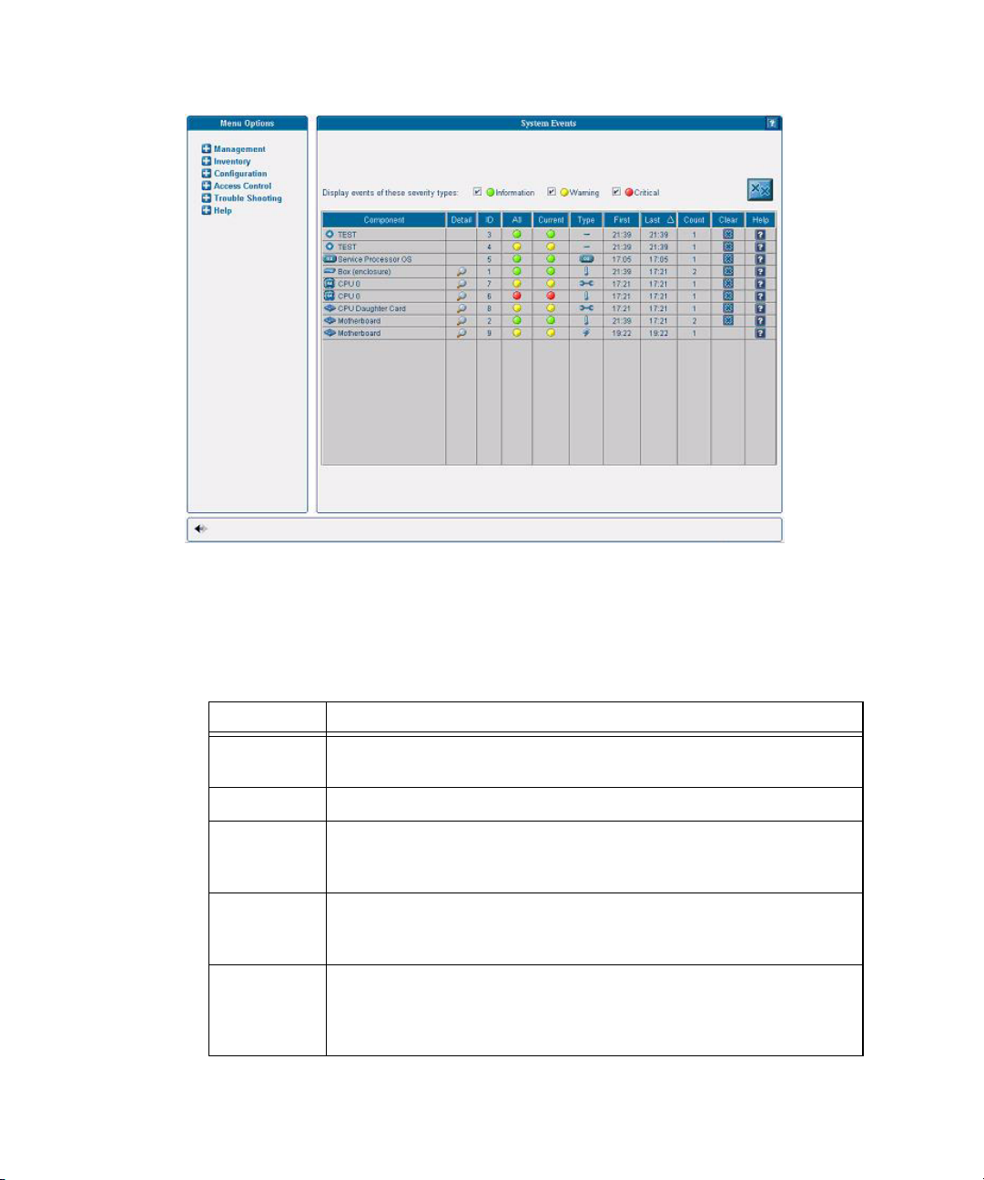
FIGURE 1-21 System Events Table
Table 1-9 describes the columns in the System Events table.
TABLE 1-9 System Events Table
Column Description
Component The unique name of the component that has caused this event.
Components can be hardware or software.
Detail Displays details for the component.
ID Contains a unique event ID for each event allowing you to track the
event in your external trouble-ticket system and query the log files for all
actions related to the event.
All Displays the highest severity that this event has ever achieved:
informational (green), warning (yellow), critical (red) icons. Click the
icon to view details for the event.
Recent Displays the current severity (informational (green), warning (yellow),
critical (red) icons) and a descriptive message. These descriptions might
be lengthy, (for example, describing the nominal, warning, critical, and
current temperature for a fan) and therefore display in the help panel.
60 Sun Fire V20z and Sun Fire V40z Servers—Server Management Guide • July 2005

TABLE 1-9 System Events Table (Continued)
Column Description
Type Identifies the event type. Refer to TABLE 1-10 for a description of the
icons representing each type.
First Lists the date and time at which the event was initially generated. Only
the time displays in the table; help text at the bottom of the window
displays the entire date and time.
Last The date and time at which the event was most recently generated. Only
the time displays in the table; help text at the bottom of the window
displays the entire date and time.
Count Lists the number of times the event has occurred. If a new event has the
same component and event type as a current, uncleared event, a new
event is not created but the count for the current event is incremented
and the current severity is updated in the recent column.
Clear Clicking this button clears the event. You must manually clear all events.
A cleared event is deleted from the server and automatically cleared
from any other connected SM Console System Events screen. Only
administrator and manager-level users can clear events.
Note – You also can use the sp get events command to obtain information about
events. See Appendix H of this document or the online help for more information
about this command.
Chapter 1 Introduction 61
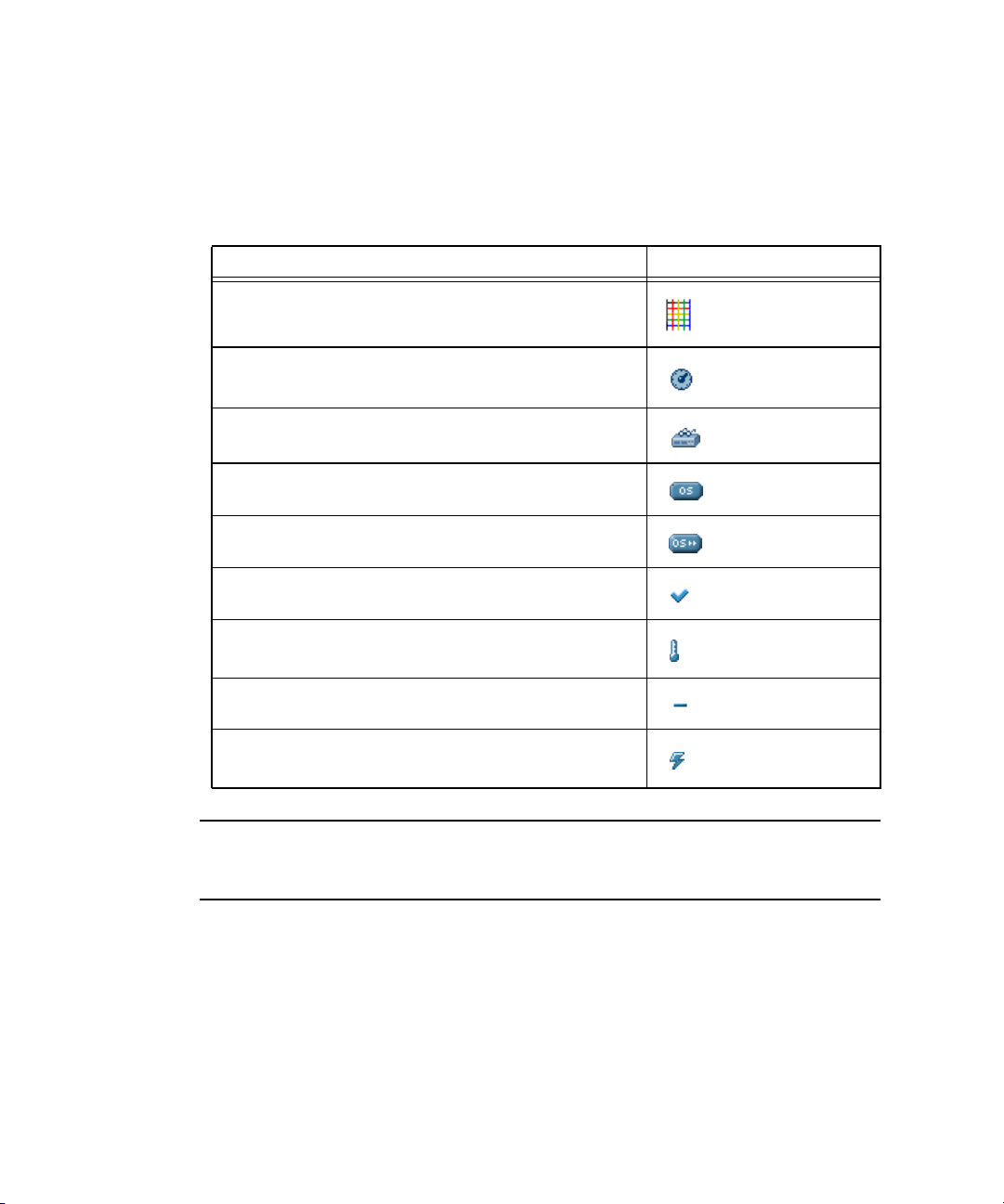
Event Type Icons
The SM Console displays the icons that are illustrated in Table 1-10 to represent
specific types of events.
TABLE 1-10 System Event Type Icons
Event Type Icon
BIOS Events
Fan Speed Events
Machine Check Events
Miscellaneous Operating System Events
Platform State Events
Switch Events
Temperature Events
Unknown Event
Voltage Events
Note – See the Sun Fire V20z and Sun Fire V40z Servers Troubleshooting Techniques and
Diagnostics Guide 817-7184 for a table of system events and troubleshooting
suggestions.
62 Sun Fire V20z and Sun Fire V40z Servers—Server Management Guide • July 2005

CHAPTER
2
IPMI Server Management
Server manufacturers today have to re-invent how each new server manages itself.
The hardware and software design for one server does not necessarily work with
another. Every server supplier provides basic monitoring and data collection
functions but no two do it exactly the same. These proprietary implementations for
manageability only complicate the problem.
Intelligent Platform Management Interface
The standardization of server-based management, called Intelligent Platform
Management Interface (IPMI), provides a solution. IPMI allows you to interconnect
the CPU and devices being managed. It allows for:
■ Easy replication of the monitoring functions from server to server
■ Support for a reasonably large number of monitoring devices
■ Common driver-level access to management instrumentation
■ More cost-effective implementations
■ Increased scalability of the server management functions
IPMI is an industry-standard, hardware-manageability interface specification that
provides an architecture defining how unique devices can all communicate with the
CPU in a standard way. It facilitates platform-side server management and remote
server-management frameworks, by providing a standard set of interfaces for
monitoring and managing servers.
With IPMI, the software becomes less dependent on hardware because the
management intelligence resides in the IPMI firmware layer, thereby creating a more
intelligently managed server. The IPMI solution increases server scalability by
distributing the management intelligence closer to the devices that are being
managed.
63

Baseboard Management Controller
In order to perform autonomous platform-management functions, the processor
runs embedded software or firmware. Together, the processor and its controlling
firmware are referred to as the Baseboard Management Controller (BMC), which is
the core of the IPMI structure. Tightly integrating an IPMI BMC and management
software with platform firmware provides a total management solution.
Note – Another way to perform IPMI queries and actions on the BMC is through
the IPMI client utility ipmitool, which
For more information, see “Lights Out Management (LOM)” on page 74.
The BMC is a service processor integrated into the motherboard design, providing a
management solution independent of the main processor. The monitored server can
communicate with the BMC through one of three defined interfaces, which are based
on a set of registers shared between the platform and the BMC.
Note – In these servers, the SP has software that emulates a BMC.
The BMC is responsible for:
■ Managing the interface between server management software and platform
management hardware
■ Interfacing to the system sensors, such as fan speed and voltage monitors
■ Providing access to the system event log
■ Providing autonomous monitoring, event logging and recovery control
■ Acting as a gateway between the management software and the IPMB/ICMB
■ Monitoring the system watchdog timer
■ Facilitating the remote-management tasks, even when the main server hardware
is in an inoperable state
is used extensively in the testing process.
The BMC provides the intelligence behind IPMI. In these servers, the SP serves as
the BMC, providing access to sensor data and events through the standard IPMI
interfaces.
64 Sun Fire V20z and Sun Fire V40z Servers—Server Management Guide • July 2005

Manageability
IPMI defines a mechanism for server monitoring and recovery implemented directly
in hardware and firmware. IPMI functions are available independent of the main
processors, BIOS and operating system.
IPMI monitoring, logging and access functions add a built-in level of manageability
to the platform hardware. IPMI can be used in conjunction with server-management
software running under the OS, which provides an enhanced level of manageability.
IPMI provides the foundation for smarter management of servers by providing a
methodology for maintaining and improving the reliability, availability and
serviceability of expensive server hardware.
Functional Overview
The following list details the main features of IPMI in the servers:
■ A fully functional Sensor Data Record Repository (SDRR) is the container for and
interface from which you can access sensor data records (SDRs).
The BMC owns all sensors within the repository. The SDRR features include:
■ a single management controller record
■ threshold-based analog sensors for temperature, voltage, fans and power
■ device locator records for FRUs, to which the physical sensor records are
linked (through entity ID/instance relationships)
■ various discrete sensors and event-only sensors
■ The System Event Log (SEL) is a 16K maximum persistent file. For more
information, refer to
■ The watchdog timer (WDT) supports all timer uses, no pre-timeout interrupt
actions, and all (reset, power down, power cycle) timeout actions. For more
information, refer to
■ A Field-Replaceable Unit (FRU) is read-only. It is tightly integrated with the SP’s
inventory-management functionality. For more information on the inventory
commands, see Appendix
inventory command is also available from the FRU.
■ The following chassis-control actions are available:
■ Power down
■ Power up
■ Power cycle
■ Hard reset
■ Soft shutdown
■ Event filtering and unacknowledged Platform Event Trap (PET) alerts are
supported. For more information, refer to
“System Event Log” on page 68.
“Watchdog Timers” on page 73.
D in this guide. VPD data that is available through the
“Event Filters” on page 72.
Chapter 2 IPMI Server Management 65

■ Both SMS and LAN channels are supported. Refer to “IPMI Compliance and LAN
Channel Access” on page 66.
■ Serial Over LAN (SOL) provides serial-port redirection over the LAN channel.
Refer to
“Serial Over LAN” on page 117.
IPMI Compliance and LAN Channel Access
The server supports IPMI with both SMS and LAN channels through the SP software
version 2.2 and later. These servers meet compliance standards for IPMI version
The SMS is implemented as a Keyboard Controller Style (KCS) interface.
The IPMI implementation on these servers also support LAN channel access. (Refer
to the IPMI specification v2 for details.) By default, the LAN channel access is
disabled. To enable it, use the ipmi enable channel command and specify the ID
of the channel to enable for the LAN Interface, as follows.
Note – This ID is case-sensitive and must be lowercase.
# ssh spipaddr -l spuser ipmi enable channel {sms | lan}
As part of this command, you also specify the password for the default null user.
The null user can then use IPMI over the LAN interface. For more information, see
“Usernames and Passwords” on page 67.
2.
For more information about enabling or disabling the IPMI channel, refer to
Appendix E.
66 Sun Fire V20z and Sun Fire V40z Servers—Server Management Guide • July 2005

Usernames and Passwords
Operator and administrator-level access over the LAN channel requires a valid
user
ID and password. These servers are not pre-configured with user accounts
enabled. When you initially enable the LAN channel through the command
ipmi
enable channel, you are required to provide the password for the null
user. See
“IPMI Compliance and LAN Channel Access” on page 66.
Note – For security reasons, the LAN channel access is disabled by default.
Note – IPMI user identities are in no way associated with user accounts defined for
server-management capabilities. Refer to
“Initial Setup of the SP” on page 14 for
more information about these server-management user accounts.
Server Boot-Option Support
IPMI allows you to set a number of boot options for interpretation by BIOS. TABLE 2-1
describes important information about the server boot options and parameters that
the BIOS supports.
TABLE 2-1 Boot Options
Parameter Number Details
Set In Progress 0 This parameter is fully supported except for the
rollback functionality
BMC boot flag valid
bit clearing
Boot info ack 4 BIOS supports indicating that it has handled
Boot Flags 5 • Data byte 1 is supported for the boot flags
3 Fully supported.
boot information.
valid bit.
• Data byte 2 (CMOS Clear) is supported;
however, when this bit is set, all other bits in
this byte are ignored.
• Lock keyboard is fully supported.
• Boot device selector is supported except for
booting to BIOS Setup.
• Data byte 3 is supported for user
password bypass
Chapter 2 IPMI Server Management 67

System Event Log
The IPMI System Event Log (SEL) is part of the BMC. Several types of information
are logged to the SEL, from administrative messages to indications of important
events, such as sensor-threshold crossings.
The size of the log is 16MB, which allows for 1024 records.
Sensors
Sensors generate events, obtain readings and set thresholds. The Sensor Data Record
Repository (SDRR) contains several types of sensors.
You access all sensors through the BMC. Many sensors represent physical sensors
that are distributed on the motherboard and contained within FRUs. These sensors
are polled. When they cross a threshold, an entry is entered in the SEL.
For more information on sensor commands, see Appendix G
Determine Sensor Presence
To determine the presence of a sensor, run the subcommand sensor get.
A sensor that is offline (not reporting) or physically not present in the system is
indicated by state unavailable in the command response data.
Sensor Thresholds
To retrieve sensor thresholds, run the subcommand sensor get.
To set sensor thresholds, run subcommand sensor set.
If you specify no thresholds, the result is no change and the return code is success.
68 Sun Fire V20z and Sun Fire V40z Servers—Server Management Guide • July 2005

TABLE 2-2 lists the completion codes that are returned by the subcommand
set sensor.
TABLE 2-2 Completion Codes
Code Cause
0x00 (success) Sensor thresholds set as requested.
0xCD (illegal command) Sensor thresholds are unchangeable.
0xCC (invalid request) Attempting to set an unsettable threshold or attempting to
set thresholds in an improper order (for example, the upper
critical threshold is set lower than the upper non-critical
threshold).
0xC0 (node busy) Processing resources are temporarily unavailable.
Temperature Sensors
Temperature sensor readings are defined within a range of 0˚C to 150˚C, a difference
of 151˚C. The CPU die temperature thermal trip occurs at approximately 140˚C.
Temperature sensors can generate the following SEL events:
■ Upper Critical Moving Higher Assertion
■ Upper Critical Moving Higher De-assertion
■ Upper Non-critical Moving Higher Assertion
■ Upper Non-critical Moving Higher De-assertion
Memory Sensors for DIMMs
Each DIMM has its own record, which is used only to log IPMI events.
For more information, refer to the section “Analyzing Events” in the Sun Fire V20z
and Sun Fire V40z Servers—Troubleshooting Techniques and Diagnostics Guide (817-7184).
Voltage Sensors
All voltage sensor readings are indicated in volts (V). The largest voltage swing that
is measured is 15V (the bulk voltage sensor ranges from 0V to 15V). Many of the
voltage sensors have much lower maximums and smaller ranges. Voltage sensors
can generate the following SEL events:
■ Upper Critical Moving Higher Assertion
■ Upper Critical Moving Higher De-assertion
■ Lower Critical Moving Lower Assertion
Chapter 2 IPMI Server Management 69

■ Lower Critical Moving Lower De-assertion
Fan Sensors
The values reported for all fan-speed sensor readings are indicated in revolutions
per minute (RPMs). The sensors have an upper bound of 15
000 RPM.
Fan sensors can generate the following SEL events:
■ Lower Critical Moving Lower Assertion
■ Lower Critical Moving Lower De-assertion
Power-Supply Sensors
All power sensor readings are indicated in watts (W) and are defined within a range
of
0W to 600W.
■ Power sensors do not generate SEL events.
■ There are no thresholds for power sensors.
Management Controllers
One management-controller sensor represents the BMC. The management controller
has the following capabilities:
■ Global Initialization. The init agent enables the controller to generate
messages.
■ Device Capabilities. This device acts as all of the following:
■ Chassis Device
■ IPMB Event Receiver
■ FRU Inventory Device
■ SEL Device
■ SDR Repository Device
■ Sensor Device
Miscellaneous Sensors
The following additional sensors also are supported:
■ System Event
■ Event Logging Disabled
■ System Firmware Progress
■ Watchdog
70 Sun Fire V20z and Sun Fire V40z Servers—Server Management Guide • July 2005

System Event
The system-event sensor indicates a variety of system events. However, no event
conditions are reflected from the subcommand sensor get.
PEF actions. Pending actions against a filter that has been matched are logged if the
event sensor has been configured to do so. Only assertions of pending PEF action
conditions are logged.
Sensor Type Code: 0x12 [System Event]
Sensor Specific Offset: 0x04 [PEF Action]
Time sync. Time-sync events occur in pairs: one before and one after a SEL time
sync.
Sensor Type Code: 0x12 [System Event]
Sensor Specific Offset: 0x05 [Time sync]
Event Logging Disabled
The sensor event logging disabled indicates certain SEL-related events. This
sensor is represented as a ‘type 2’ SDR record.
SEL Full. When the SEL reaches the “maximum-1” number of records, a record is
logged and any subsequent add SEL commands return a limit-exceeded code. This
record becomes the last record in the SEL when it is filled to capacity.
Sensor Type Code: 0x10
Sensor Specific Offset: 0x04 [Log Full]
SEL Clear. A record is written to the SEL whenever the command Clear SEL is
executed. This occurs only on the command Clear SEL; it does not occur if you
delete the last SEL entry with the command Delete SEL Entry.
Sensor Type Code: 0x10
Sensor Specific Offset: 0x02 [Log AreaReset/Cleared]
Chapter 2 IPMI Server Management 71

System Firmware Progress
The system-firmware progress sensor is an event-only sensor. The BIOS Boot Success
SEL entry can be logged against this sensor when the BIOS has successfully booted
and has attempted to return control to the OS, or if the BIOS has been booted and
you enter a BIOS Setup screen.
Sensor Type Code: 0x0F
Sensor Specific Offset: 0x02 [Firmware Progress]
Event Data 2: 0x13 [Starting operating system boot process]
Watchdog
The Watchdog 2 sensor is used to log watchdog timer expirations. These events
are generated only for timers that do not have the “do not log” bit set. A
timer-expiration event is logged when a watchdog timer expires.
Sensor Type Code: 0x23
Sensor Specific Offset: * all supported actions
Event Filters
Note – To ensure a graceful shutdown, the correct platform drivers must be
installed on the server.
Platform Event Filtering (PEF) provides policy management that enables the BMC to
act on particular events. The supported actions through PEF include:
■ Power down
■ Power cycle
■ Reset
■ Send Alert
TABLE 2-3 lists the event filters are enabled by default.
TABLE 2-3 Event Filters Enabled By Default
Filter Match Action
ambienttemp asserts upper critical threshold Power down
cpu0.dietemp asserts upper critical threshold Graceful power down
72 Sun Fire V20z and Sun Fire V40z Servers—Server Management Guide • July 2005

TABLE 2-3 Event Filters Enabled By Default
Filter Match Action
cpu1.dietemp asserts upper critical threshold Graceful power down
cpu2.dietemp asserts upper critical threshold
Note: This filter is ignored on systems with two CPUs.
cpu3.dietemp asserts upper critical threshold
Note: This filter is ignored on systems with two CPUs.
Graceful power down
Graceful power down
Watchdog Timers
A watchdog timer allows a selected action to occur when the timer expires.
For timer actions, pre-timeout interrupts are currently not supported. The following
actions are supported:
■ System Reset
■ System Power Off
■ System Power Cycle
Alerting
When you use Platform-Event-Trap (PET) LAN alerts, the number of alert
destinations is limited to 16 (one non-volatile, fifteen volatile). The number of alert
policies is limited to 32.
Note – Acknowledgement of PET LAN alerts and alert strings are unsupported.
Alert Policy Set Determination
When event filters are matched, the following occurs:
■ all non-alert actions are scanned for the filters
■ the highest priority action associated with all filters is taken
■ all alert actions are scanned for the filters
■ the highest priority (based on lowest numeric policy number) alert policy set is
chosen
You can configure policies so that, if the previous alert was successful, an alert is not
sent as a result of the execution of the alert policy.
Chapter 2 IPMI Server Management 73

Lights Out Management (LOM)
On these servers, Lights Out Management is performed through IPMItool, a utility
for controlling IPMI-enabled devices.
Description
IPMItool is a simple command-line interface (CLI) to servers that support the
Intelligent Platform Management Interface (IPMI) v1.5 specification. It provides the
ability to:
■ Read the Sensor Data Record (SDR) and print sensor values
■ Display the contents of the System Event Log (SEL)
■ Print information about Field Replaceable Units (FRUs)
■ Read and set LAN configuration parameters
■ Perform chassis power control
Originally written to take advantage of IPMI-over-LAN interfaces, IPMItool is also
capable of using a system interface, as provided by a kernel device driver such as
OpenIPMI.
Further Information
■ For up-to-date information about IPMItool, visit:
http://ipmitool.sourceforge.net/
■ For more information about the IPMI specification, visit:
http://www.intel.com/design/servers/ipmi/spec.htm
■ For more information about the OpenIPMI project (MontaVista IPMI kernel
driver), visit:
http://openipmi.sourceforge.net/
Syntax
The syntax used by IPMItool is as follows:
ipmitool [-ghcvV] -I lan -H address [-P password] expression
ipmitool [-ghcvV] -I open expression
74 Sun Fire V20z and Sun Fire V40z Servers—Server Management Guide • July 2005

Options
TABLE 2-4 lists the options available for IPMItool.
TABLE 2-4 Options for IPMItool
Option Description
-h Provides help on basic usage from the command line.
-c Makes the output suitable for parsing, where possible, by separating fields
with commas instead of spaces.
-g Attempts to make IPMI-over-LAN communications more robust.
-V Displays the version information.
-v Increases the amount of text output. This option may be specified more
than once to increase the level of debug output. If given three times, you
receive hexdumps of all incoming and outgoing packets.
-I interface Selects the IPMI interface to use. The possible interfaces are LAN or open
interface.
-H address Displays the address of the remote server; it can be an IP address or host
name. This option is required for the LAN interface connection.
-P password Displays the password for the remote server; the password is limited to a
maximum of 16
interface; if a password is not provided, the session is not authenticated.
characters. The password is optional for the LAN
Chapter 2 IPMI Server Management 75

Expressions
TABLE 2-5 lists the expressions and parameters available for IPMItool.
Note – For each of these expressions, the beginning command is always ipmitool,
followed by the expression and parameter(s).
Note – The sol command is not supported in these servers, but you can enable a
Serial-over-LAN feature. See “Serial Over LAN” on page 117.
TABLE 2-5 Expressions and Parameters for IPMItool (1 of 4)
Expression Parameter Sub-parameter Description and examples
help Can be used to get command-line help on IPMItool
commands. It may also be placed at the end of commands
to get help on the use of options.
EXAMPLES:
ipmitool -I open help
Commands: chassis, fru, lan, sdr, sel
ipmitool -I open chassis help
Chassis Commands: status, power, identify,
policy, restart_cause
ipmitool -I open chassis power help
Chassis Power Commands: status, on, off, cycle,
reset, diag, soft
raw netfn cmd data Allows you to execute raw IPMI commands (for example,
to query the POH counter with a raw command).
EXAMPLE:
ipmitool -I open raw 0x0 0x1
RAW REQ (netfn=0x0 cmd=0x1 data_len=0)
RAW RSP (3 bytes)
60 00 00
76 Sun Fire V20z and Sun Fire V40z Servers—Server Management Guide • July 2005
 Loading...