

Page 1

Sun Microsystems, Inc.
www.sun.com
Submit comments about this document at: http://www.sun.com/hwdocs/feedback
Sun Fire™V125 Server
Installation Guide
Part No. 819-7422-10
September 2006, Revision A
Page 2

Please
Recycle
Copyright 2006Sun Microsystems,Inc., 4150 Network Circle, SantaClara, California95054, U.S.A. All rights reserved.
Sun Microsystems, Inc.has intellectual property rights relating to technologythat isdescribed in this document. Inparticular, and without
limitation, theseintellectual propertyrights may include one ormore ofthe U.S. patents listed athttp://www.sun.com/patentsand one or
more additional patents orpending patent applications in theU.S. and in other countries.
This documentand the product to which it pertainsare distributedunder licenses restricting their use,copying, distribution,and
decompilation. Nopart of the product or of thisdocument may be reproduced in any formby anymeans without priorwritten authorizationof
Sun andits licensors, if any.
Third-party software, including fonttechnology, iscopyrighted andlicensed from Sun suppliers.
Parts ofthe productmay be derived from BerkeleyBSD systems,licensed from the University ofCalifornia. UNIXis a registered trademark in
the U.S.and in other countries, exclusivelylicensed throughX/Open Company,Ltd.
Sun, Sun Microsystems, theSun logo, Sun Fire, Java, OpenBoot, andSolaris aretrademarks or registered trademarks of SunMicrosystems, Inc.
in theU.S. and in other countries.
All SPARCtrademarks areused under license and are trademarksor registeredtrademarks ofSPARCInternational, Inc. in the U.S.and in other
countries. Products bearingSPARCtrademarks arebased upon an architecture developed by SunMicrosystems, Inc.
The OPENLOOK and Sun™ Graphical UserInterface was developed by SunMicrosystems, Inc.for its users and licensees. Sun acknowledges
the pioneeringefforts ofXerox inresearching anddeveloping the concept of visualor graphical user interfaces forthe computer industry.Sun
holds anon-exclusive license from Xeroxto the Xerox GraphicalUser Interface,which license also covers Sun’slicensees who implement OPEN
LOOK GUIsand otherwise comply with Sun’swritten license agreements.
U.S. GovernmentRights—Commercial use.Government users are subject tothe SunMicrosystems, Inc. standard license agreement and
applicable provisions ofthe FAR and its supplements.
DOCUMENTATION IS PROVIDED "AS IS" AND ALL EXPRESS OR IMPLIED CONDITIONS, REPRESENTATIONS AND WARRANTIES,
INCLUDING ANYIMPLIED WARRANTY OFMERCHANTABILITY,FITNESS FOR A PARTICULAR PURPOSE OR NON-INFRINGEMENT,
ARE DISCLAIMED, EXCEPT TO THE EXTENT THAT SUCH DISCLAIMERS ARE HELD TO BE LEGALLY INVALID.
Copyright 2006Sun Microsystems,Inc., 4150 Network Circle, SantaClara, Californie95054, Etats-Unis. Tous droits réservés.
Sun Microsystems, Inc.a les droits de propriété intellectuels relatants àla technologiequi est décrit dans cedocument. En particulier, etsans la
limitation, cesdroits depropriété intellectuelspeuvent inclure un ou plusdes brevetsaméricains énumérés à http://www.sun.com/patents et
un oules brevetsplus supplémentairesou les applicationsde breveten attente dans les Etats-Uniset dansles autres pays.
Ce produit oudocument est protégé par un copyright etdistribué avec des licences quien restreignentl’utilisation, lacopie, la distribution,et la
décompilation. Aucunepartie de ce produit ou document nepeut êtrereproduite sousaucune forme, par quelque moyenque ce soit, sans
l’autorisation préalableet écrite de Sun etde ses bailleurs de licence,s’il yen a.
Le logicieldétenu par des tiers, etqui comprendla technologie relative aux polices de caractères,est protégépar un copyright et licenciépar des
fournisseurs deSun.
Des partiesde ce produit pourrontêtre dérivées des systèmes BerkeleyBSD licenciés par l’Université deCalifornie. UNIXest une marque
déposée auxEtats-Unis et dans d’autres pays et licenciéeexclusivement par X/Open Company, Ltd.
Sun, SunMicrosystems, lelogo Sun, Sun Fire, Java,OpenBoot, etSolaris sont des marques defabrique oudes marques déposées de Sun
Microsystems, Inc. aux Etats-Uniset dans d’autres pays.
Toutes lesmarques SPARCsont utiliséessous licence et sont desmarques defabrique ou desmarques déposéesde SPARCInternational, Inc.
aux Etats-Uniset dans d’autres pays. Les produits portantles marquesSPARCsont basés sur une architecture développée par Sun
Microsystems, Inc.
L’interfaced’utilisation graphiqueOPEN LOOK et Sun™ aété développée par Sun Microsystems,Inc. pourses utilisateurs etlicenciés. Sun
reconnaît les efforts depionniers deXerox pour la recherche et le développementdu conceptdes interfaces d’utilisationvisuelle ougraphique
pour l’industriede l’informatique. Sun détient unelicense non exclusive de Xerox surl’interface d’utilisationgraphique Xerox, cette licence
couvrant égalementles licenciéesde Sunqui mettenten placel’interface d’utilisation graphique OPEN LOOK et qui enoutre se conforment aux
licences écritesde Sun.
LA DOCUMENTATION EST FOURNIE "EN L’ÉTAT" ET TOUTES AUTRES CONDITIONS, DECLARATIONS ET GARANTIES EXPRESSES
OU TACITESSONT FORMELLEMENT EXCLUES, DANS LAMESURE AUTORISEEPARLA LOIAPPLICABLE, Y COMPRIS NOTAMMENT
TOUTE GARANTIE IMPLICITE RELATIVE A LA QUALITE MARCHANDE, A L’APTITUDE A UNE UTILISATION PARTICULIERE OU A
L’ABSENCE DE CONTREFAÇON.
Page 3

iii
Contents
Preface vii
1. Introduction to the Sun Fire V125 Server Installation 1
Previewing the Installation Process 1
Verifying the Contents of the Shipping Kit 2
Using the Sun Advanced Lights Out Manager Software 3
2. Installing the Hardware 5
Rackmounting Kit Contents 5
Compatible Racks 5
Installing the Slide Rails 6
▼ To Disassemble the Slide Rails 6
▼ To Install the Mounting Brackets Onto the Server 7
▼ To Attach the Slide Rail Assemblies to the Rack 8
▼ To Install the Server Into the Slide Rail Assemblies 9
3. Powering On and Configuring the Server 11
Understanding the Status Indicators 11
Powering On the Server 11
▼ To Power On From the Keyboard 12
▼ To Power On Using the On/Standby Button 13
Page 4

iv Sun Fire V125 Server Installation Guide • September 2006
Configuring the Server 13
▼ To Configure With the Server’s Details Registered at a Name Server 14
▼ To Configure Without the Server’s Details Registered at a Name Server
14
▼ To Configure a Standalone Server for the First Time 15
Clearing Your Configuration 16
▼ To Clear the Configuration 16
Accessing the Sun Advanced Lights Out Manager Software 16
▼ To Display the ALOM Prompt 17
▼ To Display the Console Prompt 17
Page 5

v
Figures
FIGURE 2-1 Disassembling the Slide Rail Before Installation 7
FIGURE 2-2 Slide Rail Assembly Mounting to Rack Post 8
FIGURE 2-3 Inserting the Server With Mounting Brackets Into the Slide Rails 9
FIGURE 2-4 Slide Rail Lock 10
Page 6

vi Sun Fire V125 Server Installation Guide • September 2006
Page 7

vii
Preface
This document provides you with a detailed guide for rackmounting and
configuring the Sun Fire™ V125 server.
Before You Read This Document
Before you use the instructions in this document, you must prepare your site for the
installation and read the latest product notes. See these documents before you begin
the installation process:
■ Sun Fire V125 Server Getting Started Guide
■ Sun Fire V125 Server Product Notes
See “Related Documentation” on page x for links to these documents.
To complete the installation, you must visit the Sun™ preinstalled software site for
specific configuration instructions, software updates, and patches.
Page 8

viii Sun Fire V125 Server Installation Guide • September 2006
How This Document Is Organized
Chapter 1 contains a description of the installation process, a list of the contents of
the shipping kit, and an overview on using the Sun Advanced Lights Out Manager
software.
Chapter 2 contains a list of the rackmounting kit, a list of compatible racks, and
instructions for mounting the server into the rack.
Chapter 3 contains an overview of the status indicators and instructions for
powering on the server, connecting a console, and configuring the preinstalled
software.
Using UNIX Commands
This document might not contain information about basic UNIX®commands and
procedures such as shutting down the system, booting the system, and configuring
devices. Refer to the following for this information:
■ Software documentation that you received with your system
■ Solaris™ Operating System documentation, which is at:
http://docs.sun.com
Page 9

Preface ix
Shell Prompts
Typographic Conventions
Shell Prompt
C shell machine-name%
C shell superuser machine-name#
Bourne shell and Korn shell $
Bourne shell and Korn shell superuser #
Typeface
*
* The settings on your browser might differ from these settings.
Meaning Examples
AaBbCc123 The names of commands, files,
and directories; on-screen
computer output
Edit your.login file.
Use ls -a to list all files.
% You have mail.
AaBbCc123 What you type, when contrasted
with on-screen computer output
%
su
Password:
AaBbCc123 Book titles, new words or terms,
words to be emphasized.
Replace command-line variables
with real names or values.
Read Chapter 6 in the User ’s Guide.
These are called class options.
You must be superuser to do this.
To delete a file, type rm filename.
Page 10

x Sun Fire V125 Server Installation Guide • September 2006
Related Documentation
The documents listed as online are available at:
http://www.sun.com/products-n-solutions/hardware/docs/
Application Title Part Number Format Location
Getting Started Sun Fire V125 Server Getting Started Guide 819-7423 PDF and
HTML
Online
Administration Sun Fire V125 Server Administration Guide 819-7420 PDF and
HTML
Online
Service Sun Fire V125 Server Service Manual 819-7421 PDF and
HTML
Online
Safety and
Compliance
Sun Fire V125 Server Safety and Compliance
Manual
817-7425 PDF and
HTML
Online
Late-breaking
news
Sun Fire V125 Server Product Notes 819-7424 PDF and
HTML
Online
OpenBoot™
PROM
OpenBoot PROM Enhancements for
Diagnostic Operation
817-6957 PDF Online
ALOM Sun Advanced Lights Out Manager (ALOM)
1.6 Administration Guide
819-2445 PDF and
HTML
Online
Page 11

Preface xi
Documentation, Support, and Training
Third-Party Web Sites
Sun is not responsible for the availability of third-party web sites mentioned in this
document. Sun does not endorse and is not responsible or liable for any content,
advertising, products, or other materials that are available on or through such sites
or resources. Sun will not be responsible or liable for any actual or alleged damage
or loss caused by or in connection with the use of or reliance on any such content,
goods, or services that are available on or through such sites or resources.
Sun Welcomes Your Comments
Sun is interested in improving its documentation and welcomes your comments and
suggestions. You can submit your comments by going to:
http://www.sun.com/hwdocs/feedback
Please include the title and part number of your document with your feedback:
Sun Fire V125 Server Installation Guide, part number 819-7422-10
Sun Function URL
Documentation
http://www.sun.com/documentation/
Support
http://www.sun.com/support/
Training
http://www.sun.com/training/
Page 12

xii Sun Fire V125 Server Installation Guide • September 2006
Page 13

1
CHAPTER
1
Introduction to the Sun Fire V125
Server Installation
This chapter provides a description of the Sun Fire V125 server and gives an
overview of the installation process. The chapter contains the following sections:
■ “Previewing the Installation Process” on page 1
■ “Verifying the Contents of the Shipping Kit” on page 2
■ “Using the Sun Advanced Lights Out Manager Software” on page 3
Previewing the Installation Process
This section contains an overview of the installation process. Each step in the
procedure includes references to the appropriate instructions that you must
complete. Each step must be completed in order.
1. Prepare the site for the power, clearance, and environmental requirements.
If you are installing the server into a new Sun rack, you must fully prepare the
site for the installation. If you are installing the server into an existing rack, you
must conduct some site preparation to satisfy the additional power and
environmental requirements. Refer to the Sun Fire V125 Server Getting Started
Guide for specific instructions.
2. Verify that you have received all of the components.
The Sun Fire server ships in several packages. See “Verifying the Contents of the
Shipping Kit” on page 2 for a list of the shipping kit.
3. Install the server into the rack.
Page 14

2 Sun Fire V125 Server Installation Guide • September 2006
4. Set up a console to communicate with the server.
You can communicate with the Sun Fire server using either a TIP connection from
another server or an ASCII terminal connected to the SERIAL MGT port. To set
up the console, refer to the Sun Fire V125 Server Adminstration Guide.
5. Power on and configure the server.
The Solaris 10 Operating System (Solaris OS) and the Java™ Enterprise System
are preinstalled on the server. When you power the server on, you will
automatically be taken through the Solaris OS configuration procedure. However,
you must first go to the preinstalled software site for the latest updates and
patches.
To power the server on and configure the preinstalled software, see “Powering On
the Server” on page 11.
6. Set the desired OpenBoot PROM configuration options.
The initial boot will test the entire system. You can change the level of testing by
using the OpenBoot PROM commands and configuration variables. To change the
boot test level and other boot variables, see the OpenBoot PROM Enhancements
Operations.
7. Load additional software from the Solaris media kit (optional).
The Solaris OS media kit includes several CDs containing software to help you
operate, configure, and administer your server. See the documentation provided
with the media kit for a complete listing of included software and detailed
installation instructions.
Verifying the Contents of the Shipping
Kit
The server is supplied with several components. Ensure that all the parts are present
in the shipping kit. If any components are missing, contact your Sun sales
representative.
■ Rackmount kit
■ Cat5 RJ-45 cable
■ Accessories kit
■ RJ-45 to DB-9 adapter
■ RJ-45 to DB-25 adapter
■ Sun product documentation
Page 15

Chapter 1 Introduction to the Sun Fire V125 Server Installation 3
Note – The contents of the shipping kit might vary, depending on any options you
ordered. Ensure that all the basic parts, as described in the list, are present in the
shipping kit.
Using the Sun Advanced Lights Out
Manager Software
The Sun Fire V125 server ships with the Sun Advanced Lights Out Manager (ALOM)
software installed. The system console is directed to ALOM by default and is
configured to show server console information on startup.
ALOM enables you to monitor and control your server over either a serial
connection (using the SERIAL MGT port) or an Ethernet connection (using the NET
MGT port).
Note – The ALOM serial port, labelled SERIAL MGT, is for server management
only. If you need a general purpose serial port, use the serial port labeled 10101.
ALOM can be configured to send email notification of hardware failures and other
events related to the server or to ALOM.
The ALOM circuitry uses standby power from the server. This means that:
■ ALOM is active as soon as the server is connected to a power source, and remains
active until power is removed by unplugging the power cable.
■ ALOM continues to be effective even when the operating system is offline and
when the server is in Standby mode.
For more information about ALOM, see the Sun Advanced Lights Out Management
(ALOM) 1.6 Administration Guide.
Page 16

4 Sun Fire V125 Server Installation Guide • September 2006
Page 17

5
CHAPTER
2
Installing the Hardware
This chapter describes how to mount the Sun Fire V125 server into a rack and attach
the cables. It includes the following sections:
■ “Rackmounting Kit Contents” on page 5
■ “Compatible Racks” on page 5
■ “Installing the Slide Rails” on page 6
Rackmounting Kit Contents
The rackmount kit consists of the following components:
■ Slide assemblies
■ Spacer tool
■ Screw kit
Compatible Racks
The slide rail kit enables you to mount the server into a Sun rack. For a complete
listing of compatible racks, go to:
http://www.sun.com/servers/
Page 18
6 Sun Fire V125 Server Installation Guide • September 2006
Perform the procedures in this chapter, in the order they are listed, to install your
server into a 4-post rack using the slide rails. These slide rails are compatible with a
wide range of equipment racks that meet the following standards:
■ 4-post structure (mounting at both front and rear). 2-post racks are not
compatible.
■ Rack horizontal opening and unit vertical pitch conforming to ANSI/EIA 310-D-
1992 or IEC 60927 standards.
■ Distance between front and rear mounting planes between 610 mm and 915 mm
(24 inches to 36 inches).
■ Clearance depth (to front cabinet door) in front of front rackmounting plane at
least 25.4 mm (1 inch).
■ Clearance depth (to rear cabinet door) behind front rackmounting plane at least
800 mm (31.5 inches), or 700 mm (27.5 inches).
■ Clearance width (between structural supports and cable troughs) between front
and back mounting planes at least 456 mm (18 inches).
Caution – Always load equipment into a rack from the bottom up so that it will not
become top heavy and tip over. Deploy the antitilt bar to prevent the rack from
tipping during equipment installation.
Installing the Slide Rails
The procedures in this section contain instructions to install the slide rail assemblies
to the rack and then the server chassis, with mounting brackets, into the slide rail
assemblies that are mounted to the rack.
▼ To Disassemble the Slide Rails
1. Unpack the slide rails.
2. Locate the slide rail lock at the front of one of the slide rail assemblies, as shown
in
FIGURE 2-1.
3. Squeeze and hold the tabs at the top and bottom of the lock while you pull the
mounting bracket out of the slide rail assembly, until it reaches the stop.
See
FIGURE 2-1.
Page 19

Chapter 2 Installing the Hardware 7
4. Pull the mounting bracket release button toward the front of the mounting
bracket, as shown in
FIGURE 2-1, and simultaneously withdraw the mounting
bracket from the slide rail assembly.
5. Repeat for the remaining slide rail assembly.
FIGURE 2-1 Disassembling the Slide Rail Before Installation
▼ To Install the Mounting Brackets Onto the Server
1. Position a mounting bracket against the chassis so that the slide rail lock is at the
server front and the three keyed openings on the mounting bracket are aligned
with the three screw holes on the side of the chassis.
2. Attach the slide rail onto the server with the supplied screws.
3. Repeat Steps 1 and 2 to install the other slide rail.
Mounting bracket
release button
slide rail lock
Page 20
8 Sun Fire V125 Server Installation Guide • September 2006
▼ To Attach the Slide Rail Assemblies to the Rack
1. Position a slide rail assembly in your rack so that the brackets at each end of the
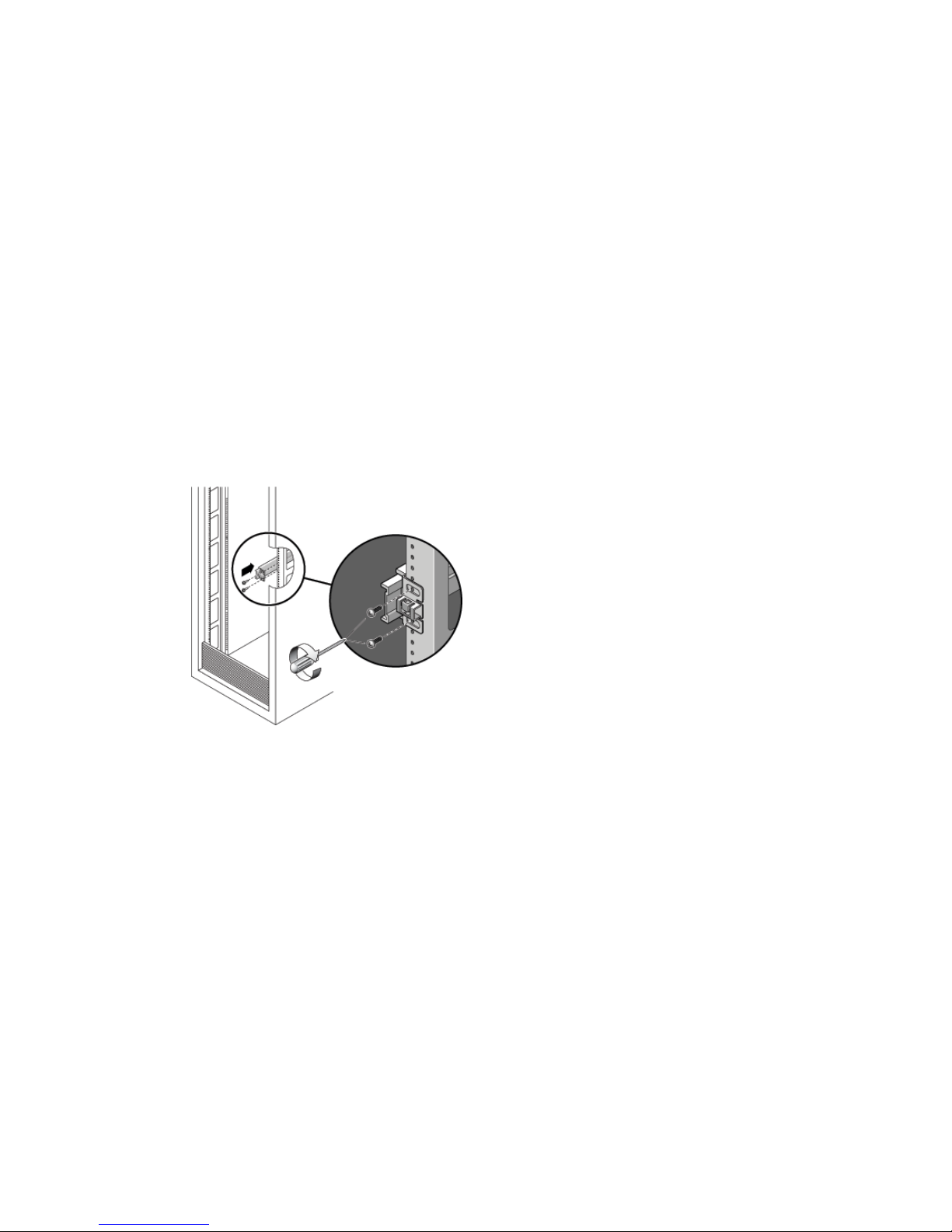
slide rail assembly are on the outside of the front and rear rack posts (as depicted
in
FIGURE 2-2).
2. Attach the slide rail assembly to the rack posts.
The method used to attach the slide rails varies depending on the type of rack:
■ If your rack has threaded mounting holes in the rack posts, determine whether
the threads are metric or standard, then insert the correct mounting screws
through the slide rail brackets and into the threaded holes.
■ If your rack does not have threaded mounting holes, insert the mounting screws
through both the slide rail brackets and rack posts, then secure them with the
caged nuts.
FIGURE 2-2 Slide Rail Assembly Mounting to Rack Post
3. Repeat for the remaining slide rail assembly.
Page 21
Chapter 2 Installing the Hardware 9
▼ To Install the Server Into the Slide Rail
Assemblies
Caution – This procedure requires a minimum of two people because of the weight
of the server. Attempting this procedure alone could result in equipment damage or
personal injury.
1. Push the slide rails into the slide rail assemblies as far as possible.
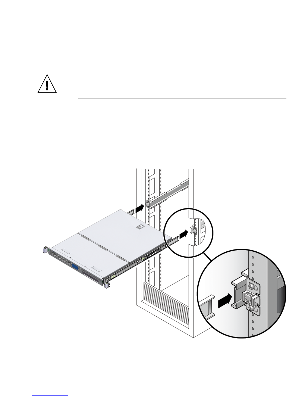
2. Raise the server so that the rear ends of the mounting brackets are aligned with
the slide rail assemblies that are mounted in the equipment rack (see
FIGURE 2-3).
3. Insert the mounting brackets into the slide rails, then push the server into the rack
until the mounting brackets encounter the slide rail stops (approximately 12 in. or
30 cm).
FIGURE 2-3 Inserting the Server With Mounting Brackets Into the Slide Rails
Page 22

10 Sun Fire V125 Server Installation Guide • September 2006
4. Simultaneously, pull and hold the slide rail release buttons on each mounting
bracket while you push the server into the rack (see
FIGURE 2-3).
FIGURE 2-4 Slide Rail Lock
5. Continue pushing until the slide rail locks on the front of the mounting brackets
engage the slide rail assemblies.
Caution – Verify that the server is securely mounted in the rack and that the slide
rails locks are engaged with the mounting brackets before continuing.
Page 23

11
CHAPTER
3
Powering On and Configuring the
Server
This chapter tells you how to power on and configure the server to suit your
application. It contains the sections:
■ “Understanding the Status Indicators” on page 11
■ “Powering On the Server” on page 11
■ “Configuring the Server” on page 13
■ “Accessing the Sun Advanced Lights Out Manager Software” on page 16
Understanding the Status Indicators
Before you power on the server, you should become familiar with the LED
indicators associated with the server itself and with various components. The server
status indicators are located on the bezel and repeated on the back panel. For more
information about the status indicators, refer to the Sun Fire V125 Server
Administration Guide.
Powering On the Server
To power on the server, you can use either the On/Standby button, located behind
the front bezel, or you can use the keyboard. Powering on from the keyboard enables
you to see system output as the server powers on.
Page 24

12 Sun Fire V125 Server Installation Guide • September 2006
▼ To Power On From the Keyboard
1. Connect the server to the power supply.
The server automatically goes into Standby power mode when it is connected to a
power source.
2. Set up a connection to the SERIAL MGT port.
For details, refer to the Sun Fire V125 Server Administration Guide.
When you switch to the ALOM prompt after initial power on, you will be logged in
as the admin user and prompted to set a password. You must set this password to
execute certain commands.
3. If you are prompted to do so, set a password for the admin user.
The password must:
■ Contain at least two alphabetic characters
■ Contain at least one numeric or one special character
■ Be at least six characters long
After the password is set, the admin user has full permissions and can execute all
ALOM command-line interface (CLI) commands.
4. Turn on power to any peripherals and external storage devices you have connected
to the server.
Read the documentation supplied with the device for specific instructions.
5. At the console prompt, type the following command to power on the server:
6. At the console prompt, type the following to access the server:
sc> poweron
sc> console
Page 25

Chapter 3 Powering On and Configuring the Server 13
▼ To Power On Using the On/Standby Button
Caution – Never move the system when the system power is on. Movement can
cause catastrophic hard drive failure. Always power off the system before moving it.
1. Connect the server to the power supply.
The server automatically goes into Standby power mode when it is connected to a
power source.
2. Turn on power to any peripherals and external storage devices you have connected
to the server.
Read the documentation supplied with the device for specific instructions.
3. Open the front bezel.
4. Press the On/Standby button.
5. Close the front bezel.
Configuring the Server
The Sun Fire server ships with the Solaris 10 OS and the Java Enterprise System
preinstalled on the hard drive. When you power on the server for the first time, a
series of questions leads you through the configuration procedure. This procedure
consists of a number of questions. The answers you give determine how the server is
configured.
In OpenBoot PROM 4.22.17, diagnostics are enabled by default. This ensures
complete diagnostic test coverage on the initial boot and after error or reset events.
This change results in increased boot time. To change the diagnostic settings after
the initial boot and after you configure the server for the first time, refer to OpenBoot
PROM Enhancements for Diagnostic Operation.
Choose the configuration that best suits your requirements from the list below and
follow the instructions in the appropriate section to power on and configure your
server.
■ “To Configure With the Server’s Details Registered at a Name Server” on page 14
■ “To Configure Without the Server’s Details Registered at a Name Server” on
page 14
■ “To Configure a Standalone Server for the First Time” on page 15
■ “To Clear the Configuration” on page 16
Page 26

14 Sun Fire V125 Server Installation Guide • September 2006
▼ To Configure With the Server’s Details
Registered at a Name Server
Note – Follow the instructions in this section only if you have a name server
installed on your network. For instructions on using a name server to automate the
process of configuring the Solaris OS on multiple servers, refer to the Solaris
Advanced Installation Guide that accompanies the Solaris OS CDs.
During booting you will be prompted for certain information. The information you
provide determines the configuration of the server.
1. Specify the type of terminal with which you are communicating with the server.
2. Specify whether you need IPv6 enabled, and then follow the instructions on the
screen.
3. Specify whether you want to enable the Kerberos Security mechanism, and then
follow the instructions on the screen.
4. When prompted, give a password (if any) for users logging in as the superuser.
▼ To Configure Without the Server’s Details
Registered at a Name Server
Follow the instructions in this section if you do not have a name server configured
on your network.
Tip – Read these instructions through before you follow them, to see what
information the system will prompt you for when you start it for the first time.
During booting you will be prompted for certain information. The information you
provide determines the configuration of the server.
1. Specify the type of terminal you are using to communicate with the server.
2. When asked if you want the server to be networked, answer Yes.
You must manually specify an IP address when prompted.
3. Specify whether the IP address is to be configured by DHCP.
4. Specify which of the Ethernet ports you intend to use as the primary Ethernet
connection.
5. Specify a host name for the server.
Page 27

Chapter 3 Powering On and Configuring the Server 15
6. If prompted, specify the IP address for the system.
The system prompts you for this address if you declined to use DHCP in Step 3.It
also asks you whether the server is to be part of a subnet, and if you answer Yes it
prompts you to provide the netmask of the subnet.
7. Specify whether you need IPv6 enabled, and then follow the instructions on the
screen.
8. Specify whether you want to enable the Kerberos Security mechanism, and then
follow the instructions on the screen.
9. Specify the name service you want the server to use.
10. Specify the name of the domain of which the server will be a part.
11. Specify whether you want the system to search the network for a name server or
whether you want it to use a particular name server.
12. If you chose to use a particular name server, specify the host name and IP address
of the name server.
13. At the name server prompt, create entries in the network administration files for
the system you are setting up.
14. At the prompt for the system you are setting up, follow the prompts to provide
time and date information.
15. When prompted, give a password (if any) for users logging in as the superuser.
▼ To Configure a Standalone Server for the First
Time
1. Specify the type of terminal you are using to communicate with the server.
2. When prompted to indicate whether you want the server to be networked, specify
No.
3. Specify a host name for the server.
4. Confirm the information you have given.
5. Specify the date and time information.
6. When prompted, give a password (if any) for users logging in as the superuser.
Page 28

16 Sun Fire V125 Server Installation Guide • September 2006
Clearing Your Configuration
If you want to start the power on process again, as if from a previously unused
server, you must clear the configuration of the server.
▼ To Clear the Configuration
1. At the Solaris OS prompt, type:
2. When prompted to confirm that you want to create a “blank” server, type y.
3. When the OpenBoot PROM prompt appears, type:
4. Follow the instructions in one of the following sections:
■ “To Configure With the Server’s Details Registered at a Name Server” on page 14
■ “To Configure Without the Server’s Details Registered at a Name Server” on
page 14
■ “To Configure a Standalone Server for the First Time” on page 15
Accessing the Sun Advanced Lights Out
Manager Software
This section contains a brief introduction to the Sun Advanced Lights Out Manager
(ALOM) software. For detailed ALOM instructions and configuration information,
refer to the Sun Advanced Lights Out Manager (ALOM) 1.6 Administration Guide.
The ALOM software is preinstalled on the server and is ready to run as soon as
power is applied to the server. However, you need to perform some basic
configuration steps to customize the ALOM software to suit your application.
# sys-unconfig
ok> boot
Page 29

Chapter 3 Powering On and Configuring the Server 17
▼ To Display the ALOM Prompt
1. Type the default keystroke sequence:
Note – When you switch to the ALOM prompt after initial power on, you will be
logged in as the admin user and prompted to set a password. You must set this
password in order to execute certain commands.
2. If you are prompted to do so, set a password for the admin user.
The password must:
■ Contain at least two alphabetic characters
■ Contain at least one numeric or one special character
■ Be at least six characters long
After you set the password, the admin user has full permissions and can execute all
ALOM CLI commands.
▼ To Display the Console Prompt
● Type:
More than one ALOM user can be connected to the server console stream at a time,
but only one user is permitted to type input characters to the console.
If another user is logged on and has write capability, you will see the message below
after issuing the console command:
# #.
sc> console
sc> Console session already in use. [view mode]
Page 30

18 Sun Fire V125 Server Installation Guide • September 2006
 Loading...