

Page 1

Sun Fire™E2900 Systems
Installation Guide
Sun Microsystems, Inc.
www.sun.com
Part No. 817-4053-15
May 2006, Revision A
Submit comments about this document at: http://www.sun.com/hwdocs/feedback
Page 2

Copyright 2006Sun Microsystems,Inc., 4150Network Circle, SantaClara, California95054, U.S.A.All rightsreserved.
Sun Microsystems,Inc. hasintellectual property rightsrelating totechnology thatis describedin thisdocument. Inparticular, andwithout
limitation, theseintellectual propertyrights mayinclude oneor more ofthe U.S.patents listedat http://www.sun.com/patentsand oneor
more additionalpatents orpending patentapplications inthe U.S.and inother countries.
This documentand theproduct towhich itpertains are distributedunder licensesrestricting theiruse, copying,distribution, and
decompilation. Nopart ofthe productor ofthis documentmay bereproducedin anyform byany meanswithout priorwritten authorizationof
Sun andits licensors,if any.
Third-party software, includingfont technology,is copyrightedand licensedfrom Sun suppliers.
Parts ofthe productmay bederived from BerkeleyBSD systems,licensed fromthe Universityof California.UNIX isa registered trademarkin
the U.S.and inother countries,exclusively licensedthrough X/OpenCompany, Ltd.
Sun, SunMicrosystems, theSun logo,AnswerBook2, docs.sun.com,Sun Fire, SunStorEdge, Netra,and Solarisare trademarksor registered
trademarks ofSun Microsystems,Inc. inthe U.S.and inother countries.
All SPARCtrademarks areused underlicense andare trademarks or registered trademarksof SPARCInternational, Inc.in theU.S. andin other
countries. Productsbearing SPARCtrademarks are basedupon anarchitecture developed by Sun Microsystems,Inc.
The OPENLOOK andSun™ GraphicalUser Interfacewas developedby SunMicrosystems, Inc.for itsusers andlicensees. Sun acknowledges
the pioneeringefforts ofXerox in researchingand developingthe conceptof visualor graphicaluser interfacesfor thecomputer industry.Sun
holds anon-exclusive licensefrom Xerox tothe XeroxGraphical UserInterface, whichlicense alsocovers Sun’slicensees whoimplement OPEN
LOOK GUIsand otherwisecomply withSun’s writtenlicense agreements.
U.S. GovernmentRights—Commercial use.Government usersare subject to the Sun Microsystems, Inc.standard licenseagreement and
applicable provisionsof theFAR andits supplements.
DOCUMENTATION IS PROVIDED "AS IS" AND ALL EXPRESS OR IMPLIED CONDITIONS, REPRESENTATIONS AND WARRANTIES,
INCLUDING ANYIMPLIED WARRANTY OFMERCHANTABILITY, FITNESSFOR A PARTICULAR PURPOSEOR NON-INFRINGEMENT,
ARE DISCLAIMED, EXCEPT TO THE EXTENT THAT SUCH DISCLAIMERS ARE HELD TO BE LEGALLY INVALID.
Copyright 2006Sun Microsystems,Inc., 4150Network Circle, SantaClara, Californie95054, Etats-Unis.Tous droitsréservés.
Sun Microsystems,Inc. ales droits depropriété intellectuelsrelatants à la technologie qui est décritdans ce document. Enparticulier,et sansla
limitation, cesdroits depropriété intellectuels peuvent inclure unou plusdes brevetsaméricains énumérésà http://www.sun.com/patents et
un oules brevetsplus supplémentaires oules applicationsde breveten attentedans lesEtats-Unis etdans lesautrespays.
Ce produitou documentest protégé parun copyrightet distribuéavec deslicences quien restreignent l’utilisation,la copie,la distribution,et la
décompilation. Aucunepartie dece produitou documentne peutêtre reproduite sousaucune forme,par quelquemoyen quece soit,sans
l’autorisation préalableet écritede Sunet deses bailleursde licence,s’il yen a.
Le logicieldétenu pardes tiers,et quicomprend latechnologie relative auxpolices decaractères, estprotégépar uncopyright etlicencié pardes
fournisseurs deSun.
Des partiesde ceproduit pourront êtredérivées dessystèmes BerkeleyBSD licenciéspar l’Universitéde Californie.UNIX estune marque
déposée auxEtats-Unis etdans d’autrespays etlicenciée exclusivementpar X/OpenCompany, Ltd.
Sun, SunMicrosystems, le logoSun, AnswerBook2,docs.sun.com, SunFire, SunStorEdge, Netra, etSolaris sontdes marquesde fabriqueou des
marques déposéesde SunMicrosystems, Inc. aux Etats-Unis et dans d’autrespays.
Toutes lesmarques SPARC sont utilisées sous licence et sont des marques defabrique oudes marquesdéposées deSPARC International,Inc.
aux Etats-Uniset dansd’autres pays.Les produits portantles marquesSPARC sont baséssur unearchitecture développéepar Sun
Microsystems, Inc.
L’interfaced’utilisation graphiqueOPEN LOOKet Sun™a étédéveloppée parSun Microsystems, Inc.pour sesutilisateurs etlicenciés. Sun
reconnaît lesefforts de pionniers de Xeroxpour larecherche et le développement du concept des interfaces d’utilisation visuelle ou graphique
pour l’industriede l’informatique.Sun détientune licensenon exclusivede Xeroxsur l’interfaced’utilisation graphiqueXerox,cette licence
couvrant égalementles licenciéesde Sunqui mettenten placel’interface d’utilisation graphiqueOPEN LOOKet quien outrese conforment
aux licencesécrites deSun.
LA DOCUMENTATION EST FOURNIE "EN L’ÉTAT" ET TOUTES AUTRES CONDITIONS, DECLARATIONS ET GARANTIES EXPRESSES
OU TACITES SONT FORMELLEMENTEXCLUES, DANSLA MESUREAUTORISEE PARLA LOIAPPLICABLE, YCOMPRIS NOTAMMENT
TOUTE GARANTIE IMPLICITE RELATIVE A LA QUALITE MARCHANDE, A L’APTITUDE A UNE UTILISATION PARTICULIERE OU A
L’ABSENCE DE CONTREFAÇON.
Please
Recycle
Page 3

Contents
Regulatory Compliance Statements xi
Safety Agency Compliance Statements xv
Preface xxvii
1. Physical Installation 1–1
1.1 Installing Slides and Rails 1–2
1.1.1 Adjusting the Rail Assembly 1–3
1.1.2 Installing the Inner Slides on the System 1–4
1.1.3 Preparing the Rails for Two-Post Installations 1–6
1.1.4 Installing the Rail Assemblies in a Sun Fire/StorEdge Cabinet 1–7
1.1.4.1 Installing the Rail Assemblies in the Bottom Position
1–7
1.1.4.2 Installing the Rail Assemblies in the Top Position 1–8
1.1.5 Installing the Rail Assemblies in a Sun Rack 900 Cabinet 1–9
1.1.5.1 Installing the Rail Assemblies in the Bottom Position
1–9
1.1.5.2 Installing the Rail Assemblies in the Top Position 1–10
1.1.6 Installing the Rail Assemblies in a 19-Inch Four-Post Cabinet 1–11
1.1.7 Installing the Rail Assemblies in a 19-inch Two-Post Rack 1–12
1.2 Installing the System in a Cabinet 1–13
iii
Page 4

1.2.1 Preparing to Install the System in the Cabinet 1–13
1.2.2 Mounting the System in the Cabinet 1–15
1.3 Installing Slide Rail Locking Nuts 1–19
1.4 Installing the Cable Management Arm 1–21
1.4.1 Installing the CMA–Lite 1–22
1.4.2 Installing the CMA–800. 1–23
1.5 Connecting Sun Fire V1280/Netra 1280 Power Cables 1–30
1.6 Connecting Consoles to the System Controller 1–32
1.6.1 Connecting the Initial Administrative Console 1–33
1.6.2 Connecting the Administrative Console 1–35
1.7 Connecting the I/O Assemblies 1–35
1.8 Powering On the System 1–35
1.9 Powering Off the System 1–36
1.10 Installing Additional Hardware 1–36
1.11 Installing Additional Peripheral Devices 1–37
A. External Connections A–1
A.1 I/O Slots A–2
A.1.1 PCI IB_SSC Assemblies A–2
A.1.2 PCI+ IB_SSC Assemblies A–2
A.1.3 PCI-X IB_SSC Assemblies A–2
A.2 SCSI Connector A–3
A.2.1 SCSI Implementation A–4
A.3 Alarms Port A–5
A.4 LOM Serial Ports A–6
A.4.1 Using a DB-25 Adapter for Your Serial Link A–7
A.4.2 Using a DB-9 Adapter for Your Serial Link A–8
A.4.2.1 Connecting to a Male 9-Pin D-Type Serial Port A–8
A.5 10/100 LOM Ethernet Port A–9
iv Sun Fire E2900 Systems Installation Guide • May 2006
Page 5

A.5.1 Twisted-Pair Ethernet Cable-Type Connectivity A–9
A.6 Net0/Net1 Ethernet Ports A–10
Contents v
Page 6

vi Sun Fire E2900 Systems Installation Guide • May 2006
Page 7

Figures
FIGURE 1-1 Rail Assembly (Standard Configuration) 1–3
FIGURE 1-2 Spring Clips and Cutouts 1–5
FIGURE 1-3 Rail Assembly (Modified for Two-Post Installation) 1–6
FIGURE 1-4 Installing the Rails in a Sun Fire Cabinet 1–8
FIGURE 1-5 Installing the Rails in a Sun Rack 900 Cabinet or 19-Inch Four-Post Cabinet 1–10
FIGURE 1-6 Releasing the Door Hinge Mechanism 1–13
FIGURE 1-7 Removing the Shipping Cradle Bolts 1–14
FIGURE 1-8 Inserting the Lifting Device into the Shipping Cradle 1–15
FIGURE 1-9 Aligning the Slides 1–16
FIGURE 1-10 Removing the Shipping Cradle 1–17
FIGURE 1-11 Pushing the System into the System Cabinet 1–18
FIGURE 1-12 Tightening the Securing Screws 1–18
FIGURE 1-13 Inserting and Tightening the Slide Rail Spacers 1–20
FIGURE 1-14 Inserting and Tightening the Slide Rail Locking Nut 1–20
FIGURE 1-15 Bracket Mounting Holes 1–21
FIGURE 1-16 CMA–Lite Cable Management Arm 1–22
FIGURE 1-17 Upper/Lower CMA Arms and Left Hand/Right Hand T-Brackets 1–23
FIGURE 1-18 Upper/Lower Pivot Bracket Mounting Holes 1–24
FIGURE 1-19 Attachment of Upper CMA Arm and Pivot Bracket 1–25
FIGURE 1-20 Attachment of Lower CMA Arm and Pivot Bracket 1–26
vii
Page 8

FIGURE 1-21 Attaching Left Hand T-Bracket 1–27
FIGURE 1-22 Attachment of Right-Hand T-Bracket 1–28
FIGURE 1-23 Attachment of Upper/Lower CMA Arms to T-Bracket 1–29
FIGURE 1-24 System Controller and I/O Assembly Locations 1–34
FIGURE A-1 External I/O Connections—Sun Fire V1280/Netra 1280 Systems (Rear View) A–1
FIGURE A-2 68-Pin SCSI Connector A–3
FIGURE A-3 DB-15 (Male) Alarms Service Port Connector A–5
FIGURE A-4 RJ-45 Serial Connectors A–6
FIGURE A-5 RJ-45 TPE Socket A–9
FIGURE A-6 RJ-45 Gigabit Ethernet Connectors A–10
viii Sun Fire E2900 Systems Installation Guide • May 2006
Page 9

Tables
TABLE A-1 68-Pin SCSI Connector Pinout A–3
TABLE A-2 68-Pin SCSI Connector Pinout (continued) A–4
TABLE A-3 Alarms Service Port Connector Pinout A–5
TABLE A-4 RJ-45 Serial Connector Pinout A–6
TABLE A-5 Default Settings for Connecting to Serial A A–7
TABLE A-6 Pin Interconnections Performed by the Sun DB-25 Adapter A–7
TABLE A-7 Pin Interconnections Performed by a DB-9 (9-pin) Adapter A–8
TABLE A-8 Twisted-pair Ethernet Connector Pinout A–9
TABLE A-9 TPE STP-5 Cable Lengths A–9
TABLE A-10 RJ-45 Gigabit Ethernet Connector Pinout A–10
ix
Page 10

x Sun Fire E2900 Systems Installation Guide • May 2006
Page 11

Regulatory Compliance Statements
Your Sun product is marked to indicate its compliance class:
• Federal Communications Commission (FCC) — USA
• Industry Canada Equipment Standard for Digital Equipment (ICES-003) — Canada
• Voluntary Control Council for Interference (VCCI) — Japan
• Bureau of Standards Metrology and Inspection (BSMI) — Taiwan
Please read the appropriate section that corresponds to the marking on your Sun product before attempting to install the
product.
FCC Class A Notice
This device complies with Part 15 of the FCC Rules. Operation is subject to the following two conditions:
1. This device may not cause harmful interference.
2. This device must accept any interference received, including interference that may cause undesired operation.
Note: This equipment has been tested and found to comply with the limits for a Class A digital device, pursuant to Part 15 of
the FCC Rules. These limits are designed to provide reasonable protection against harmful interference when the equipment
is operated in a commercial environment. This equipment generates, uses, and can radiate radio frequency energy, and if it is
not installed and used in accordance with the instruction manual, it may cause harmful interference to radio communications.
Operation of this equipment in a residential areais likely tocause harmful interference,in which casethe user willbe required
to correct the interference at his own expense.
Modifications: Any modifications made to this device that are notapproved bySun Microsystems,Inc. mayvoid theauthority
granted to the user by the FCC to operate this equipment.
FCC Class B Notice
This device complies with Part 15 of the FCC Rules. Operation is subject to the following two conditions:
1. This device may not cause harmful interference.
2. This device must accept any interference received, including interference that may cause undesired operation.
Note: This equipment has been tested and found to comply with the limits for a Class B digital device, pursuant to Part 15 of
the FCC Rules. These limits are designed to provide reasonable protection against harmful interference in a residential
installation. This equipment generates, uses and can radiate radio frequency energy and, if not installed and used in
accordance with the instructions, may cause harmful interference to radio communications. However, there is no guarantee
that interference will not occur in a particular installation. If this equipment does cause harmful interference to radio or
television reception,which can bedetermined by turningthe equipment off and on, the user is encouraged to try to correctthe
interference by one or more of the following measures:
• Reorient or relocate the receiving antenna.
• Increase the separation between the equipment and receiver.
• Connect the equipment into an outlet on a circuit different from that to which the receiver is connected.
• Consult the dealer or an experienced radio/television technician for help.
Modifications: Any modifications made to this device that are notapproved bySun Microsystems,Inc. mayvoid theauthority
granted to the user by the FCC to operate this equipment.
xi
Page 12

ICES-003 Class A Notice - Avis NMB-003, Classe A
This Class A digital apparatus complies with Canadian ICES-003.
Cet appareil numérique de la classe A est conforme à la norme NMB-003 du Canada.
ICES-003 Class B Notice - Avis NMB-003, Classe B
This Class B digital apparatus complies with Canadian ICES-003.
Cet appareil numérique de la classe B est conforme à la norme NMB-003 du Canada.
xii Sun Fire E2900 Systems Installation Guide • May 2006
Page 13

BSMI Class A Notice
The following statement is applicable to products shipped to Taiwan and marked as Class A on the product compliance
label.
T33012
GOST-R Certification Mark
Regulatory Compliance Statements xiii
Page 14

xiv Sun Fire E2900 Systems Installation Guide • May 2006
Page 15

Safety Agency Compliance Statements
Read this section before beginning any procedure. The
following text provides safety precautions to follow when
installing a Sun Microsystems product.
Safety Precautions
For your protection, observe the following safety
precautions when setting up your equipment:
■ Follow all cautions and instructions marked on the
equipment.
■ Ensure that the voltage and frequency of your power
source match the voltage and frequency inscribed on
the equipment’s electrical rating label.
■ Never push objects of any kind through openings in
the equipment. Dangerous voltages may be present.
Conductive foreign objects could produce a short
circuit that could cause fire, electric shock, or damage
to your equipment.
Depending on the type of power switch your device has,
one of the following symbols may be used:
On – Applies AC power to the system.
Off – Removes AC power from the system.
Standby – The On/Standby switch is in the
standby position.
Modifications to Equipment
Do not make mechanical or electrical modifications to the
equipment. Sun Microsystems is not responsible for
regulatory compliance of a modified Sun product.
Placement of a Sun Product
Symbols
The following symbols may appear in this book:
Caution – There is a risk of personal injury
and equipment damage. Follow the
instructions.
Caution – Hot surface. Avoid contact.
Surfaces are hot and may cause personal
injury if touched.
Caution – Hazardous voltages are present. To
reduce the risk of electric shock and danger to
personal health, follow the instructions.
Caution – Do not block or cover the openings
of your Sun product. Never place a Sun
product near a radiator or heat register.
Failure to follow these guidelines can cause
overheating and affect the reliability of your
Sun product.
Noise Level
In compliance with the requirements defined in DIN 45635
Part 1000, the workplace-dependent noise level of this
product is less than 70 db(A).
xv
Page 16

SELV Compliance
Safety status of I/O connections comply to SELV
requirements.
Power Cord Connection
Caution – Sun products are designed to work
with power systems having a grounded
neutral (grounded return for DC-powered
products). To reduce the risk of electric shock,
do not plug Sun products into any other type
of power system. Contact your facilities
manager or a qualified electrician if you are
not sure what type of power is supplied to
your building.
Caution – Not all power cords have the same
current ratings. Household extension cords do
not have overload protection and are not
meant for use with computer systems. Do not
use household extension cords with your Sun
product.
The following caution applies only to devices with a
Standby power switch:
Caution – The power switch of this product
functions as a standby type device only. The
power cord serves as the primary disconnect
device for the system. Be sure to plug the
power cord into a grounded power outlet that
is nearby the system and is readily accessible.
Do not connect the power cord when the
power supply has been removed from the
system chassis.
The followingcaution applies only to deviceswith multiple
power cords:
Caution – For products with multiple power
cords, all power cords must be disconnected
to completely remove power from the system.
Battery Warning
Caution – There is danger of explosion if
batteries are mishandled or incorrectly
replaced. On systems with replaceable
batteries, replace only with the same
manufacturer and type or equivalent type
recommended by the manufacturer per the
instructions provided in the product service
manual. Do not disassemble batteries or
attempt to recharge them outside the system.
Do not dispose of batteries in fire. Dispose of
batteries properly in accordance with the
manufacturer’s instructions and local
regulations. Note that on Sun CPU boards,
there is a lithium battery molded into the realtime clock. These batteries are not customer
replaceable parts.
System Unit Cover
You must remove the cover of your Sun computer system
unit to add cards, memory, or internal storage devices. Be
sure toreplace the cover before powering on yourcomputer
system.
Caution – Do not operate Sun products
without the cover in place. Failure to take this
precaution may result in personal injury and
system damage.
Rack System Warning
The following warnings apply to Racks and Rack Mounted
systems.
Caution – For safety, equipment should
always be loaded from the bottom up. That is,
install the equipment that will be mounted in
the lowest part of the rack first, then the next
higher systems, etc.
Caution – To prevent the rack from tipping
during equipment installation, the anti-tilt bar
on the rack must be deployed.
xvi Sun Fire E2900 Systems Installation Guide • May 2006
Page 17

Caution – To prevent extreme operating
temperature within the rack insure that the
maximum temperature does not exceed the
product’s ambient rated temperatures.
Conformité aux normes de sécurité
Veuillez lire attentivement cette section avant de
commencer. Ce texte traite des mesures de sécurité qu’il
convient de prendre pour l’installation d’un produit Sun
Microsystems.
Caution – To prevent extreme operating
temperatures due to reduced airflow
consideration should be made to the amount
of air flow that is required for a safe operation
of the equipment.
Laser Compliance Notice
Sun products that use laser technology comply withClass 1
laser requirements.
Class 1 Laser Product
Luokan 1 Laserlaite
Klasse 1 Laser Apparat
Laser Klasse 1
CD and DVD Devices
The following caution applies to CD, DVD, and other
optical devices.
Caution – Use of controls, adjustments, or the
performance of procedures other than those
specified herein may result in hazardous
radiation exposure.
Mesures de sécurité
Pour votre sécurité, nous vous recommandons de suivre
scrupuleusement lesmesures de sécuritéci-dessous lorsque
vous installez votre matériel:
■ Suivez tous les avertissements et toutes les
instructions inscrites sur le matériel.
■ Assurez-vous que la tension et la fréquence de votre
source d'alimentation correspondent à la tension et à
la fréquence indiquées sur l'étiquette de la tension
électrique nominale du matériel
■ N'introduisez jamais d'objets quels qu'ils soient dans
les ouvertures de l'équipement. Vous pourriez vous
trouver en présence de hautes tensions dangereuses.
Tout objet étranger conducteur risque de produire un
court-circuit pouvant présenter un risque d'incendie
ou de décharge électrique, ou susceptible
d'endommager le matériel.
Symboles
Vous trouverez ci-dessous la signification des différents
symboles utilisés:
Attention – Vous risquez d'endommager le
matériel ou de vous blesser. Veuillez suivre les
instructions.
Attention – Surfaces brûlantes. Evitez tout
contact. Les surfaces sont brûlantes. Vous
risquez de vous blesser si vous les touchez.
Attention – Tensions dangereuses. Pour
réduire les risques de décharge électrique et
de danger physique, observez les consignes
indiquées.
Safety Agency Compliance Statements xvii
Page 18

Selon le type d'interrupteur marche/arrêt dont votre
appareil est équipé, l'un des symboles suivants sera utilisé:
Marche – Met le système sous tension
alternative.
Arret – Met le système hors tension
alternative.
Veilleuse – L'interrupteur Marche/Veille est
sur la position de veille.
Connexion du cordon d’alimentation
Attention – Les produits Sun sont conçus
pour fonctionner avec des systèmes
d'alimentation équipés d'un conducteur
neutre relié à la terre (conducteur neutre pour
produits alimentés en CC). Pour réduire les
risques de décharge électrique, ne branchez
jamais les produits Sun sur une source
d'alimentation d'un autre type. Contactez le
gérant de votre bâtiment ou un électricien
agréé si vous avez le moindre doute quant au
type d'alimentation fourni dans votre
bâtiment.
Modification du matériel
N'apportez aucune modification mécanique ou électrique
au matériel. Sun Microsystems décline toute responsabilité
quant à la non-conformité éventuelle d'un produit Sun
modifié.
Positionnement d’un produit Sun
Attention – Evitez d'obstruer ou de recouvrir
les orifices de votre produit Sun. N'installez
jamais un produit Sun près d'un radiateur ou
d'une source de chaleur. Si vous ne respectez
pas ces consignes, votre produit Sun risque de
surchauffer et son fonctionnement en sera
altéré.
Niveau de pression acoustique
Le niveau de pression acoustique du lieu de travail définie
par lanorme DIN 45 635 Part 1000 doitêtre au maximum de
70 db(A).
Conformité SELV
Le niveau de sécurité des connexions E/S est conforme aux
normes SELV.
Attention – Tous les cordons d'alimentation
ne présentent pas les mêmes caractéristiques
électriques. Les cordons d'alimentation à
usage domestique ne sont pas protégés contre
les surtensions et ne sont pas conçus pour être
utilisés avec des ordinateurs. N'utilisez jamais
de cordon d'alimentation à usage domestique
avec les produits Sun.
L'avertissement suivant s'applique uniquement aux
systèmes équipés d'un interrupteur Veille:
Attention – L'interrupteur d'alimentation de
ce produit fonctionne uniquement comme un
dispositif de mise en veille. Le cordon
d'alimentation constitue le moyen principal de
déconnexion de l'alimentation pour le
système. Assurez-vous de le brancher dans
une prise d'alimentation mise à la terre près
du système et facile d'accès. Ne le branchez
pas lorsque l'alimentation électrique ne se
trouve pas dans le châssis du système.
L'avertissement suivant s'applique uniquement aux
systèmes équipés de plusieurs cordons d'alimentation:
Attention – Pour mettre un système équipé de
plusieurs cordons d'alimentation hors tension,
il est nécessaire de débrancher tous les
cordons d'alimentation.
xviii Sun Fire E2900 Systems Installation Guide • May 2006
Page 19

Mise en garde relative aux batteries
Attention – Les batteries risquent d’exploser
en cas de manipulation maladroite ou de
remplacement incorrect. Pour les systèmes
dont les batteries sont remplaçables, effectuez
les remplacements uniquement selon le
modèle du fabricant ou un modèle équivalent
recommandé par le fabricant, conformément
aux instructions fournies dans le manuel de
service du système. N’essayez en aucun cas de
démonter les batteries, ni de les recharger hors
du système. Ne les jetez pas au feu. Mettez-les
au rebut selon les instructions du fabricant et
conformément à la législation locale en
vigueur. Notez que sur les cartes processeur
de Sun, une batterie au lithium a été moulée
dans l'horloge temps réel. Les batteries ne sont
pas des pièces remplaçables par le client.
Couvercle de l'unité
Pour ajouterdes cartes,de la mémoire ou des périphériques
de stockage internes, vous devez retirer le couvercle de
votre système Sun. Remettez le couvercle supérieur en
place avant de mettre votre système sous tension.
Attention – Afin d'éviter que le rack ne
penche pendant l'installation du matériel, tirez
la barre anti-basculement du rack.
Attention – Pour éviter des températures de
fonctionnement extrêmes dans le rack,
assurez-vous que la température maximale ne
dépasse pas la fourchette de températures
ambiantes du produit déterminée par le
fabricant.
Attention – Afin d'empêcher des
températures de fonctionnement extrêmes
provoquées par une aération insuffisante,
assurez-vous de fournir une aération
appropriée pour un fonctionnement du
matériel en toute sécurité
Avis de conformité des appareils laser
Les produitsSun quifont appelaux technologieslasers sont
conformes aux normes de la classe 1 en la matière.
Attention – Ne mettez jamais des produits
Sun sous tension si leur couvercle supérieur
n'est pas mis en place. Si vous ne prenez pas
ces précautions, vous risquez de vous blesser
ou d'endommager le système.
Mise en garde relative au système en rack
La mise en garde suivante s'applique aux racks et aux
systèmes montés en rack.
Attention – Pour des raisons de sécurité, le
matériel doit toujours être chargé du bas vers
le haut. En d'autres termes, vous devez
installer, en premier, le matériel qui doit se
trouver dans la partie la plus inférieure du
rack, puis installer le matériel sur le niveau
suivant, etc.
Class 1 Laser Product
Luokan 1 Laserlaite
Klasse 1 Laser Apparat
Laser Klasse 1
Périphériques CD et DVD
L'avertissement suivant s'applique aux périphériques CD,
DVD et autres périphériques optiques:
Attention – L'utilisation de contrôles et de
réglages ou l'application de procédures autres
que ceux spécifiés dans le présent document
peuvent entraîner une exposition à des
radiations dangereuses.
Safety Agency Compliance Statements xix
Page 20

Einhaltung sicherheitsbehördlicher Vorschriften
Lesen Sie vor dem Ausführen von Arbeiten diesen
Abschnitt. Im folgenden Text werden Sicherheitsvorkehrungen beschrieben, die Sie bei der Installation eines
Sun Microsystems-Produkts beachten müssen.
Sicherheitsvorkehrungen
Treffen Sie zu Ihrem eigenen Schutzbei der Installation des
Geräts die folgenden Sicherheitsvorkehrungen:
■ Beachten Sie alle auf den Geräten angebrachten
Warnhinweise und Anweisungen.
■ Stellen Sie sicher, dass Spannung und Frequenz der
Stromversorgung den Nennleistungen auf dem am
Gerät angebrachten Etikett entsprechen.
■ Führen Sie niemals Fremdobjekte in die Öffnungen
am Gerät ein. Es können gefährliche Spannungen
anliegen. Leitfähige Fremdobjekte können einen
Kurzschluss verursachen, der einen Brand, Stromschlag oder Geräteschaden herbeiführen kann.
Je nach Netzschaltertyp an Ihrem Gerät kann eines der
folgenden Symbole verwendet werden:
Ein – Versorgt das System mit Wechselstrom.
Aus– Unterbricht die Wechselstromzufuhr
zum Gerät.
Wartezustand – Der Ein-/Standby-Netzschalter befindet sich in der Standby-Position.
Modifikationen des Geräts
Nehmen Sie keine elektrischen oder mechanischen
Gerätemodifikationen vor. Sun Microsystems ist für die
Einhaltung der Sicherheitsvorschriften von modifizierten
Sun-Produkten nicht haftbar.
Symbole
Die Symbole in diesem Handbuch haben folgende
Bedeutung:
Achtung – Gefahr von Verletzung und
Geräteschaden. Befolgen Sie die Anweisungen.
Achtung – Heiße Oberfläche. Nicht berühren,
da Verletzungsgefahr durch heiße Oberfläche
besteht.
Achtung – Gefährliche Spannungen. Befolgen
Sie die Anweisungen, um Stromschläge und
Verletzungen zu vermeiden.
Aufstellung von Sun-Geräten
Achtung – Geräteöffnungen Ihres SunProdukts dürfen nicht blockiert oder
abgedeckt werden. Sun-Geräte sollten niemals
in der Nähe von Heizkörpern oder Heißluftklappen aufgestellt werden. Die Nichtbeachtung dieser Richtlinien kann Überhitzung
verursachen und die Zuverlässigkeit Ihres
Sun-Geräts beeinträchtigen.
Lautstärke
Gemäß denin DIN 45 635 Teil1000 definiertenVorschriften
beträgt diearbeitsplatzbedingte Lautstärke dieses Produkts
weniger als 70 dB(A).
SELV-Konformität
Der Sicherheitsstatus der E/A-Verbindungen entspricht
den SELV-Anforderungen.
xx Sun Fire E2900 Systems Installation Guide • May 2006
Page 21

Anschluss des Netzkabels
Warnung bezüglich Batterien
Achtung – Sun-Geräte sind für
Stromversorgungssysteme mit einem
geerdeten neutralen Leiter (geerdeter
Rückleiter bei gleichstrombetriebenen
Geräten) ausgelegt. Um die Gefahr von
Stromschlägen zu vermeiden, schließen Sie
das Gerät niemals an andere Stromversorgungssysteme an. Wenden Sie sich an den
zuständigen Gebäudeverwalter oder an einen
qualifizierten Elektriker, wenn Sie nicht sicher
wissen, an welche Art von Stromversorgungssystem Ihr Gebäude angeschlossen ist.
Achtung – Nicht alle Netzkabel verfügen
über die gleichen Nennwerte. Herkömmliche,
im Haushalt verwendete Verlängerungskabel
besitzen keinen Überlastschutz und sind
daher für Computersysteme nicht geeignet.
Verwenden Sie bei Ihrem Sun-Produkt keine
Haushalts-Verlängerungskabel.
Die folgende Warnung gilt nur für Geräte mit StandbyNetzschalter:
Achtung – Beim Netzschalter dieses Geräts
handelt es sich nur um einen Ein/StandbySchalter. Zum völligen Abtrennen des Systems
von der Stromversorgung dient hauptsächlich
das Netzkabel. Stellen Sie sicher, dass das
Netzkabel an eine frei zugängliche geerdete
Steckdose in der Nähe des Systems angeschlossen ist. Schließen Sie das Stromkabel
nicht an, wenn die Stromversorgung vom
Systemchassis entfernt wurde.
Die folgende Warnung gilt nur für Geräte mit mehreren
Netzkabeln:
Achtung – Bei unsachgemäßer Handhabung
oder nicht fachgerechtem Austausch der
Batterien besteht Explosionsgefahr. Verwenden Sie bei Systemen mit austauschbaren
Batterien ausschließlich Ersatzbatterien
desselben Typs und Herstellers bzw. einen
entsprechenden, vom Hersteller gemäß den
Anweisungen im Service-Handbuch des
Produkts empfohlenen Batterietyp. Versuchen
Sie nicht, die Batterien auszubauen oder
außerhalb des Systems wiederaufzuladen.
Werfen Sie die Batterien nicht ins Feuer.
Entsorgen Sie die Batterien entsprechend den
Anweisungen des Herstellers und den vor Ort
geltenden Vorschriften. CPU-Karten von Sun
verfügen über eine Echtzeituhr mit integrierter Lithiumbatterie. Diese Batterie darf nur
von einem qualifizierten Servicetechniker ausgewechselt werden.
Gehäuseabdeckung
Sie müssen die Abdeckung Ihres Sun-Computersystems
entfernen, um Karten, Speicher oderinterne Speichergeräte
hinzuzufügen. Bringen Sie vor dem Einschalten des
Systems die Gehäuseabdeckung wieder an.
Achtung – Nehmen Sie Sun-Geräte nicht ohne
Abdeckung in Betrieb. Die Nichtbeachtung
dieses Warnhinweises kann Verletzungen oder
Geräteschaden zur Folge haben.
Warnungen bezüglich in Racks eingebauter Systeme
Die folgenden Warnungen gelten für Racks und in Racks
eingebaute Systeme:
Achtung – Bei Produkten mit mehreren Netzkabeln müssen alle Netzkabel abgetrennt werden, um das System völlig von der Stromversorgung zu trennen.
Achtung – Aus Sicherheitsgründen sollten
sämtliche Geräte von unten nach oben in
Racks eingebaut werden. Installieren Sie also
zuerst die Geräte, die an der untersten
Position im Rack eingebaut werden, gefolgt
von den Systemen, die an nächsthöherer Stelle
eingebaut werden, usw.
Safety Agency Compliance Statements xxi
Page 22

Achtung – Verwenden Sie beim Einbau den
Kippschutz am Rack, um ein Umkippen zu
vermeiden.
Normativas de seguridad
Lea esta sección antes de realizar cualquier operación. En
ella seexplican las medidasde seguridad que debe tomaral
instalar un producto de Sun Microsystems.
Achtung – Um extreme Betriebstemperaturen
im Rack zu vermeiden, stellen Sie sicher, dass
die Maximaltemperatur die Nennleistung der
Umgebungstemperatur für das Produkt nicht
überschreitet
Achtung – Um extreme Betriebstemperaturen
durch verringerte Luftzirkulation zu vermeiden, sollte die für den sicheren Betrieb des
Geräts erforderliche Luftzirkulation eingesetzt
werden.
Hinweis zur Laser-Konformität
Sun-Produkte, die die Laser-Technologie verwenden,
entsprechen den Laser-Anforderungen der Klasse 1.
Class 1 Laser Product
Luokan 1 Laserlaite
Klasse 1 Laser Apparat
Laser Klasse 1
Medidas de seguridad
Para su protección, tome las medidas de seguridad
siguientes durante la instalación del equipo:
■ Siga todos los avisos e instrucciones indicados en el
equipo.
■ Asegúrese de que el voltaje y frecuencia de la fuente
de alimentación coincidan con el voltaje y frecuencia
indicados en la etiqueta de clasificación eléctrica del
equipo.
■ No introduzca objetos de ningún tipo por las rejillas
del equipo, ya que puede quedar expuesto a voltajes
peligrosos. Los objetos conductores extraños pueden
producir cortocircuitos y, en consecuencia, incendios,
descargas eléctricas o daños en el equipo.
Símbolos
En este documento aparecen los siguientes símbolos:
Precaución – Existe el riesgo de que se
produzcan lesiones personales y daños en el
equipo. Siga las instrucciones.
Precaución – Superficie caliente. Evite todo
contacto. Las superficies están calientes y
pueden causar lesiones personales si se tocan.
CD- und DVD-Geräte
Die folgende Warnung gilt für CD-, DVD- und andere
optische Geräte:
Achtung – Die hier nicht aufgeführte
Verwendung von Steuerelementen,
Anpassungen oder Ausführung von
Vorgängen kann eine gefährliche
Strahlenbelastung verursachen.
xxii Sun Fire E2900 Systems Installation Guide • May 2006
Precaución – Voltaje peligroso. Para reducir
el riesgo de descargas eléctricas y lesiones
personales, siga las instrucciones.
Page 23

En función del tipo de interruptor de alimentación del que
disponga el dispositivo, se utilizará uno de los símbolos
siguientes:
Encendido – Suministra alimentación de CA
al sistema.
Apagado – Corta la alimentación de CA del
sistema.
Espera – El interruptor de encendido/espera
está en la posición de espera.
Conexión del cable de alimentación
Precaución – Los productos Sun se han
diseñado para funcionar con sistemas de
alimentación que cuenten con un conductor
neutro a tierra (con conexión a tierra de
regreso para los productos con alimentación
de CC). Para reducir el riesgo de descargas
eléctricas, no conecte ningún producto Sun a
otro tipo de sistema de alimentación. Póngase
en contacto con el encargado de las
instalaciones de su empresa o con un
electricista cualificado en caso de que no esté
seguro del tipo de alimentación del que se
dispone en el edificio.
Modificaciones en el equipo
No realicemodificaciones de tipo mecánico ni eléctrico en el
equipo. Sun Microsystems no se hace responsable del
cumplimiento de normativas en caso de que un producto
Sun se haya modificado.
Colocación de un producto Sun
Precaución – No obstruya ni tape las rejillas
del producto Sun. Nunca coloque un producto
Sun cerca de radiadores ni fuentes de calor. Si
no sigue estas indicaciones, el producto Sun
podría sobrecalentarse y la fiabilidad de su
funcionamiento se vería afectada.
Nivel de ruido
De conformidad con los requisitos establecidos en el
apartado 1000 de la norma DIN 45635, el nivel de ruido en
el lugarde trabajoproducido poreste productoes menorde
70 db(A).
Cumplimiento de la normativa para instalaciones SELV
Las condiciones de seguridad de las conexiones de entrada
y salidacumplen losrequisitos para instalaciones SELV (del
inglés Safe Extra Low Voltage, voltaje bajo y seguro).
Precaución – No todos los cables de
alimentación tienen la misma clasificación
eléctrica. Los alargadores de uso doméstico no
cuentan con protección frente a sobrecargas y
no están diseñados para su utilización con
sistemas informáticos. No utilice alargadores
de uso doméstico con el producto Sun.
La siguiente medida solamente se aplica a aquellos
dispositivos que dispongan de un interruptor de
alimentación de espera:
Precaución – El interruptor de alimentación
de este producto funciona solamente como un
dispositivo de espera. El cable de alimentación
hace las veces de dispositivo de desconexión
principal del sistema. Asegúrese de que
conecta el cable de alimentación a una toma
de tierra situada cerca del sistema y de fácil
acceso. No conecte el cable de alimentación si
la unidad de alimentación no se encuentra en
el bastidor del sistema.
La siguiente medida solamente se aplica a aquellos
dispositivos que dispongan de varios cables de
alimentación:
Safety Agency Compliance Statements xxiii
Page 24

Precaución – En los productos que cuentan
con varios cables de alimentación, debe
desconectar todos los cables de alimentación
para cortar por completo la alimentación
eléctrica del sistema.
Precaución – Por seguridad, siempre deben
montarse los equipos de abajo arriba. A saber,
primero debe instalarse el equipo que se
situará en el bastidor inferior; a continuación,
el que se situará en el siguiente nivel, etc.
Advertencia sobre las baterías
Precaución – Si las baterías no se manipulan
o reemplazan correctamente, se corre el riesgo
de que estallen. En los sistemas que cuentan
con baterías reemplazables, reemplácelas sólo
con baterías del mismo fabricante y el mismo
tipo, o un tipo equivalente recomendado por
el fabricante, de acuerdo con las instrucciones
descritas en el manual de servicio del
producto. No desmonte las baterías ni intente
recargarlas fuera del sistema. No intente
deshacerse de las baterías echándolas al fuego.
Deshágase de las baterías correctamente de
acuerdo con las instrucciones del fabricante y
las normas locales. Tenga en cuenta que en las
placas CPU de Sun, hay una batería de litio
incorporada en el reloj en tiempo real. Los
usuarios no deben reemplazar este tipo de
baterías.
Cubierta de la unidad del sistema
Debe extraer la cubierta de la unidad del sistema
informático Sun para instalar tarjetas, memoria o
dispositivos de almacenamiento internos. Vuelva a colocar
la cubierta antes de encender el sistema informático.
Precaución – Para evitar que el bastidor se
vuelque durante la instalación del equipo,
debe extenderse la barra antivolcado del
bastidor.
Precaución – Para evitar que se alcance una
temperatura de funcionamiento extrema en el
bastidor, asegúrese de que la temperatura
máxima no sea superior a la temperatura
ambiente establecida como adecuada para el
producto.
Precaución – Para evitar que se alcance una
temperatura de funcionamiento extrema
debido a una circulación de aire reducida,
debe considerarse la magnitud de la
circulación de aire requerida para que el
equipo funcione de forma segura.
Aviso de cumplimiento de la normativa para la utilización de láser
Los productos Sunque utilizantecnología lásercumplen los
requisitos establecidos para los productos láser de clase 1.
Precaución – No ponga en funcionamiento
los productos Sun que no tengan colocada la
cubierta. De lo contrario, puede sufrir lesiones
personales y ocasionar daños en el sistema.
Advertencia sobre el sistema en bastidor
Las advertencias siguientes se aplican a los sistemas
montados en bastidor y a los propios bastidores.
xxiv Sun Fire E2900 Systems Installation Guide • May 2006
Class 1 Laser Product
Luokan 1 Laserlaite
Klasse 1 Laser Apparat
Laser Klasse 1
Page 25

Dispositivos de CD y DVD
La siguiente medida se aplica a los dispositivos de CD y
DVD, así como a otros dispositivos ópticos:
Precaución – La utilización de controles,
ajustes o procedimientos distintos a los aquí
especificados puede dar lugar a niveles de
radiación peligrosos.
Nordic Lithium Battery Cautions
Norge
Advarsel – Litiumbatteri — Eksplosjonsfare.
Ved utskifting benyttes kun batteri som
anbefalt av apparatfabrikanten. Brukt batteri
returneres apparatleverandøren.
Sverige
Varning – Explosionsfara vid felaktigt
batteribyte. Använd samma batterityp eller en
ekvivalent typ som rekommenderas av
apparattillverkaren. Kassera använt batteri
enligt fabrikantens instruktion.
Danmark
Suomi
Advarsel! – Litiumbatteri — Eksplosionsfare
ved fejlagtig håndtering. Udskiftning må kun
ske med batteri af samme fabrikat og type.
Levér det brugte batteri tilbage til
leverandøren.
Varoitus – Paristo voi räjähtää, jos se on
virheellisesti asennettu. Vaihda paristo
ainoastaan laitevalmistajan suosittelemaan
tyyppiin. Hävitä käytetty paristo valmistajan
ohjeiden mukaisesti.
Safety Agency Compliance Statements xxv
Page 26

xxvi Sun Fire E2900 Systems Installation Guide • May 2006
Page 27

Preface
This guide describes how to install and set up a Sun Fire™ E2900 system.
How This Book Is Organized
Chapter 1 contains information on installing and cabling the system.
Appendix A describes the connectors on the system.
Related Documentation
Application Title
Administration Sun Fire Entry-level Midrange System Administration Guide
Administration Sun Fire Entry-level Midrange System Controller Command Reference Manual
Service Sun Fire E2900 Systems Service Manual
xxvii
Page 28

Accessing Sun Documentation
You can view, print, or purchase a broad selection of Sun documentation, including
localized versions, at:
http://www.sun.com/documentation
Contacting Sun Technical Support
If you have technical questions about this product that are not answered in this
document, go to:
http://www.sun.com/service/contacting
Sun Welcomes Your Comments
Sun is interested in improving its documentation and welcomes your comments and
suggestions. You can submit your comments by going to:
http://www.sun.com/hwdocs/feedback
Please include the title and part number of your document with your feedback:
Sun Fire E2900 Systems Installation Guide, part number 817-4053-15
Tools Required
For the procedures in this document, you will need these tools:
■ Computer lifting device
■ Phillips No. 2 Screwdriver
■ 13 mm Wrench
■ 8 mm Wrench
xxviii Sun Fire E2900 Systems Installation Guide • May 2006
Page 29

CHAPTER
1
Physical Installation
Sun Fire E2900 systems can be shipped in several ways:
1. Not in a cabinet and with a slide rail mounting kit for installation in a cabinet
2. Not in a cabinet and intended upon being freestanding
3. Pre-installed in a cabinet
Following is a list of subjects covered. For method 1 begin with Section 1.1,
“Installing Slides and Rails” on page 1-2. For methods 2 and 3 begin with Section 1.4,
“Installing the Cable Management Arm” on page 1-21.
■ Section 1.1, “Installing Slides and Rails” on page 1-2
■ Section 1.2, “Installing the System in a Cabinet” on page 1-13
■ Section 1.3, “Installing Slide Rail Locking Nuts” on page 1-19
■ Section 1.4, “Installing the Cable Management Arm” on page 1-21
■ Section 1.5, “Connecting Sun Fire V1280/Netra 1280 Power Cables” on page 1-30
■ Section 1.6, “Connecting Consoles to the System Controller” on page 1-32
■ Section 1.7, “Connecting the I/O Assemblies” on page 1-35
■ Section 1.8, “Powering On the System” on page 1-35
■ Section 1.9, “Powering Off the System” on page 1-36
■ Section 1.10, “Installing Additional Hardware” on page 1-36
■ Section 1.11, “Installing Additional Peripheral Devices” on page 1-37
1-1
Page 30

Caution – The cabinet stabilizers (if applicable) must be extended whenever a Sun
Fire V1280/Netra 1280 system is pulled out of the cabinet.
Caution – The Sun Fire V1280/Netra 1280 system, with mounting cradle, weighs
approximately 286 lb (130 kg). Two people using a computer equipment lift are
required to move the system safely into the cabinet.
Caution – Pull only one Sun Fire V1280/Netra 1280 system out of the cabinet at a
time to prevent unbalancing the cabinet.
1.1 Installing Slides and Rails
Systems which are to be mounted in a cabinet utilize a slide rail mounting kit. This
kit includes the following:
■ Two slide lock spacers
■ Two slide lock nuts
■ Four rails, two inner and two outer
■ 8 MM. wrench
Note – If you received your system pre-installed in a cabinet you may proceed
directly to Section 1.4, “Installing the Cable Management Arm” on page 1-21.
This section is divided into the following:
■ Section 1.1.1, “Adjusting the Rail Assembly” on page 1-3
■ Section 1.1.2, “Installing the Inner Slides on the System” on page 1-4
■ Section 1.1.3, “Preparing the Rails for Two-Post Installations” on page 1-6
■ Section 1.1.4, “Installing the Rail Assemblies in a Sun Fire/StorEdge Cabinet” on
page 1-7
■ Section 1.1.5, “Installing the Rail Assemblies in a Sun Rack 900 Cabinet” on
page 1-9
■ Section 1.1.6, “Installing the Rail Assemblies in a 19-Inch Four-Post Cabinet” on
page 1-11
■ Section 1.1.7, “Installing the Rail Assemblies in a 19-inch Two-Post Rack” on
page 1-12
1-2 Sun Fire E2900 Systems Installation Guide • May 2006
Page 31

1.1.1 Adjusting the Rail Assembly
Each rail assembly consists of four components (FIGURE 1-1):
■ Rear bracket that attaches to the slide assembly
■ Adjustable bracket that attaches to the rear bracket (adjustable bracket is not used
in some configurations)
■ Slide assembly (with inner and outer slides)
■ Front bracket
2-Post 3" Position
2-Post 4" Position
Sunfire Cabinet
2-Post 6" Position
NGR Cabinet
Storedge Cabinet
Adjustable
bracket
Rear
bracket
Slide
assembly
Front
bracket
S
U
N
F
I
R
E
FIGURE 1-1 Rail Assembly (Standard Configuration)
Adjust the rear bracket or the adjustable bracket position to modify the length of the
assembly. The slide assembly and the rear bracket have bracket locations for specific
cabinets stamped onto the metal.
FIGURE 1-1 shows the location of the markings.
Chapter 1 Physical Installation 1-3
Page 32

1.1.2 Installing the Inner Slides on the System
1. Remove the inner slide from the slide assembly:
a. Press the latch adjacent to the green latch.
b. Pull the inner slide free from the outer slide/rail assembly.
2. Push up on the inner slide so that the locating tab, on the side of the system, clips
over the cutouts in the slide (
The spring tab should engage.
Note – The spring clips must be above the system hooks; the lip on the main body
of the inner slide must engage under and behind the system hook.
3. Secure the inner slide to the system using two 5 x 10 MM. screws for each slide.
4. Repeat Step 1 through Step 3 for the second inner slide.
FIGURE 1-2).
1-4 Sun Fire E2900 Systems Installation Guide • May 2006
Page 33

FIGURE 1-2 Spring Clips and Cutouts
Chapter 1 Physical Installation 1-5
Page 34

1.1.3 Preparing the Rails for Two-Post Installations
For two-post installations, you can dismantle and reassemble the rail assemblies
(
FIGURE 1-3). The rail assemblies can be adjusted to suit a 19-inch two-post rack that
has a post depth in the range of 3 to 6 inches (7.5 to 15.0 cm).
1. Remove the nuts that secure the adjustable bracket and discard the adjustable
bracket (
2. Remove the four nuts securing the front bracket.
FIGURE 1-1).
3. Rotate the front bracket 180 degrees and secure it facing inward (
FIGURE 1-3).
4. Remove the four nuts that secure the rear bracket.
5. Rotate the rear bracket 180 degrees so that it faces inward (
FIGURE 1-3).
6. Align the rear bracket to the appropriate markings on the slide assembly and
secure the rear bracket.
7. Repeat Step 1 through Step 6 for the second rail assembly.
Rear bracket
(facing inwards)
Front bracket
(facing inwards)
2-Post 3" Position
Slide assembly
2-Post 4" Position
Sunfire Cabinet
2-Post 6" Position
NGR Cabinet
FIGURE 1-3 Rail Assembly (Modified for Two-Post Installation)
1-6 Sun Fire E2900 Systems Installation Guide • May 2006
Storedge Cabinet
Page 35

1.1.4 Installing the Rail Assemblies in a Sun Fire/StorEdge Cabinet
Sun Fire/StorEdge™ cabinets have No. 10-32 UNF tapped screw holes in the front
and rear, which are numbered from bottom to top.
Note – The rail assemblies are reversible. They can be used on either side of the
cabinet.
1. Adjust the position of the adjustable bracket on each rail assembly.
a. Loosen the two nuts that secure the adjustable bracket.
b. Reposition the adjustable bracket to the location stamped “SUNFIRE” on the
rear bracket and secure the adjustable bracket.
2. Adjust the length of each rail assembly.
a. Loosen the four nuts that secure the rear bracket.
b. Reposition the rear bracket to the location marked “Sun Fire Cabinet” on the
slide assembly and secure the rear bracket.
1.1.4.1 Installing the Rail Assemblies in the Bottom Position
1. Insert the pins in the front bracket into cabinet holes 22 and 33 (FIGURE 1-4).
The pins will hold the bracket in place until the bracket is secured.
2. Secure the adjustable bracket into cabinet holes 24 and 31 with two No. 10-32 UNF
screws.
3. Secure the front bracket into cabinet holes 24 and 31 with two No. 10-32 UNF
screws.
4. Repeat Step 1 through Step 3 for the second rail assembly.
Note – Mounting the system in cabinet holes 24 and 31 allows for 10-inches of space
beneath the system in order to service the baseplane.
Chapter 1 Physical Installation 1-7
Page 36

1.1.4.2 Installing the Rail Assemblies in the Top Position
1. Insert the pins in the front bracket into cabinet holes 58 and 69 (FIGURE 1-4).
The pins will hold the bracket in place until it is secured.
2. Secure the adjustable bracket into cabinet holes 60 and 67 with two No. 10-32 UNF
screws.
3. Secure the front bracket into cabinet holes 60 and 67 with two No. 10-32 UNF
screws.
4. Repeat Step 1 through Step 3 for the second rail assembly.
Front bracket
secured to outer cabinet holes
FIGURE 1-4 Installing the Rails in a Sun Fire Cabinet
1-8 Sun Fire E2900 Systems Installation Guide • May 2006
Adjustable bracket
secured to inner cabinet holes
Page 37

1.1.5 Installing the Rail Assemblies in a Sun Rack 900 Cabinet
Sun™ Rack 900 cabinets have M-6 UNF tapped screw holes in the front and rear that
are numbered from bottom to top.
Note – The rail assemblies are reversible. They can be used on either side of the
cabinet.
1. Remove the adjustable bracket on each rail.
a. Loosen the two nuts that secure the adjustable bracket.
b. Discard the adjustable bracket.
2. Adjust the length of each rail assembly.
a. Loosen the four nuts that secure the rear bracket.
b. Reposition the rear bracket to the location marked “NGR Cabinet” on the slide
assembly and secure the rear bracket.
1.1.5.1 Installing the Rail Assemblies in the Bottom Position
1. Insert the pins in the front bracket into cabinet holes 22 and 33 (FIGURE 1-5).
The pins will hold the bracket in place until the bracket is secured.
2. Secure the rear bracket into cabinet holes 24 and 31 with two M-6 UNF screws.
3. Secure the front bracket into cabinet holds 24 and 31 with two M-6 UNF screws.
4. Repeat Step 1 through Step 3 for the second rail assembly.
Note – Mounting the system in cabinet holes 24 and 31 allows for 10-inches of space
beneath the system in order to service the baseplane.
Chapter 1 Physical Installation 1-9
Page 38

1.1.5.2 Installing the Rail Assemblies in the Top Position
1. Insert the pins in the front bracket into cabinet holes 58 and 69 (FIGURE 1-5).
The pins will hold the bracket in place until the bracket is secured.
2. Secure the rear bracket into cabinet holes 60 and 67 with two M-6 UNF screws.
3. Secure the front bracket into cabinet holes 60 and 67 with two M-6 UNF screws.
4. Repeat Step 1 through Step 3 for the second rail assembly.
Front bracket
secured to outer cabinet holes
FIGURE 1-5 Installing the Rails in a Sun Rack 900 Cabinet or 19-Inch Four-Post Cabinet
1-10 Sun Fire E2900 Systems Installation Guide • May 2006
Rear bracket
secured to outer cabinet holes
Page 39

1.1.6 Installing the Rail Assemblies in a 19-Inch FourPost Cabinet
The rails can be adjusted to suit a 19-inch cabinet that is compliant with either IEC
297-4 or EIA 310-D. Each rail assembly has a distance between front and rear
mounting rails from 17.7 to 30.7 inches (45.0 to 78.0 cm).
Note – The rail assemblies are reversible. They can be used on either side of the
cabinet.
Caution – It is the installer’s responsibility to ensure that the cabinet has sufficient
structural strength and stability to handle any required installations.
1. Remove the adjustable bracket on each rail assembly.
a. Loosen the two nuts that secure the adjustable bracket.
b. Discard the adjustable bracket.
2. Adjust the length of each rail assembly.
a. Loosen the four nuts that secure the rear bracket.
b. Reposition the rear bracket to the appropriate markings shown on the slide
assembly and secure the rear bracket.
3. Secure the rear bracket with two No. 10-32 UNF screws (
■ To install the system in the lowest position, insert the rackmount securing screws
no lower than 18.5 inches and 22.5 inches (47.0 cm and 57.2 cm) respectively.
Refer to the Sun Fire V1280/Netra 1280 Slide Rail Installation Instructions and
Mounting Template to determine cabinet hole locations.
FIGURE 1-5).
Note – Mounting the bracket no lower than 18.5 inches and 22.5 inches allows for
10-inches of space beneath the system in order to service the baseplane.
■ To install the system in the topmost position, insert the rackmount securing screws
no higher than 39.5 inches and 43.5 inches (100.0 cm and 110.0 cm) respectively.
Refer to the Sun Fire V1280/Netra 1280 Slide Rail Installation Instructions and
Mounting Template to determine cabinet hole locations.
4. Secure the front bracket with two No. 10-32 UNF screws (
5. Repeat Step 1 through Step 4 for the second rail assembly.
Chapter 1 Physical Installation 1-11
FIGURE 1-5).
Page 40

1.1.7 Installing the Rail Assemblies in a 19-inch TwoPost Rack
Note – The rails assemblies must be prepared. See Section 1.1.3, “Preparing the Rails
for Two-Post Installations” on page 1-6.
Note – The rail assemblies are reversible. They can be used on either side of the
cabinet.
Caution – Ensure that the rack is anchored to the floor, ceiling, or adjacent frames.
It is the installer’s responsibility to ensure that the rack has sufficient structural
strength and stability to handle any required installations.
1. Secure the front bracket with two No. 10-32 UNF screws.
Insert the rackmount securing screws no lower than 18.5 inches and 22.5 inches (47.0
cm and 57.2 cm) respectively. Refer to the Sun Fire V1280/Netra 1280 Slide Rail
Installation Instructions and Mounting Template to determine cabinet hole locations.
Note – Mounting the bracket no lower than 18.5 inches and 22.5 inches allows for
10-inches of space beneath the system in order to service the baseplane.
2. Secure the rear bracket with two No. 10-32 UNF screws.
3. Repeat Step 1 and Step 2 for the second rail assembly.
1-12 Sun Fire E2900 Systems Installation Guide • May 2006
Page 41

1.2 Installing the System in a Cabinet
This section contains the following topics:
■ Section 1.2.1, “Preparing to Install the System in the Cabinet” on page 1-13
■ Section 1.2.2, “Mounting the System in the Cabinet” on page 1-15
1.2.1 Preparing to Install the System in the Cabinet
1. Remove the front bezel doors (FIGURE 1-6).
a. Open the door and press down on the hinge pin levers to release the hinges.
b. Lift the door off of the hinge pins and store the door in a safe place.
c. Repeat Step a and Step b for the second front bezel door.
FIGURE 1-6 Releasing the Door Hinge Mechanism
Chapter 1 Physical Installation 1-13
Page 42

2. Remove the shipping cradle bolts (FIGURE 1-7).
The bolts secure the orange metal shipping cradle to the wooden pallet.
FRONT
FIGURE 1-7 Removing the Shipping Cradle Bolts
1-14 Sun Fire E2900 Systems Installation Guide • May 2006
Page 43

1.2.2 Mounting the System in the Cabinet
Caution – The Sun Fire V1280/Netra 1280 system with mounting cradle weighs
approximately 286.0 lb (130.0 kg). To prevent personal injury, two people are needed
to move the system safely into the cabinet using a computer equipment lift.
1. Extend the cabinet stabilizer and lock it in position (as applicable).
Caution – The shipping cradle must be attached when the system is lifted. Failure
to do so will result in major damage to the system.
2. Insert the forks of the lifting device fully through the shipping cradle opening
FIGURE 1-8).
(
FRONT
FIGURE 1-8 Inserting the Lifting Device into the Shipping Cradle
Chapter 1 Physical Installation 1-15
Page 44

3. Lift the system off of the wooden shipping pallet and remove the pallet.
4. Extend the outer slides from the cabinet and latch them in the extended position.
5. Lift the system until it is level with the outer slides on the cabinet.
6. Carefully move the lifting device forward until the slides on the system are fully
engaged with the outer slides on the cabinet
(FIGURE 1-9).
The latches on each side must click out, locking the slides.
Outer slides
Inner slides
FIGURE 1-9 Aligning the Slides
1-16 Sun Fire E2900 Systems Installation Guide • May 2006
Page 45

Caution – The cabinet stabilizers (if applicable) must be extended or the cabinet
might topple when the lifting device is withdrawn.
7. With the lifting device still supporting the system, loosen the four captive screws
attaching the handles of the shipping cradle to the system.
8. Loosen the four captive screws that attach the handles to the shipping cradle.
9. Pull both shipping cradle handles away from the system.
This disconnects the shipping cradle from the system.
10. Lower the shipping cradle out of the way with the lifting device.
Store the shipping cradle for future use.
FIGURE 1-10 Removing the Shipping Cradle
Chapter 1 Physical Installation 1-17
Page 46

11. Press the green latches on each slide and push the system into the cabinet
(
FIGURE 1-11).
FIGURE 1-11 Pushing the System into the System Cabinet
12. Tighten the two securing screws on the front of the system to secure the system in
the cabinet (
FIGURE 1-12).
13. Retract the cabinet stabilization mechanism (as required).
14. Reattach the front doors of the system.
Securing screw Securing screw
FIGURE 1-12 Tightening the Securing Screws
1-18 Sun Fire E2900 Systems Installation Guide • May 2006
Page 47

1.3 Installing Slide Rail Locking Nuts
Note – Slide rail locking nuts are pre installed on all units shipped from the factory
in a cabinet.
For systems not shipped pre installed in a cabinet, a slide rail mounting kit is
utilized that contains slide rail locking nuts, spacer and rails that are used to mount
and secure a system in a cabinet, see Section 1.1, “Installing Slides and Rails” on
page 1-2. Once locking nuts are installed on a system, the following is applicable:
■ Slide rail locking nuts must be loosened in order to remove a system from a
cabinet
■ Slide rail locking nuts must be securely tightened on each system prior to moving
a cabinet with one or more systems
Proceed as follows to install the slide rail locking nuts:
Note – The slide rail mounting kits contain a pair of spacers provided by the
manufacturer along with the rails. The manufacturer’s spacers must be discarded
and replaced by the Sun spacers provided in the kit.
1. Slide the system out of the system cabinet.
2. Remove and discard the manufactures spacers provided with the slide rails in the
kit.
3. From the rear of the system, insert and tighten the supplied spacers onto the
locking bolts on each slide (
The spacer shoulders must face outwards.
FIGURE 1-13).
Chapter 1 Physical Installation 1-19
Page 48

FIGURE 1-13 Inserting and Tightening the Slide Rail Spacers
4. Slide the system into the system cabinet.
5. From the rear of the system, insert and tighten the locking nuts, one for each slide
(
FIGURE 1-14).
FIGURE 1-14 Inserting and Tightening the Slide Rail Locking Nut
6. Repeat Step 1 through Step 5 for each system in the system cabinet.
1-20 Sun Fire E2900 Systems Installation Guide • May 2006
Page 49
1.4 Installing the Cable Management Arm
This section contains the following topics:
■ Section 1.4.1, “Installing the CMA–Lite” on page 1-22
■ Section 1.4.2, “Installing the CMA–800.” on page 1-23
The purpose of a cable management arm (CMA) is to support and protect cables
when a system slides into or out of a cabinet.
Two cable management arm solutions are offered: CMA-Lite and CMA-800. The
optimum choice of CMA is dependant upon the available depth in the cabinet and
the quantity or type of cable to be supported. Use the CMA-Lite if the larger CMA800 management arm does not fit your cabinet.
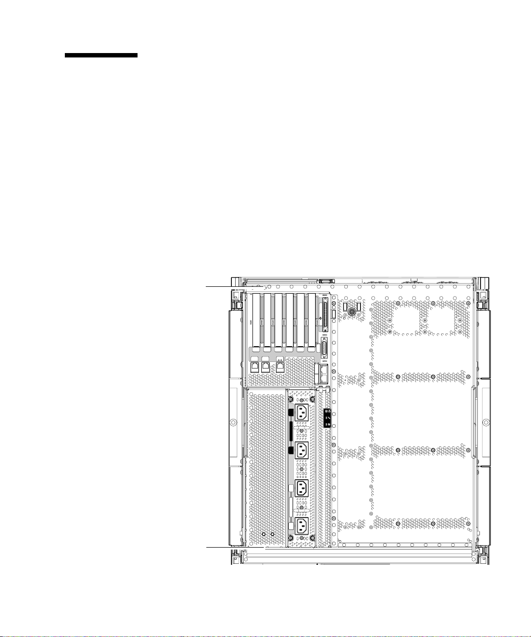
Threaded holes for attaching the CMA are provided on the rear of the system
(
FIGURE 1-15).
Upper
bracket holes
SCSI3
PCI 3
PCI 1
PCI 2
PCI 4
PCI 0
33MHz
33MHz
SSC1 SSC1
BB
A
Serial A Serial B
33MHz
PCI 5
33MHz
33MHz
66MHz
ALARMS
Link
Active
NET
0
GBit
Link
Active
NET
1
GBit
Lower
bracket holes
FIGURE 1-15 Bracket Mounting Holes
AC
3
SOURCE A
SOURCE B
AC
2
AC
1
SOURCE A
AC
0
Chapter 1 Physical Installation 1-21
Page 50

1.4.1 Installing the CMA–Lite
1. Secure the pivot at the end of the upper arm to the top rear of the system, using
the two captive screws (
2. Secure the center pivot point of the CMA to the inside rear of the left hand rail
assembly, using the two captive screws.
3. Secure the pivot at the end of the lower arm to the bottom rear of the system,
using the two captive screws.
FIGURE 1-16).
Captive
screws (2)
CMA-LIte
FIGURE 1-16 CMA–Lite Cable Management Arm
1-22 Sun Fire E2900 Systems Installation Guide • May 2006
Captive
screws (2)
Captive
screws (2)
Page 51

1.4.2 Installing the CMA–800.
t
t
To install a CMA-800 proceed as follows:
1. Refer to
CMA parts.
FIGURE 1-17, throughout the following procedures for identification of
Hinge pin
Upper pivot
bracket
Upper CMA arm
Guide bar
Hinge pin
Lower pivot
bracket
Guide slo
Left hand
T-bracket
Lower CMA arm
FIGURE 1-17 Upper/Lower CMA Arms and Left Hand/Right Hand T-Brackets
Right hand
T-bracket
Guide bar
Chapter 1 Physical Installation 1-23
Guide slo
Page 52

Note – In the following procedure all left-hand and right-hand orientation is as
viewed from the rear of the system chassis.
2. Remove the hinge pin securing the pivot bracket to the upper CMA arm, which
will facilitate attaching the bracket to the system chassis.
3. Secure the pivot bracket to the upper left hand side of the system chassis using
the two captive screws. See FIGURE 1-18 and FIGURE 1-19.
After attaching the pivot bracket to the chassis, use the hinge pin removed
previously to secure it to the upper CMA arm.
Upper pivot bracket
mounting holes
Upper pivot
bracket
Lower pivot
bracket
Lower pivot bracket
mounting holes
(hidden)
FIGURE 1-18 Upper/Lower Pivot Bracket Mounting Holes
1-24 Sun Fire E2900 Systems Installation Guide • May 2006
Page 53

Hinge pin
Upper pivot bracket
Upper CMA arm
FIGURE 1-19 Attachment of Upper CMA Arm and Pivot Bracket
Chapter 1 Physical Installation 1-25
Page 54

4. Remove the hinge pin securing the pivot bracket to the lower CMA arm, which
will facilitate attaching the bracket to the system chassis.
5. Secure the pivot bracket to the lower left hand of the system chassis using the two
captive screws, see
FIGURE 1-18 and FIGURE 1-20.
6. After attaching the bracket to the chassis, secure the lower CMA arm to the
bracket using the hinge pin removed previously.
Hinge pin
Lower pivot bracket
Lower CMA arm
FIGURE 1-20 Attachment of Lower CMA Arm and Pivot Bracket
1-26 Sun Fire E2900 Systems Installation Guide • May 2006
Page 55

7. Secure the left hand T-bracket to the left hand slide rail using two captive screws,
FIGURE 1-21.
Slide rail
Left hand T-bracket
FIGURE 1-21 Attaching Left Hand T-Bracket
Chapter 1 Physical Installation 1-27
Page 56

8. Secure the right hand T-bracket to the right hand slide rail using two captive
screws,
FIGURE 1-22.
Slide rail
Right hand T-bracket
FIGURE 1-22 Attachment of Right-Hand T-Bracket
1-28 Sun Fire E2900 Systems Installation Guide • May 2006
Page 57

9. Secure the upper CMA arm to left hand T-bracket using a single hinge pin
FIGURE 1-23.
Hinge pin
Guide bars
Hinge pin
Left hand T-bracket
Right hand T-bracket
FIGURE 1-23 Attachment of Upper/Lower CMA Arms to T-Bracket
10. Secure the lower CMA arm to the left hand T-bracket using a single hinge pin,.
FIGURE 1-23.
11. Route the cabling through the cable channels as desired and then secure both the
upper and lower CMA arms by inserting the guide bars of each arm into the slots
provided on the right hand T-bracket.
Chapter 1 Physical Installation 1-29
Page 58

1.5 Connecting Sun Fire V1280/Netra 1280 Power Cables
Caution – The Sun Fire V1280/Netra 1280 system is designed to work with power
systems having a grounded neutral conductor. Do not connect the equipment into
any other type of power system. Contact your facilities manager or a qualified
electrician to determine what type of power is supplied to your building.
Caution – Your Sun product is shipped with grounding-type (three-wire) power
cords. Always connect the cords into grounded power outlets.
Caution – The socket outlets must be installed near the equipment and easily
accessible.
1. Turn the system power switch to the Standby position.
Caution – The On/Standby power switch does not isolate the equipment. The AC
power cords are the primary means of disconnection for this product.
2. Turn the cabinet power off (in a powered cabinet).
Refer to the installation guide that came with the cabinet.
3. Label both ends of the power cords.
Two cords should be labeled Source A and two should be labeled Source B.
4. Connect the power cables to the system.
a. Connect the Source A power cords to AC0 and AC1 on the system and the
Source B power cords to AC2 and AC3 on the system.
b. Run the power cords through the CMA and secure them with tie wraps.
Make sure the CMA can extend and retract without dislodging the power cords.
1-30 Sun Fire E2900 Systems Installation Guide • May 2006
Page 59

Note – Step 3 and Step 4 will already be completed for systems that come pre
installed in a Sun Rack 900 cabinet.
5. Connect the system to the power source.
Note – It is the installer’s responsibility to ensure that the cabinet has sufficient
electrical power and redundancy to handle the required installation.
● If mounted in an unpowered cabinet:
a. Connect power cords from Source A on the system to the customer-supplied
power source A circuit breakers.
b. Connect power cords from Source B on the system to the customer-supplied
power source B circuit breakers.
● If mounted in a powered cabinet:
a. Connect power cords from Source A on the cabinet to the customer-supplied
power source A circuit breakers and Source B on the cabinet to the customersupplied power source B circuit breakers.
Refer to the installation guide that came with the cabinet for instructions on
cabinet power cabling.
b. Connect power cords from Source A on the cabinet to Source A on the system
and Source B on the cabinet to the Source B on the system.
Refer to the installation guide that came with the cabinet for instructions on
cabinet power cabling.
Chapter 1 Physical Installation 1-31
Page 60

1.6 Connecting Consoles to the System Controller
This section contains the following topics:
■ Section 1.6.1, “Connecting the Initial Administrative Console” on page 1-33
■ Section 1.6.2, “Connecting the Administrative Console” on page 1-35
The system controller (SC) is responsible for providing the Lights-Out Management
(LOM) functions, which include power on sequencing, executing module power-on
self-tests (POST), environmental monitoring, fault indication and alarms.
The LOM command-line interface and the Solaris/OpenBoot™ PROM console are
accessed by connecting an administrative console to either serial port A or the
10/100 LOM Ethernet port. The administrative console can be any external input
device (laptop computer or workstation) connected to either of these ports.
Serial port A is used to connect directly to an ASCII terminal or a network terminal
server (NTS) using a command-line interface. This port is used for the initial
administrative console. It is used to modify the default system controller settings
(usually so that the 10/100 LOM Ethernet port can be used as an administrative
console). The configuration of Serial port A cannot be changed. See Appendix A for
details on the Serial ports.
The 10/100 LOM Ethernet port is used to connect the system controller to the
network. This port is preconfigured as follows:
■ System controller configured to be on a network
■ System controller Ethernet configured for Dynamic Host Configuration Protocol
(DHCP)
■ No pre-configured system controller Ethernet IP address, Gateway, Domain name
system (DNS) domain, DNS servers
1-32 Sun Fire E2900 Systems Installation Guide • May 2006
Page 61

1.6.1 Connecting the Initial Administrative Console
For the initial configuration, connect Serial A port to the serial port on any of the
following devices:
■ ASCII terminal
■ Sun workstation
■ Terminal server (or patch panel connected to a terminal server)
Note – If the IP address assigned to the 10/100 LOM Ethernet port by DHCP is
known, the 10/100 LOM Ethernet port can be accessed without the Serial A port.
1. Connect the administrative console to the Serial A port.
The Serial A port is a DTE (data terminal equipment) port. An adapter, crossover
cable or null modem cable is required to connect the Serial A port to another DTE
port. For Serial A port connector pinouts and adaptor information, see Section A.4,
“LOM Serial Ports” on page A-6.
2. Turn the customer-supplied circuit breakers power switch to the On position.
3. Turn the system power switch to the On position.
Refer to the Sun Fire Entry-level Midrange System Administration Guide.
4. Set up the administrative console.
Refer to the Sun Fire Entry-level Midrange System Administration Guide.
Chapter 1 Physical Installation 1-33
Page 62

I/O Assembly
68-pin SCSI port
Alarms port
Serial A port
10/100 LOM
Ethernet port
Net0/Net1
Ethernet port
PCI 1
PCI 2
PCI 0
33MHz
33MHz
SSC1 SSC1
BB
A
Serial A Serial B
SCSI3
PCI 3
PCI 4
PCI 5
33MHz
33MHz
33MHz
66MHz
ALARMS
Link
Active
NET
0
GBit
Link
Active
NET
1
GBit
AC
3
SOURCE A
SOURCE B
AC
2
AC
1
SOURCE A
AC
0
FIGURE 1-24 System Controller and I/O Assembly Locations
1-34 Sun Fire E2900 Systems Installation Guide • May 2006
Page 63

1.6.2 Connecting the Administrative Console
Once the initial configuration is complete, you can perform system administration
tasks directly or over the network using the 10/100 LOM Ethernet port.
Note – Communication on the Serial A port is possible but is subject to interruption
by the LOM device. Refer to the Sun Fire Entry-level Midrange System Administration
Guide.
1. Connect the 10/100 LOM Ethernet port to the chosen administrative console (local
hub, router, or switch).
For 10/100 LOM Ethernet
Port” on page A-8.
2. Set up the chosen administrative console.
Refer to the Sun Fire Entry-level Midrange System Administration Guide.
port connector information, see “10/100 LOM Ethernet
1.7 Connecting the I/O Assemblies
The I/O assemblies provide network interface and peripheral access to the system
domains.
1. Connect one end of the I/O Ethernet cable to the Net0/Net1 Ethernet port
(
FIGURE 1-24).
2. Connect the other end of the I/O Ethernet cable to the hub, workstation, or
peripheral.
1.8 Powering On the System
1. Turn the power switch to the On position.
2. Power on the system.
Refer to the Sun Fire Entry-level Midrange System Administration Guide.
Chapter 1 Physical Installation 1-35
Page 64

1.9 Powering Off the System
1. Notify users that the system is going down.
2. Back up the system files and data to tape, if necessary.
3. Halt the Solaris™ operating system.
Refer to the Sun Fire Entry-level Midrange System Administration Guide.
4. Wait for the system-halted message and the boot monitor prompt.
5. Turn off each external drive and expansion cabinet (as applicable).
6. Turn the power switch to the Standby position.
Caution – The On/Standby power switch does not isolate the equipment. Turning
off the power switch on the customer-supplied circuit breakers is required to isolate
the equipment.
1.10 Installing Additional Hardware
Do not install additional hardware until the initial factory configuration has been
completely installed, the system has been powered on, and POST has been
completed successfully. This makes it easier to diagnose conflicts that might be
caused by additional installations.
Caution – To avoid damaging boards when installing CPU/Memory boards, refer
to the Sun Fire V1280/Netra 1280 Systems Service Manual for instructions.
Caution – During initial installation, turn off the power at the circuit breakers
before removing or replacing system hardware. Refer to the installation guide of the
additional hardware for any additional instructions.
For optimum performance, use only I/O cards and associated drivers that are
qualified by Sun Microsystems for use on the Sun Fire V1280/Netra 1280 systems. It
is possible for interactions to occur between cards and drivers on a specific bus that
might lead to potential system panics or other negative outcomes if the card/driver
1-36 Sun Fire E2900 Systems Installation Guide • May 2006
Page 65

solution is not qualified by Sun Microsystems.
For an updated listing of qualified I/O cards and configurations for the system,
contact your Sun authorized sales representative or your service provider. For
additional information refer to:
http://www.sun.com/io
1.11 Installing Additional Peripheral Devices
When you add additional storage devices, refer to the Rackmount Placement Matrix,at
http://docs.sun.com, for the mounting hole numbers of the mounting screws
for Sun Microsystems disk arrays, other storage trays, and devices.
Unless otherwise specified in the Rackmount Placement Matrix, mount the heaviest
subassemblies at the lowest available opening to minimize the effects of a top-heavy
system in the event of an earthquake.
Refer to the installation guide for the peripheral device for additional instructions.
Chapter 1 Physical Installation 1-37
Page 66

1-38 Sun Fire E2900 Systems Installation Guide • May 2006
Page 67

APPENDIX
A
External Connections
This appendix describes the cables and connectors that should be available in order
for the installation to be completed. Sun Fire V1280/Netra 1280 systems have the
following slots, connectors, and ports on the rear of the system:
■ Six I/O slots
■ SCSI connector
■ Alarms port
■ LOM Serial ports (serial system controller ports, one reserved)
■ 10/100 LOM Ethernet port (system controller Ethernet port)
■ Net0/Net1 Ethernet port (Two-gigabit Ethernet RJ-45 ports)
I/O0 - I/O5
SCSI connector
Alarms port
LOM Serial ports
10/100 LOM
Ethernet port
Net0/Net1
Ethernet port
FIGURE A-1 External I/O Connections—Sun Fire V1280/Netra 1280 Systems (Rear View)
PCI 1
PCI 2
PCI 0
33MHz
33MHz
SSC1 SSC1
BB
A
Serial A Serial B
SCSI3
PCI 3
PCI 4
PCI 5
33MHz
33MHz
33MHz
66MHz
ALARMS
Link
Active
NET
0
GBit
Link
Active
NET
1
GBit
AC
3
OURCE A
OURCE B
A-1
Page 68

A.1 I/O Slots
There are currently two versions of IB_SSC assemblies, PCI and PCI+. Consult your
Sun representative for cards supported by your version of the IB_SSC assembly.
Note – Mixing PCI, PCI+ and PCI-X cards within an IB6 leaf (two slots) is not
recommended since leaf slots run at the lowest speed and the lowest mode for a
given set of cards within a leaf. For example, if a 66 MHz PCI card is in slot 0 and a
100 MHz PCI-X card is in slot 1, then both leaf slots will run at the lower 66 MHz
PCI speed. IB6 leafs are comprised of paired slots 0 and 1, 2 and 3, and 4 and 5.
A.1.1 PCI IB_SSC Assemblies
PCI IB_SSC assemblies provide six I/O slots labeled 0 through 5. When viewing the
rear of the system, slot 0 is on the left and slot 5 is on the right. Slot 0 supports 66
MHz, slots 1-5 support 33 MHz with 5V signaling. The I/O slots are not hot
swappable. All slots are half length.
A.1.2 PCI+ IB_SSC Assemblies
PCI+ IB_SSC assemblies provide six I/O slots labeled 0 through 5. When viewing
the rear of the system, slot 0 is on the left and slot 5 is on the right. All six slots
support 33/66 MHz. The I/O slots are not hot swappable, all slots are half length
and 5V signaling is not supported.
A.1.3 PCI-X IB_SSC Assemblies
PCI- X IB_SSC assemblies provide six I/O slots labeled 0 through 5. When viewing
the rear of the system, slot 0 is on the left and slot 5 is on the right. All six slots
support 33/66/100 MHz. The I/O slots are not hot swappable, all slots are half
length with 3.3V signaling.
A-2 Sun Fire E2900 Systems Installation Guide • May 2006
Page 69

A.2 SCSI Connector
The SCSI Connector is a 68-pin SCSI connector (FIGURE A-2). TABLE A-1 lists the
pinout information.
SCSI3
FIGURE A-2 68-Pin SCSI Connector
TABLE A-1 68-Pin SCSI Connector Pinout
Pin No. Signal Name Type Pin No. Signal Name Type Pin No. Signal Name Type
34
68
1 +DB(12) I/O 24 +ACK I/O 47 –DB(7) I/O
2 +DB(13) I/O 25 +RST I/O 48 -DB(P0) I/O
3 +DB(14) I/O 26 +MSG I/O 49 Ground GND
4 +DB(15) I/O 27 +SEL I/O 50 Ground GND
5 +DB(P1) I/O 28 +C/D I/O 51 Termpwr POWER
6 +DB(0) I/O 29 +REQ I/O 52 Termpwr POWER
7 +DB(1) I/O 30 +I/O I/O 53 Reserved NA
8 +DB(2) I/O 31 +DB(8) I/O 54 Ground GND
9 +DB(3) I/O 32 +DB(9) I/O 55 –ATN I/O
10 +DB(4) I/O 33 +DB(10) I/O 56 Ground GND
11 +DB(5) I/O 34 +DB(11) I/O 57 –BSY I/O
12 +DB(6) I/O 35 –DB(12) I/O 58 –ACK I/O
13 +DB(7) I/O 36 –DB(13) I/O 59 –RST I/O
14 +DB(P0) I/O 37 –DB(14) I/O 60 –MSG I/O
15 Ground GND 38 –DB(15) I/O 61 –SEL I/O
16 Diffsens ANAL 39 –DB(P1) I/O 62 –C/D I/O
17 Termpwr POWER 40 –DB(0) I/O 63 –REQ I/O
1
35
Appendix A External Connections A-3
Page 70

TABLE A-2 68-Pin SCSI Connector Pinout (continued)
Pin No. Signal Name Type Pin No. Signal Name Type Pin No. Signal Name Type
18 Termpwr POWER 41 –DB(1) I/O 64 –I/O I/O
19 Reserved NA 42 –DB(2) I/O 65 –DB(8) I/O
20 Ground GND 43 –DB(3) I/O 66 –DB(9) I/O
21 +ATN I/O 44 –DB(4) I/O 67 –DB(10) I/O
22 Ground GND 45 –DB(5) I/O 68 –DB(11) I/O
23 +BSY I/O 46 –DB(6) I/O
A.2.1 SCSI Implementation
For PCI IB_SSC assemblies the embedded SCSI subsystem is:
■ SCSI Fast-160 (UltraSCSI) low-voltage differential parallel interface
■ 16-bit SCSI bus
■ 160-MBps data transfer rate
Maximum cable length (terminator to terminator) support is 82 ft. (25 meter) for
low-voltage differential, point-to-point interconnect.
For PCI+ and PCI-X IB_SSC assemblies the embedded SCSI subsystem is:
■ SCSI Ultra-320 (UltraSCSI) low-voltage differential parallel interface
■ 16-bit SCSI bus
■ 320-MBps data transfer rate
Maximum cable length support is 33 ft. (10 meters).
A-4 Sun Fire E2900 Systems Installation Guide • May 2006
Page 71

A.3 Alarms Port
The alarms service port is a male DB-15 (FIGURE A-3). TABLE A-3 lists the pinout
information.
9
FIGURE A-3 DB-15 (Male) Alarms Service Port Connector
TABLE A-3 Alarms Service Port Connector Pinout
Pin Signal Name Description State
1 Not connected
2 Not connected
3 Not connected
4 Not connected
5 SYSTEM_NO UNIX Running Normally open
6 SYSTEM_NC UNIX Running Normally closed
7 SYSTEM_COM UNIX Running Common
8 ALARM1_NO Alarm1 Normally open
9 ALARM1_NC Alarm1 Normally closed
10 ALARM1_COM Alarm1 Common
11 ALARM2_NO Alarm2 Normally open
12 ALARM2_NC Alarm2 Normally closed
13 ALARM2_COM Alarm2 Common
14 Not connected
15 Not connected
81
15
ALARMS
Appendix A External Connections A-5
Page 72

A.4 LOM Serial Ports
LOM Serial ports A and B use RJ-45 connectors (FIGURE A-4). These ports are also
known as the system controller serial ports.
1818
Serial A
FIGURE A-4 RJ-45 Serial Connectors
TABLE A-4 RJ-45 Serial Connector Pinout
Pin Signal
1RTS
2 DTR
3 TXD
4 Signal Ground
Serial B
TABLE A-4 lists the pinout information.
5 Signal Ground
6 RXD
7 DSR
8 CTS
Note – Serial port B is reserved.
A-6 Sun Fire E2900 Systems Installation Guide • May 2006
Page 73

TABLE A-5 lists the settings needed to use the serial connection. The configuration of
this port cannot be changed. Be sure to check the manufacturer’s documentation for
your specific terminal server. Communication on Serial A is subject to interruption
by the LOM device. Refer to the Sun Fire Entry-level Midrange System Administration
Guide.
TABLE A-5 Default Settings for Connecting to Serial A
Parameter Setting
Connector Serial A
Rate 9600 baud
Parity No
Stop bits 1
Data bits 8
A.4.1 Using a DB-25 Adapter for Your Serial Link
To connect from a VT100 terminal, use either the DB-25 (25-Pin DSUB male to 8-POS
RJ-45 female) adapter supplied with your system (part number 530-2889) or an
alternative adapter that performs the same pin interconnections. The Sun-supplied
DB-25 adapter enables you to connect to any Sun system.
interconnections the DB-25 adapter performs.
TABLE A-6 Pin Interconnections Performed by the Sun DB-25 Adapter
TABLE A-6 lists the pin
Serial Port (RJ-45 Connector) Pin 25-Pin Connector Pins
Pin 1 (RTS) Pin 5 (CTS)
Pin 2 (DTR) Pin 6 (DSR)
Pin 3 (TXD) Pin 3 (RXD)
Pin 4 (Signal Ground) Pin 7 (Signal Ground)
Pin 5 (Signal Ground) Pin 7 (Signal Ground)
Pin 6 (RXD) Pin 2 (TXD)
Pin 7 (DSR) Pin 20 (DTR)
Pin 8 (CTS) Pin 4 (RTS)
Appendix A External Connections A-7
Page 74

A.4.2 Using a DB-9 Adapter for Your Serial Link
Connect serial A to a DB-9 (9-pin) adapter to connect to a terminal that has a 9-pin
serial connector.
TABLE A-7 Pin Interconnections Performed by a DB-9 (9-pin) Adapter
Serial Port (RJ-45 Connector) Pin 9-Pin Connector
Pin 1 (RTS) Pin 8 (CTS)
Pin 2 (DTR) Pin 6 (DSR)
Pin 3 (TXD) Pin 2 (RXD)
Pin 4 (Signal Ground) Pin5 (Signal Ground)
Pin 5 (Signal Ground) Pin 5 (Signal Ground)
Pin 6 (RXD) Pin 3 (TXD)
Pin 7 (DSR) Pin 4 (DTR)
Pin 8 (CTS) Pin 7 (RTS)
A.4.2.1 Connecting to a Male 9-Pin D-Type Serial Port
1. Connect one end of the RJ-45 patch cable to Serial A and the other end to the DB25 adapter (supplied with the system).
TABLE A-7 lists the pin interconnections.
2. Connect the DB-25 adapter to an adapter that has one 25-way female connector
and one 9-way D-type female connector.
Sun does not supply a 25x9-way D-type female-to-female adapter.
3. Connect the male end of a 9-pin serial cable to the 25x9-way D-type female-tofemale adapter and the other end to the 9-pin serial port on the administrative
console.
A-8 Sun Fire E2900 Systems Installation Guide • May 2006
Page 75

A.5 10/100 LOM Ethernet Port
The 10/100 LOM Ethernet port is an RJ-45 twisted-pair Ethernet (TPE) connector
(
FIGURE A-5). This port is also known as the system controller Ethernet port.
TABLE A-8 lists the pinout information.
SSC1
18
FIGURE A-5 RJ-45 TPE Socket
TABLE A-8 Twisted-pair Ethernet Connector Pinout
Pin Description Pin Description
1 TXD+ 5 Common mode termination
2 TXD– 6 RXD–
3 RXD+ 7 Common mode termination
4 Common mode termination 8 Common mode termination
A.5.1 Twisted-Pair Ethernet Cable-Type Connectivity
The following types of TPE cables can be connected to the 8-pin TPE connector:
■ For 10BASE-T applications, shielded twisted-pair (STP) cable:
■ Category 3 (STP-3, voice grade)
■ Category 4 (STP-4)
■ Category 5 (STP-5, data grade)
■ For 100BASE-T applications, shielded twisted-pair category 5 (STP-5, data grade)
cable.
TABLE A-9 TPE STP-5 Cable Lengths
Cable Type Application(s)
Maximum Length
(Metric)
Shielded twisted pair category 5 (STP-5, data grade) 10BASE-T 1000 m 3282 ft
Shielded twisted pair category 5 (STP-5, data grade) 100BASE-T 100 m 327 ft
Appendix A External Connections A-9
Maximum Length
(Imperial)
Page 76

A.6 Net0/Net1 Ethernet Ports
The Net0/Net1 Ethernet ports are shielded RJ-45 connectors (FIGURE A-6). The
Net0/Net1 Ethernet ports are also known as the gigabit Ethernet RJ-45 ports.
TABLE A-10 lists the pinout information.
1
NET 0
8
1
NET 1
8
FIGURE A-6 RJ-45 Gigabit Ethernet Connectors
TABLE A-10 RJ-45 Gigabit Ethernet Connector Pinout
Pin Signal Name Pin Signal Name
1 TRD0_H 5 TRD2_L
2 TRD0_L 6 TRD1_L
3 TRD1_H 7 TRD3_H
4 TRD2_H 8 TRD3_L
A-10 Sun Fire E2900 Systems Installation Guide • May 2006
 Loading...