

Page 1

Sun Fire
™
B1600
Blade System Chassis
Hardware Installation Guide
Sun Microsystems, Inc.
4150 Network Circle
Santa Clara, CA 95054 U.S.A.
650-960-1300
Part No. 817-3430-10
August 2003, Revision A
Send comments about this document to: docfeedback@sun.com
Page 2

Copyright 2003Sun Microsystems,Inc., 4150Network Circle, SantaClara, California95054, U.S.A.All rightsreserved.
Sun Microsystems,Inc. hasintellectual property rightsrelating totechnology embodiedin theproduct that is described inthis document.In
particular,and withoutlimitation, theseintellectual property rightsmay includeone ormore ofthe U.S.patents listedat
http://www.sun.com/patents andone ormore additionalpatents orpending patentapplications inthe U.S.and inother countries.
This documentand theproduct towhich itpertains are distributedunder licensesrestricting theiruse, copying,distribution, and
decompilation. Nopart ofthe productor ofthis documentmay bereproducedin anyform byany meanswithout priorwritten authorizationof
Sun andits licensors,if any.
Third-party software, includingfont technology,is copyrightedand licensedfrom Sun suppliers.
Parts ofthe productmay bederived from BerkeleyBSD systems,licensed fromthe Universityof California.UNIX isa registered trademarkin
the U.S.and inother countries,exclusively licensedthrough X/OpenCompany, Ltd.
Sun, Sun Microsystems,the Sunlogo, AnswerBook2,docs.sun.com, Netra,Netra ft,Sun Fire, andSolaris aretrademarks orregistered
trademarks ofSun Microsystems,Inc. inthe U.S.and inother countries.
All SPARCtrademarks areused underlicense andare trademarks or registered trademarksof SPARCInternational, Inc.in theU.S. andin other
countries. Productsbearing SPARCtrademarks are basedupon anarchitecture developed by Sun Microsystems,Inc. TheEnergy Starlogo isa
registered trademark of EPA.
The OPENLOOK andSun™ GraphicalUser Interfacewas developedby SunMicrosystems, Inc.for itsusers andlicensees. Sun acknowledges
the pioneeringefforts ofXerox in researchingand developingthe conceptof visualor graphicaluser interfacesfor thecomputer industry.Sun
holds anon-exclusive licensefrom Xerox tothe XeroxGraphical UserInterface, whichlicense alsocovers Sun’slicensees whoimplement OPEN
LOOK GUIsand otherwisecomply withSun’s writtenlicense agreements.
Use, duplication,or disclosure bythe U.S.Government issubject to restrictionsset forthin theSun Microsystems, Inc.license agreementsand as
provided inDFARS 227.7202-1(a)and 227.7202-3(a)(1995), DFARS 252.227-7013(c)(1)(ii) (Oct. 1998), FAR 12.212(a)(1995), FAR52.227-19, or
FAR52.227-14 (ALTIII), asapplicable.
DOCUMENTATION IS PROVIDED "AS IS" AND ALL EXPRESS OR IMPLIED CONDITIONS, REPRESENTATIONS AND WARRANTIES,
INCLUDING ANYIMPLIED WARRANTY OFMERCHANTABILITY, FITNESSFOR A PARTICULAR PURPOSEOR NON-INFRINGEMENT,
ARE DISCLAIMED, EXCEPT TO THE EXTENT THAT SUCH DISCLAIMERS ARE HELD TO BE LEGALLY INVALID.
Copyright 2003Sun Microsystems,Inc., 4150Network Circle, SantaClara, California95054, Etats-Unis.Tous droitsréservés.
Sun Microsystems,Inc. ales droits depropriété intellectuelsrelatants à la technologie incorporée dans leproduit quiest décritdans ce
document. Enparticulier,et sansla limitation,ces droits depropriété intellectuelspeuvent inclure unou plusdes brevetsaméricains énumérés
à http://www.sun.com/patents et unou lesbrevets plus supplémentairesou lesapplications debrevet enattente dansles Etats-Uniset dans
les autrespays.
Ce produitou documentest protégé parun copyrightet distribuéavec deslicences quien restreignent l’utilisation,la copie,la distribution,et la
décompilation. Aucunepartie dece produitou documentne peutêtre reproduite sousaucune forme,parquelque moyen que ce soit, sans
l’autorisation préalableet écritede Sunet deses bailleursde licence,s’il yena.
Le logicieldétenu pardes tiers,et quicomprend latechnologie relative auxpolices decaractères, estprotégépar uncopyright etlicencié pardes
fournisseurs deSun.
Des partiesde ceproduit pourront êtredérivées dessystèmes BerkeleyBSD licenciéspar l’Universitéde Californie.UNIX estune marque
déposée auxEtats-Unis etdans d’autrespays etlicenciée exclusivementpar X/OpenCompany, Ltd.
Sun, SunMicrosystems, lelogo Sun,AnswerBook2, docs.sun.com,Netra, Netraft, SunFire, et Solaris sont desmarques defabrique oudes
marques déposéesde SunMicrosystems, Inc. aux Etats-Unis et dans d’autrespays.
Toutes lesmarques SPARC sont utilisées sous licence et sont des marques defabrique oudes marquesdéposées deSPARC International,Inc.
aux Etats-Uniset dansd’autres pays.Les produits protantles marques SPARC sont baséssur unearchitecturedéveloppée parSun
Microsystems, Inc.
L’interfaced’utilisation graphiqueOPEN LOOKet Sun™a étédéveloppée parSun Microsystems, Inc.pour sesutilisateurs etlicenciés. Sun
reconnaît lesefforts de pionniers de Xeroxpour larecherche et le développment du concept des interfaces d’utilisation visuelle ou graphique
pour l’industriede l’informatique.Sun détientune licensenon exclusivedo Xeroxsur l’interfaced’utilisation graphiqueXerox, cette licence
couvrant égalementles licenciéesde Sunqui mettenten placel’interface d’utilisation graphiqueOPEN LOOKet quien outrese conforment
aux licencesécrites deSun.
LA DOCUMENTATION EST FOURNIE "EN L’ÉTAT" ET TOUTES AUTRES CONDITIONS, DECLARATIONS ET GARANTIES EXPRESSES
OU TACITES SONT FORMELLEMENTEXCLUES, DANSLA MESUREAUTORISEE PARLA LOIAPPLICABLE, YCOMPRIS NOTAMMENT
TOUTE GARANTIE IMPLICITE RELATIVE A LA QUALITE MARCHANDE, A L’APTITUDE A UNE UTILISATION PARTICULIERE OU A
L’ABSENCE DE CONTREFAÇON.
Please
Recycle
Page 3

Contents
1. Preparing for the Installation 1–1
1.1 Checklist of Rackmounting and Setup Tasks 1–2
1.2 Contents of the Ship Kit 1–3
1.3 Tools and Equipment Needed 1–4
1.4 System Chassis Dimensions 1–4
1.5 Site Preparation 1–8
1.5.1 System Cooling Requirements 1–8
1.5.1.1 General Environmental Parameters 1–8
1.5.1.2 Airflow Requirements 1–11
1.5.1.3 Estimating the Heat Dissipation 1–11
1.5.2 Operating Power Limits and Ranges 1–12
1.5.3 Estimating Power Consumption 1–12
2. Rack Options and Placement 2–1
2.1 Rack Options 2–1
2.2 Service Access 2–2
2.3 Rack and Floor Loading 2–3
2.4 Rack and Cabinet Safety 2–3
3. Installing the System Chassis In a Rack or Cabinet 3–1
Contents iii
Page 4

3.1 Installing the System Chassis In a
Four-Post Rack or Cabinet 3–1
3.1.1 Contents of the Four-Post Rackmount Kit 3–2
3.1.2 Using the Rack Buddy 3–2
3.1.3 Attaching the Brackets to the Four-Post Rack 3–3
3.1.4 Installing the System Chassis In the Four-Post Rack or Cabinet
3–6
3.2 Installing the System In a Two-Post Rack 3–11
3.2.1 Contents of the Two-Post Rackmount Kit 3–11
3.2.2 Installing the System Chassis In a Two-Post Rack 3–12
3.3 What to Do Next 3–16
4. Removing and Installing Modules 4–1
4.1 Removing and Installing Blades or Filler Panels 4–2
4.1.1 Removing Blades or Filler Panels 4–3
4.1.2 Installing a Blade or Filler Panel 4–6
4.2 Removing and Installing a PSU 4–9
4.2.1 Removing a PSU 4–10
4.2.2 Inserting a PSU 4–12
4.3 Removing and Installing a Switch and System Controller (SSC) 4–15
4.3.1 Chassis Supplied With Only One SSC 4–15
4.3.2 Removing the SSC 4–17
4.3.3 Installing the SSC 4–19
4.4 What to Do Next 4–22
5. Connecting and Managing Cables 5–1
5.1 Location of Ports and Power Inlets 5–2
5.2 Connecting the IEC Power Cords 5–3
5.3 Cable Requirements for 1000BASE-T and 10/100BASE-TX Connections
5–5
iv Sun Fire B1600 System Chassis Hardware Installation Guide • August 2003
Page 5

5.3.1 1000BASE-T Cable Requirements 5–5
5.3.1.1 Cable Testing for Existing Category 5 Cable 5–5
5.3.2 Cable Requirements for 10/100BASE-TX Devices 5–6
5.4 Attaching the Connector Cables 5–6
5.5 Connecting to the 10/100/1000BASE-T Data Network Ports 5–7
5.6 Connecting to the 10/100BASE-T Network Management Ports 5–10
5.7 Managing Cables for Multiple System Chassis 5–12
5.8 What to Do Next 5–13
6. Connecting the RS232 Serial Port to Different Devices 6–1
6.1 Serial Port Pin Numbers 6–3
6.2 Connecting to a Terminal Server 6–4
6.3 Connecting to a VT100 Terminal or a Sun Workstation 6–5
6.4 Connecting to a Terminal That Has a
9-pin Adapter 6–6
6.5 Connecting to a Modem 6–7
6.6 Connecting the Cable to the Serial Port 6–8
6.7 Setting up a Serial Link to the System Controller Using a Laptop 6–9
6.7.1 Connecting to a Laptop 6–9
6.7.1.1 Using Microsoft Windows HyperTerminal 6–11
6.8 What to Do Next 6–12
Contents v
Page 6

vi Sun Fire B1600 System Chassis Hardware Installation Guide • August 2003
Page 7

Figures
FIGURE 1-1 System Chassis Dimensions (Top View) 1–6
FIGURE 1-2 System Chassis Dimensions (Front View) 1–7
FIGURE 1-3 Temperature and Altitude Operating Ranges 1–9
FIGURE 1-4 Temperature and Relative Humidity Ranges 1–9
FIGURE 2-1 EIA/RETMA Mounting Hole Pattern Dimensions 2–2
FIGURE 3-1 Using the Rack Buddy 3–2
FIGURE 3-2 Sliding the Front Bracket Section Into the Back Bracket Section
(19-Inch, Four-Post Rack) 3–3
FIGURE 3-3 Connecting the Front and Back Four-Post Bracket Sections (19-Inch, Four-Post Rack) 3–4
FIGURE 3-4 Inserting the Rack Bracket Spacer 3–5
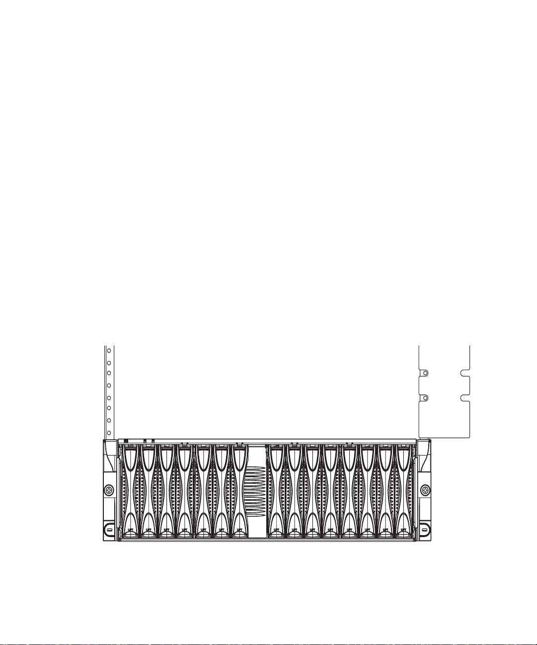
FIGURE 3-5 Removing the Module Retaining Pins 3–7
FIGURE 3-6 Aligning the System Chassis to the Brackets (19-Inch, Four-Post Rack) 3–8
FIGURE 3-7 Removing the Sacrificial Lifting Handle (19-Inch, Four-Post Rack) 3–9
FIGURE 3-8 Tightening the Captive Retaining Screws (19-Inch, Four-Post Rack) 3–10
FIGURE 3-9 Removing the Module Retaining Pins 3–12
FIGURE 3-10 Attaching the Two-Post Front Brackets to the System Chassis
(19-Inch, Two-Post Rack) 3–13
FIGURE 3-11 Attaching the Front of the System Chassis to the Rack
(19-Inch, Two-Post Rack) 3–14
FIGURE 3-12 Attaching the Back Brackets (19-Inch, Two-Post Rack) 3–15
FIGURE 4-1 B1600 System Chassis with Single-width and Double-width Blades 4–2
FIGURE 4-2 Disengaging the Blade Locking Mechanism 4–3
Figures vii
Page 8

FIGURE 4-3 Ejecting the Blade 4–4
FIGURE 4-4 Removing the Blade 4–5
FIGURE 4-5 Blade Locking Mechanism 4–6
FIGURE 4-6 Aligning and Inserting the Blade 4–7
FIGURE 4-7 Closing the Blade Lever Mechanism 4–8
FIGURE 4-8 PSU Ejector Lever 4–10
FIGURE 4-9 Removing the PSU From the System Chassis 4–11
FIGURE 4-10 Aligning the PSU 4–12
FIGURE 4-11 Sliding the PSU in the System Chassis 4–13
FIGURE 4-12 Closing the PSU Ejector Lever 4–14
FIGURE 4-13 Rear View of the Chassis Showing a Filler Module in Slot SSC1 4–16
FIGURE 4-14 SSC Ejector Lever 4–17
FIGURE 4-15 Removing the SSC From the System Chassis 4–18
FIGURE 4-16 Aligning the SSC Before Insertion 4–19
FIGURE 4-17 Inserting the SSC 4–20
FIGURE 4-18 Closing the SSC Ejector Lever 4–21
FIGURE 5-1 External Cable Ports (One SSC and PSU Shown) 5–2
FIGURE 5-2 Inserting the IEC Power Cords 5–3
FIGURE 5-3 Clipping on the Power Cord Retention Clip 5–4
FIGURE 5-4 The 10/100/1000BASE-T Data Network Ports 5–7
FIGURE 5-5 Attaching the Data Network Cables to the Network Ports 5–9
FIGURE 5-6 10/100BASE-T Network Management Ports 5–10
FIGURE 5-7 Attaching the Network Management Cables 5–11
FIGURE 5-8 Back Cable Management Rings 5–12
FIGURE 6-1 Serial Port Pin Numbers 6–3
FIGURE 6-2 Patch Panel Connections to a Terminal Server 6–4
FIGURE 6-3 Attaching the Serial Cables 6–8
FIGURE 6-4 Connecting the SSC to the Serial Port on a Laptop 6–10
viii Sun Fire B1600 System Chassis Hardware Installation Guide • August 2003
Page 9

Tables
TABLE 1-1 System Chassis Dimensions 1–4
TABLE 1-2 Operating and Storage Specifications 1–8
TABLE 1-3 Operating Power Limits and Ranges 1–12
TABLE 1-4 Power Consumption 1–12
TABLE 2-1 Mounting Hole Pattern Dimensions 2–2
TABLE 5-1 10/100/1000BASE-T Data Network Port Pinouts 5–8
TABLE 5-2 100BASE-T Network Management Port Pinouts 5–10
TABLE 6-1 Serial Port Pinouts 6–3
TABLE 6-2 Serial Port Pinouts to a Terminal Server 6–5
TABLE 6-3 Serial Port Pin Interconnections to a Sun DB-25 (25-pin) Adapter 6–6
TABLE 6-4 Serial Port Pin Interconnections to a DB-9 (9-pin) Adapter 6–7
TABLE 6-5 Default Settings for Connecting a Modem to the Serial Port 6–7
TABLE 6-6 Pin Inter-connections Required to be Performed by the 25x9-way D-type Female-to-Female
Adapter 6–10
Tables ix
Page 10

x Sun Fire B1600 System Chassis Hardware Installation Guide • August 2003
Page 11

Preface
This guide provides information about how to choose and prepare a location for a
Sun Fire B1600 blade system chassis, and details of how to install the system chassis
in a rack.
How This Book Is Organized
Chapter 1 describes the environmental requirements and airflow considerations for
the Sun Fire B1600 blade system chassis.
Chapter 2 explains the various rackmount options and requirements for the
system chassis.
Chapter 3 details how to install the system chassis into a rack.
Chapter 4 describes how to install a blade or filler panel in the system chassis. The
chapter also describes how to remove (and install) other components from the
system chassis.
Chapter 5 explains how to connect the IEC power supply cords and RJ-45 connectors
to the system chassis.
Chapter 6 explains how to connect the serial port to different devices.
xi
Page 12

Related Documentation
Application Title
Compliance and safety Sun Fire B1600 Blade System Chassis Compliance and Safety
Manual
Hardware installation
overview (foldout poster)
Hardware installation Sun Fire B1600 Blade System Chassis Hardware Installation
Software installation
overview (foldout poster)
Software setup Sun Fire B1600 Blade System Chassis Software Setup Guide
B100x and B200x server
blade installation and
setup
System chassis
administration and
component replacement
Switch administration Sun Fire B1600 Blade System Chassis Switch Administration
Late-breaking information Sun Fire B1600 Blade System Chassis Product Notes
Sun Fire B1600 Blade System Chassis Quick Start
Guide (this manual)
Sun Fire B1600 Blade System Chassis Software Setup Quick Start
Sun Fire B100x and B200x Server Blade Installation and Setup
Guide
Sun Fire B1600 Blade System Chassis Administration Guide
Guide
Accessing Sun Documentation
You can view or purchase a broad selection of Sun™ documentation, including
localized versions, at:
http://www.sun.com/documentation
You can also purchase printed copies of select Sun documentation from iUniverse,
the Sun documentation provider, at:
http://corppub.iuniverse.com/marketplace/sun/
xii Sun Fire B1600 System Chassis Hardware Installation Guide • August 2003
Page 13

Sun Welcomes Your Comments
Sun is interested in improving its documentation and welcomes your comments and
suggestions. You can email your comments to Sun at:
docfeedback@sun.com
Please include the part number (817-3430-10) of your document in the subject line of
your email.
Preface xiii
Page 14

xiv Sun Fire B1600 System Chassis Hardware Installation Guide • August 2003
Page 15

CHAPTER
1
Preparing for the Installation
This chapter provides the information you need to prepare for the installation of the
Sun Fire B1600 blade system chassis in the following sections:
■ Section 1.1, “Checklist of Rackmounting and Setup Tasks” on page 1-2
■ Section 1.2, “Contents of the Ship Kit” on page 1-3
■ Section 1.3, “Tools and Equipment Needed” on page 1-4
■ Section 1.4, “System Chassis Dimensions” on page 1-4
1-1
Page 16

1.1 Checklist of Rackmounting and Setup Tasks
1. Unpack the system chassis.
2. Check that you have the required parts for rackmounting.
See Section 1.2, “Contents of the Ship Kit” on page 1-3, Section 3.1.1, “Contents of
the Four-Post Rackmount Kit” on page 3-2,orSection 3.2.1, “Contents of the Two-
Post Rackmount Kit” on page 3-11.
3. Locate the rackmounting holes.
See Section 3.1.2, “Using the Rack Buddy” on page 3-2.
4. Install the rack brackets.
See Section 3.1.3, “Attaching the Brackets to the Four-Post Rack” on page 3-3 or
Section 3.2.2, “Installing the System Chassis In a Two-Post Rack” on page 3-12.
5. Install the system chassis in the rack or cabinet.
See Section 3.1, “Installing the System Chassis In a Four-Post Rack or Cabinet” on
page 3-1 or Section 3.2, “Installing the System In a Two-Post Rack” on page 3-11.
6. Install the blades, if applicable.
See Section 4.2, “Installing a Blade or Filler Panel” on page 4-5.
7. Remove and re-install the PSUs and SSCs if you want to check the serial numbers
or familiarize yourself with the installation and removal procedures.
See Section 4.3, “Removing and Installing a PSU” on page 4-8 and Section 4.4,
“Removing and Installing a Switch and System Controller (SSC)” on page 4-14.
8. Connect the power cords.
See Section 5.2, “Connecting the IEC Power Cords” on page 5-3.
9. Connect the management and data cables.
See Section 5.4, “Attaching the Connector Cables” on page 5-6.
10. Connect the serial port(s) to a serial device.
You can connect to both serial ports, if applicable. See Chapter 6 for details of how to
connect the system chassis to different devices.
11. Check that cables are managed correctly.
See Section 5.7, “Managing Cables for Multiple System Chassis” on page 5-12.
1-2 Sun Fire B1600 System Chassis Hardware Installation Guide • August 2003
Page 17

1.2 Contents of the Ship Kit
The Sun Fire B1600 blade system chassis is packaged in polyethylene foam cushions
for dynamic protection and is contained within a corrugated container with an
integrated wood pallet. The sealed corrugated container is attached to the wood
pallet at the base with cap nails. The assembly is banded to the wood pallet for
additional strength and protection.
The top panels of the container include instructions about how to unpack the
system. No special tools are required. One box contains the necessary
documentation and software, and the other box holds the rackmount hardware.
The modules shipped within the system chassis depend on the configuration
ordered.
The ship kit box accompanying the system contains some or all of the following
items:
■ Manuals:
■ Sun Fire B1600 Blade System Chassis Hardware Installation Guide
■ Sun Fire B1600 Blade System Chassis Compliance and Safety Manual (Multilingual)
■ Sun Fire B1600 Blade System Chassis Software Setup Guide
■ Sun Fire B1600 Blade System Chassis Software Quick Start Poster
■ Sun Fire B1600 Blade System Chassis Hardware Quick Start Poster
■ Sun Fire B100x and B200x Server Blade Installation and Setup Guide (supplied only
if the chassis contains B100x and/or B200x server blades)
■ CD: Sun Fire B1600 Platform Documentation, Drivers, and Installation CD
■ 19 Inch four post rackmount kit
■ Cables and connectors
Note – The operating system software kit must be ordered as a separate item. The
manuals and CD shipped with the system chassis are all that you need to install the
system chassis hardware.
Use the instructions in this guide and the Sun Fire B1600 Blade System Chassis
Product Notes (if present) to unship and mount the system.
Two people are required to lift a fully populated Sun Fire B1600 blade system chassis
into a four-post rack, and three people for a two-post rack. The system chassis
weighs approximately 45 kg (99lb) when fully equipped.
Chapter 1 Preparing for the Installation 1-3
Page 18

Do not remove any modules (blades, filler panels, PSUs, SSCs) from the system
chassis prior to rack installation as this may result in deformation of the chassis and
system chassis failure.
Ensure that doorways, corridors, and aisles are wide and high enough to
accommodate the system while you are maneuvering it into position.
1.3 Tools and Equipment Needed
You need the following equipment to install a Sun Fire B1600 blade system chassis:
■ A suitable host rack or cabinet.
■ The appropriate rackmount kit for the host rack or cabinet
■ Category 5 RJ-45 cabling. A maximum of 20 cables are required for a fully
populated system chassis
■ IEC power cabling. Two cables are required per system chassis
You will also need the following tools:
■ No. 2 Phillips screwdriver
■ The correct screwdriver for the rackmounting screws being attached to, and
supplied with, the host rack or cabinet
■ A cage nut insertion tool (only for racks or cabinets using caged nuts)
1.4 System Chassis Dimensions
The shipping dimensions of the Sun Fire B1600 blade system chassis are listed in
TABLE 1-1 and shown in FIGURE 1-1 and FIGURE 1-2.
TABLE 1-1 System Chassis Dimensions
Dimension US Measurement
Overall width 17.64 in. 448.0mm
Overall width, including sacrificial lifting handles 20.08 in. 510.0mm
Depth 26.81 in. 681.0mm
1-4 Sun Fire B1600 System Chassis Hardware Installation Guide • August 2003
Metric
Measurement
Page 19

TABLE 1-1 System Chassis Dimensions (Continued)
Dimension US Measurement
Metric
Measurement
Overall height 5.16 in. 131.0mm
Overall height, including sacrificial lifting handles 6.22 in. 158.0mm
Weight (fully populated) 99lb 45kg
Chapter 1 Preparing for the Installation 1-5
Page 20

26.81 in.
24 in.
(681.0mm) (609.6mm)
Orange sacrificial lifting handle
17.64 in.
(448.0mm)
20.08 in.
(510.0mm)
FIGURE 1-1 System Chassis Dimensions (Top View)
The system chassis is designed to fit in a 800mm rack. If you want to install the
system chassis in a rack less than 800mm deep, check the suitability of the rack
before you start the installation.
1-6 Sun Fire B1600 System Chassis Hardware Installation Guide • August 2003
Page 21

5.16 in.
6.22 in.
(131.0mm)
(158.0mm)
Orange sacrificial lifting handle
FIGURE 1-2 System Chassis Dimensions (Front View)
Chapter 1 Preparing for the Installation 1-7
Page 22

1.5 Site Preparation
This section contains information about the following system and site requirements
for the Sun Fire B1600 blade system chassis:
■ Section 1.5.1, “System Cooling Requirements” on page 1-8
■ Section 1.5.2, “Operating Power Limits and Ranges” on page 1-12
■ Section 1.5.3, “Estimating Power Consumption” on page 1-12
1.5.1 System Cooling Requirements
This section provides the general environmental parameters and airflow
requirements for the Sun Fire B1600 blade system chassis.
Note – The Sun Fire B1600 blade system chassis uses front-to-back forced air
cooling.
1.5.1.1 General Environmental Parameters
You can operate and store the system safely in the conditions detailed in TABLE 1-2,
FIGURE 1-3 and FIGURE 1-4.
TABLE 1-2 Operating and Storage Specifications
Specification Operating Storage
Ambient temperature 5˚C to 35˚C
maximum ambient
temperature is derated by 1˚C
per 500m altitude above 500m
Relative humidity 10% to 90% RH non-
condensing, 27˚C max wet
bulb
Altitude -400m up to 3000m -400m up to 12000m
1-8 Sun Fire B1600 System Chassis Hardware Installation Guide • August 2003
-40˚C to 65˚C
up to 93% RH noncondensing, 38˚C max wet
bulb
Page 23

35
Temperature, ˚C
5
-400
106
500
95
3000
70
Altitude, m
Pressure, kPa
FIGURE 1-3 Temperature and Altitude Operating Ranges
27˚C wet bulb temperature
90% RH
Moisture content
10% RH
5
35
Dry bulb temperature, ˚C
FIGURE 1-4 Temperature and Relative Humidity Ranges
Chapter 1 Preparing for the Installation 1-9
Page 24

Recommended Environment Parameters
Your environmental control system must provide intake air for the server which
complies with the limits specified in “General Environmental Parameters” on
page 1-8.
To avoid overheating, do not direct warmed air:
■ towards the front of the cabinet or rack
■ towards the server access panels
Note – When you receive your system, leave it in the shipping crate at its final
destination for 24 hours in the environment in which you will install it. This is to
prevent thermal shock and condensation.
The operating environmental limits in
TABLE 1-2 reflect what the systems have been
tested to, in order to meet all functional requirements. Operating computer
equipment in extremes of temperature or humidity increases the failure rate of
hardware components. To minimize the chance of component failure, use the server
within the optimal temperature and humidity ranges.
Ambient Temperature
An ambient temperature range of 21˚C to 23˚C is optimal for system reliability. At
22˚C it is easy to maintain safe relative humidity levels. Operating in this
temperature range provides a buffer in the event of the environmental support
systems failing.
Ambient Relative Humidity
Ambient relative humidity levels between 45% and 50% are the most suitable for
data processing operations in order to:
■ prevent corrosion
■ provide an operating time buffer in the event of environmental control system
failure
■ help avoid failures caused by the intermittent interference from static discharges
that occur when relative humidity is too low.
Electrostatic discharge (ESD) is easily generated and less easily dissipated in areas
where the relative humidity is below 35%, and becomes critical when levels drop
below 30%.
1-10 Sun Fire B1600 System Chassis Hardware Installation Guide • August 2003
Page 25

1.5.1.2 Airflow Requirements
The Sun Fire B1600 blade system chassis has been designed to function in a natural
convection airflow when mounted in a rack or cabinet and uses front-to-back forced
air cooling. To meet the declared environmental specification follow these
guidelines:
■ The Sun Fire B1600 blade system chassis uses PSU fans that can achieve a
maximum airflow of 160cfm in free air. Ensure that there is sufficient airflow
through the rack or cabinet.
■ The rack or cabinet in which the system chassis is mounted must provide inlet air
at the front of the system chassis. The airflow exhausts horizontally from the PSU
and SSC modules located at the back of the system chassis and must be able to
leave the cabinet.
■ Inlet and exhaust ventilation must both have a minimum open area of
■ The use of perforated or solid door panels must allow adequate airflow to the
2
22in
(142 cm2) for each system chassis.
system chassis when the cabinet doors are closed.
1.5.1.3 Estimating the Heat Dissipation
To estimate the heat generated by a Sun Fire B1600 blade system chassis convert the
figure for the system’s power consumption from watts to BTU/hr.
The formula to convert from watts to BTU/hr is to multiply the power in watts by
3.415. For example:
total power consumption of blades + total power consumption of SSCs + total power
consumption of PSUs x 3.415 = xxxxx BTU/hr
For power consumption figures for the SSC, the PSU and blades, see “Estimating
Power Consumption” on page 1-12
Note – Do not install multiple Sun Fire B1600 blade system chassis in a four-post
rack or cabinet unless your cooling system is capable of dissipating in excess of the
total thermal load. For example:
(5 x 700W each system) x 3.415 = 11952.5 BTU/hr
Chapter 1 Preparing for the Installation 1-11
Page 26

1.5.2 Operating Power Limits and Ranges
TABLE 1-3 Operating Power Limits and Ranges
Description Operating Limit or Range
Maximum operating current
Maximum power supply rating
Maximum in-rush current
Operating input voltage range
(auto-ranging)
Voltage frequency range 47 to 63Hz
Power factor 0.8 to 1.0
BTU/Hr rating 3415 BTU/Hr
* Each power cord provides approximately one half of the input current during normal system operation.
† Currents up to the maximum power supply rating might be required for future product upgrades
‡ The in-rush current decays to the normal operating current inless than 200 milliseconds. Sequencing of power
to multiple units is not required, as the peak current is less than seven times the operating current.
*
†
‡
16A @ 110VAC
8A @ 240VAC
12A @ 110VAC
6A @ 240VAC
20A
110 to 240 VAC
1.5.3 Estimating Power Consumption
To estimate the total power consumption for one or more Sun Fire B1600 blade
system chassis installed in a single rack or cabinet, add together the individual
power requirement figures for each system chassis you have installed, using the
values in
One blade + one SSC + two PSUs
TABLE 1-4 Power Consumption
System Chassis Components Power Consumption (max)
one SSC Add 65W per SSC
one PSU Add 110W per PSU
one B100s Blade Add 35W per blade
one B100x Blade Add 48W per blade
one B200x Blade Add 126W per blade
1-12 Sun Fire B1600 System Chassis Hardware Installation Guide • August 2003
TABLE 1-4. A minimum system configuration would be:
Page 27

CHAPTER
2
Rack Options and Placement
This chapter provides details about the racks and cabinets into which you can install
a Sun Fire B1600 blade system chassis, and contains the following sections:
■ Section 2.1, “Rack Options” on page 2-1
■ Section 2.2, “Service Access” on page 2-2
■ Section 2.3, “Rack and Floor Loading” on page 2-3
■ Section 2.4, “Rack and Cabinet Safety” on page 2-3
2.1 Rack Options
You can install the Sun Fire B1600 blade system chassis into these 19-inch and
23-inch racks:
■ 19-inch two-post rack with a post depth between 3in. (76.2 mm) and
6in. (152.4mm)
■ 19-inch four-post IEC297/EIA310-D rack with a distance between mounting rails
from 24.6in. (625 mm) to 36.4in. (925 mm)
■ 23-inch two-post rack with a post depth of 5 in. (127mm). These are intended for
use with telco seismic frames
■ 23-inch four-post rack
Note – You can also install the system into a cabinet, subject to adequate cabinet
ventilation, power and floor loading considerations. Read this chapter for further
details.
2-1
Page 28

The vertical mounting hole pattern of the rack must conform to the standard
dimensions given in
TABLE 2-1 Mounting Hole Pattern Dimensions
Standard Pattern
IEC297/EIA310/
RETMA (RU)
IEC917/ETSI (SU) Constant pitch of 0.98 in. (25 mm)
1U
FIGURE 2-1 EIA/RETMA Mounting Hole Pattern Dimensions
TABLE 2-1 and shown in FIGURE 2-1.
Repeating pattern of 5/8 in. (15.7mm), 5/8in. (15.7 mm),
in. (12.7 mm)
1/2
1/2 in. (12.7mm)
5/8 in. (15.7mm)
5/8in. (15.7mm)
1/2in. (12.7mm)
2.2 Service Access
The bottom of lowest of the five system chassis must be mounted no lower than
2.95 in. (75mm) above the bottom of the rack or cabinet to enable removal and fitting
of the orange sacrificial lifting handle.
Ensure that units or cables above a Sun Fire B1600 blade system chassis do not
protrude beyond the front face of the system chassis to enable proper airflow.
Access to the front and back of the Sun Fire B1600 blade system chassis is required
for installation and system maintenance.
Note – If you are installing the system chassis into a cabinet that has a door, you
might need to swing the door back 180 degrees, or remove the door altogether.
2-2 Sun Fire B1600 System Chassis Hardware Installation Guide • August 2003
Page 29

2.3 Rack and Floor Loading
The rack or cabinet must be capable of supporting a static load of 99 lb (45kg) for
each fully configured Sun B1600 blade system chassis. Dynamic load considerations
are subject to site location and application. You must account for the weight of any
cables attached to systems within the rack, as well as additional hardware installed
within the rack (power boxes, and so on).
See your manufacturer’s loading guidelines to avoid overloading the rack or cabinet.
Check the maximum floor loading weight for the installation area before calculating
the number of system chassis to install in a rack or cabinet.
2.4 Rack and Cabinet Safety
Racks or cabinets that contain Sun Fire B1600 blade system chassis must be anchored
to the floor or to adjacent frames, using the manufacturer’s instructions.
Free-standing racks or cabinets with a footprint of less than 23.6in. x 23.6in.
(600mm x 600 mm) are likely to be unstable and should be treated with caution.
Where several system chassis are fitted in a rack or cabinet, only one of them should
be withdrawn for service at any one time.
See the Sun Fire B1600 Blade System Chassis Compliance and Safety Manual for further
safety information.
Caution – If the system chassis is installed in a closed or multi unit rack assembly,
the operating ambient temperature of the rack or cabinet environment might exceed
the room ambient. Ensure that rack environment ambient temperature does not
exceed 95˚ F (35˚ C).
Caution – Mounting of the system chassis in a rack or cabinet should be such that a
hazardous condition is not created due to uneven mechanical loading or weight
distribution.
Chapter 2 Rack Options and Placement 2-3
Page 30

2-4 Sun Fire B1600 System Chassis Hardware Installation Guide • August 2003
Page 31

CHAPTER
3
Installing the System Chassis In a Rack or Cabinet
This chapter provides instructions for installing the Sun Fire B1600 blade system
chassis into a rack or cabinet. See Chapter 2 for information about which racks you
can use with the Sun Fire B1600 blade system chassis.
This chapter contains the following sections:
■ Section 3.1, “Installing the System Chassis In a Four-Post Rack or Cabinet” on
page 3-1
■ Section 3.2, “Installing the System In a Two-Post Rack” on page 3-11
■ Section 3.3, “What to Do Next” on page 3-16
3.1 Installing the System Chassis In a Four-Post Rack or Cabinet
This section contains instructions for installing a Sun Fire B1600 blade system chassis
in a four-post rack or cabinet.
The system chassis is shipped with orange sacrificial lifting handles which assist in
handling the system chassis. The handles must be stored in a safe place after the
system chassis is installed in a rack or cabinet.
Note – The figures in this section are simplified to show only the rails to which the
rack brackets are attached.
3-1
Page 32
3.1.1 Contents of the Four-Post Rackmount Kit
The 19-inch, four-post rackmount kit comprises:
■ One Rack Buddy
■ Two rackmount brackets
■ One set of 10-32 UNF and M6 Sun Microsystems rackmounting screws for Sun
racks
■ Four M4 screws
■ One rack bracket spacer
You must supply the appropriate screws to attach the brackets to any rack not
supplied by Sun Microsystems.
3.1.2 Using the Rack Buddy
The Rack Buddy card helps you to find out which rackmount holes are appropriate
for installing the system chassis.
1. Hold the Rack Buddy to the rack so that the bottom of the Rack Buddy is either
just above the top of a system already installed in the rack or above the bottom of
the rack (
FIGURE 3-1).
FIGURE 3-1 Using the Rack Buddy
3-2 Sun Fire B1600 System Chassis Hardware Installation Guide • August 2003
Page 33

2. Note which holes are in alignment with the Rack Buddy recesses.
Use these holes when you attach the rack brackets to the rack. Continue with
Section 3.1.3, “Attaching the Brackets to the Four-Post Rack” on page 3-3.
3.1.3 Attaching the Brackets to the Four-Post Rack
1. If required, slide together the front and back sections of the rack brackets
(
FIGURE 3-2).
Back section
Front section
FIGURE 3-2 Sliding the Front Bracket Section Into the Back Bracket Section
(19-Inch, Four-Post Rack)
2. Extend each rack bracket to the length required to fit in the rack or cabinet.
3. Insert two M4 screws (supplied with the rack mount kit) to each bracket, and
finger tighten to connect the front and back bracket sections together (
FIGURE 3-3).
Note – Insert one screw through the slot furthest away from the front of the rack
bracket. Insert the other screw through a suitable slot nearest the front edge of the
back bracket section. Spacing the screws as far apart as possible provides greater
bracket rigidity (see FIGURE 3-3).
Chapter 3 Installing the System Chassis In a Rack or Cabinet 3-3
Page 34

Front of rack bracket
Front edge of back
bracket section
FIGURE 3-3 Connecting the Front and Back Four-Post Bracket Sections (19-Inch, Four-Post
Rack)
4. Attach each end of the bracket to the rack or cabinet using the screws appropriate
to the rack or cabinet. Do not fully tighten the screws.
Use the rack holes you noted as part of Section 3.1.2, “Using the Rack Buddy” on
page 3-2.
The mounting holes in the rack bracket are oversized to allow installation in most
racks or cabinets.
3-4 Sun Fire B1600 System Chassis Hardware Installation Guide • August 2003
Page 35

5. Insert the rack bracket spacer in the front of the rack brackets.
Push the rack spacer location pins fully in the middle hole of each rack bracket
(
FIGURE 3-4).
FIGURE 3-4 Inserting the Rack Bracket Spacer
6. Tighten the front rack bracket screws fully and remove the rack bracket spacer.
7. Repeat Step 5 through Step 6 for the back of the bracket.
8. Fully tighten the M4 screws in the middle of the brackets to complete the bracket
installation.
Chapter 3 Installing the System Chassis In a Rack or Cabinet 3-5
Page 36

3.1.4 Installing the System Chassis In the Four-Post Rack or Cabinet
Caution – To reduce the possibility of tipping the rack or cabinet during installation
ensure that the rack stability features are in use if the rack or cabinet is not bolted
down.
Caution – Keep the system chassis in the horizontal position when lifting it by the
sacrificial lifting handles. The handles are not designed to hold a system that is
tipped from the horizontal position.
Caution – When inserting the system chassis into the rack, it is essential that the
chassis is kept parallel to the front of the rack. On final insertion into the rack, apply
equal force to both sides of the system chassis to ensure correct installation.
1. Take the system chassis out of the packaging and place it on a flat surface.
Use the orange sacrificial lifting handles to lift the system chassis.
Caution – Do not attempt to lift a populated system chassis by yourself. A fully
populated system chassis weighs approximately 99lb (45kg) and must be lifted by at
least two people.
3-6 Sun Fire B1600 System Chassis Hardware Installation Guide • August 2003
Page 37

2. Remove the module retaining pins (FIGURE 3-5).
FIGURE 3-5 Removing the Module Retaining Pins
3. Disengage the back sacrificial lifting handle (FIGURE 3-6).
Slide the sacrificial lifting handle toward the back of the system chassis and then
push the handle down.
Chapter 3 Installing the System Chassis In a Rack or Cabinet 3-7
Page 38

4. Lift the system chassis up to the rack or cabinet.
Use one hand to grasp the orange front sacrificial lifting handle, and hold the bottom
of the system chassis with your other hand. Do not lift the system chassis
5. Align the system chassis to the rack brackets (
FIGURE 3-6).
Step 4
Step 3
FIGURE 3-6 Aligning the System Chassis to the Brackets (19-Inch, Four-Post Rack)
6. Slide the system chassis into the rack (FIGURE 3-7).
3-8 Sun Fire B1600 System Chassis Hardware Installation Guide • August 2003
Page 39
7. Remove the front sacrificial lifting handle (FIGURE 3-7).
Slide the sacrificial lifting handle toward the back of the system chassis and then
pull down.
FIGURE 3-7 Removing the Sacrificial Lifting Handle (19 -Inch, Four-Post Rack)
8. Push the system chassis fully into the rack.
Take care to keep the system chassis straight during insertion.
Chapter 3 Installing the System Chassis In a Rack or Cabinet 3-9
Page 40

9. Tighten the captive retaining screws located at the front of the system chassis
(
FIGURE 3-8).
JB
O
S
3
0
0
0
FIGURE 3-8 Tightening the Captive Retaining Screws (19-Inch, Four-Post Rack)
10. Go to Section 3.3, “What to Do Next” on page 3-16.
3-10 Sun Fire B1600 System Chassis Hardware Installation Guide • August 2003
Page 41

3.2 Installing the System In a Two-Post Rack
This section contains instructions for installing a Sun Fire B1600 blade system chassis
into a non-specific two-post rack. These instructions are for both 19-inch and
23-inch rackmount options.
The system chassis is shipped with orange sacrificial lifting handles for handling the
system chassis. The handles must be stored in a safe place after the system chassis is
installed in a rack or cabinet.
Note – The figures in this section are simplified to show only those rails to which
the system chassis rack brackets are attached.
3.2.1 Contents of the Two-Post Rackmount Kit
The two-post rackmount kit comprises:
■ The Rack Buddy
■ Four rackmount brackets
■ One set of 10-32 UNF Sun Microsystems rackmounting screws for Sun racks
You must supply the appropriate screws to attach the brackets to any rack not
supplied by Sun Microsystems.
Chapter 3 Installing the System Chassis In a Rack or Cabinet 3-11
Page 42

3.2.2 Installing the System Chassis In a Two-Post Rack
1. Place the system chassis on a flat surface and remove the sacrificial lifting handles.
Slide the sacrificial lifting handle toward the back of the system chassis and then
push the handle down.
2. Remove the module retaining pins (
FIGURE 3-9).
FIGURE 3-9 Removing the Module Retaining Pins
3-12 Sun Fire B1600 System Chassis Hardware Installation Guide • August 2003
Page 43

3. Attach the front brackets to the system chassis (FIGURE 3-10).
J
BO
S 3000
FIGURE 3-10 Attaching the Two-Post Front Brackets to the System Chassis
(19-Inch, Two-Post Rack)
Chapter 3 Installing the System Chassis In a Rack or Cabinet 3-13
Page 44

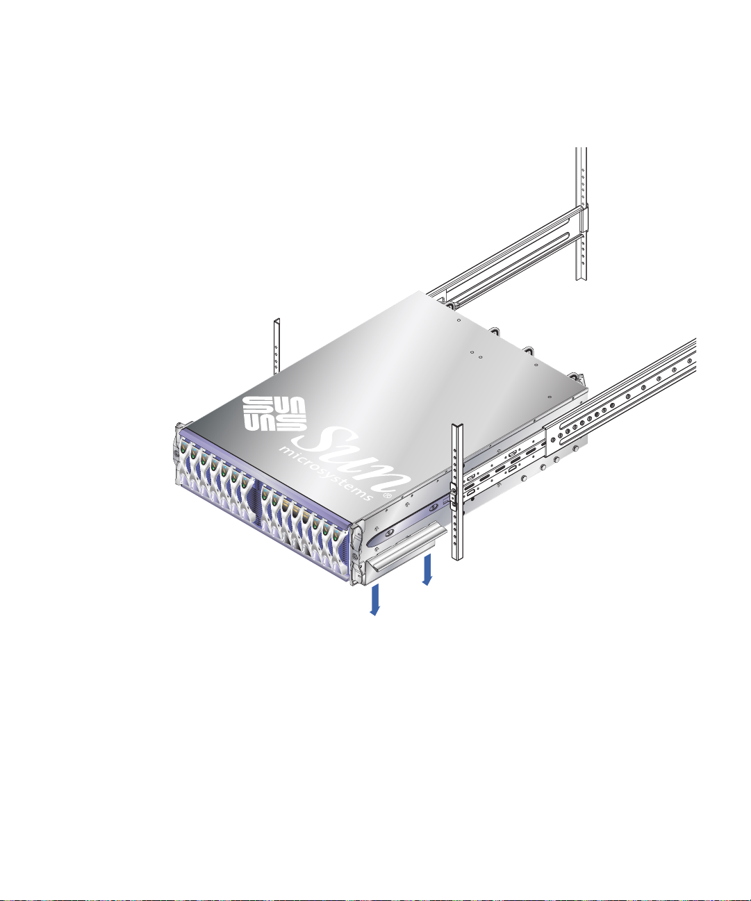
4. Hold the system chassis up to the rack and attach the front brackets (FIGURE 3-11).
Inner rack bracket
screw holes
FIGURE 3-11 Attaching the Front of the System Chassis to the Rack
(19-Inch, Two-Post Rack)
Caution – A fully populated system chassis weighs 99 lb (45 kg) approximately and
must be lifted by at least two people. A third person is required to attach the front
brackets to the rack.
Note – The two inner rack bracket screw holes are the rackmount holes identified
by the Rack Buddy. See Section 3.1.2, “Using the Rack Buddy” on page 3-2.
3-14 Sun Fire B1600 System Chassis Hardware Installation Guide • August 2003
Page 45

5. Attach the back brackets to the system chassis and to the two-post rack
(
FIGURE 3-12).
FIGURE 3-12 Attaching the Back Brackets (19-Inch, Two-Post Rack)
6. Go to Section 3.3, “What to Do Next” on page 3-16.
Chapter 3 Installing the System Chassis In a Rack or Cabinet 3-15
Page 46

3.3 What to Do Next
The Sun Fire B1600 blade system chassis can be installed as:
■ A fully populated system
■ A populated system chassis that requires the installation of blades
If you have installed a system chassis that requires blade installation, continue with
Chapter 4.
If you have installed a fully populated Sun Fire B1600 blade system chassis, continue
with Section 5.1, “Location of Ports and Power Inlets” on page 5-2.
3-16 Sun Fire B1600 System Chassis Hardware Installation Guide • August 2003
Page 47

CHAPTER
4
Removing and Installing Modules
This chapter provides instructions for installing Sun Fire B1600 server blades of filler
panels, Power Supply Units (PSUs) and Switch and System Controllers (SSC).
The Sun Fire B1600 blade system chassis can be ordered in two configuration
options:
■ A fully populated system chassis
A fully populated system chassis contains two Power Supply Units (PSUs),
two Switch and System Controllers (SSCs), and a combined total of up to 16
blades and filler panels.
■ A partially populated system chassis that requires the installation of blades
A partially populated system contains two Power Supply Units (PSUs), two
Switch and System Controllers (SSCs), and 16 filler panels.
This chapter provides the procedures for removing filler panels, if necessary, and
installing blades in the system chassis. It also provides instructions for removing and
inserting PSUs and SSCs while the system is powered down. It contains the
following sections:
■ Section 4.1, “Removing and Installing Blades or Filler Panels” on page 4-2
■ Section 4.2, “Removing and Installing a PSU” on page 4-9
■ Section 4.3, “Removing and Installing a Switch and System Controller (SSC)” on
page 4-15
■ Section 4.4, “What to Do Next” on page 4-22
Note – The procedures contained in this section assume that the system chassis is
unpowered. See the Sun Fire B1600 Blade System Chassis Administration Guide for
instructions on removing a module from a powered system chassis.
4-1
Page 48
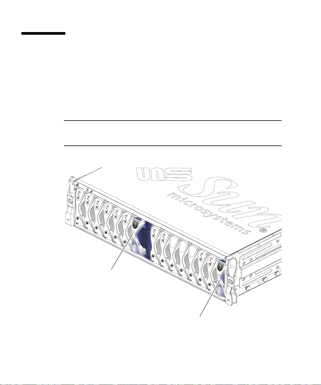
4.1 Removing and Installing Blades or Filler Panels
The system chassis contains 16 slots. It can hold a combination of single-width
blades, double-width blades and filler panels. Double-width blades occupy two
adjacent slots in the system chassis.
FIGURE 4-1 shows a system chassis containing single-width blades and a
double-width blade.
Note – Be aware that the system chassis contains three internal dividing walls.
Double-width blades must be installed in two available slots between these internal
dividing walls.
FILLER
PAN
EL
FILLER
PAN
EL
FILLER
PANEL
Double-Width Blade
Single-Width Blade
FIGURE 4-1 B1600 System Chassis with Single-width and Double-width Blades
4-2 Sun Fire B1600 System Chassis Hardware Installation Guide • August 2003
Page 49

4.1.1 Removing Blades or Filler Panels
The steps in this section refer to removal of a single-width blade. The same steps
apply when installing a double-width blade or filler panel.
1. Insert your finger in the pull recess located at the bottom front of the blade lever
and pull gently to disengage the locking mechanism (
FIGURE 4-2).
JBOS 3000
FIGURE 4-2 Disengaging the Blade Locking Mechanism
Chapter 4 Removing and Installing Modules 4-3
Page 50

2. Pull the lever in a forward and upward motion, causing the blade lever to unlatch
and eject the blade partially from the system chassis (
FIGURE 4-3).
JBOS 3000
FIGURE 4-3 Ejecting the Blade
4-4 Sun Fire B1600 System Chassis Hardware Installation Guide • August 2003
Page 51

3. Pull the lever to remove the blade from the system chassis (FIGURE 4-4).
Support the bottom of the blade with your free hand while lifting the blade clear of
the system chassis.
JBOS 3000
FIGURE 4-4 Removing the Blade
Chapter 4 Removing and Installing Modules 4-5
Page 52

4.1.2 Installing a Blade or Filler Panel
Note – Operating the system chassis with empty blade slots might disrupt airflow
through the system chassis and will compromise EMC compliance.
Note – Be aware that the system chassis contains three internal dividing walls.
Double-width blades must be installed in two available slots between these internal
dividing walls.
The steps below refer to installation of a single-width blade. The same steps apply
when installing a filler panel or double-width blade.
1. If required, open the blade lever by inserting a finger in the pull recess located in
lower portion of the blade lever and pull the lever in a forward and upward
motion, causing the lever to unlatch (
FIGURE 4-5).
Pull recess
FIGURE 4-5 Blade Locking Mechanism
4-6 Sun Fire B1600 System Chassis Hardware Installation Guide • August 2003
Page 53

2. Align the blade with the empty slot.
Ensure that the blade connector is facing towards the system chassis, with the hinge
point of the lever mechanism at the top. Support the bottom of the blade with your
free hand while lifting the blade up to the system chassis (
FIGURE 4-6).
JBOS 3000
FIGURE 4-6 Aligning and Inserting the Blade
3. Insert the blade into the empty slot.
Caution – Ensure that the blade engages with the system chassis guidance system.
Failure to align the blade correctly can result in damage to the chassis midplane or
the blade connection.
4. Gently push the blade into the slot until the blade latch ears, on top of the lever,
are positioned in the chassis.
Chapter 4 Removing and Installing Modules 4-7
Page 54

5. Close the blade lever fully by pushing it down until you feel the latch click in
place. This engages the blade into the chassis slot (
FIGURE 4-7).
JBOS 3000
FIGURE 4-7 Closing the Blade Lever Mechanism
4-8 Sun Fire B1600 System Chassis Hardware Installation Guide • August 2003
Page 55

4.2 Removing and Installing a PSU
Use the procedures in this section to remove and install a PSU. These are optional
procedures for you to familiarize yourself with the mechanism or to check the PSU
Serial Number.
Note – The procedures contained in this section assume that the system chassis is
unpowered. See the Sun Fire B1600 Blade System Chassis Administration Guide for
instructions on removing a PSU from a powered system chassis.
Caution – To ensure that it remains within an acceptable range of operating
temperatures the Sun Fire B1600 system chassis requires two PSUs.
Chapter 4 Removing and Installing Modules 4-9
Page 56

4.2.1 Removing a PSU
1. Squeeze the green PSU ejector lever to unlatch it and pull the lever towards you
to disconnect the PSU from the system chassis (
FIGURE 4-8).
FIGURE 4-8 PSU Ejector Lever
2. Check that the ejector lever is open fully and clear of the PSU module.
4-10 Sun Fire B1600 System Chassis Hardware Installation Guide • August 2003
Page 57

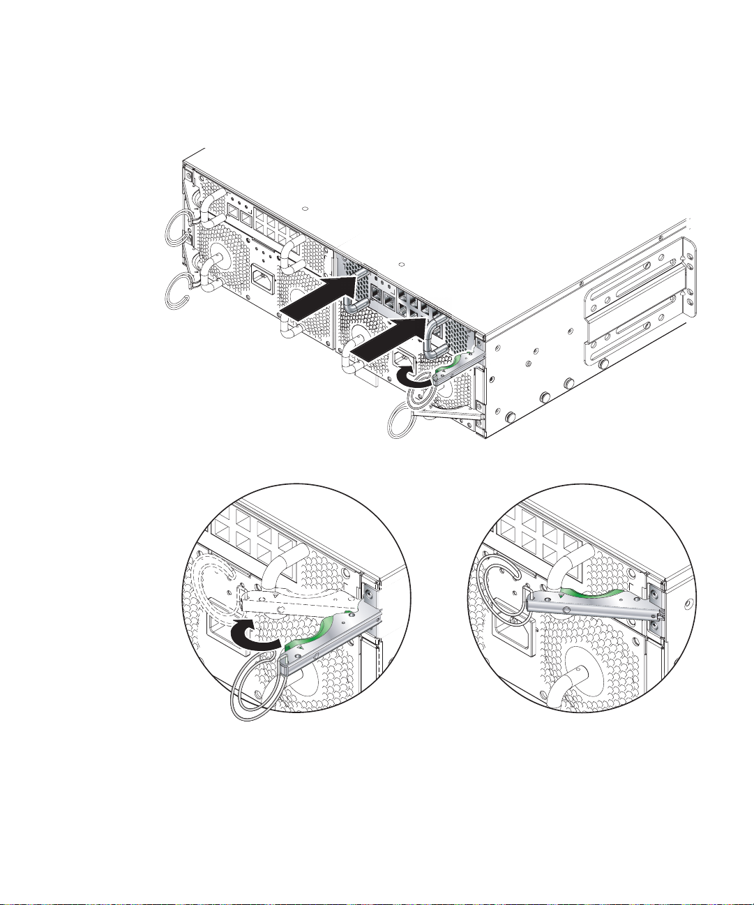
3. Remove the PSU from the system chassis by pulling on the vertical handles
attached to the rear of the PSU (
FIGURE 4-9).
Support the bottom of the PSU while removing the module from the system chassis.
Vertical Handles
FIGURE 4-9 Removing the PSU From the System Chassis
Chapter 4 Removing and Installing Modules 4-11
Page 58
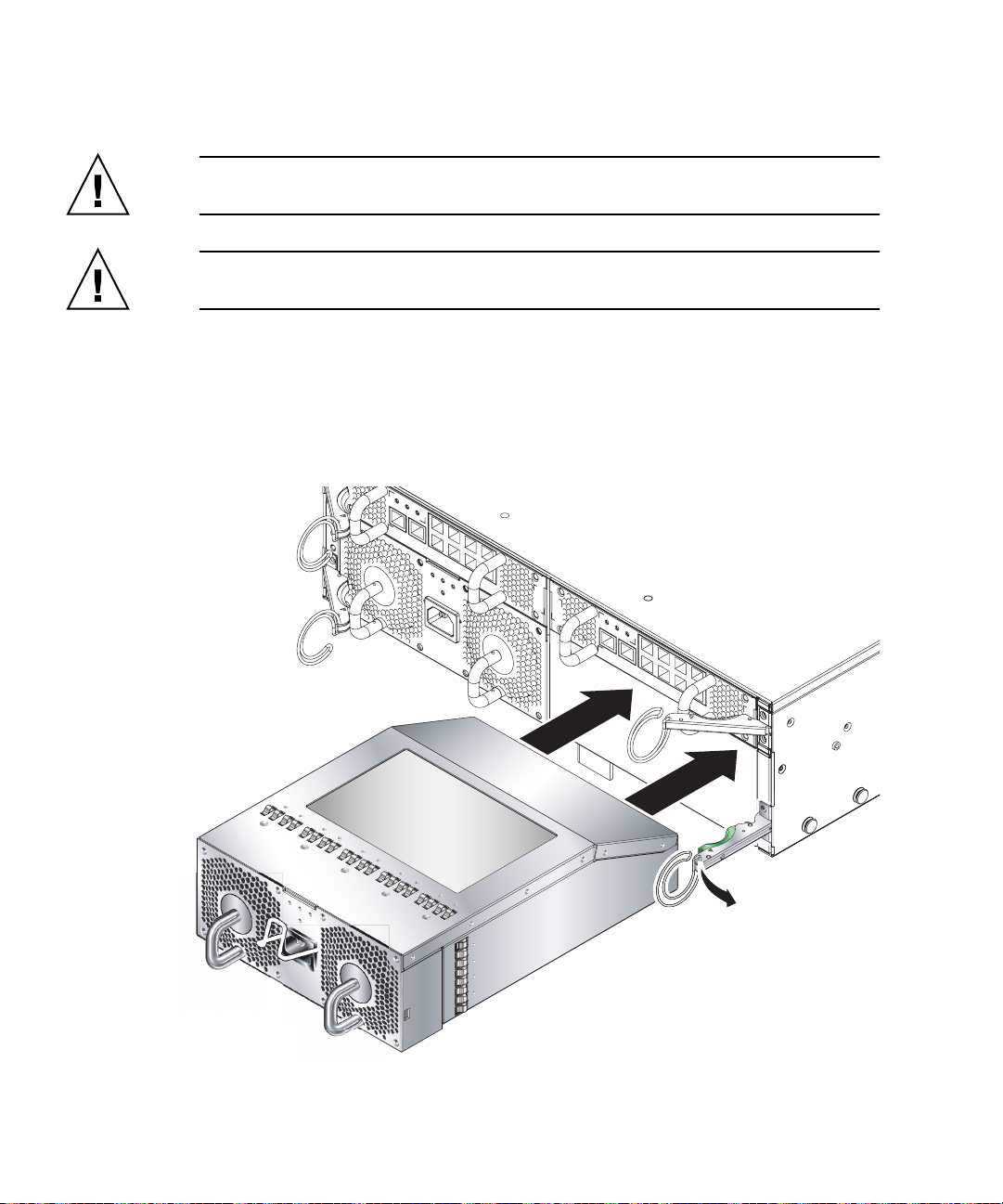
4.2.2 Inserting a PSU
Caution – To ensure that it remains within an acceptable range of operating
temperatures the Sun Fire B1600 system chassis requires two PSUs.
Caution – Do not install a PSU with the IEC power cord already attached. Only
connect the power cord when the PSU is installed.
1. Correctly align the PSU with the empty PSU slot in the system chassis.
PSU connectors must face towards the system chassis and be located on the lower
half of the PSU (
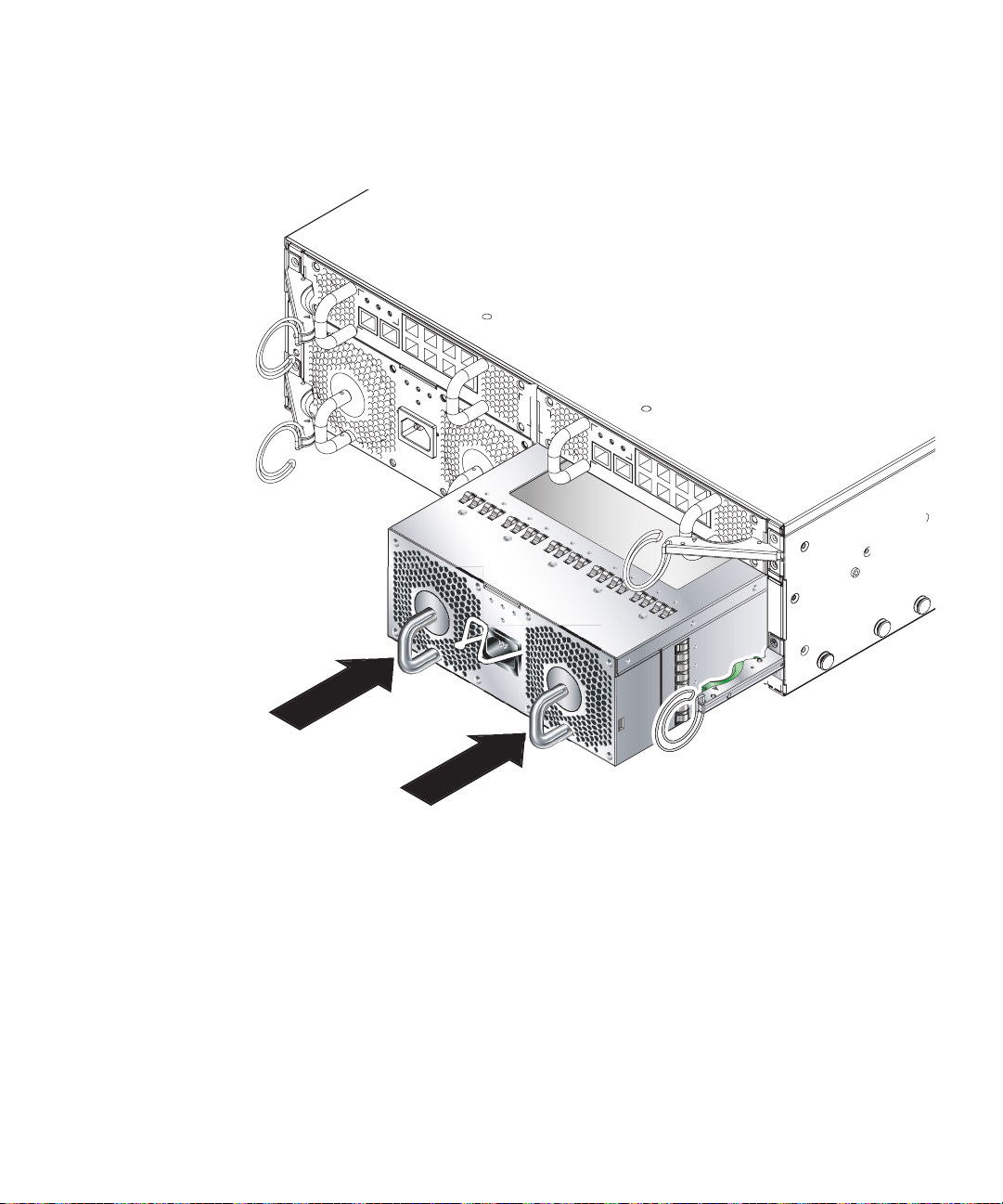
2. Check that the chassis ejector lever is opened fully and does not obstruct the
opening to the PSU slot (
FIGURE 4-10).
FIGURE 4-10).
FIGURE 4-10 Aligning the PSU
4-12 Sun Fire B1600 System Chassis Hardware Installation Guide • August 2003
Page 59
3. Slide the PSU into the empty PSU slot.
Push the PSU into the slot until the ejector lever engages (
FIGURE 4-11).
You must push the PSU firmly to raise the system flap within the system chassis.
FIGURE 4-11 Sliding the PSU in the System Chassis
Chapter 4 Removing and Installing Modules 4-13
Page 60

4. Complete the installation by closing the ejector lever fully.
Check that the ejector lever engages onto the PSU pull handle. This engages the PSU
into the system chassis (
FIGURE 4-12).
FIGURE 4-12 Closing the PSU Ejector Lever
4-14 Sun Fire B1600 System Chassis Hardware Installation Guide • August 2003
Page 61

4.3 Removing and Installing a Switch and System Controller (SSC)
Use the procedures in this section to remove and install an SSC. These are optional
procedures to enable you to familiarize yourself with the mechanism, or to check the
SSC Serial Number.
Note – The procedures contained in this section assume that the system chassis is
not connected to the network and is not powered up. See the Sun Fire B1600 Blade
System Chassis Administration Guide for instructions on removing an SSC from a
networked and powered system chassis.
4.3.1 Chassis Supplied With Only One SSC
If you have purchased a chassis containing only a single SSC, then the module in
slot SSC1 will be an SSC filler module (see
enclosure; it contains no functioning system hardware and you cannot connect a
serial cable or any network cables to it (it has no connectors).
Note – If you are removing a filler panel and replacing it with a new SSC, make sure
the currently installed SSC is using release 1.2 (or later) of the System Controller
firmware. (Also, if the module you are installing as a redundant SCC is not a new
one but is taken from another chassis and does not have release 1.2 firmware
installed on it, you need to upgrade it on the old chassis before installing it as a
redundant SSC.) Release 1.2 is the first firmware release to support failover (in other
words, to support the ability of two System Controllers to monitor each other’s
health, and of the standby System Controller to take over from the active one in the
event of a critical failure).
FIGURE 4-13). This is an empty metal
For full instructions about replacing an SSC filler module with a new SSC module,
and about upgrading the System Controller firmware on an SSC, refer to the Sun Fire
B1600 Blade System Chassis Administration Guide.
The mechanical procedures for removing and installing an SSC filler module are the
same as those for removing and installing an actual SSC module. They are described
in the remainder of this section.
Chapter 4 Removing and Installing Modules 4-15
Page 62
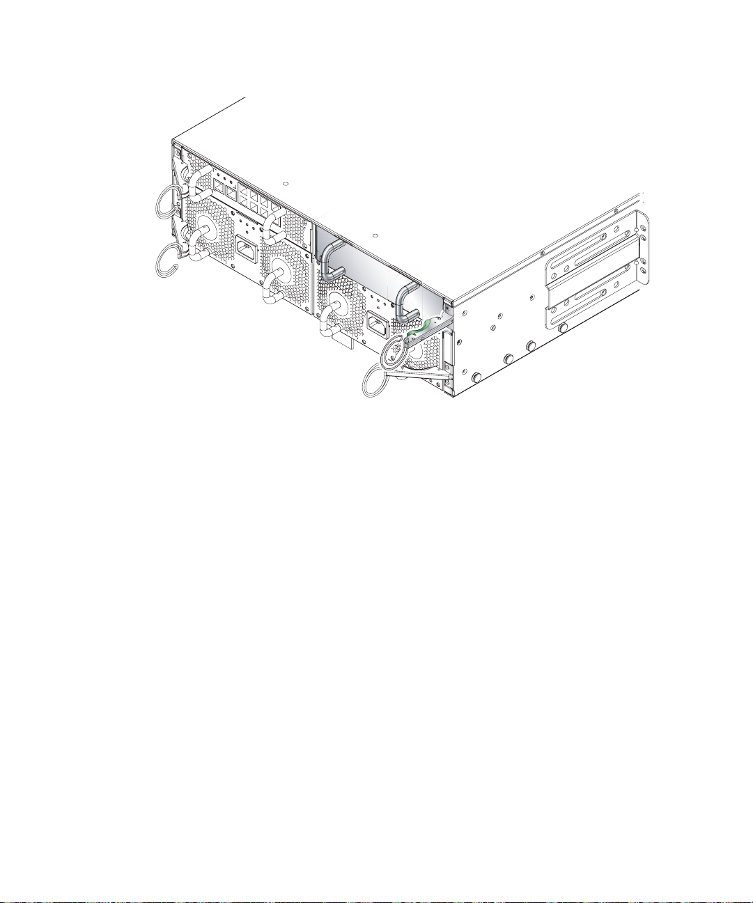
FIGURE 4-13 Rear View of the Chassis Showing a Filler Module in Slot SSC1
4-16 Sun Fire B1600 System Chassis Hardware Installation Guide • August 2003
Page 63

4.3.2 Removing the SSC
1. Squeeze the green SSC ejector lever to unlatch it, and then pull the lever towards
you to disconnect the SSC from the system chassis (
FIGURE 4-14).
FIGURE 4-14 SSC Ejector Lever
2. Check that the ejector lever is open fully and clear of the SSC module
(
FIGURE 4-14).
Chapter 4 Removing and Installing Modules 4-17
Page 64
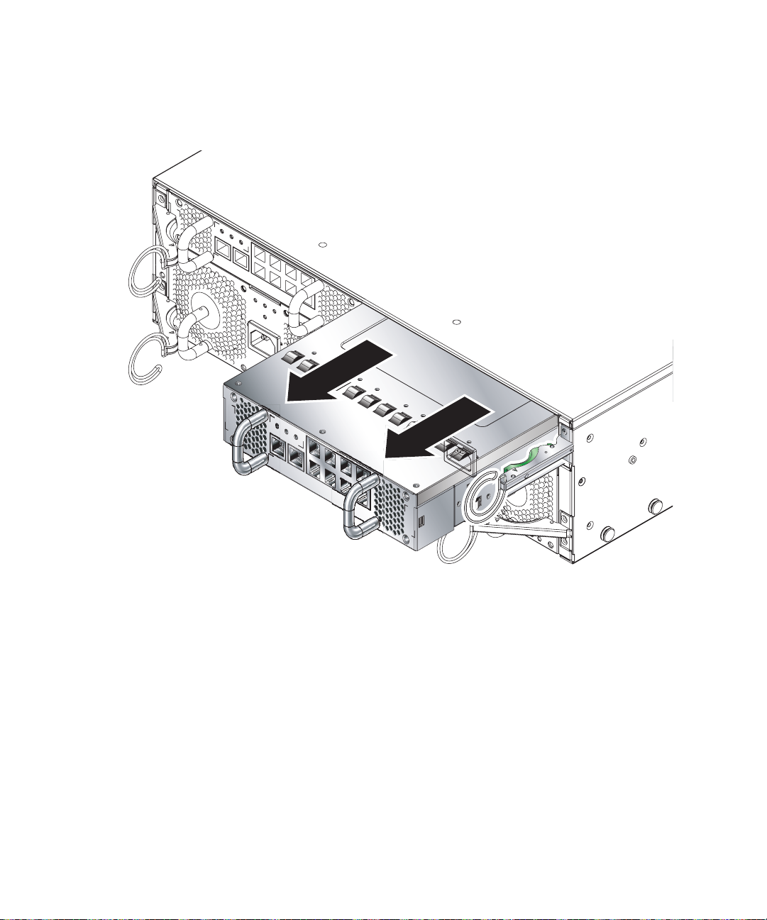
3. Remove the SSC from the system chassis by pulling on the vertical handles
attached to the back of the SSC (
FIGURE 4-15).
Support the bottom of the SSC while removing the module from the system chassis.
FIGURE 4-15 Removing the SSC From the System Chassis
4-18 Sun Fire B1600 System Chassis Hardware Installation Guide • August 2003
Page 65
4.3.3 Installing the SSC
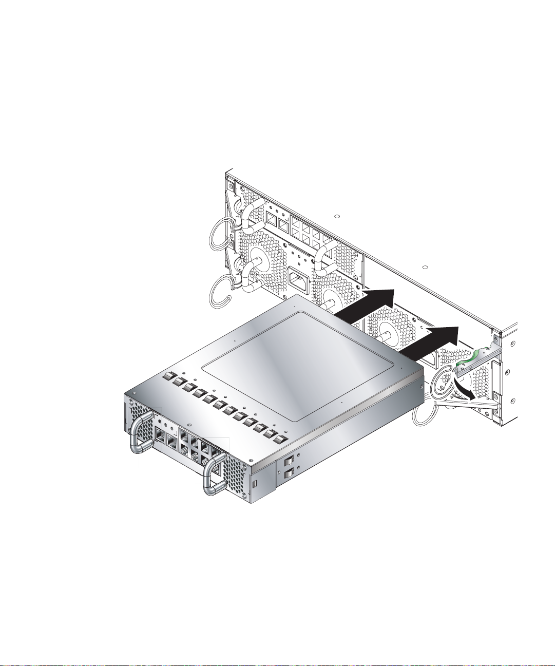
1. Align the SSC with the system chassis.
SSC connectors must face towards the system chassis and be located on the lower
half of the SSC.
2. Ensure that the chassis ejector lever is opened fully and does not obstruct the
chassis opening (
FIGURE 4-16).
FIGURE 4-16 Aligning the SSC Before Insertion
Chapter 4 Removing and Installing Modules 4-19
Page 66

3. Slide the SSC into the empty chassis slot.
Push the SSC into the slot until the ejector lever engages (
FIGURE 4-17).
FIGURE 4-17 Inserting the SSC
4-20 Sun Fire B1600 System Chassis Hardware Installation Guide • August 2003
Page 67
4. Complete insertion by closing the ejector lever.
Check that the latch engages onto the SSC pull handle. This engages the SSC into the
system chassis (
FIGURE 4-18).
FIGURE 4-18 Closing the SSC Ejector Lever
Chapter 4 Removing and Installing Modules 4-21
Page 68

4.4 What to Do Next
Now you have a fully populated Sun Fire B1600 blade system chassis, continue with
Section 5.1, “Location of Ports and Power Inlets” on page 5-2.
4-22 Sun Fire B1600 System Chassis Hardware Installation Guide • August 2003
Page 69

CHAPTER
5
Connecting and Managing Cables
This chapter contains the following sections:
■ Section 5.1, “Location of Ports and Power Inlets” on page 5-2
■ Section 5.2, “Connecting the IEC Power Cords” on page 5-3
■ Section 5.3, “Cable Requirements for 1000BASE-T and 10/100BASE-TX
Connections” on page 5-5
■ Section 5.4, “Attaching the Connector Cables” on page 5-6
■ Section 5.5, “Connecting to the 10/100/1000BASE-T Data Network Ports” on
page 5-7
■ Section 5.6, “Connecting to the 10/100BASE-T Network Management Ports” on
page 5-10
■ Section 5.7, “Managing Cables for Multiple System Chassis” on page 5-12
■ Section 5.8, “What to Do Next” on page 5-13
See Chapter 6 for details of Serial Port connections to other devices.
5-1
Page 70

5.1 Location of Ports and Power Inlets
FIGURE 5-1 shows the ports and power inlets at the back of the Sun Fire B1600 blade
system chassis.
10/100BASE-T network management port
RS232 serial console port
SSC 0
IEC power inlet
FIGURE 5-1 External Cable Ports (One SSC and PSU Shown)
10/100/1000BASE-T data
network ports
Caution – Do not connect a telephone jack connector to a RJ-45 port. This can
damage the switch. Instead, use only twisted-pair cables with RJ-45 connectors that
conform with FCC standards, and make sure you follow local national wiring or
electrical regulations.
5-2 Sun Fire B1600 System Chassis Hardware Installation Guide • August 2003
Page 71

5.2 Connecting the IEC Power Cords
You must connect an IEC power cord to each of the PSUs before you attach any
other cables. Connecting each power cord to a separate circuit breaker will ensure
that failure of one circuit does not compromise the system.
1. Connect the power cord to the IEC power inlet (
Note – The Sun B1600 blade system chassis powers on when the power cords are
connected. Connection of the power cord provides a reliable earth to ground.
FIGURE 5-2).
FIGURE 5-2 Inserting the IEC Power Cords
Chapter 5 Connecting and Managing Cables 5-3
Page 72

2. Confirm that the PSU LEDs are in the correct state.
If the PSU fans run at high speed and the blue and amber LEDs are lit on the PSU,
the unit might not be fully inserted into the system enclosure. See Section 4.3,
“Removing and Installing a PSU” on page 4-8 for details of how to install the PSU
correctly.
Caution – Do not attempt to install a PSU with the power cord attached.
3. Use the power cord retention clip to hold the power cord in position (
FIGURE 5-3).
FIGURE 5-3 Clipping on the Power Cord Retention Clip
4. Repeat Step 1 through to Step 3 for the other PSU.
5-4 Sun Fire B1600 System Chassis Hardware Installation Guide • August 2003
Page 73

5.3 Cable Requirements for 1000BASE-T and 10/100BASE-TX Connections
This section provides details of the 1000BASE-T and 10/100BASE-TX cable
requirements when connecting to a Sun Fire B1600 blade system chassis.
5.3.1 1000BASE-T Cable Requirements
All Category 5 UTP cables that are used for 100BASE-TX connections should also
work for 1000BASE-T connections, providing that all four wire pairs are connected.
However, for all critical connections or any new cable installations, use
Category 5E (enhanced Category 5) cable. The Category 5E specification includes
test parameters that are only recommendations for Category 5. Therefore, the first
step in preparing existing Category 5 UTP cable for running 1000BASE-T is a simple
test of the cable installation to confirm that it complies with the IEEE 802.3ab
standards.
5.3.1.1 Cable Testing for Existing Category 5 Cable
Installed Category 5 UTP cables must pass tests for Attenuation, Near-End Crosstalk
(NEXT), and Far-End Crosstalk (FEXT). This cable testing information is specified in
the ANSI/TIA/EIA-TSB-67 standard. Additionally, cables must also pass test
parameters for Return Loss, skew and Equal-Level Far-End Crosstalk (ELFEXT).
These tests are specified in the ANSI/TIA/EIA-TSB-95 Bulletin, “The Additional
Transmission Performance Guidelines for 100 Ohm 4-Pair Category 5 Cabling.”
Chapter 5 Connecting and Managing Cables 5-5
Page 74

5.3.2 Cable Requirements for 10/100BASE-TX Devices
The data ports on the SSC are designed to operate at an optimal speed of 1000 Mbps
but can be connected to 10 or 100 Mbytes/sec devices. The SSC also includes a
10/100BASE-TX management port. For 10/100BASE-TX connections, twisted-pair
cable can have two or four pairs of wires. Each wire pair is two different colors. For
example, one wire might be red, and the other red with white stripes. When
connecting the SSC to a device at 10 or 100 Mbytes/sec, use unshielded twisted-pair
(UTP) cable with RJ-45 connectors at both ends. For 100BASE-TX connections,
Category 5 cable is required. For 10BASE-T connections, Category 3, 4 or 5 cable can
be used.
Note – Twisted-pair cables must not exceed 100 meters (328 feet) in length.
Note – When connected to a shared collision domain (such as a hub with multiple
workstations), switch ports must be set to half-duplex mode and back pressure flow
control must be disabled to avoid propagating jamming packets throughout the
segment.
5.4 Attaching the Connector Cables
You must connect the power cords to the PSUs before you attach the remaining
cables:
■ RJ-45 10/100/1000BASE-T data network connectors
(see Section 5.5, “Connecting to the 10/100/1000BASE-T Data Network Ports” on
page 5-7 for further information)
■ RJ-45 10/100BASE-T network management connectors
(see Section 5.6, “Connecting to the 10/100BASE-T Network Management Ports”
on page 5-10 for further information)
■ RS232 serial connectors (see “Connecting the RS232 Serial Port to Different
Devices” on page 6-1 for further information)
Attach the RJ-45 connectors by inserting the connector into the relevant port until
the connector clicks in place.
5-6 Sun Fire B1600 System Chassis Hardware Installation Guide • August 2003
Page 75
The SSC is designed to connect to IEEE 802.3ab compliant devices. For most
applications, the external ports on the SSC will be connected to other switches in the
network backbone. It might also be connected directly to Gigabit Ethernet network
cards in PCs or servers.
Caution – Do not connect a telephone jack connector to any RJ-45 port. This can
damage the switch. Instead, use only twisted-pair cables with RJ-45 connectors that
conform with FCC standards, or local national wiring or electrical regulations.
5.5 Connecting to the 10/100/1000BASE-T Data Network Ports
4567
A B
81
81
BA
A B
81
81
BA
A B
81
81
BA
A B
81
81
BA
0123
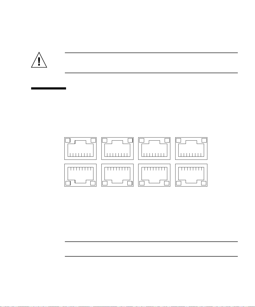
FIGURE 5-4 The 10/100/1000BASE-T Data Network Ports
The RJ-45 ports are arranged as a 4x2 array and provide the connection from the
Switch and System Controller (SSC) to the network.
Each port has integral green Link Present/Active and Link Speed LED indicators.
Note – The Link Present/Active indicator is always on the left, regardless of the
orientation of the RJ-45 port.
Chapter 5 Connecting and Managing Cables 5-7
Page 76

Note – The ce0 interface of each blade is connected to the switch in SSC0 and the
ce1 interface of each blade is connected to the switch in SSC1. Both switches run in
parallel, but separately.
TABLE 5-1 10/100/1000BASE-T Data Network Port Pinouts
Pin 1 TRD0+ Pin 2 TRD0-
Pin 3 TRD1+ Pin 4 TRD2+
Pin 5 TRD2- Pin 6 TRD1-
Pin 7 TRD3+ Pin 8 TRD3-
LED A Link
Present/
Active
LED B Link Speed:
On = 1000BASE-T
Off = 100BASE-T
When LED A is illuminated constantly it indicates that a link is established, but no
packets are being transferred. When LED A is flashing it indicates that a link is
established, and packets are being transferred.
FIGURE 5-5 shows how to connect the data network cables to the system chassis.
If you intend to configure your system chassis with redundant data connections, see
Chapter 3 of the Sun Fire B1600 Blade System Chassis Software Setup Guide for details
of how to duplicate connections from the SSC to your network.
5-8 Sun Fire B1600 System Chassis Hardware Installation Guide • August 2003
Page 77
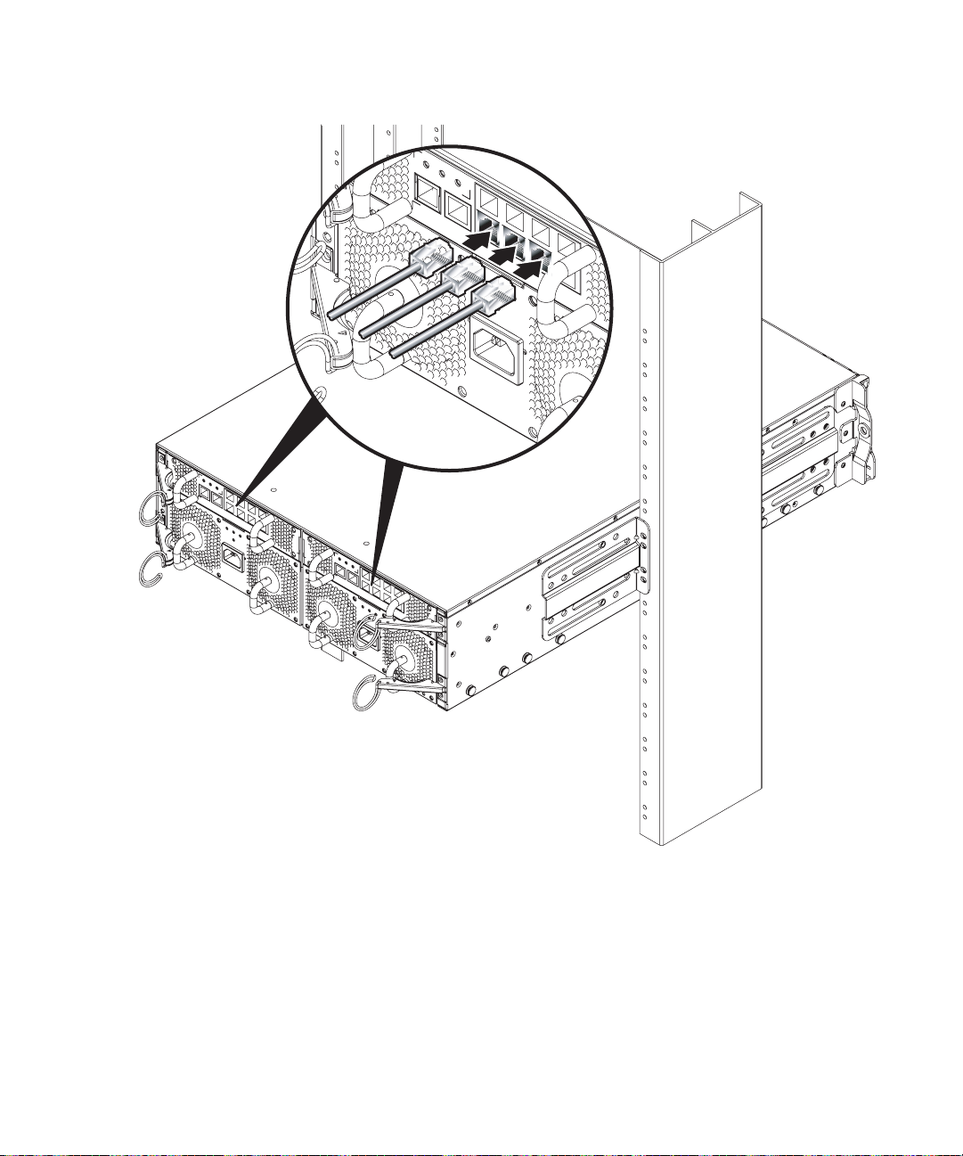
FIGURE 5-5 Attaching the Data Network Cables to the Network Ports
Chapter 5 Connecting and Managing Cables 5-9
Page 78
5.6 Connecting to the 10/100BASE-T Network Management Ports
These ports are labelled NET MGMT and are 10/100 Mbytes/sec Ethernet ports for
carrying network management traffic only. If you are concerned about the security of
your management network, we recommend strongly that you place the Network
Management port on a different subnet from the Data Network ports.
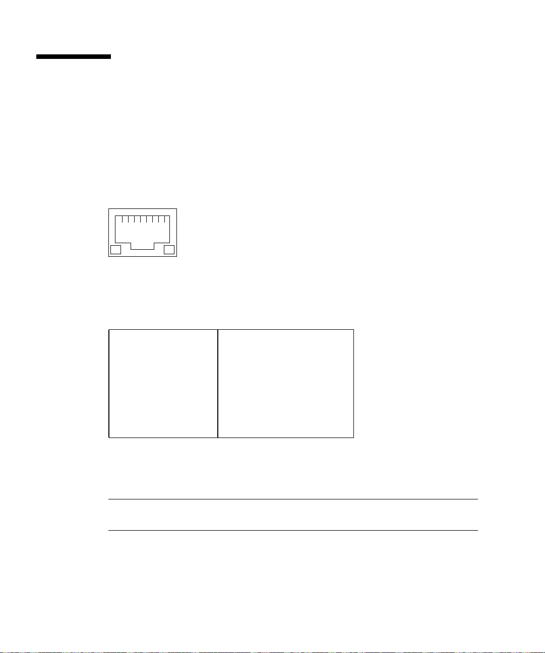
The port has integral green Link Present/Active and Link Speed indicators.
81
BA
FIGURE 5-6 10/100BASE-T Network Management Ports
TABLE 5-2 100BASE-T Network Management Port Pinouts
Pin 1 TXD+ Pin 2 TXD-
Pin 3 RXD+ Pin 4 4T_D3P
Pin 5 4T_D3P Pin 6 RXD-
Pin 7 4T_D4P Pin 8 4T_D4P
LED A Link
Present/
Active
LED B Link Speed:
On = 100BASE-T
Off = 10BASE-T
When LED A is illuminated constantly it indicates that a link is established, but no
packets are being transferred. When LED A is flashing it indicates that a link is
established and packets are being transferred.
Note – 4T_D3P and 4T_D4P pins provide a common-mode termination for unused
lines.
FIGURE 5-7 shows how to connect the network management cables to the system
chassis.
5-10 Sun Fire B1600 System Chassis Hardware Installation Guide • August 2003
Page 79

FIGURE 5-7 Attaching the Network Management Cables
Chapter 5 Connecting and Managing Cables 5-11
Page 80

5.7 Managing Cables for Multiple System Chassis
A Sun Fire B1600 blade system chassis that uses every available connection has
22 cables (including power cords) attached to the back of the system. When multiple
system chassis are installed within the same rack you must use effective cable
management to avoid blocking airflow through the system chassis.
Check that:
■ Cables are of an adequate length
■ There is adequate clearance at the back of the system chassis
■ The cabling from multiple system chassis does not block the back vents of any
system chassis that is installed beneath them
Cable management rings are attached to the module ejector handles on each PSU
and SSC. Use each ring to gather the cables from each module and to keep them
clear of the back system vents (
FIGURE 5-8).
SSC cable
management rings
PSU cable
management rings
FIGURE 5-8 Back Cable Management Rings
5-12 Sun Fire B1600 System Chassis Hardware Installation Guide • August 2003
Page 81

Caution – Failure to keep the vents at the back of the system chassis clear might
cause the system chassis to overheat and lead to system shutdown.
5.8 What to Do Next
See Chapter 6 for details of how to connect the Serial Port to different types of device
such as a:
■ Terminal server
■ VT100 terminal or Sun Workstation
■ Terminal that has a 9-pin adapter
■ Modem
Chapter 5 Connecting and Managing Cables 5-13
Page 82

5-14 Sun Fire B1600 System Chassis Hardware Installation Guide • August 2003
Page 83

CHAPTER
6
Connecting the RS232 Serial Port to Different Devices
To perform the initial configuration when you have installed and applied power to
the blade system chassis, you must either set up a serial connection to SSC0 or you
must set up a DHCP server to perform the IP configuration of the chassis’ active
System Controller automatically. If you set up a DHCP server to do this, you can
then telnet into the active System Controller to set up the chassis for the first time.
For information about configuring a DHCP server to enable you to connect to the
chassis’ active System Controller for the first time over a telnet instead of a serial
connection, see the Sun Fire B1600 Blade System Chassis Software Setup Guide.
Note – When both SSCs in the chassis are powered and working normally and
neither is damaged, by default SSC0 contains the active System Controller and SSC1
contains the standby System Controller. This means that, to set up the chassis for the
first time using a serial connection, you need a serial connection to at least SSC0.
However, for day-to-day operation of the blade system chassis, we recommend you
set up serial connections to both SSCs. This ensures that, if the active SSC fails for
any reason, you do not lose serial connectivity to the chassis.
This chapter contains the following sections:
■ Section 6.1, “Serial Port Pin Numbers” on page 6-2
■ Section 6.2, “Connecting to a Terminal Server” on page 6-3
■ Section 6.3, “Connecting to a VT100 Terminal or a Sun Workstation” on page 6-4
■ Section 6.4, “Connecting to a Terminal That Has a 9-pin Adapter” on page 6-5
■ Section 6.5, “Connecting to a Modem” on page 6-6
■ Section 6.6, “Connecting the Cable to the Serial Port” on page 6-7
■ Section 6.7, “Setting up a Serial Link to the System Controller Using a Laptop” on
page 6-8
6-1
Page 84

6.1 Serial Port Pin Numbers
When viewing the Sun Fire B1600 blade system chassis from the back, pin 1 of the
RJ-45 serial port is on the left, and pin 8 is on the right.
81
FIGURE 6-1 Serial Port Pin Numbers
TABLE 6-1 Serial Port Pinouts
Pin number on System
Chassis
Pin 1 RTS
Pin 2 DTR
Pin 3 TXD
Pin 4 Signal Ground
Pin 5 Signal Ground
Pin 6 RXD
Pin 7 DSR
Pin 8 CTS
Signal
6-2 Sun Fire B1600 System Chassis Hardware Installation Guide • August 2003
Page 85

6.2 Connecting to a Terminal Server
For this connection, you can use the standard RJ-45 patch cable and DB-25 adapter
supplied with the system chassis.
The serial port is a DTE port. You must be aware that if you are connecting a SSC’s
serial port to another DTE port - the pinouts for the serial ports on the SSCs
correspond with the pinouts for the RJ-45 ports on Cisco terminal servers. This
means that if you are using a Cisco AS2511-RJ terminal server you can:
■ Connect a rollover cable directly to the Sun Fire B1600 blade system chassis.
■ Connect a rollover cable to a patch panel and use a straight-through patch cable
to connect the patch panel to the Sun Fire B1600 blade system chassis (see
FIGURE 6-2).
Note – You do not have to use a Cisco terminal server. For other terminal servers,
see the manufacturer’s documentation to confirm whether the pinouts of the serial
ports on the terminal server match the pinouts of the Sun Fire B1600 system chassis.
If they do not, write down which pins on the terminal server’s serial ports carry the
signals listed in the right-hand column in
taking each of the pins on either SSC’s serial port to the correct pin on the terminal
server’s serial port.
TABLE 6-2. Then make a rollover cable
Terminal
server
Straight-through cable
Patch panel
Rollover cables
Sun Fire B1600
FIGURE 6-2 Patch Panel Connections to a Terminal Server
Chapter 6 Connecting the RS232 Serial Port to Different Devices 6-3
Page 86

TABLE 6-2 Serial Port Pinouts to a Terminal Server
Pin number on
System Chassis
Pin 1 RTS CTS
Pin 2 DTR DSR
Pin 3 TXD RXD
Pin 4 Signal Ground Signal Ground
Pin 5 Signal Ground Signal Ground
Pin 6 RXD TXD
Pin 7 DSR DTR
Pin 8 CTS RTS
Signal Terminal Server Signal
Connection
6.3 Connecting to a VT100 Terminal or a Sun Workstation
For this connection, you can use the standard RJ-45 patch cable supplied with the
chassis, but you must also use the DB-25 adapter that is supplied as well.
To configure the chassis directly from a VT100 terminal or a Sun workstation:
1. Connect one end of the serial cable to the serial port on the SSC.
2. Insert the other end of the serial cable into the DB-25 adapter
(part number 530-2889).
3. Plug the adapter into the DB-25 serial connector on the VT100 terminal or Sun
workstation you intend to use.
The DB-25 adapter supplied with your system chassis enables you to connect to any
Sun system. The pin interconnections are listed in
6-4 Sun Fire B1600 System Chassis Hardware Installation Guide • August 2003
TABLE 6-3.
Page 87

TABLE 6-3 Serial Port Pin Interconnections to a Sun DB-25 (25-pin) Adapter
Serial Port (RJ-45 Connector) Pin 25-pin Connector
Pin 1 (RTS) Pin 5 (CTS)
Pin 2 (DTR) Pin 6 (DSR)
Pin 3 (TXD) Pin 3 (RXD)
Pin 4 (Signal Ground) Pin 7 (Signal Ground)
Pin 5 (Signal Ground) Pin 7 (Signal Ground)
Pin 6 (RXD) Pin 2 (TXD)
Pin 7 (DSR) Pin 20 (DTR)
Pin 8 (CTS) Pin 4 (RTS)
6.4 Connecting to a Terminal That Has a 9-pin Adapter
The pinouts for the chassis serial ports correspond with the pinouts for the RJ-45
ports on the Cisco AS2511-RJ terminal server. For terminal servers from other
manufacturers, you might need to obtain a suitable rollover cable (see Section 6.2,
“Connecting to a Terminal Server” on page 6-3).
1. Connect one end of the serial cable to the serial port on the SSC.
2. Insert the other end of the serial cable into the DB-9 adapter.
Chapter 6 Connecting the RS232 Serial Port to Different Devices 6-5
Page 88

3. Plug the adapter into the DB-9 serial connector on the terminal you intend to use.
The DB-9 (9-pin) adapter must perform the pin interconnections listed in
TABLE 6-4 Serial Port Pin Interconnections to a DB-9 (9-pin) Adapter
Serial Port (RJ-45 Connector) Pin 9-pin Connector
Pin 1 (RTS) Pin 8 (CTS)
Pin 2 (DTR) Pin 6 (DSR)
Pin 3 (TXD) Pin 2 (RXD)
Pin 4 (Signal Ground) Pin 5 (Signal Ground)
Pin 5 (Signal Ground) Pin 5 (Signal Ground)
Pin 6 (RXD) Pin 3 (TXD)
Pin 7 (DSR) Pin 4 (DTR)
Pin 8 (CTS) Pin 7 (RTS)
6.5 Connecting to a Modem
For this connection, you can use the standard RJ-45 patch cable and the DB-25
adapter supplied with the server.
TABLE 6-4.
1. Connect one end of the serial cable to the serial port on the SSC.
2. Insert the other end of the serial cable into the DB-25 adapter that was supplied
with the system chassis (part number 530-2889).
3. Plug the adapter into the DB-25 serial connector on the modem.
The settings you need to use for a modem connection are listed in
TABLE 6-5 Default Settings for Connecting a Modem to the Serial Port
Parameter Setting
Rate 9600 baud
Parity No
Stop bits 1
Data bits 8
6-6 Sun Fire B1600 System Chassis Hardware Installation Guide • August 2003
TABLE 6-5.
Page 89

6.6 Connecting the Cable to the Serial Port
FIGURE 6-3 Attaching the Serial Cables
Chapter 6 Connecting the RS232 Serial Port to Different Devices 6-7
Page 90

6.7 Setting up a Serial Link to the System Controller Using a Laptop
This section describes how to connect from a laptop computer to one of the Sun Fire
B1600 blade system chassis’s two Switch and System Controller (SSC) modules to
access the chassis’s command-line management interface.
Note – Make sure you have installed the blade system chassis into a rack or cabinet
(refer to Chapter 3) before following the instructions in this chapter.
6.7.1 Connecting to a Laptop
Note – Do not attempt to use the laptop’s (25-pin) parallel port instead of its serial
port. The serial port is a male 9-pin D-type connector.
1. Connect the RJ-45 to RJ-45 patch cable (supplied with the chassis) to the
SSC’s serial port.
2. Connect the other end of the patch cable to the RJ-45 connector on the silvercolored DB25 (25-way DSUB male-to-female 8 POS RJ-45) adapter (part number
530-2889-0x) supplied with the Sun Fire B1600.
6-8 Sun Fire B1600 System Chassis Hardware Installation Guide • August 2003
Page 91
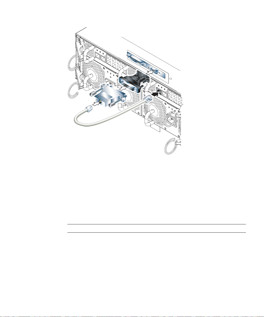
Laptop
Sun Fire B1600 Blade System Chassis
FIGURE 6-4 Connecting the SSC to the Serial Port on a Laptop
3. Connect the 25-way D-type male connector to an adapter that has one 25-way
female connector and one 9-way D-type female connector.
Sun does not supply a 25x9-way D-type female-to-female adapter. However,
adapters like this are available from home computer suppliers and electronics stores.
The pin inter-connections that the adapter must perform are listed in
TABLE 6-6.
TABLE 6-6 Pin Inter-connections Required to be Performed by the 25x9-way D-type
Female-to-Female Adapter
9-way Female Connector 25-way Female Connector
Pin 1 Pin 8
Pin 2 Pin 3
Pin 3 Pin 2
Pin 4 Pin 20
Pin 5 Pin 7
Pin 6 Pin 6
Chapter 6 Connecting the RS232 Serial Port to Different Devices 6-9
Page 92

TABLE 6-6 Pin Inter-connections Required to be Performed by the 25x9-way D-type
Female-to-Female Adapter
9-way Female Connector 25-way Female Connector
Pin 7 Pin 4
Pin 8 Pin 5
Pin 9 Pin 22
4. Finally, connect the 9-way female connector to the serial port on the laptop.
6.7.1.1 Using Microsoft Windows HyperTerminal
Note – If you normally connect the serial port on your laptop to a handheld device,
you must close the Hot Sync Manager before following the instructions in this
section. Otherwise you will not be able to use the serial port to communicate with
the Sun Fire B1600 Blade System Chassis.
The instructions in this section were verified on a laptop PC running Microsoft
Windows 98 and with HyperTerminal Applet version 3.0.
1. Run the Windows HyperTerminal utility.
2. In the HyperTerminal window, double-click the Hypertrm.exe icon.
3. In the Connection Description window, specify a name for the HyperTerminal
connection you are creating on the laptop.
Then select an icon for it and click OK.
4. In the Connect to... window, click the arrow for the “Connect using” option and
select the port you are using for your connection to the server.
Unless you have a particular reason for using a different port, select DIRECT TO
COM1. Click OK.
5. In the COM1 Properties Port Settings window, set the parameters as follows:
Bits per second: 9600
Data bits: 8
Parity: None
Stop bits: 1
Flow control: specify either “Xon/Xoff” or “None”.
Note – Do not select “Hardware” for the Flow control option.
6-10 Sun Fire B1600 System Chassis Hardware Installation Guide • August 2003
Page 93

Click OK.
6. Your HyperTerminal session is now active. From the File menu, select Properties.
7. In the Properties window, click the Settings tab.
On the Settings tab, click the arrow for the “Emulation” option and select VT100. For
the “Telnet terminal” option, specify VT100. Click OK.
6.8 What to Do Next
For information on how to configure the system controllers, Switches and blades
within the system chassis, see the Sun Fire B1600 Blade System Chassis Software Setup
Guide.
Chapter 6 Connecting the RS232 Serial Port to Different Devices 6-11
Page 94

6-12 Sun Fire B1600 System Chassis Hardware Installation Guide • August 2003
Page 95

Index
A
airflow
direction of, 1-11
protruding units or cables, 2-2
requirements, 1-11
B
blade
alignment with the system chassis, 4-7
ejecting the blade, 4-4
installing a blade, 4-6
pull recess, 4-3
removal, 4-2, 4-3
C
cabinet door access requirements, 2-2
cabinets
see rack
cables
1000BASE-T cable requirements, 5-5
cable requirements for 10/100BASE-TX
devices, 5-6
cable testing for existing category 5 cable, 5-5
category 5 UTP cables, 5-5
category 5E (enhanced category 5) cable, 5-5
external cable ports, 5-2
maximum length of twisted-pair cables, 5-6
captive retaining screws, tightening, 3-10
Cisco AS2511-RJ terminal server, 6-6
connecting the cables
connecting to the serial port, 6-8
to a modem, 6-7
to a Sun workstation, 6-5
to a terminal server, 6-4
to a terminal that has a 9-pin adapter, 6-6
to a VT100 terminal or Sun workstation, 6-5
cooling requirements, 1-8
crossover cable, 6-5, 6-7
D
DB-25 adapter, 6-5, 6-7
DB-25 serial connector, 6-5
DB-9 adapter, 6-6
dimension constraints, 1-6
dimensions, 1-4
door panel preferences, 1-11
E
EIA/RETMA mounting hole pattern
dimensions, 2-2
environmental parameters, 1-8
environmental specifications, 1-8
F
filler panel
Index-1
Page 96

alignment with the system chassis, 4-7
ejecting the filler panel, 4-4
installing a filler panel, 4-6
pull recess, 4-3
removal, 4-2, 4-3
floor loading, 2-3
formula for heat dissipation, 1-11
free-standing racks, 2-3
H
heat dissipation, 1-11
I
inlet and exhaust ventilation, 1-11
L
laptop
connecting to chassis from, 6-9
lifting requirements, 1-3
M
manuals, 1-3
mechanical loading hazard, 2-3
Microsoft Windows
using Windows Hyperterminal, 6-11
modem
connecting to the serial port, 6-7
default settings, 6-7
module retaining pins, removing, 3-7, 3-12
mounting requirements, 2-1
N
null modem cable, 6-5, 6-7
P
packaging, 1-3
patch cable
connecting to a terminal server, 6-4
pin interconnections
to a DB-9 adapter, 6-7
to a Sun DB-25 adapter, 6-6
pinouts
to a terminal server, 6-5
power
estimating power consumption, 1-12
power consumption of individual
components, 1-12
power limits and ranges, 1-12
Power Supply Unit
see PSU
PSU
closing the ejector lever, 4-12
ejector lever, 4-10
inserting, 4-12
number of PSUs required, 4-9
removing, 4-10
R
rack
contents of the four-post rakmount kit, 3-2
rack options, 2-1
vertical mounting hole pattern, 2-2
rack and cabinet safety, 2-3
Rack Buddy, 3-2
rack installation
attaching the four-post rack brackets, 3-3
contents of the two-post rackmount kit, 3-11
four-post rack bracket spacer, 3-5
identification of two-post rackmount holes, 3-14
removing the back sacrificial lifting handle (four-
post installation), 3-7
removing the front sacrificial lifting handle (four-
post installation), 3-9
tightening the captive retaining screws (four-
post), 3-10
two-post rack installation, 3-11
using rack stability features, 3-6
retaining pins, removing, 3-7, 3-12
retaining screws, tightening, 3-10
rollover cable, 6-6
Index-2 Sun Fire B1600 System Chassis Hardware Installation Guide • August 2003
Page 97

S
serial port
pin numbers, 6-3
service access, 2-2
shared collision domain, connecting to, 5-6
shipkit contents, 1-3
space required, 1-4
SSC
closing the SSC ejector lever, 4-21
installing the SSC, 4-19
removing the SSC, 4-17
Sun Fire B1600 blade system chassis
estimating heat dissipation, 1-11
Sun workstation, connecting to the serial port, 6-5
Switch and System Controller
see SSC
T
temperature
operating ambient temperature, 2-3
terminal server, 6-4
twisted-pair cables, maximum length, 5-6
V
VT100 terminal, connecting to the serial port, 6-5
W
weight considerations, 2-3
weight distribution hazard, 2-3
Index-3
Page 98

Index-4 Sun Fire B1600 System Chassis Hardware Installation Guide • August 2003
 Loading...