

Page 1

Sun Fire
Systems Service Manual
™
6800/4810/4800/3800
Sun Microsystems, Inc.
www.sun.com
Part No. 805-7363-15 v2
May 2008, Revision A
Submit comments about this document at: http://www.sun.com/hwdocs/feedback
Page 2

Copyright 2008Sun Microsystems, Inc., 4150 Network Circle, SantaClara, CA 95054 USA. All rights reserved.
This product ordocument is protected by copyright and distributed under licenses restricting its use, copying, distribution, and decompilation.
No partof this product or document may be reproduced inany form by any meanswithout prior written authorization of Sun and its licensors,
if any. Third-party software, includingfont technology, is copyrighted and licensedfrom Sun suppliers.
Parts ofthe product may be derived from BerkeleyBSD systems, licensed from the University ofCalifornia. UNIX is a registered trademark in
the U.S.and other countries, exclusively licensedthrough X/Open Company, Ltd.
Sun, SunMicrosystems, the Sun logo, AnswerBook2, docs.sun.com, Sun Fire, and Solaris are trademarks, registered trademarks, or service
marks ofSun Microsystems, Inc. in the U.S. and other countries. All SPARC trademarksare usedunder license and are trademarks or registered
trademarks ofSPARCInternational, Inc. in the U.S.and other countries.Products bearing SPARC trademarks are based upon an architecture
developed bySun Microsystems, Inc .
The OPENLOOK and Sun™ Graphical UserInterface was developedby Sun Microsystems, Inc. for its users and licensees. Sun acknowledges
the pioneeringefforts of Xerox in researching and developing the concept of visual or graphical user interfaces forthe computer industry. Sun
holds anon-exclusive license from Xerox to the Xerox Graphical User Interface, which license also covers Sun’s licensees who implement OPEN
LOOK GUIsand otherwise comply with Sun’swritten license agreements.
U.S. GovernmentRights-Commercial use. Government users are subject tothe Sun Microsystems, Inc. standard license agreement and
applicable provisions ofthe FAR and its supplements.
DOCUMENTATION IS PROVIDED “AS IS” AND ALL EXPRESS OR IMPLIED CONDITIONS, REPRESENTATIONS AND WARRANTIES,
INCLUDING ANY IMPLIED WARRANTY OF MERCHANTABILITY, FITNESS FOR A PARTICULAR PURPOSE OR NONINFRINGEMENT, ARE DISCLAIMED, EXCEPT TO THE EXTENT THAT SUCH DISCLAIMERS ARE HELD TO BE LEGALLY INVALID.
Copyright 2008Sun Microsystems, Inc., 4150 Network Circle, SantaClara, CA 95054 Etats-Unis. Tous droits réservés.
Ce produit oudocument est protégé par un copyright etdistribué avec des licences qui en restreignent l’utilisation, la copie,la distribution, et la
décompilation. Aucunepartie de ce produit ou document ne peut être reproduite sous aucune forme, par quelque moyenque ce soit, sans
l’autorisation préalableet écrite de Sun etde ses bailleurs de licence,s’il y en a. Le logiciel détenu par des tiers, et qui comprend la technologie
relative aux polices de caractères, est protégé par un copyright etlicencié par des fournisseurs deSun.
Des partiesde ce produit pourront être dérivées des systèmes Berkeley BSD licenciés par l’Université de Californie. UNIX estune marque
déposée aux Etats-Unis et dans d’autres pays et licenciée exclusivement par X/Open Company, Ltd.
Sun, SunMicrosystems, le logo Sun, AnswerBook2, docs.sun.com, Sun Fire, et Solaris sont des marques defabrique ou des marques déposées,
ou marques deservice, de Sun Microsystems, Inc. aux Etats-Unis et dans d’autres pays. Toutes les marques SPARC sont utilisées sous licence et
sont desmarques defabrique oudes marques déposées de SPARC International, Inc. aux Etats-Unis et dans d’autres pays. Les produits portant
les marques SPARC sont basés sur unearchitecture développée par Sun Microsystems, Inc.
L’interfaced’utilisation graphique OPEN LOOK et Sun™ a été développée par Sun Microsystems,Inc. pour ses utilisateurs et licenciés. Sun
reconnaît les efforts depionniers de Xerox pour la recherche et le développementdu concept des interfaces d’utilisation visuelle ou graphique
pour l’industriede l’informatique. Sun détient unelicence non exclusive de Xerox surl’interface d’utilisation graphique Xerox, cette licence
couvrant également les licenciés deSun qui mettent en placel’interface d’utilisation graphique OPEN LOOKet qui en outre se conforment aux
licences écritesde Sun.
CETTE PUBLICATION EST FOURNIE "EN L’ETAT" ET AUCUNE GARANTIE, EXPRESSE OU IMPLICITE, N’EST ACCORDEE, Y
COMPRIS DES GARANTIES CONCERNANT LA VALEUR MARCHANDE, L’APTITUDE DE LA PUBLICATION A REPONDRE A UNE
UTILISATION PARTICULIERE, OU LE FAIT QU’ELLE NE SOIT PAS CONTREFAISANTE DE PRODUIT DE TIERS. CE DENI DE
GARANTIE NE S’APPLIQUERAIT PAS, DANS LA MESURE OU IL SERAIT TENU JURIDIQUEMENT NUL ET NON AVENU.
Please
Recycle
Page 3

Contents
Preface xxi
1. Safety and Tools Requirements 1–1
1.1 Safety Precautions 1–1
1.2 Symbols 1–2
1.3 System Precautions 1–3
1.3.1 Captive Screws 1–3
1.3.2 Fan Speed Message 1–3
1.3.3 Sun Fire Cabinet Fan Tray Power Switches 1–4
1.3.4 Firmware On Replacement Boards and Assemblies 1–4
1.3.5 Switzerland Caution 1–4
1.4 Filler Boards and Filler Panels 1–5
1.5 Periodic Maintenance 1–5
1.6 Tools Required 1–6
2. Powering Off and On 2–1
2.1 Powering Off the System 2–1
2.2 Powering On the System 2–6
3. FrameManager 3–1
3.1 FrameManager Description 3–1
iii
Page 4

3.2 FrameManager LEDs 3–2
3.3 Replacing the FrameManager 3–2
4. Power 4–1
4.1 Power Supplies 4–1
4.1.1 Power Supply Slot Locations 4–2
4.1.2 Power Supply LEDs 4–7
4.1.3 Replacing a Sun Fire 6800/4810 System Power Supply 4–7
4.1.4 Replacing a Sun Fire 4800 System Power Supply 4–9
4.1.5 Replacing a Sun Fire 3800 System Power Supply 4–11
4.2 AC Input Box 4–13
4.2.1 Replacing the AC Input Box 4–16
4.3 Redundant Transfer Unit (RTU) and Redundant Transfer Switch (RTS) 4–
17
4.3.1 Replacing the RTS Modules 4–20
4.3.2 Replacing the RTU Assembly 4–21
5. Patch Panel 5–1
5.1 Patch Panel 5–1
5.2 Replacing the Patch Panel 5–2
6. Fan Trays 6–1
6.1 Fan Tray Slot Numbering 6–2
6.2 Fan Tray LEDs 6–5
6.3 Replacing Fan Trays in Sun Fire 6800/4810/4800 Systems 6–5
6.3.1 Removing a Fan Tray 6–5
6.3.2 Installing a Fan Tray 6–6
6.4 Replacing Fan Trays in a Sun Fire 3800 System 6–7
6.4.1 Removing a Fan Tray 6–7
6.4.2 Installing a Fan Tray 6–8
iv Sun Fire 6800/4810/4800/3800 Systems Service Manual • May 2008
Page 5

6.5 Cabinet Fan Trays 6–9
6.5.1 Replacing the Cabinet Fan Trays 6–10
7. System Controller Board 7–1
7.1 Handling Boards and Assemblies 7–1
7.2 System Controller Board 7–2
7.2.1 System Controller Board Slot Locations 7–4
7.2.2 System Controller Board LEDs 7–8
7.2.3 Resetting the System Controller Board 7–9
7.2.4 Replacing a System Controller Board 7–10
8. CPU/Memory Boards and Components 8–1
8.1 Handling Boards and Assemblies 8–1
8.2 Filler Panels and Filler Boards 8–3
8.3 CPU/Memory Boards 8–3
8.3.1 Replacing CPU/Memory Boards 8–7
8.3.2 Replacing DIMMs 8–13
8.4 CPU/Memory Board EMI Springfingers Clip 8–18
8.4.1 Replacing the EMI Springfingers Clip for Sun Fire 6800/4810/4800
Systems 8–18
9. PCI I/O Assemblies and Components 9–1
9.1 Handling Boards and Assemblies 9–1
9.2 Filler Boards and Filler Panels 9–3
9.3 PCI I/O Assemblies 9–4
9.3.1 PCI I/O Assembly Location Requirements 9–4
9.3.2 I/O Assembly LEDs 9–8
9.3.3 Replacing PCI I/O Assemblies 9–8
9.3.4 Replacing PCI Cards 9–11
10. CompactPCI I/O Assemblies and Components 10–1
Contents v
Page 6

10.1 Handling Boards and Assemblies 10–1
10.2 Filler Panels and CompactPCI Filler Cards 10–3
10.3 CompactPCI I/O Assembly 10–3
10.3.1 CompactPCI I/O Assembly Location Requirements 10–4
10.3.2 I/O Assembly Status LEDs 10–8
10.3.3 Replacing CompactPCI I/O Assemblies 10–9
10.3.4 Replacing CompactPCI Cards 10–11
11. Repeater Board 11–1
11.1 Handling Boards and Assemblies 11–1
11.2 Filler Boards 11–2
11.3 Repeater Board 11–2
11.3.1 Replacing Repeater Boards 11–7
12. Centerplane and ID Boards 12–1
12.1 Replacing the Centerplanes in a Sun Fire 6800 System 12–1
12.1.1 Removing the System Centerplane 12–2
12.1.2 Removing the Fan Centerplane 12–8
12.1.3 Removing the Power Centerplane 12–9
12.1.4 Installing the System Centerplane 12–12
12.1.5 Installing the Fan Centerplane 12–12
12.1.6 Replacing the Power Centerplane 12–13
12.2 Replacing the Centerplanes in a Sun Fire 4810 System 12–14
12.2.1 Removing the System Centerplane or the Power Centerplane 12–
14
12.2.2 Installing the System Centerplane or the Power Centerplane 12–
18
12.3 Replacing the Centerplane in a Sun Fire 4800 System 12–20
12.3.1 Removing the Centerplane 12–20
12.3.2 Installing the Centerplane 12–29
vi Sun Fire 6800/4810/4800/3800 Systems Service Manual • May 2008
Page 7

12.4 Replacing the Centerplane in a Sun Fire 3800 System 12–30
12.4.1 Removing the Centerplane 12–30
12.4.2 Installing the Centerplane 12–38
12.5 Replacing the Sun Fire 3800 System LED Board 12–41
12.5.1 Removing the LED Board 12–41
12.5.2 Installing the LED Board 12–43
12.6 Replacing the ID Boards 12–44
12.6.1 Removing the ID Board From the Sun Fire 6800 System 12–44
12.6.2 Installing the ID Board in the Sun Fire 6800 System 12–46
12.6.3 Removing the ID Board From the Sun Fire 4810 System 12–47
12.6.4 Installing the ID board in the Sun Fire 4810 System 12–49
12.6.5 Removing the ID board From the Sun Fire 4800 System 12–49
12.6.6 Installing the ID board in the Sun Fire 4800 System 12–50
13. Periodic Maintenance 13–1
13.1 Cleaning the Air Intake Screen 13–2
13.2 Air Intake Screen for the Sun Fire 6800 System 13–2
13.2.1 Replacing the Sun Fire 6800 Air Intake Screen 13–3
13.3 Air Intake Screen for the Sun Fire 4810 System 13–4
13.3.1 Replacing the Sun Fire 4810 Air Intake Screen 13–5
13.4 Air Intake Screen for the Sun Fire 4800 System 13–6
13.4.1 Replacing the Sun Fire 4800 Air Intake Screen 13–7
A. Functional Description A–1
A.1 System Overview A–1
A.2 System Packaging A–2
A.2.1 Sun Fire 6800 System A–2
A.2.2 Sun Fire 4810 System A–4
A.2.3 Sun Fire 4800 System A–5
Contents vii
Page 8

A.2.4 Sun Fire 3800 System A–6
A.3 Software A–8
A.3.1 System Controller Software A–8
A.3.2 FrameManager Software A–8
A.4 Device Hot-Plug Procedures A–9
A.5 CPU/Memory Board A–10
A.5.1 CPU Processors A–12
A.5.2 Ecache Modules A–12
A.5.3 DIMMs A–12
A.6 I/O Assemblies A–12
A.6.1 PCI I/O Assembly A–13
A.6.2 Compact PCI I/O Assembly A–14
A.7 Power Supplies A–16
A.8 Fan Trays A–18
A.9 System Controller Board A–19
B. System Serial Number Locations and Rules for System Configuration B–1
B.1 System Serial Number Locations B–1
B.1.1 Location for the Sun Fire 6800 System B–1
B.1.2 Location for the Sun Fire 4810 System B–3
B.1.3 Location for the Sun Fire 4800 System B–4
B.1.4 Location for the Sun Fire 3800 System B–4
B.2 Boards and Assemblies B–7
B.2.1 CPU/Memory and CPU/Memory+ Boards B–7
B.2.2 I/O Assemblies B–8
B.2.3 Repeater Boards B–9
B.2.4 System Controller Board B–9
B.3 Filler Boards and Filler Panels B–10
B.4 Fan Trays B–11
viii Sun Fire 6800/4810/4800/3800 Systems Service Manual • May 2008
Page 9

B.5 Power Supplies B–11
B.6 Connecting Cables B–12
B.6.1 Ethernet B–12
B.6.2 Serial Port B–12
C. Illustrated Parts Breakdown C–1
C.1 List of Replacement Parts C–1
C.1.1 Sun Fire 6800 System Replacement Parts C–2
C.1.2 Sun Fire 4810 System Replacement Parts C–5
C.1.3 Sun Fire 4800 System Replacement Parts C–7
C.1.4 Sun Fire 3800 System Replacement Parts C–10
C.1.5 CPU/Memory Board Replacement Parts C–12
C.1.6 I/O Assembly Replacement Parts C–13
C.1.7 Repeater Board Replacement Part C–15
C.1.8 System Controller Board C–16
C.1.9 Power Supply Replacement Parts C–17
C.1.10 Filler Boards and Filler Panels Replacement Parts C–19
C.1.11 Cables Replacement Parts C–20
Glossary Glossary–1
Index Index–1
Contents ix
Page 10

x Sun Fire 6800/4810/4800/3800 Systems Service Manual • May 2008
Page 11

Figures
FIGURE 2-1 Sun Fire System Cabinet Showing FrameManager—Top View 2-1
FIGURE 2-2 AC Input Boxes—Sun Fire 6800 System—Rear View 2-2
FIGURE 2-3 AC Input Box—Sun Fire 4810 System—Front View 2-2
FIGURE 2-4 AC Input Box—Sun Fire 4800 System—Rear View 2-3
FIGURE 2-5 Sun Fire 3800 System Power Supplies—Rear View 2-4
FIGURE 2-6 Redundant Transfer Switches (RTS)—Sun Fire 6800 System 2-5
FIGURE 2-7 Redundant Transfer Switches (RTS)—Sun Fire 4810 System 2-5
FIGURE 2-8 Sun Fire Cabinet RTU Circuit Breakers and RTS Power Switch 2-6
FIGURE 2-9 Cabinet Fan Tray Power Switch—Sun Fire 6800 System Rear View 2-7
FIGURE 3-1 FrameManager 3-1
FIGURE 3-2 FrameManager Removal—Step 1 3-3
FIGURE 3-3 FrameManager Removal—Step 2 3-3
FIGURE 3-4 FrameManager Cable Location 3-4
FIGURE 4-1 Power Supply Locations—Sun Fire 6800 System—Front View 4-3
FIGURE 4-2 Power Supplies in Power Grid 0 and Power Grid 1—Sun Fire 6800 System 4-4
FIGURE 4-3 Power Supply Locations—Sun Fire 4800 System—Front View 4-5
FIGURE 4-4 Power Supply Locations—Sun Fire 4810 System—Front View 4-5
FIGURE 4-5 Power Supply Locations—Sun Fire 3800 System—Front View 4-6
FIGURE 4-6 Removing or Replacing a Power Supply—Sun Fire 6800 System 4-8
FIGURE 4-7 Removing or Replacing a Power Supply—Sun Fire 4800 System 4-10
xi
Page 12

FIGURE 4-8 Removing or Replacing a Power Supply—Sun Fire 3800 System 4-12
FIGURE 4-9 AC Input Box—Sun Fire 6800 System 4-14
FIGURE 4-10 AC Input Box—Sun Fire 4800 System 4-14
FIGURE 4-11 AC Input Box—Sun Fire 4810 System 4-15
FIGURE 4-12 AC Input Boxes—Sun Fire 6800 System—Rear View 4-15
FIGURE 4-13 Two Captive Screws on the AC Input Box—Sun Fire 6800 System 4-16
FIGURE 4-14 Removing the AC Input Box—Sun Fire 6800 System 4-17
FIGURE 4-15 RTU and RTS Modules 4-18
FIGURE 4-16 RTS Modules—Sun Fire 4810 System—Rear View 4-20
FIGURE 4-17 RTS Modules—Sun Fire 6800 System 4-20
FIGURE 4-18 RTU Assembly 4-21
FIGURE 5-1 Patch Panel Location—Rear View 5-1
FIGURE 6-1 Front and Rear Fan Trays—Sun Fire 6800 System 6-3
FIGURE 6-2 Fan Trays—Sun Fire 4810 System 6-3
FIGURE 6-3 Fan Trays—Sun Fire 4800 System 6-4
FIGURE 6-4 Fan Trays—Sun Fire 3800 System 6-4
FIGURE 6-5 Removing or Replacing a Front Fan Tray—Sun Fire 6800 System 6-6
FIGURE 6-6 Removing or Replacing a Fan Tray—Sun Fire 3800 System 6-8
FIGURE 6-7 Cabinet Fan Trays 6-9
FIGURE 6-8 Cabinet Fan Tray Power Switch and Connectors 6-10
FIGURE 6-9 Cabinet Fan Tray Top Plate 6-11
FIGURE 7-1 System Controller Board for Sun Fire 6800/4810/4800 Systems 7-3
FIGURE 7-2 System Controller Board for the Sun Fire 3800 System 7-3
FIGURE 7-3 System Controller Board Slot Assignments for the Sun Fire 6800 System—Front View 7-5
FIGURE 7-4 System Controller Board Slot Assignments for the Sun Fire 4810 System—Front View 7-6
FIGURE 7-5 System Controller Board Slot Assignments for the Sun Fire 4800 System—Rear View 7-7
FIGURE 7-6 System Controller Board Slot Assignments for the Sun Fire 3800 System—Front View 7-8
FIGURE 7-7 Reset Switch on a System Controller Board 7-10
xii Sun Fire 6800/4810/4800/3800 Systems Service Manual • May 2008
Page 13

FIGURE 7-8 Loosening the Captive Screws and Ejector Levers 7-12
FIGURE 7-9 Removing and Replacing a System Controller Board—Sun Fire 6800 System 7-13
FIGURE 7-10 Removing and Replacing a System Controller Board—Sun Fire 3800 System 7-14
FIGURE 7-11 Tightening the Captive Screws and Locking the Ejector Levers 7-15
FIGURE 8-1 CPU/Memory Board With the Cover Installed 8-4
FIGURE 8-2 CPU/Memory Board Slot Assignments—Sun Fire 6800 System—Front View 8-5
FIGURE 8-3 CPU/Memory Board Slot Assignments—Sun Fire 4810 System—Front View 8-6
FIGURE 8-4 CPU/Memory Board Slot Assignments—Sun Fire 4800 System—Rear View 8-6
FIGURE 8-5 CPU/Memory Board Slot Assignments—Sun Fire 3800 System—Front View 8-7
FIGURE 8-6 Unlocking the Ejector Levers 8-9
FIGURE 8-7 Removing or Replacing a CPU/Memory Board—Sun Fire 6800 System 8-10
FIGURE 8-8 Removing and Replacing a CPU/Memory Board—Sun Fire 3800 System 8-11
FIGURE 8-9 DIMM Slot Numbers 8-14
FIGURE 8-10 Removing a DIMM 8-16
FIGURE 8-11 Installing a DIMM 8-17
FIGURE 8-12 Removing a CPU/Memory Board EMI Springfingers Clip 8-19
FIGURE 8-13 Installing a CPU/Memory Board EMI Springfingers Clip 8-21
FIGURE 9-1 I/O Assemblies for the Sun Fire 6800 System—Rear View 9-5
FIGURE 9-2 I/O Assemblies for the Sun Fire 4810 System—Front View 9-6
FIGURE 9-3 I/O Assemblies for the Sun Fire 4800 System—Rear View 9-7
FIGURE 9-4 PCI I/O Assembly 9-9
FIGURE 9-5 Removing or Inserting an I/O Assembly—Sun Fire 4810 System 9-10
FIGURE 9-6 Removing a PCI Card From the I/O Assembly 9-12
FIGURE 10-1 I/O Assemblies for the Sun Fire 6800 System—Rear View 10-5
FIGURE 10-2 I/O Assemblies for the Sun Fire 4810 System—Front View 10-6
FIGURE 10-3 I/O Assemblies for the Sun Fire 4800 System—Rear View 10-7
FIGURE 10-4 I/O Assemblies for the Sun Fire 3800 System—Front View 10-8
FIGURE 10-5 Removing or Inserting a CompactPCI I/O Assembly—Sun Fire 3800 System 10-10
Figures xiii
Page 14

FIGURE 10-6 Removing a CompactPCI Card 10-13
FIGURE 10-7 Replacing a CompactPCI Card 10-15
FIGURE 11-1 Repeater Board Slot Assignments for the Sun Fire 6800 System—Rear View 11-3
FIGURE 11-2 Repeater Board Slot Assignments for the Sun Fire 4810 System—Front View 11-4
FIGURE 11-3 Repeater Board Slot Assignments for the Sun Fire 4800 System—Rear View 11-4
FIGURE 11-4 Repeater Board LEDs 11-6
FIGURE 11-5 Unlocking the Ejector Levers 11-8
FIGURE 11-6 Removing and Replacing a Repeater Board—Sun Fire 6800 System 11-9
FIGURE 12-1 Removing the Door—Sun Fire 6800 System 12-2
FIGURE 12-2 Removing All Components From the Front of the Sun Fire 6800 System 12-3
FIGURE 12-3 Removing the Bus Bar Access Panels 12-4
FIGURE 12-4 Loosening the Bus Bar Captive Screws—Sun Fire 6800 System 12-5
FIGURE 12-5 Disconnecting the Two Cables From the System Centerplane—Sun Fire 6800 System 12-6
FIGURE 12-6 Removing the Screws Securing the System Centerplane—Sun Fire 6800 System 12-6
FIGURE 12-7 Moving the System Centerplane Forward Off the Guide Pins—Sun Fire 6800 System 12-7
FIGURE 12-8 Removing the System Centerplane—Sun Fire 6800 System 12-7
FIGURE 12-9 Disconnecting the Fan Tray Centerplane Cables 12-8
FIGURE 12-10 Removing the Screws Securing the Fan Centerplane 12-9
FIGURE 12-11 Centerplane Cables—Sun Fire 6800 System 12-10
FIGURE 12-12 Disconnecting the Screws Securing the Power Centerplane Bus Bars 12-11
FIGURE 12-13 Removing All Boards, Fan Trays, AC Input Box, and Power Supplies From the Front of the
Sun Fire 4810 System 12-15
FIGURE 12-14 Rear Screen Panel—Sun Fire 4810 System 12-16
FIGURE 12-15 Disconnecting the Signal Cable—Sun Fire 4810 System 12-16
FIGURE 12-16 Removing the Screws Securing the Cover to the Bus Bar and Removing the Bus Bar
Insulator—Sun Fire 4810 System 12-17
FIGURE 12-17 Removing the Bus Bar—Sun Fire 4810 System 12-17
FIGURE 12-18 Removing the System Centerplane— Sun Fire 4810 System 12-18
FIGURE 12-19 Removing the Bottom Fan Tray, CPU/Memory Boards, and I/O
Assemblies—Sun Fire 4800 System 12-21
xiv Sun Fire 6800/4810/4800/3800 Systems Service Manual • May 2008
Page 15

FIGURE 12-20 Removing the Front Door—Sun Fire 4800 System 12-22
FIGURE 12-21 Removing a Power Supply at the Front of the Sun Fire 4800 System 12-23
FIGURE 12-22 Disconnecting Cables From the Connectors on the Centerplane—Sun Fire 4800
System 12-24
FIGURE 12-23 Removing the Top and Bottom Power Supply Supports—Sun Fire 4800 System 12-25
FIGURE 12-24 Removing the Cable Guide—Sun Fire 4800 System 12-26
FIGURE 12-25 Removing the Screws Securing the Centerplane to the System—Sun Fire 4800 System 12-
27
FIGURE 12-26 Removing the Centerplane and Insulator—Sun Fire 4800 System 12-28
FIGURE 12-27 Removing the Boards—Sun Fire 3800 System 12-31
FIGURE 12-28 Disconnecting the LED Cable—Sun Fire 3800 System 12-32
FIGURE 12-29 Removing a Fan Tray—Sun Fire 3800 System 12-33
FIGURE 12-30 Removing a Power Supply—Sun Fire 3800 System 12-34
FIGURE 12-31 Removing the Clamp—Sun Fire 3800 System 12-35
FIGURE 12-32 Removing the Subchassis 12-36
FIGURE 12-33 Removing the Lower Bulkhead 12-36
FIGURE 12-34 Removing the Centerplane—Sun Fire 3800 System 12-37
FIGURE 12-35 Removing the I/O Assembly—Sun Fire 3800 System 12-42
FIGURE 12-36 Disconnecting the LED Cable From the Centerplane—Sun Fire 3800 System 12-42
FIGURE 12-37 Removing IB9 I/O Assembly—Sun Fire 6800 System 12-45
FIGURE 12-38 Removing the ID Board From the Centerplane—Sun Fire 6800 System 12-46
FIGURE 12-39 Removing IB8 I/O Assembly—Sun Fire 4810 System 12-47
FIGURE 12-40 Removing the ID board From the Centerplane—Sun Fire 4810 System 12-48
FIGURE 13-1 Air Intake Screen Location for the Sun Fire 6800—Front View 13-2
FIGURE 13-2 Air Intake Screen Location for the Sun Fire 4810—Front View 13-4
FIGURE 13-3 Air Intake Screen Location for the Sun Fire 4800—Front View 13-6
FIGURE A-1 Sun Fire 6800 System—Front and Rear Views A-3
FIGURE A-2 Sun Fire 4810 System Mounted in Sun Fire Cabinet—Front and Rear Views A-4
FIGURE A-3 Sun Fire 4800 System—Front and Rear Views A-5
Figures xv
Page 16

FIGURE A-4 Sun Fire 3800 System—Front View A-6
FIGURE A-5 Sun Fire 3800 System—Rear View A-7
FIGURE A-6 FrameManager Software Release 1.2 LCD Display A-9
FIGURE A-7 CPU/Memory Board With the Cover Removed A-11
FIGURE A-8 PCI I/O Assembly A-13
FIGURE A-9 PCI Card A-14
FIGURE A-10 CompactPCI I/O Assembly—Sun Fire 3800 System A-14
FIGURE A-11 CompactPCI I/O Assembly—Sun Fire 6800/4810/4800 Systems A-16
FIGURE A-12 Power Supply for the Sun Fire 6800 and Sun Fire 4810 Systems A-17
FIGURE A-13 Power Supply for the Sun Fire 3800 System A-17
FIGURE A-14 Power Supply for the Sun Fire 4800 System A-18
FIGURE A-15 System Controller Board—Sun Fire 6800/4810/4800 Systems A-20
FIGURE A-16 System Controller Board—Sun Fire 3800 System A-20
FIGURE B-1 Serial Number Location for the Sun Fire 6800 System—Rear B-2
FIGURE B-2 Serial Number Location for the Sun Fire 4810 System—Front B-3
FIGURE B-3 Serial Number Location for the Sun Fire 4800 System—Rear B-4
FIGURE B-4 Serial Number Location for the Sun Fire 3800 System—Rear B-5
FIGURE B-5 Sun Fire Cabinet System Serial Number Location—Rear B-6
FIGURE C-1 Sun Fire 6800 System—Front and Rear Views C-2
FIGURE C-2 Sun Fire 6800 System Cabinet C-4
FIGURE C-3 Sun Fire 4810 System Mounted in Optional Sun Fire Cabinet—Front View C-5
FIGURE C-4 Sun Fire 4800 System—Rear View C-7
FIGURE C-5 Sun Fire 4800 System—Front View C-8
FIGURE C-6 Sun Fire 3800 System—Front View C-10
FIGURE C-7 Sun Fire 3800 System—Rear View C-11
FIGURE C-8 CPU/Memory Board C-12
FIGURE C-9 PCI I/O Assembly C-13
FIGURE C-10 CompactPCI I/O Assembly for the Sun Fire 3800 System C-13
xvi Sun Fire 6800/4810/4800/3800 Systems Service Manual • May 2008
Page 17

FIGURE C-11 CompactPCI I/O Assembly for the Sun Fire 6800/4810/4800 Systems C-14
FIGURE C-12 Repeater Board C-15
FIGURE C-13 System Controller Board—Sun Fire 6800/4810/4800 Systems C-16
FIGURE C-14 System Controller Board—Sun Fire 3800 System C-16
FIGURE C-15 Power Supply for the Sun Fire 6800/4810 Systems C-17
FIGURE C-16 Power Supply for the Sun Fire 3800 System C-18
FIGURE C-17 Power Supply for the Sun Fire 4800 System C-18
Figures xvii
Page 18

xviii Sun Fire 6800/4810/4800/3800 Systems Service Manual • May 2008
Page 19

Tables
TABLE P-1 Typographic Conventions xxiii
TABLE 1-1 Safety Precautions 1–1
TABLE 1-2 Symbols 1–2
TABLE 1-3 Overheating Precautions Using Filler Boards 1–5
TABLE 3-1 FrameManager LED Major Functions 3–2
TABLE 4-1 Specifications for the Power Supplies 4–2
TABLE 4-2 Power Supply Slot Locations 4–2
TABLE 4-3 Power Supply LED Functions 4–7
TABLE 4-4 RTS LED Functions 4–19
TABLE 4-5 Self-Test LED Functions 4–19
TABLE 6-1 Fan Trays and Their Slot Numbers 6–2
TABLE 6-2 Fan Tray LED Functions 6–5
TABLE 6-3 Default Fan Tray Configuration 6–9
TABLE 7-1 System Controller Board Slot Locations for All Systems 7–4
TABLE 7-2 System Controller Board LED Functions 7–8
TABLE 8-1 CPU/Memory Board LED Functions 8–3
TABLE 8-2 CPU/Memory Board Slot Locations 8–5
TABLE 9-1 Description of the PCI I/O Assembly 9–4
TABLE 9-2 Location of the I/O Assemblies 9–4
TABLE 9-3 I/O Assembly Status LED Functions 9–8
xix
Page 20

TABLE 10-1 Description of the CompactPCI I/O Assembly 10–3
TABLE 10-2 Location of the I/O Assemblies 10–4
TABLE 10-3 I/O Assembly Status LED Functions 10–8
TABLE 10-4 I/O Card Status LED Functions 10–12
TABLE 11-1 Repeater Board Slot Locations 11–3
TABLE 11-2 Repeater Board LED Functions 11–5
TABLE 12-1 Default Fan Tray Configuration 12–40
TABLE A-1 Sun Fire 6800 System Components A–2
TABLE A-2 FrameManager LCD Displays A–8
TABLE A-3 FrameManager LED Functions A–9
TABLE A-4 CPU/Memory Board Slot Locations A–11
TABLE A-5 I/O Assembly Slot Locations A–12
TABLE A-6 I/O Assemblies A–15
TABLE A-7 Number of Fan Trays, CPU Fan Trays, and Blower Assemblies A–18
TABLE B-1 Overheating Precautions Using Filler Panels and Filler Boards B–10
xx Sun Fire 6800/4810/4800/3800 Systems Service Manual • May 2008
Page 21

Preface
This document describes how to remove and install field-replaceable units (FRUs).
This document also presents a functional description of the systems, configuration
rules, and illustrated parts breakdowns for each system.
Who Should Use This Document
Caution – This document is written for qualified service-trained maintenance
providers. If you are not a qualified service-trained maintenance provider and you
service the system, your warranty on the system will be void.
xxi
Page 22

How This Document Is Organized
This document contains the following chapters and appendixes:
Chapter 1 describes the safety precautions and tools you will need.
Chapter 2 describes how to power on and power off the system.
Chapter 3 describes how to install and remove the FrameManager.
Chapter 4 describes how to install and remove the power supplies, the AC input
box, the redundant transfer unit (RTU), and the redundant transfer switches (RTS).
Chapter 5 describes how to install and remove the patch panel.
Chapter 6 describes how to install and remove the fan trays.
Chapter 7 describes how to install and remove the System Controller board.
Chapter 8 describes how to install and remove the CPU/Memory board, DIMMs
(Dual Inline Memory Modules), and EMI springfingers clip.
Chapter 9 describes how to install and remove the PCI I/O assembly and how to
install and remove the cards in the I/O assembly.
Chapter 10 describes how to install and remove the CompactPCI I/O assembly and
how to install and remove the CompactPCI cards in the I/O assembly.
Chapter 11 describes how to install and remove the Repeater board.
Chapter 12 describes how to install and remove the centerplane.
Chapter 13 describes how to perform the periodic maintenance tasks for Sun Fire
systems.
Appendix A presents a functional description of the systems; the card cage layout
and the layout of various boards, such as the CPU/Memory board and the I/O
assembly.
Appendix B describes system serial number locations and rules for system
configuration.
Appendix C provides illustrations of the field-replaceable units.
xxii Sun Fire 6800/4810/4800/3800 Systems Service Manual • May 2008
Page 23

Typographic Conventions
TABLE P-1 Typographic Conventions
Typeface Meaning Examples
AaBbCc123 The names of commands, files,
and directories; on-screen
computer output
AaBbCc123 Document titles, new words or
terms, words to be emphasized
Edit your .login file.
Use ls -a to list all files.
Read Chapter 6 in the User’s Guide.
These are called class options.
You must be superuser to do this.
Related Documentation
Application Title
Installation Sun Fire 6800 System Getting Started
Sun Fire 4810/4800/3800 Systems Getting Started
Sun Fire 6800 System Installation Guide
Sun Fire 4810/4800/3800 Systems Installation Guide
Sun Fire 4810/4800/3800 Systems Cabinet Mounting Guide
Operation Sun Fire Cabinet Installation and Reference Guide
Software Sun Fire Midrange Systems Platform Administration Manual
Sun Fire 6800/4810/4800/3800 Systems Overview Manual
Sun Fire Midrange Systems Controller Command Reference Manual
Sun Fire Midrange Systems Dynamic Reconfiguration User Guide
Preface xxiii
Page 24

Accessing Sun Documentation
You can view, print, or purchase a broad selection of Sun documentation, including
localized versions, at:
http://www.sun.com/documentation
Sun Welcomes Your Comments
Sun is interested in improving its documentation and welcomes your comments and
suggestions. You can email your comments to Sun at:
http://www.sun.com/hwdocs/feedback
Please include the part number (805-7363-15) of your document in the subject line of
your email.
Contacting Sun Technical Support
If you have technical questions about this product which are not answered in this
document, go to:
http://www.sun.com/service/contacting
xxiv Sun Fire 6800/4810/4800/3800 Systems Service Manual • May 2008
Page 25

Notes and Cautions
Note – Procedures contained in this document must be performed by qualified
service-trained maintenance providers. Before you begin, carefully read each of the
procedures in this manual. If you have not performed similar operations on
comparable equipment, do not attempt to perform these procedures.
Caution – This equipment contains lethal voltage. Accidental contact with
centerplane, card cage, and drive areas can result in serious injury or death.
Caution – Improper handling by unqualified personnel can cause serious damage
to this equipment. Unqualified personnel who tamper with this equipment may be
held liable for any resultant damage to the equipment.
Individuals who remove any outer panels or open covers to access this equipment
must observe all safety precautions and ensure compliance with skill level
requirements, certification, and all applicable local and national laws.
For system compliance class and conformity information, refer to the system
installation guide that came with your system.
United States Export Control Laws
Notice
Product covered by and information contained in this service manual are controlled
by U.S. Export Control laws and may be subject to the export or import laws in other
countries. Nuclear, missile, chemical biological weapons, or nuclear maritime end
uses or end users, whether direct or indirect, are strictly prohibited. Export or reexport to countries subject to U.S. embargo or to entities identified on U.S. export
exclusion lists, including but not limited to the denied persons and specially
designated nationals lists is strictly prohibited. Use of any spare or replacement
CPUs is limited to repair or one-for-one replacement of CPUs in products exported
in compliance with U.S. export laws. Use of CPUs as product upgrades unless
authorized by the U.S. Government is strictly prohibited.
Preface xxv
Page 26

xxvi Sun Fire 6800/4810/4800/3800 Systems Service Manual • May 2008
Page 27

CHAPTER
1
Safety and Tools Requirements
This chapter describes the safety and system precautions you must take when
servicing the system. It also lists the tools and equipment you will need.
1.1 Safety Precautions
For your protection, observe the following safety precautions when servicing your
equipment:
■ Follow all cautions, warnings, and instructions marked on the equipment.
■ Never push objects of any kind through openings in the equipment as they may
touch dangerous voltage points or short out components that could result in fire
or electric shock.
■ Refer servicing of equipment to qualified personnel.
To protect both yourself and the equipment, observe the following safety
precautions:
TABLE 1-1 Safety Precautions
Item Problem Precaution
ESD wrist or
foot strap
ESD mat ESD Using an approved ESD mat provides protection from static damage
Electro-Static
Discharge (ESD)
Connect the ESD banana connector to your system and wear the wrist
strap or foot strap when handling printed circuit boards. Each system
except for the Sun Fire 3800 has an ESD socket.
when used with a wrist strap or foot strap. The mat also cushions and
protects small parts that are attached to printed circuit boards.
1-1
Page 28

1.2 Symbols
TABLE 1-2 Symbols
Symbol Description Meaning
CAUTION
CAUTION
CAUTION
SYSTEM,
POWER
COMPONENT
ACTIVATED
FAULT
Hazardous voltages are present. To reduce the risk of electrical
shock and danger, follow the instructions.
Risk of personal injury. To reduce the risk, follow the instructions.
Risk of equipment damage. To reduce the risk, follow the instructions.
CAUTION: Hot surfaces. Avoid contact. Surfaces are hot and may cause
personal injury if touched.
System is receiving DC power. When the power LED is lit, the system is
operating normally.
Component is activated when the green activated LED on the
system component is lit.
System has detected a hardware failure. When the fault LED
(amber) is lit, the system has detected hardware failure.
OK TO
REMOVE
1-2 Sun Fire 6800/4810/4800/3800 Systems Service Manual • May 2008
You can safely remove board or component from the system when
the OK to remove LED (amber or blue) is lit.
Page 29

1.3 System Precautions
Ensure that the voltage and frequency of the power outlet to be used matches the
electrical rating labels on the equipment.
Wear an ESD wrist/foot strap when handling any magnetic storage devices,
CPU/Memory boards, or other printed circuit boards.
Use only properly grounded power outlets as described in the installation guides.
Caution – DO NOT make mechanical or electrical modifications to the system or
the cabinet. Sun Microsystems is not responsible for regulatory compliance of
modified cabinets.
Caution – The chassis AC power cord(s) must remain connected to ensure a proper
ground.
1.3.1 Captive Screws
Caution – Completely loosen all captive screws before ejecting the System
Controller board, power supplies, and I/O assemblies. Captive screws that have not
been completely loosened may cause damage to the System Controller board, power
supplies, or I/O assemblies.
1.3.2 Fan Speed Message
The fan speed message states “WARNING” instead of “NOTICE” when the fan
changes speed. Fans will go from low to high speed if all of the system fans are not
providing cooling, or when the environmental threshold is exceeded for the CPU.
Use the showenv -v command to obtain CPU environmental threshold
information. Refer to the Sun Fire 6800/4810/4800/3800 System Controller Command
Reference Manual for correct usage of the showenv command. The system is OK and
is still within the thermal specification when this “WARNING” message appears.
Chapter 1 Safety and Tools Requirements 1-3
Page 30

1.3.3 Sun Fire Cabinet Fan Tray Power Switches
If the Sun Fire cabinet fan trays are not operating, make sure that the fan trays are
switched on. The fan tray power switches are located in the back of each cabinet fan
tray, below the power cord socket.
1.3.4 Firmware On Replacement Boards and
Assemblies
After installing a board or assembly, use the showboards -p proms command to
determine if the firmware needs to be updated. If an update is required, use either
the system controller flashupdate -f or flashupdate -c command. Refer to
the Sun Fire 6800/4810/4800/3800 System Controller Command Reference Manual for
correct usage of the flashupdate command.
Note – Do not use the flashupdate -u command as shown in onscreen messages.
Using flashupdate -u can result in incompatibility issues that require a reboot of
the system controller and domains.
You can find a list of the most current patches for bug fixes and system firmware
upgrade on SunSolve Online
patches, including Year 2000 patches, to all users. Other product and OS patches are
available to SunSpectrum
Care Center or your service provider if you need assistance in accessing the list of
current patches and system firmware upgrades.
sm
. SunSolve provides recommended and security
sm
contract customers. Contact your local Sun Customer
1.3.5 Switzerland Caution
Caution – The Sun Fire Sun Fire 3800 system exceeds the rating requirements in
Switzerland for pluggable type A equipment. To comply with national requirements,
customers in Switzerland who receive a standalone Sun Fire Sun Fire 3800 system
(shipped without a rack) must provide a means to connect the system to a pluggable
type B power circuit.
1-4 Sun Fire 6800/4810/4800/3800 Systems Service Manual • May 2008
Page 31

1.4 Filler Boards and Filler Panels
Filler boards and filler panels are used for EMI protection and to ensure proper air
flow in order to prevent the system from overheating.
TABLE 1-3 describes the precautions you must take when you remove boards or
assemblies from a system.
TABLE 1-3 Overheating Precautions Using Filler Boards
If you have... Do the following
Empty PCI card slots Install PCI filler boards in all empty PCI card slots.
Empty CompactPCI
I/O slots
CPU/Memory board Install a filler board in a system to prevent the system from
System Controller
board
Empty power supply
slots
Empty fan tray slots Install fan tray filler panels in empty fan tray slots within one
Install CompactPCI I/O filler boards in all unused CompactPCI
slots.
overheating if the system is to be operating without the CPU/
Memory board installed. If two CPU/Memory boards must be
removed, use a CPU filler panel over one board slot and install a
filler board in the second board slot in order to prevent the system
from overheating. Do not install two filler panels. The filler panels
are for short term use only (CPU/Memory board replacement).
A filler board occupies the empty slot for one of the System
Controller boards. If you install a redundant System Controller
board, remove the System Controller filler board.
Install power supply filler panels in empty power supply slots
within one minute in a powered-on system.
minute in a powered-on system.
1.5 Periodic Maintenance
The Sun Fire 6800/4810/4800 systems have been designed such that the air intake
screens can be cleaned or changed without the need to power off the system. The
Sun Fire 3800 system does not have any air intake screens.
The Sun Fire 6800/4810/4800 systems each have one air intake screen that requires
periodic inspection and cleaning. Inspecting the air intake screen for debris and
trapped particles should be done every three months of operation. The level of
Chapter 1 Safety and Tools Requirements 1-5
Page 32

debris found on the screen and surrounding area should be considered in the
decision of when to remove and clean the air intake screen. See Section 13.1
“Cleaning the Air Intake Screen”.
If the air intake screen collects a substantial amount of debris in less than three
months, investigate the air supply system for sources of contamination and take
corrective action. In addition, notify and update account management, as required.
Have spare air intake screens onsite so that replacements are available when needed
for cleaning.
1.6 Tools Required
For the procedures in this document, you will need these tools:
■ Screwdriver, Phillips No. 1 with six-inch shank
■ Screwdriver, Phillips No. 2 with six-inch shank
■ Screwdriver, Phillips No. 2 with 10-inch shank
■ Screwdriver, straight slot with six-inch shank
■ Needlenose pliers
■ ESD mat
■ ESD grounding wrist strap or foot strap
1-6 Sun Fire 6800/4810/4800/3800 Systems Service Manual • May 2008
Page 33

CHAPTER
2
Powering Off and On
This chapter describes how to power the system off and on. These systems do not
have a physical keyswitch. Before physically powering off the system, you must halt
the Solaris operating environment in each domain and then power off the domain.
2.1 Powering Off the System
1. Refer to the Sun Fire Midrange Systems Platform Administration Manual for complete
step-by-step commands for powering off the domains and the system.
2. If your Sun Fire 4810/4800/3800 system is not in a Sun Fire™ cabinet, skip to Step
3. For Sun Fire 6800 system or Sun Fire 4810/4800/3800 systems mounted in a Sun
Fire cabinet, turn the keyswitch on the FrameManager to the off position
(
FIGURE 2-1).
FrameManager
keyswitch
FIGURE 2-1 Sun Fire System Cabinet Showing FrameManager—Top View
2-1
Page 34

3. Turn off the AC input box(es) (FIGURE 2-2, FIGURE 2-3, FIGURE 2-4).
The Sun Fire 3800 system does not have an AC input box.
AC input box
FIGURE 2-2 AC Input Boxes—Sun Fire 6800 System—Rear View
AC input box
AC input box
FIGURE 2-3 AC Input Box—Sun Fire 4810 System—Front View
2-2 Sun Fire 6800/4810/4800/3800 Systems Service Manual • May 2008
Page 35

AC input box
FIGURE 2-4 AC Input Box—Sun Fire 4800 System—Rear View
Chapter 2 Powering Off and On 2-3
Page 36

4. If you have a Sun Fire 3800 system, turn off the power switch located on each
power supply (
FIGURE 2-5).
Power switch
Power supply
FIGURE 2-5 Sun Fire 3800 System Power Supplies—Rear View
5. For Sun Fire 6800 system or Sun Fire 4810/4800/3800 systems mounted in a Sun
Fire cabinet, turn off the redundant transfer switches (RTS) (
FIGURE 2-7).
FIGURE 2-6 and
2-4 Sun Fire 6800/4810/4800/3800 Systems Service Manual • May 2008
Page 37

RTS
RTS
RTS RTS
System rear System front
FIGURE 2-6 Redundant Transfer Switches (RTS)—Sun Fire 6800 System
RTS RTS
FIGURE 2-7 Redundant Transfer Switches (RTS)—Sun Fire 4810 System
System rear
Chapter 2 Powering Off and On 2-5
Page 38

2.2 Powering On the System
1. If your Sun Fire 4810/4800/3800 system is not in a Sun Fire cabinet, skip to Step 3.
For the Sun Fire 6800 system or Sun Fire cabinet, turn on the RTS modules
(
FIGURE 2-8).
It will take 30 seconds to one minute for the RTS modules to power on.
2. Check that all of the circuit breakers on each side of the RTU are on.
Circuit breakers
RTS0 module power switch
FIGURE 2-8 Sun Fire Cabinet RTU Circuit Breakers and RTS Power Switch
3. Turn on the AC input box(es).
FIGURE 4-10 on page 4-14, FIGURE 4-11 on page 4-15,orFIGURE 4-12 on page 4-15.
See
The Sun Fire 3800 system does not have an AC input box.
4. If you have a Sun Fire 3800 system, turn on the power switch located on each
power supply (
FIGURE 2-5).
5. For Sun Fire 6800 system or Sun Fire 4810/4800/3800 systems mounted in a Sun
Fire cabinet, make sure that the rack fan trays are switched on.
This switch is located in the back of the cabinet, below the power cord socket on
each rack fan tray (
FIGURE 2-9).
6. If your Sun Fire 4810/4800/3800 system is not in a Sun Fire cabinet, skip this step.
For Sun Fire 6800 system or Sun Fire 4810/4800/3800 systems mounted in a Sun
Fire cabinet, turn the keyswitch on the FrameManager to the on position
(
FIGURE 2-1).
2-6 Sun Fire 6800/4810/4800/3800 Systems Service Manual • May 2008
Page 39

7. Power on the system.
Refer to the Sun Fire Midrange Systems Platform Administration Manual for complete
procedures for powering on the system.
Power switch
FIGURE 2-9 Cabinet Fan Tray Power Switch—Sun Fire 6800 System Rear View
Chapter 2 Powering Off and On 2-7
Page 40

2-8 Sun Fire 6800/4810/4800/3800 Systems Service Manual • May 2008
Page 41

CHAPTER
3
FrameManager
This chapter provides procedures for field-replaceable FrameManager units within a
Sun Fire 6800 system cabinet. The following sections are included in this chapter:
■ Section 3.1 “FrameManager Description” on page 3-1
■ Section 3.2 “FrameManager LEDs” on page 3-2
■ Section 3.3 “Replacing the FrameManager” on page 3-2
3.1 FrameManager Description
The FrameManager is a set of hardware and software intergated into the Sun Fire
cabinet and the Sun Fire 6800 system. It performs concurrent monitoring and control
of the
the top front of the cabinet (
FrameManager
fan trays, RTS modules, and RTU assemblies. The FrameManager is located on
FIGURE 3-1).
FIGURE 3-1 FrameManager
3-1
Page 42

3.2 FrameManager LEDs
The LEDs indicate the status of the individual device. The FrameManager has three
LEDs: power, fault, and service (
TABLE 3-1 FrameManager LED Major Functions
LED Function Operation
TABLE 3-1).
Green LED
Amber LED
Amber LED
Power On when the RTS has been commanded to enable
switched power.
Fault On when a fault condition exists in the FrameManager,
fan trays, RTS module, or RTU assembly.
Service
FrameManager, fan trays, RTS module, or RTU assembly
can safely be removed from a powered-on system when
the Service LED (amber) is lit.
3.3 Replacing the FrameManager
1. Loosen the screws at the back of the assembly (FIGURE 3-2).
Note – You may have to remove the two middle screws and reinstall them after you
slide the replacement assembly into place.
Note – Note the current position of the keyswitch before removing the
FrameManager. The replacement FrameManager keyswitch must be in the same
position.
3-2 Sun Fire 6800/4810/4800/3800 Systems Service Manual • May 2008
Page 43

FIGURE 3-2 FrameManager Removal—Step 1
2. Slide the assembly forward and carefully flip it onto the top of the cabinet to
access the cable connector on the rear of the assembly (
FIGURE 3-3 FrameManager Removal—Step 2
FIGURE 3-3).
3. Disconnect the five cables from the assembly (FIGURE 3-4).
Chapter 3 FrameManager 3-3
Page 44

FIGURE 3-4 FrameManager Cable Location
4. Remove the assembly from the top of the cabinet.
Caution – Make sure that the keyswitch of the replacement FrameManager is in the
same position as the keyswitch of the removed FrameManager. Not doing so could
cause the system to be inadvertently powered off when the replacement
FrameManager is reconnected to the five cables.
5. Install the replacement assembly by reversing Step 1 through Step 4.
3-4 Sun Fire 6800/4810/4800/3800 Systems Service Manual • May 2008
Page 45

CHAPTER
4
Power
This chapter describes how to remove and replace power supplies and the AC input
box. Location information on the RTS modules is also provided.
To protect both yourself and the equipment, make sure you follow the safety
precautions in Chapter 1 “Safety and Tools Requirements.”
This chapter contains the following sections:
■ Section 4.1 “Power Supplies” on page 4-1
■ Section 4.1.1 “Power Supply Slot Locations” on page 4-2
■ Section 4.1.2 “Power Supply LEDs” on page 4-7
■ Section 4.1.3 “Replacing a Sun Fire 6800/4810 System Power Supply” on
page 4-7
■ Section 4.1.4 “Replacing a Sun Fire 4800 System Power Supply” on page 4-9
■ Section 4.1.5 “Replacing a Sun Fire 3800 System Power Supply” on page 4-11
■ Section 4.2 “AC Input Box” on page 4-13
■ Section 4.2.1 “Replacing the AC Input Box” on page 4-16
■ Section 4.3 “Redundant Transfer Unit (RTU) and Redundant Transfer Switch
(RTS)” on page 4-17
■ Section 4.3.1 “Replacing the RTS Modules” on page 4-21
■ Section 4.3.2 “Replacing the RTU Assembly” on page 4-22
4.1 Power Supplies
The Sun Fire 6800 and Sun Fire 4810 systems use the same interchangeable power
supplies. The Sun Fire 4800 system and the Sun Fire 3800 system each have
specialized power supplies that cannot be interchanged with each other or with any
other Sun Fire systems.
4-1
Page 46

Each board in the systems has localized DC-to-DC converters to provide the correct
voltages.
TABLE 4-1 lists the specifications for the power supplies.
TABLE 4-1 Specifications for the Power Supplies
System Type
Sun Fire 6800
Sun Fire 4810
Sun Fire 4800
Sun Fire 3800
Power Supplies
per System
65656
35656
35656
35656
Main Voltage
Output DC
There are four alternating current (AC) power cords for the Sun Fire 6800 system.
There are three AC power cords for the Sun Fire 4810 and the Sun Fire 4800 systems.
Each power supply in the Sun Fire 3800 system has its own power cord. The
software monitors the status of the AC power source. For more information on the
power supplies, see Appendix A.
4.1.1 Power Supply Slot Locations
TABLE 4-2 Power Supply Slot Locations
System Slot Numbers Slot Location Default Slot Numbers
Auxiliary Voltage
Output DC
Sun Fire 6800
Sun Fire 4810
Sun Fire 4800
Sun Fire 3800
PS0 to PS5 Front PS0 to PS5
PS0, PS1, PS2 Front PS0
PS0, PS1, PS2 Front PS0
PS0, PS1, PS2 Rear PS0
The Sun Fire 6800 system has two independent power grids, grid 0 and grid 1. For
the Sun Fire 6800 system, power supplies PS0, PS1, and PS2 are assigned to power
grid 0 and power supplies PS3, PS4, and PS5 are assigned to power grid 1. See
(
FIGURE 4-1).
4-2 Sun Fire 6800/4810/4800/3800 Systems Service Manual • May 2008
Page 47

PS0
PS1
PS3
PS4
PS2
FIGURE 4-1 Power Supply Locations—Sun Fire 6800 System—Front View
PS5
Chapter 4 Power 4-3
Page 48

FIGURE 4-2 illustrates the power supplies in power grid 0 and power
grid 1.
PS0
PS1
PS2
PS3
PS4
PS5
Power supplies in power grid 0
FIGURE 4-2 Power Supplies in Power Grid 0 and Power Grid 1—Sun Fire 6800 System
Power supplies in power grid 1
4-4 Sun Fire 6800/4810/4800/3800 Systems Service Manual • May 2008
Page 49

In the Sun Fire 4800 and Sun Fire 4810 systems, install the power supplies in this
order: PS0, PS1, and PS2.
PS2
PS0
PS1
FIGURE 4-3 Power Supply Locations—Sun Fire 4800 System—Front View
PS2
PS0
PS1
FIGURE 4-4 Power Supply Locations—Sun Fire 4810 System—Front View
Chapter 4 Power 4-5
Page 50

In the Sun Fire 3800 system, install the power supplies in this order: PS0, PS1, and
PS2.
PS2 PS1 PS0
FIGURE 4-5 Power Supply Locations—Sun Fire 3800 System—Front View
4-6 Sun Fire 6800/4810/4800/3800 Systems Service Manual • May 2008
Page 51

4.1.2 Power Supply LEDs
There are three LEDs on each power supply. TABLE 4-3 notes the LED functions.
TABLE 4-3 Power Supply LED Functions
LED Name and Location On Off
Activated LED
(green)
Fault LED
(amber)
OK to remove
LED (amber)
Power supply activated and
operating normally
Internal fault No internal fault
Power supply can be
removed
Power supply deactivated
Power supply cannot be
removed
4.1.3 Replacing a Sun Fire 6800/4810 System Power
Supply
4.1.3.1 Removing a Sun Fire 6800 or Sun Fire 4810 System Power
Supply
1. Power off the appropriate power supply.
Refer to the Sun Fire Midrange Systems Platform Administration Manual for complete
procedures forpowering off the power supply.
Note – When the green Activated LED on the power supply is off (not lit) and the
amber OK to remove LED is on (lit), it is safe to continue. You do not have to power
off the power grids, AC input box, or RTS module(s).
2. Have a power supply filler panel or replacement power supply available.
Chapter 4 Power 4-7
Page 52

3. Loosen the two captive screws (FIGURE 4-6).
Ejector lever
Captive screws
FIGURE 4-6 Removing or Replacing a Power Supply—Sun Fire 6800 System
4. Unlock the ejector by pulling the ejector down.
5. Slide the power supply out.
6. If no replacement, install a power supply filler panel to cover the empty slot.
Tighten the captive screws.
4.1.3.2 Installing a Sun Fire 6800 or Sun Fire 4810 System Power
Supply
1. Remove the power supply filler panel if present.
2. Slide the power supply into the slot (
3. Lock the ejector by pushing the ejector up.
4. Tighten the two captive screws.
Note – Install power supply filler panels to cover any empty slots.
5. Make sure that the appropriate power switch on the AC input box for the new
power supply is on.
6. Turn on the power supply using the system controller software.
Refer to the Sun Fire Midrange Systems Platform Administration Manual for complete
procedures for powering on the power supply.
FIGURE 4-6).
4-8 Sun Fire 6800/4810/4800/3800 Systems Service Manual • May 2008
Page 53

Note – Make sure the green Activated LED is on (lit). If the green Activated LED is
not on, check to see if the power supply is seated properly and the power supply is
turned on.
4.1.4 Replacing a Sun Fire 4800 System Power Supply
4.1.4.1 Removing a Sun Fire 4800 System Power Supply
1. Power off the appropriate power supply.
Refer to the Sun Fire Midrange Systems Platform Administration Manual for complete
procedures forpowering off the power supply.
Note – When the green Activated LED on the power supply is off (not lit) and the
amber OK to remove LED is on (lit), it is safe to continue. You do not have to power
off the power grids, AC input box, or RTS module(s).
2. Have a power supply filler panel available.
3. Loosen the two captive screws, one on the top of the power supply and one on the
bottom of the power supply (
FIGURE 4-7).
Chapter 4 Power 4-9
Page 54

Ejectors
Captive screw
FIGURE 4-7 Removing or Replacing a Power Supply—Sun Fire 4800 System
4. Unlock the ejectors by pushing the ejectors outward.
5. Slide the power supply out.
6. If no replacement, install a power supply filler panel to cover the empty slot.
4.1.4.2 Installing a Sun Fire 4800 System Power Supply
1. Remove the power supply filler panel if present.
2. Remove the protective cover from the power supply connector.
3. Hold the power supply vertically, with one hand gripping the bottom of the unit,
and the other hand gripping the handle, (
the chassis until it stops.
FIGURE 4-7) slide the power supply into
4. Lock the ejectors by pushing them inward.
5. Tighten the two captive screws.
6. Make sure that the appropriate power switch on the AC input box for the new
power supply is on.
4-10 Sun Fire 6800/4810/4800/3800 Systems Service Manual • May 2008
Page 55

7. Turn on the power supply by using the system controller software.
Refer to the Sun Fire Midrange Systems Platform Administration Manual for complete
procedures for powering on the power supply.
8. Make sure the green Activated LED is lit.
If the green Activated LED is not on, check to see if the power supply is seated
properly and the power supply is turned on.
4.1.5 Replacing a Sun Fire 3800 System Power Supply
4.1.5.1 Removing a Sun Fire 3800 System Power Supply
1. Power off the appropriate power supply.
Refer to the Sun Fire Midrange Systems Platform Administration Manual for complete
procedures forpowering off the power supply.
Note – When the green Activated LED on the power supply is off (not lit) and the
amber OK to remove LED is on (lit), it is safe to continue. You do not have to power
off the power grids, AC input box, or RTS module(s).
2. Have a power supply filler panel available.
3. Loosen the power cable lock strap, and disconnect the power cable from the
power supply.
4. Loosen the two captive screws (
5. Holding the power supply handle, slide the power supply partially out of the
system.
FIGURE 4-8).
Caution – The power supply is heavy, do not remove it completely from the system
while only holding the handle of the power supply.
Chapter 4 Power 4-11
Page 56

6. Holding the power supply with both hands, slide the power supply completely
out of the system.
Captive screws
FIGURE 4-8 Removing or Replacing a Power Supply—Sun Fire 3800 System
7. If no replacement, install a power supply filler panel to cover the empty slot.
Tighten the captive screws.
4-12 Sun Fire 6800/4810/4800/3800 Systems Service Manual • May 2008
Page 57

4.1.5.2 Installing a Sun Fire 3800 System Power Supply
1. Remove the power supply filler panel if present.
2. Remove the protective cover from the output connector.
3. Holding the power supply handle with one hand on the handle and the other
hand supporting the base, slide the power supply completely into the system
until it is fully engaged.
4. Tighten the two captive screws.
5. Connect the power cable to the power supply, and secure it with the power cable
lock strap.
6. Toggle the power supply switch to on.
7. Turn on the power supply using the system controller software.
Refer to the Sun Fire Midrange Systems Platform Administration Manual for complete
procedures for powering on the power supply.
8. Make sure the green Activated LED is lit.
Note – Make sure the green Activated LED is on (lit). If the green Activated LED is
not on, check to see if the power supply is seated properly and the power supply is
turned on.
4.2 AC Input Box
There are two AC input box types. The single input type AC input box is in the Sun
Fire 6800 system (
Fire 4810 and Sun Fire 4800 systems. The Sun Fire 3800 system does not have an AC
input box. For the location of the AC input box(es), see
FIGURE 4-11 on page 4-15, and FIGURE 4-12 on page 4-15.
FIGURE 4-9), and the multiple input type AC input box is in the Sun
FIGURE 4-10 on page 4-14,
Chapter 4 Power 4-13
Page 58

FIGURE 4-9 AC Input Box—Sun Fire 6800 System
AC input
box
FIGURE 4-10 AC Input Box—Sun Fire 4800 System
4-14 Sun Fire 6800/4810/4800/3800 Systems Service Manual • May 2008
Page 59

FIGURE 4-11 AC Input Box—Sun Fire 4810 System
AC input box
AC input box
FIGURE 4-12 AC Input Boxes—Sun Fire 6800 System—Rear View
AC input box
Chapter 4 Power 4-15
Page 60

4.2.1 Replacing the AC Input Box
4.2.1.1 Removing the AC Input Box
1. Power off the system.
Refer to the Sun Fire Midrange Systems Platform Administration Manual for complete
procedures for powering off the system.
Note – The Sun Fire 4810 and 4800 AC input boxes have three power cord locks
each.
2. Loosen the power cord lock(s).
3. Disconnect the power cord(s).
Caution – Disconnecting the power cord removes system ground.
4. Loosen the two captive screws on the AC input box (
Captive screws
FIGURE 4-13 Two Captive Screws on the AC Input Box—Sun Fire 6800 System
5. Slide the AC input box out of the chassis (FIGURE 4-14).
FIGURE 4-13).
4-16 Sun Fire 6800/4810/4800/3800 Systems Service Manual • May 2008
Page 61

FIGURE 4-14 Removing the AC Input Box—Sun Fire 6800 System
4.2.1.2 Installing the AC Input Box
1. Slide the AC input box into the system.
2. Tighten the two captive screws.
3. Connect the power cord to the AC input box.
4. Power on the system.
Refer to the Sun Fire Midrange Systems Platform Administration Manual for complete
procedures for powering on the system.
4.3 Redundant Transfer Unit (RTU) and
Redundant Transfer Switch (RTS)
The Sun Fire 6800 system has two RTUs. Each RTU contains two RTS modules. The
primary configuration is the left RTS module with the right RTS module as
secondary for redundancy. The RTUs function as power sequencers.
Each RTS module within an RTU is connected to a separate power source.
Chapter 4 Power 4-17
Page 62

Note – If two separate AC power sources (primary and secondary) are not available,
and a single AC power source is used, connect ONLY RTS0 (and RTS2 for Sun Fire
6800 systems) to the power source. Connecting all RTSs to a single AC power source
(even if separate circuit breakers are used) is not supported and will adversely affect
reliability.
Unswitched outlet (powered)
Circuit breaker
Switched
outlets
Each RTS module has three LEDs (
FIGURE 4-15 and TABLE 4-4).
The unswitched outlet on each side of the RTU is active only if an RTS is installed on
the same side. If only one RTS is installed, the unswitched outlet on the same side
will have power and the unswitched outlet on the other side will not have power.
These outlets are normally reserved to power the system cabinet fan trays at the top
of the cabinet. If only one RTS is installed then one fan tray must be powered by an
unswitched outlet and the other fan tray by a switched outlet (
LEDs
Unswitched outlet (unpowered)
FIGURE 4-15).
Switched
outlets
FIGURE 4-15 RTU and RTS Modules
4-18 Sun Fire 6800/4810/4800/3800 Systems Service Manual • May 2008
RTS0 module
Page 63

TABLE 4-4 describes the RTS LED functions.
TABLE 4-4 RTS LED Functions
LED Position Color Status Meaning
Left
Middle
Right
Green On The source is present and is within specifications.
Off The source either is not present or is below
specifications.
Flashing The source is above specifications.
Green On The module relay is energized and the module is
connected to the outlets.
Off The module relay is de-energized and the module
is seated.
Flashing The module relay is de-energized and the module
is not properly seated.
Amber On The module has a fault.
Off The module does not have a fault.
During a self-test when you power on the system, the LEDs function as described in
TABLE 4-5.
TABLE 4-5 Self-Test LED Functions
LEDs Flashing Pattern Meaning
All
All
Middle
FIGURE 4-16 and FIGURE 4-17 show the location and numbering of the RTS modules.
Three times Self-test is complete
Right, middle, left LED test is complete
Flashing for three seconds Seating test in progress
Chapter 4 Power 4-19
Page 64

RTS0
FIGURE 4-16 RTS Modules—Sun Fire 4810 System—Rear View
RTS1
RTS2
RTS3
Front view
FIGURE 4-17 RTS Modules—Sun Fire 6800 System
4-20 Sun Fire 6800/4810/4800/3800 Systems Service Manual • May 2008
RTS0
RTS1
Rear view
Page 65

4.3.1
Replacing the RTS Modules
1. For systems with redundant RTS modules, skip to Step 3.
2. For systems with non-redundant RTS modules, power off the system.
Refer to the Sun Fire Midrange Systems Platform Administration Manual for complete
procedures for powering off the system.
Power off the RTS module that is to be replaced (
3.
Power off the wall circuit breaker connected to the RTS module that is to be
4.
replaced.
Remove the power cord from the RTS module that is to be replaced.
5.
Loosen the screw on the bottom of the RTS module.
6.
RTS modulePower switch (each module)
RTS module screw
FIGURE 4-18
).
FIGURE 4-18
Pull the module straight out.
7.
8.
Install the replacement unit by reversing Step 1 through Step 7.
Ensure proper engagement of the connector in the rear of the module when inserting
the replacement module into the RTU.
RTU Assembly
Chapter 4 Power 4-21
Page 66

4.3.2 Replacing the RTU Assembly
1.
Notify users that the system will be powered off.
2.
Power off the system.
3.
Power off the wall circuit breaker connected to the RTS module(s) that are to be
removed.
Label and remove all cabling.
4.
5.
Remove the RTS module(s), see previous section.
Note – Do not attempt to remove the RTU without first removing the RTS modules.
6. Remove the four screws holding the RTU to the cabinet (
7. Firmly pull out the RTU.
8. Install the replacement RTU Assembly by reversing Step 1 through Step 6.
The assembly is self-aligning.
FIGURE 4-18).
4-22 Sun Fire 6800/4810/4800/3800 Systems Service Manual • May 2008
Page 67

CHAPTER
5
Patch Panel
This chapter provides procedures for the field-replaceable patch panel within the
Sun Fire 6800 system cabinet. The following sections are included in this chapter:
■ Section 5.1 “Patch Panel” on page 5-1
■ Section 5.2 “Replacing the Patch Panel” on page 5-2
5.1 Patch Panel
There is one patch panel in the Sun Fire 6800 system cabinet. The patch panel
provides an interface between the system controllers and the system. The patch
panel is located in the rear of the cabinet directly above the AC input boxes and
RTU.
Patch panel
FIGURE 5-1 Patch Panel Location—Rear View
5-1
Page 68

5.2 Replacing the Patch Panel
1. Label and remove all cabling.
2. Loosen the four captive screws.
3. Remove the Patch Panel unit.
4. Install the replacement unit by reversing Step 1 through Step 3.
5-2 Sun Fire 6800/4810/4800/3800 Systems Service Manual • May 2008
Page 69

CHAPTER
6
Fan Trays
This chapter describes how to remove and replace fan trays. To protect both yourself
and the equipment, make sure you follow the safety precautions in Chapter 1.
This chapter contains the following sections:
■ Section 6.1 “Fan Tray Slot Numbering” on page 6-2
■ Section 6.2 “Fan Tray LEDs” on page 6-5
■ Section 6.3 “Replacing Fan Trays in Sun Fire 6800/4810/4800 Systems” on
page 6-5
■ Section 6.4 “Replacing Fan Trays in a Sun Fire 3800 System” on page 6-7
■ Section 6.5 “Cabinet Fan Trays” on page 6-9
All systems have multiple fan trays that provide redundant cooling if one fan tray
fails. The Sun Fire 6800 system has four fan trays that collectively cool the system.
The Sun Fire 4810 and Sun Fire 4800 systems have three fan trays that also
collectively cool the system. The Sun Fire 3800 system has four fan trays in the rear
of the system that provide front-to-back cooling. The power supplies of all the
systems have their own fans for internal cooling. The Sun Fire 6800 system and the
Sun Fire cabinet also have two fan trays mounted on top of the cabinets.
6-1
Page 70

6.1 Fan Tray Slot Numbering
TABLE 6-1 lists the fan trays, their slot numbers, and identifies the redundant fan tray
for each system.
TABLE 6-1 Fan Trays and Their Slot Numbers
System Fan Tray Location
Sun Fire 6800 system FT0
FT1
FT2
FT3
Sun Fire 4810 system FT0
FT1
FT2
Sun Fire 4800 system FT0
FT1
FT2
Sun Fire 3800 system FT0
FT1
FT2
FT3
FIGURE 6-1, FIGURE 6-2, FIGURE 6-3, and FIGURE 6-4 illustrate the locations of the fan
Rear
Front
Rear
Front (redundant)
Rear
Rear (redundant)
Front
Rear (redundant)
Front
Rear
Rear (redundant)
Rear
Rear
Rear
trays in each system.
6-2 Sun Fire 6800/4810/4800/3800 Systems Service Manual • May 2008
Page 71

FT1
FT3
FT0
FT2
FIGURE 6-1 Front and Rear Fan Trays—Sun Fire 6800 System
FT2
FT0
FIGURE 6-2 Fan Trays—Sun Fire 4810 System
FT1
Chapter 6 Fan Trays 6-3
Page 72

FT0
FT1
FT2
FIGURE 6-3 Fan Trays—Sun Fire 4800 System
FT0
FT2
FIGURE 6-4 Fan Trays—Sun Fire 3800 System
6-4 Sun Fire 6800/4810/4800/3800 Systems Service Manual • May 2008
FT1
FT3
Page 73

6.2 Fan Tray LEDs
There are three LEDs on each fan tray. TABLE 6-2 describes the LED functions.
TABLE 6-2 Fan Tray LED Functions
LED On Off
Activated LED
(green)
Fault LED
(amber)
OK to remove
LED (amber)
Device is activated; you cannot
remove the fan tray when this
LED is on.
Internal fault. No internal fault.
Device is deactivated; you can
remove the fan tray when this
LED is on.
Device is deactivated; you can
remove the fan tray when this
LED is off.
Device is activated; you cannot
remove the fan tray when this
LED is off.
6.3 Replacing Fan Trays in Sun Fire 6800/
4810/4800 Systems
6.3.1 Removing a Fan Tray
Caution – Within one minute of removing the fan tray, install a filler panel to
prevent the system from overheating.
1. Make sure you have a replacement fan tray or filler panel available.
2. Power off the defective fan tray.
Refer to the Sun Fire Midrange Systems Platform Administration Manual for complete
procedures for powering off the fan tray.
Note – When the green Activated LED on the fan tray is off (not lit) and the amber
OK to remove LED is on (lit), it is safe to continue.
Chapter 6 Fan Trays 6-5
Page 74

3. If you are removing the top fan tray, FT1, from a Sun Fire 4800 system, remove the
bezel by snapping it off.
4. Loosen the captive screws.
5. Slide the fan tray out (
6. If no replacement, install a filler panel.
Note – For the Sun Fire 4800, only FT0 has a filler panel.
7. Tighten the captive screws.
Captive screw
FIGURE 6-5).
Captive screw
FIGURE 6-5 Removing or Replacing a Front Fan Tray—Sun Fire 6800 System
6.3.2 Installing a Fan Tray
Caution – Within one minute of removing the filler panel, install a fan tray to
!
6-6 Sun Fire 6800/4810/4800/3800 Systems Service Manual • May 2008
prevent the system from overheating.
1. Loosen the captive screws on the filler panel.
2. Remove the filler panel and save it.
3. Slide the replacement fan tray into the slot.
Page 75

4. Tighten the captive screws.
If you are installing the top fan tray, FT1, into a Sun Fire 4800 system, replace the
bezel by snapping it on.
5. Turn on the fan tray using the system controller software.
Refer to the Sun Fire Midrange Systems Platform Administration Manual for complete
procedures for powering on the fan tray.
6.4 Replacing Fan Trays in a Sun Fire 3800
System
6.4.1 Removing a Fan Tray
Caution – Within one minute of removing the fan tray, install a replacement or a
filler panel to prevent the system from overheating.
1. Make sure you have a replacement fan tray or filler panel available.
2. Power off the defective fan tray.
Refer to the Sun Fire Midrange Systems Platform Administration Manual for complete
procedures for powering off the fan tray.
3. Wait until the LEDs indicate that the fan tray is ready to be removed.
Note – After powering off the fan tray, the green Activated LED on the fan tray
must be off (not lit) and the amber OK to remove LED must be on (lit). You do not
have to power off the power grids, AC input box, or RTS module(s).
4. Loosen the two captive screws.
Chapter 6 Fan Trays 6-7
Page 76

5. Slide the fan tray out.
FIGURE 6-6 Removing or Replacing a Fan Tray—Sun Fire 3800 System
6. If no replacement, install a filler panel.
7. Tighten the captive screws.
6.4.2 Installing a Fan Tray
Caution – Within one minute of removing the filler panel, install a fan tray to
!
prevent the system from overheating.
1. Loosen the captive screws on the filler panel if present.
2. Remove the filler panel and save it.
3. Slide the fan tray into the slot.
■ Install the two bottom fan trays, FT2 and FT3, with the captive screws on top.
6-8 Sun Fire 6800/4810/4800/3800 Systems Service Manual • May 2008
Page 77

■ Install the top two fan trays, FT0 and FT1, with the captive screws on the bottom.
The default configuration is three fan trays installed in the order shown in
TABLE 6-3 Default Fan Tray Configuration
Top Left Top Right Bottom Left Bottom Right
Filler panel, FT0 Fan tray, FT1 Fan tray, FT2 Fan tray, FT3
4. Tighten the two captive screws.
5. Turn on the fan tray using the system controller software.
Refer to the Sun Fire Midrange Systems Platform Administration Manual for complete
procedures for powering on the fan tray.
6.5 Cabinet Fan Trays
Two fan trays provide additional cooling for the Sun Fire 6800 system. Both are
located on the cabinet top immediately behind the FrameManager (
TABLE 6-3.
FIGURE 6-7).
Cabinet fan trays
FIGURE 6-7 Cabinet Fan Trays
Chapter 6 Fan Trays 6-9
Page 78

Note – Each RTU has two “unswitched” power outlets (the topmost outlets on each
side of the RTU). By default these unswitched outlets provide power to the fan trays.
If a cabinet has only one RTS installed, then only the associated unswitched outlet
will have power and the remaining fan tray must be connected to one of the
“switched” power outlets.
6.5.1 Replacing the Cabinet Fan Trays
1. Ensure that the power switch is set to off (FIGURE 6-8).
Rear view
Fan trays (2)
FIGURE 6-8 Cabinet Fan Tray Power Switch and Connectors
2. Open the rear door for easier access.
3. Disconnect and then remove the two connectors from the rear of the fan tray
(
FIGURE 6-8).
6-10 Sun Fire 6800/4810/4800/3800 Systems Service Manual • May 2008
Connectors (2)
Page 79

4. Loosen and then remove the two screws from the fan assembly top plate
(
FIGURE 6-9).
Screws (2)
Top plate
FIGURE 6-9 Cabinet Fan Tray Top Plate
5. Remove the fan assembly top plate.
This will reveal two captive screws.
6. Loosen the two captive screws.
7. Remove the fan tray assembly by supporting the fan tray with one hand while
raising the end containing the connectors and then pulling slightly forward.
8. Install the replacement unit by reversing Step 1 through Step 7.
Chapter 6 Fan Trays 6-11
Page 80

6-12 Sun Fire 6800/4810/4800/3800 Systems Service Manual • May 2008
Page 81

CHAPTER
7
System Controller Board
This chapter describes how to remove and replace the system controller board.
To protect both yourself and the equipment, make sure you follow the precautions in
Chapter 1 “Safety and Tools Requirements.”
This chapter contains the following sections:
■ Section 7.1 “Handling Boards and Assemblies” on page 7-1
■ Section 7.2 “System Controller Board” on page 7-2
■ Section 7.2.1 “System Controller Board Slot Locations” on page 7-4
■ Section 7.2.2 “System Controller Board LEDs” on page 7-8
■ Section 7.2.4 “Replacing a System Controller Board” on page 7-10
For your protection, also observe the following safety precautions when setting up
your equipment:
■ Follow all cautions, warnings, and instructions marked on the equipment.
■ Never push objects of any kind through openings in the equipment, as they may
touch dangerous voltage points or short out components that can result in fire or
electric shock.
■ Refer servicing of equipment to qualified personnel.
7.1 Handling Boards and Assemblies
Caution – The chassis AC power cord(s) must remain connected to ensure a proper
ground.
7-1
Page 82

Caution – The system is sensitive to static electricity. To prevent damage to the
board, connect an antistatic wrist strap or foot strap between you and the system.
Caution – The System Controller board and its modules have surface-mount
components that can be broken if you flex the board.
To minimize the amount of board flexing, observe the following precautions:
■ Hold the board by the edges and by the rear panel, which is attached to the
board.
■ When removing the board from an antistatic bag, keep the board vertical until
you lay it on the Sun ESD mat.
■ Do not place the board on a hard surface. Use a cushioned antistatic mat. The
board connectors and components have very thin pins that bend easily.
■ Do not use an oscilloscope probe on the components. The soldered pins are easily
damaged or shorted by the probe point.
■ Transport the board in an antistatic bag.
7.2 System Controller Board
The System Controller board contains the system clock and a system controller. One
System Controller board is required per system. Two System Controller boards are
supported in all systems.
The System Controller board provides:
■ Programmable system and processor clock
■ Serial port
■ RJ-45 Ethernet port
■ Redundant System Controller board that can take over from the main System
Controller board
■ Centralized time-of-day (TOD) chip
■ Centralized reset logic
■ Status and control of power supplies
The System Controller board consists of the following subsystems:
■ Console Bus
■ Clocks
■ Reset logic
■ Centerplane connector signals
7-2 Sun Fire 6800/4810/4800/3800 Systems Service Manual • May 2008
Page 83

Ethernet port
Serial port
OK to remove
LED (amber)
Fault LED
(amber)
Activated
LED (green)
For the connector, captive screw, ejector lever, and reset switch locations, see
FIGURE 7-1 and FIGURE 7-2.
Reset
switch
Captive
screw
Ejector lever
FIGURE 7-1 System Controller Board for Sun Fire 6800/4810/4800 Systems
FIGURE 7-2 System Controller Board for the Sun Fire 3800 System
Chapter 7 System Controller Board 7-3
Page 84

7.2.1 System Controller Board Slot Locations
TABLE 7-1 System Controller Board Slot Locations for All Systems
System Slot Numbers Location
Sun Fire 6800 system
SSC0 (master) and
Front
SSC1 (redundant controller)
Sun Fire 4810 system
SSC0 (master) and
Front
SSC1 (redundant controller)
Sun Fire 4800 system
SSC0 (master) and
Rear
SSC1 (redundant controller)
Sun Fire 3800 system
SSC0 (master) and
Front
SSC1 (redundant controller)
FIGURE 7-3, FIGURE 7-4, FIGURE 7-5 and FIGURE 7-6 illustrate the System Controller
board slot assignments.
For all systems, the System Controller board in the lower slot, SSC0, is the master
System Controller board. The System Controller board in the top slot, SSC1, is the
redundant System Controller board.
7-4 Sun Fire 6800/4810/4800/3800 Systems Service Manual • May 2008
Page 85

SSC1
SSC0
FIGURE 7-3 System Controller Board Slot Assignments for the Sun Fire 6800 System—
Front View
Chapter 7 System Controller Board 7-5
Page 86
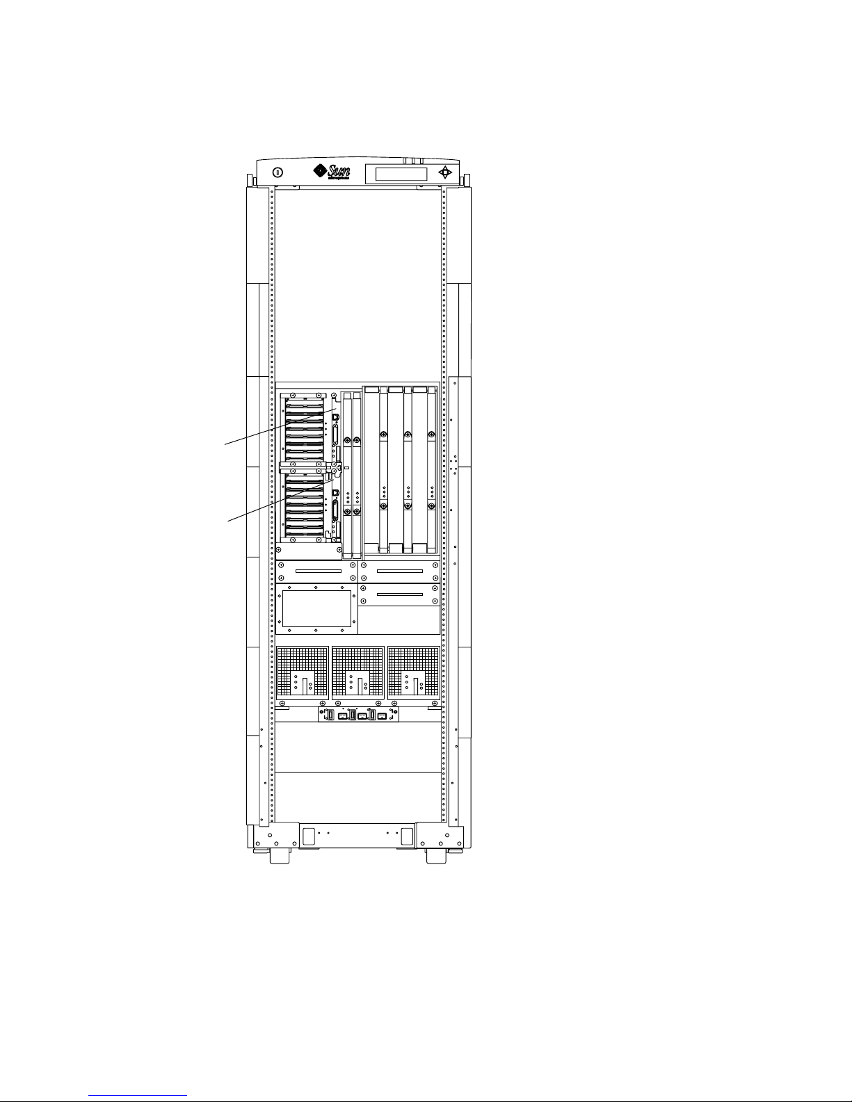
SSC1
SSC0
FIGURE 7-4 System Controller Board Slot Assignments for the Sun Fire 4810 System—
Front View
7-6 Sun Fire 6800/4810/4800/3800 Systems Service Manual • May 2008
Page 87

SSC1
SSC0
FIGURE 7-5 System Controller Board Slot Assignments for the Sun Fire 4800 System—
Rear View
Chapter 7 System Controller Board 7-7
Page 88

SSC1
SSC0
FIGURE 7-6 System Controller Board Slot Assignments for the Sun Fire 3800 System—
Front View
7.2.2 System Controller Board LEDs
There are three LEDs on the System Controller board. TABLE 7-2 notes the LED
functions.
TABLE 7-2 System Controller Board LED Functions
LED Name and Location On Off
Activated LED
(green)
Fault LED (amber) Internal fault
OK to remove LED
(amber)
7-8 Sun Fire 6800/4810/4800/3800 Systems Service Manual • May 2008
Board is activated
Assembly can be removed Assembly cannot be
Board is deactivated.
No internal fault
removed
Page 89

7.2.3 Resetting the System Controller Board
Caution – For all SC-App versions, resetting a System Controller should be an
absolute last resort, it is always preferable to try the reboot command first. For
System Controllers with firmware 5.11.x or 5.12.x versions, an attempt to reset the
board could bring down running domains. If the System Controller can not be
rebooted, it is safer to take all the domains down before attempting to reset it.
Note – System Controllers with firmware Versions 5.13.x and later have automatic
System Controller failover implemented for systems with two System Controllers.
The main System Controller puts out a clock signal which the spare System
Controller monitors. If the spare System Controller does not see a clock signal due
to a unresponsive main System Controller, it will automatically initiate a failover
and become the main System Controller only if failover has been enabled and is
active, otherwise you may risk domain crashes.
Caution – If a System Controller board is still unresponsive to commands after first
attempting to use the reboot command, take all the domains down before attempting
to use the reset switch located on the board itself.
● Press the Reset switch (FIGURE 7-7) by using a pen tip to reset the System
Controller board so that it reboots.
Pressing the reset switch reloads the system controller software.
Chapter 7 System Controller Board 7-9
Page 90

Reset
switch
FIGURE 7-7 Reset Switch on a System Controller Board
7.2.4 Replacing a System Controller Board
7.2.4.1 Removing the System Controller Board with Firmware 5.11.x
or 5.12.x
Caution – To avoid damaging internal circuits, do not disconnect or connect any
cable while power is applied to the system.
1. Complete the software procedures for preparing to remove the System Controller
board.
Refer to the Sun Fire Midrange Systems Platform Administration Manual, Chapter 9
“Removing and Replacing Boards.”
2. Power off the system.
Refer to the Sun Fire Midrange Systems Platform Administration Manual for complete
system procedures for powering off.
3. Attach a wrist strap or foot strap. Connect the ESD strap to the system. Place a
grounded ESD mat close to the system.
7-10 Sun Fire 6800/4810/4800/3800 Systems Service Manual • May 2008
Page 91

Caution – The system is sensitive to static electricity.
4. Disconnect the serial or network cable from the board.
5. Loosen the two captive screws (
FIGURE 7-8) on the System Controller board by
using a Phillips No. 2 screwdriver.
These screws are springloaded. They will pop out when completely unfastened.
6. Pull outward on the board ejectors to unseat the board (
FIGURE 7-8).
7.2.4.2 Removing the System Controller Board with Firmware 5.13.x
or Later Versions.
1. Complete the software procedures for preparing to remove the System Controller
board.
Refer to the Sun Fire Midrange Systems Platform Administration Manual, Chapter 9
“Removing and Replacing Boards.”
2. Attach a wrist strap or foot strap. Connect the ESD strap to the system. Place a
grounded ESD mat close to the system.
Caution – The system is sensitive to static electricity.
3. Disconnect the serial or network cable from the board.
4. Loosen the two captive screws (
FIGURE 7-8) on the System Controller board by
using a Phillips No. 2 screwdriver.
These screws are springloaded. They will pop out when completely unfastened.
5. Pull outward on the board ejectors to unseat the board (
Chapter 7 System Controller Board 7-11
FIGURE 7-8).
Page 92

Ejector lever
Captive screw
FIGURE 7-8 Loosening the Captive Screws and Ejector Levers
7-12 Sun Fire 6800/4810/4800/3800 Systems Service Manual • May 2008
Page 93
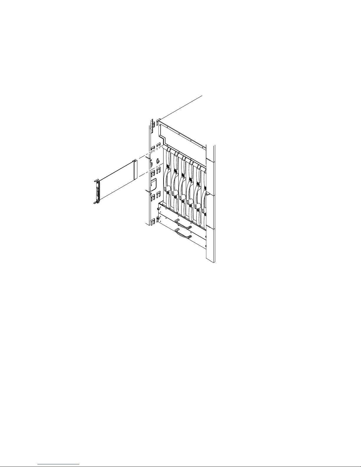
6. Slide the board out (FIGURE 7-9 and FIGURE 7-10).
FIGURE 7-9 illustrates how to install or remove the board for a Sun Fire 6800 system.
This is similar also to the Sun Fire 4810/4800 systems.
FIGURE 7-10 illustrates how to
install or remove the board for a Sun Fire 3800 system.
FIGURE 7-9 Removing and Replacing a System Controller Board—Sun Fire 6800 System
Chapter 7 System Controller Board 7-13
Page 94

FIGURE 7-10 Removing and Replacing a System Controller Board—Sun Fire 3800 System
7.2.4.3 Installing the System Controller Board
1. Power off the system.
Refer to the Sun Fire Midrange Systems Platform Administration Manual for complete
system procedures for powering off.
2. Attach a wrist strap or foot strap. Connect the ESD strap to the system. Place a
grounded ESD mat close to the system.
Caution – The system is sensitive to static electricity.
3. Turn both board ejectors outward before you insert the board into the card cage.
4. Line up the board with the slots.
■ For the Sun Fire 6800/4810/4800 systems, slide the board into the card cage slot
(
FIGURE 7-9).
■ For the Sun Fire 3800 system, put one hand on the center of the board and the
other hand on the front panel. Slide the board into the slot.
Caution – Do Not Force any board into a slot; this can cause damage to the board
and system. The board should insert and seat smoothly. If it binds, remove the board
and inspect the card cage slot for any obvious obstructions.
5. After the board is completely into the card cage, simultaneously push inward on
both board ejectors (
7-14 Sun Fire 6800/4810/4800/3800 Systems Service Manual • May 2008
FIGURE 7-11).
Page 95

6. Tighten the two captive screws using a Phillips No. 2 screwdriver (FIGURE 7-11).
Ejector lever
Captive screw
FIGURE 7-11 Tightening the Captive Screws and Locking the Ejector Levers
7. Connect the serial or network cable to the board.
8. Power on the system.
Refer to the Sun Fire Midrange Systems Platform Administration Manual for complete
system procedures for powering on.
Chapter 7 System Controller Board 7-15
Page 96

9. Complete the software procedures for installing the System Controller board.
Refer to the Sun Fire Midrange Systems Platform Administration Manual, Chapter 9
“Removing and Replacing Boards.”
7-16 Sun Fire 6800/4810/4800/3800 Systems Service Manual • May 2008
Page 97

CHAPTER
8
CPU/Memory Boards and
Components
To protect both yourself and the equipment, make sure you follow the precautions in
Chapter 1.
This chapter contains the following sections:
■ Section 8.1 “Handling Boards and Assemblies” on page 8-1
■ Section 8.2 “Filler Panels and Filler Boards” on page 8-3
■ Section 8.3 “CPU/Memory Boards” on page 8-3
■ Section 8.3.1 “Replacing CPU/Memory Boards” on page 8-7
■ Section 8.3.2 “Replacing DIMMs” on page 8-13
For your protection, also observe the following safety precautions when setting up
your equipment:
■ Follow all cautions, warnings, and instructions marked on the equipment.
■ Always use proper ESD equipment and procedures when handling boards and
components.
■ Never push objects of any kind through openings in the equipment as they may
touch dangerous voltage points or short out components that can result in fire or
electric shock.
■ Refer servicing of equipment to qualified personnel.
8.1 Handling Boards and Assemblies
Caution – The chassis AC power cord(s) must remain connected to ensure a proper
ground.
8-1
Page 98

Caution – The system is sensitive to static electricity. To prevent damage to the
board, connect an antistatic wrist strap between you and the system.
Caution – The CPU/Memory boards have surface-mount components that can be
broken if you flex the boards.
To minimize the amount of board flexing, observe the following precautions:
■ Hold the board only by the handle and by the edges near the middle of the board,
where the board stiffener is located. Do not hold the board only at the ends.
■ When removing the board from an antistatic bag, keep the board vertical until
you lay it on the ESD mat.
■ Do not place the board on a hard surface. Use a cushioned antistatic mat. The
board connectors and components have very thin pins that bend easily.
■ Be careful of small component parts located on both sides of the board.
■ Do not use an oscilloscope probe on the components. The soldered pins are easily
damaged or shorted by the probe point.
■ Transport the board in an antistatic bag.
Caution – The CPU/Memory board is heavy and weighs approximately 17 to 22
pounds (7.7 to 9.0 kg). Take care when removing the board from the system.
Caution – The heatsinks on the board can be damaged by incorrect handling. Do
not touch the heatsinks while replacing or removing the board. If a heatsink is loose
or broken, obtain a replacement board.
Caution – The heatsinks on the board can be damaged by improper packaging.
When storing or shipping the board, ensure that the heatsinks have sufficient
protection.
Note – The CPU/Memory board can be inserted into a powered-on system. The
board will not be recognized by the system until the domain has been dynamically
reconfigured to include the board or re-initialized and rebooted. Refer to Sun Fire
Midrange Systems Dynamic Reconfiguration User Guide for complete DR procedures or
the Sun Fire Midrange Systems Platform Administration Manual for complete
procedures for re-initializing a domain.
8-2 Sun Fire 6800/4810/4800/3800 Systems Service Manual • May 2008
Page 99

8.2 Filler Panels and Filler Boards
In order to prevent the system from overheating, see Section 1.4 “Filler Boards and
Filler Panels” on page 1-5 for procedures you must follow when removing CPU/
Memory boards from a system.
8.3 CPU/Memory Boards
All systems support the following:
■ Up to four CPU processors with each processor supporting two DIMM (dual
inline memory module) banks of four DIMMs per bank
■ Eight Ecache modules (two per CPU processor)
■ Up to 8 Gbytes of memory per CPU processor (CPU/Memory+ board only)
■ Up to 32 DIMMs
On the CPU/Memory board, the memory controller is integrated in the CPU
processor. The CPU/Memory board has a metal cover that covers the CPU
processors and Ecache.
CPU/Memory board types available are:
■ UltraSPARC® III 750-MHz processor—known as CPU/Memory board
■ UltraSPARC III+ (Cu) 900-MHz processor—known as CPU/Memory+ 900 board
■ UltraSPARC III+ (Cu) 1.05-GHz processor—known as CPU/Memory+ 1.05 board
■ UltraSPARC III+ (Cu) 1.2-GHz processor—known as CPU/Memory+ 1.2 board
There are three LEDs on the CPU/Memory board.
TABLE 8-1 CPU/Memory Board LED Functions
LED On Off
Activated LED
(green)
Fault LED (amber) Internal fault
OK to remove
(amber)
FIGURE 8-1 illustrates the CPU/Memory board LEDs and major components.
Device is activated.
Assembly can be removed Assembly cannot be
TABLE 8-1 notes the LED functions.
Device is deactivated
No internal fault
removed
Chapter 8 CPU/Memory Boards and Components 8-3
Page 100

10
1
9
2
3
8
67
4
5
FIGURE 8-1 CPU/Memory Board With the Cover Installed
Key Description
1
2
3
4
5
6
7
CPU processor 1 land area
CPU processor 0 land area
CPU processor 3 land area
CPU processor 2 land area
Ejector lever
Activated LED (green)
Fault LED (amber)
8
9
10
8-4 Sun Fire 6800/4810/4800/3800 Systems Service Manual • May 2008
OK to remove LED (amber)
Ejector lever
DIMMs
 Loading...