

Page 1

4-081-283-11(1)
24-Inch FD Premium (22.5-inch Viewable)
Color Monitor Guide
Operating Instructions Page 3
Before operating the unit, please read this manual thoroughly and
retain it for future reference.
Mode d'emploi Page 21
Avant la mise en service de cet appareil, prière de lire attentivement ce
mode d'emploi que l'on conservera pour toute référence ultérieure.
Bedienungsanleitung Seite 39
Lesen Sie vor der Inbetriebnahme diese Anleitung sorgfältig durch
und bewahren Sie sie zum späteren Nachschlagen gut auf.
Manual de instrucciones Página 57
Antes de utilizar la unidad, lea este manual detenidamente y
consérvelo para futuras referencias.
Istruzioni per l'uso Pagina 75
Prima di usare l'apparecchio, leggere con attenzione questo manuale e
conservarlo per riferimenti futuri.
Bruksanvisning Sid 93
Innan du använder monitorn bör du läsa igenom denna
bruksanvisning och sedan spara den för framtida behov.
取扱説明書 111ページ
お買い上げいただきありがとうございます。
お使いになる前に、この取扱説明書をお読みください。
お読みになった後は、後日お役に立つこともありますので、必ず保存
してください。
KR Page 133
Before operating the unit, please read this manual thoroughly and
retain it for future reference.
CS (Simple Chinese) Page 151
Before operating the unit, please read this manual thoroughly and
retain it for future reference.
CT (Traditional Chinese) Page 169
Before operating the unit, please read this manual thoroughly and
retain it for future reference.
Page 2
2
Owner’s Record
The model and serial numbers are located at the rear of the unit.
Record these numbers in the spaces provided below. Refer to them
whenever you call upon your dealer regarding this product.
Model No.
Serial No.
To prevent fire or shock hazard, do not expose the
unit to rain or moisture.
Dangerously high voltages are present inside the
unit. Do not open the cabinet. Refer servicing to
qualified personnel only.
FCC Notice
This equipment has been tested and found to comply with the limits
for a Class B digital device, pursuant to Part 15 of the FCC Rules.
These limits are designed to provide reasonable protection against
harmful interference in a residential installation. This equipment
generates, uses, and can radiate radio frequency energy and, if not
installed and used in accordance with the instructions, may cause
harmful interference to radio communications. However, there is no
guarantee that interference will not occur in a particular installation.
If this equipment does cause harmful interference to radio or
television reception, which can be determined by turning the
equipment off and on, the user is encouraged to try to correct the
interference by one or more of the following measures:
– Reorient or relocate the receiving antenna.
– Increase the separation between the equipment and receiver.
– Connect the equipment into an outlet on a circuit different from
that to which the receiver is connected.
– Consult the dealer or an experi enced radi o/TV techni cian for hel p.
You are cautioned that any changes or modifications not expressly
approved in this manual could void your authority to operate this
equipment.
INFORMATION
This product complies with Swedish National Council for Metrology
(MPR) standards issued in December 1990 (MPR II) for very low
frequency (VLF) and extremely low frequency (ELF).
INFORMATION
Ce produit est conforme aux normes du Swedish National Council
for Metrology de décembre 1990 (MPR II) en ce qui concerne les
fréquences très basses (VLF) et extrêmement basses (ELF).
INFORMACIÓN
Este producto cumple las normas del Consejo Nacional Sueco para
Metrología (MPR) emitidas en diciembre de 1990 (MPR II) para
frecuencias muy baj as (VLF) y frecu enci as extr emada mente ba jas (E LF).
Production Model name: GDM-FW9010 (22.5” viewing image)
WARNING
Declaration of Conformity
Trade Name: Sun Microsystems, Inc.
Model No.: GDM-FW9010
Responsible Party: Sun Microsystems, Inc.
Address: 901 San Antonio Rd. MPK15-102
Palo Alto, Ca 940303-4900, USA
Telephone No.: 650-786-3255
This device complies with Part 15 of the FCC Rules. Operation is
subject to the following two conditions: (1) This device may not
cause harmful interference, and (2) this device must accept any
interference received, including interference that may cause
undesired operation.
NOTICE
This notice is applicable for USA/Canada only.
If shipped to USA/Canada, install only a UL LISTED/CSA
LABELLED power supply cord meeting the following
specifications:
SPECIFICATIONS
Plug Type Nema-Plug 5-15p
Cord Type SVT or SJT, minimum 3 × 18 AWG
Length Maximum 15 feet
Rating Minimum 7 A, 125 V
NOTICE
Cette notice s’applique aux Etats-Unis et au Canada
uniquement.
Si cet appareil est export* aux Etats-Unis ou au Canada, utiliser
le cordon d’alimentation portant la mention UL LISTED/CSA
LABELLED et remplissant les conditions suivantes:
SPECIFICATIONS
Type de fiche Fiche Nema 5-15 broches
Cordon Type SVT ou SJT, minimum 3 × 18 AWG
Longueur Maximum 15 pieds
Tension Minimum 7 A, 125 V
As an
E
NERGY STAR Partner, Sun
Microsystems, Inc. has determined
that this product meets the
E
NERGY
S
TAR guidelines for energy
efficiency.
This monitor complies with the
TCO’99 guidelines.
Page 3
3
Table of Contents
• Trinitron is a registered trademark of
Sony Corporation.
• VESA and DDC
are trademarks of the
Video Electronics Standard
Association.
•
E
NERGY STAR is a U.S. registered
mark.
• All other product names ment i one d
herein may be the trademarks or
registered trademarks of their respective
companies.
• Furthermore, “” and “” are not
mentioned in each case in this manual.
GB
Precautions. . . . . . . . . . . . . . . . . . . . . . . . . . . . . . . . . . . . . . . . . . . 4
Identifying parts and controls . . . . . . . . . . . . . . . . . . . . . . . . . . . . . 5
Setup. . . . . . . . . . . . . . . . . . . . . . . . . . . . . . . . . . . . . . . . . 7
Step 1:
Connect your monitor to your computer . . . . . . . . . . . . . . 7
Step 2:
Connect the power cord. . . . . . . . . . . . . . . . . . . . . . . . . . . 7
Step 3:
Turn on the monitor and computer . . . . . . . . . . . . . . . . . . 7
Connecting Universal Serial Bus (USB) compliant peripherals . . . 8
Selecting the on-screen menu language (LANG). . . . . . . . . . . . . . 8
Selecting the input signal . . . . . . . . . . . . . . . . . . . . . . . . . . . . . . . . 9
Automatically sizing and centering the picture (AUTO) . . . . . . . . . 9
Customizing Your Monitor . . . . . . . . . . . . . . . . . . . . . . 10
Navigating the menu. . . . . . . . . . . . . . . . . . . . . . . . . . . . . . . . . . . 10
Adjusting the brightness and contrast. . . . . . . . . . . . . . . . . . . . . . 11
Adjusting the centering of the picture (CENTER) . . . . . . . . . . . . . 12
Adjusting the size of the picture (SIZE) . . . . . . . . . . . . . . . . . . . . 12
Enlarging or reducing the picture (ZOOM) . . . . . . . . . . . . . . . . . . 12
Adjusting the shape of the picture (GEOM) . . . . . . . . . . . . . . . . . 12
Adjusting the color of the picture (COLOR) . . . . . . . . . . . . . . . . . 12
Adjusting the quality of the picture (SCREEN) . . . . . . . . . . . . . . . 14
Adjusting the convergence (CONV) . . . . . . . . . . . . . . . . . . . . . . . 15
Additional settings (OPTION) . . . . . . . . . . . . . . . . . . . . . . . . . . . . 15
Resetting the adjustments . . . . . . . . . . . . . . . . . . . . . . . . . . . . . . 16
Technical Features . . . . . . . . . . . . . . . . . . . . . . . . . . . . 16
Preset and user modes. . . . . . . . . . . . . . . . . . . . . . . . . . . . . . . . . 16
Power saving function. . . . . . . . . . . . . . . . . . . . . . . . . . . . . . . . . . 16
Troubleshooting. . . . . . . . . . . . . . . . . . . . . . . . . . . . . . . 17
If thin lines appear on your screen (damper wires). . . . . . . . . . . . 17
On-screen messages . . . . . . . . . . . . . . . . . . . . . . . . . . . . . . . . . . 17
Trouble symptoms and remedies . . . . . . . . . . . . . . . . . . . . . . . . . 18
Self-diagnosis function . . . . . . . . . . . . . . . . . . . . . . . . . . . . . . . . . 20
Specifications. . . . . . . . . . . . . . . . . . . . . . . . . . . . . . . . . 20
Appendix. . . . . . . . . . . . . . . . . . . . . . . . . . . . . . . . . . . . . . . i
TCO’99 Eco-document . . . . . . . . . . . . . . . . . . . . . . . . . . . . . . . . . . . .i
Page 4
4
Precautions
Warning on power connections
Use an appropriate power cord for your local power supply.
• Before disconnecting the power cord, wait at least 30 seconds
after turning off the power to allow the static elec tricity on the
screen’s surface to discharge.
• After the power is turned on, the screen is demagnetized
(degaussed) for about 3 seconds. This generates a strong
magnetic field around the screen which may affect data stored
on magnetic tapes and disks placed near the monitor. Be sure to
keep magnetic recording equipment, tapes, and disks away
from the monitor.
Installation
Do not install the monitor in the following pl aces:
• on surfaces (rugs, blankets, etc.) or near materials (curtains,
draperies, etc.) that may block the ventilation holes
• near heat sources such as radiators or air ducts, or in a place
subject to direct sunlight
• in a place subject to severe temperature changes
• in a place subject to mechanical vibration or shock
• on an unstable surface
• near equipment which generates magnetism, such as a
transformer or high voltage po wer lines
• near or on an electrically charged metal surface
Maintenance
• Clean the screen with a soft cloth. If you use a glass clean ing
liquid, do not use any type of cleaner containing an anti-static
solution or similar additive as this may scratch the screen’s
coating.
• Do not rub, touch, or tap the surface of the screen with sharp or
abrasive items such as a ballpoint pen or screwdriver. This type
of contact may result in a scratched picture tube.
• Clean the cabinet, panel and controls with a soft cloth lightly
moistened with a mild detergent solu tion. Do not use any type
of abrasive pad, scouring powder or solvent, such as alcohol or
benzene.
Transportation
When you transport this monitor for repair or shipment, use the
original carton and packing materials.
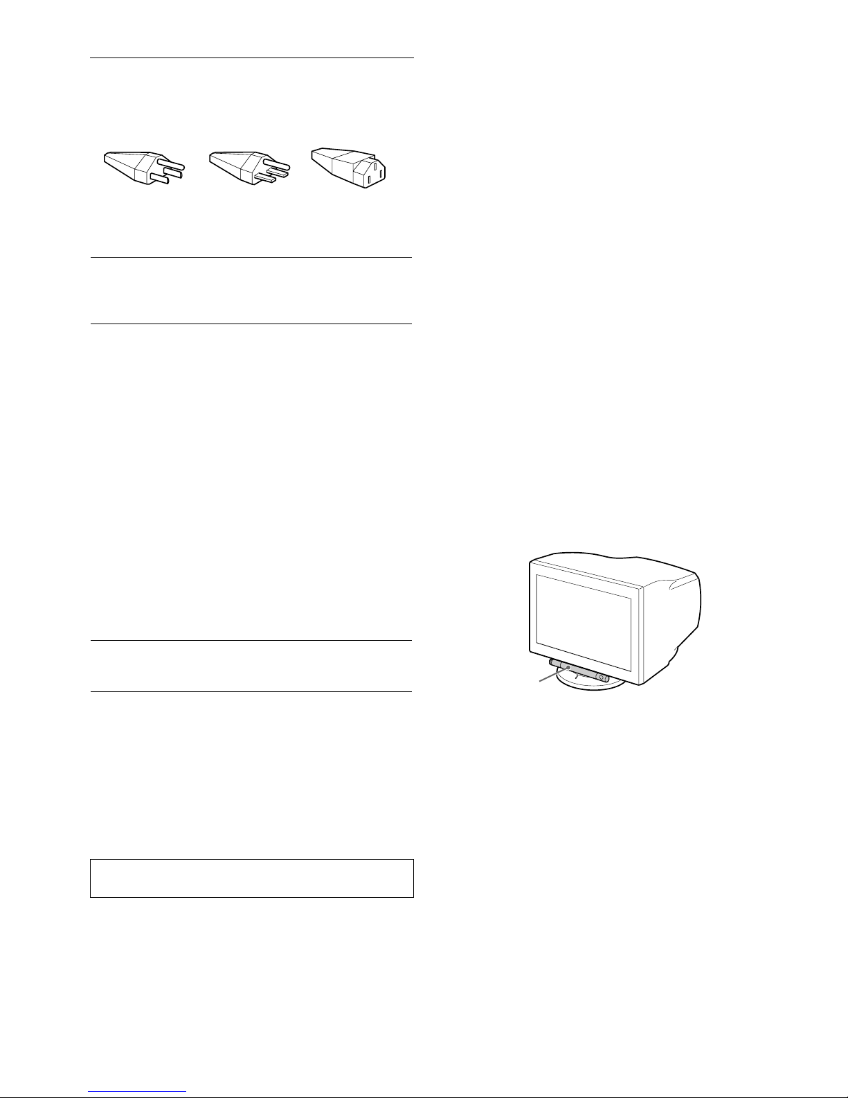
Never grasp the control bar when you transport the
monitor.
United States,
Canada,
Taiwan,
Korea, Japan
Continental
Europe
United
Kingdom,
Ireland
Australia,
New Zealand
Plug Type
NEMA S-15P
Plug Type
CEE7/VII
(Schuko)
Plug Type
B S 1363
Plug Type
SAA AS 3112
Cord Type
SJT
Cord Type
HAR(HO5VV
-F3G1.0)
Cord Type
HAR(HO5VV
-F3G1.0)
Cord Type
CDB03PLP
Min. cord set
rating
10 A/125 V
18/3AWG
Min. cord set
rating
10 A/250 V
Min. cord set
rating
10 A/250 V
Min. cord set
rating
10 A/250 V
Cord Length
(+/– 0.1 m)
2 m
Cord Length
(+/– 0.1 m)
2.5 m
Cord Length
(+/– 0.1 m)
2.5 m
Cord Length
(+/– 0.1 m)
2.5 m
Safety
Approval
UL/CSA
Safety
Approval
HAR
Safety
Approval
BSI, ASTA
Safety
Approval
Dept. of
Energy of
New South
Wales
Autoranging universal power supply works anywhere; the
monitor self-adjusts if the appropriate power cord and plug for
the local voltage are used.
The equipment should be in stalled near an easily accessible
outlet.
115 Volts 230 Volts
(not provided on
standard cord set)
CEE-22 cord set,
female end (all
power cord sets)
Control bar
Page 5
5
GB
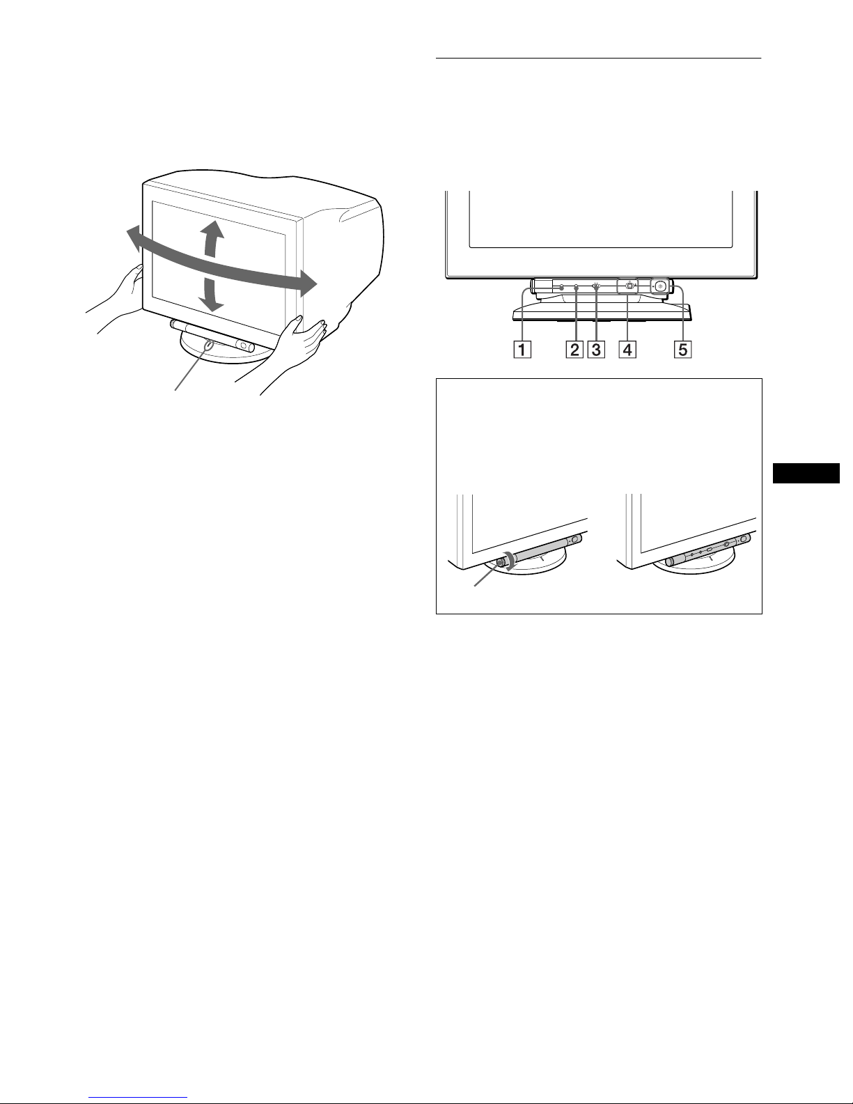
Use of the tilt-swivel
This monitor can be adjusted withi n th e an gles sho wn b e low. To
find the center of the monitor’s turn ing rad ius, al ign the ce nter of
the monitor’s screen with the centering dots on the stand .
Hold the monitor at the bo tto m wit h b oth ha n ds when yo u t urn it
horizontally or vertically.
Identifying parts and controls
See the pages in parentheses or further details.
1
RESET (reset) button (page 16)
This button resets the adjustments to the factory settings.
2222
ASC (auto sizing and centering) button (page 9)
This button automatically adjusts the size and centerin g of the
picture.
3333
INPUT (input) switch (page 9)
This switch selects the 13W3 or HD15 video input signal.
4444
Joystick (page 11)
The joystick is used to display the menu and make
adjustments to the monitor, including brightness and contrast
adjustmen ts .
5555 !
(power) switch and indicator (pages 7, 16, 20)
This button turns the monitor on and off. The power indicator
lights up in green when the monitor is turned on, and either
flashes in green and orange, or lights up in orange when the
monitor is in power saving mode.
165°
5°
165°
15°
Centering dots
To use the control bar
This monitor has a cylindrical swivel control bar. To operate the
controls, turn the knob on the left side downward to expose the control
buttons. When the control buttons are not needed, turn the knob up to
hide the control bu ttons.
When not using When using
MENU
INPUTASCRESET 21
Front
,
Knob
(continued)
Page 6
6
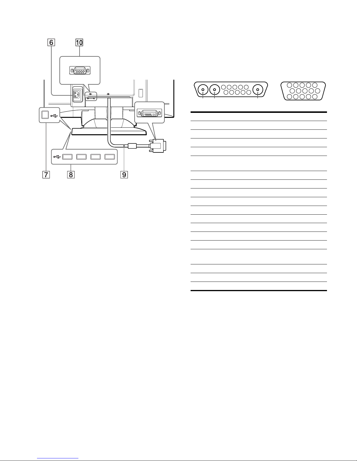
6666
AC IN connector (page 7)
This connector provides AC power to the monitor.
7777
USB (universal serial bus) upstream connector
(page 8)
Use this connector to link the monitor to a USB compliant
computer.
8888
USB (universal serial bus) downstream connectors
(page 8)
Use these connectors to link USB peripheral devices to the
monitor.
9999
Video input 1 connector (13W3) (page 7)
This connector inputs RGB video signals (0.700 Vp-p,
positive) and sync signals.
q;
q;q;
q;
Video input 2 connector (HD15) (page 7)
This connector inputs RGB video signals (0.700 Vp-p,
positive) and sync signals.
* DDC (Disp lay Dat a C hannel) is a standard of VESA.
**Pins serve a dual purpose as combined sync input and as H.sync input
if V.Sync is present on pin no. 7.
AC IN
2 1
Rear
forward side
rear side
No.
9999
Signal
0000
Signal
A1 Red –––
A2 Green –––
A3 Blue –––
1 Data Clock (SCL)* Red
2 DDC + 5V* Green
(Composite Sync on Green)
3 ––– Blue
4 DDC Ground* ID (Ground)
5 C Sync** DDC Ground*
6 Bi-Directional Data (SDA)* Red Ground
7 V. Sync Green Ground
8ID (100Ω) Blue Ground
9ID (100Ω)DDC + 5V*
10 Ground Ground
11 ––– ID (Ground)
12 ––– Bi-Directional Data
(SDA)*
13 ––– H. Sync
14 ––– V. Sync
15 ––– Data Clock (SCL)*
5 4 3 2
1
678910
11A312131415
5 4 3 2
1
678910
A2 A1
9
13W3
0
HD15
Page 7

7
GB
Setup
This monitor works with platforms running at horizontal
frequencies between 30 and 121 kHz.
Step 1:Connect your monitor to
your computer
Turn off the monitor and computer b efore connecting.
Notes
• Do not touch the pins of the video signal cable connector as this might
bend the pins.
• When connecting the video signal ca b le , check the alignment of the
connector. Do not force the connector in the wrong way or the pins
might bend.
xxxx
Connecting to the 13W3 connector
xxxx
Connecting to the HD15 connector
Step 2:Connect the power cord
With the monitor and computer switc hed off, first connect the
power cord to the monitor, then connect it to a power outlet.
Step 3:Turn on the monitor and
computer
First turn on the monitor, then turn on the computer.
The installation of your monitor is complete.
If necessary, use the monitor’s controls to adjust the picture.
If no picture appears on your screen
• Check that the monitor is correctly connected to the computer.
• If NO INPUT SIGNAL appears on the screen, try changing the
input signal (page 9), and confirm that your computer’s graphic
board is completely seated in the correct bus slot.
• If you are replacing an old monitor with this model and OUT
OF SCAN RANGE appears on the screen, reconnect the old
monitor. Then adjust the computer’s graphic board so that the
horizontal frequency is between 30 – 121 kHz, and the vertical
frequency is between 48 – 160 Hz.
For more information about the on-screen messages, see “Trouble
symptoms and remedi es” on page 18.
AC IN
2 1
To a computer with
a 13W3 video output
AC IN
2 1
To a computer with
an HD15 video output
AC IN
2 1
to AC IN
to a power outlet
power cord
Page 8

8
Connecting Universal Serial Bus
(USB) compliant peripherals
Your monitor has one upstream and four downstream USB
connectors. They provide a fas t an d easy way to connect USB
compliant peripheral devices (such as keyboards, mice, printers
and scanners) to your computer using a standardized USB cable.
To use your monitor as a hub for your peripheral devices, connect
the USBs as illustrated below.
1
Turn on the monitor and computer.
2
Connect your computer to the square up stream
connector using the USB cable (supplied).
3
Connect your USB compliant peripheral devices to
the rectangular downstream USB connectors.
Notes
• Not all computers and/ or operating systems suppor t USB
configurations. Check your computer’s instruction manual to see if you
can connect USB devices.
• In most cases, USB driver softw are needs to be installed on the host
computer. Refer to the peripheral device’s instruction manual for
further details.
• The monitor functions as a USB hub as long as the monitor is either
“on” or in power saving mode.
• If you connect a keybo ard or mouse to the USB connectors and then
boot your computer for the first time, the peripheral devices may not
function. First connect the keyboard and mouse directly to the
computer and set up the USB compliant devices. Then connect them to
this monitor.
Selecting the on-screen menu
language (LANG)
English, French, German, Spanish, Italian, Dutch, Swedish,
Russian and Japanese versions of the on-screen menus are
available. The default setting is English.
1
Press the joystick.
See page 11 for more information on using the joystick.
2
Move the joystick to highlight LANG and press
the joystick again.
3
Move the joystick up or down to select a language
and press the joystick again.
• ENGLISH
• FRANÇAIS: French
• DEUTSCH: German
• ESPAÑOL: Spanish
• ITALIANO: Italian
• NEDERLANDS: Dutch
• SVENSKA: Swedish
• : Russian
• : Japanese
To close the menu
Press the joystick on ce to return to the main menu, and twice to retur n to
normal viewing. If no buttons are pressed, the menu closes automatically
after about 30 seconds.
To reset to English
Press the RESET button while the LANGUAGE menu is displayed on the
screen.
to USB compliant
peripheral devices
to a USB compliant
computer
MENU
MENU
EXIT
CENTER
SIZE
GEOM
SCREEN
COLOR
LANG
CONV
OPTION
OK
b
ENGL ISH
FRANÇA I S
DEUTSCH
ESPAÑOL
ITAL IANO
NEDERLANDS
SVENSKA
LANGUAGE
bb
Page 9

9
GB
Selecting the input signal
You can connect two computers to this monitor using the video
input 1 (13W3) and video input 2 (HD15) connectors. To switch
between the two computers, use the
INPUT
switch.
Move the INPUT switch.
The currently selected connect or (“INPU T 1” : 13W3 or
“INPUT 2” : HD15) appears on the screen for a few seconds.
Note
If no signal is input to the selected connector, NO INPUT SIGNAL
appears on the screen. After a few seconds, the monitor enters the power
saving mode.
Automatically sizing and centering
the picture (AUTO)
You can easily adjust the picture to fill the screen by pressing the
ASC (auto sizing and centering) button.
Press the ASC button.
The picture automatically fills the screen.
Notes
• This function is intended for use with a computer tha t provides a fullscreen picture. It may not work properly if the background color is dark
or if the input picture do es not fil l the screen to the edges.
• The picture will fill the screen to the edges only if the aspect ratio of the
picture is 16:10. Pictures with an asp ec t ra ti o ot her than 16:10 are
displayed at thei r actual resolutio n and do not fill the scree n to the
edges.
• The displayed image moves for a few se c onds while this function is
performed. This is not a malfunction.
INPUT 21
ASC
Page 10

10
Customizing Your Monitor
You can make numerous adj ustments to your monito r u s ing the
on-screen menu.
Navigating the menu
Press the joystick to display the main M ENU on your screen. See
page 11 for more information on using the joystick.
Use the joystick to select one of the following menus.
xxxx
Displaying the current input signal
The horizontal and vertical frequencies of the current input signal
are displayed un der the m ain MENU. I f the signa l matches on e of
this monitor’s factory preset modes, the resolution is also
displayed.
Note
In some cases, even though the aspect ratio of the current input signal is
4:3 or 5:4, the resoluti on m ay be displayed with an aspect rati o of 16:10
or 16:9.
1
CENTER (page 12)
Select the CENTER menu
to adjust the picture’s
centering or zoom.
2
SIZE (page 12)
Select the SIZE menu to
adjust the picture’s size or
zoom.
3333
GEOM (page 12)
Select the GEOM menu to adjust the
picture’s rotation and shape.
4444
COLOR (page 12)
Select the COLOR menu to
adjust the picture’s color
temperature. You can use
this to match the monitor’s
colors to a printed picture’s
colors.
5555
SCREEN (page 14)
Select the SCREEN menu to adjust
the picture’s quality. You can adjust
the landing and moire cancellation
effect.
MENU
MENU
EXIT
CENTER
SIZE
GEOM
SCREEN
COLOR
LANG
CONV
OPTION
OK
b
26
SI ZE / CENTER
26
SI ZE / CENTER
26
GEOMETRY
EASY EXPERT s BGR
5000K 6500K 930 K0
50 K00
IMAGE
RESTORAT I ON ON
COLOR
LANDING
26
SCREEN
6666
CONV (page 15)
Select the CONV menu to adjust the
picture’s horizontal and vertical
convergence.
7777
LANG (page 8)
Select the LANG menu to choose
the on-screen menu’s languag e.
8888
OPTION (page 15)
Select the OPTION menu to adjust
the monitor’s options. The options
include:
• degaussing the screen
• changing the on-screen menu
position
• locking the controls
9999
EXIT
Select EXIT to close the menu.
TOP
BOT
26
CONVERGENCE
ENGL ISH
FRANÇA I S
DEUTSCH
ESPAÑOL
ITALIANO
NEDERL ANDS
SVENSKA
LANGUAGE
DEGAUSS
ON
OPT ION
MENU
MENU
EXIT
CENTER
SIZE
GEOM
SCREEN
COLOR
LANG
CONV
OPTION
OK
107.1kHz/ 85Hz
1920
1200
the horizontal
and vertical
frequencies of
the current
input signal
the resolution
of the current
input signal
Page 11

11
GB
x
Using the joystick
1
Display the main MENU and select the menu you
want to adjust.
Press the joystick once to display the main MENU. Then
move the joystic k up, down, left, or r ight to highlight the
desired menu. Press the joystick to select the menu item.
2
Adjust the menu.
Move the joystick up, down, left, or right to make the
adjustment.
3
Close the menu.
Press the joystick once to ret urn to t he ma in me nu , a nd twice
to return to normal viewing. If no bu ttons are pressed, the
menu closes automatical ly after about 30 seconds.
x
Resetting the adjustments
Press the RESET button. See page 16 for more information on
resetting the adjustments.
Adjusting the brightness and
contrast
Brightness and contrast adjust ments are made using a separate
BRIGHTNESS/CONTRAST menu.
These settings are stored in memory for the signals from the
currently selected input connector.
1
Move the joystick in any direction.
The BRIGHTNESS/CONTRAST menu appears on the
screen.
2
Move the joystick up or down to adjust the
brightness ( ), and left or right to adjust the
contrast (6).
If you select the sRGB mode in the COLOR menu
Confirm that the brightness ( ) and contrast (6) values are
adjusted respectively to the numbers to b e set in the sRGB mode
shown in the BRIGHTNESS/CONTRAST menu. If not, press the
RESET button (for less than 2 seconds).
For more information about using the sRGB mode, se e
“Adjusting the color of the pict ure (COLOR)” on page 12.
The menu automatically disappears after about 3 seconds.
bb
RESET
26 26
BR I GHTNESS / CONTRAST
56 76
sRGB : 56 76
BR I GHTNESS / CONTRAST
Values to be set
in the sRGB
mode
Page 12

12
Adjusting the centering of the
picture (CENTER)
This setting is stored in memory for the current input signal.
1
Press the joystick.
The main MENU appears on the screen .
2
Move the joystick to highlight CENTER and
press the joystick again.
The SIZE/CENTER menu appears on the screen.
3
First move the joystick up or down to select for
horizontal adjustment, or for vertical adjustment.
Then move the joystick left or right to adjust the
centering.
Adjusting the size of the picture
(SIZE)
This setting is stored in memory for the current input signal.
1
Press the joystick.
The main MENU appears on the screen .
2
Move the joystick to highlight SIZE and press the
joystick again.
The SIZE/CENTER menu appears on the screen.
3
First move the joystick up or down to select for
horizontal adjustment, or for vertical
adjustment. Then move the joystick left or right to
adjust the size.
Enlarging or reducing the picture
(ZOOM)
This setting is stored in memory for the current input signal.
1
Press the joystick.
The main MENU appears on the screen .
2
Move the joystick to highlight SIZE or
CENTER and press the joystick again.
The SIZE/CENTER menu appears on the screen.
3
Move the joystick up or down to select (zoom),
and move the joystick left or right to enlarge or
reduce the picture.
Note
Adjustment stops when either the horizontal or vertical size reaches its
maximum or minimum value.
Adjusting the shape of the picture
(GEOM)
The (rotation) setting is stor ed in memory for all input signals.
All other settings are stored in memory for the current input
signal.
1
Press the joystick.
The main MENU appears on the screen.
2
Move the joystick to highlight GEOM and press
the joystick again.
The GEOMETRY menu appears on the screen.
3
First move the joystick up or down to select the
desired adjustment item. Then mo ve the joystick left
or right to make the adjustment.
Adjusting the color of the picture
(COLOR)
The COLOR settings allow you to adjust the picture’s color
temperature by changing the color level of the white color field.
Colors appear reddish if the temperature is low, and bluish if the
temperature is high. This adjustment is useful for matching the
monitor’s color to a printed picture’s colors.
1
Press the joystick.
The main MENU appears on the screen.
2
Move the joystick to highlight COLOR and press
the joystick again.
The COLOR menu appears on the screen.
3
Move the joystick left or right to select the
adjustment mode.
There are three types of adjustment modes, EASY, EXPERT,
and sRGB.
Adjust the selected mode according to the instructions on the
next page.
You can set the color temperature in EASY or EXPERT mode
for each of the video input connectors.
Select To
rotate the picture
expand or contract the picture sides
shift the picture sides to the left or right
adjust the picture width at the top of the screen
shift the picture to the left or rig ht at the top of the
screen
Page 13

13
GB
x
EASY mode
In EASY mode, you can fine tune the color temperature by
changing the three preset te mperatures — 5000K, 6500K, or
9300K.
1
Move the joystick up or down to select the color
temperature row 1. Then move the joystick left or
right to select a color temperature.
The preset color temperatures are 5000K, 6500K, and 9300K.
The default setting is 9300K. The whites will change from a
bluish hue to a reddish hue as the temperature is lowered to
6500K and 5000K.
2
If necessary, fine tune the color temperature.
Move the joystick up or down to select the color
temperature row 2. Then move the joystick left or
right to fine tune the color temperature.
If you fine tune the color temperatu re , the new co lor settin g s
are stored in memory for each of the three color temperatures
and item 1 of the on-s cr e e n me nu changes as f ol lows.
• [5000K]t[1]
• [6500K]t[2]
• [9300K]t[3]
x
EXPERT mode
You can make addition al adjustments to the color in g reater detail
by selecting the EXPERT mode.
1
Move the joystick up or down to select the color
temperature row 1. Then move the joystick left or
right to select a color temperature.
2
Move the joystick up or down to select the
adjustment item 2. Then move joystick l eft or righ t
to adjust the BIAS (black level).
This adjusts the dark areas of an image.
3
Move the joystick up or down to select the
adjustment item 3. Then move the joystick left or
right to adjust the GAIN (white level).
This adjusts the light areas of an image.
You can adjust the R (red), G (green), B (blue) component of
the input signal when making changes to items 2 and 3.
If you fine tune the color temperatu re , the new co lo r setting s
are stored in memory for each of the three color temperatures
and item 1 of the on-s cr e e n me nu change as fol lows.
• [5000K]t[1]
• [6500K]t[2]
• [9300K]t[3]
x
sRGB mode
The sRGB color setting is an industry standard color space
protocol designed to correlate the displayed and printed colors of
sRGB compliant computer products. To adjust the colors to the
sRGB profile, simply select the sRGB mode in the COLOR menu.
Once you select the sRGB mode, the brightness ( ) and
contrast (6) values are automatic ally set to the v alues to be set in
the sRGB mode.
In order to display the sRGB colors correctly (γ = 2.2, 6500K),
confirm that:
• the brightness ( ) and contrast (6) values are ad j u sted
respectively to the numbers shown in the BRIGHTNESS/
CONTRAST menu. If not, press the RESET button (for less
than 2 seconds). For information on how to change the
brightness and contrast, see “Adjusting the brightness and
contrast” on page 11.
• the color settings of your computer are set to t he sRGB p rofile.
Note
Your computer and other connected products (such as a printer), must be
sRGB comp li ant.
EASY EXPERT s BGR
5000K 6500K 930 K0
50 K00
IMAGE
RESTORAT I ON ON
COLOR
EASY EXPERT s BGR
5000K 6500K 930 K0
R BIAS 05
G BIAS 05
B BIAS 05
RGAIN 05
GGAIN 05
BGAIN 05
COLOR
EASY EXPERT s BGR
:56 :76 FOR s BGR
IMAGE
RESTORAT I ON ON
COLOR
(continued)
Page 14

14
Restoring the color from the EASY or sRGB menus
(IMAGE RESTORATION function)
The colors of most display monitors tend to gradually lose brilliance
over several years of service. The IMAGE RESTORATION feature
found in the EASY and sRGB menus allows you to restore the color
to the original factory quality levels.
1
Move the joystick left or right to select EASY or
sRGB mode.
2
First move the joystick up or down to select
(IMAGE RESTORATION). Then move the
joystick to the right.
The picture disappears while th e color is being restored (about
2 seconds). After the color is restored, the pict ure reappears
on the screen again.
Notes
• Before using this feature , the monitor must be in normal opera ti on
mode (green power indicator on) for at least 30 minutes. If the monitor
goes into power saving mode, you m ust ret urn t he monitor to normal
operation mode and wa it for 30 minutes for the monitor to be re ady.
You may need to adjust your computer’s power saving settings to keep
the monitor in normal ope ration mode for the full 30 minu tes. If the
monitor is not ready, the following message will appea r.
• The monitor may gradually lose its ability to perform this function due
to the natural aging of the pic ture tube.
Adjusting the quality of the picture
(SCREEN)
The SCREEN settings allow you to adjust the quality of the
picture by controlling the moire and landing.
• If the color is irregul ar at the corners of the screen, adjust the
landing.
• If elliptical or wavy patterns appear on the screen, cancel the
moire.
The CANCEL MOIRE and MOIRE ADJUST settings are stored
in memory for the current input signal. All other settings are
stored in memory for all input signals.
1
Press the joystick.
The main MENU appears on the screen.
2
Move the joystick to highlight SCREEN and
press the joystick again.
The SCREEN menu appears on the scre en.
3
First move the joystick up or down to select the
desired adjustment item. Then mo ve the joystick left
or right to make the adjustment.
* Moire is a type of natural interference which produces soft, wavy lines
on your screen. It may appear due to interferenc e between the pattern
of the picture on the screen and the phosphor pitch pattern of the
monitor.
Note
The picture may become fuzzy when CANCEL MOIRE is set to ON.
EASY EXPERT s BGR
5000K 6500K 930 K0
50 K00
IMAGE
RESTORAT I ON
AVA I L ABL E
AFTER WARM UP
COLOR
Select To
LANDING
reduce any color irregularities in the
screen’s top left corner to a minimum.
LANDING
reduce any color irregularities in the
screen’s top rig ht corner to a
minimum.
LANDING
reduce any color irregularities in the
screen’s bott om left corn er to a
minimum.
LANDING
reduce any color irregularities in the
screen’s bottom right corner to a
minimum.
CANCEL MOIRE
*
turn the moire cancellation function
ON or OFF.
(MOIRE ADJUST) appears in
the menu when you select ON.
MOIRE ADJUST
adjust the degree of moire
cancellation until the moire is at a
minimum.
Example of moire
Page 15

15
GB
Adjusting the convergence (CONV)
The CONV settings allow yo u t o a d just the q ua lit y o f th e pi ctur e
by controlling the converg ence. The convergence refers to the
alignment of the r ed, green, and blue col or signals.
If you see red or blue shadows around letters or lines, adjust the
convergence.
These settings are stored in memory for all input signals.
1
Press the joystick.
The main MENU appears on the screen.
2
Move the joystick to highlight CONV and press
the joystick again.
The CONVERGENCE menu appears on the screen.
3
First move the joystick up or down to select the
desired adjustment item. Then m ove the joystick left
or right to make the adjustment.
Additional settings (OPTION)
You can manually degauss (demagnetize) the monitor, change the
menu position, and lock the controls.
1
Press the joystick.
The main MENU appears on the screen .
2
Move the joystick to high light OPT ION and press
the joystick again.
The OPTION menu appears on the screen.
3
Move the joystick up or down to select the desired
adjustment item.
Adjust the selected item according to the following
instructions.
xxxx
Degaussing the screen
The monitor is automaticall y demagnetized (deg aussed) when the
power is turned on.
To manually degauss the monitor, first move the
joystick up or down to select (DEGAUSS). Then
move the joystick to the right.
The screen is degaussed for about 3 seconds. If a second degauss
cycle is needed, allow a minimum interval of 20 minutes for the
best result.
xxxx
Changing the menu’ s position
Change the menu’s position if it is blocking an image on the
screen.
To change the menu’s on-screen position, first move
the joystick up or down to select (OSD H POSITION)
for horizontal adjustment, or (OSD V POSITION) for
vertical adjustment. Then move the joys tick left or right
to shift the on-screen menu.
xxxx
Lockin g the controls
To protect adjustment data by locking the cont rols, first
move the joystick up or down to select (CONTROL
LOCK). Then move the joystick to the right, to select
ON.
Only the ! (power) switch, EXIT, and (CONTROL LOCK)
of the OPTION menu will operate. If any other items are
selected, the mark appears on the screen.
To cancel the control lock
Repeat the procedure above and set (CONTROL LOCK) to OFF.
Select To
horizontally shift red or blue shadows
vertically shift red or blue shadows
TOP
V CONVER TOP
vertically shift red or blue shado ws at
the top of the screen
BOT
V CONVER
BOTT OM
vertically shift red or blue shado ws at
the bottom of the screen
Page 16

16
Resetting the adjustments
This monitor has the following three reset methods. Use the
RESET button to reset the adjustments.
xxxx
Resetting a single adjustment item
Use the joystick to select the ad justment item you want to reset,
and press the RESET button.
xxxx
Resetting all of the adjustment da ta for the
current input signal
Press the RESET button when no menu is disp layed on the scre en.
Note that the following items are not reset by this method:
• on-screen menu language (page 8)
• adjustment mode in the COLOR menu (EASY, EXPERT,
sRGB) (page 12)
• on-screen menu position (page 15)
• control lock (page 15)
xxxx
Resetting all of the adjustment da ta for all
input signal s
Press and hold the RESET button for more than 2 seconds.
Note
The RESET button does not function when (CONTROL LOCK) is
set to ON.
Technical Features
Preset and user modes
When the monitor receives an input signal, it automatically
matches the signal to one of the factory preset modes stored in the
monitor’s memory to provide a high quality picture at the center of
the screen. For input signals that do not match one of the factory
preset modes, the digital Multiscan technology of this monitor
ensures that a clear picture appears on the screen for any ti ming in
the monitor’s frequency range (horizontal: 30 – 121 kHz, vertical:
48 – 160 Hz). If the picture is adjusted, the adjustment data is
stored as a user mode and automatically recalled whenever the
same input signal is received.
Preset mode timing table
Power saving function
This monitor meets the power-saving guidelines set by VESA,
E
NERGY STAR, and NUTEK. If the monitor is connected to a
computer or video graphics board that is DPMS (Display Power
Management Signaling) compliant, the monitor will automatically
reduce power consumption in three stages as shown below
.
* Figures reflect power consumption when no USB compat ible
peripherals are connected to the monitor.
** “Sleep” and “deep sleep” are power saving modes defined by the
Environmental Protection Agency.
*** When your computer enters power saving mode, the input signal is
cut and NO INPUT SIGNAL appears on the screen before the
monitor enters active off m o de. After a few seconds, the moni tor
enters power saving mode.
RESET
No. Resolution
(dots × lines)
Horizontal
Frequency
Vertical
Frequency
1 1920 × 1200 87.192 kHz 70 Hz
2 1600 × 1000 79.934 kHz 76 Hz
3 1600 × 1000 68.598 kHz 66 Hz
4 1440 × 900 71.809 kHz 76 Hz
5 1280 × 800 64.490 kHz 76 Hz
Power mode Pow er
consumption
*
!
(power)
indicator
normal
operation
≤
170 W green
1 standby
≤
15 W green and oran ge
alternate
2 suspend
(sleep)**
≤
15 W green and oran ge
alternate
3 active off***
(deep sleep)**
≤
1 W orange
power off 0 W off
Page 17

17
GB
Troubleshooting
Before contacting technical support, refer to this section.
If thin lines appear on your screen
(damper wires)
The visible lines on your screen especially when the background
screen color is light (usually white), are normal for the Trinitron
monitor. This is not a malfunction. These are shadows from the
damper wires used to stabilize the aperture grille. The aperture
grille is the essential element that makes a Trinitron picture tube
unique by allowing more light to reach the screen, resulting in a
brighter, more detailed picture.
On-screen messages
If there is something wrong with the input signal, one of the
following messages appears on the screen.
If NO INPUT SIGNAL appears on line
1
This indicates that no signal is input from the selected connector.
If OUT OF SCAN RANGE appears on line
1
This indicates that the input signal is not supported by the
monitor’s specifications.
For more information, see “Trouble symptoms and remedies” on
page 18.
2
The selected connector
This message shows the currently selected connector
(INPUT 1 or INPUT 2).
3333
The remedies
One or more of the following messages may appear on the
screen.
• If ACTIVATE BY COMPUTER appears on the screen, try
pressing an y key on the c omputer or moving the m ouse, and
confirm that your computer’s graphic board is completely
seated in the correct bus slot.
• If CHECK INPUT SELECTOR appears on the screen, try
changing the input signal (page 9).
• If CHECK SIGNAL CABLE appears on the screen, check
that the monitor is correctly connected to the computer
(page 7).
Damper wires
MONI TOR I S WORK I NG
INPUT 1 :
NO I NPUT S IGNAL
ACT I VATE BY COMPUT RE
CHECK I NPUT SE L ECT RO
CHECK S I GNA L CAB L E
WH I T E
RED
GREEN
BLUE
INFORMAT ION
2
The selected connector and the frequencies of the
current input signal
This message shows the currently sel ected connector
(INPUT 1 or INPUT 2). If the monitor recognizes the
frequencies of the current input signal, the horizontal and
vertical frequencies are also displayed.
3333
The remedies
CHANGE SIGNAL TIMING appears on the screen. If you
are replacing an old mo ni tor wi th this monitor, reconnect t he
old monitor. Then adjust the computer’s graphic board so that
the horizontal frequency is between 30 - 121 kHz, and the
vertical frequency is between 48 - 160 Hz.
MONI TOR I S WORK I NG
INPUT 1:130.0kHz/ H57
OUT OF SCAN RANGE
CHANGE S I GNAL T IM I NG
WH I T E
RED
GREEN
BLUE
INFORMAT ION
z
Page 18

18
Trouble symptoms and remedies
If the problem is caused by the con nected computer or other equipment, please refer to the connected equipment’s instruction manual.
Use the self-diagnosis function (page 20) if the following recommendations do not resolve the problem.
Symptom Check these items
No picture
If the ! (power) indicator is not lit • Check that the power cord is properly connected.
• Check that the ! (power) switch is in the “on” position.
If the NO INPUT SIGNAL message
appears on the screen, or if the
! (power) indicator is either orange
or alternating between green and
orange
• Che ck that the video signal cable is properly connected and all plugs are firmly seated in
their sockets (page 7).
• Check that the INPUT switch setting is correct (page 9).
• Check that the video input connector’s pins are not bent or pushed in.
x
Problems caused by the connected computer or other equipment
• The computer is in power saving mode. Try pressing any key on the keyboard or moving
the mouse.
• Check that the computer’s power is “on.”
• Check that the graphic board is completely seated in the proper bus slot.
If the OUT OF SCAN RANGE
message appears on the screen
x
Problems caused by the connected computer or other equipment
• Check that the video frequency range is within that specified for the monitor. If you
replaced an old monitor with this monitor, reconnect the old monitor and adjust the
frequency range to the following.
Horizontal: 30 – 121 kHz
Vertical: 48
–
160 Hz
If no message is displ ayed and the
! (power) indicator is green or
flashing orange
• Use the Self-diagnosis function (page 20).
Picture flickers, bounces,
oscillates, or is scrambled
• Isola te and eliminate any potential sources of electric or magnetic fields such as other
monitors, laser printers, fluorescent lighting, televisions, or electric fans.
• Move the monitor away from power lines or place a magnetic shield near the monitor.
• Try plugging the monitor into a diff ere n t AC outlet, preferably on a different circuit.
• Try turning the monitor 90° to the left or right.
x
Problems caused by the connected computer or other equipment
• Check your graphic board manual for the proper monitor setting.
• Confirm that the frequency of the input signal is supported by this monitor (page16).
Even if the frequency is within the proper range, some graphic boards may have a sync
pulse that is too narrow for the monitor to sync correctly.
• Adjust the computer’s refresh rate (verti cal frequen cy) to obtain the best possible picture.
Picture is fuzzy
• Adjust the brightness and contrast (page 11).
• Degauss the moni tor* (page 15).
• If CANCEL MOIRE is ON, the picture may become fuzzy. Decrease the moire
cancellation effect or set CANCEL MOIRE to OFF (page 14).
Picture is ghosting
• El iminate the use of video cable extensions and/or video switch boxes.
• Che ck that all plugs are firmly seated in their sockets.
Picture is not centered or sized
properly
• Press the ASC button (page 9).
• Adjust the size or centering (page 12). Note that some video modes do not fill the screen
to the edges.
Edges of the image are curved
• Adjust the geometry (page 12).
Page 19

19
GB
* If a seco nd de gauss cycle is needed, allow a m in im um interval of 20 minutes fo r the best result. A humming noise may be heard, but this is not a
malfunction.
Displaying this monitor’s name, serial number,
and date of manufacture.
While the monitor is receiving a video signal, press and hold the
joystick for more than 5 seconds to display this monitor’s
information box.
If the problem persists, call your service representative and give
the following information.
• Model name: GDM-FW9010
• Ser ial number
• Nam e and specifications of you r computer and graphic board.
Wavy or elliptical pattern (moire)
is visible
• Set CANCEL MOIRE to ON and adjust the degree of moire cancellation until th e moire is
at a minimum (page 14).
x
Problems caused by the connected computer or other equipment
• Change your desktop pattern.
Color is not uniform
• Degauss the moni tor* (page 15). If you place equipment that generates a magnetic field,
such as a speaker, nea r the monitor, or if you change the direction the monito r faces, color
may lose uniformity.
• Adjust the landing (page 14).
White does not look white
• Adju s t the color temperature (page 12).
Letters and lines show red or blue
shadows at the edges
• Adjust the convergence (page 15).
Monitor buttons do not operate
( appears on the screen)
• If the control lock is set to ON, set it to OFF (page 15).
IMAGE RESTORATION function
does not operate
• Before using this function, the monitor must be in normal operation mode (green power
indicator on) for at least 30 minutes. For more information on using the IMAGE
RESTORATION function, see page14.
• Adjust the computer’s power saving settings to keep the monitor in normal operation
mode for more than 30 minutes.
• The monitor may gradually lose its abilit y to perform this functio n due to the n atural agin g
of the picture tube.
USB peripherals do not function
• Check t hat t he appropriate USB connectors are securely connected (page 8).
• Check that the ! (power) switch is in the “on” position.
x
Problems caused by the connected computer or other equipment
• Check that the power of any self-powered USB compliant peripheral devices is “on.”
• Insta ll the latest version of the device driver on your computer. Contact your device’s
manufacturer for information about the appropriate device driver.
• If your USB compliant keyboard or mouse does not function, connect them direct ly to
your computer, reboot your computer, and make any necessary adjustments to the USB
settings. Then reconnec t th e keyboard or mou se to th e mo n itor. If yo u co nn e ct a k eyboard
or mouse to the USB connectors and then boot your computer for the first time, the
peripheral devices may not function.
A hum is heard right after the
power is turned on
• This i s th e sound of the auto-degauss cycle. When the power is turned on, the monitor is
automatically degaussed for 3 seconds.
Symptom Check these items
EASY EXPERT s BGR
5000K 6500K 930 K0
50 K00
IMAGE
RESTORAT I ON
AVA I L ABL E
AFTER WARM UP
COLOR
SER NO : 1234567
MODEL : GDM FW9010
MANUFACTURED
: 2000-52
INFORMATION
Example
b
Page 20

20
Self-diagnosis function
This monitor is equipped with a self-diagnosis function . If there is
a problem with your monitor or computer(s), the screen will go
blank and the ! (power) indicator will either light up green or
flash orange. If the ! (power) indicator is lit in orange, the
computer is in power saving mode. Try pressing any key on the
keyboard or movi ng the mouse.
xxxx
If the ! (power) indicator is green
1
Disconnect any plugs from the video input 1 and 2
connectors, or turn off the connected computer(s).
2
Press the ! (power) button twice to t urn the monitor
off and then on.
3
Move the joystick to the right for 2 seconds before
the monitor enters power saving mode.
If all four color bars appear (white, red, green, blue), the monitor
is working properly. Reconnect the video input cables and check
the condition of your co m pu t e r( s ).
If the color bars do not appear, there is a potential m onitor failure.
Inform your service representative of the monitor’s condition.
xxxx
If the ! (power) indicator is flashing orange
Press the ! (power) button twice to turn the monitor off
and then on.
If the ! (power) indicator ligh ts up green, the moni tor is working
properly.
If the ! (power) indicator is still flashing, there is a potential
monitor failure. Count the number of seconds between orange
flashes of the ! (power) indicator and inform your service
representative of the monitor’s condition. Be sure to note the
model name and serial number of your monitor. Also note the
make and model of your computer and graphic board.
Specifications
CRT 0.23 – 0.27 mm aperture grille pitch
24 inches measured diag onally
90-degree deflection
FD Trinitron
Viewable image size Approx. 482.1 × 308.2 mm (w/h)
(19 × 12
1
/4 inches)
22.5" viewing image
Resolution Recommended (16:10)
Horizontal: 1 920 dots
Vertical: 1200 lines
Input signal levels Video signal
Analog RGB: 0.700 Vp-p
(positive), 75
Ω
SYNC signal
H/V separate or composite sync:
TTL 2.2 kΩ, Polarity free
Sync on Green: 0.3 Vp-p
(negative)
Standard image area 16:10
Approx. 474 × 296 mm (w/h)
(18
3
/4 × 11 3/4 inches)
4:3
Approx. 395 × 296 mm (w/h)
(15
5
/8 × 11 3/4 inches)
5:4
Approx. 370 × 296 mm (w/h)
(14
5
/8 × 11 3/4 inches)
Deflection frequency* Horizontal: 30 to 121 kHz
Vertical: 48 to 160 Hz
AC input voltage/cur rent 100 to 240 V, 50/60 Hz, 2.2 – 1.2 A
Power consumption Approx. 17 0 W (with no USB devices
connected)
Operating temperature 10°C to 40°C
Dimensions
Approx. 571.5 × 500 × 522.5 mm (w/h/
d)
(22 1/2 × 19 3/4 × 20 5/8 inches)
Mass Approx. 42 kg (92 lb 10 oz)
Plug and Play DDC1/DDC2B/DDC2Bi, GTF**
* Recommended horizontal and vertical timing condition
• Horizontal sync width duty should be more than 4.8% of
total horizontal time or 0.8 µs, whichever is larger.
• Horizontal blanking wi dth should be more than 2.3 µsec.
• Verti cal blanking width should be more than 450 µsec.
** If the input signal is Generalized Timing Formula (GTF)
compliant, the GTF feature of the monitor will automatically
provide an optimal image for the screen.
Design and specifications are subject to change without notice.
MENU
INPUTASCRESET 21
!
(power) indicator
Page 21

Printed in Japan
875-1944-01
 Loading...