

Page 1

Sun Quad FastEthernet™6U
CompactPCI Adapter Installation
and User’s Guide
Sun Microsystems, Inc.
901 San Antonio Road
Palo Alto, CA 94303
U.S.A. 650-960-1300
Part No. 806-2991-10
June 2000, Revision A
Send comments about this document to: docfeedback@sun.com
Page 2

Copyright 2000Sun Microsystems, Inc.,901 SanAntonio Road• PaloAlto, CA94303-4900 USA.All rightsreserved.
This product ordocument isprotected bycopyright anddistributed underlicenses restrictingits use, copying, distribution, and decompilation.
No part of this productor documentmay bereproduced in any form by any means without prior written authorization of Sun and its licensors,
if any.Third-party software, includingfont technology,is copyrightedand licensedfrom Sunsuppliers.
Parts of the product maybe derivedfrom BerkeleyBSD systems,licensed fromthe University of California. UNIX is a registered trademarkin
theU.S. andother countries,exclusively licensedthroughX/Open Company, Ltd. ForNetscape Communicator™,the followingnotice applies:
Copyright 1995 Netscape Communications Corporation. All rights reserved.
Sun, Sun Microsystems,the Sunlogo, AnswerBook2,docs.sun.com, SunQuad FastEthernet,OpenBoot, SunVTS,Netra, andSolaris are
trademarks, registered trademarks,or servicemarks ofSun Microsystems,Inc. in the U.S. and other countries. All SPARCtrademarksare used
under license and are trademarksor registeredtrademarks of SPARCInternational,Inc. inthe U.S.and other countries. Productsbearing
SPARC trademarks arebased uponan architecturedeveloped by Sun Microsystems, Inc.
The OPEN LOOK and Sun™ Graphical User Interface was developedby Sun Microsystems,Inc. forits usersand licensees.Sun acknowledges
the pioneering effortsof Xeroxin researchingand developing the concept of visual orgraphical userinterfaces forthe computerindustry.Sun
holds a non-exclusive license fromXerox tothe XeroxGraphical User Interface, which license also covers Sun’s licensees who implement OPEN
LOOK GUIs and otherwise comply with Sun’s written license agreements.
RESTRICTEDRIGHTS: Use, duplication, or disclosure bythe U.S. Government is subject to restrictions of FAR 52.227-14(g)(2)(6/87) and
FAR52.227-19(6/87), or DFAR252.227-7015(b)(6/95) and DFAR227.7202-3(a).
DOCUMENTATION ISPROVIDED “AS IS” ANDALL EXPRESS OR IMPLIED CONDITIONS,REPRESENTATIONS AND WARRANTIES,
INCLUDING ANY IMPLIED WARRANTY OF MERCHANTABILITY, FITNESS FOR A PARTICULAR PURPOSE OR NONINFRINGEMENT, ARE DISCLAIMED, EXCEPT TO THE EXTENT THAT SUCH DISCLAIMERS ARE HELD TO BE LEGALLY INVALID.
Copyright 2000 Sun Microsystems, Inc.,901 SanAntonio Road• PaloAlto, CA94303-4900 Etats-Unis.Tousdroits réservés.
Ce produit oudocument estprotégé par un copyrightet distribué avecdes licencesqui enrestreignent l’utilisation, lacopie, ladistribution, etla
décompilation. Aucune partie de ce produit oudocument nepeut êtrereproduitesous aucuneforme, parquelque moyenque cesoit, sans
l’autorisation préalable et écrite de Sun et de ses bailleurs delicence, s’ily ena. Lelogiciel détenupar destiers, etqui comprendla technologie
relativeaux policesde caractères,est protégépar un copyright et licencié par des fournisseurs de Sun.
Des parties de ce produitpourront êtredérivées des systèmes BerkeleyBSD licenciéspar l’Universitéde Californie.UNIX estune marque
déposée auxEtats-Unis et dans d’autres payset licenciéeexclusivement parX/Open Company, Ltd. La notice suivante est applicable à
Netscape Communicator™ : Copyright 1995 Netscape Communications Corporation. All rights reserved.
Sun, Sun Microsystems,the Sunlogo, AnswerBook2,docs.sun.com, SunQuad FastEthernet,OpenBoot, SunVTS,Netra, etSolaris sontdes
marquesde fabriqueou desmarques déposées,ou marquesde service, de Sun Microsystems,Inc. auxEtats-Unis etdans d’autrespays. Toutes
les marques SPARCsont utiliséessous licenceet sontdes marquesde fabriqueou desmarques déposéesde SPARCInternational, Inc.aux EtatsUnis et dans d’autres pays.Les produitsportant lesmarques SPARCsont baséssur unearchitecturedéveloppée parSun Microsystems,Inc.
L’interfaced’utilisation graphique OPEN LOOK et Sun™ a été développéepar SunMicrosystems, Inc.pour sesutilisateurs etlicenciés. Sun
reconnaîtles effortsde pionniersde Xeroxpour la rechercheet ledéveloppement duconcept desinterfaces d’utilisationvisuelle ougraphique
pour l’industrie de l’informatique. Sun détient une licence non exclusive deXerox surl’interface d’utilisationgraphique Xerox,cette licence
couvrant également les licenciés de Sun qui mettent en place l’interface d’utilisation graphique OPEN LOOK et qui en outrese conformentaux
licences écrites de Sun.
CETTE PUBLICATION EST FOURNIE "EN L’ETAT"ET AUCUNE GARANTIE, EXPRESSE OU IMPLICITE, N’EST ACCORDEE, YCOMPRIS
DES GARANTIESCONCERNANT LA VALEURMARCHANDE, L’APTITUDE DELA PUBLICATIONA REPONDRE A UNE UTILISATION
PARTICULIERE, OU LE FAIT QU’ELLE NE SOIT PAS CONTREFAISANTE DE PRODUIT DE TIERS. CE DENI DE GARANTIE NE
S’APPLIQUERAIT PAS, DANS LA MESURE OU IL SERAIT TENU JURIDIQUEMENT NUL ET NON AVENU.
Please
Recycle
Page 3

Regulatory Compliance Statements
Your Sun product is marked to indicate its compliance class:
• Federal Communications Commission (FCC) — USA
• Industry Canada Equipment Standard for Digital Equipment (ICES-003) — Canada
• Voluntary Control Council for Interference (VCCI) — Japan
• Bureau of Standards Metrology and Inspection (BSMI) — Taiwan
Please read the appropriate section that corresponds to the marking on your Sun product before attempting to install the
product.
FCC Class ANotice
This device complies with Part 15 of the FCC Rules. Operation is subject to the following two conditions:
1. This device may not cause harmful interference.
2. This device must accept any interference received, including interference that may cause undesired operation.
Note: This equipment has been tested and found to comply with the limits for a Class A digital device, pursuant to Part 15 of
the FCC Rules. These limitsare designed to provide reasonable protection against harmful interference when the equipment
is operated in a commercial environment. This equipment generates, uses, and can radiate radio frequency energy, and if it is
not installed andused in accordance with theinstruction manual, it may causeharmful interference to radio communications.
Operation of thisequipment in a residentialarea is likely to causeharmful interference, in which casethe user will be required
to correct the interference at his or her own expense.
Shielded Cables:Connections between theworkstation and peripheralsmust be made usingshielded cables tocomply with
FCC radio frequency emission limits. Networking connections can be made using unshielded twisted-pair (UTP) cables.
Modifications: Any modifications made to this device that are not approved by Sun Microsystems, Inc. may void the
authority granted to the user by the FCC to operate this equipment.
FCC Class BNotice
This device complies with Part 15 of the FCC Rules. Operation is subject to the following two conditions:
1. This device may not cause harmful interference.
2. This device must accept any interference received, including interference that may cause undesired operation.
Note: This equipment has been tested and found to comply with the limits for a ClassB digital device, pursuant to Part15 of
the FCC Rules. These limits are designed to provide reasonable protection against harmful interference in a residential
installation. This equipment generates, uses and can radiate radio frequency energy and, if not installed and used in
accordance with the instructions, may cause harmful interference to radio communications. However, there is no guarantee
that interference will not occur in a particular installation. If this equipment does cause harmful interference to radio or
television reception,which can be determined byturning the equipment offand on, the user isencouraged to try tocorrect the
interference by one or more of the following measures:
• Reorient or relocate the receiving antenna.
• Increase the separation between the equipment and receiver.
• Connect the equipment into an outlet on a circuit different from that to which the receiver is connected.
• Consult the dealer or an experienced radio/television technician for help.
Shielded Cables: Connections between the workstation and peripherals must be made using shielded cables in order to
maintain compliance with FCC radio frequency emission limits. Networking connections can be made using unshielded
twisted pair (UTP) cables.
Modifications: Any modifications made to this device that are not approved by Sun Microsystems, Inc. may void the
authority granted to the user by the FCC to operate this equipment.
iii
Page 4
ICES-003 Class ANotice - AvisNMB-003,Classe A
This Class A digital apparatus complies with Canadian ICES-003.
Cet appareil numérique de la classe A est conforme à la norme NMB-003 du Canada.
ICES-003 Class BNotice - AvisNMB-003,Classe B
This Class B digital apparatus complies with Canadian ICES-003.
Cet appareil numérique de la classe B est conforme à la norme NMB-003 du Canada.
iv Sun Quad FastEthernet 6U CompactPCI Adapter Installation and User’s Guide • June 2000
Page 5
BSMI Class ANotice
The following statement is applicable to products shipped to Taiwan and marked as Class A on the product compliance
label.
Regulatory Compliance Statements v
Page 6

vi Sun Quad FastEthernet 6U CompactPCI Adapter Installation and User’s Guide • June 2000
Page 7

Contents
Preface xv
1. Overview of the Sun Quad FastEthernet 6U CompactPCI Adapter 1
Product Description 2
Features 3
Overview of the Installation Procedure 4
Installation Methods 4
Models of Hot Swap 4
Installing the Rear-Access Adapter 5
Installing the Front-Access Adapter 6
2. Installing the Rear-Access Adapter 7
Preparing for the Installation 8
Tools and Equipment Needed 8
Contents of the Ship Kit 8
Selecting a CompactPCI Slot Pair in the System 9
Determining the Installation Type 10
Installing the Rear-Access Adapter in Hot-Swap Mode 10
▼ To Install the Rear Transition Card 11
▼ To Install the Rear-Access Front Card 16
vii
Page 8

Installing the Rear-Access Adapter in Cold-Swap Mode 21
▼ To Power Off the Server 21
▼ To Install the Rear Transition Card 22
▼ To Install the Rear-Access Front Card 23
▼ To Power On the Server 25
Connecting the Cables to the Rear Transition Card 26
▼ To Connect the Cables to the Rear Ethernet Ports 26
3. Installing the Front-Access Adapter 27
Preparing for the Installation 28
Tools and Equipment Needed 28
Contents of the Ship Kit 28
Selecting a CompactPCI Slot in the System 28
Determining the Installation Type 29
Installing the Front-Access Adapter in Hot-Swap Mode 29
▼ To Install the Front-Access Adapter in Hot-Swap Mode 29
Installing the Front-Access Adapter in Cold-Swap Mode 36
▼ To Power Off the Server 36
▼ To Install the Front-Access Adapter in Cold-Swap Mode 37
▼ To Power On the Server 38
Connecting the Cables to the Front-Access Adapter 40
▼ To Connect the Cables to the Front-Access Ethernet Ports 40
4. Configuring the Network Software 41
Attaching the Sun Quad FastEthernet Interfaces to the Network 42
▼ To Attach the Sun Quad FastEthernet Interfaces to the Network 42
Autonegotiation Protocol 45
Setting the local-mac-address Property 46
▼ To Set the local-mac-address Property to the Network Interfaces 46
viii Sun Quad FastEthernet 6U CompactPCI Adapter Installation and User’s Guide • June 2000
Page 9

Booting the System Over a Sun Quad FastEthernet Interface 48
▼ To Boot the System Over the Network 48
A. Specifications 51
Ethernet Port Locations and Descriptions 52
Operation Specifications 53
Physical Dimensions 54
Physical Dimensions of the Rear-Access Adapter 54
Physical Dimensions of the Front-Access Adapter 55
Environmental Specifications 55
Power Requirements 56
B. Configuring the Sun Quad FastEthernet Device Driver Parameters 57
Sun Quad FastEthernet Device Driver Parameters 58
Hardware Overview 58
Device Driver Parameter Values and Definitions 59
Parameters that Define the Current Status 60
Interpacket Gap Parameters 60
Defining an Additional Delay Before Transmitting a Packet 61
Operational Mode Parameters 62
Defining the Number of Back-to-Back Packets to Transmit 63
Parameters That Report Transceiver Capabilities 63
Parameters That Report the Link Partner Capabilities 64
Setting the qfe Device Driver Parameters 65
Using the ndd Utility to Set and Display Parameters 65
Setting Parameters Using the qfe.conf File 72
▼ To Set Driver Parameters By Creating a qfe.conf File 73
C. Removing and Replacing the Adapter 75
Contents ix
Page 10

Disabling the Network Interfaces and Removing the Adapter 76
▼ To Disable the Network Interfaces and Remove the Adapter 76
Replacing the Adapter and Activating the Network Interfaces 78
▼ To Replace the Adapter and Activate the Network Interfaces 78
D. Testing the Adapter 79
Using the SunVTS Diagnostic Software 80
Using the OpenBoot PROM FCode Self-Test 81
▼ To Run the FCode Self-Test Diagnostic 81
Index 85
x Sun Quad FastEthernet 6U CompactPCI Adapter Installation and User’s Guide • June 2000
Page 11

Figures
FIGURE 1-1 Sun Quad FastEthernet 6U CompactPCI Adapter (Rear-Access Version) 2
FIGURE 1-2 Sun Quad FastEthernet 6U CompactPCI Adapter (Front-Access Version) 3
FIGURE 2-1 CompactPCI Slot Pairs in a Sun Netra ct 800 Server (Top View) 9
FIGURE 2-2 Location of the Rear Transition Card’s Ejection Levers 11
FIGURE 2-3 Opening the Ejection Levers (Two Types of Levers) 12
FIGURE 2-4 Aligning the Rear Transition Card With the CompactPCI Slot Card Guide 13
FIGURE 2-5 Location of the Ejection Lever Tabs (Two Types of Levers) 13
FIGURE 2-6 Closing the Ejection Levers (Two Types of Levers) 14
FIGURE 2-7 Ejection Levers Installed in the Slot’s Cutouts (Two Types of Levers) 15
FIGURE 2-8 Tightening the Ejection Lever Captive Screws (Two Types of Levers) 15
FIGURE 2-9 Location of the Front Card’s Ejection Levers 17
FIGURE 2-10 Aligning the Front Card With the CompactPCI Slot Card Guide 18
FIGURE 2-11 Location of the Rear-Access Adapter’s Hot-Swap LED on the Front Card 19
FIGURE 2-12 Connecting Cables to the Rear Transition Card 26
FIGURE 3-1 Location of the Front-Access Adapter’s Ejection Levers 30
FIGURE 3-2 Opening the Ejection Levers (Two Types of Levers) 31
FIGURE 3-3 Aligning the Front Adapter in CompactPCI Slot Card Guide 31
FIGURE 3-4 Location of the Ejection Lever Tabs (Two Types of Levers) 32
FIGURE 3-5 Closing the Ejection Levers (Two Types of Levers) 32
xi
Page 12

FIGURE 3-6 Ejection Lever Tabs Installed in the Slot’s Cutouts (Two Types of Levers) 33
FIGURE 3-7 Location of the Front-Access Adapter’s Hot-Swap LED 33
FIGURE 3-8 Tightening the Ejection Lever Captive Screws (Two Types of Levers) 35
FIGURE 3-9 Connecting Ethernet Cables to the Front-Access Adapter 40
FIGURE A-1 RJ-45 Ethernet Port Locations 52
xii Sun Quad FastEthernet 6U CompactPCI Adapter Installation and User’s Guide • June 2000
Page 13

Tables
TABLE 1-1 Rear-Access Installation Overview 5
TABLE 1-2 Front-Access Installation Overview 6
TABLE A-1 Pin Descriptions for the Four 8-Pin RJ-45 Connectors (Ports 0 to 3) 53
TABLE A-2 Operation Specifications 53
TABLE A-3 Physical Dimensions (Rear-Access) 54
TABLE A-4 Physical Dimensions (Front-Access) 55
TABLE A-5 Environmental Specifications 55
TABLE A-6 Power Requirements 56
TABLE B-1 qfe Driver Parameters, Status, and Descriptions 59
TABLE B-2 Read-Only Parameters Defining the Current Status 60
TABLE B-3 Read-Write Interpacket Gap Parameter Values and Descriptions 60
TABLE B-4 Parameters Defining lance_mode and ipg0 61
TABLE B-5 Operational Mode Parameters 62
TABLE B-6 Back-to-Back Packet Transmission Capability 63
TABLE B-7 Read-Only Transceiver Capabilities 63
TABLE B-8 Read-Only Link Partner Capabilities 64
TABLE B-9 qfe.conf File Parameters 72
TABLE D-1 SunVTS Documentation 80
xiii
Page 14

xiv Sun Quad FastEthernet 6U CompactPCI Adapter Installation and User’s Guide • June 2000
Page 15

Preface
The Sun Quad FastEthernet 6U CompactPCI Adapter Installation and User ’s Guide
provides installation and configuration instructions for the Sun Quad FastEthernet™
6U CompactPCI adapter. These instructions are designed for system administrators
with experience installing similar hardware.
How This Book Is Organized
This manual contains the following chapters and appendixes:
Chapter 1 describes the adapter.
Chapter 2 tells you how to install the rear-access version of the adapter.
Chapter 3 tells you how to install the front-access version of the adapter.
Chapter 4 tells you how to configure the network host files associated with the
adapter.
Appendix A lists the specifications for the adapters.
Appendix B tells you how to set advanced device driver parameters.
Appendix C tells you how to detach the device driver before removing the adapter,
and how to activate the driver after replacing it.
Appendix D tells you how to test the adapter.
xv
Page 16

Using UNIX Commands
This document may not contain information on basic UNIX®commands and
procedures such as shutting down the system, booting the system, and configuring
devices.
See one or more of the following for this information:
■ Solaris Handbook for Sun Peripherals
■ AnswerBook2™ online documentation for the Solaris™ operating environment
■ Other software documentation that you received with your system
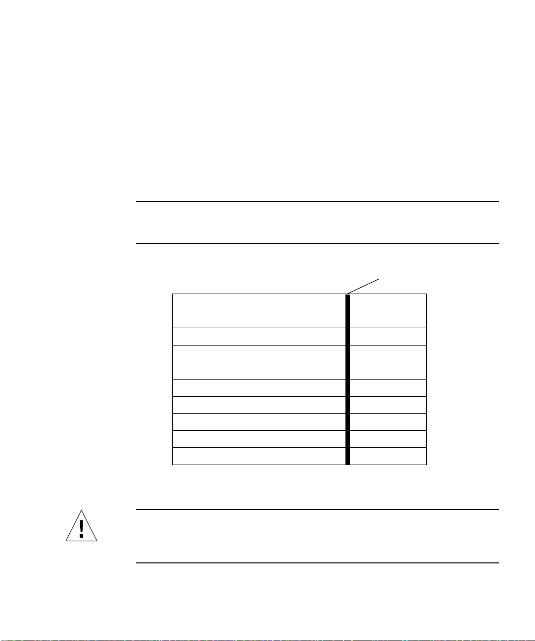
Typographic Conventions
TABLEP-1 Typographic Conventions
Typeface Meaning Examples
AaBbCc123 The names of commands, files,
and directories; on-screen
computer output
AaBbCc123
AaBbCc123 Book titles, new words or terms,
What you type, when
contrasted with on-screen
computer output
words to be emphasized
Edit your .login file.
Use ls -a to list all files.
% You have mail.
% su
Password:
Read Chapter 6 in the User’s Guide.
These are called class options.
You must be superuser to do this.
Command-line variable; replace
with a real name or value
xvi Sun Quad FastEthernet 6U CompactPCI Adapter Installation and User’s Guide • June 2000
To delete a file, type rm filename.
Page 17

Shell Prompts
TABLEP-2 Shell Prompts
Shell Prompt
C shell machine_name%
C shell superuser machine_name#
Bourne shell and Korn shell $
Bourne shell and Korn shell superuser #
Related Documentation
TABLEP-3 Related Documentation
Application Title or Description
Adapter installation, removal, and
replacement
Device driver configuration Platform Notes: The Sun Quad FastEthernet Device
Managing networks Solaris System Administration Guide,
SunVTS™ diagnostic testing SunVTS User’s Guide
OpenBoot™ PROM commands OpenBoot 3.x Command Reference Manual
Your system’s:
• Service Manual
• Installation Manual
• Administrator’s Guide
Driver
Volumes 1 through 3
SunVTS Test Reference Manual
Preface xvii
Page 18

Accessing Sun Documentation Online
The docs.sun.comsmweb site enables you to access Solaris technical
documentation on the Web. You can browse the docs.sun.com archive or search
for a specific book title or subject at:
http://docs.sun.com
Documentation and product information for the Netra™ product line are available
at:
http://www.sun.com/netra
Ordering Sun Documentation
Fatbrain.com, an Internet professional bookstore, stocks select product
documentation from Sun Microsystems, Inc.
For a list of documents and how to order them, visit the Sun Documentation Center
on Fatbrain.com at:
http://www.fatbrain.com/documentation/sun
Sun Welcomes Your Comments
We are interested in improving our documentation and welcome your comments
and suggestions. You can email your comments to us at:
docfeedback@sun.com
Please include the part number (806-2991-10) of your document in the subject line of
your email.
xviii Sun Quad FastEthernet 6U CompactPCI Adapter Installation and User’s Guide • June 2000
Page 19

CHAPTER
1
Overview of the
Sun Quad FastEthernet 6U
CompactPCI Adapter
This chapter contains an overview of the Sun Quad FastEthernet 6U CompactPCI
adapter, including:
■ “Product Description” on page 2
■ “Features” on page 3
■ “Overview of the Installation Procedure” on page 4
1
Page 20
Product Description
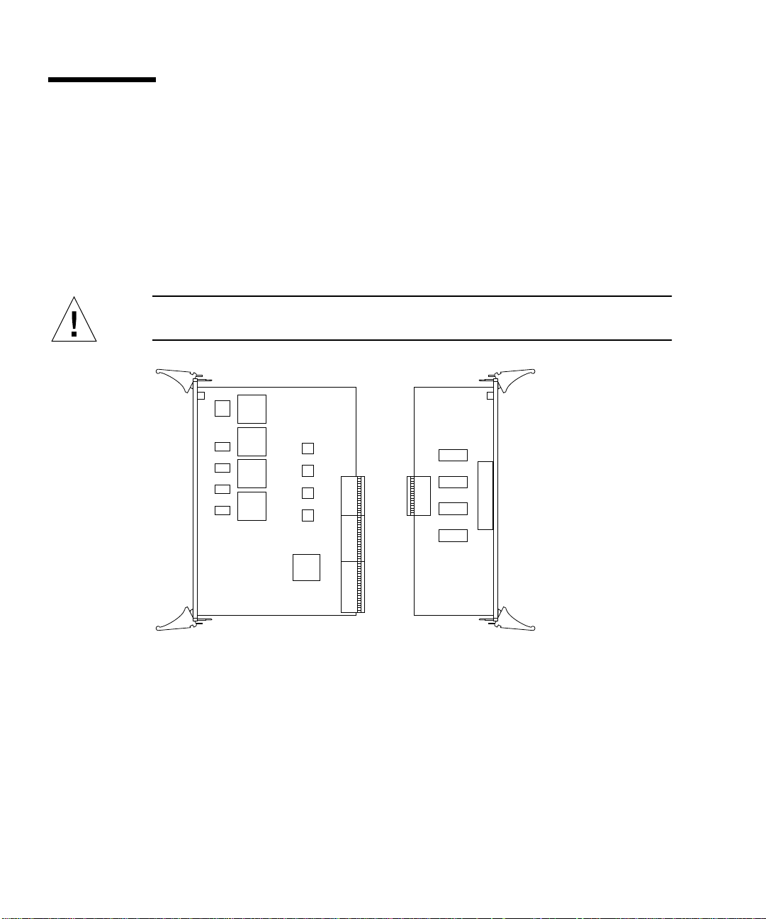
The Sun Quad FastEthernet 6U CompactPCI adapter contains four fully buffered
twisted-pair Ethernet ports (RJ-45), providing four switchable 10BASE-T/
100BASE-TX channels, on a CompactPCI adapter.
The adapter is available for front- and rear-access CompactPCI systems. For
rear-access systems, the adapter consists of two cards: the front card and the rear
transition card (see
front card (see
Caution – The front-access version the adapter is designed for front-access systems
only. Do not attempt to install this adapter into a rear access system.
FIGURE 1-1). For front-access systems, the adapter consists of one
FIGURE 1-2).
Rear transition cardFront card
FIGURE 1-1 Sun Quad FastEthernet 6U CompactPCI Adapter (Rear-Access Version)
2 Sun Quad FastEthernet 6U CompactPCI Adapter Installation and User’s Guide • June 2000
Page 21
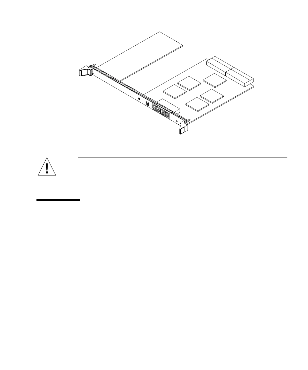
FIGURE 1-2 Sun Quad FastEthernet 6U CompactPCI Adapter (Front-Access Version)
Caution – Do not attempt to use the rear-access adapter’s rear transition card
(
FIGURE 1-1) with the front-access adapter (FIGURE 1-2). Using this combination is not
supported and may damage the cards and the system. The front-access adapter is for
front-access systems only, and the rear-access adapter is for rear-access systems only.
Features
This adapter offers the following features:
■ Fully compliant with the ANSI/IEEE standard 802.3 CSMA/CD physical-layer
specification.
■ Four Switchable 10BASE-T/100BASE-TX Ethernet channels with
autonegotiation. Conforms to IEEE 802.3u Ethernet standard.
■ Provides operation of up to 100 meters of twisted-pair without use of
repeaters.
■ Four independent Ethernet channels that run at either 10 Mbps or 100 Mbps.
■ Half-duplex or full-duplex operation modes.
■ Multiple 48-bit IEEE 802.3 style medium access control (MAC) identifiers, one for
each channel.
■ Link integrity LED for each channel.
■ Hot-swappable using the Intel 21554 chip.
Chapter 1 Overview of the Sun Quad FastEthernet 6U CompactPCI Adapter 3
Page 22

Overview of the Installation Procedure
This section presents an overview of the terminology and lists the major tasks you
will perform when installing the adapter into your system. Because of the
complexity of the networking environment, your specific installation procedure may
require tasks not listed below.
Installation Methods
The adapter is a hot-swappable component that can be installed in a hot-swapcompliant server without interrupting the operation of the system. The adapter can
also be installed in cold-swap mode, where you power off the system before you
install the adapter.
Before beginning the installation, you should determine whether you want to
perform a hot-swap or a cold-swap installation of the adapter.
■ In a hot-swap installation, you can install the adapter while the system is running,
without interrupting the operation of the server. Depending on the level of hot
swap your server is running (full or basic), you may be required to enter software
commands during the installation.
■ In a cold-swap installation, you must shut down the operating system and power
off the server before installing the adapter. After the installation, you must power
the system back on in order for the server to recognize the new adapter. You may
be required to use system-specific software commands to power off and power on
your system.
Note – This manual describes the general procedure needed for either a hot-swap or
a cold-swap installation. Because software commands and LED displays can differ
for each server, refer to your server’s documentation for the exact installation
procedures. For example, if you are installing the adapter in a Sun™ Netra™ ct
server, refer to the Netra ct Server Service Manual.
Models of Hot Swap
Hot swap, a key feature of the PCI Industrial Computer Manufacturers Group
(PICMG) standard, means that a CompactPCI adapter that meets the PICMG
standard can be reliably inserted into or extracted from a powered and operating
4 Sun Quad FastEthernet 6U CompactPCI Adapter Installation and User’s Guide • June 2000
Page 23

CompactPCI platform without affecting the other functions of the platform. The
standard also defines state transitions for the hardware and software connection
processes that allow the card to be connected and configured.
The adapter supports two models of hot swap:
■ Basic hot swap
■ Full hot swap
The models can be explained by first defining these two processes:
■ Hardware connection process—the electrical connection (and disconnection) of an
I/O card.
■ Software connection process—the software management by the operating system
of the board (allocating and releasing resources, attaching and detaching device
drivers, and so on).
In the basic hot-swap model, the hardware connection process can be performed
automatically by the hardware, while the software connection process requires
operator assistance.
In the full hot-swap model, both the hardware and the software connection process
are performed automatically.
If you install the adapter in a server set to full hot-swap mode, you will not need to
type in any software commands during the installation. However, if you install the
adapter in a server set to basic hot-swap mode, you will need to type in software
commands during the installation. For example, if you were installing the adapter in
a Netra ct server set to basic hot-swap mode, you would use the cfgadm command
to identify and attach the adapter during the installation.
Installing the Rear-Access Adapter
The following table lists the main procedures you will perform when you install and
configure the rear-access adapter (
TABLE1-1 Rear-Access Installation Overview
Task Chapter or Section Documented
Installing the adapter into the system Chapter 2
Connecting the Ethernet cables “Connecting the Cables to the Rear Transition Card”
Configuring the network interfaces “Attaching the Sun Quad FastEthernet Interfaces to
Chapter 1 Overview of the Sun Quad FastEthernet 6U CompactPCI Adapter 5
FIGURE 1-1).
on page 26
the Network” on page 42
Page 24

Installing the Front-Access Adapter
The following table lists the main procedures you will perform when you install and
configure the front-access adapter (
TABLE1-2 Front-Access Installation Overview
Task Chapter or Section Documented
Installing the adapter into the system Chapter 3
Connecting the Ethernet cables “Connecting the Cables to the Front-Access
Configuring the network interfaces “Attaching the Sun Quad FastEthernet Interfaces to
FIGURE 1-2).
Adapter” on page 40
the Network” on page 42
6 Sun Quad FastEthernet 6U CompactPCI Adapter Installation and User’s Guide • June 2000
Page 25
CHAPTER
2
Installing the Rear-Access Adapter
This chapter describes how to install the rear-access version of the Sun Quad
FastEthernet 6U CompactPCI adapter in a hot-swap-compatible server.
The rear-access version of the adapter is composed of two separate cards: a front
card, which contains the hot-swap LED, and a rear transition card, which contains
the cable connections and link LEDs. This chapter includes instructions for installing
the adapter’s two cards in both hot-swap mode (with the system powered on) and
cold-swap mode (with the system powered off).
To install the adapter, you must first install the rear transition card in a rear
CompactPCI slot of the server, and then you can install the front card in the
associated front slot of the server. After installing the cards, connect the cables to the
connectors on the rear transition card.
Caution – Wherever possible, this chapter provides explicit instructions for
installing the adapter in your system. However, you must refer to your system’s
documentation for the specific I/O card installation instructions. Your system’s
service manual will describe the system-specific software commands and the usage
of system LEDs required for installation.
This chapter contains the following sections:
■ “Preparing for the Installation” on page 8
■ “Installing the Rear-Access Adapter in Hot-Swap Mode” on page 10
■ “Installing the Rear-Access Adapter in Cold-Swap Mode” on page 21
■ “Connecting the Cables to the Rear Transition Card” on page 26
Note – After installing the adapter in the system, see Chapter 4 for the software
configuration instructions.
7
Page 26

Preparing for the Installation
Before installing the adapter, prepare for the installation by assembling the
appropriate tools, unpacking the ship kit, selecting a CompactPCI slot, and
determining a mode of installation.
Tools and Equipment Needed
You will need:
■ A No. 0 Phillips screwdriver
■ An antistatic wrist strap (included in the ship kit)
■ Ethernet cables to connect the adapter to an Ethernet network
■ Electrostatic discharge (ESD) mat (optional)
Contents of the Ship Kit
The ship kit contains the following items:
■ Front card
■ Rear transition card
■ Antistatic wrist strap
■ This manual
■ A product note document
Caution – Electrostatic discharge can damage the integrated circuits on the cards.
Leave the cards in their antistatic envelopes until you are ready to install them in the
system.
8 Sun Quad FastEthernet 6U CompactPCI Adapter Installation and User’s Guide • June 2000
Page 27
Selecting a CompactPCI Slot Pair in the System
The rear-access version of the adapter is exclusively designed to be installed in a
rear-accessible 6U system. You must first install the rear transition card in a rear
CompactPCI slot of the server, and then you can install the front card in the
associated front slot of the server. Before starting to install the adapter, select an
available CompactPCI slot pair in the server.
For example, in a Sun Netra ct 800 server (see
FIGURE 2-1), there are seven 6U
CompactPCI I/O slot pairs available (slot 1 of this server will always be occupied by
a CPU card). Install the adapter’s front card and rear transition card (RTC) into an
open slot pair. (Slot 8, in some configurations, may be occupied by an alarm card.)
Note – Refer to your system’s service manual for the exact locations of the
CompactPCI I/O slots in the system, and to determine the most appropriate slot in
which to install the adapter.
Midplane
Front of
chassis
Slot 2
Slot 3
Slot 4
Slot 5
Slot 6
Hard disk drives
CPU card
6U CompactPCI I/O card
6U CompactPCI I/O card
6U CompactPCI I/O card
6U CompactPCI I/O card
6U CompactPCI I/O card
CPU RTCSlot 1
I/O rear card
I/O rear card
I/O rear card
I/O rear card
I/O rear card
Rear of
chassis
Slot 1
Slot 2
Slot 3
Slot 4
Slot 5
Slot 6
Slot 7
Slot 8
FIGURE 2-1 CompactPCI Slot Pairs in a Sun Netra ct 800 Server (Top View)
6U CompactPCI I/O card
Alarm card
I/O rear card
Alarm RTC
Slot 7
Slot 8
Caution – The rear transition card and the front card must be installed in associated
CompactPCI slots. For example, if you install the rear transition card in the server’s
rear I/O slot 3, you must install the front card in the server’s front I/O slot 3. You
can panic the server if you install the cards in nonassociated slots.
Chapter 2 Installing the Rear-Access Adapter 9
Page 28
Determining the Installation Type
You can install the adapter in the system in either a hot-swap mode or in a coldswap mode. (See “Installation Methods” on page 4 for more information.)
■ Hot swap—see “Installing the Rear-Access Adapter in Hot-Swap Mode” on
page 10 for the procedure.
■ Cold swap—see “Installing the Rear-Access Adapter in Cold-Swap Mode” on
page 21 for the procedure.
After installing the adapter, see “Connecting the Cables to the Rear Transition Card”
on page 26 for instructions on connecting the cables.
Installing the Rear-Access Adapter in Hot-Swap Mode
When installing the adapter in a server in hot-swap mode, you must consult the
documentation that shipped with the server. The server’s documentation will
describe the specific software commands and hardware components such as LEDs
that are used when installing the adapter.
This section contains two procedures:
■ “To Install the Rear Transition Card” on page 11
■ “To Install the Rear-Access Front Card” on page 16
After installing the adapter, see “Connecting the Cables to the Rear Transition Card”
on page 26 for instructions on connecting the Ethernet cables.
Caution – Always install the adapter’s rear transition card before installing the front
card. In a hot-swap environment, you can panic the system if you install the front
card first.
Caution – Do not use excessive force when installing the adapter’s front or rear
transition card into the CompactPCI slot. You may damage the card’s connector or
the pins on the midplane, causing permanent damage to the card or to the system. If
a card does not seat properly when you apply even pressure, remove the card and
carefully reinstall it.
10 Sun Quad FastEthernet 6U CompactPCI Adapter Installation and User’s Guide • June 2000
Page 29
▼ To Install the Rear Transition Card
Install the rear transition card in the rear CompactPCI slot that you selected in
“Selecting a CompactPCI Slot Pair in the System” on page 9.
1. Retrieve the wrist strap from the adapter’s ship kit.
2. Attach the adhesive copper strip of the antistatic wrist strap to the metal chassis of
the system. Wrap the other end twice around your wrist, with the adhesive side
against your skin.
3. If the rear slot contains a factory-installed filler panel, remove the filler panel
before installing the rear transition card.
Refer to the system’s documentation for instructions on how to remove the filler
panel. Typically, you will need to loosen the filler panel’s captive screws before
removing the panel from the system.
4. Remove the rear transition card from its antistatic envelope and place it on an
ESD mat (if available) near the system.
If an ESD mat is not available, you can place the card on the antistatic envelope it
was packaged in.
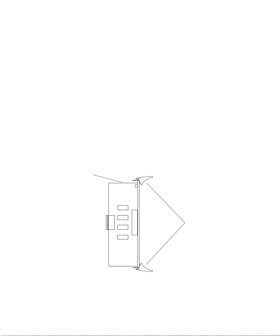
Before installing the card in the system, you will need to open the card’s ejection
levers (see
Top of
the card
FIGURE 2-2).
Ejection levers
FIGURE 2-2 Location of the Rear Transition Card’s Ejection Levers
Chapter 2 Installing the Rear-Access Adapter 11
Page 30
5. With the card resting on the mat, press the levers outward to open the ejection levers.
The card may contain different types of ejection levers. For example,
FIGURE 2-3
shows two possible types of levers. The levers may also contain a locking
mechanism that must be unlocked before you can open the levers.
Locking mechanism
Locking mechanism
FIGURE 2-3 Opening the Ejection Levers (Two Types of Levers)
6. Lift up the card, and keeping it perfectly vertical, carefully slide the card in the
selected rear slot.
Be sure to align the top and bottom of the card in the slot’s card guides (
Also, make sure the ejection levers remain open while you slide the card into the
slot.
12 Sun Quad FastEthernet 6U CompactPCI Adapter Installation and User’s Guide • June 2000
FIGURE 2-4).
Page 31

FIGURE 2-4 Aligning the Rear Transition Card With the CompactPCI Slot Card Guide
7. Push the card all the way in the slot until the two ejection levers move inward.
The tabs of the ejection levers (see
FIGURE 2-5) should fit smoothly into the
rectangular cutouts in the top and bottom of the slot.
Tabs Tabs
FIGURE 2-5 Location of the Ejection Lever Tabs (Two Types of Levers)
Chapter 2 Installing the Rear-Access Adapter 13
Page 32

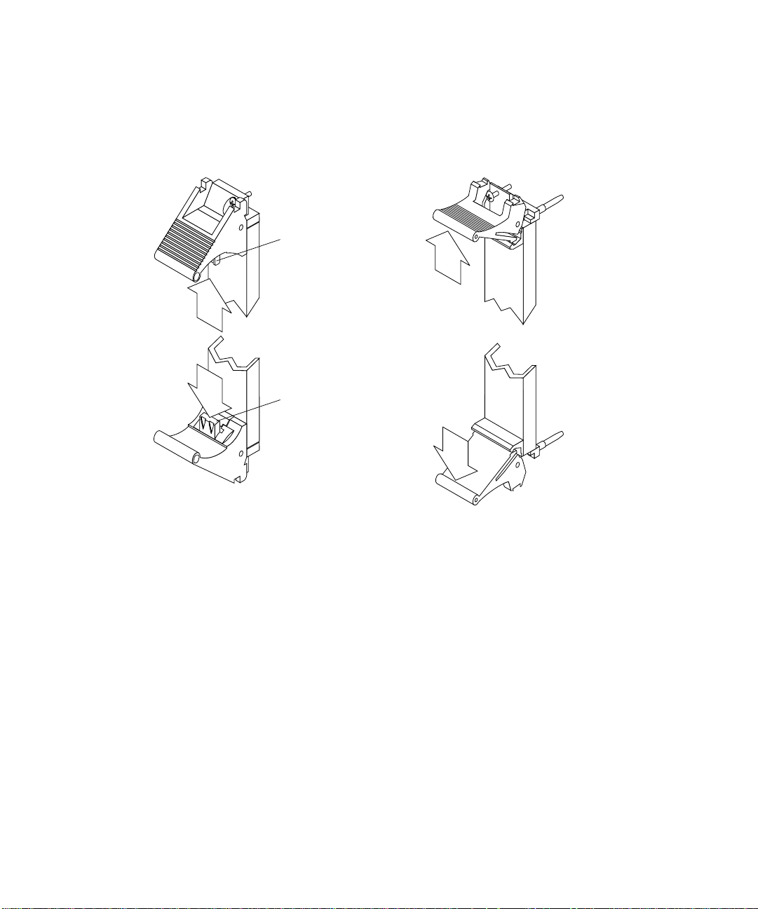
8. Close the ejection levers by pushing the levers in toward the card.
The card may contain different types of ejection levers. For example,
shows two possible types of levers. The levers may also contain a locking
mechanism that will lock when the levers have been properly closed.
FIGURE 2-6
FIGURE 2-6 Closing the Ejection Levers (Two Types of Levers)
When installed correctly, the ejection lever tabs will fit smoothly into the rectangular
cutouts in the top and bottom of the slot (
14 Sun Quad FastEthernet 6U CompactPCI Adapter Installation and User’s Guide • June 2000
FIGURE 2-7).
Page 33

Cutouts
Tabs
Tabs
FIGURE 2-7 Ejection Levers Installed in the Slot’s Cutouts (Two Types of Levers)
9. Using a No. 0 Phillips screwdriver, tighten the captive screws inside the card’s top
and bottom ejection levers.
The card may contain different types of ejection levers. For example,
FIGURE 2-8
shows two possible types of levers.
FIGURE 2-8 Tightening the Ejection Lever Captive Screws (Two Types of Levers)
Chapter 2 Installing the Rear-Access Adapter 15
Page 34

▼ To Install the Rear-Access Front Card
After installing the rear transition card, you can install the front card. The front card
is hot-swap aware, which means the system will recognize the card during the
installation.
1. Walk to the front of the server.
2. Confirm or reattach your wrist strap to the system’s chassis and to your wrist.
If necessary, remove the strap from the rear of the chassis and attach it to the front of
the chassis.
3. Locate the slot where you plan to install the front card.
Caution – This card must be installed in the front CompactPCI slot that is directly
associated with the rear slot where you installed the rear transition card. If you
install the card in a different slot, the system may panic.
For example, if you installed the rear transition card into the rear slot 3, you must
install the front card into the front slot 3. See “Selecting a CompactPCI Slot Pair in
the System” on page 9 for more information.
4. If the front slot contains a factory-installed filler panel, remove the filler panel
before installing the card.
Refer to the system’s documentation for instructions on how to remove the filler
panel. Typically, you will need to loosen the filler panel’s captive screws before
removing the panel from the system.
5. Remove the card from its antistatic envelope and place it on an ESD mat (if
available) near the system.
If an ESD mat is not available, you can place the card on the antistatic envelope it
was packaged in.
16 Sun Quad FastEthernet 6U CompactPCI Adapter Installation and User’s Guide • June 2000
Page 35

Before installing the card in the system, you will need to open the card’s ejection
levers (see
FIGURE 2-9).
Top of the card
Ejection levers
FIGURE 2-9 Location of the Front Card’s Ejection Levers
6. With the card resting on the on the mat, press the levers outward to open the ejection levers.
The card may contain different types of ejection levers. For example,
FIGURE 2-3
shows two possible types of levers. The levers may also contain a locking
mechanism that must be unlocked before you can open the levers. The ejection
levers may be different than the ones on the rear transition card.
Chapter 2 Installing the Rear-Access Adapter 17
Page 36

7. Lift up the card, and keeping it perfectly vertical, carefully slide the card into the
selected slot.
Be sure to align the top and bottom of the card into the slot’s card guides
(
FIGURE 2-10). Also, make sure the ejection levers remain open while you slide the
card into the slot.
FIGURE 2-10 Aligning the Front Card With the CompactPCI Slot Card Guide
8. Push the card all the way into the slot until the two ejection levers move inward.
The tabs of the ejection levers (see
FIGURE 2-5) should fit smoothly into the
rectangular cutouts in the top and bottom of the slot.
9. Close the ejection levers by pushing the levers in toward the card.
The card may contain different types of ejection levers. For example,
shows two possible types of levers. The levers may also contain a locking
mechanism that will lock when the levers have been properly closed. When installed
correctly, the ejection lever tabs will fit smoothly into the rectangular cutouts of the
slot (
FIGURE 2-7).
18 Sun Quad FastEthernet 6U CompactPCI Adapter Installation and User’s Guide • June 2000
FIGURE 2-6
Page 37

10. Locate the hot-swap LED on the front card to determine if the card has been
activated and is attached to the system (see
Compact PCI
FIGURE 2-11).
Hot-swap LED
Hot
Swap
FIGURE 2-11 Location of the Rear-Access Adapter’s Hot-Swap LED on the Front Card
The hot-swap LED shows whether the adapter has been activated.
■ If the hot-swap LED is OFF (unlit), the I/O slots in the server have been set to full
hot swap and the adapter has been activated. Go to Step 15.
■ If the hot-swap LED is ON, then the I/O slots in the server have been set to basic
hot swap. You must use software commands to activate the I/O card. Go to
Step 11.
Note – You should also use the hot-swap LEDs on the server when installing the
adapter. For example, Netra ct servers contain an OK to Remove LED ( ) on the
system status panel that is used like the hot-swap LED on this adapter. Refer to your
system’s service manual for a description on how the hot-swap LEDs are used
during a hot-swap installation.
11. Remove the wrist strap from the chassis and from your wrist.
Chapter 2 Installing the Rear-Access Adapter 19
Page 38

12. Log in to the server.
Refer to the server’s documentation for the procedure.
13. At the terminal prompt, type the hot-swap software commands to identify and
attach the adapter to the server.
These commands may be specific to the server. Refer to the server’s documentation
for the correct commands and procedures.
For example, if you are installing the adapter into a Netra ct server, you would use
the cfgadm pci command to list the attachment point IDs in the server. On a
Netra ct 800 server, you should see feedback similar to the following:
# cfgadm pci
Ap_Id Type Receptacle Occupant Condition
pci_pci0:cpci_slot2 unknown empty unconfigured unknown
pci_pci0:cpci_slot3 stpcipci/fhs connected configured ok
pci_pci0:cpci_slot4 stpcipci/fhs connected configured ok
pci_pci0:cpci_slot5 unknown empty unconfigured unknown
pci_pci0:cpci_slot6 unknown empty unconfigured unknown
pci_pci0:cpci_slot7 unknown empty unconfigured unknown
pci_pci0:cpci_slot8 stpcipci/fhs connected configured ok
Once you have identified the attachment point ID on the Netra ct server, you can use
the following commands to attach the adapter to the server:
# cfgadm -c connect attachment-point-id
# cfgadm -c configure attachment-point-id
For example, if the attachment point ID is
pci_pci0:cpci_slot3 (the third
CompactPCI slot on the server), you would type:
# cfgadm -c connect pci_pci0:cpci_slot3
# cfgadm -c configure pci_pci0:cpci_slot3
The hot-swap LED should go off, indicating that the card has been activated. The
LEDs on the system should also show that the card has been successfully connected.
14. Reattach the wrist strap to the chassis and your wrist.
15. Using a No. 0 Phillips screwdriver, tighten the captive screws inside the card’s top
and bottom ejection levers.
The card may contain different types of ejection levers. For example,
shows two possible types of levers.
20 Sun Quad FastEthernet 6U CompactPCI Adapter Installation and User’s Guide • June 2000
FIGURE 2-8
Page 39

16. Remove the wrist strap from the chassis and from your wrist.
See “Connecting the Cables to the Rear Transition Card” on page 26 for instructions
on connecting the cables to the rear transition card.
Installing the Rear-Access Adapter in Cold-Swap Mode
Note – When installing the adapter in a server in cold-swap mode, you must consult
the documentation that shipped with the server. The server’s documentation will
describe the specific software commands required to power off and power on the
server.
Installing the rear-access adapter in cold-swap mode involves the following
procedures:
■ “To Power Off the Server” on page 21
■ “To Install the Rear Transition Card” on page 22
■ “To Install the Rear-Access Front Card” on page 23
■ “To Power On the Server” on page 25
After installing the adapter, see “Connecting the Cables to the Rear Transition Card”
on page 26 for instructions on connecting the cables to the rear card.
Caution – Do not use excessive force when installing the adapter’s front or rear
transition card into the CompactPCI slot. You may damage the card’s connector or
the pins on the midplane, causing permanent damage to the card or to the system. If
a card does not seat properly when you apply even pressure, remove the card and
carefully reinstall it.
▼ To Power Off the Server
This procedure describes a general overview of powering off the server. Refer to
your system’s documentation for the exact procedure.
1. Before shutting down the operating environment and halting the system, ensure
that all significant application activity on the server has stopped.
Chapter 2 Installing the Rear-Access Adapter 21
Page 40

2. Follow the appropriate procedures, as documented in the system’s service manual,
to shut down and power off the server.
Refer to the system’s documentation for the complete power off procedure. For
example, if you installed the adapter in a Netra ct server, refer to the Netra ct Server
Service Manual. This manual contains the power on procedures.
3. Verify that the system’s power LED is off (unlit), indicating that the system has
completely powered off.
Refer to the system’s documentation for the location of the power LED. For example,
on a Netra ct server, the power LED is on the front panel.
Once the system has been shut down and powered off, you can safely install the rear
and front cards.
▼ To Install the Rear Transition Card
Install the rear transition card in the rear CompactPCI slot that you selected in
“Selecting a CompactPCI Slot Pair in the System” on page 9.
1. Retrieve the wrist strap from the adapter’s ship kit.
2. Attach the adhesive copper strip of the antistatic wrist strap to the metal chassis of
the system. Wrap the other end twice around your wrist, with the adhesive side
against your skin.
3. If the rear slot contains a factory-installed filler panel, remove the filler panel
before installing the rear transition card.
Refer to the system’s documentation for instructions on how to remove the filler
panel. Typically, you will need to loosen the filler panel’s captive screws before
removing the panel from the system.
4. Remove the rear transition card from its antistatic envelope and place it on an
ESD mat (if available) near the system.
If an ESD mat is not available, you can place the card on the antistatic envelope it
was packaged in.
Before installing the card in the system, you will need to open the card’s ejection
levers (see
FIGURE 2-2).
5. With the card resting on the mat, press the levers outward to open the ejection levers.
The card may contain different types of ejection levers. For example,
shows two possible types of levers. The levers may also contain a locking
mechanism that must be unlocked before you can open the levers.
22 Sun Quad FastEthernet 6U CompactPCI Adapter Installation and User’s Guide • June 2000
FIGURE 2-3
Page 41

6. Lift up the card, and keeping it perfectly vertical, carefully slide the card into the
selected rear slot.
Be sure to align the top and bottom of the card into the slot’s card guides
(
FIGURE 2-4). Also, make sure the ejection levers remain open while you slide the
card into the slot.
7. Push the card all the way into the slot until the two ejection levers move inward.
The tabs of the ejection levers (see
FIGURE 2-5) should fit smoothly into the
rectangular cutouts in the top and bottom of the slot.
8. Close the ejection levers by pushing the levers in toward the card.
The card may contain different types of ejection levers. For example,
FIGURE 2-6
shows two possible types of levers. The levers may also contain a locking
mechanism that will lock when the levers have been properly closed. When installed
correctly, the ejection lever tabs will fit smoothly into the rectangular cutouts in the
top and bottom of the slot (
FIGURE 2-7).
9. Using a No. 0 Phillips screwdriver, tighten the captive screws inside the card’s top
and bottom ejection levers.
The card may contain different types of ejection levers. For example,
FIGURE 2-8
shows two possible types of levers.
▼ To Install the Rear-Access Front Card
After installing the rear transition card, you can install the front card.
1. Walk to the front of the server.
2. Confirm or reattach your wrist strap to the system’s chassis and to your wrist.
If necessary, remove the strap from the rear of the chassis and attach it to the front of
the chassis.
3. Locate the slot where you plan to install the front card.
Caution – This card must be installed in the front CompactPCI slot that is directly
associated with the rear slot where you installed the rear transition card. If you
install the card in a different slot, the system may panic.
For example, if you installed the rear transition card into the rear slot 3, you must
install the front card into the front slot 3. See “Selecting a CompactPCI Slot Pair in
the System” on page 9 for more information.
Chapter 2 Installing the Rear-Access Adapter 23
Page 42

4. If the front slot contains a factory-installed filler panel, remove the filler panel
before installing the card.
Refer to the system’s documentation for instructions on how to remove the filler
panel. Typically, you will need to loosen the filler panel’s captive screws before
removing the panel from the system.
5. Remove the card from its antistatic envelope and place it on an ESD mat (if
available) near the system.
If an ESD mat is not available, you can place the card on the antistatic envelope it
was packaged in.
Before installing the card in the system, you will need to open the card’s ejection
levers (see
FIGURE 2-9).
6. With the card resting on the on the mat, press the levers outward to open the ejection levers.
The card may contain different types of ejection levers. For example,
FIGURE 2-3
shows two possible types of levers. The levers may also contain a locking
mechanism that must be unlocked before you can open the levers. The ejection
levers may be different than the ones on the rear transition card.
7. Lift up the card, and keeping it perfectly vertical, carefully slide the card into the
selected slot.
Be sure to align the top and bottom of the card into the slot’s card guides
(
FIGURE 2-10). Also, make sure the ejection levers remain open while you slide the
card into the slot.
8. Push the card all the way into the slot until the two ejection levers move inward.
The tabs of the ejection levers (see
FIGURE 2-5) should fit smoothly into the
rectangular cutouts in the top and bottom of the slot.
9. Close the ejection levers by pushing the levers in toward the card.
The card may contain different types of ejection levers. For example,
shows two possible types of levers. The levers may also contain a locking
mechanism that will lock when the levers have been properly closed. When installed
correctly, the ejection lever tabs will fit smoothly into the rectangular cutouts of the
slot (
FIGURE 2-7).
10. Using a No. 0 Phillips screwdriver, tighten the captive screws inside the card’s top
and bottom ejection levers.
The card may contain different types of ejection levers. For example,
shows two possible types of levers.
11. Remove the wrist strap from the chassis and from your wrist.
After installing the adapter, see “Connecting the Cables to the Rear Transition Card”
on page 26 for instructions on connecting the cables to the rear card.
24 Sun Quad FastEthernet 6U CompactPCI Adapter Installation and User’s Guide • June 2000
FIGURE 2-6
FIGURE 2-8
Page 43

▼ To Power On the Server
This procedure describes a general overview for powering on the server. Refer to
your server’s documentation for the exact procedure.
1. Before powering on the server, make sure that all any peripheral devices
connected to the server are powered on.
2. Follow the appropriate procedures, as documented in the server’s service manual,
to power on the system.
Refer to the server’s documentation for the complete power on procedure.
For example, if you installed the adapter in a Netra ct server, refer to the Netra ct
Server Service Manual. This manual contains the power on procedures.
3. During the power on sequence, watch the hot-swap LED on the adapter’s front
card (
FIGURE 2-11).
■ The LED should blink quickly and then stay off if the adapter was installed
correctly.
■ If the hot-swap LED remains on (lit), the adapter was not installed correctly. One
or both of the cards may not be seated correctly in the slot. You must remove and
reinstall the adapter’s two cards to make sure that they sit correctly in the slots.
Use the cold-swap procedures to re-install the two cards:
■ Power off the server
■ Remove and replace the rear transition card
■ Remove and replace the front card
■ Power on the server
Refer to the system’s documentation for additional troubleshooting instructions.
4. Verify that the server’s power LED is on (lit), indicating that the system has
completely powered on.
Refer to the server’s documentation for the location of the power LED. For example,
on a Netra ct server, the power LED is on the front panel.
Chapter 2 Installing the Rear-Access Adapter 25
Page 44
Connecting the Cables to the Rear Transition Card
After installing the adapter in the system, you can attach the Ethernet cables to the
Ethernet ports on the rear transition card.
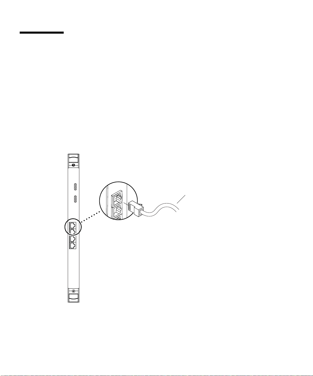
▼ To Connect the Cables to the Rear Ethernet Ports
1. Locate the adapter’s rear transition card that you installed in the system.
2. Connect one end of an Ethernet cable to an Ethernet port on the rear transition
card (see
FIGURE 2-12).
Ethernet cable
FIGURE 2-12 Connecting Cables to the Rear Transition Card
3. Connect the other end of the Ethernet cable to an active Ethernet network.
Repeat Steps 2 and 3 for each Ethernet cable you need to connect.
26 Sun Quad FastEthernet 6U CompactPCI Adapter Installation and User’s Guide • June 2000
Page 45

CHAPTER
3
Installing the Front-Access Adapter
This chapter describes how to install the front-access version of the Sun Quad
FastEthernet 6U CompactPCI adapter in a CompactPCI hot-swap-compatible server.
The front-access version of the Sun Quad FastEthernet 6U CompactPCI adapter
contains a hot-swap LED, four Ethernet ports, and link LEDs. This chapter includes
instructions for installing the adapter in both hot-swap mode (with the system
powered on) and cold-swap mode (with the system powered off).
Caution – Wherever possible, this chapter provides explicit instructions for
installing the adapter in your system. However, you must refer to your system’s
documentation for the specific I/O card installation instructions. Your system’s
service manual will describe the system-specific software commands and the usage
of system LEDs required for installation.
This chapter contains the following sections:
■ “Preparing for the Installation” on page 28
■ “Installing the Front-Access Adapter in Hot-Swap Mode” on page 29
■ “Installing the Front-Access Adapter in Cold-Swap Mode” on page 36
■ “Connecting the Cables to the Front-Access Adapter” on page 40
Note – After installing the adapter in the system, see Chapter 4 for the software
configuration instructions.
Caution – The front-access version of the adapter is designed to be installed in
front-access systems only. Do not attempt to install this adapter in a rear-access
system.
27
Page 46

Preparing for the Installation
Before installing the adapter, prepare for the installation by assembling the
appropriate tools, unpacking the ship kit, selecting a CompactPCI slot, and
determining a mode of installation.
Tools and Equipment Needed
You will need:
■ A No. 0 Phillips screwdriver
■ An antistatic wrist strap (included in the ship kit)
■ Ethernet cables to connect the adapter to an Ethernet network
■ Electrostatic discharge (ESD) mat (optional)
Contents of the Ship Kit
The ship kit contains the following items:
■ Front-access adapter
■ Antistatic wrist strap
■ This manual
■ A product note document
Caution – Electrostatic discharge can damage the integrated circuits on the adapter.
Leave the adapter in its antistatic envelope until you are ready to install it in the
system.
Selecting a CompactPCI Slot in the System
The front-access version of the adapter is exclusively designed to be installed in a
front-access system with 6U CompactPCI slots. Before installing the adapter, select a
CompactPCI slot in the server where you want to install the adapter.
Note – Refer to your system’s service manual for the exact locations of the
CompactPCI I/O slots in the system, and to determine the most appropriate slot to
install the adapter.
28 Sun Quad FastEthernet 6U CompactPCI Adapter Installation and User’s Guide • June 2000
Page 47

Determining the Installation Type
You can install the adapter in the system in either a hot-swap mode or in a coldswap mode. (See “Installation Methods” on page 4 for more information.)
■ Hot swap—see “Installing the Front-Access Adapter in Hot-Swap Mode” on
page 29 for the procedure.
■ Cold swap—see “Installing the Front-Access Adapter in Cold-Swap Mode” on
page 36 for the procedure.
After installing the adapter, see “Connecting the Cables to the Front-Access
Adapter” on page 40 for instructions on connecting the cables.
Installing the Front-Access Adapter in Hot-Swap Mode
When installing the adapter in a server in hot-swap mode, you must consult the
documentation that shipped with the server. The server’s documentation will
describe the hot-swap commands and system LEDs that will be used when installing
the adapter.
Caution – Do not use excessive force when installing the adapter into the
CompactPCI slot. You may damage the adapter’s connector or the pins on the
midplane, causing permanent damage to the adapter or to the system. If the adapter
does not seat properly when you apply even pressure, remove the adapter and
carefully reinstall it.
▼ To Install the Front-Access Adapter in Hot-Swap
Mode
The adapter is hot-swap aware, which means the system will recognize the adapter
during the installation.
1. Retrieve the wrist strap from the adapter’s ship kit.
2. Attach the adhesive copper strip of the antistatic wrist strap to the metal chassis of
the system. Wrap the other end twice around your wrist, with the adhesive side
against your skin.
3. Locate the slot where you will install the adapter.
Chapter 3 Installing the Front-Access Adapter 29
Page 48

4. If the slot contains a factory-installed filler panel, remove the filler panel before
installing the adapter.
Refer to the system’s documentation for instructions on how to remove the filler
panel. Typically, you will need to loosen the filler panel’s captive screws before
removing the panel from the system.
5. Remove the adapter from its antistatic envelope and place it on an ESD mat (if
available) near the system.
If an ESD mat is not available, you can place the adapter on the antistatic envelope it
was packaged in.
Before installing the adapter in the system, you will need to open the adapter’s
ejection levers (see
Top of
the adapter
Ejection levers
in the locked
position
FIGURE 3-1).
FIGURE 3-1 Location of the Front-Access Adapter’s Ejection Levers
6. With the adapter resting on the mat, press the levers outward to open the ejection levers.
The adapter may contain different types of ejection levers. For example,
shows two possible types of levers. The levers may also contain a locking
mechanism that must be unlocked before you can open the levers.
30 Sun Quad FastEthernet 6U CompactPCI Adapter Installation and User’s Guide • June 2000
FIGURE 3-2
Page 49

Locking mechanism
Locking mechanism
FIGURE 3-2 Opening the Ejection Levers (Two Types of Levers)
7. Lift up the adapter, and keeping it perfectly vertical, carefully slide the adapter
into the selected slot.
Be sure to align the top and bottom of the adapter into the slot’s card guides
(
FIGURE 3-3). Also, make sure the ejection levers remain open while you slide the
adapter into the slot.
FIGURE 3-3 Aligning the Front Adapter in CompactPCI Slot Card Guide
Chapter 3 Installing the Front-Access Adapter 31
Page 50

8. Push the adapter all the way into the slot until the two ejection levers move inward.
The tabs of the ejection levers (see
FIGURE 3-4) should fit smoothly into the
rectangular cutouts in the top and bottom of the slot.
Tabs Tabs
FIGURE 3-4 Location of the Ejection Lever Tabs (Two Types of Levers)
9. Close the ejection levers by pushing the levers in toward the adapter.
The adapter may contain different types of ejection levers. For example,
FIGURE 3-5
shows two possible types of levers. The levers may also contain a locking
mechanism that will lock when the levers have been properly closed.
FIGURE 3-5 Closing the Ejection Levers (Two Types of Levers)
32 Sun Quad FastEthernet 6U CompactPCI Adapter Installation and User’s Guide • June 2000
Page 51

When installed correctly, the ejection lever tabs will fit smoothly into the rectangular
cutouts in the top and bottom of the slot (
FIGURE 3-6).
Cutouts
Tabs
Tabs
FIGURE 3-6 Ejection Lever Tabs Installed in the Slot’s Cutouts (Two Types of Levers)
10. Locate the hot-swap LED on the adapter to determine if the adapter has been
activated and is attached to the system (see
FIGURE 3-7).
Hot-swap LED
FIGURE 3-7 Location of the Front-Access Adapter’s Hot-Swap LED
Chapter 3 Installing the Front-Access Adapter 33
Page 52

The hot-swap LED shows whether the adapter has been activated.
■ If the hot-swap LED is OFF (unlit), the I/O slots in the server have been set to full
hot swap and the adapter has been activated. Go to Step 15.
■ If the hot-swap LED is ON, then the I/O slots in the server have been set to basic
hot swap. You must use software commands to activate the I/O card. Go to
Step 11.
Note – You should also use the hot-swap LEDs on the server when installing the
adapter. For example, Netra ct servers contain an OK to Remove LED ( ) on the
system status panel that is used like the hot-swap LED on this adapter. Refer to your
system’s service manual for a description on how the hot-swap LEDs are used
during a hot-swap installation.
11. Remove the wrist strap from the chassis and from your wrist.
12. Log in to the server.
Refer to the server’s documentation for the procedure.
13. At the terminal prompt, type the hot-swap software commands to identify and
attach the adapter to the server.
These commands may be specific to the server’s hot-swap software. Refer to the
server ’s documentation for the correct commands and procedures.
For example, if you are installing the adapter into a Netra ct server, you would use
the cfgadm pci command to list the attachment point IDs in the server. On a
Netra ct 800 server, you should see feedback similar to the following:
# cfgadm pci
Ap_Id Type Receptacle Occupant Condition
pci_pci0:cpci_slot2 unknown empty unconfigured unknown
pci_pci0:cpci_slot3 stpcipci/fhs connected configured ok
pci_pci0:cpci_slot4 stpcipci/fhs connected configured ok
pci_pci0:cpci_slot5 unknown empty unconfigured unknown
pci_pci0:cpci_slot6 unknown empty unconfigured unknown
pci_pci0:cpci_slot7 unknown empty unconfigured unknown
pci_pci0:cpci_slot8 stpcipci/fhs connected configured ok
Once you have identified the attachment point ID on the Netra ct server, you can use
the following commands to attach the adapter to the server:
# cfgadm -c connect attachment-point-id
# cfgadm -c configure attachment-point-id
34 Sun Quad FastEthernet 6U CompactPCI Adapter Installation and User’s Guide • June 2000
Page 53

For example, if the attachment point ID is pci_pci0:cpci_slot3 (the third
CompactPCI slot on the server), you would type:
# cfgadm -c connect pci_pci0:cpci_slot3
# cfgadm -c configure pci_pci0:cpci_slot3
The hot-swap LED should go off, indicating that the adapter has been activated.
14. Reattach the wrist strap to the chassis and to your wrist.
15. Using a No. 0 Phillips screwdriver, tighten the captive screws inside the adapter’s
top and bottom ejection levers.
The adapter may contain different types of ejection levers. For example,
FIGURE 3-8
shows two possible types of levers.
FIGURE 3-8 Tightening the Ejection Lever Captive Screws (Two Types of Levers)
16. Remove the wrist strap from the chassis and from your wrist.
After installing the adapter, see “Connecting the Cables to the Front-Access
Adapter” on page 40 for instructions on connecting the cables to the front-access
adapter.
Chapter 3 Installing the Front-Access Adapter 35
Page 54

Installing the Front-Access Adapter in Cold-Swap Mode
Note – When installing the adapter in a server in cold-swap mode, you must consult
the documentation that shipped with the server. The server’s documentation
describes the specific software commands required to power off and power on the
server.
Installing the front-access adapter in cold-swap mode involves the following
procedures:
■ “To Power Off the Server” on page 36
■ “To Install the Front-Access Adapter in Cold-Swap Mode” on page 37
■ “To Power On the Server” on page 38
Caution – Do not use excessive force when installing the adapter into the
CompactPCI slot. You may damage the adapter’s connector or the pins on the
midplane, causing permanent damage to the adapter or to the system. If the adapter
does not seat properly when you apply even pressure, remove the adapter and
carefully reinstall it.
▼ To Power Off the Server
This procedure describes a general overview of powering off the server. Refer to
your system’s documentation for the exact procedure.
1. Before shutting down the operating environment and halting the system, ensure
that all significant application activity on the server has stopped.
2. Follow the appropriate procedures, as documented in the system’s service manual,
to shut down and halt the system.
Refer to the system’s documentation for the complete power off procedure.
For example, if you were installing the adapter in a Netra ct server, you would refer
to the Netra ct Server Service Manual. The service manual contains the hardware and
software powering off procedures.
36 Sun Quad FastEthernet 6U CompactPCI Adapter Installation and User’s Guide • June 2000
Page 55

3. Verify that the system’s power LED is off (unlit), indicating that the system is
completely powered off.
Refer to the system’s documentation for the location of the power LED. For example,
on a Netra ct server, the power LED is on the front panel.
Once the system has been shut down and powered off, you can safely install the
adapter.
▼ To Install the Front-Access Adapter in Cold-
Swap Mode
1. Retrieve the wrist strap from the adapter’s ship kit.
2. Attach the adhesive copper strip of the antistatic wrist strap to the metal chassis of
the system. Wrap the other end twice around your wrist, with the adhesive side
against your skin.
3. Locate the slot where you will install the adapter.
4. If the slot contains a factory installed filler panel, remove the filler panel before
installing the adapter.
Refer to the system’s documentation for instructions on how to remove the filler
panel. Typically, you will need to loosen the filler panel’s captive screws before
removing the panel from the system.
5. Remove the adapter from its antistatic envelope and place it on an ESD mat (if
available) near the system.
If an ESD mat is not available, you can place the adapter on the antistatic envelope it
was shipped in.
Before installing the adapter in the system, you will need to open the adapter’s
ejection levers (see
FIGURE 3-1).
6. With the adapter resting on the on the mat, press the levers outward to open the ejection levers.
The adapter may contain different types of ejection levers. For example,
shows two possible types of levers. The levers may also contain a locking
mechanism that must be unlocked before you can open the levers.
7. Lift up the adapter, and keeping it perfectly vertical, carefully slide the adapter
into the selected slot.
Be sure to align the top and bottom of the adapter into the slot’s card guides
(
FIGURE 3-3). Also, make sure the ejection levers remain open while you slide the
adapter into the slot.
Chapter 3 Installing the Front-Access Adapter 37
FIGURE 3-2
Page 56

8. Push the adapter all the way into the slot until the two ejection levers move inward.
The tabs of the ejection levers (see
FIGURE 3-4) should fit smoothly in the rectangular
cutouts in the top and bottom of the slot.
9. Close the ejection levers by pushing the levers in toward the adapter.
The adapter may contain different types of ejection levers. For example,
FIGURE 3-5
shows two possible types of levers. The levers may also contain a locking
mechanism that will lock when the levers have been properly closed. When installed
correctly, the ejection lever tabs will fit smoothly into the rectangular cutouts in the
top and bottom of the slot (
FIGURE 3-6).
10. Using a No. 0 Phillips screwdriver, tighten the captive screws inside the adapter’s
top and bottom ejection levers.
The adapter may contain different types of ejection levers. For example,
FIGURE 3-8
shows two possible types of levers.
11. Remove the wrist strap from the chassis and your wrist.
See “Connecting the Cables to the Front-Access Adapter” on page 40 for instructions
on connecting the cables to the adapter.
▼ To Power On the Server
This procedure describes a general overview of powering on the server. Refer to
your server’s documentation for the exact procedure.
1. Before powering on the server, make sure that any peripheral devices connected to
the server are powered on.
2. Follow the appropriate procedures, as documented in the server’s hardware
installation manual, to power on the system.
Refer to the server’s documentation for the complete power on procedure.
For example, if you installed the adapter in a Netra ct server, refer to the Netra ct
Server Service Manual. This manual contains the powering on procedures.
38 Sun Quad FastEthernet 6U CompactPCI Adapter Installation and User’s Guide • June 2000
Page 57

3. During the power on sequence, watch the hot-swap LED on the adapter
(
FIGURE 3-7).
■ The LED should blink quickly and then stay off if the adapter was installed
correctly.
■ If the hot-swap LED remains on (lit), the adapter was not installed correctly. The
adapter may not be seated correctly in the slot. You will need to remove and
reinstall the adapter using the cold-swap procedures to make sure that it sits
correctly in the slot:
■ Power off the server
■ Remove and replace the adapter
■ Power on the server
Refer to the server’s documentation for additional troubleshooting instructions.
4. Verify that the server’s power LED is on (lit), indicating that the server has
completely powered on.
Refer to the server’s documentation for the location of the power LED. For example,
on a Netra ct server, the power LED is on the front panel.
Chapter 3 Installing the Front-Access Adapter 39
Page 58

Connecting the Cables to the
Front-Access Adapter
After installing the adapter, you can attach the Ethernet cables to the adapter’s
connectors.
▼ To Connect the Cables to the Front-Access
Ethernet Ports
1. Locate the adapter that you installed in the system.
2. Connect one end of an Ethernet cable to an Ethernet port on the adapter (see
FIGURE 3-9).
Ethernet cable
FIGURE 3-9 Connecting Ethernet Cables to the Front-Access Adapter
3. Connect the other end of the Ethernet cable to an active Ethernet network.
Repeat Steps 2 and 3 for each Ethernet cable you need to connect.
40 Sun Quad FastEthernet 6U CompactPCI Adapter Installation and User’s Guide • June 2000
Page 59

CHAPTER
4
Configuring the Network Software
This chapter describes how to configure the network software files associated with
the Sun Quad FastEthernet 6U CompactPCI adapter. This chapter also contains
additional software and firmware procedures that may be needed when configuring
the adapter.
This chapter contains the following sections:
■ “Attaching the Sun Quad FastEthernet Interfaces to the Network” on page 42
■ “Autonegotiation Protocol” on page 45
■ “Setting the local-mac-address Property” on page 46
■ “Booting the System Over a Sun Quad FastEthernet Interface” on page 48
Note – The configuration procedures in this chapter are correct for the
Solaris 8 6/00 operating environment. If your system is running a future compatible
operating environment, refer to the Platform Notes: The Sun Quad FastEthernet Device
Driver document for the latest configuration procedures. You can view this
document on the http://docs.sun.com website.
41
Page 60

Attaching the Sun Quad FastEthernet Interfaces to the Network
The adapter’s four FastEthernet network interfaces are controlled by the Sun Quad
FastEthernet qfe(1M) device driver. In order to use the adapter’s qfe interfaces, you
must use the Solaris ifconfig(1M) command to activate the interfaces and to
assign them Internet protocol (IP) addresses.
To make the interface changes persist over system reboots, you must create a
hostname.qfeinstance file for each Ethernet interface on the adapter that you plan
to use. For example, if you plan to use only two of the four Ethernet interfaces on the
adapter, you will need to create two hostname.qfeinstance files. You must also add
both an IP address and a host name for the new Ethernet interfaces to the
/etc/inet/hosts file.
Note – For more information about configuring Solaris networks, refer to the Solaris
System Administration Guide, volumes 1 through 3. You can view these documents on
the http://docs.sun.com website.
▼ To Attach the Sun Quad FastEthernet Interfaces
to the Network
1. Log in to the server.
Refer to your server’s documentation for the correct procedure.
2. At the terminal prompt, use the grep command to search the
/etc/path_to_inst file for qfe devices.
# grep qfe /etc/path_to_inst
"/pci@1f,0/pci@1/pci@1/pci@a/SUNW,qfe@1,1" 1 "qfe"
"/pci@1f,0/pci@1/pci@1/pci@a/SUNW,qfe@0,1" 0 "qfe"
"/pci@1f,0/pci@1/pci@1/pci@a/SUNW,qfe@3,1" 3 "qfe"
"/pci@1f,0/pci@1/pci@1/pci@a/SUNW,qfe@2,1" 2 "qfe"
42 Sun Quad FastEthernet 6U CompactPCI Adapter Installation and User’s Guide • June 2000
Page 61

In the preceding example, the four SUNW,qfe instances are from a Sun Quad
FastEthernet 6U CompactPCI adapter. The path_to_inst file contains the full
device path names to the four SUNW,qfe instances, the instance numbers (shown in
bold type), and the driver names (qfe). Refer to the path_to_inst(4) man page for
more information about this file.
You will need to know the instance numbers when creating the
/etc/hostname.qfeinstance files in Step 3.
Note – Refer to your system’s service manual for more information on how the
adapter ’s device path names correspond to the CompactPCI slot numbers in the
system. For example, the /pci@1f,0/pci@1/pci@1/pci@a/SUNW,qfe@x,1 path
names shown above correspond to I/O slot 7 of a Netra ct 800 server.
3. Create an /etc/hostname.qfeinstance file for each network interface you plan to use.
For each file, replace instance with the instance number you found in Step 2. For
example, if you want to use all of the network interfaces from the example in Step 2,
you must create four files.
File Name
/etc/hostname.qfe0 00
/etc/hostname.qfe1 11
/etc/hostname.qfe2 22
/etc/hostname.qfe3 33
Instance
Number
Adapter Ethernet
Network Interface
Follow these rules when creating /etc/hostname.qfeinstance files:
■ Do not create /etc/hostname.qfeinstance files for adapter network interfaces
you plan to leave unused.
■ The /etc/hostname.qfeinstance file must contain the host name for the
appropriate network interface.
■ The host name must be different from any other host name of any other interface.
For example: /etc/hostname.hme0 and /etc/hostname.qfe2 cannot have
the same host name.
■ The host name must have an IP address entered in the /etc/hosts file (see
Step 4).
Chapter 4 Configuring the Network Software 43
Page 62

Using the instance examples in Step 2, the following example shows the four
/etc/hostname.qfeinstance files required for a system called zardoz, which has a
Sun Quad FastEthernet 6U CompactPCI adapter (zardoz-11, zardoz-12,
zardoz-13, and zardoz-14).
# cat /etc/hostname.qfe0
zardoz-11
# cat /etc/hostname.qfe1
zardoz-12
# cat /etc/hostname.qfe2
zardoz-13
# cat /etc/hostname.qfe3
zardoz-14
4. Create an entry in the /etc/inet/hosts file for each active qfe network interface.
You must create an entry for each /etc/hostname.qfeinstance file you created in
Step 3.
Using the examples from Step 3, you would have:
# cat /etc/inet/hosts
#
# Internet host table
#
127.0.0.1 localhost
129.144.10.57 zardoz loghost
129.144.10.83 zardoz-11
129.144.10.41 zardoz-12
129.144.10.67 zardoz-13
129.144.10.30 zardoz-14
Refer to the hosts(4) man page and the Solaris documentation for more information
about this file.
Note – The Internet protocol, version 6 (IPv6), expands the capabilities of IPv4,
which is the current and default version. The device driver included in the
Solaris operating environment supports both IPv4 and IPv6. IPv4 uses the
/etc/inet/hosts configuration file, but IPv6 uses different configuration files. To
transition to, manage, and implement IPv6, refer to the Solaris System Administration
Guide, Volume 3.
44 Sun Quad FastEthernet 6U CompactPCI Adapter Installation and User’s Guide • June 2000
Page 63

5. Activate the new qfe interfaces using the ifconfig command.
For each adapter interface, type the following at the command line, replacing
instance with the interface’s instance number and ip_address with the interface’s IP
address:
# ifconfig qfeinstance ip_address plumb up
For example, if you wanted to activate all of the sample qfe interfaces shown in
Step 4, you would type:
# ifconfig qfe0 129.144.10.83 plumb up
# ifconfig qfe1 129.144.10.41 plumb up
# ifconfig qfe2 129.144.10.67 plumb up
# ifconfig qfe3 129.144.10.30 plumb up
Autonegotiation Protocol
A key feature of the Sun Quad FastEthernet 6U CompactPCI adapter is
autonegotiation. The autonegotiation protocol, as specified by the 100BASE-TX
standard, selects the operational mode (half-duplex or full-duplex), and the
autosensing protocol selects the speed (10 Mbps or 100 Mbps) for the adapter.
The link speed and modes supported by the Sun Quad FastEthernet 6U CompactPCI
adapter are listed as follows, in decreasing order of priority:
■ 100 Mbps, full-duplex
■ 100 Mbps, half-duplex
■ 10 Mbps, full-duplex
■ 10 Mbps, half-duplex
When the system is booted, the adapter advertises these capabilities to the link
partner at the other end of the link (a hub, switch, or another network interface card
[NIC] in a host system). If the link partner also supports autonegotiation, it
advertises its capabilities over the link. The common highest priority mode
supported by both sides is selected for the link operation.
If the adapter is connected to a remote system or interface that is not capable of
autonegotiation, your system automatically selects the speed and the half-duplex
mode.
Chapter 4 Configuring the Network Software 45
Page 64

If the adapter is connected to a link partner with which the autonegotiation protocol
fails to operate successfully, you can configure the device not to use this protocol
and force the driver to set up the link in the mode and speed of your choice. See
“Setting Forced Mode Using the ndd Utility” on page 70 for more information.
Setting the local-mac-address
Property
Each of the four network interfaces of the adapter has been assigned a unique
medium access control (MAC) address, which represents the 48-bit Ethernet address
for that network interface. The OpenBoot firmware reports this MAC address by
means of the local-mac-address property in the device nodes corresponding to
the network interfaces.
A system is not obligated to use this assigned MAC address if it has a system-wide
MAC address. In such cases, the system-wide MAC address applies to all network
interfaces on the system.
The device driver, or any other adapter utility, can use the network device’s MAC
address (local-mac-address) while configuring the device. A network interface’s
MAC address can be used when booting over the network.
The mac-address property of the network device specifies the network address
(system-wide or local-mac-address) used for booting the system. To start using
the MAC addresses assigned to the network interfaces of the adapter, set the
NVRAM configuration variable local-mac-address? to true, as shown in the
procedure below.
▼ To Set the local-mac-address Property to the
Network Interfaces
Before starting this procedure, make sure that all network activity over the adapter’s
network interfaces has stopped.
1. Log in to the system as superuser.
Refer to the system’s documentation for the correct procedure. For example, if you
are logging into a Netra ct series server, refer to the Netra ct Server Service Manual.
46 Sun Quad FastEthernet 6U CompactPCI Adapter Installation and User’s Guide • June 2000
Page 65

2. At a terminal prompt, type the following command to set the property to true:
# eeprom local-mac-address\?=true
3. Use the ifconfig command to stop all network activity travelling over the
adapter’s Ethernet interfaces.
For example, if you were using the adapter’s four interfaces, and they were named
qfe0, qfe1, qfe2, and qfe3, you would type:
# ifconfig qfe0 unplumb
# ifconfig qfe1 unplumb
# ifconfig qfe2 unplumb
# ifconfig qfe3 unplumb
Refer to the ifconfig(1M) man page and the Solaris documentation for more
information about this command.
4. Disconnect and unconfigure the adapter from the system using the appropriate
basic hot-swap command.
The command and usage may be unique to different systems, so refer to your
system’s service manual for the appropriate procedure.
The following example is for a Netra ct series system with a Sun Quad FastEthernet
adapter installed in the second CompactPCI slot (with the pci_pci0:cpci_slot2
attachment point ID):
# cfgadm -c unconfigure pci_pci0:cpci_slot2
# cfgadm -c disconnect pci_pci0:cpci_slot2
5. To make the adapter’s network interfaces use the local MAC addresses, connect
and configure the adapter to the system using the appropriate basic hot-swap
command.
The command and usage may be unique to different systems, so refer to your
system’s service manual for the appropriate procedure.
The following example is for a Netra ct series system with a Sun Quad FastEthernet
adapter installed in the second CompactPCI slot (with the pci_pci0:cpci_slot2
attachment point ID):
# cfgadm -c connect pci_pci0:cpci_slot2
# cfgadm -c configure pci_pci0:cpci_slot2
Chapter 4 Configuring the Network Software 47
Page 66

6. Use the ifconfig command to activate the adapter’s Ethernet interfaces.
For each adapter interface, type the following at the command line, replacing
instance with the interface’s instance number and ip_address with the interface’s IP
address:
# ifconfig qfeinstance ip_address plumb up
For example, if you were using the adapter’s four interfaces, and they were named
qfe0, qfe1, qfe2, and qfe3, you would type:
# ifconfig qfe0 ip_address plumb up
# ifconfig qfe1 ip_address plumb up
# ifconfig qfe2 ip_address plumb up
# ifconfig qfe3 ip_address plumb up
The adapter’s network interfaces should now be using the unique MAC addresses.
Booting the System Over a Sun Quad FastEthernet Interface
Perform the following procedure to use a Sun Quad FastEthernet 6U CompactPCI
adapter Ethernet interface as the boot device.
▼ To Boot the System Over the Network
1. Before shutting down the operating environment and halting the system, make
sure that all significant application activity on the server has stopped.
2. Follow the appropriate procedures, as documented in the system’s service manual,
to shut down and halt the system.
Refer to the system’s documentation for the complete power off procedure. For
example, if you were powering off a Netra ct server, you would refer to the Netra ct
Server Service Manual.
After shutting down the system, you should see the OpenBoot PROM ok prompt on
the system console.
48 Sun Quad FastEthernet 6U CompactPCI Adapter Installation and User’s Guide • June 2000
Page 67

3. At the ok prompt, type show-nets to list the network devices on your system.
You should see the full path name of the qfe devices, similar to the following
example:
ok show-nets
a) /pci@1f,0/pci@1/pci@1/pci@e/SUNW,hme@0,1
b) /pci@1f,0/pci@1/pci@1/pci@d/SUNW,qfe@3,1
c) /pci@1f,0/pci@1/pci@1/pci@d/SUNW,qfe@2,1
d) /pci@1f,0/pci@1/pci@1/pci@d/SUNW,qfe@1,1
e) /pci@1f,0/pci@1/pci@1/pci@d/SUNW,qfe@0,1
f) /pci@1f,0/pci@1/pci@1/pci@b/SUNW,hme@0,1
g) /pci@1f,0/pci@1/pci@1/pci@a/SUNW,hme@0,1
h) /pci@1f,0/pci@1,1/network@3,1
i) /pci@1f,0/pci@1,1/network@1,1
q) NO SELECTION
Enter Selection, q to quit:
4. Select the qfe device that you want to use as a boot device.
Using the show-nets command, select the letter of the device you wish to use. For
example:
Enter Selection, q to quit: b
/pci@1f,0/pci@1/pci@1/pci@d/SUNW,qfe@3,1 has been selected.
Type ^Y ( Control-Y ) to insert it in the command line.
e.g. ok nvalias mydev ^Y
for creating devalias mydev for
/pci@1f,0/pci@1/pci@1/pci@d/SUNW,qfe@3,1
Note – You need to select only one of these qfe devices for booting.
5. At the ok prompt type the boot command and the Control-Y key sequence to
paste the full path name of the selected qfe device.
You can either type boot and the full path name to the qfe device, or you can type
boot and press the Control-Y key sequence. In this example, the Control-Y key
sequence would be replaced by:
ok boot /pci@1f,0/pci@1/pci@1/pci@d/SUNW,qfe@3,1
6. Press the Return key to boot the system over the qfe device.
Chapter 4 Configuring the Network Software 49
Page 68

50 Sun Quad FastEthernet 6U CompactPCI Adapter Installation and User’s Guide • June 2000
Page 69

APPENDIX
A
Specifications
This appendix defines the connector pin descriptions and lists the specifications for
the rear- and front-access versions of the Sun Quad FastEthernet 6U CompactPCI
adapter.
This appendix contains the following sections:
■ “Ethernet Port Locations and Descriptions” on page 52
■ “Operation Specifications” on page 53
■ “Physical Dimensions” on page 54
■ “Environmental Specifications” on page 55
■ “Power Requirements” on page 56
51
Page 70

Ethernet Port Locations and Descriptions
FIGURE A-1 shows the four Ethernet port connectors of both the rear-access and
front-access versions of the Sun Quad FastEthernet 6U CompactPCI adapter.
TABLE A-1 lists the pin descriptions for the four RJ-45 Ethernet ports.
Rear-access Front-access
Port 3
Port 2
Port 1
Port 0
Port 0
Port 1
Port 2
Port 3
FIGURE A-1 RJ-45 Ethernet Port Locations
52 Sun Quad FastEthernet 6U CompactPCI Adapter Installation and User’s Guide • June 2000
Page 71

TABLEA-1 Pin Descriptions for the Four 8-Pin RJ-45 Connectors (Ports 0 to 3)
Description Port 0 Port 1 Port 2 Port 3
Not Used 1 1 1 1
Not Used 2 2 2 2
TD+ 3 3 3 3
Not Used 4 4 4 4
TD– 5 5 5 5
RD+ 6 6 6 6
RD– 7 7 7 7
Not Used 8 8 8 8
Operation Specifications
TABLEA-2 Operation Specifications
Specification Performance
Maximum Ethernet transfer rate 10/100 Mbps per channel
Host interface • 256-pin PBGA PCI to PCI bridge with a 64-bit primary and 32-bit
secondary interface.
• Operates transparently in either 64-bit or 32-bit slots.
• Supports both 3.3v and 5v signalling environments.
• Fully compliant with PCI Local Bus Specification, Rev. 2.1.
Network interface 100BASE-TX using Category 5 (data-grade) cable;
10BASE-T using Category 3 (voice-grade) cable or better
Single UTP RJ-45 for both 10 and 100 Mbps per channel
Ethernet version Conforms to IEEE 802.3u
PCI clock 33 MHz max.
PCI data burst transfer rate 133 Mbps
PCI data/address Lines AD63-0
PCI modes Master/slave
Appendix A Specifications 53
Page 72

Physical Dimensions
Physical Dimensions of the Rear-Access Adapter
TABLEA-3 Physical Dimensions (Rear-Access)
Dimension Measurement
Front card:
Length 233.35 mm (9.19 in.)
Width 160 mm (6.3 in.)
Height
Primary component side Meets the CompactPCI specs of 13.71 mm (0.54 in.)
Back side Meets the CompactPCI specs of 1.52 mm (0.06 in.)
Weight 312 g (10.4 oz)
Rear transition card:
Length 233.35 mm (9.19 in.)
Width 80 mm (3.15 in.)
Height
Primary component side Meets the CompactPCI specs of 13.71 mm (0.54 in.)
Back side Meets the CompactPCI specs of 1.52 mm (0.06 in.)
Weight 195 g (6.5 oz)
54 Sun Quad FastEthernet 6U CompactPCI Adapter Installation and User’s Guide • June 2000
Page 73

Physical Dimensions of the Front-Access Adapter
TABLEA-4 Physical Dimensions (Front-Access)
Dimension Measurement
Length (with the card guide) 233.35 mm (9.19 in.)
Length (without the card guide) 100.00 mm (3.94 in.)
Width 160 mm (6.3 in.)
Height
Primary component side Meets the CompactPCI specs of 13.71 mm (0.54 in.)
Back side Meets the CompactPCI specs of 1.52 mm (0.06 in.)
Weight 312 g (10.4 oz)
Environmental Specifications
TABLEA-5 Environmental Specifications
Condition Operating Specification Nonoperating Specification
Temperature -5˚ to 50˚ C (23˚ to 122˚ F) -40˚ to 70˚ C (-40˚ to 158˚ F)
Relative humidity 5 to 95% RH noncondensing
(maximum wet bulb
temperature 40 C)
Altitude -392 m to 4000 m
(-1,285 ft to 13,123 ft)
Shock 10 g, 11 msec, 1/2 sine wave 100 m drop
Vibration (sine) 0.2 g, 5 to 500 Hz 1.5 g, 5 to 500 Hz
Vibration (random) Zone 4 Earthquake 0.01 g
95% RH noncondensing
4000 m (13,123 ft)
2
/Hz, 10 to 200 Hz
2
0.003 g
/Hz, 200 to 2000 Hz
Appendix A Specifications 55
Page 74

Power Requirements
TABLEA-6 Power Requirements
Specification Measurement
Maximum power dissipation 14 watts
Maximum power consumption 2.8 amps @ 5V
Voltage tolerance 5V +/- 5%
Ripple Maximum 100 mV
Operational current 5V, 2.0 amps
56 Sun Quad FastEthernet 6U CompactPCI Adapter Installation and User’s Guide • June 2000
Page 75

APPENDIX
B
Configuring the
Sun Quad FastEthernet
Device Driver Parameters
The qfe(1M) device driver controls the four Sun Quad FastEthernet 6U CompactPCI
adapter SUNW,qfe Ethernet devices. You can manually set the qfe device driver
parameters to customize each SUNW,qfe device in your system. This appendix lists
the available qfe device driver parameters and describes how you can set these
parameters.
This appendix contains these sections:
■ “Sun Quad FastEthernet Device Driver Parameters” on page 58
■ “Hardware Overview” on page 58
■ “Device Driver Parameter Values and Definitions” on page 59
■ “Parameters that Define the Current Status” on page 60
■ “Interpacket Gap Parameters” on page 60
■ “Defining an Additional Delay Before Transmitting a Packet” on page 61
■ “Operational Mode Parameters” on page 62
■ “Defining the Number of Back-to-Back Packets to Transmit” on page 63
■ “Parameters That Report Transceiver Capabilities” on page 63
■ “Parameters That Report the Link Partner Capabilities” on page 64
■ “Setting the qfe Device Driver Parameters” on page 65
■ “Using the ndd Utility to Set and Display Parameters” on page 65
■ “Setting Parameters Using the qfe.conf File” on page 72
Note – The configuration procedures in this chapter are correct for the Solaris 8
6/00 operating environment. If your system is running a future compatible
operating environment, refer to the Platform Notes: The Sun Quad FastEthernet Device
Driver document for the latest configuration procedures. You can view this manual
on the http://docs.sun.com website.
57
Page 76

Sun Quad FastEthernet Device Driver Parameters
This section describes the hardware overview of the local transceiver used in the
adapter and defines the qfe device driver parameters.
Hardware Overview
The four SUNW,qfe channels each provide 10BASE-T or 100BASE-TX networking
interfaces, using the PCI FastEthernet and Expansion (PFEX) ASIC and a local
transceiver. The device driver automatically sets the link speed to 10 or 100 Mbps
and conforms to the 100BASE-T IEEE 802.3u Ethernet standard. The PFEX ASIC
provides the PCI interface and medium access control (MAC) functions. The local
transceiver, which connects to an RJ-45 connector, provides the physical-layer
functions.
The local transceiver is capable of all the operating speeds and modes listed below:
■ 100 Mbps, full-duplex
■ 100 Mbps, half-duplex
■ 10 Mbps, full-duplex
■ 10 Mbps, half-duplex
The local transceiver performs autonegotiation with the remote end of the link (the
link partner) to select a common mode of operation. See “Autonegotiation Protocol”
on page 45 for more information.
The local transceiver also supports a forced mode of operation. You can set the speed
and mode using the ndd utility, or, to make sure the changes persist after a system
reboot, you can create a qfe.conf file. See “Setting the qfe Device Driver
Parameters” on page 65 for more information about setting driver parameters.
58 Sun Quad FastEthernet 6U CompactPCI Adapter Installation and User’s Guide • June 2000
Page 77

Device Driver Parameter Values and Definitions
TABLE B-1 lists the qfe device driver parameters.
TABLEB-1 qfe Driver Parameters, Status, and Descriptions
Parameter Status Description
transceiver_inuse Read only Defines the current status
link_status Read only Defines the current status
link_speed Read only Defines the current status
link_mode Read only Defines the current status
ipg1 Read and write Interpacket gap parameter
ipg2 Read and write Interpacket gap parameter
use_int_xcvr Read and write Operational mode parameter
pace_size Read and write Operational mode parameter
adv_autoneg_cap Read and write Operational mode parameter
adv_100fdx_cap Read and write Operational mode parameter
adv_100hdx_cap Read and write Operational mode parameter
adv_10fdx_cap Read and write Operational mode parameter
adv_10hdx_cap Read and write Operational mode parameter
autoneg_cap Read only Local transceiver autonegotiation capability
100fdx_cap Read only Local transceiver capability of the hardware
100hdx_cap Read only Local transceiver capability of the hardware
10fdx_cap Read only Local transceiver capability of the hardware
10hdx_cap Read only Local transceiver capability of the hardware
lp_autoneg_cap Read only Link partner autonegotiation capability
lp_100fdx_cap Read only Link partner capability
lp_100hdx_cap Read only Link partner capability
lp_10fdx_cap Read only Link partner capability
lp_10hdx_cap Read only Link partner capability
instance Read and write Device instance
lance_mode Read and write Additional delay before transmitting a packet
ipg0 Read and write Additional delay before transmitting a packet
Appendix B Configuring the Sun Quad FastEthernet Device Driver Parameters 59
Page 78

Parameters that Define the Current Status
The read-only parameters described in TABLE B-2 explain the operational mode of the
interface. The following parameters display the current status of an interface.
TABLEB-2 Read-Only Parameters Defining the Current Status
Parameter Description
link_status Current link status
0 = Link down
1 = Link up
link_speed Current link speed (valid only if the link is up)
0 = 10 Mbps
1 = 100 Mbps
link_mode Current link mode (valid only if the link is up)
0 = Half duplex
1 = Full duplex
Interpacket Gap Parameters
The adapter’s PCI fast Ethernet and expansion (PFEX) ASIC supports programmable
Interpacket Gap (IPG) parameters ipg1 and ipg2. The total IPG is the sum of ipg1
and ipg2. The total IPG is 9.6 microseconds when the link speed set by the
autonegotiation protocol is 10 Mbps. When the link speed is 100 Mbps, the total IPG
is 0.96 microseconds.
TABLE B-3 lists the default values and allowable values for the IPG parameters ipg1
and ipg2.
TABLEB-3 Read-Write Interpacket Gap Parameter Values and Descriptions
Parameter
ipg1 0 to 255 ipg1 = 8 (default at initialization)
ipg2 0 to 255 ipg2 = 4 (default at initialization)
Values
(Byte-time) Description
By default, the driver sets ipg1 to 8-byte time and ipg2 to 4-byte time, which are
the standard values. (Byte time is the time it takes to transmit one byte on the link,
with a link speed of either 100 Mbps or 10 Mbps.)
60 Sun Quad FastEthernet 6U CompactPCI Adapter Installation and User’s Guide • June 2000
Page 79

If your network has systems that use longer IPG (the sum of ipg1 and ipg2), and if
those systems seem to be slow when accessing the network, increase the values of
ipg1 and ipg2 to match the longer IPGs of the other systems.
Defining an Additional Delay Before Transmitting a Packet
The adapter’s PFEX ASIC supports a programmable mode called local area network
controller for Ethernet (LANCE) mode, which is set with the lance_mode
parameter.
When a driver receives a packet with lance_mode enabled (the default), it adds an
additional time delay before transmitting the packet. This delay, set by the ipg0
parameter, is in addition to the delay set by the ipg1 and ipg2 parameters. The
additional ipg0 delay helps to reduce collisions.
If lance_mode is disabled, the value of ipg0 is ignored and no additional delay is
set. Only the delays set by ipg1 and ipg2 are used. Disable lance_mode if other
systems keep sending a large number of back-to-back packets. Systems that have
lance_mode enabled might not have enough time to transmit a large number of
back-to-back packets on the network.
You can add an additional delay by setting the ipg0 parameter to a value from 0 to
31, which is the nibble time delay. Note that nibble time is the time it takes to
transfer four bits on the link. If the link speed is 10 Mbps, nibble time is equal to
400 ns. If the link speed is 100 Mbps, the nibble time is equal to 40 ns.
For example, if the link speed is 10 Mbps, and you set ipg0 to 20, multiply 20 by 400
ns to get 8000 ns. If the link speed is 100 Mbps, and you set ipg0 to 30, you would
multiply 30 by 40 ns to get 1200 ns.
TABLE B-4 defines the lance_mode and ipg0 parameters.
TABLEB-4 Parameters Defining lance_mode and ipg0
Parameter Values Description
lance_mode 0
1
ipg0 0 to 31 Additional media byte time delay before
0=lance_mode disabled
1=lance_mode enabled (default)
transmitting a packet (after receiving a
packet)
Note – The default value of ipg0 is 16, which is 6.4 microseconds for 10 Mbps and
0.64 microseconds for 100 Mbps.
Appendix B Configuring the Sun Quad FastEthernet Device Driver Parameters 61
Page 80

Operational Mode Parameters
TABLE B-5 describes the operational mode parameters and their default values.
TABLEB-5 Operational Mode Parameters
Parameter Description
adv_autoneg_cap Local transceiver capability advertised by the hardware
0 = Forced mode
1 = Autonegotiation (default)
adv_100fdx_cap Local transceiver capability advertised by the hardware; read/write parameter
0 = Not 100 Mbit/sec full-duplex capable
1 = 100 Mbit/sec full-duplex capable (default)
adv_100hdx_cap Local transceiver capability advertised by the hardware; read/write parameter
0 = Not 100 Mbit/sec half-duplex capable
1 = 100 Mbit/sec half-duplex capable (default)
adv_10fdx_cap Local transceiver capability advertised by the hardware; read/write parameter
0 = Not 10 Mbit/sec full-duplex capable (default)
1 = 10 Mbit/sec full-duplex capable
adv_10hdx_cap Local transceiver capability advertised by the hardware; read/write parameter
0 = Not 10 Mbit/sec half-duplex capable
1 = 10 Mbit/sec half-duplex capable (default)
Note – The priority (in descending order) for these parameters is:
adv_100fdx_cap, adv_100T4_cap, adv_100hdx_cap, adv_10fdx_cap, and
adv_10hdx_cap.
62 Sun Quad FastEthernet 6U CompactPCI Adapter Installation and User’s Guide • June 2000
Page 81

Defining the Number of Back-to-Back Packets
to Transmit
The pace_size parameter (see TABLE B-6) defines the maximum number of back-toback packets you can transmit at one time. If the value is zero, there will be no limit
to the number of back-to-back packets that can be transmitted.
TABLEB-6 Back-to-Back Packet Transmission Capability
Parameter Values
pace_size 1 to 255 = Number of back-to-back packets transmitted at one time
0 = No limit to the number of back-to-back packets that can be transmitted
(default)
Parameters That Report Transceiver Capabilities
TABLE B-7 describes the read-only transceiver capabilities. These parameters define
the capabilities of the local transceiver.
TABLEB-7 Read-Only Transceiver Capabilities
Parameter Description
autoneg_cap Local transceiver capability of the hardware
0 = Not capable of autonegotiation
1 = Autonegotiation capable
100fdx_cap Local transceiver capability of the hardware; initialized at startup
0 = Not 100 Mbit/sec full-duplex capable
1 = 100 Mbit/sec full-duplex capable
100hdx_cap Local transceiver capability of the hardware; initialized at startup
0 = Not 100 Mbit/sec half-duplex capable
1 = 100 Mbit/sec half-duplex capable
10fdx_cap Local transceiver capability of the hardware; initialized at startup
0 = Not 10 Mbit/sec full-duplex capable
1 = 10 Mbit/sec full-duplex capable
10hdx_cap Local transceiver capability of the hardware; initialized at startup
0 = Not 10 Mbit/sec half-duplex capable
1 = 10 Mbit/sec half-duplex capable
Appendix B Configuring the Sun Quad FastEthernet Device Driver Parameters 63
Page 82

Parameters That Report the Link Partner Capabilities
TABLE B-8 describes the read-only link partner capabilities.
TABLEB-8 Read-Only Link Partner Capabilities
Parameter Values
lp_autoneg_cap 0 = No autonegotiation
1 = Autonegotiation
lp_100fdx_cap 0 = No 100 Mbit/sec full-duplex transmission
1 = 100 Mbit/sec full-duplex
lp_100hdx_cap 0 = No 100 Mbit/sec half-duplex transmission
1 = 100 Mbit/sec half-duplex
lp_10fdx_cap 0 = No 10 Mbit/sec full-duplex transmission
1 = 10 Mbit/sec full-duplex
lp_10hdx_cap 0 = No 10 Mbit/sec half-duplex transmission
1 = 10 Mbit/sec half-duplex
If the link partner is not capable of autonegotiation (when lp_autoneg_cap is 0)
the information described in
equals 0.
TABLE B-8 is not relevant and the parameter value
If the link partner is capable of autonegotiation (when lp_autoneg_cap is 1), the
speed and mode information are displayed when you use autonegotiation and get
the link partner capabilities.
64 Sun Quad FastEthernet 6U CompactPCI Adapter Installation and User’s Guide • June 2000
Page 83

Setting the qfe Device Driver Parameters
This section describes how to set the qfe device driver parameters in three ways:
■ Using the ndd utility
■ Using the qfe.conf file
To set device driver parameters dynamically while the system is running, use the
ndd utility. For example, on a hot-swap system, you can use the ndd utility to
display and set parameters for qfe devices without rebooting the system. However,
if you reboot the system, or if the system shuts down, the parameters revert back to
their default settings. Using the ndd utility is a good way to display the current
configuration and to test different parameter settings.
To set parameters for a single qfe device (or a subset of qfe devices) in the system
permanently, set the parameters in the /kernel/drv/qfe.conf file. While the
parameters values set in the qfe.conf file persist after the system is rebooted, you
do not need to reboot the system in order for the parameter changes to take effect.
You can use your system’s hot-swap commands to apply the qfe.conf changes to
the qfe devices.
Using the ndd Utility to Set and Display
Parameters
The following sections describe how you can use the ndd utility to modify (with the
-set option) or display (without the -set option) the parameters for each
SUNW,qfe device.
Identifying Device Instances
Before you use the ndd utility to display or to set a parameter for a qfe device, you
must specify the device instance number for the utility, because there will be at least
four SUNW,qfe devices. You can find the instance numbers of the qfe devices in the
/etc/path_to_inst file.
Appendix B Configuring the Sun Quad FastEthernet Device Driver Parameters 65
Page 84

▼ To Specify the Device Instance for the ndd Utility
1. Check the /etc/path_to_inst file to identify the instance number associated
with a particular SUNW,qfe device.
For example:
# grep qfe /etc/path_to_inst
"/pci@1f,0/pci@1/pci@1/pci@a/SUNW,qfe@1,1" 1 "qfe"
"/pci@1f,0/pci@1/pci@1/pci@a/SUNW,qfe@0,1" 0 "qfe"
"/pci@1f,0/pci@1/pci@1/pci@a/SUNW,qfe@3,1" 3 "qfe"
"/pci@1f,0/pci@1/pci@1/pci@a/SUNW,qfe@2,1" 2 "qfe"
In the preceding example, the four SUNW,qfe@x,1 instances are from a Sun Quad
FastEthernet 6U CompactPCI adapter. For clarity, the instance numbers are shown in
boldface type.
2. Use the ndd command to select the SUNW,qfe device using the instance number.
# ndd -set /dev/qfe instance instance-number
The device instance will remain selected until you change the selection.
Using the ndd Utility in Noninteractive and Interactive Modes
You can use the ndd utility in two modes:
■ Noninteractive
■ Interactive
In the noninteractive mode, you can invoke the utility to set or display a single
device driver parameter. Once you execute the ndd command, the utility will exit
back to the terminal prompt. In the interactive mode, you can display or set more
than one driver parameter value using the utility’s prompt. Refer to the ndd(1M)
man page for more information about using the ndd utility.
66 Sun Quad FastEthernet 6U CompactPCI Adapter Installation and User’s Guide • June 2000
Page 85

Using the ndd Utility in Noninteractive Mode
This section describes how to modify a parameter value and how to display a
parameter value using the ndd utility in noninteractive mode.
● To modify a parameter value, use the -set option.
If you invoke the ndd utility with the -set option, the utility will set the specified
device driver parameter to value:
# ndd -set /dev/qfe parameter value
For example, if you want to disable LANCE mode, you would type:
# ndd -set /dev/qfe lance_mode 0
● To display the value of a parameter, specify the parameter name, omitting the
-set option.
When you omit the -set option (and omit the parameter value), the utility assumes
that you want to display the current parameter value.
# ndd /dev/qfe parameter
For example, if you wanted view the link speed of the device, you would type:
# ndd /dev/qfe link_speed
1
In the preceding example, the link speed is set to 100 Mbps.
Appendix B Configuring the Sun Quad FastEthernet Device Driver Parameters 67
Page 86

● To list all the parameters supported by the qfe driver, type ndd /dev/qfe \? at
a terminal prompt.
# ndd /dev/qfe \?
? (read only)
transceiver_inuse (read only)
link_status (read only)
link_speed (read only)
link_mode (read only)
ipg1 (read and write)
ipg2 (read and write)
use_int_xcvr (read and write)
pace_size (read and write)
adv_autoneg_cap (read and write)
adv_100fdx_cap (read and write)
adv_100hdx_cap (read and write)
adv_10fdx_cap (read and write)
adv_10hdx_cap (read and write)
autoneg_cap (read only)
100fdx_cap (read only)
100hdx_cap (read only)
10fdx_cap (read only)
10hdx_cap (read only)
lp_autoneg_cap (read only)
lp_100fdx_cap (read only)
lp_100hdx_cap (read only)
lp_10fdx_cap (read only)
lp_10hdx_cap (read only)
instance (read and write)
lance_mode (read and write)
ipg0 (read and write)
#
68 Sun Quad FastEthernet 6U CompactPCI Adapter Installation and User’s Guide • June 2000
Page 87

Using the ndd Utility in Interactive Mode
● To modify a parameter value in interactive mode, start the utility as shown below.
The ndd utility prompts for the name of a parameter:
# ndd /dev/qfe
name to get/set? (Enter the parameter name or ? to view all parameters)
After you type the parameter name, the ndd utility prompts for the parameter value.
For example, if you want to disable LANCE mode, you would type:
# ndd /dev/qfe
name to get/set ? lance_mode
value ? 0
name to get/set ? q
#
● To display a parameter value, start the ndd utility, type a parameter name, and
press the Return key until the value is displayed.
Press the Return key at the value and length prompts to display the current value
of a selected parameter. For example, to display the value of the lance_mode
parameter, you would type:
# ndd /dev/qfe
name to get/set ? lance_mode
value ?
length ?
0
name to get/set ? q
#
● Type q to exit interactive mode.
name to get/set ? q
#
Appendix B Configuring the Sun Quad FastEthernet Device Driver Parameters 69
Page 88

Setting Forced Mode Using the ndd Utility
This section describes how to force a network speed over an interface (forced mode)
and to disable autonegotiation.
▼ To Set Forced Mode and Disable Autonegotiation
1. Use the ndd utility to select the qfe instance that you want to set.
# ndd -set /dev/qfe instance instance-number
See “Identifying Device Instances” on page 65 for more information.
2. Select one of the four operational mode parameters (adv_100fdx_cap,
adv_100hdx_cap, adv_10fdx_cap,oradv_10hdx_cap), and use the ndd utility
to set its value to 1.
For example, to set the 10 Mbps, half-duplex mode, you would set the
adv_10hdx_cap parameter to 1.
# ndd -set /dev/qfe adv_10hdx_cap 1
If you set more than one of the operational mode parameters to 1, the driver will
select the mode that is highest in the priority order (see “Operational Mode
Parameters” on page 62 for more information).
3. Use the ndd utility to disable autonegotiation by setting the adv_autoneg_cap parameter to 0.
# ndd -set /dev/qfe adv_autoneg_cap 0
70 Sun Quad FastEthernet 6U CompactPCI Adapter Installation and User’s Guide • June 2000
Page 89

To Enable Autonegotiation Using the ndd Utility
This section describes how to set at least one of the four operational modes and
enable autonegotiation. See “Autonegotiation Protocol” on page 45 for more
information about the autonegotiation and operational modes.
▼ To Enable Autonegotiation
1. Use the ndd utility to select the qfe instance that you want to set.
# ndd -set /dev/qfe instance instance-number
See “Identifying Device Instances” on page 65 for more information.
2. Select at least one of the four operational mode parameters ( adv_100fdx_cap,
adv_100hdx_cap, adv_10fdx_cap, adv_10hdx_cap) that you want to advertise
to the remote link partner, and set its value to 1.
For example, to make the interface advertise a 10 Mbps, full-duplex mode, you
would type:
# ndd -set /dev/qfe adv_10fdx_cap 1
3. Use the ndd utility to enable autonegotiation mode by setting the adv_autoneg_cap parameter to 1.
# ndd -set /dev/qfe adv_autoneg_cap 1
Appendix B Configuring the Sun Quad FastEthernet Device Driver Parameters 71
Page 90

Setting Parameters Using the qfe.conf File
To set the qfe driver parameters for qfe devices so that the parameter variables stay
in effect after rebooting the system, create a qfe.conf file in your system’s
/kernel/drv directory.
You can also create a qfe.conf file when you need to set parameters for a specific
qfe device in the system. The parameters you set are read and write parameters listed
in “Device Driver Parameter Values and Definitions” on page 59, and in
TABLEB-9 qfe.conf File Parameters
qfe Driver Parameter Description
ipg1 Interpacket gap delay parameter
ipg2 Interpacket gap delay parameter
use_int_xcvr Force the use of the internal transceiver
pace_size Set the maximum number of back-to-back packets that can be
transmitted at one time
adv_autoneg_cap Advertise to the link partner whether or not the local transceiver is
capable of autonegotiation
adv_100fdx_cap Advertise to the link partner whether or not the local transceiver is
capable of 100 Mbps, full-duplex
adv_100hdx_cap Advertise to the link partner whether or not the local transceiver is
capable of 100 Mbps, half-duplex
adv_10fdx_cap Advertise to the link partner whether or not the local transceiver is
capable of 10 Mbps, full-duplex
adv_10hdx_cap Advertise to the link partner whether or not the local transceiver is
capable of 10 Mbps, half-duplex
lance_mode Allow an additional interpacket gap delay to be set by the ipg0
parameter
ipg0 Additional interpacket gap delay parameter
TABLE B-9.
The man pages for prtconf(1M), system(4) and driver.conf(4) include
additional details about driver configuration files.
72 Sun Quad FastEthernet 6U CompactPCI Adapter Installation and User’s Guide • June 2000
Page 91

▼ To Set Driver Parameters By Creating a
qfe.conf File
1. Log in to the system.
Refer to the server’s documentation for the procedure.
2. Obtain the hardware path names for the qfe devices in the device tree.
The path names and the associated instance numbers are in the
/etc/path_to_inst file.
# grep qfe /etc/path_to_inst
"/pci@1f,0/pci@1/pci@1/pci@a/SUNW,qfe@0,1" 0 "qfe"
"/pci@1f,0/pci@1/pci@1/pci@a/SUNW,qfe@1,1" 1 "qfe"
"/pci@1f,0/pci@1/pci@1/pci@a/SUNW,qfe@2,1" 2 "qfe"
"/pci@1f,0/pci@1/pci@1/pci@a/SUNW,qfe@3,1" 3 "qfe"
In the preceding lines:
■ The first part within the double quotes specifies the hardware node name in the
device tree.
■ The second number is the instance number.
■ The last part in the double quotation marks is the driver name.
■ In the device path name, the last component after the last / character and before
the @ character is the device name.
■ The path name before the last component is the parent name.
■ The comma-separated numbers after the @ character at the end represent the
device and function numbers, which are together referred to as the unit-address.
To identify a qfe device unambiguously in the qfe.conf file, use the name, the
parent name, and the unit-address for the device. Refer to the pci(4) man page for
more information about the PCI device specification.
In the first line of the previous example:
■ Name = SUNW,qfe
■ Parent = /pci@1f,0/pci@1/pci@1/pci@a
■ Unit-address = 0,1
In the second line of the previous example:
■ Name = SUNW,qfe
■ Parent = /pci@1f,0/pci@1/pci@1/pci@a
■ Unit-address = 1,1
Appendix B Configuring the Sun Quad FastEthernet Device Driver Parameters 73
Page 92

In the third line of the previous example:
■ Name = SUNW,qfe
■ Parent = /pci@1f,0/pci@1/pci@1/pci@a
■ Unit-address = 2,1
In the fourth line of the previous example:
■ Name = SUNW,qfe
■ Parent = /pci@1f,0/pci@1/pci@1/pci@a
■ Unit-address = 3,1
3. Using a text editor, create a /kernel/drv/qfe.conf file.
4. Add entries to the qfe.conf file that follow this format:
name="name" parent="parent" unit-address="address" parameter=value;
For example, to set the ipg1 and ipg2 parameters for the four devices listed in
Step 2, you would add these lines:
name= "SUNW,qfe" parent="/pci@1f,0/pci@1/pci@1/pci@a" unit-address="0,1" ipg1=20 ipg2=10;
name= "SUNW,qfe" parent="/pci@1f,0/pci@1/pci@1/pci@a" unit-address="1,1" ipg1=20 ipg2=10;
name= "SUNW,qfe" parent="/pci@1f,0/pci@1/pci@1/pci@a" unit-address="2,1" ipg1=20 ipg2=10;
name= "SUNW,qfe" parent="/pci@1f,0/pci@1/pci@1/pci@a" unit-address="3,1" ipg1=20 ipg2=10;
5. Save the qfe.conf file.
After editing the qfe.conf file, you can either reboot the system or use a hot-swap
command to disconnect and connect the interface to the system. For example, the
cfgadm command used by the Netra ct systems will access the qfe.conf file when
it attaches the qfe devices to the system. See your system’s documentation for more
information about using hot-swap commands.
74 Sun Quad FastEthernet 6U CompactPCI Adapter Installation and User’s Guide • June 2000
Page 93

APPENDIX
C
Removing and Replacing the Adapter
This appendix describes how to disable the adapter’s qfe interfaces prior to
removing the adapter from a system, and how to activate the interfaces after
replacing the adapter.
This appendix contains the following sections:
■ “Disabling the Network Interfaces and Removing the Adapter” on page 76
■ “Replacing the Adapter and Activating the Network Interfaces” on page 78
These procedures apply to both the rear-access and front-access versions of the
adapter.
Note – The procedures for removing and replacing the adapters are system-specific
and are beyond the scope of this manual. If you are required to reinstall the cards,
you must follow the instructions outlined in your system’s service manual for the
removal and replacement of network interface I/O cards.
75
Page 94

Disabling the Network Interfaces and Removing the Adapter
This procedure describes how to disable the adapter’s qfe interfaces before
removing the adapter from a hot-swap server. This procedure also lists cautions that
must be read before removing the adapter from the server.
▼ To Disable the Network Interfaces and Remove
the Adapter
Before starting this procedure, make sure that all network activity over the adapter’s
network interfaces has stopped.
1. Log in to the system as superuser.
Refer to the system’s documentation for the correct procedure.
2. Use the ifconfig command to disable the qfe interfaces.
To disable each active qfe interface on the adapter, use the following command to
disable and unplumb each interface (replace instance with the instance number of the
interface):
# ifconfig qfeinstance unplumb
For example, if the adapter had four active qfe devices named qfe0, qfe1, qfe2,
and qfe3, you would type:
# ifconfig qfe0 unplumb
# ifconfig qfe1 unplumb
# ifconfig qfe2 unplumb
# ifconfig qfe3 unplumb
The preceding commands will stop the system from transmitting messages through
qfe devices, which will allow you to safely remove the adapter from the system.
76 Sun Quad FastEthernet 6U CompactPCI Adapter Installation and User’s Guide • June 2000
Page 95

3. Remove the adapter from the system as documented in the system’s service manual.
Caution – You must follow the instructions outlined in your system’s service
manual for the removal of network interface I/O cards. If you do not follow the
procedures in the service manual, you may cause your system to panic.
In addition to the procedures documented in the server’s service manual, consider
the following caution statements when removing faulty adapters, or when moving
adapters to other slots, in hot-swap mode:
■ If you are removing a rear-access version of the adapter, you must always remove
the adapter’s front card before removing the rear transition card. If you remove
the rear transition card first, you may panic the system.
■ Do not trust the hot-swap LED on the adapter when removing the card from the
system. On some systems, the hot-swap LED may turn on before the software has
completely detached from the adapter. Use the LEDs on the system, as
documented in the system’s service manual, when removing the adapter.
■ If the server is set to full hot-swap mode, do not rapidly open and close the
ejection levers. When you open the ejection levers, you will begin the software
detachment process. This detachment process must end before you can safely
close the ejection levers, which begins the software attachment process. If you
open and close the levers rapidly, you can panic or hang the system.
■ When moving more than one adapter to different slots in the system, move the
adapters one at a time. If you move multiple adapters in rapid succession and at
the same time, you may panic or hang the system.
Appendix C Removing and Replacing the Adapter 77
Page 96

Replacing the Adapter and Activating the Network Interfaces
This procedure describes how to activate the qfe interfaces after replacing the
adapter into the system.
▼ To Replace the Adapter and Activate the
Network Interfaces
1. Replace the adapter as documented in your system’s service manual.
Caution – You must follow the instructions outlined in your system’s service
manual for the replacement of network interface I/O cards. If you do not follow the
procedures in service manual, you may cause your system to panic.
2. Log in to the system as superuser.
Refer to the system’s documentation for the procedure.
3. Activate the qfe interfaces using the ifconfig command.
For each adapter interface, type the following at the terminal prompt, replacing
instance with the interface’s instance number and ip_address with the interface’s
IP address:
# ifconfig qfeinstance ip_address plumb up
For example, if you want to activate four qfe devices named qfe0, qfe1, qfe2, and
qfe3, you would type:
# ifconfig qfe0 129.144.10.83 plumb up
# ifconfig qfe1 129.144.10.41 plumb up
# ifconfig qfe2 129.144.10.67 plumb up
# ifconfig qfe3 129.144.10.30 plumb up
Note – The IP addresses shown above are examples. Your interfaces will have
different IP addresses.
78 Sun Quad FastEthernet 6U CompactPCI Adapter Installation and User’s Guide • June 2000
Page 97

APPENDIX
D
Testing the Adapter
This appendix describes how to test the adapter using either the SunVTS diagnostic
application or the onboard FCode self-test.
This appendix contains the following sections:
■ “Using the SunVTS Diagnostic Software” on page 80
■ “Using the OpenBoot PROM FCode Self-Test” on page 81
79
Page 98

Using the SunVTS Diagnostic Software
The SunVTS software executes multiple diagnostic hardware tests from a single user
interface. It is used to verify the configuration and functionality of most hardware
controllers and devices. The SunVTS software operates primarily from a user
interface that enables you to set test parameters while diagnostic operations are
being performed.
The SunVTS nettest diagnostic can be used to test all of the networking interfaces
on the system, including the interfaces on the adapter.
To use the nettest diagnostic, you must have the SunVTS software installed on
your system. Refer to the Solaris on Sun Hardware Platform Guide for SunVTS
installation instructions.
Refer to the SunVTS documentation (listed in
TABLE D-1) for instructions on how to
run and monitor the nettest diagnostic. These SunVTS documents are available on
the Solaris on Sun Hardware Collection, which is provided on the Solaris Supplement
CD for the Solaris release on your system.
TABLED-1 SunVTS Documentation
Title Description
SunVTS User’s Guide Describes the SunVTS diagnostic environment
SunVTS Test Reference Manual Describes each SunVTS test (including the nettest)
and describes the various test options and
command-line arguments
SunVTS Quick Reference Provides an overview of the user interface
80 Sun Quad FastEthernet 6U CompactPCI Adapter Installation and User’s Guide • June 2000
Page 99

Using the OpenBoot PROM FCode
Self-Test
The Sun Quad FastEthernet adapter’s self-test verifies the correct operation of the
adapter and identifies any hardware problems with the adapter. The self-test is a
suite of tests that reside in the adapter’s FCode PROM.
You can only invoke the FCode self-test diagnostics using the OpenBoot PROM
test or test-all commands. In order to access the OpenBoot PROM, you must
shut down and halt your system to display the ok prompt.
You can use the adapter’s self-test any time you want to determine the status of the
hardware. If you encounter an error while running the diagnostic test, the self-test
displays appropriate error messages.
Note – Although the self-test does not require the adapter’s interface to be
connected to an active network, you will see failing error messages if it is not
connected.
▼ To Run the FCode Self-Test Diagnostic
For more information about the OpenBoot commands (including test) in this
section, refer to the OpenBoot Command Reference manual.
1. Make sure that all significant application and network activity on the server has stopped.
2. Follow the appropriate procedures, as documented in the system’s service manual,
to shut down and halt the system.
Refer to the system’s documentation for the complete shutdown procedure.
After shutting down the system, you should see the OpenBoot PROM’s ok prompt
on the system console.
3. At the ok prompt, set the auto-boot? configuration variable to false.
ok setenv auto-boot? false
Appendix D Testing the Adapter 81
Page 100

4. Set the diag-switch? parameter to true to see the diagnostic power-on self-test (POST) messages.
ok setenv diag-switch? true
5. Reset the system to activate these parameter changes.
ok reset-all
6. Use the show-nets command to display the list of network devices on the system.
Among the list of devices, you should see the four SUNW,qfe devices specific to the
Sun Quad FastEthernet 6U CompactPCI adapter you want to test, as shown in the
following example.
ok show-nets
a) /pci@1f,0/pci@1/pci@1/pci@e/SUNW,hme@0,1
b) /pci@1f,0/pci@1/pci@1/pci@d/SUNW,qfe@3,1
c) /pci@1f,0/pci@1/pci@1/pci@d/SUNW,qfe@2,1
d) /pci@1f,0/pci@1/pci@1/pci@d/SUNW,qfe@1,1
e) /pci@1f,0/pci@1/pci@1/pci@d/SUNW,qfe@0,1
f) /pci@1f,0/pci@1/pci@1/pci@b/SUNW,hme@0,1
g) /pci@1f,0/pci@1/pci@1/pci@a/SUNW,hme@0,1
h) /pci@1f,0/pci@1,1/network@3,1
i) /pci@1f,0/pci@1,1/network@1,1
q) NO SELECTION
Enter Selection, q to quit: q
Note – The preceding device paths are examples. The actual device paths on your
system may be different from the examples shown here.
7. Use the test command, and the device paths found in Step 6, to test the adapter
when you use the FCode self-test.
ok test device_path
Refer to the appropriate OpenBoot Command Reference Manual for more information
on the test command.
82 Sun Quad FastEthernet 6U CompactPCI Adapter Installation and User’s Guide • June 2000
 Loading...