

Page 1

Sun™PCI-Express Dual Gigabit
Ethernet MMF/UTP Adapter
Installation and User’s Guide
Sun Microsystems, Inc.
www.sun.com
Part No. 819-4090-11
June 2006, Revision A
Submit comments about this document at: http://www.sun.com/hwdocs/feedback
Page 2

Copyright 2006Sun Microsystems,Inc., 4150Network Circle, Santa Clara,California 95054,U.S.A. Allrights reserved.
Sun Microsystems,Inc. hasintellectual property rights relatingto technologythat isdescribed inthis document.In particular, andwithout
limitation, theseintellectual propertyrights mayinclude oneor more of theU.S. patentslisted athttp://www.sun.com/patents and oneor
more additionalpatents orpending patentapplications inthe U.S.and inother countries.
This documentand theproduct towhich itpertains are distributed underlicenses restrictingtheir use,copying, distribution,and
decompilation. Nopart ofthe productor ofthis documentmay bereproducedin anyform byany meanswithout priorwritten authorizationof
Sun andits licensors,if any.
Third-party software, including fonttechnology, is copyrightedand licensedfrom Sun suppliers.
Parts ofthe productmay bederived from Berkeley BSDsystems, licensedfrom theUniversity ofCalifornia. UNIXis aregisteredtrademark in
the U.S.and inother countries,exclusively licensedthrough X/OpenCompany, Ltd.
Sun, Sun Microsystems,the Sunlogo, Java,AnswerBook2, docs.sun.com,and Solarisaretrademarks orregistered trademarksof Sun
Microsystems, Inc.in theU.S. andin othercountries.
All SPARC trademarksare usedunder licenseand are trademarks orregistered trademarks of SPARCInternational, Inc.in theU.S. andin other
countries. Productsbearing SPARC trademarksare based upon an architecturedeveloped bySun Microsystems,Inc.
The OPENLOOK andSun™ GraphicalUser Interfacewas developedby SunMicrosystems, Inc.for itsusers andlicensees. Sun acknowledges
the pioneeringefforts ofXerox in researchingand developingthe conceptof visualor graphicaluser interfacesfor thecomputer industry. Sun
holds anon-exclusive licensefrom Xerox to theXerox GraphicalUser Interface,which licensealso coversSun’s licenseeswho implementOPEN
LOOK GUIsand otherwisecomply withSun’s writtenlicense agreements.
U.S. GovernmentRights—Commercial use.Government usersare subject to the Sun Microsystems, Inc.standard licenseagreement and
applicable provisionsof theFAR and itssupplements.
DOCUMENTATION IS PROVIDED "AS IS" AND ALL EXPRESS OR IMPLIED CONDITIONS, REPRESENTATIONS AND WARRANTIES,
INCLUDING ANYIMPLIED WARRANTY OF MERCHANTABILITY, FITNESS FOR A PARTICULAR PURPOSEOR NON-INFRINGEMENT,
ARE DISCLAIMED, EXCEPT TO THE EXTENT THAT SUCH DISCLAIMERS ARE HELD TO BE LEGALLY INVALID.
Copyright 2006Sun Microsystems,Inc., 4150Network Circle, Santa Clara,Californie 95054,Etats-Unis. Tous droitsréservés.
Sun Microsystems,Inc. ales droits de propriétéintellectuels relatants à latechnologie quiest décritdans cedocument. Enparticulier,et sansla
limitation, cesdroits depropriété intellectuels peuvent inclure unou plusdes brevetsaméricains énumérésà http://www.sun.com/patents et
un oules brevetsplus supplémentaires ou lesapplications debrevet enattente dansles Etats-Uniset dansles autres pays.
Ce produitou documentest protégé par uncopyright etdistribué avecdes licencesqui enrestreignentl’utilisation, lacopie, ladistribution, etla
décompilation. Aucunepartie dece produitou documentne peutêtre reproduite sousaucune forme,par quelquemoyen quece soit,sans
l’autorisation préalableet écritede Sunet deses bailleursde licence,s’il yen a.
Le logicieldétenu pardes tiers,et quicomprend latechnologie relative aux policesde caractères,est protégé par uncopyright etlicencié pardes
fournisseurs deSun.
Des partiesde ceproduit pourront être dérivéesdes systèmesBerkeley BSDlicenciés parl’Université deCalifornie. UNIXest unemarque
déposée auxEtats-Unis etdans d’autrespays etlicenciée exclusivementpar X/OpenCompany, Ltd.
Sun, SunMicrosystems, lelogo Sun,Java, AnswerBook2,docs.sun.com, etSolaris sontdes marques de fabriqueou desmarques déposéesde
Sun Microsystems,Inc. auxEtats-Unis etdans d’autres pays.
Toutes les marquesSPARC sont utiliséessous licenceet sontdes marquesde fabrique ou desmarquesdéposées deSPARCInternational, Inc.
aux Etats-Uniset dansd’autres pays.Les produits portant lesmarques SPARC sontbasés surune architecture développée parSun
Microsystems, Inc.
L’interfaced’utilisation graphiqueOPEN LOOKet Sun™a étédéveloppée parSun Microsystems, Inc. pourses utilisateurset licenciés.Sun
reconnaît lesefforts de pionniers de Xeroxpour larecherche et le développement du concept des interfaces d’utilisation visuelle ou graphique
pour l’industriede l’informatique.Sun détientune licensenon exclusivede Xeroxsur l’interfaced’utilisation graphiqueXerox,cette licence
couvrant égalementles licenciéesde Sunqui mettenten placel’interface d’utilisation graphiqueOPEN LOOKet quien outrese conforment
aux licencesécrites deSun.
LA DOCUMENTATION EST FOURNIE "EN L’ÉTAT" ET TOUTES AUTRES CONDITIONS, DECLARATIONS ET GARANTIES EXPRESSES
OU TACITES SONTFORMELLEMENT EXCLUES,DANS LAMESURE AUTORISEEPAR LA LOIAPPLICABLE, YCOMPRIS NOTAMMENT
TOUTE GARANTIE IMPLICITE RELATIVE A LA QUALITE MARCHANDE, A L’APTITUDE A UNE UTILISATION PARTICULIERE OU A
L’ABSENCE DE CONTREFAÇON.
Please
Recycle
Page 3

Contents
1. Sun PCI-Express Dual Gigabit Ethernet Adapter Overview 1
Hardware Overview 1
Sun PCI-Express Dual Gigabit Ethernet MMF Low-Profile Adapter 2
LED Displays on the MMF Low-Profile Adapter 2
Sun PCI-Express Dual Gigabit Ethernet UTP
Low-Profile Adapter 3
LED Displays on the UTP Low-Profile Adapter 4
Low-Profile Hardware and Software Requirements 4
Sun PCI-Express Dual Gigabit Ethernet MMF ExpressModule Adapter 5
LED Displays on the MMF ExpressModule Adapter 6
Sun PCI-Express Dual Gigabit Ethernet UTP ExpressModule Adapter 6
LED Displays on the UTP ExpressModule Adapter 7
ExpressModule Hardware and Software Requirements 8
Using the Sun PCI-Express Dual Gigabit Ethernet ExpressModule with
Microsoft Windows 8
Patches and Updates 9
Features of the Sun PCI-Express Dual Gigabit Ethernet MMF Low-Profile
Adapter 9
Features of the Sun PCI-Express Dual Gigabit Ethernet UTP Low-Profile
Adapter 10
Features of the Sun PCI-Express Dual Gigabit Ethernet MMF ExpressModule 10
iii
Page 4

Features of the Sun PCI-Express Dual Gigabit Ethernet UTP ExpressModule 11
2. Installing the Adapter 13
Installing the Low-Profile Adapter 13
▼ To Install the Low-Profile Adapter 13
▼ To Verify the Installation 14
Setting the local-mac-address Property 17
Rebooting the System 18
Installing the ExpressModule Adapter 18
▼ To Install the ExpressModule Adapter With Power Off 18
▼ To Install the ExpressModule Adapter Using Hot-Plug 18
▼ To Verify the ExpressModule Installation 19
3. Configuring ipge and e1000 Driver Parameters 21
Hardware and Software Overview 21
Setting ipge Driver Parameters 22
Setting Parameters Using the ndd Utility 22
▼ To Specify Device Instances for the ndd Utility 23
Noninteractive and Interactive Modes 23
▼ To Use the ndd Utility in Noninteractive Mode 24
▼ To Use the ndd Utility in Interactive Mode 24
Setting the Autonegotiation Mode 25
▼ To Disable Autonegotiation Mode 25
Setting Parameters Using the ipge.conf File 26
▼ To Set Driver Parameters Using an ipge.conf File 27
Link Partner Parameters 28
Reporting Link Partner Capabilities 30
▼ To Discover Link Partner Capabilities 30
▼ To Discover Link Settings 30
iv Sun PCI-Express Dual Gigabit Ethernet MMF/UTP Adapter Installation and User’s Guide • June 2006
Page 5

Checking Configurations 30
▼ To Check Layer 2 Configuration 31
Sun PCI-Express Dual Gigabit Ethernet Driver Operating Statistics 32
kstat Statistics 33
Sun PCI-Express Dual Gigabit Ethernet Device Driver Parameters 34
Operational Mode Parameters 36
Flow Control Parameters 37
Gigabit Link Clock Mastership Controls 37
Interpacket Gap Parameters 38
Interrupt Parameters 40
Jumbo Frames 40
▼ To Configure Jumbo Frames Using ndd 41
▼ To Configure Jumbo Frames in a Linux Environment 41
4. Configuring e1000g Driver Parameters 43
Hardware and Software Overview 43
Setting e1000g Driver Parameters 44
▼ To Set Driver Parameters Using the e1000g.conf File 44
Setting Parameters Using the ndd Utility 47
▼ To Check Link Partner Settings 48
Sun PCI-Express Dual Gigabit Ethernet e1000g Driver Parameters 50
Configurable Operational Mode Parameters 52
Nonconfigurable Operational Mode Parameters 54
Jumbo Frames 54
▼ To Configure Jumbo Frames in a Solaris x86 Environment 55
5. Configuring VLANs 57
Overview of VLANs 57
Configuring VLANs 59
Contents v
Page 6

▼ To Configure Static VLANs 60
A. Specifications 63
Connectors 63
Low-Profile Performance Specifications 65
Low-Profile Physical Characteristics 65
Low-Profile Power Requirements 66
ExpressModule Performance Specifications 66
ExpressModule Physical Characteristics 67
ExpressModule Power Requirements 67
ExpressModule Environmental Requirements 67
B. Diagnostic Software 69
SunVTS Diagnostic Software 69
Updating SunVTS to Recognize the Adapter 70
▼ To Update SunVTS to Recognize the Low-Profile Adapter 70
▼ To Update SunVTS to Recognize the ExpressModule Adapter 71
Using the SunVTS netlbtest 71
▼ To Use the netlbtest 71
Using the OpenBoot PROM FCode Self-Test 72
▼ To Run the FCode Self-Test Diagnostic 72
C. Installing the Sun PCI-Express Dual Gigabit Ethernet Device Driver on Linux
Platforms 77
Setting Up the Driver on a Linux Platform 77
▼ To Set Up the Driver on a Linux Platform 77
Tuning for Maximum Performance 80
Setting Driver Parameters in a Linux Environment 82
▼ To Set e1000 Parameters in a Linux Environment 83
▼ To Configure VLANs in a Linux Environment 85
vi Sun PCI-Express Dual Gigabit Ethernet MMF/UTP Adapter Installation and User’s Guide • June 2006
Page 7

▼ To Configure Bonding for Multiple e1000 Interfaces 86
Index 87
Contents vii
Page 8

viii Sun PCI-Express Dual Gigabit Ethernet MMF/UTP Adapter Installation and User’s Guide • June 2006
Page 9

Regulatory Compliance Statements
Your Sun product is marked to indicate its compliance class:
• Federal Communications Commission (FCC) — USA
• Industry Canada Equipment Standard for Digital Equipment (ICES-003) — Canada
• Voluntary Control Council for Interference (VCCI) — Japan
• Bureau of Standards Metrology and Inspection (BSMI) — Taiwan
Please read the appropriate section that corresponds to the marking on your Sun product before attempting to install the
product.
FCC Class A Notice
This device complies with Part 15 of the FCC Rules. Operation is subject to the following two conditions:
1. This device may not cause harmful interference.
2. This device must accept any interference received, including interference that may cause undesired operation.
Note: This equipment has been tested and found to comply with the limits for a Class A digital device, pursuant to Part 15 of
the FCC Rules. These limits are designed to provide reasonable protection against harmful interference when the equipment
is operated in a commercial environment. This equipment generates, uses, and can radiate radio frequency energy, and if it is
not installed and used in accordance with the instruction manual, it may cause harmful interference to radio communications.
Operation of this equipment in a residential area is likely to cause harmful interference, in which case the user will be required
to correct the interference at his own expense.
Modifications: Any modifications made to this device that are not approved by Sun Microsystems, Inc. may void the authority
granted to the user by the FCC to operate this equipment.
FCC Class B Notice
This device complies with Part 15 of the FCC Rules. Operation is subject to the following two conditions:
1. This device may not cause harmful interference.
2. This device must accept any interference received, including interference that may cause undesired operation.
Note: This equipment has been tested and found to comply with the limits for a Class B digital device, pursuant to Part 15 of
the FCC Rules. These limits are designed to provide reasonable protection against harmful interference in a residential
installation. This equipment generates, uses and can radiate radio frequency energy and, if not installed and used in
accordance with the instructions, may cause harmful interference to radio communications. However, there is no guarantee
that interference will not occur in a particular installation. If this equipment does cause harmful interference to radio or
television reception, which can be determined by turning the equipment off and on, the user is encouraged to try to correct the
interference by one or more of the following measures:
• Reorient or relocate the receiving antenna.
• Increase the separation between the equipment and receiver.
• Connect the equipment into an outlet on a circuit different from that to which the receiver is connected.
• Consult the dealer or an experienced radio/television technician for help.
Modifications: Any modifications made to this device that are not approved by Sun Microsystems, Inc. may void the authority
granted to the user by the FCC to operate this equipment.
ix
Page 10
ICES-003 Class A Notice - Avis NMB-003, Classe A
This Class A digital apparatus complies with Canadian ICES-003.
Cet appareil numérique de la classe A est conforme à la norme NMB-003 du Canada.
ICES-003 Class B Notice - Avis NMB-003, Classe B
This Class B digital apparatus complies with Canadian ICES-003.
Cet appareil numérique de la classe B est conforme à la norme NMB-003 du Canada.
x Sun PCI-Express Dual Gigabit Ethernet MMF/UTP Adapter Installation and User’s Guide • June 2006
Page 11
BSMI Class A Notice
The following statement is applicable to products shipped to Taiwan and marked as Class A on the product compliance
label.
Include the following BMSI DoC mark when requested to do so by Compliance Engineering. Use “D33012” or “T33012” as
callout text to the right of the circled arrow(see example below). Remove unneeded text string. Group the text and graphic
together. Otherwise, remove this paragraph, graphic, and alt text if not needed.
D33012
T33012
CCC Class A Notice
The following statement is applicable to products shipped to China and marked with “Class A” on the product’s compliance
label.
Regulatory Compliance Statements xi
Page 12

GOST-R Certification Mark
xii Sun PCI-Express Dual Gigabit Ethernet MMF/UTP Adapter Installation and User’s Guide • June 2006
Page 13
Safety Agency Compliance
Statement
Read this section before beginning any procedure. The
following text provides safety precautions to follow when
installing a Sun Microsystems product.
Safety Precautions
For your protection, observe the following safety
precautions when setting up your equipment:
■ Follow all cautions and instructions marked on the
equipment.
■ Ensure that the voltage and frequency of your power
source match the voltage and frequency inscribed on
the equipment’s electrical rating label.
■ Never push objects of any kind through openings in
the equipment. Dangerous voltages may be present.
Conductive foreign objects could produce a short
circuit that could cause fire, electric shock, or damage
to your equipment.
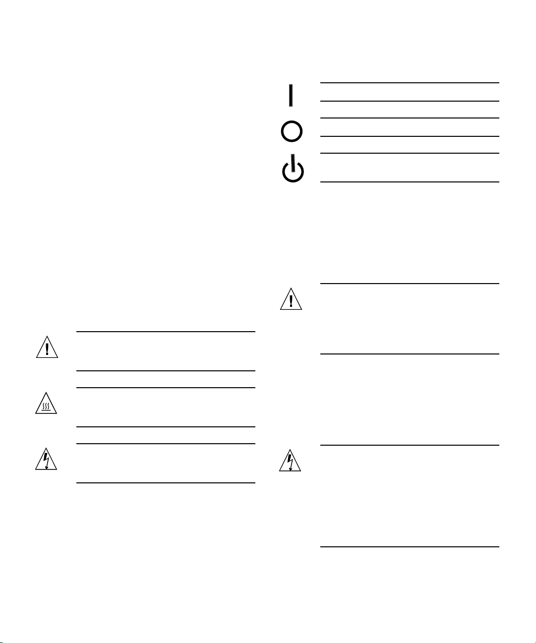
Symbols
The following symbols may appear in this book:
Caution – There is a risk of personal injury
and equipment damage. Follow the
instructions.
Depending on the type of power switch your device has,
one of the following symbols may be used:
On – Applies AC power to the system.
Off – Removes AC power from the system.
Standby – The On/Standby switch is in the
standby position.
Modifications to Equipment
Do not make mechanical or electrical modifications to the
equipment. Sun Microsystems is not responsible for
regulatory compliance of a modified Sun product.
Placement of a Sun Product
Caution – Do not block or cover the openings
of your Sun product. Never place a Sun
product near a radiator or heat register.
Failure to follow these guidelines can cause
overheating and affect the reliability of your
Sun product.
Caution – Hot surface. Avoid contact.
Surfaces are hot and may cause personal
injury if touched.
Caution – Hazardous voltages are present. To
reduce the risk of electric shock and danger to
personal health, follow the instructions.
SELV Compliance
Safety status of I/O connections comply to SELV
requirements.
Power Cord Connection
Caution – Sun products are designed to work
with power systems having a grounded
neutral (grounded return for DC-powered
products). To reduce the risk of electric shock,
do not plug Sun products into any other type
of power system. Contact your facilities
manager or a qualified electrician if you are
not sure what type of power is supplied to
your building.
xiii
Page 14
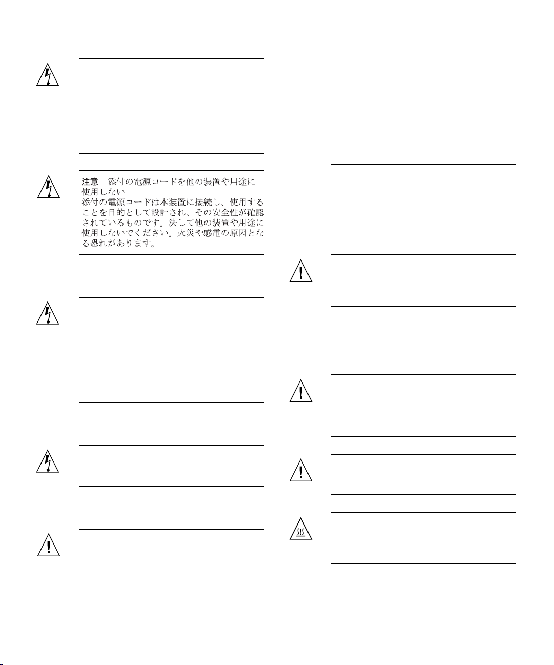
Caution – Not all power cords have the same
current ratings. Do not use the power cord
provided with your equipment for any other
products or use. Household extension cords
do not have overload protection and are not
meant for use with computer systems. Do not
use household extension cords with your Sun
product.
instructions provided in the product service
manual. Do not disassemble batteries or
attempt to recharge them outside the system.
Do not dispose of batteries in fire. Dispose of
batteries properly in accordance with the
manufacturer’s instructions and local
regulations. Note that on Sun CPU boards,
there is a lithium battery molded into the realtime clock. These batteries are not customer
replaceable parts.
System Unit Cover
You must remove the cover of your Sun computer system
unit to add cards, memory, or internal storage devices. Be
sure toreplace the cover before powering on yourcomputer
system.
The following caution applies only to devices with a
Standby power switch:
Caution – The power switch of this product
functions as a standby type device only. The
power cord serves as the primary disconnect
device for the system. Be sure to plug the
power cord into a grounded power outlet that
is nearby the system and is readily accessible.
Do not connect the power cord when the
power supply has been removed from the
system chassis.
The followingcaution applies only to deviceswith multiple
power cords:
Caution – For products with multiple power
cords, all power cords must be disconnected
to completely remove power from the system.
Battery Warning
Caution – There is danger of explosion if
batteries are mishandled or incorrectly
replaced. On systems with replaceable
batteries, replace only with the same
manufacturer and type or equivalent type
recommended by the manufacturer per the
Caution – Do not operate Sun products
without the cover in place. Failure to take this
precaution may result in personal injury and
system damage.
Rack System Warning
The following warnings apply to Racks and Rack Mounted
systems.
Caution – For safety, equipment should
always be loaded from the bottom up. That is,
install the equipment that will be mounted in
the lowest part of the rack first, then the next
higher systems, etc.
Caution – To prevent the rack from tipping
during equipment installation, the anti-tilt bar
on the rack must be deployed.
Caution – To prevent extreme operating
temperature within the rack insure that the
maximum temperature does not exceed the
product’s ambient rated temperatures.
xiv Sun PCI-Express Dual Gigabit Ethernet MMF/UTP Adapter Installation and User’s Guide • June 2006
Page 15
Caution – To prevent extreme operating
temperatures due to reduced airflow
consideration should be made to the amount
of air flow that is required for a safe operation
of the equipment.
Laser Compliance Notice
Sun products that use laser technology comply withClass 1
laser requirements.
Class 1 Laser Product
Luokan 1 Laserlaite
Klasse 1 Laser Apparat
Laser Klasse 1
CD and DVD Devices
The following caution applies to CD, DVD, and other
optical devices.
■ Assurez-vous que la tension et la fréquence de votre
source d'alimentation correspondent à la tension et à
la fréquence indiquées sur l'étiquette de la tension
électrique nominale du matériel
■ N'introduisez jamais d'objets quels qu'ils soient dans
les ouvertures de l'équipement. Vous pourriez vous
trouver en présence de hautes tensions dangereuses.
Tout objet étranger conducteur risque de produire un
court-circuit pouvant présenter un risque d'incendie
ou de décharge électrique, ou susceptible
d'endommager le matériel.
Caution – Use of controls, adjustments, or the
performance of procedures other than those
specified herein may result in hazardous
radiation exposure.
Conformité aux normes de sécurité
Veuillez lire attentivement cette section avant de
commencer. Ce texte traite des mesures de sécurité qu’il
convient de prendre pour l’installation d’un produit Sun
Microsystems.
Mesures de sécurité
Pour votre sécurité, nous vous recommandons de suivre
scrupuleusement lesmesures de sécuritéci-dessous lorsque
vous installez votre matériel:
■ Suivez tous les avertissements et toutes les
instructions inscrites sur le matériel.
Safety Agency Compliance Statement xv
Page 16
Symboles
Vous trouverez ci-dessous la signification des différents
symboles utilisés:
Attention – Vous risquez d'endommager le
matériel ou de vous blesser. Veuillez suivre les
instructions.
Attention – Surfaces brûlantes. Evitez tout
contact. Les surfaces sont brûlantes. Vous
risquez de vous blesser si vous les touchez.
Attention – Tensions dangereuses. Pour
réduire les risques de décharge électrique et
de danger physique, observez les consignes
indiquées.
Selon le type d'interrupteur marche/arrêt dont votre
appareil est équipé, l'un des symboles suivants sera utilisé:
Marche – Met le système sous tension
alternative.
Arret – Met le système hors tension
alternative.
Positionnement d’un produit Sun
Attention – Evitez d'obstruer ou de recouvrir
les orifices de votre produit Sun. N'installez
jamais un produit Sun près d'un radiateur ou
d'une source de chaleur. Si vous ne respectez
pas ces consignes, votre produit Sun risque de
surchauffer et son fonctionnement en sera
altéré.
Conformité SELV
Le niveau de sécurité des connexions E/S est conforme aux
normes SELV.
Connexion du cordon d’alimentation
Attention – Les produits Sun sont conçus
pour fonctionner avec des systèmes
d'alimentation équipés d'un conducteur
neutre relié à la terre (conducteur neutre pour
produits alimentés en CC). Pour réduire les
risques de décharge électrique, ne branchez
jamais les produits Sun sur une source
d'alimentation d'un autre type. Contactez le
gérant de votre bâtiment ou un électricien
agréé si vous avez le moindre doute quant au
type d'alimentation fourni dans votre
bâtiment.
Veilleuse – L'interrupteur Marche/Veille est
sur la position de veille.
Modification du matériel
N'apportez aucune modification mécanique ou électrique
au matériel. Sun Microsystems décline toute responsabilité
quant à la non-conformité éventuelle d'un produit Sun
modifié.
xvi Sun PCI-Express Dual Gigabit Ethernet MMF/UTP Adapter Installation and User’s Guide • June 2006
Attention – Tous les cordons d'alimentation
ne présentent pas les mêmes caractéristiques
électriques. Les cordons d'alimentation à
usage domestique ne sont pas protégés contre
les surtensions et ne sont pas conçus pour être
utilisés avec des ordinateurs. N'utilisez jamais
de cordon d'alimentation à usage domestique
avec les produits Sun.
Page 17
L'avertissement suivant s'applique uniquement aux
systèmes équipés d'un interrupteur Veille:
Attention – L'interrupteur d'alimentation de
ce produit fonctionne uniquement comme un
dispositif de mise en veille. Le cordon
d'alimentation constitue le moyen principal de
déconnexion de l'alimentation pour le
système. Assurez-vous de le brancher dans
une prise d'alimentation mise à la terre près
du système et facile d'accès. Ne le branchez
pas lorsque l'alimentation électrique ne se
trouve pas dans le châssis du système.
Couvercle de l'unité
Pour ajouterdes cartes,de la mémoire ou des périphériques
de stockage internes, vous devez retirer le couvercle de
votre système Sun. Remettez le couvercle supérieur en
place avant de mettre votre système sous tension.
Attention – Ne mettez jamais des produits
Sun sous tension si leur couvercle supérieur
n'est pas mis en place. Si vous ne prenez pas
ces précautions, vous risquez de vous blesser
ou d'endommager le système.
L'avertissement suivant s'applique uniquement aux
systèmes équipés de plusieurs cordons d'alimentation:
Attention – Pour mettre un système équipé de
plusieurs cordons d'alimentation hors tension,
il est nécessaire de débrancher tous les
cordons d'alimentation.
Mise en garde relative aux batteries
Attention – Les batteries risquent d’exploser
en cas de manipulation maladroite ou de
remplacement incorrect. Pour les systèmes
dont les batteries sont remplaçables, effectuez
les remplacements uniquement selon le
modèle du fabricant ou un modèle équivalent
recommandé par le fabricant, conformément
aux instructions fournies dans le manuel de
service du système. N’essayez en aucun cas de
démonter les batteries, ni de les recharger hors
du système. Ne les jetez pas au feu. Mettez-les
au rebut selon les instructions du fabricant et
conformément à la législation locale en
vigueur. Notez que sur les cartes processeur
de Sun, une batterie au lithium a été moulée
dans l'horloge temps réel. Les batteries ne sont
pas des pièces remplaçables par le client.
Mise en garde relative au système en rack
La mise en garde suivante s'applique aux racks et aux
systèmes montés en rack.
Attention – Pour des raisons de sécurité, le
matériel doit toujours être chargé du bas vers
le haut. En d'autres termes, vous devez
installer, en premier, le matériel qui doit se
trouver dans la partie la plus inférieure du
rack, puis installer le matériel sur le niveau
suivant, etc.
Attention – Afin d'éviter que le rack ne
penche pendant l'installation du matériel, tirez
la barre anti-basculement du rack.
Attention – Pour éviter des températures de
fonctionnement extrêmes dans le rack,
assurez-vous que la température maximale ne
dépasse pas la fourchette de températures
ambiantes du produit déterminée par le
fabricant.
Attention – Afin d'empêcher des
températures de fonctionnement extrêmes
provoquées par une aération insuffisante,
assurez-vous de fournir une aération
appropriée pour un fonctionnement du
matériel en toute sécurité
Safety Agency Compliance Statement xvii
Page 18
Avis de conformité des appareils laser
Les produitsSun quifont appelaux technologieslasers sont
conformes aux normes de la classe 1 en la matière.
Class 1 Laser Product
Luokan 1 Laserlaite
Klasse 1 Laser Apparat
Laser Klasse 1
Symbole
Die Symbole in diesem Handbuch haben folgende
Bedeutung:
Achtung – Gefahr von Verletzung und
Geräteschaden. Befolgen Sie die Anweisungen.
Achtung – Heiße Oberfläche. Nicht berühren,
da Verletzungsgefahr durch heiße Oberfläche
besteht.
Périphériques CD et DVD
L'avertissement suivant s'applique aux périphériques CD,
DVD et autres périphériques optiques:
Attention – L'utilisation de contrôles et de
réglages ou l'application de procédures autres
que ceux spécifiés dans le présent document
peuvent entraîner une exposition à des
radiations dangereuses.
Einhaltung sicherheitsbehördlicher
Vorschriften
Lesen Sie vor dem Ausführen von Arbeiten diesen
Abschnitt. Im folgenden Text werden Sicherheitsvorkehrungen beschrieben, die Sie bei der Installation eines
Sun Microsystems-Produkts beachten müssen.
Sicherheitsvorkehrungen
Treffen Sie zu Ihrem eigenen Schutzbei der Installation des
Geräts die folgenden Sicherheitsvorkehrungen:
■ Beachten Sie alle auf den Geräten angebrachten
Warnhinweise und Anweisungen.
■ Stellen Sie sicher, dass Spannung und Frequenz der
Stromversorgung den Nennleistungen auf dem am
Gerät angebrachten Etikett entsprechen.
■ Führen Sie niemals Fremdobjekte in die Öffnungen
am Gerät ein. Es können gefährliche Spannungen
anliegen. Leitfähige Fremdobjekte können einen
Kurzschluss verursachen, der einen Brand, Stromschlag oder Geräteschaden herbeiführen kann.
Achtung – Gefährliche Spannungen. Befolgen
Sie die Anweisungen, um Stromschläge und
Verletzungen zu vermeiden.
Je nach Netzschaltertyp an Ihrem Gerät kann eines der
folgenden Symbole verwendet werden:
Ein – Versorgt das System mit Wechselstrom.
Aus– Unterbricht die Wechselstromzufuhr
zum Gerät.
Wartezustand – Der Ein-/Standby-Netzschalter befindet sich in der Standby-Position.
Modifikationen des Geräts
Nehmen Sie keine elektrischen oder mechanischen
Gerätemodifikationen vor. Sun Microsystems ist für die
Einhaltung der Sicherheitsvorschriften von modifizierten
Sun-Produkten nicht haftbar.
xviii Sun PCI-Express Dual Gigabit Ethernet MMF/UTP Adapter Installation and User’s Guide • June 2006
Page 19
Aufstellung von Sun-Geräten
Achtung – Geräteöffnungen Ihres SunProdukts dürfen nicht blockiert oder
abgedeckt werden. Sun-Geräte sollten niemals
in der Nähe von Heizkörpern oder Heißluftklappen aufgestellt werden. Die Nichtbeachtung dieser Richtlinien kann Überhitzung
verursachen und die Zuverlässigkeit Ihres
Sun-Geräts beeinträchtigen.
SELV-Konformität
Der Sicherheitsstatus der E/A-Verbindungen entspricht
den SELV-Anforderungen.
Anschluss des Netzkabels
Achtung – Sun-Geräte sind für
Stromversorgungssysteme mit einem
geerdeten neutralen Leiter (geerdeter
Rückleiter bei gleichstrombetriebenen
Geräten) ausgelegt. Um die Gefahr von
Stromschlägen zu vermeiden, schließen Sie
das Gerät niemals an andere Stromversorgungssysteme an. Wenden Sie sich an den
zuständigen Gebäudeverwalter oder an einen
qualifizierten Elektriker, wenn Sie nicht sicher
wissen, an welche Art von Stromversorgungssystem Ihr Gebäude angeschlossen ist.
Achtung – Nicht alle Netzkabel verfügen
über die gleichen Nennwerte. Herkömmliche,
im Haushalt verwendete Verlängerungskabel
besitzen keinen Überlastschutz und sind
daher für Computersysteme nicht geeignet.
Verwenden Sie bei Ihrem Sun-Produkt keine
Haushalts-Verlängerungskabel.
Netzkabel an eine frei zugängliche geerdete
Steckdose in der Nähe des Systems angeschlossen ist. Schließen Sie das Stromkabel
nicht an, wenn die Stromversorgung vom
Systemchassis entfernt wurde.
Die folgende Warnung gilt nur für Geräte mit mehreren
Netzkabeln:
Achtung – Bei Produkten mit mehreren Netzkabeln müssen alle Netzkabel abgetrennt werden, um das System völlig von der Stromversorgung zu trennen.
Warnung bezüglich Batterien
Achtung – Bei unsachgemäßer Handhabung
oder nicht fachgerechtem Austausch der
Batterien besteht Explosionsgefahr. Verwenden Sie bei Systemen mit austauschbaren
Batterien ausschließlich Ersatzbatterien
desselben Typs und Herstellers bzw. einen
entsprechenden, vom Hersteller gemäß den
Anweisungen im Service-Handbuch des
Produkts empfohlenen Batterietyp. Versuchen
Sie nicht, die Batterien auszubauen oder
außerhalb des Systems wiederaufzuladen.
Werfen Sie die Batterien nicht ins Feuer.
Entsorgen Sie die Batterien entsprechend den
Anweisungen des Herstellers und den vor Ort
geltenden Vorschriften. CPU-Karten von Sun
verfügen über eine Echtzeituhr mit integrierter Lithiumbatterie. Diese Batterie darf nur
von einem qualifizierten Servicetechniker ausgewechselt werden.
Die folgende Warnung gilt nur für Geräte mit StandbyNetzschalter:
Achtung – Beim Netzschalter dieses Geräts
handelt es sich nur um einen Ein/StandbySchalter. Zum völligen Abtrennen des Systems
von der Stromversorgung dient hauptsächlich
das Netzkabel. Stellen Sie sicher, dass das
Safety Agency Compliance Statement xix
Page 20
Gehäuseabdeckung
Sie müssen die Abdeckung Ihres Sun-Computersystems
entfernen, um Karten, Speicher oderinterne Speichergeräte
hinzuzufügen. Bringen Sie vor dem Einschalten des
Systems die Gehäuseabdeckung wieder an.
Hinweis zur Laser-Konformität
Sun-Produkte, die die Laser-Technologie verwenden,
entsprechen den Laser-Anforderungen der Klasse 1.
Achtung – Nehmen Sie Sun-Geräte nicht ohne
Abdeckung in Betrieb. Die Nichtbeachtung
dieses Warnhinweises kann Verletzungen oder
Geräteschaden zur Folge haben.
Warnungen bezüglich in Racks eingebauter
Systeme
Die folgenden Warnungen gelten für Racks und in Racks
eingebaute Systeme:
Achtung – Aus Sicherheitsgründen sollten
sämtliche Geräte von unten nach oben in
Racks eingebaut werden. Installieren Sie also
zuerst die Geräte, die an der untersten
Position im Rack eingebaut werden, gefolgt
von den Systemen, die an nächsthöherer Stelle
eingebaut werden, usw.
Achtung – Verwenden Sie beim Einbau den
Kippschutz am Rack, um ein Umkippen zu
vermeiden.
Achtung – Um extreme Betriebstemperaturen
im Rack zu vermeiden, stellen Sie sicher, dass
die Maximaltemperatur die Nennleistung der
Umgebungstemperatur für das Produkt nicht
überschreitet
Achtung – Um extreme Betriebstemperaturen
durch verringerte Luftzirkulation zu vermeiden, sollte die für den sicheren Betrieb des
Geräts erforderliche Luftzirkulation eingesetzt
werden.
Class 1 Laser Product
Luokan 1 Laserlaite
Klasse 1 Laser Apparat
Laser Klasse 1
CD- und DVD-Geräte
Die folgende Warnung gilt für CD-, DVD- und andere
optische Geräte:
Achtung – Die hier nicht aufgeführte
Verwendung von Steuerelementen,
Anpassungen oder Ausführung von
Vorgängen kann eine gefährliche
Strahlenbelastung verursachen.
Normativas de seguridad
Lea esta sección antes de realizar cualquier operación. En
ella seexplican las medidasde seguridad que debe tomaral
instalar un producto de Sun Microsystems.
Medidas de seguridad
Para su protección, tome las medidas de seguridad
siguientes durante la instalación del equipo:
■ Siga todos los avisos e instrucciones indicados en el
equipo.
■ Asegúrese de que el voltaje y frecuencia de la fuente
de alimentación coincidan con el voltaje y frecuencia
indicados en la etiqueta de clasificación eléctrica del
equipo.
■ No introduzca objetos de ningún tipo por las rejillas
del equipo, ya que puede quedar expuesto a voltajes
peligrosos. Los objetos conductores extraños pueden
producir cortocircuitos y, en consecuencia, incendios,
descargas eléctricas o daños en el equipo.
xx Sun PCI-Express Dual Gigabit Ethernet MMF/UTP Adapter Installation and User’s Guide • June 2006
Page 21
Símbolos
En este documento aparecen los siguientes símbolos:
Precaución – Existe el riesgo de que se
produzcan lesiones personales y daños en el
equipo. Siga las instrucciones.
Precaución – Superficie caliente. Evite todo
contacto. Las superficies están calientes y
pueden causar lesiones personales si se tocan.
Precaución – Voltaje peligroso. Para reducir
el riesgo de descargas eléctricas y lesiones
personales, siga las instrucciones.
En función del tipo de interruptor de alimentación del que
disponga el dispositivo, se utilizará uno de los símbolos
siguientes:
Encendido – Suministra alimentación de CA
al sistema.
Apagado – Corta la alimentación de CA del
sistema.
Espera – El interruptor de encendido/espera
está en la posición de espera.
Colocación de un producto Sun
Precaución – No obstruya ni tape las rejillas
del producto Sun. Nunca coloque un producto
Sun cerca de radiadores ni fuentes de calor. Si
no sigue estas indicaciones, el producto Sun
podría sobrecalentarse y la fiabilidad de su
funcionamiento se vería afectada.
Cumplimiento de la normativa para
instalaciones SELV
Las condiciones de seguridad de las conexiones de entrada
y salidacumplen losrequisitos para instalaciones SELV (del
inglés Safe Extra Low Voltage, voltaje bajo y seguro).
Conexión del cable de alimentación
Precaución – Los productos Sun se han
diseñado para funcionar con sistemas de
alimentación que cuenten con un conductor
neutro a tierra (con conexión a tierra de
regreso para los productos con alimentación
de CC). Para reducir el riesgo de descargas
eléctricas, no conecte ningún producto Sun a
otro tipo de sistema de alimentación. Póngase
en contacto con el encargado de las
instalaciones de su empresa o con un
electricista cualificado en caso de que no esté
seguro del tipo de alimentación del que se
dispone en el edificio.
Modificaciones en el equipo
No realicemodificaciones de tipo mecánico ni eléctrico en el
equipo. Sun Microsystems no se hace responsable del
cumplimiento de normativas en caso de que un producto
Sun se haya modificado.
Precaución – No todos los cables de
alimentación tienen la misma clasificación
eléctrica. Los alargadores de uso doméstico no
cuentan con protección frente a sobrecargas y
no están diseñados para su utilización con
sistemas informáticos. No utilice alargadores
de uso doméstico con el producto Sun.
La siguiente medida solamente se aplica a aquellos
dispositivos que dispongan de un interruptor de
alimentación de espera:
Precaución – El interruptor de alimentación
de este producto funciona solamente como un
dispositivo de espera. El cable de alimentación
Safety Agency Compliance Statement xxi
Page 22
hace las veces de dispositivo de desconexión
principal del sistema. Asegúrese de que
conecta el cable de alimentación a una toma
de tierra situada cerca del sistema y de fácil
acceso. No conecte el cable de alimentación si
la unidad de alimentación no se encuentra en
el bastidor del sistema.
La siguiente medida solamente se aplica a aquellos
dispositivos que dispongan de varios cables de
alimentación:
Precaución – No ponga en funcionamiento
los productos Sun que no tengan colocada la
cubierta. De lo contrario, puede sufrir lesiones
personales y ocasionar daños en el sistema.
Advertencia sobre el sistema en bastidor
Las advertencias siguientes se aplican a los sistemas
montados en bastidor y a los propios bastidores.
Precaución – En los productos que cuentan
con varios cables de alimentación, debe
desconectar todos los cables de alimentación
para cortar por completo la alimentación
eléctrica del sistema.
Advertencia sobre las baterías
Precaución – Si las baterías no se manipulan
o reemplazan correctamente, se corre el riesgo
de que estallen. En los sistemas que cuentan
con baterías reemplazables, reemplácelas sólo
con baterías del mismo fabricante y el mismo
tipo, o un tipo equivalente recomendado por
el fabricante, de acuerdo con las instrucciones
descritas en el manual de servicio del
producto. No desmonte las baterías ni intente
recargarlas fuera del sistema. No intente
deshacerse de las baterías echándolas al fuego.
Deshágase de las baterías correctamente de
acuerdo con las instrucciones del fabricante y
las normas locales. Tenga en cuenta que en las
placas CPU de Sun, hay una batería de litio
incorporada en el reloj en tiempo real. Los
usuarios no deben reemplazar este tipo de
baterías.
Precaución – Por seguridad, siempre deben
montarse los equipos de abajo arriba. A saber,
primero debe instalarse el equipo que se
situará en el bastidor inferior; a continuación,
el que se situará en el siguiente nivel, etc.
Precaución – Para evitar que el bastidor se
vuelque durante la instalación del equipo,
debe extenderse la barra antivolcado del
bastidor.
Precaución – Para evitar que se alcance una
temperatura de funcionamiento extrema en el
bastidor, asegúrese de que la temperatura
máxima no sea superior a la temperatura
ambiente establecida como adecuada para el
producto.
Precaución – Para evitar que se alcance una
temperatura de funcionamiento extrema
debido a una circulación de aire reducida,
debe considerarse la magnitud de la
circulación de aire requerida para que el
equipo funcione de forma segura.
Cubierta de la unidad del sistema
Debe extraer la cubierta de la unidad del sistema
informático Sun para instalar tarjetas, memoria o
dispositivos de almacenamiento internos. Vuelva a colocar
la cubierta antes de encender el sistema informático.
xxii Sun PCI-Express Dual Gigabit Ethernet MMF/UTP Adapter Installation and User’s Guide • June 2006
Page 23
Aviso de cumplimiento de la normativa para
la utilización de láser
Los productos Sunque utilizantecnología lásercumplen los
requisitos establecidos para los productos láser de clase 1.
Class 1 Laser Product
Luokan 1 Laserlaite
Klasse 1 Laser Apparat
Laser Klasse 1
Dispositivos de CD y DVD
La siguiente medida se aplica a los dispositivos de CD y
DVD, así como a otros dispositivos ópticos:
Precaución – La utilización de controles,
ajustes o procedimientos distintos a los aquí
especificados puede dar lugar a niveles de
radiación peligrosos.
Nordic Lithium Battery Cautions
Danmark
Advarsel! – Litiumbatteri — Eksplosionsfare
ved fejlagtig håndtering. Udskiftning må kun
ske med batteri af samme fabrikat og type.
Levér det brugte batteri tilbage til
leverandøren.
Suomi
Varoitus – Paristo voi räjähtää, jos se on
virheellisesti asennettu. Vaihda paristo
ainoastaan laitevalmistajan suosittelemaan
tyyppiin. Hävitä käytetty paristo valmistajan
ohjeiden mukaisesti.
Norge
Sverige
Advarsel – Litiumbatteri — Eksplosjonsfare.
Ved utskifting benyttes kun batteri som
anbefalt av apparatfabrikanten. Brukt batteri
returneres apparatleverandøren.
Varning – Explosionsfara vid felaktigt
batteribyte. Använd samma batterityp eller en
ekvivalent typ som rekommenderas av
apparattillverkaren. Kassera använt batteri
enligt fabrikantens instruktion.
Safety Agency Compliance Statement xxiii
Page 24

xxiv Sun PCI-Express Dual Gigabit Ethernet MMF/UTP Adapter Installation and User’s Guide • June 2006
Page 25

Declaration of Conformity
Compliance Model Number: 3008
Product Family Name: Sun PCI-E Dual Gigabit Ethernet MMF (X7280A)
EMC
USA—FCC Class B
This equipment complies with Part 15 of the FCC Rules. Operation is subject to the following two conditions:
1. This equipment may not cause harmful interference.
2. This equipment must accept any interference that may cause undesired operation.
European Union
This equipment complies with the following requirements of the EMC Directive 89/336/EEC:
As Telecommunication Network Equipment (TNE) in Both Telecom Centers and Other Than Telecom Centers per (as applicable):
EN 300 386 V1.3.2 (2003-05) Required Limits:
EN55022/CISPR22 ClassB
EN61000-3-2:2000 Pass
EN61000-3-3:1995 +A1:2000 Pass
EN61000-4-2 6 kV (Direct), 8 kV (Air)
EN61000-4-3 3 V/m 80-1000MHz, 10 V/m 800-960 MHz, and 1400-2000 MHz
EN61000-4-4 1 kV AC and DC Power Lines, 0.5 kV Signal Lines
EN61000-4-5 2 kV AC Line-Gnd, 1 kV AC Line-Line and Outdoor Signal Lines, 0.5 kV Indoor Signal Lines >
EN61000-4-6 3 V
EN61000-4-11 Pass
As Information Technology Equipment (ITE) Class B per (as applicable):
EN 55022:1994 +A1:1995 +A2:1997 Class B
EN 61000-3-2:2000 Pass
EN 61000-3-3:1995 +A1:2000 Pass
EN55024:1998 Required Limits:
EN61000-4-2 4 kV (Direct), 8 kV (Air)
EN61000-4-3 3 V/m
EN61000-4-4 1 kV AC Power Lines, 0.5 kV Signal and DC Power Lines
EN61000-4-5 1 kV AC Line-Line and Outdoor Signal Lines, 2 kV AC Line-Gnd, 0.5 kV DC Power Lines
EN61000-4-6 3 V
EN61000-4-8 1 A/m
EN61000-4-11 Pass
10m
Safety: This equipment complies with the following requirements of the Low Voltage Directive 73/23/EEC:
EC Type Examination Certificates:
EN 60950-1:2001, 1st Edition TÜV Rheinland Certificate No.
IEC 60950-1:2001, 1st Edition CB Scheme Certificate No.
Evaluated to all CB Countries
UL and cUL/CSA 60950-1:2003, CSA C22.2 No. 60950-01-03 File: Vol. Sec.
Supplementary Information: This product was tested and complies with all the requirements for the CE Mark.
This equipment complies with the Restriction of Hazardous Substances (RoHS) directive 2002/95/EC.
/S/ /S/
Dennis P. Symanski DATE
Manager, Compliance Engineering
Sun Microsystems, Inc.
4150 Network Circle, MPK15-102
Santa Clara, CA 95054 U.S.A
Tel: 650-786-3255
Fax: 650-786-3723
Pamela J. Dullaghan DATE
Quality Program Manager
Sun Microsystems Scotland, Limited
Springfield, Linlithgow
West Lothian, EH49 7LR
Scotland, United Kingdom
Tel: +44 1 506 672 395 Fax: +44 1 506 670 011
xxv
Page 26

xxvi Sun PCI-Express Dual Gigabit Ethernet MMF/UTP Adapter Installation and User’s Guide • June 2006
Page 27

Declaration of Conformity
Compliance Model Number: 3009
Product Family Name: Sun PCI-E Dual Gigabit Ethernet UTP (X7281A)
EMC
USA—FCC Class B
This equipment complies with Part 15 of the FCC Rules. Operation is subject to the following two conditions:
1. This equipment may not cause harmful interference.
2. This equipment must accept any interference that may cause undesired operation.
European Union
This equipment complies with the following requirements of the EMC Directive 89/336/EEC:
As Telecommunication Network Equipment (TNE) in Both Telecom Centers and Other Than Telecom Centers per (as applicable):
EN 300 386 V1.3.2 (2003-05) Required Limits:
EN 55022:1994 +A1:1995
+A2:1997
EN61000-3-2:2000 Pass
EN61000-3-3:1995 +A1:2000 Pass
EN61000-4-2 6 kV (Direct), 8 kV (Air)
EN61000-4-3 3 V/m 80-1000MHz, 10 V/m 800-960 MHz, and 1400-2000 MHz
EN61000-4-4 1 kV AC and DC Power Lines, 0.5 kV Signal Lines
EN61000-4-5 2 kV AC Line-Gnd, 1 kV AC Line-Line and Outdoor Signal Lines, 0.5 kV Indoor Signal Lines > 10m
EN61000-4-6 3 V
EN61000-4-11 Pass
As Information Technology Equipment (ITE) Class B per (as applicable):
EN 55022:1994 +A1:1995 +A2:1997 Class B
EN 61000-3-2:2000 Pass
EN 61000-3-3:1995 +A1:2000 Pass
EN55024:1998 Required Limits:
EN61000-4-2 4 kV (Direct), 8 kV (Air)
EN61000-4-3 3 V/m
EN61000-4-4 1 kV AC Power Lines, 0.5 kV Signal and DC Power Lines
EN61000-4-5 1 kV AC Line-Line and Outdoor Signal Lines, 2 kV AC Line-Gnd, 0.5 kV DC Power Lines
EN61000-4-6 3 V
EN61000-4-8 1 A/m
EN61000-4-11 Pass
ClassB
Safety: This equipment complies with the following requirements of the Low Voltage Directive 73/23/EEC:
EC Type Examination Certificates:
EN 60950-1:2001, 1st Edition TÜV Rheinland Certificate No.
IEC 60950-1:2001, 1st Edition CB Scheme Certificate No.
Evaluated to all CB Countries
UL and cUL/CSA 60950-1:2003, CSA C22.2 No. 60950-01-03 File: Vol. Sec.
Supplementary Information: This product was tested and complies with all the requirements for the CE Mark.
This equipment complies with the Restriction of Hazardous Substances (RoHS) directive 2002/95/EC.
/S/ /S/
Dennis P. Symanski DATE
Manager, Compliance Engineering
Sun Microsystems, Inc.
4150 Network Circle, MPK15-102
Santa Clara, CA 95054 U.S.A
Tel: 650-786-3255
Fax: 650-786-3723
Pamela J. Dullaghan DATE
Quality Program Manager
Sun Microsystems Scotland, Limited
Springfield, Linlithgow
West Lothian, EH49 7LR
Scotland, United Kingdom
Tel: +44 1 506 672 395 Fax: +44 1 506 670 011
xxvii
Page 28

xxviii Sun PCI-Express Dual Gigabit Ethernet MMF/UTP Adapter Installation and User’s Guide • June 2006
Page 29

Preface
The Sun™ PCI-Express Dual Gigabit Ethernet adapters consist of four cards:
■ Sun PCI-Express Dual Gigabit Ethernet UTP Low Profile card
■ Sun PCI-Express Dual Gigabit Ethernet MMF Low Profile card
■ Sun PCI-Express Dual Gigabit Ethernet UTP ExpressModule
■ Sun PCI-Express Dual Gigabit Ethernet MMF ExpressModule
The Sun PCI-Express Dual Gigabit Ethernet Adapter Installation and User’s Guide
provides installation instructions for all four cards. This manual also describes how
to configure the driver software for the ipge driver used in SPARC® systems, the
e1000 driver used in Linux x86 systems, and the e1000g driver used in Solaris x86
systems.
These instructions are designed for enterprise system administrators with experience
installing network hardware and software.
Note – In this document the term x86 refers to 64-bit and 32-bit systems
manufactured using processors compatible with the AMD64 or Intel Xeon/Pentium
product families. For supported systems, see the Solaris Hardware Compatibility Guide.
How This Document Is Organized
Chapter 1 describes the Sun PCI-Express Dual Gigabit Ethernet adapter hardware
and software.
Chapter 2 describes how to install the adapter in your system and verify that it has
been installed correctly.
Chapter 3 describes how to configure ipge and e1000 device driver parameters.
xxix
Page 30

Chapter 4 describes how to configure the e1000g driver parameters.
Chapter 5 explains virtual local area networks (VLANs) and provides configuration
instructions and examples.
Appendix A lists the specifications for the Sun PCI-Express Dual Gigabit Ethernet
adapter.
Appendix B provides an overview of the SunVTS diagnostic application and
instructions for updating the SunVTS software to recognize the adapter.
Appendix C explains how to install the driver software in a Linux environment.
Appendix D explains how to install and configure the driver software in x86
environments.
Using UNIX Commands
This document might not contain information about basic UNIX®commands and
procedures such as shutting down the system, booting the system, and configuring
devices. Refer to the following for this information:
■ Software documentation that you received with your system
■ Solaris™ Operating System documentation, which is at:
http://docs.sun.com
xxx Sun PCI-Express Dual Gigabit Ethernet MMF/UTP Adapter Installation and User’s Guide • June 2006
Page 31

Typographic Conventions
Typeface
AaBbCc123 The names of commands, files,
AaBbCc123 What you type, when contrasted
AaBbCc123 Book titles, new words or terms,
* The settings on your browser might differ from these settings.
*
Meaning Examples
Edit your.login file.
and directories; on-screen
computer output
with on-screen computer output
words to be emphasized.
Replace command-line variables
with real names or values.
Use ls -a to list all files.
% You have mail.
su
%
Password:
Read Chapter 6 in the User’s Guide.
These are called class options.
Yo u must be superuser to do this.
To delete a file, type rm filename.
Shell Prompts
Shell Prompt
C shell machine-name%
C shell superuser machine-name#
Bourne shell and Korn shell $
Bourne shell and Korn shell superuser #
Preface xxxi
Page 32

Related Documentation
The documents listed as online are available at:
http://www.sun.com/documentation
Application Title Part Number Format Location
Release Notes Sun PCI-Express Dual Gigabit Ethernet Adapter
Release Notes
Safety and
compliance
Safety and Compliance Manual 816-7190 PDF
819-4091 PDF
HTML
HTML
Online
Online
Documentation, Support, and Training
Sun Function URL
Documentation http://www.sun.com/documentation/
Support http://www.sun.com/support/
Training http://www.sun.com/training/
Third-Party Web Sites
Sun is not responsible for the availability of third-party web sites mentioned in this
document. Sun does not endorse and is not responsible or liable for any content,
advertising, products, or other materials that are available on or through such sites
or resources. Sun will not be responsible or liable for any actual or alleged damage
or loss caused by or in connection with the use of or reliance on any such content,
goods, or services that are available on or through such sites or resources.
xxxii Sun PCI-Express Dual Gigabit Ethernet MMF/UTP Adapter Installation and User’s Guide • June 2006
Page 33

Sun Welcomes Your Comments
Sun is interested in improving its documentation and welcomes your comments and
suggestions. You can submit your comments by going to:
http://www.sun.com/hwdocs/feedback
Please include the title and part number of your document with your feedback:
Sun PCI-Express Dual Gigabit Ethernet MMF/UTP Adapter Installation and User’s Guide,
part number 819-4090-10
Preface xxxiii
Page 34

xxxiv Sun PCI-Express Dual Gigabit Ethernet MMF/UTP Adapter Installation and User’s Guide • June 2006
Page 35

CHAPTER
1
Sun PCI-Express Dual Gigabit Ethernet Adapter Overview
This chapter describes the Sun PCI-Express Dual Gigabit Ethernet hardware and
software, and includes the following sections:
■ “Hardware Overview” on page 1
■ “ExpressModule Hardware and Software Requirements” on page 8
■ “Patches and Updates” on page 9
■ “Features of the Sun PCI-Express Dual Gigabit Ethernet MMF Low-Profile
Adapter” on page 9
■ “Features of the Sun PCI-Express Dual Gigabit Ethernet UTP Low-Profile
Adapter” on page 10
■ “Features of the Sun PCI-Express Dual Gigabit Ethernet MMF ExpressModule” on
page 10
■ “Features of the Sun PCI-Express Dual Gigabit Ethernet UTP ExpressModule” on
page 11
Hardware Overview
The adapter provides a high-performance, highly integrated Ethernet LAN adapter
for PCI-Express systems using x4 PCI-E.
1
Page 36

Sun PCI-Express Dual Gigabit Ethernet MMF Low-Profile Adapter
The Sun PCI-Express Dual Gigabit Ethernet MMF adapter is a low-profile, dual-port
Gigabit Ethernet fiber-optics PCI-Express adapter. It operates in 10/100/1000
Mbit/sec Ethernet networks.
FIGURE 1-1 Sun PCI-Express Dual Gigabit Ethernet MMF Low-Profile Adapter
LED Displays on the MMF Low-Profile Adapter
Four LEDs are displayed on the front panel of Sun PCI-Express Dual Gigabit
Ethernet MMF adapter. The LEDs are labeled as shown in
TABLE 1-1 Front Panel Display LEDs for the MMF Low-Profile Adapter
Label Meaning if Lit Color Source
ACT(1) Data is beeing transmitted
or received
2 Sun PCI-Express Dual Gigabit Ethernet MMF/UTP Adapter Installation and User’s Guide • June 2006
Green I82571 (Circuit on board)
TABLE 1-1.
Page 37

TABLE 1-1 Front Panel Display LEDs for the MMF Low-Profile Adapter (Continued)
Label Meaning if Lit Color Source
LINK(1) Link is up Green I82571 (Circuit on board)
ACT(0) Data is beeing transmitted
or received
LINK(0) Link is up Green I82571 (Circuit on board)
Green I82571 (Circuit on board)
Sun PCI-Express Dual Gigabit Ethernet UTP Low-Profile Adapter
The Sun PCI-Express Dual Gigabit Ethernet UTP adapter is a low-profile, dual-port
gigabit Ethernet copper-based PCI-Express adapter. It can be configured to operate
in 10, 100, or 1000 Mbit/sec Ethernet networks. At 10 or 100 Mbit/sec, the adapter
can be set to either half or full-duplex. At 1000 Mbit/sec, the adapter must operate at
full-duplex.
FIGURE 1-2 Sun PCI-Express Dual Gigabit Ethernet UTP Low-Profile Adapter
Chapter 1 Sun PCI-Express Dual Gigabit Ethernet Adapter Overview 3
Page 38

LED Displays on the UTP Low-Profile Adapter
Four LEDs are displayed on the front panel of the Sun PCI-Express Dual Gigabit
Ethernet UTP adapter. They are labeled on the front panel as shown in
TABLE 1-2 Front Panel Display LEDs for the UTP Low-Profile Adapter
Label Meaning if Lit Color Source
ACT(1) Data is being transmitted or
received
LINK(1) Link is up Green/Amber I82571 (Circuit on board)
ACT(0) Data is being transmitted or
received
LINK(0) Link is up Green/Amber I82571 (Circuit on board)
Green I82571 (Circuit on board)
Green I82571 (Circuit on board)
TABLE 1-2
Low-Profile Hardware and Software Requirements
Before using the Sun PCI-Express Dual Gigabit Ethernet adapter, ensure that your
system meets the following hardware and software requirements:
TABLE 1-3 Hardware and Software Requirements for Sun PCI-Express Dual Gigabit Ethernet LP Adapter
Driver Operating System Servers
ipge Solaris 10 SPARC Operating System and future compatible
releases
e1000g Solaris 10 x86 Operating System and future compatible
releases
e1000 RedHat Enterprise Linux 4.0 Update 3
SuSe Linux Enterprise Server 9 Service pack 3
Sun Fire™ T2000
Sun Fire X2100, U40
Sun Fire X2100, U40
Note – The preceding information is up-to-date at the time this manual was written.
Visit Sun on the World Wide Web at http://www.sun.com/ for the latest
information. Subsequent versions of this document have a higher number following
the final dash. That is 819-4090-11, becomes 819-4090-12.
4 Sun PCI-Express Dual Gigabit Ethernet MMF/UTP Adapter Installation and User’s Guide • June 2006
Page 39

Sun PCI-Express Dual Gigabit Ethernet MMF ExpressModule Adapter
The Sun PCI-Express Dual Gigabit Ethernet MMF ExpressModule adapter is a dualport Gigabit Ethernet fiber-optics ExpressModule adapter. It operates in
10/100/1000 Mbit/sec Ethernet networks.
0
1
OK
FIGURE 1-3 Sun PCI-Express Dual Gigabit Ethernet MMF ExpressModule Adapter
Chapter 1 Sun PCI-Express Dual Gigabit Ethernet Adapter Overview 5
Page 40

LED Displays on the MMF ExpressModule Adapter
Two LEDs are displayed on the front panel of Sun PCI-Express Dual Gigabit
Ethernet MMF adapter. They are labeled on the front panel as shown in
TABLE 1-4 Front Panel Display LEDs for the MMF ExpressModule Adapter
Label Meaning if Lit Color Source
PWR Power is on. Green ExpressModule connector
ATN Attention required Amber ExpressModule connector
ATNSW Attention Switch is a
recessed pushbutton.
TABLE 1-1.
Sun PCI-Express Dual Gigabit Ethernet UTP ExpressModule Adapter
The Sun PCI-Express Dual Gigabit Ethernet UTP ExpressModule adapter is a dualport Gigabit Ethernet copper-based PCI-Express adapter. It can be configured to
operate in 10, 100, or 1000 Mbit/sec Ethernet networks. At 10 or 100 Mbit/sec, the
adapter can be set to either half or full-duplex. At 1000 Mbit/sec, the adapter must
operate at full-duplex.
6 Sun PCI-Express Dual Gigabit Ethernet MMF/UTP Adapter Installation and User’s Guide • June 2006
Page 41

FIGURE 1-4 Sun PCI-Express Dual Gigabit Ethernet UTP ExpressModule Adapter
LED Displays on the UTP ExpressModule Adapter
Two LEDs are displayed on the front panel of the Sun PCI-Express Dual Gigabit
Ethernet UTP ExpressModule adapter. They are labeled on the front panel as shown
in
TABLE 1-5.
TABLE 1-5 Front Panel Display LEDs for the UTP ExpressModule Adapter
Label Meaning if Lit Color Source
PWR Power is on. Green ExpressModule connector
ATN Attention required Amber ExpressModule connector
ATNSW Attention Switch is a
recessed pushbutton.
Chapter 1 Sun PCI-Express Dual Gigabit Ethernet Adapter Overview 7
Page 42

ExpressModule Hardware and Software Requirements
Before using the Sun PCI-Express Dual Gigabit Ethernet ExpressModule, ensure that
Iyour system meets the following hardware and software requirements::
TABLE 1-6 Requirements for the Sun PCI-Express Dual Gigabit Ethernet ExpressModule Adapter
Driver Operating System Servers
e1000g Solaris 10 x86 Operating System and future compatible
releases
e1000 RedHat Enterprise Linux 4.0 Update 3
SuSE Linux Enterprise Server 9 Service Pack 3
Intel® PRO/1000 PT Microsoft Windows Sun Blade X8000
Using the Sun PCI-Express Dual Gigabit Ethernet ExpressModule with Microsoft Windows
The driver for the Sun PCI-Express Dual Gigabit Ethernet ExpressModule for use
with Microsoft Windows operating system is avaialble but unsupported at this time.
You can download the driver and documentation at the following URL:
http://developer.intel.com/design/network/products/lan/controlle
rs/82571eb.htm
Sun Blade X8000
Sun Blade X8000
8 Sun PCI-Express Dual Gigabit Ethernet MMF/UTP Adapter Installation and User’s Guide • June 2006
Page 43

Patches and Updates
Check the Sun Update Connection to ensure that you have the latest recommended
Patch Clusters and Security Patches. You can download the latest recommended
Patch Clusters and Security Patches at:
http://sunsolve.sun.com/pub-cgi/show.pl?target=patchpage
Features of the Sun PCI-Express Dual Gigabit Ethernet MMF Low-Profile Adapter
The Sun PCI-Express Dual Gigabit Ethernet MMF adapter addresses the following
requirements and provides additional features and benefits:
■ Provides a high-performance, highly integrated Ethernet LAN adapter for PCI-
Express systems using x4 PCI-E.
■ Provides a dual Small Form Factor Multimode 850 nm 1.0625 GBd Fibre Channel
1.25 Gigabit Ethernet Transceiver 2x5 Pinning with LC Connector.
■ Provides an out-of-band connection through a serial SMBus.
■ Meets low-profile PCI-Express form factor requirements.
■ Based upon the Intel 82571EB 10/100/1000 Mbit/sec Ethernet controller.
Chapter 1 Sun PCI-Express Dual Gigabit Ethernet Adapter Overview 9
Page 44

Features of the Sun PCI-Express Dual Gigabit Ethernet UTP Low-Profile Adapter
The Sun PCI-Express Dual Gigabit Ethernet UTP adapter addresses the following
requirements, and provides additional features and benefits:
■ Provides a high-performance, highly integrated Ethernet LAN adapter for PCI-
Express systems using x4 PCI-E.
■ Provides a dual RJ-45 connection for 10BASE-T, 100BASE-TX, and 1000BASE-T
connectivity through standard CAT-5 cable.
■ Provides an out-of-band connection through a serial SMBus.
■ Meets low-profile PCI-Express form factor requirements.
■ Based on the Intel 82571EB 10/100/1000 Mbit/sec Ethernet controller
Features of the Sun PCI-Express Dual Gigabit Ethernet MMF ExpressModule
■ Meets single-wide PCI-Express ExpressModule form factor requirements.
■ Based on the Intel 82571EB 10/100/1000 Mbit/sec Ethernet controller.
■ Provides two 1 Gbps Ethernet ports.
■ Provides two single SFF multimode 850 nm Ethernet Transceiver 2 x 5 Pinning
with LC connectors.
■ Provides Link and Activity LEDs for each port.
■ Provides I/O Diag, FCode, BootNet, and POST resources.
■ Provides EEPROM, AT25128A, 16 Kbyte, connected to 182571 SPI (serial
EEPROM) bus.
■ Provides thermal monitoring, National LM75 connected to the serial SMBus.
■ Supports hot-plugging .
■ Supports DC-DC from 12V to 3.3V, 1.8V and 1.2V (1.0V).
■ Provides 1.2V, 1.8V, and 3.3V readout and fine adjustment, SMM150, connected to
the serial SMBus.
10 Sun PCI-Express Dual Gigabit Ethernet MMF/UTP Adapter Installation and User’s Guide • June 2006
Page 45

Features of the Sun PCI-Express Dual Gigabit Ethernet UTP ExpressModule
■ Meets single-wide PCI-Express ExpressModule form factor requirements.
■ Based on the Intel 82571EB 10/100/1000 Mbit/sec Ethernet controller.
■ Provides two 1 Gbps Ethernet ports.
■ Provides two single RJ45 connectors including LEDs and magnetics.
■ Provides I/O Diag, FCode, BootNet, and POST resources.
■ Provides EEPROM, AT25128A, 16 Kbyte, connected to 182571 SPI (serial
EEPROM) bus.
■ Provides thermal monitoring, National LM75 connected to the serial SMBus.
■ Supports hot-plugging.
■ Supports DC-DC from 12V to 3.3V, 1.8V and 1.2V (1.0V).
■ Provides 1.2V, 1.8V, and 3.3V readout and fine adjustment, SMM150, connected to
the serial SMBus.
Chapter 1 Sun PCI-Express Dual Gigabit Ethernet Adapter Overview 11
Page 46

12 Sun PCI-Express Dual Gigabit Ethernet MMF/UTP Adapter Installation and User’s Guide • June 2006
Page 47

CHAPTER
2
Installing the Adapter
This chapter describes how to install the adapter in your system and verify that it
has been installed correctly.
This chapter contains the following sections:
■ “Installing the Low-Profile Adapter” on page 13
■ “Installing the ExpressModule Adapter” on page 18
Installing the Low-Profile Adapter
The following instructions describe the basic tasks required to install the adapter.
Refer to your system installation or service manual for detailed PCI-Express adapter
installation instructions
This section contains the following topics:
■ “To Install the Low-Profile Adapter” on page 13
■ “To Verify the Installation” on page 14
▼ To Install the Low-Profile Adapter
1. Halt and power off your system.
2. Power off all of the peripherals connected to your system.
3. Open the system unit.
4. Attach the adhesive copper strip of the antistatic wrist strap to the metal casing of
the power supply. Wrap the other end twice around your wrist, with the adhesive
side against your skin.
13
Page 48

5. Holding the adapter by the edges, align the adapter edge connector with the
PCI-E slot. Slide the adapter face plate into the small slot at the end of the PCI-E
opening.
6. Applying even pressure at both corners of the adapter, push the PCI-E adapter
until it is firmly seated in the slot.
Caution – Do not use excessive force when installing the adapter into the PCI-E
slot. You might damage the adapter’s PCI-E connector. If the adapter does not seat
properly when you apply even pressure, remove the adapter and carefully reinstall
it.
7. Detach the wrist strap and close the system unit.
8. Connect the cables.
■ For the Sun PCI-Express Dual Gigabit Ethernet MMF adapter, connect the fiber-
optic cable (850nm, lC) to the PCI-E adapter and to a fiber-optic Ethernet network.
■ For the Sun PCI-Express Dual Gigabit Ethernet UTP adapter, connect a Cat-5
twisted-pair cable.
▼ To Verify the Installation
After you have installed the Sun PCI-Express Dual Gigabit Ethernet adapter, but
before you boot your system, perform the following tasks to verify the installation.
Note – Verification is not required if your system supports dynamic reconfiguration
(DR).
1. Power on the system, and when the banner appears, interrupt the boot process
and display the OpenBoot™ (ok) prompt.
Refer to the documentation for the platform you are using for information on how to
interrupt the boot process and display the OpenBoot prompt.
If the card is properly installed and the cables are properly connected to a
compatible network, you will see the following message:
Sun Fire T2000, No Keyboard
Copyright 2005 Sun Microsystems, Inc. All rights reserved.
OpenBoot 4.19.0, 4088 MB memory installed, Serial #64534496.
Ethernet address 0:3:ba:d8:b7:e0, Host ID: 83d8b7e0.
14 Sun PCI-Express Dual Gigabit Ethernet MMF/UTP Adapter Installation and User’s Guide • June 2006
Page 49

2. List the network devices on your system
Use the show-nets command to list the system devices. You should see the full
path name of the network devices, similar to the following example. In this
example the Sun PCI-Express Dual Gigabit Ethernet devices are shown in bold
italics: a) and b) are the Sun PCI-Express Dual Gigabit Ethernet MMF device and e)
and f) are the Sun PCI-Express Dual Gigabit Ethernet UTP device. The onboard UTP
ports are c), d), g), and h).
ok show-nets
a) /pci@7c0/pci@0/pci@8/network@0,1
b) /pci@7c0/pci@0/pci@8/network@0
c) /pci@7c0/pci@0/pci@2/network@0,1
d) /pci@7c0/pci@0/pci@2/network@0
e) /pci@780/pci@0/pci@8/network@0,1
f) /pci@780/pci@0/pci@8/network@0
g) /pci@780/pci@0/pci@1/network@0,1
h) /pci@780/pci@0/pci@1/network@0
q) NO SELECTION
Enter Selection, q to quit:
Note – If you do not see the device listed, check that the adapter is properly seated
and, if necessary, reinstall the adapter.
3. View the device that you installed.
Using the previous example, if you just installed the Sun PCI-Express Dual Gigabit
Ethernet MMF adapter, you might type:
ok cd /pci@7c0/pci@0/pci@8/network@0,1
Be sure to write down your device path, which in the previous example is
/pci@7c0/pci@0/pci@8/network@0,1. Your device path will be similar. You will
need this information to make changes to the ipge.conf file. See “Setting ipge
Driver Parameters” on page 29.
4. View the.properties file for a list of device properties.
It might be difficult to tell if the devices on your network are ipge devices or other
network interface cards. The.properties command displays the specific
information about the installed adapter.
a. At the ok prompt, change directory to the path of the device you just installed.
Chapter 2 Installing the Adapter 15
Page 50

b. Then use the .properties command to make sure that the device is connected
to the network.
Your output will be similar to the following example:
ok cd /pci@7c0/pci@0/pci@8/network@0,1
ok .properties
ok device-end
assigned-addresses 82060110 00000000 00360000 00000000 00020000
82060114 00000000 00380000 00000000 00020000
81060118 00000000 00000020 00000000 00000020
82060130 00000000 003a0000 00000000 00020000
phy-type pcs
board-model 501-7290
version Sun PCI-E 1G Ethernet MMF Adapter FCode 1.9
05/09/08
model SUNW,pcie-northstar
d-fru-len 00000800
d-fru-off 00006800
d-fru-dev eeprom
s-fru-len 00000800
s-fru-off 00006000
s-fru-dev eeprom
compatible pciex8086,105f.108e.115f.6
pciex8086,105f.108e.115f
pciex108e,115f
pciex8086,105f.6
pciex8086,105f
pciexclass,020000
pciexclass,0200
reg 00060100 00000000 00000000 00000000 00000000
02060110 00000000 00000000 00000000 00020000
02060130 00000000 00000000 00000000 00020000
max-frame-size 00010000
address-bits 00000030
device_type network
name network
local-mac-address 00 15 17 00 02 31
fcode-rom-offset 00011800
interrupts 00000002
class-code 00020000
subsystem-id 0000115f
subsystem-vendor-id 0000108e
revision-id 00000006
device-id 0000105f
vendor-id 00008086
16 Sun PCI-Express Dual Gigabit Ethernet MMF/UTP Adapter Installation and User’s Guide • June 2006
Page 51

The phy-type value is assigned as follows:
Media type phy-type
Fiber pcs
Copper mif
Note – If you are going to set the local-mac-address property, note the
local-mac-address of your device at this time. See “Setting the local-mac-
address Property” on page 17 for more information.
Setting the local-mac-address Property
Note – Setting the local-mac-address property is required only if you will be
booting from the network.
The network interface of the Sun PCI-Express Dual Gigabit Ethernet adapter has
been assigned a unique media access control (MAC) address that represents the 48bit Ethernet address for that interface. The OpenBoot firmware reports this MAC
address by means of the local-mac-address property in the device nodes
corresponding to the network interface.
A system does not always use this assigned MAC address if it has a system-wide
MAC address. In such cases, the system-wide MAC address applies to all network
interfaces on the system.
The device driver, or any other adapter utility, can use the network device’s MAC
address (local-mac-address) while configuring it. In the Solaris Operating
System, you can use the MAC address when booting over the network.
The mac-address property of the network device specifies the network address
(system-wide or local-mac-address) used for booting the system. To start using
the MAC address assigned to the network interface of the Sun PCI-Express Dual
Gigabit Ethernet adapter, set the NVRAM configuration variable
local-mac-address? to true.
ok setenv local-mac-address? true
Chapter 2 Installing the Adapter 17
Page 52

Rebooting the System
After verifying the adapter installation, use the boot -r command to perform a
reconfiguration boot on your system.
ok boot -r
The reconfiguration boot attaches the driver to the adapter. You can now configure
the driver parameters for your Sun PCI-Express Dual Gigabit Ethernet adapter.
Installing the ExpressModule Adapter
The following instructions describe the basic tasks required to install the adapter.
Refer to your system installation or service manual for detailed ExpressModule
adapter installation instructions.
This section contains the following topics:
■ “To Install the ExpressModule Adapter Using Hot-Plug” on page 18
■ “To Verify the ExpressModule Installation” on page 19
▼ To Install the ExpressModule Adapter With
Power Off
1. Open the latch.
2. Insert the module.
3. Close the latch.
▼ To Install the ExpressModule Adapter Using
Hot-Plug
1. Insert the ExpressModule for the system blade into its corresponding slot.
2. Close the latch.
18 Sun PCI-Express Dual Gigabit Ethernet MMF/UTP Adapter Installation and User’s Guide • June 2006
Page 53

3. Press the Attention button.
The power LED should blink about 10 times then remain a steady green light.
▼ To Verify the ExpressModule Installation
1. Use the cfgadm command to verify the ExpressModule installation:
# cfgadm
If the ExpressModule is properly installed and connected, you should see output
similar to the following:
Ap_Id Type Receptacle Occupant Condition
pcie5 etherne/hp connected configured ok
2. Use the dladm show-dev command to verify that the link is up.
# dladm show-dev
You should see output similar to the following:
e1000g2 link: up speed: 1000 Mbps duplex: full
e1000g3 link: up speed: 1000 Mbps duplex: full
Chapter 2 Installing the Adapter 19
Page 54

20 Sun PCI-Express Dual Gigabit Ethernet MMF/UTP Adapter Installation and User’s Guide • June 2006
Page 55

CHAPTER
3
Configuring ipge and e1000 Driver Parameters
The ipge(1M) device driver controls the Sun PCI-Express Dual Gigabit Ethernet
interfaces for Solaris SPARC systems. You can manually set the ipge device driver
parameters to customize each device in your system.
The e1000 device driver controls the Sun PCI-Express Dual Gigabit Ethernet
interfaces for Linux (RedHat and SUSE) systems. You can manually set the e1000
device driver parameters to customize each device in your system.
This chapter lists the available device driver parameters and describes how you can
set these parameters.
■ “Hardware and Software Overview” on page 21
■ “Setting ipge Driver Parameters” on page 22
■ “Reporting Link Partner Capabilities” on page 30
■ “Sun PCI-Express Dual Gigabit Ethernet Driver Operating Statistics” on page 32
■ “Sun PCI-Express Dual Gigabit Ethernet Device Driver Parameters” on page 34
Hardware and Software Overview
Each of the two ipge channels provides 10BASE-T, 100BASE-TX, or 1000BASE-T
networking interfaces. The device driver automatically sets the link speed to 10, 100,
or 1000 Mbit/sec and conforms to the IEEE 802.3 Ethernet standard. The single
MAC/PHY chip provides the PCI-E interface and media access control (MAC)
functions.
The ipge driver is capable of all the following operating speeds and modes:
■ 1000 Mbit/sec, full-duplex
■ 1000 Mbit/sec, half-duplex (not supported)
■ 100 Mbit/sec, full-duplex
21
Page 56

■ 100 Mbit/sec, half-duplex
■ 10 Mbit/sec, full-duplex
■ 10 Mbit/sec, half-duplex
The Sun PCI-Express Dual Gigabit Ethernet adapter performs autonegotiation with
the remote end of the link (the link partner) to select a common mode of operation.
The Sun PCI-Express Dual Gigabit Ethernet ada[ter also supports a non-autonegotiated mode of operation. You can set the speed and mode using the ndd utility,
or, to make sure the changes persist after a system reboot, you can create a
ipge.conf file. See “To Set Driver Parameters Using an ipge.conf File” on
page 27 for more information about setting driver parameters.
The Sun PCI-Express Dual Gigabit Ethernet UTP adapter is capable of all the
operating speeds and modes listed in “Setting the Autonegotiation Mode” on
page 25. The ipge device performs auto-negotiation with the remote end of the link
(link partner) to select a common mode of operation. The ipge device also supports
Forced mode operation.
Setting ipge Driver Parameters
You can set the ipge device driver parameters in two ways:
■ Using the ndd utility
■ Using the ipge.conf file
If you use the ndd utility, the parameters are valid only until you reboot the system.
This method is good for testing parameter settings.
To set parameters so they remain in effect after you reboot the system, create a
/kernel/drv/ipge.conf file and add parameter values to this file when you need
to set a particular parameter for a device in the system.
Setting Parameters Using the ndd Utility
Use the ndd utility to configure parameters that are valid until you reboot the
system. The ndd utility supports any networking driver that implements the Data
Link Provider Interface (DLPI).
The following sections describe how you can use the ipge driver and the ndd utility
to modify (with the -set option) or display (without the -set option) the
parameters for each ipge device.
22 Sun PCI-Express Dual Gigabit Ethernet MMF/UTP Adapter Installation and User’s Guide • June 2006
Page 57

▼ To Specify Device Instances for the ndd Utility
Before you use the ndd utility to get or set a parameter for a ipge device, you must
specify the device instance for the utility.
1. Check the /etc/path_to_inst file to identify the instance associated with a
particular device.
# grep ipge /etc/path_to_inst
"/pci@780/pci@0/pci@1/network@0" 0 "ipge"
"/pci@780/pci@0/pci@1/network@0,1" 1 "ipge"
"/pci@780/pci@0/pci@8/network@0" 2 "ipge"
"/pci@780/pci@0/pci@8/network@0,1" 3 "ipge"
"/pci@7c0/pci@0/pci@2/network@0" 4 "ipge"
"/pci@7c0/pci@0/pci@2/network@0,1" 5 "ipge"
"/pci@7c0/pci@0/pci@9/network@0" 6 "ipge"
"/pci@7c0/pci@0/pci@9/network@0,1" 7 "ipge"
The instance numbers in the previous example are in bold italics for clarity.
Instances 0, 1, 4, and 5 are 4 on-board ipge copper ports. Instances 2 and 3 are dualport ipge PCI-Express Dual Gigabit Ethernet MMF device (in PCI-E slot 0) Instances
6 and 7 are dual-port ipge PCI-Express Dual Gigabit Ethernet UTP device (in PCI-E
slot 1).
2. Use the instance number to select the device.
# ndd -set /dev/ipge instance instance-number
For example:
# ndd -set /dev/ipge instance 6
The device remains selected until you change the selection.
Noninteractive and Interactive Modes
You can use the ndd utility in two modes:
■ Noninteractive
■ Interactive
Chapter 3 Configuring ipge and e1000 Driver Parameters 23
Page 58

In noninteractive mode, you invoke the utility to execute a specific command. Once
the command is executed, you exit the utility. In interactive mode, you can use the
utility to get or set more than one parameter value. Refer to the ndd(1M) man page
for more information.
▼ To Use the ndd Utility in Noninteractive Mode
This section describes how to modify and display parameter values.
1. To modify a parameter value, use the -set option.
If you invoke the ndd utility with the -set option, the utility passes value, which
must be specified, down to the named /dev/ipge driver instance, and assigns the
value to the parameter:
# ndd -set /dev/ipge parameter-value
When you change any parameter, a message similar to the following appears:
ipge0: xcvr addr:0x01 - link up 1000 Mbps full duplex
2. To display the value of a parameter, specify the parameter name and omit the
value.
When you omit the -set option, the utility queries the named driver instance,
retrieves the value associated with the specified parameter, and prints it:
# ndd /dev/ipge parameter
▼ To Use the ndd Utility in Interactive Mode
1. To modify a parameter value in interactive mode, specify ndd /dev/ipge:
# ndd /dev/ipge
name to get/set? (Enter the parameter name or ? to view all
parameters)
After you enter the parameter name, the ndd utility prompts you for the parameter
value (see
24 Sun PCI-Express Dual Gigabit Ethernet MMF/UTP Adapter Installation and User’s Guide • June 2006
TABLE 3-4 through TABLE 3-1).
Page 59

2. To list all the parameters supported by the ipge driver, type ?.
TABLE 3-4 through TABLE 3-1 for parameter descriptions.
See
# ndd /dev/ipge
name to get/set ? ?
? (read only)
instance (read and write)
adv_autoneg_cap (read and write)
adv_1000fdx_cap (read and write)
adv_1000hdx_cap (read and write)
adv_100T4_cap (read and write)
adv_100fdx_cap (read and write)
adv_100hdx_cap (read and write)
adv_10fdx_cap (read and write)
adv_10hdx_cap (read and write)
adv_asmpause_cap (read and write)
adv_pause_cap (read and write)
master_cfg_enable (read and write)
master_cfg_value (read and write)
use_int_xcvr (read and write)
enable_ipg0 (read and write)
ipg0 (read and write)
ipg1 (read and write)
ipg2 (read and write)
rx_intr_pkts (read and write)
rx_intr_time (read and write)
accept_jumbo (read and write)
laggr_multistream (read and write)
name to get/set ?
#
Setting the Autonegotiation Mode
By default, autonegotiation is set to on. This means that the adapter communicates
with its link partner to determine a compatible network speed, duplex mode, and
flow control capability.
▼ To Disable Autonegotiation Mode
If your network equipment does not support autonegotiation, or if you want to
specify your network speed, you can set autonegotiation to off on the ipge device.
Note – Disabling autonegotiation mode can cause collisions.
Chapter 3 Configuring ipge and e1000 Driver Parameters 25
Page 60

1. Set the following driver parameters to the values that are described in the
documentation that shipped with your link partner (for example, a switch):
■ adv-1000fdx-cap
■ adv-100fdx-cap
■ adv-100hdx-cap
■ adv-10fdx-cap
■ adv-10hdx-cap
■ adv-asmpause-cap
■ adv-pause-cap
TABLE 3-5 for the descriptions and possible values of these parameters.
See
Note – According to IEEE 802.3 specifications, when using 1000 Mbit/sec speed
over copper media, autonegotiation is not optional. In the absence of
autonegotiation, (for example, while using Forced mode), link syncing between link
partners may not happen and the link may not come up.
2. Set the adv-autoneg-cap parameter to 0.
# ndd -set /dev/ipge adv-autoneg-cap 0
When you change any ndd link parameter, a message similar to the following is
displayed:
xcvr addr:0x00 - link up 100 Mbps full duplex
Setting Parameters Using the ipge.conf File
Specify the driver parameter properties for each device by creating a ipge.conf file
in the /kernel/drv directory. Use a ipge.conf file when you need to set a
particular parameter for a device in the system. The parameters you can set are the
read and write parameters listed in “Sun PCI-Express Dual Gigabit Ethernet Device
Driver Parameters” on page 34.
The man pages for prtconf(1M) and driver.conf(4) include additional details.
The next procedure shows an example of setting parameters in a ipge.conf file.
● To access any man page, type the man command plus the name of the man page.
For example, to access man pages for prtconf(1M), type:
% man prtconf
26 Sun PCI-Express Dual Gigabit Ethernet MMF/UTP Adapter Installation and User’s Guide • June 2006
Page 61

▼ To Set Driver Parameters Using an ipge.conf
File
1. Obtain the hardware path names for the ipge devices in the device tree.
a. Check the /etc/driver_aliases file to identify the name associated with a
particular device:
# grep ipge /etc/driver_aliases
ipge "pciex8086,105e"
ipge "pciex8086,105f"
ipge "pci8086,105e"
ipge "pci8086,105f"
b. Locate the path names and the associated instance numbers in the
/etc/path_to_inst file.
# grep ipge/etc/path_to_inst
"/pci@780/pci@0/pci@1/network@0" 0 "ipge"
"/pci@780/pci@0/pci@1/network@0,1" 1 "ipge"
"/pci@780/pci@0/pci@8/network@0" 2 "ipge"
"/pci@780/pci@0/pci@8/network@0,1" 3 "ipge"
"/pci@7c0/pci@0/pci@2/network@0" 4 "ipge"
"/pci@7c0/pci@0/pci@2/network@0,1" 5 "ipge"
"/pci@7c0/pci@0/pci@9/network@0" 6 "ipge"
"/pci@7c0/pci@0/pci@9/network@0,1" 7 "ipge"
■ In this example:
■ The first part within the double quotes specifies the hardware node name in
the device tree.
■ The number not enclosed in quotes is the instance number (shown in bold
italics for emphasis).
■ The last part in double quotes is the driver name.
■ In the hardware node name, the last component after the last / character and
before the @ character is the device name.
■ The path name before the last component is the parent name.
■ The number after the final @ character within quotes is the unit-address.
To identify a PCI-E device unambiguously in the ipge.conf file, use the name,
parent name, and the unit-address for the device. Refer to the pci(4) man page for
more information about the PCI-E device specification.
In this example:
■ parent = "/pci@7c0/pci@0/pci@2/network@0"
Chapter 3 Configuring ipge and e1000 Driver Parameters 27
Page 62

■ unit-address = "1"
2. Set the parameters for the ipge devices in the
/kernel/drv/ipge.conf file.
In the following example, the adv_autoneg_cap and adv_1000fdx_cap
parameters are set for all Sun PCI-Express Dual Gigabit Ethernet devices. See the
driver.conf(4) man page for more information.
adv-autoneg-cap=0 adv-1000fdx-cap=0;
In the following example, the adv-autoneg-cap and adv-1000fdx-cap
parameters are set for a single instance of the ipge device.
name="pciex8086,105f" parent="/pci@7c0/pci@0/pci@2/network@0" unit-address="1"
adv-autoneg-cap=0 adv-100hdx-cap=0 adv-100fdx-cap=1 adv-1000fdx-cap=0 adv10hdx-cap=0 adv-10fdx-cap=0 adv-1000hdx-cap=0 adv-100T4-cap=0;
Note – If you omit the name=, parent=, and unit-address= definitions, the
settings become global to all Sun PCI-Express Dual Gigabit Ethernet instances.
3. Save the ipge.conf file.
Link Partner Parameters
TABLE 3-1 describes the read-only link partner capabilities.
TABLE 3-1 Read-Only Link Partner Capabilities
Parameter Description
lp_cap_autoneg 0 = No autonegotiation
1 = Autonegotiation
lp_cap_1000fdx 0 = No 1000 Mbit/sec full-duplex transmission
1 = 1000 Mbit/sec full-duplex
lp_cap_1000hdx 0 = No 1000 Mbit/sec half-duplex transmission
1 = 1000 Mbit/sec half-duplex
lp_cap_100fdx 0 = No 100 Mbit/sec full-duplex transmission
1 = 100 Mbit/sec full-duplex
28 Sun PCI-Express Dual Gigabit Ethernet MMF/UTP Adapter Installation and User’s Guide • June 2006
Page 63

TABLE 3-1 Read-Only Link Partner Capabilities (Continued)
Parameter Description
lp_cap_100hdx 0 = No 100 Mbit/sec half-duplex transmission
1 = 1000 Mbit/sec half-duplex
lp_cap_10fdx 0 = No 10 Mbit/sec full-duplex transmission
1 = 10 Mbit/sec full-duplex
lp_cap_10hdx 0 = No 10 Mbit/sec half-duplex transmission
1 = 10 Mbit/sec half-duplex
lp_cap_asm_pause 0 = Not asymmetric pause capable
1 = Asymmetric pause towards link partner capability
lp_cap_pause 0 = Not symmetric pause capable
1 = Symmetric pause capable
If the link partner is not capable of autonegotiation (when lp_autoneg_cap is 0),
the remaining information described in
TABLE 3-1 is not relevant and the parameter
value = 0.
If the link partner is capable of autonegotiation (when lp_autoneg_cap is 1), then
the speed and mode information is displayed when you use autonegotiation and the
link partner capabilities.
Chapter 3 Configuring ipge and e1000 Driver Parameters 29
Page 64

Reporting Link Partner Capabilities
▼ To Discover Link Partner Capabilities
● Use the kstat command to discover link partner capabilities.
# kstat ipge:0 | grep lp_
lp_cap_1000fdx 1
lp_cap_1000hdx 1
lp_cap_100T4 0
lp_cap_100fdx 0
lp_cap_100hdx 0
lp_cap_10fdx 0
lp_cap_10hdx 0
lp_cap_asmpause 0
lp_cap_autoneg 1
lp_cap_pause 0
▼ To Discover Link Settings
● Use the kstat command to discover link settings.
# kstat ipge:0 | grep link
link_T4 0
link_asmpause 0
link_duplex 2
link_pause 0
link_speed 1000
link_up 1
Checking Configurations
The jumbo frame configuration checking occurs at Layer 2 or Layer 3, depending on
the configuration method.
30 Sun PCI-Express Dual Gigabit Ethernet MMF/UTP Adapter Installation and User’s Guide • June 2006
Page 65

▼ To Check Layer 2 Configuration
● View the maximum transmission unit (MTU) configuration of a ipge instance at
any time by using the kstat command.
The kstat mac_mtu variable represents the complete size of the Ethernet frame,
which includes the Ethernet header, maximum payload, and crc. This value is
consistent with the definition of MTU presented by switch vendors.
● Use the following command to get the information.
# kstat ipge:0 | grep mac_mtu
To Check Layer 3 Configuration
● Check the Layer 3 configuration, by invoking the ifconfig command on a
preconfigured interface as shown in the following example.
ifconfig ipge123000
ce123000: flags=1000843<.....> mtu 8192
inet ip-address-vlan-1 .......
ether 8:0:20:c4:51:df
Chapter 3 Configuring ipge and e1000 Driver Parameters 31
Page 66

Sun PCI-Express Dual Gigabit Ethernet Driver Operating Statistics
The following tables describe various statistics presented by the kstat command.
TABLE 3-2 describes the read-only Media Independent Interface (MII) capabilities.
These parameters define the capabilities of the hardware. The Gigabit Media
Independent Interface (GMII) supports all of the following capabilities.
TABLE 3-2 Read-Only ipge device Capabilities
Parameter Description (Local interface Capabilities)
cap_autoneg 0 = Not capable of autonegotiation
1 = Autonegotiation capable
cap_1000fdx Local interface full-duplex capability
0 = Not 1000 Mbit/sec full-duplex capable
1 = 1000 Mbit/sec full-duplex capable
cap_1000hdx Local interface half-duplex capability
0 = Not 1000 Mbit/sec half-duplex capable
1 = 1000 Mbit/sec half-duplex capable
cap_100fdx Local interface full-duplex capability
0 = Not 100 Mbit/sec full-duplex capable
1 = 100 Mbit/sec full-duplex capable
cap_100hdx Local interface half-duplex capability
0 = Not 100 Mbit/sec half-duplex capable
1 = 100 Mbit/sec half-duplex capable
cap_10fdx Local interface full-duplex capability
0 = Not 10 Mbit/sec full-duplex capable
1 = 10 Mbit/sec full-duplex capable
32 Sun PCI-Express Dual Gigabit Ethernet MMF/UTP Adapter Installation and User’s Guide • June 2006
Page 67

TABLE 3-2 Read-Only ipge device Capabilities (Continued)
Parameter Description (Local interface Capabilities)
cap_10hdx Local interface half-duplex capability
0 = Not 10 Mbit/sec half-duplex capable
1 = 10 Mbit/sec half-duplex capable
cap_asm_pause Local interface flow control capability
0 = Not asymmetric pause capable
1 = Asymmetric pause (from the local device) capable
cap_pause Local interface flow control capability
0 = Not Symmetric pause capable
1 = Symmetric pause capable
kstat Statistics
TABLE 3-3 describes the kstat transmit and receive parameters.
TABLE 3-3 Transmit and Receive Parameters
Parameter Description
xcvr_inits Number of physical layer re-initializations incremented every time
you change link parameters using ndd.
rev_id Revision ID of the ipge device, useful for recognition of device
being used in the field.
xcvr_addr GMII/MII physical layer device address for management interface.
xcvr_id GMII/MII physical layer device Identification Decimal copy of MII
registers 2 and 3.
lb_mode Copy of the Loopback mode the device is in, if any.
qos_mode When zero, the TX queues operate in a simple round robin
queueing scheme, based on TCP/UDP destination port number.
When set, the TX queues operate in a scheme designed to provide
VLAN priorities.
tx_starts Number of times that the driver attempted to transmit a packet.
tx_dma_bind_fail Number of times a page table entry was not available for enabling
the driver to map the kernel memory to device-accessible memory
for transmission.
tx_queue0 Number of packets queued for transmission on the first hardware
transmit queue.
tx_queue1 Number of packets queued for transmission on the second
hardware transmit queue.
Chapter 3 Configuring ipge and e1000 Driver Parameters 33
Page 68

TABLE 3-3 Transmit and Receive Parameters (Continued)
Parameter Description
tx_max_pend Maximum number of transmits pending on any of the four queues.
rx_hdr_pkts Number of packets received that were less than 256 bytes.
rx_mtu_pkts Number of packets received that were greater than 256 bytes and
less than 1514 bytes.
rx_split_pkts Number of packets that were split across two pages.
rx_no_comp_wb Number of times the hardware could not post completion entries
for received data.
rx_no_buf Number of times the hardware could not receive data because there
is no more receive buffer space.
rx_new_pages Number of pages that were replaced during reception.
rx_new_hdr_pgs Of those pages that were filled with packets less than 256 bytes, the
number of pages that were replaced during reception.
rx_new_mtu_pgs Of those pages that were filled with packets greater than 256 bytes,
and less than 1514, the number of pages that were replaced during
reception.
rx_new_nxt_pgs Number of pages that contained packets that were split across
pages that were replaced during reception.
rx_hdr_drops Number of times an entire page of packets less than 256 bytes each
was dropped because the driver was unable to map a new page to
replace it.
rx_mtu_drops Number of times an entire page of packets greater than 256 bytes
and less than 1514 each was dropped because the driver was unable
to map a new page to replace it.
rx_nxt_drops Number of times a page with a split packet was dropped because
the driver was unable to map a new one to replace it.
Sun PCI-Express Dual Gigabit Ethernet Device Driver Parameters
You can manually configure the ipge device driver parameters to customize each
Sun PCI-Express Dual Gigabit Ethernet device in your system. This section lists the
available ipge device driver parameters, and describes how to configure these
parameters.
34 Sun PCI-Express Dual Gigabit Ethernet MMF/UTP Adapter Installation and User’s Guide • June 2006
Page 69

TABLE 3-4 describes the parameters and settings for the ipge device driver.
TABLE 3-4 ipge Driver Parameter, Status, and Descriptions
Parameter Status Description
instance Read and write Device instance
adv-autoneg-cap Read and write Operational mode parameter
adv-1000fdx-cap Read and write Operational mode parameter
adv-1000hdx-cap Read and write Operational mode parameter
adv-100T4-cap Read and write Operational mode parameter
adv-100fdx-cap Read and write Operational mode parameter
adv-100hdx-cap Read and write Operational mode parameter
adv-10fdx-cap Read and write Operational mode parameter
adv-10hdx-cap Read and write Operational mode parameter
adv-asmpause-cap Read and write Flow control parameter
adv-pause-cap Read and write Flow control parameter
master-cfg-enable Read and write Gigabit link clock mastership controls
master-cfg-value Read and write Gigabit link clock mastership controls
use-int-xcvr Read only Use internal transceiver
enable-ipg0 Read and write Enable additional delay before transmitting a packet
ipg0 Read and write Additional delay before transmitting a packet
ipg1 Read and write Interpacket gap parameter
ipg2 Read and write Interpacket gap parameter
rx-intr-pkts Read and write Receive interrupt blanking values
rx-intr-time Read and write Receive interrupt blanking values
accept-jumbo Read and write Enable Jumbo Frames
Chapter 3 Configuring ipge and e1000 Driver Parameters 35
Page 70

Operational Mode Parameters
The parameters in TABLE 3-5 determine the transmit and receive speed and duplexing
capability.
default values.
TABLE 3-5 Operational Mode Parameters
Parameter Description
adv-autoneg-cap Local interface capability advertised by the hardware
adv-1000fdx-cap Local interface capability advertised by the hardware
adv-1000hdx-cap Local interface capability advertised by the hardware
adv-100T4-cap Local interface capability advertised by the hardware
adv-100fdx-cap Local interface capability advertised by the hardware
adv-100hdx-cap Local interface capability advertised by the hardware
adv-10fdx-cap Local interface capability advertised by the hardware
adv-10hdx-cap Local interface capability advertised by the hardware
TABLE 3-5 also describes the operational mode parameters and their
0 = Forced mode
1 = Autonegotiation (default)
0 = Not 1000 Mbit/sec full-duplex capable
1 = 1000 Mbit/sec full-duplex capable (default)
0 = Not 1000 Mbit/sec half-duplex capable
1 = 1000 Mbit/sec half-duplex capable (default)
0 = Not 100T4 capable (default)
1 = 100T4 capable
0 = Not 100 Mbit/sec full-duplex capable
1 = 100 Mbit/sec full-duplex capable (default)
0 = Not 100 Mbit/sec half-duplex capable
1 = 100 Mbit/sec half-duplex capable (default)
0 = Not 10 Mbit/sec full-duplex capable
1 = 10 Mbit/sec full-duplex capable (default)
0 = Not 10 Mbit/sec half-duplex capable
1 = 10 Mbit/sec half-duplex capable (default)
Note – If a parameter’s initial setting is 0, it cannot be changed. If you try to change
the setting, it will revert back to 0.
36 Sun PCI-Express Dual Gigabit Ethernet MMF/UTP Adapter Installation and User’s Guide • June 2006
Page 71

If all these parameters are set to 1, autonegotiation uses the highest speed possible.
If all these parameters are set to 0, you receive the following error message:
NOTICE: Last setting will leave ipge0 with no link capabilities.
WARNING: ipge0: Restoring previous setting.
Flow Control Parameters
The ipge device sources (transmits) and terminates (receives) pause frames
conforming to the IEEE 802.3x Frame Based Link Level Flow Control Protocol. In
response to received flow control frames, the ipge device can slow down its
transmit rate. The ipge device sources flow control frames by requesting the link
partner to slow down, provided that the link partner supports this feature. By
default, the driver advertises both transmit and receive pause capability during
autonegotiation.
TABLE 3-6 provides flow control keywords and describes their function.
TABLE 3-6 Read-Write Flow Control Keyword Descriptions
Keyword Description
adv_asmpause_cap The adapter supports asymmetric pause, which means it
can pause only in one direction.
0=Off (default)
1=On
adv_pause_cap This parameter has two meanings, each depending on the
value of adv_asmpause_cap. (Default=0)
•Ifadv_asmpause_cap = 1 while adv_pause_cap =1,
pauses are received.
•Ifadv_asmpause_cap = 1 while adv_pause_cap =0,
pauses are transmitted.
•Ifadv_asmpause_cap = 0 while adv_pause_cap =1,
pauses are sent and received.
•Ifadv_asmpause_cap = 0, then adv_pause_cap
determines whether Pause capability is on or off.
Gigabit Link Clock Mastership Controls
Link clock mastership was introduced with gigabit twisted-pair technology. One
side of the link is the master that provides the link clock and the other side is the
slave that uses the link clock. Once this relationship is established, the link is up, and
Chapter 3 Configuring ipge and e1000 Driver Parameters 37
Page 72

data can be communicated. Two physical layer parameters control whether your
side is the master or the slave, or whether mastership is negotiated with the link
partner.
TABLE 3-7 Forced Mode Parameters
Parameter Description
master-cfg-enable Determines whether or not during the autonegotiation process
the link clock mastership is setup automatically.
master-cfg-value • If the master-cfg-enable parameter is set, then the
mastership is not set up automatically but depends on the
value of master-cfg-value.
• If the master-cfg-value is set, then the physical layer
expects the local device to be the link master.
• If the master-cfg-value is not set, then the parameter
expects the link partner to be the master.
• If autonegotiation is not enabled, then the value of master-
cfg-enable is ignored and the value of master-cfg-value
is key to the link clock mastership.
• If the master-cfg-value is set, then the physical layer
expects the local device to be the link master.
• If the master-cfg-value is not set, then the parameter
expects the link partner to the master.
Caution – Do not adjust the link clock mastership parameters unless you clearly
understand the settings of the link partner. Incorrect link clock mastership
configuration results in link-up failure.
Interpacket Gap Parameters
The ipge device supports a programmable mode called enable_ipg0.
When an instance receives a packet with enable_ipg0 set (the default), The
instance adds an additional time delay before transmitting the packet. This delay, set
by the ipg0 parameter, is in addition to the delay set by the ipg1 and ipg2
parameters. The additional ipg0 delay helps reduce collisions.
If enable_ipg0 is disabled, the value of ipg0 is ignored and no additional delay is
set. Only the delays set by ipg1 and ipg2 will be used. Disable enable_ipg0 if
other systems keep sending a large number of back-to-back packets. Systems that
have enable_ipg0 set might not have enough time on the network.
38 Sun PCI-Express Dual Gigabit Ethernet MMF/UTP Adapter Installation and User’s Guide • June 2006
Page 73

You can add the additional delay by setting the ipg0 parameter from 0 to 255, which
is the media byte time delay.
TABLE 3-8 defines the enable_ipg0 and ipg0 parameters.
TABLE 3-8 Parameters Defining enable_ipg0 and ipg0
Parameter Values Description
enable_ipg0 0
1
ipg0 0 to 255 The additional time delay (or gap) before
enable_ipg0 reset
enable_ipg0 set (Default=8)
transmitting a packet (after receiving the
packet) (Default=8)
The ipge device supports the programmable interpacket gap (IPG) parameters
ipg1 and ipg2. The total IPG is the sum of ipg1 and ipg2. The total IPG is 0.096
microseconds for the link speed of 1000 Mbit/sec.
TABLE 3-9 lists the default values and allowable values for the IPG parameters.
TABLE 3-9 Read-Write Interpacket Gap Parameter Values and Descriptions
Parameter Values
(Byte-time)
ipg1 0 to 255 Interpacket gap 1 (Default = 8)
ipg2 0 to 255 Interpacket gap 2 (Default = 4)
Description
By default, the driver sets ipg1 to 8-byte time and ipg2 to 4-byte time, which are
the standard values. (Byte time is the time it takes to transmit one byte on the link,
with a link speed of 1000 Mbit/sec.)
If your network has systems that use longer IPG (the sum of ipg1 and ipg2), and if
those systems seem to be slow in accessing the network, increase the values of ipg1
and ipg2 to match the longer IPGs of other machines.
Chapter 3 Configuring ipge and e1000 Driver Parameters 39
Page 74

Interrupt Parameters
TABLE 3-10 describes the receive interrupt blanking values.
TABLE 3-10 RX Blanking Register for Alias Read
Field Name Values Description
rx_intr_pkts 0 to 511 Interrupt after this number of packets has arrived since
the last packet was serviced. A value of zero indicates no
packet blanking. (Default=3)
rx_intr_time 0 to 524287 Interrupt after 4.5 US ticks have elapsed since the last
packet was serviced. A value of zero indicates no time
blanking. (Default=1250)
Jumbo Frames
The variable accept-jumbo enables the driver to instruct the upper layers that the
driver is operating in Jumbo Frames mode.
TABLE 3-11 accept-jumbo Parameters
Parameter Values Description
accept-jumbo 1 Enables Jumbo Frames mode and sets MTU
to greater than 1500.
0 Jumbo Frames is not enabled. MTU is at
1500.
To get the maximum MTU setting use the following command:
# ifconfig ipge mtu 8192
Although Jumbo Frames is configurable in 10/100 mode, Jumbo Frames is only
supported in the Gigabit (1000 Mbit/sec) mode. Configuring Jumbo Frames enables
the Ethernet interfaces to send and receive packets of up to 8192 bytes. However, the
actual transfer size depends on the switch capability.
Refer to the documentation that came with your switch for exact commands to
configure Jumbo Frames support.
40 Sun PCI-Express Dual Gigabit Ethernet MMF/UTP Adapter Installation and User’s Guide • June 2006
Page 75
▼ To Configure Jumbo Frames Using ndd
1. Shut down and unplumb the interface.
2. Set the instance number:
% ndd -set /dev/ipge instance 0
In this example, the instance number set is 0.
3. Set the instance to accept Jumbo Frames:
% ndd -set /dev/ipge accept-jumbo 1
4. Plumb the interface up:
% ifconfig ipge0 plumb xx.xx.xx.xx up
where
xx.xx.xx.xx is the IP address of the interface.
▼ To Configure Jumbo Frames in a Linux
Environment
1. Ensure that the e1000 software is installed.
# modprobe e1000
2. Plumb the Sun PCI-Express Dual Gigabit Ethernet interface:
# ifconfig eth2 xxx.xxx.xx.xxx up
xxx.xxx.xx.xxx is the IP address of the interface.
where
3. Set the MTU for maximum performance:
# ifconfig eth2 mtu 8170
Chapter 3 Configuring ipge and e1000 Driver Parameters 41
Page 76

42 Sun PCI-Express Dual Gigabit Ethernet MMF/UTP Adapter Installation and User’s Guide • June 2006
Page 77

CHAPTER
4
Configuring e1000g Driver Parameters
The e1000g device driver controls the Sun PCI-Express Dual Gigabit Ethernet
interfaces for Solaris x86 systems. You can manually set the e1000g device driver
parameters to customize each device in your system.
This chapter lists the available device driver parameters and describes how you can
set these parameters. Topics include:
■ “Hardware and Software Overview” on page 43
■ “Setting e1000g Driver Parameters” on page 44
■ “Sun PCI-Express Dual Gigabit Ethernet e1000g Driver Parameters” on page 50
Hardware and Software Overview
Each of the two e1000g channels provides 10BASE-T, 100BASE-TX, or 1000BASE-T
networking interfaces. The device driver automatically sets the link speed to 10, 100,
or 1000 Mbit/sec and conforms to the IEEE 802.3 Ethernet standard. The single
MAC/PHY chip provides the PCI-E interface and media access control (MAC)
functions.
The e1000g driver is capable of all the following operating speeds and modes:
■ 1000 Mbit/sec, full-duplex
■ 1000 Mbit/sec, half-duplex (not supported)
■ 100 Mbit/sec, full-duplex
■ 100 Mbit/sec, half-duplex
■ 10 Mbit/sec, full-duplex
■ 10 Mbit/sec, half-duplex
43
Page 78

The Sun PCI-Express Dual Gigabit Ethernet ExpressModule performs
autonegotiation with the remote end of the link (the link partner) to select a common
mode of operation.
The Sun PCI-Express Dual Gigabit Ethernet ExpressModule also supports a nonautonegotiated mode of operation. You can set the speed and mode using the ndd
utility, or, to make sure the changes persist after a system reboot, you can create a
e1000g.conf file. See “To Set Driver Parameters Using the e1000g.conf File” on
page 44 for more information about setting driver parameters.
The Sun PCI-Express Dual Gigabit Ethernet UTP ExpressModule is capable of all the
operating speeds and modes listed in “Setting Parameters Using the ndd Utility” on
page 47. The e1000g device performs autonegotiation with the remote end of the
link (link partner) to select a common mode of operation. The e1000g device also
supports Forced mode operation.
Setting e1000g Driver Parameters
You can set the e1000g device driver parameters using the e1000g.conf file
To set parameters so they remain in effect after you reboot the system, create a
/kernel/drv/e1000g.conf file and add parameter values to this file when you
need to set a particular parameter for a device in the system.
▼ To Set Driver Parameters Using the
e1000g.conf File
1. Edit the /kernel/drv/e1000g.conf file:
# vi /kernel/drv/e1000g.conf
You should see output similar to the following:
# Driver.conf file for Intel e1000g Gigabit Ethernet Adapter
#
# Copyright (c) 2002, by Intel, Inc.
# All Rights Reserved.
#
#ident "@(#)e1000g.conf 1.1 98/09/22 Intel"
#
44 Sun PCI-Express Dual Gigabit Ethernet MMF/UTP Adapter Installation and User’s Guide • June 2006
Page 79

#
NumTxDescriptors = 256;
# It can have Minimum 80 or Maximum 256 descriptors.
# If it is set to 256 then on Solaris 7.0 you may get
# into problems while trying to load more than 1 nic as
# it will demand lots of memory...
NumRxDescriptors = 256;
# It can have Minimum 80 or Maximum 256 descriptors.
# If it is set to 256 then on Solaris 7.0 you may get
# into problems while trying to load more than 1 nic as
# it will demand lots of memory...
FlowControl = 3;
# 0: Flow control is completely disabled
# 1: Rx flow control is enabled (we can receive pause frames
# but not send pause frames).
# 2: Tx flow control is enabled (we can send pause frames
# but we do not receiving pause frames).
# 3: Both Rx and TX flow control (symmetric) is enabled.
# 4: No software override. The flow control configuration
# in the EEPROM is used.
MaxNumReceivePackets = 32;
# Minimum value can be 16 and Maximum value would be 1024.
# It will be the value for Maximum number of receive packets
# handled per interrupt. More value means more time to process
# interrupts.
MaxFrags = 8;
# Minimum Value would be 2 and Maximum Value would be 8.
TxInterruptDelay = 300;
# In units of 1.024 micro seconds units.
# 2 bytes are allocated for it so maximum value can be 65535.
# 0 is invalid value on the hardware so software will simply
# disable the transmit interrupt delay settings.
MaxFreeListBuf=256;
# Minimum value would be 64 and maximum value would be 4096.
# Adjust it as per memory available as driver may not load if
# there is not enough memory.
MWIEnable = 1;
# Boolean value 0 disables Memory write and invalidate and 1 enables it
# Only PCI 450NX chipset needs this value set to 0.
DmaFairness = 1;
# Boolean value 1 means DMA is fair and 0 means Receive will get priority.
MasterLatencyTimer = 0;
# BIOS normally decides this value for PCI , which is normally 64.
# 0 is a good value to start. Maximum value is 255.
ForceSpeedDuplex=7,7,7,7,7,7,7,7,7,7,7,7,7,7,7,7;
# This will force Speed and Duplex for following settings for a typical
instance.
# 1 will set the 10 Mbps speed and Half Duplex mode.
# 2 will set the 10 Mbps speed and Full Duplex mode.
Chapter 4 Configuring e1000g Driver Parameters 45
Page 80

# 3 will set the 100 Mbps speed and half Duplex mode.
# 4 will set the 100 Mbps speed and Full Duplex mode.
# 7 will let adapter autonegotiate.
AutoNegAdvertised=0;
# This parameter determines the speed/duplex options that will be
# advertised during auto-negotiation. This is a bitmap with the
# following settings.
# Bit | 7 | 6 | 5 | 4 | 3 | 2 | 1 | 0
# Setting| N/A | N/A | 1000F | N/A | 100F | 100H | 10F | 10H
#
# For example:
# To advertise 10 Half only AutoNegAdvertised = 1
# To advertise 10 Full only AutoNegAdvertised = 2
# To advertise 10 Half/Full AutoNegAdvertised = 3
# To advertise 100 Half only AutoNegAdvertised = 4
# To advertise 100 Full only AutoNegAdvertised = 8
# To advertise 100 Half/Full AutoNegAdvertised = 12
# To advertise 1000 Full only AutoNegAdvertised = 32
# To advertise all speeds AutoNegAdvertised = 47
MaxFrameSize=0,0,0,0,0,0,0,0,0,0,0,0,0,0,0,0;
# 0 is for normal ethernet frames.
# 1 is for upto 4k size frames.
# 2 is for upto 8k size frames.
# 3 is for upto 16k size frames.
# These are maximum frame limits, not the actual ethernet frame
# size. Your actual ethernet frame size would be determined by
# protocol stack configuration (please refer to ndd command man pages)
# For Jumbo Frame Support (9k ethernet packet)
# use 3 (upto 16k size frames)
ProfileJumboTraffic=0,0,0,0,0,0,0,0,0,0,0,0,0,0,0,0;
# 0 is for not profiling Jumbo Traffic.
# 1 is for profiling Jumbo Traffic.
TbiCompatibilityEnable=1;
# 1 turns it on and 0 turns it off.
# Some switches as Cisco 6500/Foundary still operate in TBI mode.
# This setting will fix the problems seen with odd byte packets.
# This setting is valid only for 82543GC based copper adapters.
SetMasterSlave=0;
# 0 sets to hardware default
# 1 forces master
# 2 forces slave
# 3 forces auto
# This setting controls the PHY master/slave setting. Manually forcing
# master or slave can help reduce time to link with some switches
# (Planex 08TX and IO Data switches). It is recommended that this
# setting remain at the hardware default.
2. Modify the desired parameter using TABLE 4-3 for available settings.
46 Sun PCI-Express Dual Gigabit Ethernet MMF/UTP Adapter Installation and User’s Guide • June 2006
Page 81

3. Save the e1000g.conf file.
4. Reboot for the change to take effect:
# reboot
Setting Parameters Using the ndd Utility
In addition to the e1000g.conf file, you can also use the ndd(1M) command to
configure the e1000g driver.
# ndd -get /dev/e1000g0 ?
Using ndd(1M), you can set the link speed/duplex using the advertised capability
parameters supported by the e1000g device. Each parameter contains a boolean
value that determines if the device advertises that mode of operation. The
adv_autoneg_cap parameter controls autonegotiation. When adv_autoneg_cap
is set to 1, autonegotiation is performed and the link speed/duplex is
autonegotiated to the mode determined by the first nonzero parameter in priority
order as listed below:
adv_1000fdx_cap 1000Mbps full duplex
adv_100fdx_cap 100Mpbs full duplex
adv_100hdx_cap 100Mpbs half duplex
adv_10fdx_cap 10Mpbs full duplex
adv_10hdx_cap 10Mpbs half duplex
When adv_autoneg_cap is set to 0, the link speed/duplex is forced to the mode
specified by force_speed_duplex. The valid values of force_speed_duplex
and the corresponding modes are:
TABLE 4-1
Value Mode
1 10 Mpbs half-duplex
2 10Mpbs full-duplex
3 100Mpbs half-duplex
4 100Mpbs full-duplex
Chapter 4 Configuring e1000g Driver Parameters 47
Page 82

Note – Forced 1000Mbps full-duplex is not supported.
▼ To Check Link Partner Settings
● Type the kstat command:
$ kstat e1000g:0
module: e1000g instance: 0
name: e1000g0 class: net
brdcstrcv 432138
brdcstxmt 178
collisions 0
crtime 170.182560372
ierrors 0
ifspeed 100000000
ipackets 478739
ipackets64 478739
multircv 2314
multixmt 0
norcvbuf 0
noxmtbuf 0
obytes 12820705
obytes64 12820705
oerrors 0
opackets 48474
opackets64 48474
rbytes 52953641
rbytes64 52953641
snaptime 289431.413071596
unknowns 6
module: e1000g instance: 0
name: statistics class: net
crtime 156.067367304
Good_Octets_Recvd_Hi 0
Good_Octets_Recvd_Lo 52953641
Good_Octets_Xmitd_Hi 0
Good_Octets_Xmitd_Lo 12820705
Good_Pkts_Recvd 478739
Good_Pkts_Xmitd 48474
Interrupt Type 2
Jumbo Rx Frame 4K 0
48 Sun PCI-Express Dual Gigabit Ethernet MMF/UTP Adapter Installation and User’s Guide • June 2006
Page 83

Jumbo Rx Frame 8K 0
Jumbo Rx Frame 16K 0
Jumbo Tx Frame 4K 0
Jumbo Tx Frame 8K 0
Jumbo Tx Frame 16K 0
link_up 1
Pkts_Recvd_( 64b) 363888
Pkts_Recvd_( 65- 127b) 1600
Pkts_Recvd_( 127- 255b) 54208
Pkts_Recvd_( 256- 511b) 58754
Pkts_Recvd_( 511-1023b) 10
Pkts_Recvd_(1024-1522b) 279
Pkts_Xmitd_( 64b) 1456
Pkts_Xmitd_( 65- 127b) 5011
Pkts_Xmitd_( 128- 255b) 37194
Pkts_Xmitd_( 255- 511b) 121
Pkts_Xmitd_( 512-1023b) 178
Pkts_Xmitd_(1024-1522b) 4514
Recv_Frag 0
Recv_Jabber 0
Recv_Length_Errors 0
Recv_Missed_Packets 0
Recv_Oversize 0
Recv_Symbol_Errors 0
Recv_Undersize 0
Recv_Unsupport_FC_Pkts 0
Reset Count 0
Rx Allocb Failure 0
Rx Desballoc Failure 0
Rx Error 0
Rx Exceed Max Pkt Count 0
Rx Freelist Avail 4096
Rx Freelist Empty 0
Rx No Data 289313
Rx Seq Err Intr 0
Rx Span Multi Desc 0
snaptime 289431.415560756
Total_Octets_Recvd_Hi 0
Total_Octets_Recvd_Lo 52953641
Total_Octets_Xmitd_Hi 0
Total_Octets_Xmitd_Lo 12820705
Total_Packets_Recvd 478739
Total_Packets_Xmitd 48474
Tx Bind Multi Cookies 0
Tx Copy Multi Frags 40665
Chapter 4 Configuring e1000g Driver Parameters 49
Page 84

Tx Desc Insufficient 0
Tx Desc Recycle 0
Tx Desc Recycle Intr 43575
Tx Desc Recycle Retry 0
Tx Desc Recycled None 26
Tx Exceed Max Frags 6306
Tx No Buffer 0
Tx No Desc 0
Tx Pkt Over Size 0
Tx Pkt Under Size 1452
Tx Reschedule 0
Tx Send Bind 10
Tx Send Copy 229694
Tx Send Failure 0
Tx Stall Watchdog 0
Xmit_TCP_Seg_Contexts 0
Xmit_TCP_Seg_Contexts_Fail 0
Xmit_with_No_CRS 0
XOFFs_Recvd 0
XOFFs_Xmitd 0
XONs_Recvd 0
XONs_Xmitd 0
Sun PCI-Express Dual Gigabit Ethernet e1000g Driver Parameters
You can manually configure the e1000g device driver parameters to customize each
Sun PCI-Express Dual Gigabit Ethernet device in your system. This section lists the
available e1000g device driver parameters, and describes how to configure these
parameters.
TABLE 4-2 describes the parameters and settings for the e1000g device driver.
TABLE 4-2 e1000g Driver Parameter, Status, and Descriptions
Parameter Status Description
AutoNegAdvertised Read and write Operational mode parameter
ForceSpeedDuplex Read and write Operational mode parameter
MaxFrameSize Read and write Operational mode parameter
50 Sun PCI-Express Dual Gigabit Ethernet MMF/UTP Adapter Installation and User’s Guide • June 2006
Page 85

TABLE 4-2 e1000g Driver Parameter, Status, and Descriptions (Continued)
Parameter Status Description
TbiCompatibilityEnable Read and write Operational mode parameter
FlowControl Read and write Flow control parameter
SetMasterSlave Read and write Gigabit link clock mastership controls
NumRxDescriptors Read and write Receive performance
NumTxDescriptors Read and write Transmit performance
NumRxFreeList Read and write Receive performance
MaxNumReceivePackets Read and write Receive performance
TxInterruptDelay Read and write Transmit interrupt delay values
Chapter 4 Configuring e1000g Driver Parameters 51
Page 86

Configurable Operational Mode Parameters
The parameters in TABLE 4-3 determine the transmit and receive speed and duplexing
capability.
default values
TABLE 4-3 Operational Mode Parameters
Parameter Description
AutoNegAdvertised A bitmap for the speeds advertised during autonegotiation.
ForceSpeedDuplex Specify the speed and duplex mode for each instance.
TABLE 4-3 also describes the operational mode parameters and their
The adapter only autonegotiates to a speed that is
advertised. For example: AutoNegAdvertised = 4 causes
an adapter to only advertise autonegotiation at 100 Mbps,
full duplex. No other link speeds are accepted or given
during autonegotiation. AutoNegAdvertised = 47
advertises all speeds available, This is the same as using
the default setting of 0.
0 - 255 Allowed values.
4 = AutoNegAdvertised = 100 Mpbs.
0 = AutoNegAdvertised = 47 (default).
If you set ForceSpeedDuplex = 7,4, the e1000g0 is set to
autonegotiate and e1000g1 is set to 100 Mbps, full
duplex. Note that fiber optic ethernet adapters ignore this
setting.
Allowed values are:
1 = 10 Megabits per second, Half Duplex.
2 = 10 Megabits per second, Full Duplex.
3 = 100 Megabits per second, Half Duplex.
4 = 100 Megabits per second, Full Duplex.
7 = autonegotiate speed and duplex. (Default).
52 Sun PCI-Express Dual Gigabit Ethernet MMF/UTP Adapter Installation and User’s Guide • June 2006
Page 87

TABLE 4-3 Operational Mode Parameters (Continued)
Parameter Description
MaxFrameSize Upper limit on the maximum MTU size the driver allows.
All Intel gigabit adapters (except the 82542-based Intel
PRO/1000 adapter) allow the configuration of jumbo
frames.
The maximum MTU accepted by the MAC is 16128. Use
ifconfig(1M) to configure jumbo frames. Use ifconfig
with the adapter instance and the MTU argument
(ifconfig e1000g0 mtu 16128) configures adapter
e1000g0 for the maximum allowable jumbo frame size.
Allowed values are:
0 = Standard frames with an MTU of 1500. (default)
1 = Jumbo frames with a maximum MTU of 4096.
2 = Jumbo frames with a maximum MTU of 8192.
3 = Jumbo frames with a maximum MTU of 16384.
FlowControl Flow control utilizes Ethernet XON and unicast and
multicast XOFF packets to allow Ethernet equipment to
slow down the stream of data between two Ethernet
devices.
Allowed values are:
0 = Disable. Packets can get dropped in high- throughput
situations, leading to reduced network performance.
1 = Receive only.
2 = Transmit only.
3 = Receive and transmit. (default).
4 = Use adapter’s EEPROM-programmed factory default
setting.
TbiCompatibilityEnable You must enable this feature on Intel 82543CG-based
copper adapters to operate correctly with TBI mode
ethernet hardware.
Allowed values are:
0 = Disable.
1 = Enable. (default).
SetMasterSlave Controls the PHY master/slave setting. Manually forcing
master or slave can reduce time needed to link with Planex
08TX and IO data switches. This setting should remain as
the hardware default.
Allowed values are:
0 = Hardware default. (default).
1 = Force master.
2 = Force slave.
3 = Force auto.
Chapter 4 Configuring e1000g Driver Parameters 53
Page 88

Nonconfigurable Operational Mode Parameters
By default, the following configuration options are not displayed in the
e1000g.conf file. Although they are actually configurable, you should not change
these options:
TABLE 4-4 Nonconfigurable Operational Mode Parameters
Parameter Description
NumRxDescriptors Number of available receive descriptors. Multiple receive
descriptors increase receive performance, but decrease
available memory.
80-4096 Allowed values.
1024 = Default.
NumRxFreeList Number of pre-allocated buffers that the driver can use
for received data. Pre-allocating buffers can improve
receive performance but decrease available memory.
60-4096 Allowed values.
1024 Default.
MaxNumReceivePackets Maximum number of receive packets that the driver can
handle for each interrupt.
CPU utilization can be lowered through more efficient
interrupt management. If this value is increased, the time
needed by the CPU to process the individual interrupts
increases, thereby nullifying any performance gains
realized by handling less interrupts.
0-1024 Allowed values.
32 Default.
TxInterruptDelay Amount of time (in 1.024 micro second units) between the
time transmit data is queued in a transmit descriptor and
the transmit interrupt is sent.
0-65535 Allowed values.
A value of 0 completely disables any transmit interrupt
delay. Some delay is beneficial in reducing CPU
utilization by the driver.
Jumbo Frames
Although Jumbo Frames is configurable in 10/100 mode, Jumbo Frames is only
supported in the Gigabit (1000 Mbit/sec) mode. Configuring Jumbo Frames enables
the Ethernet interfaces to send and receive packets of up to 8192 bytes. However, the
actual transfer size depends on the switch capability.
54 Sun PCI-Express Dual Gigabit Ethernet MMF/UTP Adapter Installation and User’s Guide • June 2006
Page 89

Refer to the documentation that came with your switch for exact commands to
configure Jumbo Frames support.
▼ To Configure Jumbo Frames in a Solaris x86
Environment
1. Edit the /kernel/drv/e1000g.conf file:
# cd /kernel/drv/e1000g.conf
2. Modify the MaxFrameSize value:
MaxFrameSize=0,0,0,0,0,0,0,0,0,0,0,0,0,0,0,0;
^ ^ ^
| | |
| | e1000g2
| e1000g1
e1000g0
# 0 is for normal ethernet frames.
# 1 is for upto 4k size frames.
# 2 is for upto 8k size frames.
# 3 is for upto 16k size frames.
# These are maximum frame limits, not the actual ethernet frame
# size. Your actual ethernet frame size would be determined by
# protocol stack configuration (please refer to ndd command man
pages)
# For Jumbo Frame Support (9k ethernet packet)
# use 3 (upto 16k size frames)
3. Reboot for the change to take effect:
# reboot
4. Plumb:
# ifconfig eth2 xxx.xxx.xx.xxx up
# ifconfig eth2 mtu 8170
Chapter 4 Configuring e1000g Driver Parameters 55
Page 90

Note – The MTU size cannot be set to higher than max limit in e1000g.conf. For
example: if MaxFrameSize=0,0,2... then max MTU of e1000g2 will be 8k, First
plumb of e1000g2 the MTU will be set to 8168 automatically, you can change it to
1500 but not 9000.
56 Sun PCI-Express Dual Gigabit Ethernet MMF/UTP Adapter Installation and User’s Guide • June 2006
Page 91

CHAPTER
5
Configuring VLANs
This chapter explains virtual local area networks (VLANs) in detail and provides
configuration instructions and examples. It contains the following sections:
■ “Overview of VLANs” on page 57
■ “Configuring VLANs” on page 59
With multiple VLANs on an adapter, a server with a single adapter can have a
logical presence on multiple IP subnets. By default, 128 VLANs can be defined for
each VLAN-aware adapter on your server. However, this number can be increased
by changing the system parameters.
If your network does not require multiple VLANs, you can use the default
configuration, in which case no further configuration is necessary.
Note – If you change any of the VLAN configuration parameters, you must reboot
the system before the changes take effect. If you make changes and do not reboot,
you might experience configuration problems.
Overview of VLANs
VLANs enable you to split your physical LAN into logical subparts, providing an
essential tool for increasing the efficiency and flexibility of your network.
VLANs are commonly used to separate groups of network users into manageable
broadcast domains, to create logical segmentation of workgroups, and to enforce
security policies among each logical segment. Each defined VLAN behaves as its
own separate network, with its traffic and broadcasts isolated from the others,
increasing the bandwidth efficiency within each logical group.
57
Page 92

VLAN 1
VLAN 2
VLAN 3
Although VLANs are commonly used to create individual broadcast domains
and/or separate IP subnets, it can be useful for a server to have a presence on more
than one VLAN simultaneously. Several Sun products support multiple VLANs on a
per port or per interface basis, allowing very flexible network configurations.
FIGURE 5-1 shows an example network that uses VLANs.
Main Server
Accounting
Server
(VLAN 3)
Adapter
Gigabit/Tagged
(All VLANs)
Shared
Media
Segment
Software
PC 1
(VLAN 2)
Software
PC 2
(VLAN 2)
Engineering
PC 3
(VLAN 1)
Accounting
PC 4
(VLAN 3)
Engineering/
Software PC 5
Adapter
Gigabit/Tagged
(VLAN 1 & 2)
FIGURE 5-1 Example of Servers Supporting Multiple VLANs With Tagging Adapters
The example network has the following features:
The physical LAN network consists of a switch, two servers, and five clients. The
LAN is logically organized into three different VLANs, each representing a different
IP subnet.
■ VLAN 1 is an IP subnet consisting of the Main Server, Client 3, and Client 5. This
represents an engineering group.
58 Sun PCI-Express Dual Gigabit Ethernet MMF/UTP Adapter Installation and User’s Guide • June 2006
Page 93

■ VLAN 2 includes the Main Server, Clients 1 and 2 by means of a shared media
segment, and Client 5. This is a software development group.
■ VLAN 3 includes the Main Server, the Accounting Server, and Client 4. This is an
accounting group.
The Main Server is a high-use server that needs to be accessed from all VLANs and
IP subnets. The server has a Sun 10-Gigabit Ethernet adapter installed. All three IP
subnets are accessed by means of the single physical adapter interface. The server is
attached to one of the switch’s Gigabit Ethernet ports, which is configured for
VLANs 1, 2, and 3. Both the adapter and the connected switch port have tagging
turned on. Because of the tagging VLAN capabilities of both devices, the sever is
able to communicate on all three IP subnets in this network, but continues to
maintain broadcast separation between all of them. The following list describes the
components of this network:
■ The Accounting Server is available to only VLAN 3. It is isolated from all traffic
on VLANs 1 and 2. The switch port connected to the server has tagging turned
off.
■ Clients 1 and 2 are attached to a shared media hub that is then connected to the
switch. They belong to only VLAN 2, and are logically in the same IP subnet as
the Main Server and Client 5. The switch port connected to this segment has
tagging turned off.
■ Client 3 is a member of VLAN 1, and can communicate only with the Main Server
and Client 5. Tagging is not enabled on Client 3’s switch port.
■ Client 4 is a member of VLAN 3, and can communicate only with the servers.
Tagging is not enabled on Client 4’s switch port.
■ Client 5 is a member of both VLANs 1 and 2, and has a Sun 10-Gigabit Ethernet
adapter installed. It is connected to switch port 10. Both the adapter and the
switch port are configured for VLANs 1 and 2 and have tagging enabled.
VLAN tagging is only required to be enabled on switch ports that create trunk links
to other VLAN-aware Ethernet switches, or on ports connected to tag-capable endstations, such as servers or workstations with VLAN-aware adapters.
Configuring VLANs
VLANs can be created according to various criteria, but each VLAN must be
assigned a VLAN tag or VLAN ID (VID). The VID is a 12-bit identifier between 1
and 4094 that identifies a unique VLAN. For each network interface (ipge0, ipge1,
ipge2, and so on), 4094 possible VLAN IDs can be selected. Only 512 unique IDs
can be used simultaneously. Because IP subnets are commonly used, it is best to use
Chapter 5 Configuring VLANs 59
Page 94

IP subnets when setting up a VLAN network interface. This means that each VID
assigned to a VLAN interface of a physical network interface will belong to different
subnets.
Tagging an Ethernet frame requires the addition of a tag header to the frame. The
header is inserted immediately following the destination MAC address and the
source MAC address. The tag header consists of two bytes of Ethernet Tag Protocol
identifier (TPID, 0x8100) and two bytes of tag control information (TCI).
FIGURE 5-2
shows the Ethernet tag header format.
Octet
1
2
3
4
3 bits
TPID (0x8100
1
12 bytes
bit
User_priority
FIGURE 5-2 Ethernet Tag Header Format
CFI
VID
By default a single VLAN is configured for every port, which groups all ports into
the same broadcast domain, just as if there were no VLANs at all. This means that
VLAN tagging for the switch port is turned off.
Note – If you configure a VLAN virtual device for an adapter, all traffic sent or
received by that adapter must be in VLAN-tagged format.
▼ To Configure Static VLANs
1. Create one hostname6.ipgenumber file for each VLAN that will be configured for
each adapter on the server.
Use the following naming format, which includes both the VID and the physical
point of attachment (PPA):
VLAN logical PPA = 1000 * VID + Device PPA
ipge123000 = 1000*123 + ipge
This format limits the maximum number of PPAs (instances) you can configure to
1000 in the /etc/path_to_inst file.
For example, on a server with the Sun 10-Gigabit Ethernet adapter having an
instance of 0, belonging to a member of two VLANs, with VID 123 and 224, you
would use ipge123000 and ipge224000, respectively, as the two VLAN PPAs.
60 Sun PCI-Express Dual Gigabit Ethernet MMF/UTP Adapter Installation and User’s Guide • June 2006
Page 95

2. Use the ifconfig(1M) to configure a VLAN virtual device, for example:
# ifconfig ipge123000 plumb up
# ifconfig ipge4000 plumb up
The output of ifconfig -a on a system having VLAN devices ipge123000 and
ipge224000:
# ifconfig -a
ipge4000: flags=201000843<UP,BROADCAST,RUNNING,MULTICAST,IPv4,CoS> mtu 1500
index 5
inet 0.0.0.0 netmask ff000000
ether 0:3:ba:d8:d3:a6
ipge123000: flags=201000843<UP,BROADCAST,RUNNING,MULTICAST,IPv4,CoS> mtu 1500
index 4
inet 0.0.0.0 netmask ff000000
ether 0:3:ba:d8:d3:a6
3. On the switch, set VLAN tagging and set VLAN ports to coincide with the VLANs
you have set up on the server.
Using the examples in Step 2, you would set up VLAN ports 123 and 224 on the
switch.
Refer to the documentation that came with your switch for specific instructions for
setting VLAN tagging and ports.
Chapter 5 Configuring VLANs 61
Page 96

62 Sun PCI-Express Dual Gigabit Ethernet MMF/UTP Adapter Installation and User’s Guide • June 2006
Page 97

APPENDIX
A
Specifications
This appendix lists the specifications for the Sun PCI-Express Dual Gigabit Ethernet adapter.
It contains the following sections:
■ “Connectors” on page 63
■ “Low-Profile Performance Specifications” on page 65
■ “Low-Profile Performance Specifications” on page 65
■ “Low-Profile Power Requirements” on page 66
■ “ExpressModule Performance Specifications” on page 66
■ “ExpressModule Physical Characteristics” on page 67
■ “ExpressModule Power Requirements” on page 67
■ “ExpressModule Environmental Requirements” on page 67
Connectors
FIGURE A-1 shows the connector for the Sun PCI-Express Dual Gigabit Ethernet MMF
Low-Profile adapter.
FIGURE A-1 Sun PCI-Express Dual Gigabit Ethernet MMF Low-Profile Adapter Connector
TABLE A-1 lists the characteristics of the LC connector (850 nm).
TABLE A-1 LC Connector Link Characteristics (IEEE P802.3z)
Description 62.5 Micron MMF 50 Micron MMF
Operating range Up to 260 meters Up to 550 meters
63
Page 98

FIGURE A-2 shows the connector for the version of the Sun PCI-Express Dual Gigabit
Ethernet UTP Low-Profile adapter.
FIGURE A-2 Sun PCI-Express Dual Gigabit Ethernet UTP Low-Profile Adapter Connector
Table A-2 lists the characteristics of the Cat-5 connector used by the Sun PCI-Express Dual
Gigabit Ethernet UTP Low-Profile adapter.
TABLE A-2 Cat-5 Connector Link Characteristics
Description Distance
Operating range Up 100 meters
FIGURE A-3 shows the connector for the Sun PCI-Express Dual Gigabit Ethernet MMF
ExpressModule adapter.
0
FIGURE A-3 Sun PCI-Express Dual Gigabit Ethernet MMF ExpressModule Adapter Connector
1
OK
TABLE A-3 lists the characteristics of the MMF ExpressModule connector.
TABLE A-3 Connector Link Characteristics (IEEE P802.3z)
Description 62.5 Micron MMF 50 Micron MMF
Operating range Up to 260 meters Up to 550 meters
FIGURE A-4 shows the connector for the Sun PCI-Express Dual Gigabit Ethernet UTP
ExpressModule adapter.
<---> 0
FIGURE A-4 Sun PCI-Express Dual Gigabit Ethernet UTP ExpressModule Adapter Connector
10/100/1000
<---> 1
OK
64 Sun PCI-Express Dual Gigabit Ethernet MMF/UTP Adapter Installation and User’s Guide • June 2006
Page 99

TABLE A-4 lists the characteristics of the connector used by the Sun PCI-Express Dual
Gigabit Ethernet UTP adapter.
TABLE A-4 ExpressModule Connector Link Characteristics
Description Distance
Operating range Up to 100 meters
Low-Profile Performance Specifications
TABLE A-5 Low-Profile Performance Specifications
Feature Specification
Bus type PCI-Express 1.0a
Bus width x4 lane PCI-Express, operable in x4, x8, x16 slots
Bus speed (x4, encoded rate) 10 Gbit/sec uni-directional; 20 Gbit/sec bidirectional
1 Gbit/sec, 850 nm (MMF) 1000 Mbit/sec (full-duplex)
1 Gbit/sec (UTP) 10/100/1000 Mbit/sec (half-duplex or full-duplex)
Low-Profile Physical Characteristics
TABLE A-6 Low-Profile Physical Characteristics
Dimension Measurement
Length 5.1 inches (12.95 cm)
Width 2.7126 inches (6.89 cm)
Height of full-height end bracket 4.725 inches (12.0 cm)
Height of low-profile end bracket 3.118 inches (7.92 cm)
Appendix A Specifications 65
Page 100

Low-Profile Power Requirements
TABLE A-7 Low-Profile Power Requirements
Specification Measurement
Typical UTP power consumption 4.95 W (3.3 V @ 1.5 A)
Typical MMF power consumption 3.3v (1.0A @ 3.3v)
ExpressModule Performance Specifications
TABLE A-8 ExpressModule Performance Specifications
Feature Specification
Bus type PCI ExpressModule 1.0a
Bus width x4 lane PCI Express, operable in x4, x8, x16 slots
Bus speed (x4, encoded rate) (x4, encoded rate) 10 Gbit/sec uni-directional; 20
Gbit/sec bi-directional
1 Gbit/sec, 850 nm (MMF) 1000 Mbit/sec (full-duplex)
1 Gbit/sec (UTP) 10/100/1000 Mbit/sec (half-duplex or full-duplex)
66 Sun PCI-Express Dual Gigabit Ethernet MMF/UTP Adapter Installation and User’s Guide • June 2006
 Loading...