

Page 1

Sun Enterprise™220R Server
Setup and Rackmounting Guide
Guide d’installation etdemontageen armoire
Handbuch zu Installation und Rack-Montage
Guida di installazione e montaggio in rack
Manual de instalación y montaje en rack
Handbok för installation och rackmontering
Sun Microsystems, Inc.
901 San Antonio Road
Palo Alto, CA 94303-4900 USA
650 960-1300 Fax 650 969-9131
Part No. 806-1087-11
Revision A, December 1999
Send comments about this document to: docfeedback@sun.com
Page 2

Copyright 1999 Sun Microsystems,Inc.,901SanAntonioRoad•PaloAlto,CA94303USA.Allrightsreserved.
This productordocumentisprotectedbycopyrightanddistributedunderlicensesrestrictingitsuse,copying,distribution,anddecompilation.
No part of this productordocumentmaybereproducedinanyformbyanymeanswithoutpriorwrittenauthorizationofSunand its licensors,
if any.Third-party software, including font technology,is copyrighted and licensed from Sun suppliers.
Parts of the product may be derived from Berkeley BSD systems, licensed from the University of California. UNIX is a registeredtrademark in
theU.S. and other countries, exclusively licensed through X/OpenCompany, Ltd.For Netscape Communicator™, the following notice applies:
Copyright 1995 Netscape Communications Corporation. All rights reserved.
Sun, Sun Microsystems, the Sun logo, Sun Enterprise, AnswerBook, AnswerBook2 , docs.sun.com, and Solaris are trademarks, registered
trademarks, or service marks of Sun Microsystems, Inc. in the U.S. and other countries. All SPARCtrademarks are used under license and are
trademarks or registered trademarks of SPARCInternational, Inc. in the U.S. and other countries. Products bearing SPARCtrademarks are
based upon an architecture developed by Sun Microsystems, Inc.
The OPEN LOOK and Sun™ Graphical User Interface was developed by Sun Microsystems,Inc. for its users and licensees. Sun acknowledges
the pioneering efforts of Xerox in researching and developing the concept of visual or graphical user interfaces for the computer industry.Sun
holds a non-exclusive license from Xerox to the Xerox Graphical User Interface, which license also covers Sun’s licensees who implement OPEN
LOOK GUIs and otherwise comply with Sun’s written license agreements.
RESTRICTEDRIGHTS: Use, duplication, or disclosure by the U.S. Government is subject to restrictions of FAR52.227-14(g)(2)(6/87) and
FAR52.227-19(6/87), or DFAR252.227-7015(b)(6/95) and DFAR227.7202-3(a).
DOCUMENTATION IS PROVIDED “AS IS” AND ALL EXPRESS ORIMPLIED CONDITIONS, REPRESENTATIONS AND WARRANTIES,
INCLUDING ANY IMPLIED WARRANTY OF MERCHANTABILITY, FITNESS FOR A PARTICULAR PURPOSE OR NONINFRINGEMENT, ARE DISCLAIMED, EXCEPT TO THE EXTENT THAT SUCH DISCLAIMERS ARE HELD TO BE LEGALLY INVALID.
Please
Recycle
Page 3

Contents
Sun Enterprise 220R Setup and Rackmounting Guide en-1
Guide d’installation et de montage en armoire du serveur
Sun Enterprise 220R fr-1
Sun Enterprise 220R Handbuch zu Installation und
Rack-Montage de-1
Sun Enterprise 220R guida di installazione e
montaggio in rack it-1
Manual de instalación y montaje en rack del servidor
Sun Enterprise 220R es-1
Handbok för installation och rackmontering av
Sun Enterprise 220R sv-1
iii
Page 4

iv Sun Enterprise 220R Setup and Rackmounting Guide • December 1999
Page 5

CHAPTER
1
Setup and Rackmounting Guide
This guide shows you how to install the Sun Enterprise™ 220R workgroup server
into a Sun expansion cabinet, or other EIA-compliant rack enclosure.
The following tasks and information topics are covered in this guide:
■ Getting Started — page en-2
■ Unpack the System — page en-2
■ Verify the Kit Contents — page en-3
■ Rack Installation — page en-7
■ Tools Required — page en-7
■ Safety Precautions — page en-8
■ Prepare the Rack Enclosure — page en-9
■ Attach the Mounting Brackets to Each Slide Assembly — page en-10
■ Install the Slide Assemblies Into the Rack Enclosure — page en-13
■ Install the Server Into the Rack Enclosure — page en-17
■ System Setup — page en-21
■ Connect the Power Cord — page en-22
■ Connect the Ethernet Cable — page en-25
■ Install Options — page en-22
■ Install a System Console — page en-27
■ Restore the Rack Enclosure — page en-31
■ Connect the Ethernet Cable — page en-25
■ Install the Operating System — page en-34
■ Install Online Documentation — page en-34
■ Rack Enclosure Requirements — page en-35
en-1
Page 6

Getting Started
To install a Sun Enterprise server, complete the following tasks in the order listed:
■ Unpack the system and verify the kit contents. See Chapter 1.
■ Rackmount the server. See Chapter 2.
■ Set up and power-on the server and install the operating system. See Chapter 3.
Unpack the System
Your system is shipped from the factory with most internal options installed.
Peripherals that are not factory installed are shipped separately. Unpacking
instructions are printed on the outside of the shipping carton.
Inspect all shipping cartons for evidence of physical damage. If a shipping carton is
damaged, request that the carrier ’s agent be present when the carton is opened.
Keep all contents and packing material for the agent’s inspections.
Check that you’ve received all of the parts you ordered. Contact Sun Microsystems
or your distributor/reseller if you are missing anything.
en-2 Sun Enterprise 220R Server Setup and Rackmounting Guide • December 1999
Page 7

Verify the Kit Contents
The shipping carton contains the following parts:
■ Sun Enterprise 220R workgroup server
■ Accessory box
Accessory box
Sun Enterprise 220R ser ver
Chapter 1 Setup and Rackmounting Guide en-3
Page 8

Accessory Box Contents
The accessory box contains the following parts:
Short mounting
brackets (2)
Long mounting brackets (2)
Assorted hardware
Slide assemblies (2)
Power cord(s)
Key
Customer documentation
Wrist strap
Rack Buddy
en-4 Sun Enterprise 220R Server Setup and Rackmounting Guide • December 1999
Page 9

The accessory box also contains a plastic bag of assorted hardware: screws, nuts, and
washers, shown in actual size. You will need this hardware to install the
rackmounting brackets and slide assemblies.
10-32 x 3/4
screw (8)
8-32 x 3/8
screw (8)
flat
washer (8)
lock
washer (8)
nut (8)
Note – Bar nuts are required (but not included) for non-threaded rack enclosures.
See your rack enclosure instructions for more information. Bar nuts are not used in
Sun rack enclosures.
Chapter 1 Setup and Rackmounting Guide en-5
Page 10

en-6 Sun Enterprise 220R Server Setup and Rackmounting Guide • December 1999
Page 11

CHAPTER
2
Rack Installation
This chapter provides step-by-step instructions for rackmounting the server into a
Sun expansion cabinet or other EIA-compliant rack enclosure.
To rackmount a Sun Enterprise 220R server, complete the following tasks in the
order listed:
■ “Prepare the Rack Enclosure” on page en-9
■ “Attach the Mounting Brackets to Each Slide Assembly” on page en-10
■ “Install the Slide Assemblies Into the Rack Enclosure” on page en-13
■ “Install the Server Into the Rack Enclosure” on page en-17
The Sun Enterprise 220R Server Rackmounting Overview included with your
documentation set illustrates the rackmounting steps in a convenient, graphical
overview. This chapter provides detailed information about each step.
Tools Required
■ Phillips #2 screwdriver
■ Flat-blade screwdriver
■ Set of Allen wrenches to remove the side panels on some rack enclosures
■ An adjustable wrench to tighten the nuts on the mounting brackets
en-7
Page 12

Before You Begin
■ Unpack the system and verify the contents. See Chapter 1 for instructions.
■ Unpack the accessory box and place the slide assemblies, mounting brackets, and
hardware on a clear surface.
■ Verify that you have the components and hardware shown in “Accessory Box
Contents” on page en-4.
■ Read the rack enclosure requirements described in Appendix A of this guide.
■ Read the Safety Precautions that follow.
Safety Precautions
For a complete description of the safety precautions to follow when installing a Sun
Enterprise 220R server, see the Sun Enterprise 220R Server Owner’s Guide.
Caution – Install the system as low as possible into the rack enclosure. For best
!
!
stability, do not install the system above equipment that weighs less than it does.
Caution – The system is heavy. In the following procedures, two people are
required to move the system. Two people are also required to align and install the
slide assemblies into the rack.
en-8 Sun Enterprise 220R Server Setup and Rackmounting Guide • December 1999
Page 13

Caution – For proper ventilation, each system in the rack enclosure requires 28
!
square inches (181 square cm) of unrestricted airflow into the front of the system,
and 23 square inches (148 square cm) of unrestricted exhaust port at the back of the
system. Maintain a minimum 1.5 inches (3.8 cm) clearance between the system and
any front or back doors. See Appendix A for more information.
Prepare the Rack Enclosure
1. Open and remove (if applicable) the front and back doors of the rack enclosure.
See the instructions provided with your rack enclosure.
2. Stabilize the rack enclosure by extending its anti-tip legs or bolting the rack
securely to the floor.
See the instructions provided with your rack enclosure.
3. Remove the side panels from the rack enclosure, if applicable.
See the instructions provided with your rack enclosure. Removing the side panels
can improve access to the nuts and screws that are installed when securing the
system in the rack enclosure.
Chapter 2 Rack Installation en-9
Page 14

Attach the Mounting Brackets to Each Slide Assembly
Attach a short and a long mounting bracket to the outside of each slide assembly.
Repeat these steps for each slide assembly.
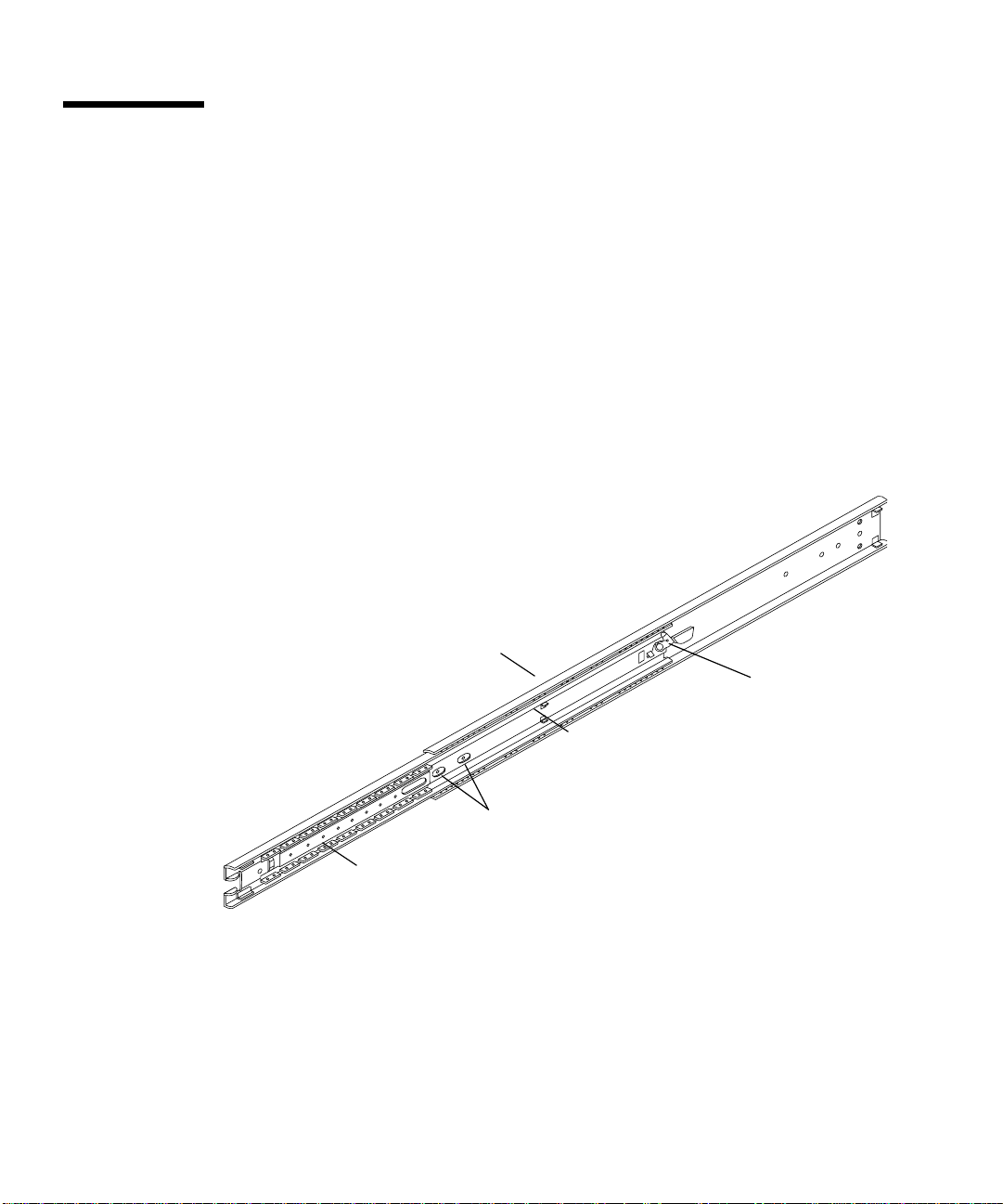
1. Attach a short mounting bracket to the front of each slide assembly. a. Extend the slide assembly to expose the holes for the front mounting bracket.
Release the coil spring catch on the inner rail to extend the slide assembly.
Slide assembly
Coil spring catch
Front
Holes for front mounting bracket
Runner
en-10 Sun Enterprise 220R Server Setup and Rackmounting Guide • December 1999
Inner rail
Page 15

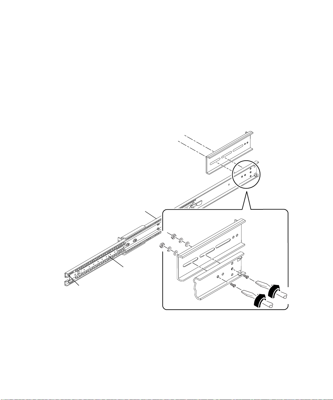
b. Position a short bracket over the front end of the slide assembly.
The lip of the bracket should face the front of the slide assembly, as shown.
c. Secure the short bracket to the slide assembly. Use two 8-32 panhead screws
with a flat washer, a lock washer, and a nut for each screw.
Slide assembly
Short bracket
Front
Chapter 2 Rack Installation en-11
Page 16

2. Attach a long mounting bracket to the rear end of each slide assembly. a. Position the long bracket over the rear end of the slide assembly.
Align the elongated slots at the end of the long bracket over the holes on the slide
assembly, as shown.
b. Secure the long bracket loosely to the slide assembly. Use two 8-32 panhead
screws, flat washers, lock washers, and nuts for each long bracket.
Do not tighten the screws completely. You may need to adjust the mounting
bracket when you install the slide assembly into the rack enclosure.
Long bracket
Rear
Slide assembly
Front
Runner
Inner rail
3. Push in the inner rail and runner on each slide assembly. a. Push the inner rail all the way into the slide assembly. If necessary, release the
coil spring catch.
b. Push in the runner until it stops.
en-12 Sun Enterprise 220R Server Setup and Rackmounting Guide • December 1999
Page 17

Install the Slide Assemblies Into the Rack Enclosure
1. Locate and mark the correct positions on the rack’s vertical mounting rails to
install the slide assemblies.
Allow four rack unit spaces (7.0 inches/17.78 cm) or 12 holes per server.
Because the holes on a standard rack enclosure are arranged in sets of 3 holes
spaced 5/8ths, 5/8ths, 4/8ths of an inch apart, determining which holes to use
for attaching a slide assembly depends on exactly where you locate the system.
You can either count the holes so that each slide assembly is installed at the same
height front-to-back and side-to-side in the rack, or use the Rack Buddy included
with your system documentation. Mark the location on the rack enclosure with a felt
tip marker or masking tape.
Install the slide assemblies into the lowest available position. If this is the first
system you are installing into the rack, use holes 3 and 4 or 5. Install additional
servers from the base up.
Rack Buddy
To use the Rack Buddy, complete these steps:
a. Place the Rack Buddy over the left front vertical rack rail. See the next figure.
b. Move the bottom of the Rack Buddy to the exact location on the rack rail where
the bottom of the system will be located.
c. Adjust the Rack Buddy so that the bottom server screw mounting location is
centered on the space in the Rack Buddy.
Chapter 2 Rack Installation en-13
Page 18

S
Rack rail
holes
d. Looking through the three holes on the Rack Buddy, locate the two rack rail
holes that are most visible through the Rack Buddy and mark them.
Use these two rack rail holes to attach the slide assembly to the rack rail. You will
only use two of the three holes to attach the slide assembly. The assembly bracket
has three holes to allow for the differences in spacing between the rack rail holes.
Mark the corresponding holes on the right front vertical rack rail.
erver
ounting
hole
en-14 Sun Enterprise 220R Server Setup and Rackmounting Guide • December 1999
Page 19

2. Attach one slide assembly to the right rack mounting rail, and the other slide
assembly to the left rack mounting rail. See the next figure.
a. With the help of an assistant, position the slide assembly on the inside of the
rack enclosure with the short mounting bracket facing the front of the rack.
Count the holes so that each slide assembly is installed at the same height
front-to-back and side-to-side in the rack or use the Rack Buddy as described
in Step 1.
b. Attach the front short mounting bracket of one slide assembly to the front rail
on the rack.
Secure the slide bracket assembly to the front mounting rail using two
Phillips 10-32 panhead screws. Use the holes marked in Step 1. Finger-tighten
the screws. Do not tighten the screws completely until all the screws are in
place and the slide assemblies are level.
c. Attach the long mounting bracket of the same slide assembly to the back rail of
the rack.
Secure the slide bracket assembly to the back mounting rail using two Phillips
10-32 panhead screws. Finger-tighten the screws. Do not tighten the screws
completely until all the screws are in place and the slide assemblies are level.
Chapter 2 Rack Installation en-15
Page 20

Note – You may need to slide the rear mounting bracket forward or backward on
the slide assembly to accommodate the depth of the rack.
3. Completely tighten all of the rackmounting screws. a. Make sure that the slide assemblies are level front-to-back and left-to-right. b. Tighten the eight 10-32 screws that secure the short and long mounting brackets
to the vertical rack rails.
c. Tighten the four 8-32 screws that secure the long mounting brackets to the slide
assemblies.
Tighten 10-32 screws
en-16 Sun Enterprise 220R Server Setup and Rackmounting Guide • December 1999
Tighten 8-32 screws
Page 21

Install the Server Into the Rack Enclosure
1. Verify that the runner on each slide assembly is pushed as far back as possible
into the slide assembly, as shown.
a. Push in the inner rail on each slide assembly until it reaches the stops that are
located furthest away from the front of the rack.
b. Push in the runner until it stops in the slide assembly.
Inner rail
Runner
Stops
Stops
Chapter 2 Rack Installation en-17
Page 22

2. Lift the server (one person on each side of the server) and approach the rack
enclosure with the back of the server facing the rack enclosure.
Caution – The system is heavy. Two people are required to move the system.
!
3. Align the crimped end of the inner glides on the server with the slide bracket
assemblies in the rack enclosure.
en-18 Sun Enterprise 220R Server Setup and Rackmounting Guide • December 1999
Page 23

4. Slide the server evenly into the rack enclosure until the inner glides stop in the slide.
5. On each side of the chassis, push in the flat spring catch on each inner glide and
push the server all the way into the rack.
Flat spring catch
Chapter 2 Rack Installation en-19
Page 24

6. Secure the chassis to the left and right vertical rails at the front of the rack.
Use a Phillips #2 screwdriver to tighten the four captive screws that secure the
system in the rack enclosure. These screws are in recessed access holes in the
decorative panels affixed to the system’s front panel, as shown.
Note – If you removed the side panels from the rack enclosure, leave them off until
after you complete the procedures in Chapter 3.
What Next
Go to Chapter 3 and complete the procedures for connecting the power cord and
cables to the back panel, powering on the system, and installing the operating
system.
en-20 Sun Enterprise 220R Server Setup and Rackmounting Guide • December 1999
Page 25

CHAPTER
3
System Setup
This chapter explains how to attach all the cords and cables needed to get the server
up and running. Where software is involved, this chapter explains some of what you
need to do, and points you to the appropriate software manuals for the rest of the
information.
To finish the setup procedure, complete the following tasks in the order listed:
■ “Connect the Power Cord” on page en-22
■ “Connect the Ethernet Cable” on page en-25
■ “Install Options” on page en-27
■ “Install a System Console” on page en-27
■ “Restore the Rack Enclosure” on page en-31
■ “Power On the System” on page en-31
■ “Install the Operating System” on page en-34
■ “Install Online Documentation” on page en-34
If you need to power off the system, see:
■ Sun Enterprise 220R Server Owner’s Guide
en-21
Page 26

Connect the Power Cord
1. Turn the front panel keyswitch to the Standby position.
en-22 Sun Enterprise 220R Server Setup and Rackmounting Guide • December 1999
Page 27

2. Connect the AC power cord to the right power inlet labeled 1 at the back of the system.
3. Connect the other end of the AC power cord to the power sequencer in the rack
enclosure or to an AC outlet.
See the instructions provided with your rack enclosure for information about the
power sequencer. The outlet must connect the system to a 15A circuit in North
America and Japan, and to a 10A circuit in Europe.
Note – If your server includes a second power supply, connect the second AC
power cord to the left power inlet labeled 2. You may connect the second power
supply to the same AC circuit as the first supply. However, for increased system
redundancy, you should connect the two power supplies to separate circuits.
Note – This system is suitable for use with IT Power Systems.
Chapter 3 System Setup en-23
Page 28

4. Tie-wrap the power cord(s) to the strain relief(s) on the back panel.
The Sun Enterprise 220R server is shipped with two strain reliefs attached to the
back panel. A strain relief is a plastic tie-wrap on a base that is inserted into the back
panel of the system. Use these reliefs to manage the power cords when you slide the
system in and out of the rack enclosure.
To tie-wrap a power cord, wrap the loose end of the tie-wrap around the cord and
insert it into the opening on the base of the strain relief. Pull the end to tighten the
tie-wrap.
To release the tie-wrap from the cord , press down the tab on the strain relief base
and loosen the tie wrap.
Strain reliefs
Tab
en-24 Sun Enterprise 220R Server Setup and Rackmounting Guide • December 1999
Page 29

Connect the Ethernet Cable
Connect only one Ethernet cable to the standard Ethernet port on the back of your
system—either a twisted-pair Ethernet (TPE) cable or a Media Independent Interface
(MII) transceiver. You can make additional Ethernet connections by installing PCI
Ethernet cards.
Sun Microsystems offers an MII-to-AUI transceiver as a separately orderable option.
A number of third-party MII transceivers are also available for connection to TX, T4,
FX, and AUI type Ethernet networks. See the Sun Enterprise 220R Server Owner’s
Guide for more information.
1. To connect a TPE cable: a. Connect the TPE cable to the RJ-45 connector on the system back panel. b. Connect the other end of the cable to the TPE outlet in the wall or the floor.
Chapter 3 System Setup en-25
Page 30

2. To connect an MII transceiver: a. Connect an MII transceiver to the MII Ethernet connector on the system back
panel.
b. Attach the network AUI cable to the AUI connector on the MII transceiver.
Lock the AUI connector.
Slide the latch to the right to lock the AUI cable to the MII-to-AUI transceiver. Use
a flat-blade screwdriver, if necessary.
c. Connect the other end of the MII transceiver to the appropriate network cable.
en-26 Sun Enterprise 220R Server Setup and Rackmounting Guide • December 1999
Page 31

Install Options
Many of the options ordered with your system may have been pre-installed at the
factory. For information about how to install other options, see the Sun Enterprise
220R Server Service Manual or contact your qualified Sun service provider. For
information about installing an additional internal disk drive, see the Sun Enterprise
220R Server Owner’s Guide.
Install a System Console
To install the server software, or to diagnose a problem, you need some way to enter
system commands and view system output. You can do one of the following:
■ Establish a tip connection from another Sun system.
■ Connect an ASCII terminal to serial port A.
■ Install a graphics card, monitor, and keyboard on your server. These components
are not shipped with the server.
How to Set Up a tip Connection
For information about establishing a tip connection, see the Sun Enterprise 220R
Server Owner’s Guide.
Chapter 3 System Setup en-27
Page 32

How to Connect an ASCII Terminal
1. Connect the terminal’s data cable to serial port A on the server ’s back panel.
2. Connect the terminal’s power cord to a grounded AC power outlet.
3. Set the terminal to receive:
■ At 9600 baud
■ An 8-bit signal with no parity and 1 stop bit
en-28 Sun Enterprise 220R Server Setup and Rackmounting Guide • December 1999
Page 33

How to Install a Graphics Console
To install a local graphics console you need a PCI-based graphics card, a monitor,
and a Sun-compatible keyboard, mouse, and mousepad. These components are not
shipped with your system. See the Sun Enterprise 220R Server Owner’s Guide for more
information.
1. Install the graphics card into a vacant PCI slot.
See the Sun Enterprise 220R Server Service Manual or contact your qualified Sun
service provider.
2. Attach the monitor’s video cable to the graphics card’s video port.
Tighten the thumbscrews to secure the connection.
3. Connect the monitor’s power cord to a grounded AC power outlet.
Chapter 3 System Setup en-29
Page 34

4. Connect the mouse to the keyboard.
5. Connect the keyboard to the system.
en-30 Sun Enterprise 220R Server Setup and Rackmounting Guide • December 1999
Page 35

Restore the Rack Enclosure
See the instructions provided with the rack enclosure to complete these steps.
1. Route and manage the cables within the rack cabinet.
2. Retract the enclosure’s anti-tip legs, if applicable.
3. Replace the side panels, if applicable.
4. Replace the front and back doors, if applicable.
Power On the System
Caution – Never move the system when the system power is on. Movement can
cause catastrophic disk drive failure. Always power off the system before moving it.
Caution – Before you power on the system, make sure that the cover is properly
installed.
1. Turn on power to any peripheral and external storage devices.
2. Turn on power to the monitor or terminal, if applicable.
Chapter 3 System Setup en-31
Page 36

3. Turn the front panel keyswitch to the Power-On/Off position.
4. Press the front panel Power button once.
en-32 Sun Enterprise 220R Server Setup and Rackmounting Guide • December 1999
Page 37

Note – The system may take anywhere from 30 seconds to two minutes before video
is displayed on the system monitor or the OK prompt appears on an attached
terminal. This time depends on the level of power-on self-test (POST) diagnostics
being performed.
Note – If you need to power off the system, see the Sun Enterprise 220R Server
Owner’s Guide for more information.
5. Turn the keyswitch to the Locked position.
The Locked position prevents accidentally powering-off the system.
Chapter 3 System Setup en-33
Page 38

Install the Operating System
If you are installing the Solaris 7 or later operating environment, refer to the
documentation accompanying your Solaris™ software and see the Sun Enterprise
220R Server Owner’s Guide for installation information.
If you are installing the Solaris 2.6 Hardware 5/98 operating environment , you
must use the Operating Environment Installation CD included with your system.
During the installation process, this CD installs certain software upgrade patches
that support Solaris releases running at the 450 MHz CPU speed.
This CD does not provide the content of the Solaris releases. You need to have the
Solaris media kit for the Solaris 2.6 Hardware 5/98 operating environment in order
to install the Solaris software itself. At the appropriate point in the installation
process, the Operating Environment Installation CD prompts you to install the Solaris
software.
This CD is not required if you are using the Solaris 7 or later operating environment.
For installation instructions, see the document included with Operating Environment
Installation CD.
Install Online Documentation
The documentation kit contains a CD-ROM disc with online documentation that
describes how to use, service, and maintain your system. Refer to the documents
supplied with the CD-ROM disc for installation instructions.
en-34 Sun Enterprise 220R Server Setup and Rackmounting Guide • December 1999
Page 39

APPENDIX
A
Rack Enclosure Requirements
The server is designed so that you can install it into a Sun 72-inch (184-cm) tall
Sun expansion cabinet or other EIA-compliant industry-standard rack enclosure
that meets the requirements listed in the table below. You need a Sun
rackmounting kit for each server that you will rackmount.
Rack Enclosure Feature Requirement
Load Bearing Capacity The rack must firmly support the weight of a Sun Enterprise 220R
server (75 lbs, 34 kg), plus the weight of the rackmounting
hardware, plus the weight of any other installed devices.
Vertical Space
Requirements
Airflow The system requires 113 cfm at 40
Each server requires four rack units (7 inches, 17.78 cm) of
vertical space for rack installation. A 72-inch (183-cm) cabinet
can hold up to nine servers.
o
C and 10,000 feet.
This air-flow rate corresponds to 328 lb/hr at any
altitude and to 78 cfm at 40
o
C and sea level.
For proper ventilation, each system in the rack enclosure requires
28 square inches (181 square cm) of unrestricted airflow into the
front of the system, and 23 square inches (148 square cm) of
unrestricted exhaust port at the back of the system. Maintain a
minimum 1.5 inches (3.8 cm) clearance between the system and
any front or back doors.
en-35
Page 40

Rack Enclosure Feature Requirement
Vertical Mounting Rail
Requirements
The rack must have two pairs of vertical mounting rails (one pair
in front, one in back) that conform to the EIA (RETMA) standard
for mounting hole spacing.
Left-side-to-right-side rail spacing (mounting hole center to
mounting hole center) for front and rear rails must be 18.3 inches
(46.5 cm).
Front-to-rear rail spacing must be at least 26.875 inches (68.26 cm)
and not more than 34.875 inches (88.5 cm) from the outside face of
the front rail to the outside face of the rear rail.
Front and rear vertical rail mounting faces must be parallel to
each other and to the front plane of the rack.
Doors and Panels If you are using a Sun expansion cabinet, you can remove the
front door and the side panels to increase access to the system.
Otherwise, see the instructions provided with the rack enclosure.
EMI Requirements Electromagnetic interference (EMI) shielding requirements are
met by the system chassis and metal side panels, which remain in
place when the unit is rack mounted.
Anti-Tilt Protection The rack must be bolted securely to the floor or equipped with a
sturdy and extendable anti-tip leg. You must prevent the cabinet
from tilting forward when one or more systems or devices are
fully extended out the front of the rack.
Minimum Service
Access
An area not less than 3 feet (1 meter) deep and 6 feet (2
meters) wide must be available in front of the rack for
installation and service access.
When fully extended on its mounting rail slides, the system will
protrude 29.75 inches (75.6 cm) forward of the rack’s front vertical
mounting rails.
Fire Containment The rack enclosure must meet Underwriters Laboratories, Inc. and
TUV Rheinland of N.A. requirements for fire containment.
en-36 Sun Enterprise 220R Setup and Rackmounting Guide • December 1999
Page 41

CHAPITRE
1
Guide d’installation et de montage en armoire
Ce guide explique comment installer le serveur de groupe de travail Sun Enterprise™
220R dans une armoire d'extension Sun ou toute autre armoire conforme EIA.
Ce guide examine les tâches et les sujets d'information suivants :
■ Mise en route — page fr-2 :
■ Déballage du système — page fr-2 ;
■ Vérification du contenu du kit — page fr-3 ;
■ Installation en armoire — page fr-7 :
■ Outils requis — page fr-7 ;
■ Mesures de sécurité — page fr-8 ;
■ Préparation de l'armoire — page fr-9
■ Fixation des supports aux groupes coulissants — page fr-10 ;
■ Installation des groupes coulissants dans l'armoire — page fr-13 ;
■ Installation du serveur dans l'armoire — page fr-17 ;
■ Installation du système — page fr-21 :
■ Branchement du cordon d'alimentation — page fr-22 ;
■ Connexion du câble Ethernet — page fr-25;
■ Installation des options — page fr-27 ;
■ Installation d'une console système — page fr-27 ;
■ Remise en place de l'armoire — page fr-31 ;
■ Mise sous tension du système — page fr-31 ;
■ Installation du système d’exploitation — page fr-34 ;
■ Installation de la documentation en ligne — page fr-34 ;
■ Caractéristiques de l'armoire — page fr-35.
fr-1
Page 42

Mise en route
Pour installer un serveur Sun Enterprise, effectuez les tâches suivantes dans l'ordre
indiqué :
■ Déballez le système et vérifiez le contenu du kit. Voir Chapitre 1.
■ Montez le serveur dans l'armoire. Voir Chapitre 2.
■ Configurez le serveur, mettez-le sous tension et installez le système d'exploitation.
Voir Chapitre 3.
Déballage du système
Votre système sort de l'usine avec la plupart des options internes requises installées.
Les périphériques qui ne sont pas installés en usine sont livrés séparément.
Les instructions de déballage figurent à l'extérieur du carton d'emballage.
Inspectez toutes les boîtes d’emballage afin de déceler tout signe de dommage
physique. Si une boîte d’emballage est abîmée, demandez à ce que l'agent du
transporteur soit présent lors de l'ouverture de cette boîte. Conservez l'ensemble
du contenu et du matériel d’emballage pour l'inspection de l'agent.
Contrôlez que vous avez bien reçu toutes les pièces commandées. Contactez
Sun Microsystems ou votre distributeur/revendeur s'il manque quelque chose.
fr-2 Guide d’installation et de montage en amoire du serveur Sun Enterprise 220R • décembre 1999
Page 43

Vérification du contenu du kit
Le carton d’emballage contient les pièces suivantes :
■ Serveur de groupe de travail Sun Enterprise 220R ;
■ Boîte d'accessoires.
Boîte d’accessoires
Serveur Sun Enterprise 220R
Chapitre 1 Guide d’installation et de montage en armoire fr-3
Page 44

Contenu de la boîte d’accessoires
La boîte d’accessoires contient les pièces suivantes :
Supports de
montage courts (2)
Supports de montage longs (2)
Matériel varié
Groupes coulissants (2)
Cordon(s) d’alimentation
Clé
Documentation client
Bracelet de soutien
Gabarit
fr-4 Guide d’installation et de montage en amoire du serveur Sun Enterprise 220R • décembre 1999
Page 45

La boîte d’accessoires contient également un sachet plastique de menu matériel : vis,
écrous et rondelles (illustration grandeur nature). Vous aurez besoin de ce matériel
pour installer les supports de montage en armoire et les groupes coulissants.
10-32 x 3/4
vis (8)
8-32 x 3/8
vis (8)
rondelle
plate (8)
rondelle
de blocage (8)
écrou (8)
Remarque – Des écrous à barre sont requis (mais ne sont pas fournis) pour les
armoires non-taraudées. Pour plus d'informations, consultez les instructions de
votre armoire. Les écrous à barre ne sont pas utilisés dans les armoires Sun.
Chapitre 1 Guide d’installation et de montage en armoire fr-5
Page 46

fr-6 Guide d’installation et de montage en amoire du serveur Sun Enterprise 220R • décembre 1999
Page 47

CHAPITRE
2
Installation en armoire
Ce chapitre fournit des instructions détaillées pour le montage en armoire du
serveur dans une armoire d'extension Sun ou toute autre armoire conforme EIA.
Pour installer un serveur Sun Enterprise 220R dans une armoire, complétez les
tâches suivantes dans l'ordre indiqué :
■ “Préparation de l'armoire”, page fr-9 ;
■ “Fixation des supports aux groupes coulissants”, page fr-10 ;
■ “Installation des groupes coulissants dans l'armoire”, page fr-13 ;
■ “Installation du serveur dans l'armoire”, page fr-17.
La Vue d'ensemble du montage en armoire - Sun Enterprise 220R Server qui figure dans la
documentation illustre les étapes du montage en armoire sous une forme graphique
très pratique. Ce chapitre fournit des informations détaillées sur les différentes
étapes.
Outils requis
■ Tournevis cruciforme n˚2 ;
■ Tournevis à lame plate ;
■ Jeu de clés Allen pour retirer les panneaux latéraux de certaines armoires ;
■ Une clé à molette pour serrer les écrous sur les supports de montage.
fr-7
Page 48

Avant de commencer
■ Déballez le système et vérifiez le contenu de l'emballage.
Reportez-vous au chapitre 1 pour les instructions.
■ Déballez la boîte des accessoires et placez les groupes coulissants, les supports de
montage et le reste du matériel sur une surface libre.
■ Vérifiez que vous disposez bien de tous les composants et de l'ensemble du
matériel illustrés dans “Contenu de la boîte d’accessoires”, page fr-4.
■ Examinez les caractéristiques que doit présenter l'armoire dans l'Annexe A de ce
guide.
■ Lisez les mesures de sécurité qui suivent.
Mesures de sécurité
Pour une description complète des mesures de sécurité à suivre lors de l'installation
d'un serveur Sun Enterprise 220R, reportez-vous au Guide du propriétaire du serveur
Sun Enterprise 220R.
Attention – Installez le système aussi bas que possible dans l'armoire. Pour une
!
meilleure stabilité, n'installez pas le système au-dessus d'équipements moins lourds
que le système lui-même.
Attention – Le système est lourd. Dans les procédures suivantes, deux personnes
!
fr-8 Guide d’installation et de montage en armoire du serveur Sun Enterprise 220R • décembre 1999
sont nécessaires pour le déplacer. Deux personnes sont également nécessaires pour
aligner et installer les groupes coulissants dans l'armoire.
Page 49

Attention – Pour une ventilation adéquate, il faut ménager pour chaque système
!
contenu dans l'armoire un espace de 181 cm
à l'avant du système et un espace de 148 cm
à l'arrière du système. Laissez un espace de 3,8 cm minimum (1,5 pouces) entre le
système et toute porte avant ou arrière. Pour plus d'informations, reportez-vous à
l’Annexe A.
2
(28 pouces carrés) pour l'entrée de l'air
2
(23 pouces carrés) pour la sortie de l'air
Préparation de l'armoire
1. Ouvrez et retirez (le cas échéant) les portes avant et arrière de l'armoire.
Consultez les instructions fournies avec votre armoire.
2. Stabilisez l'armoire en réglant ses pieds antibasculement ou en la boulonnant solidement au sol.
Consultez les instructions fournies avec votre armoire.
3. Retirez, le cas échéant, les panneaux latéraux de l'armoire.
Consultez les instructions fournies avec votre armoire. Retirer les panneaux latéraux
peut faciliter l'accès aux écrous et vis qui sont installés lors de la fixation du système
dans l'armoire.
Chapitre 2 Installation en armoire fr-9
Page 50
Fixation des supports aux groupes coulissants
Fixez deux supports de montage, un court et un long, à l'extérieur de chaque groupe
coulissant.
Répétez ces opérations pour chaque groupe coulissant.
1. Fixez un support de montage court à l'avant de chaque groupe coulissant. a. Etendez le groupe coulissant pour dégager les trous pour le support de
montage avant.
Relâchez le dispositif à ressort hélicoïdal placé sur le rail interne pour étirer le
groupe coulissant.
Groupe coulissant
Dispositif à ressort hélicoïdal
Avant
Trous pour le support de montage avant
Coulisseau
fr-10 Guide d’installation et de montage en armoire du serveur Sun Enterprise 220R • décembre 1999
Rail interne
Page 51

b. Placez un support de montage court sur l'extrémité avant du groupe coulissant.
Le rebord du support devrait se trouver face au devant du groupe coulissant,
comme indiqué.
c. Fixez le support court au groupe coulissant. Utilisez deux vis à tête ronde
8-32 avec une rondelle plate, une rondelle de blocage et un écrou pour chaque vis.
Groupe coulissant
Support cour t
Avant
Chapitre 2 Installation en armoire fr-11
Page 52

2. Fixez un support de montage long à l'extrémité arrière de chaque groupe coulissant. a. Placez le support long sur l'extrémité arrière du groupe coulissant.
Faites correspondre les orifices allongés qui se trouvent à l'extrémité du support
long avec les trous du groupe coulissant, comme indiqué.
b. Fixez sans serrer le support long au groupe coulissant. Utilisez deux vis à tête
ronde 8-32, rondelles plates, rondelles de blocage et écrous, pour chaque
support long.
Ne serrez pas les vis à fond. Il est possible que vous deviez ajuster le support de
montage lors de l'installation du groupe coulissant dans l'armoire.
Support long
Arrière
Groupe coulissant
Avant
Coulisseau
Rail interne
3. Faites rentrer le rail interne et le coulisseau sur chaque groupe coulissant. a. Faites rentrer complètement le rail interne dans le groupe coulissant.
Si nécessaire, relâchez le dispositif à ressort hélicoïdal.
b. Faites rentrer le coulisseau jusqu'à ce qu'il s'arrête.
fr-12 Guide d’installation et de montage en armoire du serveur Sun Enterprise 220R • décembre 1999
Page 53

Installation des groupes coulissants dans l'armoire
1. Repérez et marquez les positions exactes sur les rails de montage verticaux de
l'armoire pour l'installation des groupes coulissants.
Vous avez besoin de quatre espaces de une unité rack (4U, soit 17,78 cm ou 7,0
pouces) ou 12 trous par serveur. Etant donné que sur les armoires standards,
les trous sont regroupés par trois et espacés de 5/8e, 5/8e, 4/8e de pouce,
la détermination des trous à utiliser pour la fixation d'un groupe coulissant
dépend de la position exacte choisie pour le système.
Vous pouvez soit compter les trous de sorte que les groupes coulissants soient
installés à la même hauteur dans l'armoire, soit utiliser le gabarit inclus dans la
documentation de votre système. Marquez l'emplacement dans l'armoire avec un
feutre ou du ruban adhésif.
Installez les groupes coulissants à la plus basse des positions disponibles.
S'il s'agit du premier système que vous installez dans l'armoire, utilisez les trous 3 et
4 ou 5. Installez les autres serveurs en commençant par le bas.
Gabarit
Pour utiliser le gabarit, procédez comme suit :
a. Placez le gabarit sur le rail vertical avant gauche de l'armoire.
Consultez la figure ci-après.
b. Placez le bas du gabarit sur l'emplacement exact du rail de l'armoire où se
trouvera le bas du système.
c. Ajustez le gabarit de sorte que l'emplacement de montage de la vis inférieure
du serveur se trouve au centre du trou pratiqué dans le gabarit.
Chapitre 2 Installation en armoire fr-13
Page 54

d. En regardant à travers les trois trous du gabarit, repérez les deux trous du rail
T
de l'armoire les plus visibles et marquez-les.
Utilisez ces deux trous pour fixer le groupe coulissant au rail de l'armoire.
Vous n'utiliserez que deux des trois trous pour fixer le groupe coulissant.
Le support de montage est doté de trois trous afin de pouvoir s'adapter aux
différences d'espacement entre les trous des rails de l'armoire. Marquez les trous
correspondants sur le rail vertical avant droit de l'armoire.
rous des
rails de
l’armoire
rou de
montage
u serveur
fr-14 Guide d’installation et de montage en armoire du serveur Sun Enterprise 220R • décembre 1999
Page 55

2. Fixez un groupe coulissant au rail de montage droit de l'armoire et l'autre groupe
coulissant au rail de montage gauche. Consultez la figure ci-après.
a. En vous faisant aider d'une autre personne, placez le groupe coulissant à l'intérieur
de l'armoire avec le support de montage court face à l'avant de l'armoire.
Comptez les trous de sorte que les deux groupes coulissants soient installés à
la même hauteur (par rapport à l'avant et l'arrière de l'armoire et par rapport à
ses côtés) dans l'armoire ou utilisez le gabarit comme décrit à l'Etape 1.
b. Fixez le support de montage court avant de l'un des groupes
coulissants au rail avant de l'armoire.
Fixez le groupe coulissant au rail de montage avant en utilisant deux vis à
tête ronde 10-32 cruciformes. Utilisez les trous que vous avez marqués à
l'Etape 1. Serrez les vis manuellement. Ne serrez pas les vis complètement
avant de les avoir toutes installées et d'avoir vérifié que les groupes
coulissants sont de niveau.
c. Fixez le support de montage long du groupe coulissant au rail arrière de l'armoire.
Fixez le groupe coulissant au rail de montage arrière en utilisant deux vis à tête
ronde cruciformes 10-32. Serrez les vis manuellement. Ne serrez pas les vis
complètement avant de les avoir toutes installées et d'avoir vérifié que les
groupes coulissants sont de niveau.
Chapitre 2 Installation en armoire fr-15
Page 56

Remarque – Selon la profondeur de l'armoire, il se peut que vous deviez faire
coulisser le support de montage arrière vers l'avant ou l'arrière sur le groupe coulissant.
3. Serrez à fond toutes les vis utilisées pour le montage. a. Assurez-vous que les groupes coulissants sont de niveau (d'avant en arrière et
de gauche à droite).
b. Serrez les huit vis 10-32 qui fixent les supports de montage courts et longs aux
rails verticaux de l'armoire.
c. Serrez les quatre vis 8-32 qui fixent les supports de montage longs aux groupes
coulissants.
Serrez les vis 8-32
Serrez les vis 10-32
fr-16 Guide d’installation et de montage en armoire du serveur Sun Enterprise 220R • décembre 1999
Page 57

Installation du serveur dans l'armoire
1. Vérifiez que le coulisseau de chaque groupe coulissant est bien repoussé aussi
loin que possible dans le groupe coulissant, comme indiqué.
a. Enfoncez le rail interne de chaque groupe coulissant jusqu'à ce qu'il atteigne
les butées les plus éloignées par rapport à l'avant de l'armoire.
b. Enfoncez le coulisseau jusqu'à ce qu'il s’arrête dans le groupe coulissant.
Rail interne
Coulisseau
Butées
Butées
Chapitre 2 Installation en armoire fr-17
Page 58

2. Soulevez le serveur (une personne sur chaque côté) et rapprochez-vous de
l'armoire avec l'arrière du serveur côté armoire.
Attention – Le système est lourd. Deux personnes sont nécessaires pour le déplacer.
!
3. Alignez l'extrémité cannelée des coulisses intérieures du serveur avec les groupes
coulissants situés dans l'armoire.
fr-18 Guide d’installation et de montage en armoire du serveur Sun Enterprise 220R • décembre 1999
Page 59

4. Faites glisser le serveur à l'intérieur de l'armoire jusqu'à ce que le mouvement soit arrêté.
5. Sur chaque côté du châssis, poussez le dispositif à ressort plat de chaque coulisse
et enfoncez complètement le serveur dans l'armoire.
Dispositif à ressort plat
Chapitre 2 Installation en armoire fr-19
Page 60

6. Fixez le châssis aux rails verticaux droit et gauche à l'avant de l'armoire.
Utilisez un tournevis cruciforme n˚2 pour serrer les quatre vis prisonnières qui fixent
le système dans l’armoire. Ces vis se trouvent dans les renfoncements des panneaux
décoratifs qui sont fixés au panneau avant du système, comme indiqué.
Remarque – Si vous avez retiré les panneaux latéraux de l'armoire, ne les remettez
pas tant que vous n'avez pas terminé les opérations décrites dans le chapitre 3.
Et ensuite
Allez au chapitre 3 et effectuez les opérations de connexion du cordon
d'alimentation et des câbles au panneau arrière, de mise sous tension du système et
d'installation du système d'exploitation.
fr-20 Guide d’installation et de montage en armoire du serveur Sun Enterprise 220R • décembre 1999
Page 61

CHAPITRE
3
Installation du système
Ce chapitre explique comment raccorder l'ensemble des cordons et des câbles
nécessaires au fonctionnement du serveur. Lorsque le logiciel est concerné, ce
chapitre explique en partie ce que vous devez faire et indique, le cas échéant,
les manuels auxquels vous pouvez vous reporter pour le reste des informations.
Vous devez effectuer les tâches suivantes pour terminer l'installation de votre
système :
■ “Branchement du cordon d'alimentation”, page fr-22 ;
■ “Connexion du câble Ethernet”, page fr-25 ;
■ “Installation des options”, page fr-27 ;
■ “Installation d'une console système”, page fr-27 ;
■ “Remise en place de l'armoire”, page fr-31 ;
■ “Mise sous tension du système”, page fr-31 ;
■ “Installation du système d’exploitation”, page fr-34 ;
■ “Installation de la documentation en ligne”, page fr-34.
Si vous devez mettre votre système hors tension, reportez-vous au :
■ Guide du propriétaire du serveur Sun Enterprise 220R.
fr-21
Page 62

Branchement du cordon d'alimentation
1. Tournez l'interrupteur à clé du panneau avant pour le mettre en position Standby (Veille).
fr-22 Guide d’installation et de montage en armoire du serveur Sun Enterprise 220R • décembre 1999
Page 63

2. Branchez le cordon d'alimentation CA à la prise de droite (marquée du chiffre 1)
à l'arrière du système.
3. Branchez l'autre extrémité du cordon d'alimentation CA au séquenceur
d'alimentation de l'armoire ou à une prise CA.
Reportez-vous aux instructions fournies avec votre armoire pour toute information
sur le séquenceur d'alimentation. La prise doit connecter le système à un circuit 15A
en Amérique du nord et au Japon, à un circuit 10A en Europe.
Remarque – Si votre serveur est équipé d'une seconde alimentation, branchez le
second cordon d'alimentation CA à la prise de gauche (marquée 2). Vous pouvez
connecter la seconde alimentation au même circuit CA que la première. Cependant,
afin d'augmenter la redondance du système, nous vous conseillons de connecter les
deux alimentations à des circuits séparés.
Remarque – Ce système est adapté à une utilisation avec des alimentations IT.
Chapitre 3 Installation du système fr-23
Page 64

4. Fixez à l'aide d'une attache en caoutchouc le ou les cordons d'alimentation aux
détendeurs du panneau arrière.
Le serveur Sun Enterprise 220R est livré avec deux détendeurs sur le panneau
arrière. Un détendeur est une attache en plastique fixée à une base et insérée dans le
panneau arrière du système. Utilisez les détendeurs afin de retenir les cordons
d'alimentation lorsque vous ferez glisser le système dans, ou hors de, l'armoire.
Pour fixer un cordon d'alimentation à l'aide de l'attache, enroulez l'extrémité libre
de l'attache autour du cordon et insérez-la dans l'ouverture qui se trouve sur la base
du détendeur. Tirez sur l'attache pour la serrer.
Pour retirer l'attache du cordon, appuyez sur le taquet qui se trouve sur la base du
détendeur et desserrez l'attache.
Détendeurs
Taquet
fr-24 Guide d’installation et de montage en armoire du serveur Sun Enterprise 220R • décembre 1999
Page 65

Connexion du câble Ethernet
Ne connectez qu’un seul câble Ethernet au port standard Ethernet situé à l’arrière de
votre système — au choix, un câble de type paire torsadée Ethernet (TPE) ou un
câble d’émetteur-récepteur MII (Media Independent Interface). Vous pouvez établir
d’autres connexions Ethernet en installant des cartes Ethernet PCI.
Sun Microsystems propose sous la forme d’une option à commander séparément un
câble d’émetteur-récepteur MII vers AUI. Il existe de nombreux câbles MII similaires
d’autres marques qui permettent d’établir des connexions avec des réseaux Ethernet
de type TX, T4, FX et AUI. Pour plus d’informations, reportez-vous au Guide du
propriétaire du serveur Sun Enterprise 220R.
1. Pour connecter un câble TPE :
a. Connectez le câble TPE au connecteur RJ-45 situé sur le panneau arrière du
système.
b. Connectez l'autre extrémité du câble à la prise TPE murale ou au sol.
Chapitre 3 Installation du système fr-25
Page 66

2. Pour connecter un câble d’émetteur-récepteur MII :
a. Connectez un câble MII au connecteur Ethernet MII situé sur le panneau
arrière du système.
b. Raccordez le câble AUI du réseau au connecteur AUI situé sur le câble MII.
Verrouillez le connecteur AUI.
Faites glisser le loquet vers la droite pour verrouiller le câble AUI au câble
d’émetteur-récepteur MII vers AUI. Utilisez, si besoin est, un tournevis à lame plate.
c. Connectez l’autre extrémité du câble MII au câble réseau approprié.
fr-26 Guide d’installation et de montage en armoire du serveur Sun Enterprise 220R • décembre 1999
Page 67

Installation des options
La plupart des options commandées avec votre système ont été pré-installées en
usine. Pour plus d'informations sur l’installation d'autres options, consultez le Sun
Enterprise 220R Server Service Manual ou contactez votre représentant agréé Sun.
Pour plus d'informations sur l'ajout d'un lecteur de disque interne supplémentaire,
consultez le Guide du propriétaire du serveur Sun Enterprise 220R.
Installation d'une console système
Pour installer le logiciel serveur ou pour diagnostiquer un problème, vous devez
pouvoir d'une manière ou d'une autre entrer des commandes système et en
visualiser les résultats. Vous pouvez au choix :
■ Etablir une connexion tip depuis un autre système Sun.
■ Connecter un terminal ASCII au port série A.
■ Installer une carte graphique, un moniteur et un clavier sur votre serveur.
Ces composants ne sont pas fournis avec le serveur.
Comment établir une connexion tip
Pour plus d'informations sur l'établissement d'une connexion tip, reportez-vous au
Guide du propriétaire du serveur Sun Enterprise 220R.
Chapitre 3 Installation du système fr-27
Page 68

Comment connecter un terminal ASCII
1. Connectez le câble de données du terminal au port série A situé sur le panneau
arrière du serveur.
2. Branchez le cordon d'alimentation du terminal à une prise de terre CA.
3. Paramétrez le terminal pour recevoir :
■ à 9600 bauds ;
■ un signal 8 bits sans parité et 1 bit d'arrêt.
fr-28 Guide d’installation et de montage en armoire du serveur Sun Enterprise 220R • décembre 1999
Page 69

Comment installer une console graphique
Pour installer une console graphique locale, vous avez besoin d'une carte graphique
PCI, d'un moniteur, d'un clavier compatible Sun, d'une souris et d'un tapis de souris.
Ces composants ne sont pas fournis avec le système. Pour plus d'informations,
reportez-vous au Guide du propriétaire du serveur Sun Enterprise 220R.
1. Installez la carte graphique dans un emplacement PCI libre.
Consultez le Sun Enterprise 220R Server Service Manual ou contactez votre
représentant agréé Sun.
2. Raccordez le câble vidéo du moniteur au port vidéo de la carte graphique.
Serrez les vis à oreilles pour sécuriser la connexion.
3. Branchez le cordon d'alimentation du moniteur à une prise de terre CA.
Chapitre 3 Installation du système fr-29
Page 70

4. Branchez la souris au clavier.
5. Branchez le clavier au système.
fr-30 Guide d’installation et de montage en armoire du serveur Sun Enterprise 220R • décembre 1999
Page 71

Remise en place de l'armoire
Consultez les instructions fournies avec votre armoire pour effectuer ces opérations.
1. Faites passer et arrangez les câbles à l'intérieur de l'armoire.
2. Rétractez, le cas échéant, les pieds antibasculement de l'armoire.
3. Remettez en place, le cas échéant, les panneaux latéraux.
4. Remettez en place, le cas échéant, les portes avant et arrière.
Mise sous tension du système
Attention – Ne déplacez jamais un système sous tension. Tout mouvement peut
causer des erreurs de disque catastrophiques. Mettez toujours le système hors
tension avant de le déplacer.
Attention – Avant de mettre le système sous tension, assurez-vous que le capot est
bien installé.
1. Mettez sous tension l'ensemble des périphériques et dispositifs de stockage externes.
2. Mettez sous tension, le cas échéant, le moniteur ou le terminal.
Chapitre 3 Installation du système fr-31
Page 72

3. Mettez l'interrupteur à clé du panneau avant en position Power-On/Off (Marche/Arrêt).
4. Appuyez une fois sur le bouton Power (Marche) du panneau avant.
fr-32 Guide d’installation et de montage en armoire du serveur Sun Enterprise 220R • décembre 1999
Page 73

Remarque – Un laps de temps de 30 secondes à 2 minutes s'écoule avant que
l'image n'apparaisse sur le moniteur du système ou que l'invite OK ne s'affiche sur le
terminal branché au serveur. La durée nécessaire dépend du niveau des diagnostics
d'auto-test à la mise sous tension (POST) effectués.
Remarque – Si vous devez mettre le système hors tension, consultez le Guide du
propriétaire du serveur Sun Enterprise 220R.
5. Mettez l'interrupteur à clé en position Locked (verrouillé).
La position Locked empêche toute mise hors tension accidentelle du système.
Chapitre 3 Installation du système fr-33
Page 74

Installation du système d’exploitation
Si vous installez l'environnement d’exploitation Solaris 7 ou une version
ultérieure de ce logiciel, consultez la documentation qui accompagne votre logiciel
Solaris™ ainsi que le Guide du propriétaire du serveur Sun Enterprise 220R pour en
savoir plus sur l'installation.
Si vous installez l'environnement d’exploitation Solaris 2.6 Hardware 5/98 , vous
devez utiliser le CD Operating Environment Installation fourni avec votre système.
Pendant le processus d'installation, ce CD installe certains patchs de mise à jour du
logiciel, pour le support des versions de Solaris qui s'exécutent à la vitesse d'UC de
450 MHz.
Ce CD ne fournit pas le contenu des versions de Solaris. Vous devez disposer du kit
média Solaris pour l'environnement d’exploitation Solaris 2.6 Hardware 5/98 pour
installer le logiciel Solaris proprement dit. A un certain stade du processus
d'installation, le CD Operating Environment Installation vous invite à installer le
logiciel Solaris.
Ce CD n'est pas nécessaire si vous utilisez l'environnement d’exploitation Solaris 7
ou une version ultérieure de celui-ci.
Pour les instructions d'installation, consultez la documentation fournie avec le CD
Operating Environment Installation.
Installationde la documentationen ligne
Ce kit de documentation contient un CD-ROM comportant la documentation en
ligne qui décrit comment utiliser et entretenir votre système. Consultez les
documents fournis avec ce CD-ROM pour les instructions d’installation.
fr-34 Guide d’installation et de montage en armoire du serveur Sun Enterprise 220R • décembre 1999
Page 75

ANNEXE
A
Caractéristiques de l'armoire
Ce serveur est conçu pour que vous puissiez l'installer dans une armoire
d'extension Sun de 184 cm (72 pouces) de haut ou dans toute autre armoire
standard conforme EIA qui présente les caractéristiques énoncées dans le tableau
ci-dessous. Vous avez besoin d'un kit de montage en armoire Sun pour chacun des
serveurs que vous montez dans une armoire.
Caractéristique Valeur requise
Capacité de charge L'armoire doit supporter sans risque le poids d'un serveur Sun
Enterprise 220R (34 kg, 75 livres), plus le poids du matériel de
montage, plus le poids de tout autre périphérique installé.
Espace vertical Chaque serveur a besoin de quatre unités rack (4U, soit 17,78 cm ou
7 pouces) d'espace en hauteur pour l'installation en armoire. Une
armoire de 183 cm (72 pouces) peut contenir jusqu'à neuf serveurs.
o
Ventilation Le système nécessite 53 l/s à 40
149 kg/h à n'importe quelle altitude et à 36 ls/s à 40
de la mer.
C et 3000m. Ce taux correspond à
o
C au niveau
Pour une ventilation adéquate, il faut ménager pour chaque système
contenu dans l'armoire un espace de 181 cm
(28 pouces carrés) pour l'entrée de l'air à l'avant du système et un
espace de 148 cm
du système. Conservez un espace de 3,8 cm minimum (1,5 pouces)
entre le système et toute porte avant ou arrière.
3
(23 pouces carrés) pour la sortie de l'air à l'arrière
3
fr-35
Page 76

Caractéristique Valeur requise
Rails verticaux L'armoire doit être équipée de deux paires de rails de montage
verticaux (une paire à l'avant, une paire à l'arrière) conformes à la
norme EIA (RETMA) pour ce qui est de l'espacement des trous de
montage.
L'espacement entre les rails de gauche à droite (du centre des trous
de montage au centre des trous de montage) doit être de 46,5 cm
(18,3 pouces) pour les rails avant et les rails arrière.
L'espacement des rails de l'avant à l'arrière de l'armoire doit être
d'au moins 68,26 cm (26,875 pouces) et ne doit pas dépasser 88,5 cm
(34,875 pouces) mesuré de la face externe du rail avant à la face
externe du rail arrière.
Les faces de montage des rails verticaux avant et arrièredoivent être
parallèles entre elles et avec le plan avant de l'armoire.
Portes et panneaux Si vous utilisez une armoire d'extension Sun, vous pouvez retirer la
porte avant et les panneaux latéraux pour faciliter l'accès au
système. Sinon, reportez-vous aux instructions qui accompagnent
votre armoire.
Caractéristiques EMI Le châssis du système et les panneaux latéraux métalliques, qui
restent en place une fois l'unité montée dans l'armoire, doivent être
conformes aux normes de blindage contre les interférences
électromagnétiques (EMI).
Protection
antibasculement
L'armoire doit être solidement fixée au sol à l'aide de boulons ou
équipée d'un pied antibasculement réglable et robuste.
Vous devez empêcher que l'armoire ne bascule en avant lorsqu'un
ou plusieurs systèmes ou périphériques sont complètement sortis à
l'avant de l'armoire.
Accès minimum Une zone non-inférieure à 1 mètre (3 pieds) de profondeur et 2
mètres (6 pieds) de large doit être dégagée devant l'armoire pour
permettre l'accès lors des opérations d'installation et de
maintenance.
Lorsqu'il est complètement sorti sur ses rails, le système dépasse de
75,6 cm (29,75 pouces) des rails de montage verticaux avant de
l'armoire.
Résistance au feu L'armoire doit être conforme aux normes de résistance au feu de
l'Underwriters Laboratories, Inc. et du TUV Rheinland de N.A.
fr-36 Guide d’installation et de montage en armoire du serveur Sun Enterprise 220R • décembre 1999
Page 77

KAPITEL
1
Handbuch zu Installation und RackMontage
In diesem Handbuch wird erläutert, wie Sie den Sun Enterprise™ 220RArbeitsgruppenserver in ein Sun-Erweiterungsgehäuse oder ein anderes EIA-Rack
einbauen.
Die folgenden Arbeitsschritte und Themen werden in diesem Handbuch erläutert:
■ Vorbereitungen — Seite de-2
■ Auspacken des Systems — Seite de-2
■ Überprüfen des Inhalts der Lieferung — Seite de-3
■ Einbau in ein Rack — Seite de-7
■ Benötigtes Werkzeug — Seite de-7
■ Sicherheitsvorkehrungen — Seite de-8
■ Vorbereiten des Racks — Seite de-9
■ Anbringen der Montagewinkel an den Ausziehschienen — Seite de-10
■ Einbauen der Ausziehschienen in das Rack — Seite de-13
■ Einbauen des Servers in das Rack — Seite de-17
■ Installation des Systems — Seite de-21
■ Anschließen des Netzkabels — Seite de-22
■ Anschließen des Ethernet-Kabels — Seite de-25
■ Installieren von Optionen — Seite de-27
■ Installieren einer Systemkonsole — Seite de-27
■ Abschließen der Rack-Montage — Seite de-31
■ Einschalten des Systems — Seite de-31
■ Installieren des Betriebssystems — Seite de-34
■ Installieren der Online-Dokumentation — Seite de-34
■ Anforderungen an das Rack — Seite de-35
de-1
Page 78

Vorbereitungen
Zur Installation eines Sun Enterprise-Servers führen Sie die folgenden
Arbeitsschritte in der angegebenen Reihenfolge aus:
■ Packen Sie das System aus, und überprüfen Sie den Inhalt der Lieferung auf
Vollständigkeit. Siehe Kapitel 1.
■ Bauen Sie den Server in ein Rack ein. Siehe Kapitel 2.
■ Installieren Sie den Server, schalten Sie ihn ein, und installieren Sie das
Betriebssystem. Siehe Kapitel 3.
Auspacken des Systems
Bei der Lieferung ab Werk sind die meisten internen Optionen bereits im System
installiert. Nicht werkseitig installierte Peripheriegeräte werden getrennt geliefert.
Anweisungen zum Auspacken sind auf der Außenseite des Transportkartons
aufgedruckt.
Überprüfen Sie alle Transportkartons auf Anzeichen von Beschädigungen.
Wenn ein Transportkarton beschädigt ist, öffnen Sie den Karton nur in Anwesenheit
eines Vertreters des Transportunternehmens. Heben Sie den Inhalt und alle
Verpackungsmaterialien auf, damit Sie sie dem Vertreter des Transportunternehmens
gegebenenfalls vorlegen können.
Überprüfen Sie, ob alle bestellten Teile im Lieferumfang enthalten sind. Wenden Sie
sich an Sun Microsystems oder Ihren Sun-Vertriebsbeauftragten bzw. Ihren Händler,
wenn Teile fehlen.
de-2 Sun Enterprise 220R Server Handbuch zu Installation und Rack-Montage • Dezember 1999
Page 79

Überprüfen des Inhalts der Lieferung
Der Transportkarton enthält die folgenden Teile:
■ Sun Enterprise 220R-Arbeitsgruppenserver
■ Zubehörkarton
Zubehörkarton
Sun Enterprise 220R server
Kapitel 1 Handbuch zu Installation und Rack-Montage de-3
Page 80

Inhalt des Zubehörkartons
Der Zubehörkarton enthält die folgenden Teile:
Verschiedene Kleinteile
Kurze Montagewinkel (2)
Lange Montagewinkel (2)
Ausziehschienen (2)
Netzkabel
Schlüssel
Dokumentation
Erdungsarmband
Einbauhilfe
de-4 Sun Enterprise 220R Server Handbuch zu Installation und Rack-Montage • Dezember 1999
Page 81

Der Zubehörkarton enthält einen Beutel mit verschiedenen Kleinteilen: Schrauben,
Muttern und Unterlegscheiben (unten in tatsächlicher Größe abgebildet). Diese
Kleinteile benötigen Sie zum Einbau der Montagewinkel und der Ausziehschienen.
10-32 x 3/4
Schraube (8)
8-32 x 3/8
Schraube (8)
Flache
Unterlegs
scheibe (8)
Sicherungs
scheibe (8)
Mutter (8)
Hinweis – Für Racks mit Bohrungen ohne Gewinde benötigen Sie Stabmuttern
(nicht mitgeliefert). Nähere Informationen finden Sie in der Dokumentation zum
Rack. Bei Racks von Sun werden keine Stabmuttern verwendet.
Kapitel 1 Handbuch zu Installation und Rack-Montage de-5
Page 82

de-6 Sun Enterprise 220R Server Handbuch zu Installation und Rack-Montage • Dezember 1999
Page 83

KAPITEL
2
Einbau in ein Rack
In diesem Kapitel wird Schritt für Schritt erläutert, wie Sie den Server in ein SunErweiterungsgehäuse oder ein anderes EIA-Rack einbauen können.
Zum Einbau eines Sun Enterprise 220R-Servers in einem Rack führen Sie die
folgenden Arbeitsschritte in der angegebenen Reihenfolge aus:
■ „Vorbereiten des Racks“ auf Seite de-9
■ „Anbringen der Montagewinkel an den Ausziehschienen“ auf Seite de-10
■ „Einbauen der Ausziehschienen in das Rack” auf Seite de-13
■ „Einbauen des Servers in das Rack” auf Seite de-17
In Sun Enterprise 220R Server Übersicht über die Rack-Montage (als Teil der
Dokumentation geliefert) werden die beim Einbau in einem Rack auszuführenden
Arbeitsschritte anschaulich grafisch dargestellt. In diesem Kapitel sind die einzelnen
Schritte ausführlich erklärt.
Benötigtes Werkzeug
■ Kreuzschlitzschraubenzieher (Nr. 2)
■ Flachschraubenzieher
■ Satz von Innensechskantschlüsseln zum Abnehmen der Seitenverkleidungen bei
einigen Racks
■ Ein verstellbarer Schlüssel zum Anziehen der Muttern an den Montagewinkeln
de-7
Page 84

Vorbereitungen
■ Packen Sie das System aus, und überprüfen Sie den Inhalt der Lieferung auf
Vollständigkeit. Anweisungen finden Sie in Kapitel 1.
■ Packen Sie den Zubehörkarton aus, und legen Sie die Ausziehschienen, die
Montagewinkel und die Kleinteile auf einer übersichtlichen Fläche ab.
■ Überprüfen Sie, ob alle unter „Überprüfen des Inhalts der Lieferung” auf Seite
de-3 genannten Komponenten und Kleinteile vorhanden sind.
■ Lesen Sie die Anforderungen hinsichtlich des Racks, die in Anhang A dieses
Handbuchs aufgeführt sind.
■ Beachten Sie die folgenden Sicherheitsvorkehrungen.
Sicherheitsvorkehrungen
Eine vollständige Beschreibung der bei der Installation eines Sun Enterprise 220RServers zu beachtenden Sicherheitsvorkehrungen finden Sie im Sun Enterprise 220R-
Server Benutzerhandbuch.
Achtung – Installieren Sie das System so weit unten im Rack wie möglich.
!
Damit das Rack nicht instabil wird, dürfen Sie das System nicht über Geräten
installieren, die leichter sind als das System.
Achtung – Das System ist schwer. In den folgenden Arbeitsschritten sind zwei
!
de-8 Sun Enterprise 220R Server Handbuch zu Installation und Rack-Montage • Dezember 1999
Personen erforderlich, um das System zu bewegen. Auch für die Ausrichtung und
den Einbau der Ausziehschienen im Rack werden zwei Personen benötigt.
Page 85

Achtung – Um eine ausreichende Lüftung sicherzustellen, ist für jedes System im
!
Rack ein freier Lufteinlaßbereich von 181 cm
ein freier Luftauslaßbereich von 148 cm
Zwischen dem System und den Türen vorne und hinten (sofern vorhanden) muß ein
Abstand von mindestens 3,8 cm frei bleiben. Weitere Informationen finden Sie in
Anhang A.
2
an der Vorderseite des Systems und
2
an der Rückseite des Systems erforderlich.
Vorbereiten des Racks
1. Öffnen Sie am Rack die Türen vorne und hinten (sofern vorhanden), und nehmen Sie sie ab.
Siehe dazu die mit dem Rack gelieferten Anweisungen.
2. Stabilisieren Sie das Rack, indem Sie die Stabilisierungsständer ausklappen oder
das Rack fest am Boden verschrauben.
Siehe dazu die mit dem Rack gelieferten Anweisungen.
3. Nehmen Sie die Seitenverkleidungen des Racks (sofern vorhanden) ab.
Siehe dazu die mit dem Rack gelieferten Anweisungen. Wenn die
Seitenverkleidungen abgenommen werden, sind die Muttern und Schrauben, mit
denen Sie das System im Rack befestigen, möglicherweise besser zugänglich.
Kapitel 2 Einbau in ein Rack de-9
Page 86

Anbringen der Montagewinkel an den Ausziehschienen
Bringen Sie an den Ausziehschienen außen einen kurzen und einen langen
Montagewinkel an.
Führen Sie die folgenden Schritte für alle Ausziehschienen aus.
1. Bringen Sie einen kurzen Montagewinkel vorne an den Ausziehschienen an. a. Ziehen Sie die Ausziehschiene aus, damit die Bohrungen für den vorderen
Montagewinkel freiliegen.
Öffnen Sie den Schraubenfederverschluß an der Innenschiene, um die
Ausziehschiene auszuziehen.
Ausziehschiene
Schraubenfederverschluß
Vorne
Bohrungen für vorderen Montagewinkel
Laufschiene
de-10 Sun Enterprise 220R Server Handbuch zu Installation und Rack-Montage • Dezember 1999
Innenschiene
Page 87

b. Positionieren Sie den kurzen Montagewinkel über dem vorderen Ende der
Ausziehschiene.
Die Lasche am Montagewinkel muß wie abgebildet zum vorderen Ende der
Ausziehschiene weisen.
c. Befestigen Sie den kurzen Montagewinkel an der Ausziehschiene.
Verwenden Sie zwei 8-32-Flachkopfschrauben mit einer flachen
Unterlegscheibe, einer Sicherungsscheibe und einer Mutter für jede Schraube.
Ausziehschiene
Kurzer Winkel
Vorne
Kapitel 2 Einbau in ein Rack de-11
Page 88
2. Bringen Sie einen langen Montagewinkel hinten an den Ausziehschienen an. a. Positionieren Sie den langen Montagewinkel über dem hinteren Ende der
Ausziehschiene.
Richten Sie die langen schmalen Aussparungen am Ende des langen
Montagewinkels wie abgebildet an den Bohrungen in der Ausziehschiene aus.
b. Befestigen Sie den langen Montagewinkel locker an der Ausziehschiene.
Verwenden Sie zwei 8-32-Flachkopfschrauben, flache Unterlegscheiben,
Sicherungsscheiben und Muttern für jeden langen Montagewinkel.
Ziehen Sie die Schrauben nicht vollständig an. Beim Einbauen der Ausziehschiene
in das Rack müssen Sie die Montagewinkel möglicherweise noch verstellen.
Langer Winkel
Hinten
Ausziehschiene
Vorne
Laufschiene
Innenschiene
3. Schieben Sie die Innenschiene und die Laufschiene der Ausziehschienen wieder hinein.
a. Schieben Sie die Innenschiene vollständig in die Ausziehschiene hinein.
Öffnen Sie gegebenenfalls den Schraubenfederverschluß.
b. Schieben Sie die Laufschiene bis zum Anschlag hinein.
de-12 Sun Enterprise 220R Server Handbuch zu Installation und Rack-Montage • Dezember 1999
Page 89

Einbauen der Ausziehschienen in das Rack
1. Markieren Sie an den vertikalen Montagestreben des Racks die richtigen
Positionen für die Montage der Ausziehschienen.
Pro Server sind vier Rack-Einheiten (17,78 cm) bzw. 12 Bohrungen zu
veranschlagen. Die Bohrungen bei einem Standard-Rack sind in Gruppen zu je 3
Bohrungen im Abstand von 5/8, 5/8, 4/8 Zoll (ca. 1,59 bzw. 1,27 cm) angeordnet.
Welche Bohrungen für das Anbringen einer Ausziehschiene zu verwenden sind,
hängt daher davon ab, an welcher Stelle Sie das System einbauen wollen.
Sie können die Bohrungen abzählen, so daß alle Ausziehschienen vorne und hinten
sowie auf beiden Seiten auf derselben Höhe angebracht werden, oder Sie verwenden
die mit der Dokumentation zum System gelieferte Einbauhilfe. Markieren Sie die
Position am Rack mit einem Filzstift oder mit Klebeband.
Installieren Sie die Ausziehschienen in der niedrigstmöglichen Position.
Beim Einbauen des ersten Systems in das Rack verwenden Sie die Bohrungen 3 und
4 oder 5. Installieren Sie zusätzliche Server immer von unten nach oben.
Einbauhilfe
Bei Verwendung der Einbauhilfe führen Sie die folgenden Schritte aus:
a. Halten Sie die Einbauhilfe an die vordere linke vertikale Montagestrebe des
Racks. Siehe dazu die nächste Abbildung.
b. Halten Sie die Unterkante der Einbauhilfe genau an der Position an die
Montagestrebe, an der sich später die Unterseite des Systems befinden wird.
c. Halten Sie die Einbauhilfe so, daß sich die untere Montagebohrung für den
Server in der Mitte der Aussparung in der Einbauhilfe befindet.
Kapitel 2 Einbau in ein Rack de-13
Page 90

d. Schauen Sie durch die drei Bohrungen der Einbauhilfe, und markieren Sie die
zwei Bohrungen in der Montagestrebe des Racks, die durch die Einbauhilfe am
besten zu sehen sind.
Verwenden Sie diese beiden Bohrungen in der Montagestrebe des Racks zum
Anbringen der Ausziehschiene an der Montagestrebe. Zum Anbringen der
Ausziehschiene verwenden Sie nur zwei der drei Bohrungen. Der Montagewinkel
ist mit drei Bohrungen versehen, da die Bohrungen in der Montagestrebe in
unterschiedlichen Abständen angeordnet sind. Markieren Sie die entsprechenden
Bohrungen an der vorderen rechten vertikalen Montagestrebe des Racks.
Bohrungen in
den Montagestreben des
Racks
erver-
ontage-
ohrung
2. Bringen Sie eine Ausziehschiene an der rechten Montagestrebe des Racks und die
andere an der linken Montagestrebe des Racks an. Siehe dazu die nächste Abbildung.
de-14 Sun Enterprise 220R Server Handbuch zu Installation und Rack-Montage • Dezember 1999
Page 91

a. Lassen Sie sich von einer zweiten Person helfen, und halten Sie die
Ausziehschiene so an die Innenseite des Racks, daß der kurze Montagewinkel
zur Vorderseite des Racks weist.
Zählen Sie die Bohrungen ab, damit die Ausziehschienen vorne und hinten
sowie auf beiden Seiten auf gleicher Höhe angebracht werden, oder
verwenden Sie wie in Schritt 1 erläutert die Einbauhilfe.
b. Bringen Sie den vorderen, kurzen Montagewinkel einer
Ausziehschiene an der vorderen Montagestrebe des Racks an.
Befestigen Sie den an der Ausziehschiene angebrachten Montagewinkel mit
zwei 10-32-Kreuzschlitzflachkopfschrauben an der vorderen Montagestrebe.
Verwenden Sie die in Schritt 1 markierten Bohrungen. Ziehen Sie die Schrauben
von Hand an. Ziehen Sie die Schrauben erst dann vollständig an, wenn alle
Schrauben angebracht und die Ausziehschienen gerade ausgerichtet wurden.
c. Bringen Sie den langen Montagewinkel derselben Ausziehschiene an der
hinteren Montagestrebe des Rack an.
Befestigen Sie den an der Ausziehschiene angebrachten Montagewinkel mit
zwei 10-32-Kreuzschlitzflachkopfschrauben an der hinteren Montagestrebe.
Ziehen Sie die Schrauben von Hand an. Ziehen Sie die Schrauben erst dann
vollständig an, wenn alle Schrauben angebracht und die Ausziehschienen
gerade ausgerichtet wurden.
Kapitel 2 Einbau in ein Rack de-15
Page 92

Hinweis – Je nach Tiefe des Racks müssen Sie den hinteren Montagewinkel
eventuell nach vorne oder nach hinten versetzen.
3. Ziehen Sie alle Rack-Montageschrauben vollständig an. a. Vergewissern Sie sich, daß die Ausziehschienen vorne und hinten sowie auf
beiden Seiten auf derselben Höhe angebracht sind.
b. Ziehen Sie die acht 10-32-Schrauben an, mit denen die langen und kurzen
Montagewinkel an den vertikalen Montagestreben des Racks befestigt sind.
c. Ziehen Sie die vier 8-32-Schrauben an, mit denen die langen Montagewinkel
an den Ausziehschienen befestigt sind.
8-32-Schrauben anziehen
10-32-Schrauben anziehen
de-16 Sun Enterprise 220R Server Handbuch zu Installation und Rack-Montage • Dezember 1999
Page 93

Einbauen des Servers in das Rack
1. Stellen Sie sicher, daß die Laufschiene der einzelnen Ausziehschienen so weit wie
möglich in die Ausziehschiene hineingeschoben wird.
a. Drücken Sie die Innenschiene der Ausziehschiene bis zu den Anschlägen
hinein, die sich am weitesten von der Vorderseite des Racks entfernt befinden.
b. Drücken Sie die Laufschiene bis zum Anschlag in die Ausziehschiene hinein.
Innenschiene
Laufschiene
Anschläge
Anschläge
Kapitel 2 Einbau in ein Rack de-17
Page 94

2. Heben Sie den Server mit einer Person auf jeder Seite des Servers an, und tragen
Sie den Server so zum Rack, daß die Rückseite des Servers auf die Vorderseite des
Racks weist.
Achtung – Das System ist schwer. Zum Bewegen des Systems sind zwei Personen
!
erforderlich.
3. Richten Sie das gefaltete Ende der Gleitträger am Server an den Ausziehschienen im Rack aus.
de-18 Sun Enterprise 220R Server Handbuch zu Installation und Rack-Montage • Dezember 1999
Page 95

4. Schieben Sie den Server gleichmäßig in das Rack, bis sich der Gleitträger nicht
weiter in die Ausziehschiene hineinschieben läßt.
5. Drücken Sie auf beiden Seiten des Chassis den Flachfederverschluß an die
Gleitträger an, und schieben Sie den Server ganz in das Rack hinein.
Flachfederverschluß
Kapitel 2 Einbau in ein Rack de-19
Page 96

6. Befestigen Sie das Chassis links und rechts an den vertikalen vorderen Montagestreben des Racks.
Ziehen Sie mit einem Kreuzschlitzschraubenzieher Nr. 2 die vier unverlierbaren
Schrauben an, mit denen das System im Rack befestigt wird. Diese Schrauben sind
in tiefliegende Bohrungen in den Zierblenden eingelassen, die an der Vorderseite des
Systems befestigt sind (siehe Abbildung).
Hinweis – Wenn Sie die Seitenverkleidungen vom Rack abgenommen haben,
bringen Sie diese noch nicht wieder an. Dies tun Sie erst, nachdem Sie die in
Kapitel 3 erläuterten Arbeitsschritte ausgeführt haben.
Das weitere Vorgehen
Fahren Sie mit Kapitel 3 fort. Dort wird erläutert, wie Sie das Netzkabel und andere
Kabel an der Rückseite des Systems anschließen, das System einschalten und das
Betriebssystem installieren.
de-20 Sun Enterprise 220R Server Handbuch zu Installation und Rack-Montage • Dezember 1999
Page 97

KAPITEL
3
Installation des Systems
In diesem Kapitel wird beschrieben, wie Sie alle Kabel anschließen, die zum Betrieb
des Servers benötigt werden. Einige Schritte der Software-Installation werden in
diesem Kapitel erläutert. Darüber hinaus wird auf die Software-Handbücher
verwiesen, in denen Sie alle weiteren Informationen finden.
Führen Sie die folgenden Arbeitsschritte aus, um die Installation des Systems
abzuschließen:
■ „Anschließen des Netzkabels” auf Seite de-22
■ „Anschließen des Ethernet-Kabels” auf Seite de-25
■ „Installieren von Optionen” auf Seite de-27
■ „Installieren einer Systemkonsole” auf Seite de-27
■ „Abschließen der Rack-Montage” auf Seite de-31
■ „Einschalten des Systems” auf Seite de-31
■ „Installieren des Betriebssystems” auf Seite de-34
■ „Installieren der Online-Dokumentation” auf Seite de-34
Wenn Sie das System ausschalten müssen, schlagen Sie im folgenden Handbuch nach:
■ Sun Enterprise 220R-Server Benutzerhandbuch
de-21
Page 98

Anschließen des Netzkabels
1. Stellen Sie den Schlüsselschalter an der Vorderseite des Systems in die Position „Standby“.
de-22 Sun Enterprise 220R Server Handbuch zu Installation und Rack-Montage • Dezember 1999
Page 99

2. Schließen Sie das Netzkabel an die rechte, mit 1 gekennzeichnete Netzbuchse an
der Rückseite des Systems an.mon
3. Schließen Sie das andere Ende des Netzkabels an ein Stromverteilungsmodul im
Rack oder eine Netzsteckdose an.
Informationen zum Stromverteilungsmodul finden Sie in den mit dem Rack
gelieferten Anweisungen. Über die Netzsteckdose muß das System mit einem
15-A-Stromkreis (Nordamerika und Japan) bzw. einem 10-A-Stromkreis (Europa)
verbunden werden.
Hinweis – Wenn der Server mit einem zweiten Netzteil ausgestattet ist, schließen
Sie das zweite Netzkabel an die linke, mit 2 gekennzeichnete Netzbuchse an.
Sie können das zweite Netzteil an denselben Stromkreis wie das erste anschließen.
Eine höhere Systemredundanz ist jedoch gegeben, wenn Sie die beiden Netzteile an
unterschiedliche Stromkreise anschließen.
Hinweis – Das System kann mit IT Power Systems eingesetzt werden.
Kapitel 3 Installation des Systems de-23
Page 100

4. Befestigen Sie das/die Netzkabel an der/den Zugentlastungshalterung/en an der Rückseite.
Der Sun Enterprise 220R-Server wird mit zwei Zugentlastungshalterungen geliefert, die
an der Rückseite des Systems angebracht sind. Eine Zugentlastungshalterung ist ein
Kunststoffkabelbinder auf einem Sockel, der in die Rückseite des Systems eingesetzt ist.
Wenn Sie die Netzkabel an diesen Halterungen befestigen, lassen sie sich besser
handhaben, wenn Sie das System in das Rack schieben oder daraus hervorziehen.
Zum Befestigen des Netzkabels führen Sie das lose Ende des Kabelbinders um
das Kabel und dann in die Öffnung im Sockel der Zugentlastungshalterung ein.
Ziehen Sie den Kabelbinder am losen Ende fest an.
Zum Lösen des Netzkabels drücken Sie die Lasche am Sockel der
Zugentlastungshalterung nach unten und lösen den Kabelbinder.
Zugentlastungshalterungen
Lasche
de-24 Sun Enterprise 220R Server Handbuch zu Installation und Rack-Montage • Dezember 1999
 Loading...