

Page 1

Ultra™Enterprise™6000/5000/4000 SystemsManual
The Network Is the Computer
Sun Microsystems Computer Company
2550 Garcia Avenue
Mountain View, CA 94043 USA
415 960-1300 fax 415 969-9131
Part No.: 802-3845-11
Revision A, November 1996
™
Page 2
Copyright 1996 Sun Microsystems,Inc.2550GarciaAvenue,MountainView, California 94043-1100U.S.A.
All rights reserved.Thisproductordocumentisprotectedbycopyrightanddistributedunderlicensesrestrictingitsuse,copying,distribution,
and decompilation. No part of this productordocumentmaybereproducedinanyformbyanymeanswithoutpriorwrittenauthorizationof
Sun and its licensors, if any.
Portions of this productmaybederivedfromtheUNIX®system and fromtheBerkeley4.3BSDsystem,licensedfromtheUniversityof
California. UNIX is a registeredtrademarkintheUnitedStatesandinothercountriesandisexclusivelylicensedbyX/OpenCompanyLtd.
Third-partysoftware,includingfonttechnologyinthisproduct,isprotectedbycopyrightandlicensedfrom Sun’s suppliers.
RESTRICTED RIGHTS LEGEND: Use, duplication, or disclosurebytheU.S.GovernmentissubjecttorestrictionsofFAR52.227-14(g)(2)(6/87)
and FAR52.227-19(6/87),orDFAR252.227-7015(b)(6/95)andDFAR227.7202-3(a).
Sun, Sun Microsystems,theSunlogo,Solaris,Enterprise,Ultra,UltraComputing,UltraServer, and UltraSPARC aretrademarksorregistered
trademarks of Sun Microsystems,Inc.intheUnitedStatesandinothercountries.AllSPARCtrademarksareusedunderlicenseandare
trademarks or registeredtrademarksofSPARCInternational,Inc.intheUnitedStatesandinothercountries.ProductsbearingSPARC
trademarks arebaseduponanarchitecturedevelopedbySunMicrosystems,Inc.
The OPEN LOOK®and Sun™ Graphical User Interfaces weredevelopedbySunMicrosystems,Inc.foritsusersandlicensees.Sun
acknowledges thepioneeringeffortsofXeroxCorporationinresearchinganddevelopingtheconceptofvisualorgraphicaluserinterfacesforthe
computer industry.SunholdsanonexclusivelicensefromXeroxtotheXeroxGraphicalUserInterface,whichlicensealsocoversSun’slicensees
who implement OPEN LOOK GUIs and otherwise comply with Sun’s written license agreements.
THIS PUBLICATION IS PROVIDED “AS IS” WITHOUT WARRANTY OF ANY KIND, EITHER EXPRESS OR IMPLIED, INCLUDING,
BUT NOT LIMITED TO, THE IMPLIED WARRANTIES OF MERCHANTABILITY, FITNESS FOR A PARTICULAR PURPOSE, OR
NON-INFRINGEMENT.
Copyright 1996 Sun Microsystems,Inc.,2550GarciaAvenue,MountainView, Californie 94043-1100U.S.A.
Tous droitsréservés.Ceproduitoudocumentestprotégéparun copyright et distribué avec des licences qui en restreignentl’utilisation,lacopie
et ladécompilation.Aucunepartiedeceproduitoudesadocumentationassociéenepeutêtrereproduite sous aucune forme, par quelque moyen
que ce soit, sans l’autorisation préalable et écrite de Sun et de ses bailleurs de licence, s’il y en a.
Des parties de ce produitpourront être derivées du système UNIX®et du système Berkeley 4.3 BSD licencié par l’Université de Californie. UNIX
est une marque enregistrée aux Etats-Unis et dans d’autres pays, et licenciée exclusivement par X/Open Company Ltd. Le logiciel détenu par des
tiers, et qui comprendla technologie relative aux polices de caractères, est protégé par un copyright et licencié par des fournisseurs de Sun.
Sun, Sun Microsystems,le logo Sun, Solaris, Enterprise, Ultra, UltraComputing, UltraServer,et UltraSPARCsont des marques déposées ou
enregistréesde Sun Microsystems, Inc. aux Etats-Unis et dans d’autres pays. Toutesles marques SPARC, utilisées sous licence, sont des marques
déposées ou enregistréesde SPARCInternational, Inc. aux Etats-Unis et dans d’autres pays. Les produits portant les marques SPARC sont basés
sur une architecturedéveloppée par Sun Microsystems, Inc.
Les utilisateurs d’interfaces graphiques OPEN LOOK®et Sun™ ont été développés de Sun Microsystems, Inc. pour ses utilisateurs et licenciés.
Sun reconnaîtles efforts de pionniers de Xerox Corporation pour la rechercheet le développement du concept des interfaces d’utilisation visuelle
ou graphique pour l’industrie de l’informatique. Sun détient une licence non exclusive de Xerox sur l’interface d’utilisation graphique, cette
licence couvrant aussi les licenciés de Sun qui mettent en place les utilisateurs d’interfaces graphiques OPEN LOOK et qui en outre se
conforment aux licences écrites de Sun.
CETTE PUBLICATION EST FOURNIE "EN L’ETAT" SANS GARANTIE D’AUCUNE SORTE, NI EXPRESSE NI IMPLICITE, Y COMPRIS, ET
SANS QUE CETTE LISTE NE SOIT LIMITATIVE, DES GARANTIES CONCERNANT LA VALEUR MARCHANDE, L’APTITUDE DES
PRODUITS A REPONDRE A UNE UTILISATIONPARTICULIERE OU LE FAIT QU’ILS NE SOIENT PAS CONTREFAISANTS DE PRODUITS
DE TIERS.
Please
Recycle
Page 3

Contents
Preface. . . . . . . . . . . . . . . . . . . . . . . . . . . . . . . . . . . . . . . . . . . . . . . xxv
Part 1—Product Description
1. Product Overview . . . . . . . . . . . . . . . . . . . . . . . . . . . . . . . . . . . . . 1-1
1.1 Standard Features. . . . . . . . . . . . . . . . . . . . . . . . . . . . . . . . . 1-1
1.2 Basic Definitions. . . . . . . . . . . . . . . . . . . . . . . . . . . . . . . . . . 1-5
1.3 Internal Options . . . . . . . . . . . . . . . . . . . . . . . . . . . . . . . . . . 1-7
2. Safety Precautions and Tools Requirements . . . . . . . . . . . . . . 2-1
2.1 Safety Precautions . . . . . . . . . . . . . . . . . . . . . . . . . . . . . . . . 2-1
2.2 Symbols . . . . . . . . . . . . . . . . . . . . . . . . . . . . . . . . . . . . . . . . . 2-2
2.3 Tools Required . . . . . . . . . . . . . . . . . . . . . . . . . . . . . . . . . . . 2-4
Part 2—System Components
3. CPU/Memory Boards and Components . . . . . . . . . . . . . . . . . . 3-1
3.1 Handling Boards and Assemblies . . . . . . . . . . . . . . . . . . . 3-2
3.2 Filler Panels and Load Boards . . . . . . . . . . . . . . . . . . . . . . 3-3
3.3 Hot-Plug Feature . . . . . . . . . . . . . . . . . . . . . . . . . . . . . . . . . 3-4
iii
Page 4

3.4 CPU/Memory Boards . . . . . . . . . . . . . . . . . . . . . . . . . . . . . 3-5
3.4.1 Removing a Board. . . . . . . . . . . . . . . . . . . . . . . . . . . . 3-6
3.4.2 Installing a Board . . . . . . . . . . . . . . . . . . . . . . . . . . . . 3-9
3.4.3 UltraSPARC Modules. . . . . . . . . . . . . . . . . . . . . . . . . 3-14
3.4.4 Handling Precautions. . . . . . . . . . . . . . . . . . . . . . . . . 3-14
3.4.5 Memory Modules (SIMMs) . . . . . . . . . . . . . . . . . . . . 3-19
4. I/O Boards and Components. . . . . . . . . . . . . . . . . . . . . . . . . . . . 4-1
4.1 Handling Boards and Assemblies . . . . . . . . . . . . . . . . . . . 4-2
4.2 Filler Panels and Load Boards . . . . . . . . . . . . . . . . . . . . . . 4-3
4.3 SCSI Termination . . . . . . . . . . . . . . . . . . . . . . . . . . . . . . . . . 4-4
4.4 Hot-Plug Feature . . . . . . . . . . . . . . . . . . . . . . . . . . . . . . . . . 4-5
4.5 I/O Boards. . . . . . . . . . . . . . . . . . . . . . . . . . . . . . . . . . . . . . . 4-5
4.5.1 tpe-link-test? Variable . . . . . . . . . . . . . . . . . . . . 4-6
4.5.2 Removing a Board. . . . . . . . . . . . . . . . . . . . . . . . . . . . 4-11
4.5.3 Installing a Board . . . . . . . . . . . . . . . . . . . . . . . . . . . . 4-14
4.5.4 SBus Cards. . . . . . . . . . . . . . . . . . . . . . . . . . . . . . . . . . 4-19
4.5.5 Graphics (UPA) Cards . . . . . . . . . . . . . . . . . . . . . . . . 4-27
4.5.6 Fibre Cards. . . . . . . . . . . . . . . . . . . . . . . . . . . . . . . . . . 4-31
5. Disk Boards and Components . . . . . . . . . . . . . . . . . . . . . . . . . . 5-1
5.1 Handling Boards and Assemblies . . . . . . . . . . . . . . . . . . . 5-2
5.2 Filler Panels and Load Boards . . . . . . . . . . . . . . . . . . . . . . 5-2
5.3 SCSI Termination . . . . . . . . . . . . . . . . . . . . . . . . . . . . . . . . . 5-4
5.4 Hot-Plug Feature . . . . . . . . . . . . . . . . . . . . . . . . . . . . . . . . . 5-5
5.5 Disk Boards . . . . . . . . . . . . . . . . . . . . . . . . . . . . . . . . . . . . . . 5-5
iv Ultra Enterprise 6000/5000/4000 Systems Manual—November 1996
Page 5

5.5.1 Removing a Board. . . . . . . . . . . . . . . . . . . . . . . . . . . . 5-6
5.5.2 Installing a Board . . . . . . . . . . . . . . . . . . . . . . . . . . . . 5-8
5.5.3 Disk Drives . . . . . . . . . . . . . . . . . . . . . . . . . . . . . . . . . 5-13
6. Clock Board . . . . . . . . . . . . . . . . . . . . . . . . . . . . . . . . . . . . . . . . . . 6-1
6.1 Handling Boards and Assemblies . . . . . . . . . . . . . . . . . . . 6-2
6.2 Clock Board. . . . . . . . . . . . . . . . . . . . . . . . . . . . . . . . . . . . . . 6-2
6.2.1 ConsoleBus. . . . . . . . . . . . . . . . . . . . . . . . . . . . . . . . . . 6-4
6.2.2 Clocks . . . . . . . . . . . . . . . . . . . . . . . . . . . . . . . . . . . . . . 6-4
6.2.3 Reset logic . . . . . . . . . . . . . . . . . . . . . . . . . . . . . . . . . . 6-4
6.2.4 Removing a Clock Board . . . . . . . . . . . . . . . . . . . . . . 6-5
6.2.5 Installing a Clock Board. . . . . . . . . . . . . . . . . . . . . . . 6-6
7. Power Supplies . . . . . . . . . . . . . . . . . . . . . . . . . . . . . . . . . . . . . . . 7-1
7.1 Safety Precautions . . . . . . . . . . . . . . . . . . . . . . . . . . . . . . . . 7-2
7.2 Distribution. . . . . . . . . . . . . . . . . . . . . . . . . . . . . . . . . . . . . . 7-3
7.3 Peripheral Power Supply. . . . . . . . . . . . . . . . . . . . . . . . . . . 7-3
7.3.1 Troubleshooting a Peripheral Power Supply. . . . . . 7-4
7.3.2 Replacing a Peripheral Power Supply . . . . . . . . . . . 7-4
7.4 Power/Cooling Module (PCM) . . . . . . . . . . . . . . . . . . . . . 7-8
7.4.1 Power Requirements. . . . . . . . . . . . . . . . . . . . . . . . . . 7-9
7.4.2 Cooling Requirements . . . . . . . . . . . . . . . . . . . . . . . . 7-10
7.4.3 Troubleshooting a PCM . . . . . . . . . . . . . . . . . . . . . . . 7-11
7.4.4 Replacing a PCM. . . . . . . . . . . . . . . . . . . . . . . . . . . . . 7-11
8. Internal SCSI and Storage Devices . . . . . . . . . . . . . . . . . . . . . . 8-1
8.1 Tape and CD-ROM Drives. . . . . . . . . . . . . . . . . . . . . . . . . . 8-4
Contents v
Page 6

8.1.1 Use and Maintenance . . . . . . . . . . . . . . . . . . . . . . . . . 8-4
8.1.2 Removing/Replacing a Tape or CD-ROM Drive
in Enterprise 6000/5000 Systems . . . . . . . . . . . . . . . 8-5
8.1.3 Removing/Replacing a Tape or CD-ROM Drive
in an Enterprise 4000 System. . . . . . . . . . . . . . . . . . . 8-7
8.2 Multi-Tape Tray and SPARCstorage Library. . . . . . . . . . . 8-10
8.3 External Disk Drives . . . . . . . . . . . . . . . . . . . . . . . . . . . . . . 8-10
8.3.1 Use and Maintenance . . . . . . . . . . . . . . . . . . . . . . . . . 8-10
8.3.2 Removing and Installing a Disk Drive. . . . . . . . . . . 8-10
Part 3—Troubleshooting
9. Troubleshooting Overview . . . . . . . . . . . . . . . . . . . . . . . . . . . . . 9-1
9.1 Using a Terminal. . . . . . . . . . . . . . . . . . . . . . . . . . . . . . . . . . 9-1
9.2 Hardware Indicators . . . . . . . . . . . . . . . . . . . . . . . . . . . . . . 9-2
9.2.1 System Front Panel LEDs. . . . . . . . . . . . . . . . . . . . . . 9-3
9.2.2 Clock Board LEDs. . . . . . . . . . . . . . . . . . . . . . . . . . . . 9-3
9.2.3 CPU/Memory and I/O Board LEDs . . . . . . . . . . . . 9-3
9.2.4 Disk Board LEDs. . . . . . . . . . . . . . . . . . . . . . . . . . . . . 9-5
9.2.5 Power Supplies . . . . . . . . . . . . . . . . . . . . . . . . . . . . . . 9-5
9.2.6 Disk Tray Indicators . . . . . . . . . . . . . . . . . . . . . . . . . . 9-6
9.3 Basic Definitions for the Card Cage . . . . . . . . . . . . . . . . . . 9-7
9.4 Diagnosing Problems. . . . . . . . . . . . . . . . . . . . . . . . . . . . . . 9-7
9.4.1 Error Messages . . . . . . . . . . . . . . . . . . . . . . . . . . . . . . 9-7
9.4.2 SunVTS. . . . . . . . . . . . . . . . . . . . . . . . . . . . . . . . . . . . . 9-8
9.4.3 prtdiag(1M) . . . . . . . . . . . . . . . . . . . . . . . . . . . . . . . 9-8
9.4.4 POST and OpenBoot. . . . . . . . . . . . . . . . . . . . . . . . . . 9-9
vi Ultra Enterprise 6000/5000/4000 Systems Manual—November 1996
Page 7

9.4.5 Solstice SyMON. . . . . . . . . . . . . . . . . . . . . . . . . . . . . . 9-10
9.5 Specific Problems and Solutions . . . . . . . . . . . . . . . . . . . . . 9-11
9.5.1 Failure of Network Communications. . . . . . . . . . . . 9-11
9.5.2 Resetting and Power Cycling the System
from a Remote Console . . . . . . . . . . . . . . . . . . . . . . . 9-13
10. Flow Diagrams for Troubleshooting . . . . . . . . . . . . . . . . . . . . . 10-1
10.1 No AC or DC Power. . . . . . . . . . . . . . . . . . . . . . . . . . . . . . . 10-2
10.2 System Cannot Boot . . . . . . . . . . . . . . . . . . . . . . . . . . . . . . . 10-3
10.3 Defective CPU/Memory Board . . . . . . . . . . . . . . . . . . . . . 10-4
10.4 Defective I/O Interface Board. . . . . . . . . . . . . . . . . . . . . . . 10-5
10.5 Defective Disk Board . . . . . . . . . . . . . . . . . . . . . . . . . . . . . . 10-6
10.6 Defective Disk Drive . . . . . . . . . . . . . . . . . . . . . . . . . . . . . . 10-7
10.7 Defective Power Supplies . . . . . . . . . . . . . . . . . . . . . . . . . . 10-8
10.8 Defective Clock Board . . . . . . . . . . . . . . . . . . . . . . . . . . . . . 10-9
Part 4—Service Information
11. Safety and Tools . . . . . . . . . . . . . . . . . . . . . . . . . . . . . . . . . . . . . . 11-1
11.1 Safety Precautions . . . . . . . . . . . . . . . . . . . . . . . . . . . . . . . . 11-1
11.2 Symbols . . . . . . . . . . . . . . . . . . . . . . . . . . . . . . . . . . . . . . . . . 11-2
11.3 System Precautions. . . . . . . . . . . . . . . . . . . . . . . . . . . . . . . . 11-4
11.4 Tools Required . . . . . . . . . . . . . . . . . . . . . . . . . . . . . . . . . . . 11-5
12. Powering Off and On. . . . . . . . . . . . . . . . . . . . . . . . . . . . . . . . . . 12-1
12.1 Powering Off the System. . . . . . . . . . . . . . . . . . . . . . . . . . . 12-1
12.1.1 Enterprise 6000/5000 Cabinet Systems . . . . . . . . . . 12-1
12.1.2 Enterprise 4000 System. . . . . . . . . . . . . . . . . . . . . . . . 12-3
Contents vii
Page 8

12.2 Removing the External Cables . . . . . . . . . . . . . . . . . . . . . . 12-5
12.3 Restarting the System. . . . . . . . . . . . . . . . . . . . . . . . . . . . . . 12-7
12.4 Reading Boot Messages . . . . . . . . . . . . . . . . . . . . . . . . . . . . 12-10
13. Preparing for Service . . . . . . . . . . . . . . . . . . . . . . . . . . . . . . . . . . 13-1
13.1 Servicing Hot-Pluggable Components. . . . . . . . . . . . . . . . 13-1
13.2 Powering Off the System. . . . . . . . . . . . . . . . . . . . . . . . . . . 13-1
13.3 Internal Access - Enterprise 6000/5000 Systems . . . . . . . 13-2
13.3.1 Outer Cover Reference Guide . . . . . . . . . . . . . . . . . . 13-2
13.3.2 CD-ROM/Tape Device Door . . . . . . . . . . . . . . . . . . . 13-3
13.3.3 Top Front Bezel . . . . . . . . . . . . . . . . . . . . . . . . . . . . . . 13-3
13.3.4 Front Panels Hinged Door . . . . . . . . . . . . . . . . . . . . . 13-4
13.3.5 Rear Screen Panel . . . . . . . . . . . . . . . . . . . . . . . . . . . . 13-6
13.3.6 Side Panels. . . . . . . . . . . . . . . . . . . . . . . . . . . . . . . . . . 13-7
13.3.7 Fan Tray . . . . . . . . . . . . . . . . . . . . . . . . . . . . . . . . . . . . 13-8
13.3.8 Kick Panel . . . . . . . . . . . . . . . . . . . . . . . . . . . . . . . . . . 13-10
13.3.9 Stabilizer Bar . . . . . . . . . . . . . . . . . . . . . . . . . . . . . . . . 13-11
13.4 Internal Access - Enterprise 4000 System . . . . . . . . . . . . . 13-12
13.4.1 Top Bezel . . . . . . . . . . . . . . . . . . . . . . . . . . . . . . . . . . . 13-12
13.4.2 SCSI Tray . . . . . . . . . . . . . . . . . . . . . . . . . . . . . . . . . . . 13-13
13.5 Powering On the System . . . . . . . . . . . . . . . . . . . . . . . . . . . 13-13
Part 5—Appendixes
A. Specifications. . . . . . . . . . . . . . . . . . . . . . . . . . . . . . . . . . . . . . . . . A-1
A.1 Physical Specifications. . . . . . . . . . . . . . . . . . . . . . . . . . . . . A-1
A.2 Electrical Specifications . . . . . . . . . . . . . . . . . . . . . . . . . . . . A-3
viii Ultra Enterprise 6000/5000/4000 Systems Manual—November 1996
Page 9

A.3 Environmental Requirements. . . . . . . . . . . . . . . . . . . . . . . A-4
B. Functional Description . . . . . . . . . . . . . . . . . . . . . . . . . . . . . . . . B-1
B.1 System Overview . . . . . . . . . . . . . . . . . . . . . . . . . . . . . . . . . B-1
B.1.1 Board Types . . . . . . . . . . . . . . . . . . . . . . . . . . . . . . . . . B-1
B.2 System Packaging. . . . . . . . . . . . . . . . . . . . . . . . . . . . . . . . . B-3
B.2.1 Enterprise 6000 Server . . . . . . . . . . . . . . . . . . . . . . . . B-3
B.2.2 Enterprise 5000 Server . . . . . . . . . . . . . . . . . . . . . . . . B-4
B.2.3 Enterprise 4000 Standalone Server . . . . . . . . . . . . . . B-5
B.3 Software. . . . . . . . . . . . . . . . . . . . . . . . . . . . . . . . . . . . . . . . . B-6
B.4 Board Hot-Plug Procedures. . . . . . . . . . . . . . . . . . . . . . . . . B-6
B.5 CPU/Memory Board . . . . . . . . . . . . . . . . . . . . . . . . . . . . . . B-7
B.5.1 CPU Modules. . . . . . . . . . . . . . . . . . . . . . . . . . . . . . . . B-8
B.5.2 System Master Board . . . . . . . . . . . . . . . . . . . . . . . . . B-8
B.5.3 SIMMs. . . . . . . . . . . . . . . . . . . . . . . . . . . . . . . . . . . . . . B-8
B.6 I/O Boards. . . . . . . . . . . . . . . . . . . . . . . . . . . . . . . . . . . . . . . B-10
B.7 Network Interfaces. . . . . . . . . . . . . . . . . . . . . . . . . . . . . . . . B-12
B.8 Disk Board. . . . . . . . . . . . . . . . . . . . . . . . . . . . . . . . . . . . . . . B-12
B.9 Power Supplies . . . . . . . . . . . . . . . . . . . . . . . . . . . . . . . . . . . B-12
B.9.1 Power/Cooling Modules (PCMs) . . . . . . . . . . . . . . . B-12
B.9.2 Peripheral Power Supply. . . . . . . . . . . . . . . . . . . . . . B-13
B.10 Clock Board. . . . . . . . . . . . . . . . . . . . . . . . . . . . . . . . . . . . . . B-14
B.11 Disk Trays . . . . . . . . . . . . . . . . . . . . . . . . . . . . . . . . . . . . . . . B-15
B.12 CD-ROM/Tape Tray. . . . . . . . . . . . . . . . . . . . . . . . . . . . . . . B-15
C. SCSI Devices . . . . . . . . . . . . . . . . . . . . . . . . . . . . . . . . . . . . . . . . . C-1
Contents ix
Page 10

C.1 SCSI Tray Target IDs. . . . . . . . . . . . . . . . . . . . . . . . . . . . . . . C-1
C.2 Disk Board Target IDs . . . . . . . . . . . . . . . . . . . . . . . . . . . . . C-1
C.3 SCSI Cable Length . . . . . . . . . . . . . . . . . . . . . . . . . . . . . . . . C-2
C.4 SCSI Termination . . . . . . . . . . . . . . . . . . . . . . . . . . . . . . . . . C-2
D. Rules for System Configuration . . . . . . . . . . . . . . . . . . . . . . . . . D-1
D.1 Card Cage . . . . . . . . . . . . . . . . . . . . . . . . . . . . . . . . . . . . . . . D-1
D.1.1 CPU/Memory Boards. . . . . . . . . . . . . . . . . . . . . . . . . D-1
D.1.2 I/O Boards. . . . . . . . . . . . . . . . . . . . . . . . . . . . . . . . . . D-1
D.1.3 Disk Board . . . . . . . . . . . . . . . . . . . . . . . . . . . . . . . . . . D-2
D.1.4 Power Supplies and Fan Cooling . . . . . . . . . . . . . . . D-2
D.1.5 Filler Panels and Load Boards. . . . . . . . . . . . . . . . . . D-3
D.2 SBus Modules . . . . . . . . . . . . . . . . . . . . . . . . . . . . . . . . . . . . D-3
D.3 CPU Modules . . . . . . . . . . . . . . . . . . . . . . . . . . . . . . . . . . . . D-3
D.4 Memory Modules . . . . . . . . . . . . . . . . . . . . . . . . . . . . . . . . . D-4
D.5 Power Supplies . . . . . . . . . . . . . . . . . . . . . . . . . . . . . . . . . . . D-4
D.6 Disk Drive Trays . . . . . . . . . . . . . . . . . . . . . . . . . . . . . . . . . . D-4
D.7 CD-ROM/Tape Drive Tray . . . . . . . . . . . . . . . . . . . . . . . . . D-5
D.8 Connecting Cables . . . . . . . . . . . . . . . . . . . . . . . . . . . . . . . . D-5
D.8.1 SCSI. . . . . . . . . . . . . . . . . . . . . . . . . . . . . . . . . . . . . . . . D-5
D.8.2 Ethernet . . . . . . . . . . . . . . . . . . . . . . . . . . . . . . . . . . . . D-5
D.8.3 Video Interface. . . . . . . . . . . . . . . . . . . . . . . . . . . . . . . D-5
E. Non-Chassis Field Replaceable Units (FRUs) . . . . . . . . . . . . . E-1
E.1 Enterprise 6000/5000 Systems . . . . . . . . . . . . . . . . . . . . . . E-2
E.1.1 System Cabinet Fan Tray Assembly . . . . . . . . . . . . . E-2
x Ultra Enterprise 6000/5000/4000 Systems Manual—November 1996
Page 11

E.1.2 Domestic and International System Cabinet
AC Input Cable Assembly . . . . . . . . . . . . . . . . . . . . . E-4
E.1.3 Universal System Cabinet Power Sequencer. . . . . . E-6
E.1.4 CD Tray Power and Data Cable Assemblies . . . . . . E-7
E.1.5 Key Switch Assembly. . . . . . . . . . . . . . . . . . . . . . . . . E-11
E.1.6 SCSI Tape Adapter PCS Assembly . . . . . . . . . . . . . . E-18
E.1.7 Key Switch Adapter Assembly . . . . . . . . . . . . . . . . . E-20
E.1.8 Fan Tray Assembly, 200/240V. . . . . . . . . . . . . . . . . . E-21
E.1.9 Centerplane . . . . . . . . . . . . . . . . . . . . . . . . . . . . . . . . . E-23
E.2 Enterprise 4000 System . . . . . . . . . . . . . . . . . . . . . . . . . . . . E-26
E.2.1 Fan Tray Assembly, 100V/240V . . . . . . . . . . . . . . . . E-26
E.2.2 Key Switch Assembly. . . . . . . . . . . . . . . . . . . . . . . . . E-28
E.2.3 Centerplane . . . . . . . . . . . . . . . . . . . . . . . . . . . . . . . . . E-31
F. Illustrated Parts Breakdown (IPB) . . . . . . . . . . . . . . . . . . . . . . . F-1
F.1 Enterprise 6000/5000 Systems . . . . . . . . . . . . . . . . . . . . . . F-5
F.2 Enterprise 4000 System . . . . . . . . . . . . . . . . . . . . . . . . . . . . F-19
G. Connectors . . . . . . . . . . . . . . . . . . . . . . . . . . . . . . . . . . . . . . . . . . . G-1
G.1 CPU/Memory Board . . . . . . . . . . . . . . . . . . . . . . . . . . . . . . G-2
G.1.1 Centerplane Connector. . . . . . . . . . . . . . . . . . . . . . . . G-2
G.1.2 CPU Module Connectors . . . . . . . . . . . . . . . . . . . . . . G-3
G.2 I/O Board . . . . . . . . . . . . . . . . . . . . . . . . . . . . . . . . . . . . . . . G-5
G.2.1 Centerplane Connector. . . . . . . . . . . . . . . . . . . . . . . . G-7
G.2.2 SBus Connectors . . . . . . . . . . . . . . . . . . . . . . . . . . . . . G-7
G.2.3 UPA Connector Location . . . . . . . . . . . . . . . . . . . . . . G-8
Contents xi
Page 12

G.2.4 Ethernet Connector (TPE) . . . . . . . . . . . . . . . . . . . . . G-9
G.2.5 MII Connector . . . . . . . . . . . . . . . . . . . . . . . . . . . . . . . G-9
G.2.6 Fiber Interface Connectors. . . . . . . . . . . . . . . . . . . . . G-10
G.2.7 SCSI Connector . . . . . . . . . . . . . . . . . . . . . . . . . . . . . . G-11
G.3 Disk Board. . . . . . . . . . . . . . . . . . . . . . . . . . . . . . . . . . . . . . . G-11
G.3.1 Centerplane Connector. . . . . . . . . . . . . . . . . . . . . . . . G-12
G.3.2 SCSI In Connector. . . . . . . . . . . . . . . . . . . . . . . . . . . . G-12
G.3.3 SCSI Out Connector . . . . . . . . . . . . . . . . . . . . . . . . . . G-13
G.4 Clock Board. . . . . . . . . . . . . . . . . . . . . . . . . . . . . . . . . . . . . . G-13
G.4.1 Centerplane Connector. . . . . . . . . . . . . . . . . . . . . . . . G-14
G.4.2 Serial Port Connectors . . . . . . . . . . . . . . . . . . . . . . . . G-14
G.4.3 Keyboard and Mouse Connector . . . . . . . . . . . . . . . G-15
Index . . . . . . . . . . . . . . . . . . . . . . . . . . . . . . . . . . . . . . . . . . . Index-1
xii Ultra Enterprise 6000/5000/4000 Systems Manual—November 1996
Page 13

Figures
Figure 1-1 Ultra Enterprise Data Center System Cabinet and
Standalone Enclosure . . . . . . . . . . . . . . . . . . . . . . . . . . . . . . . . . . 1-1
Figure 1-2 Enterprise 6000/5000 System Cabinet (Front View) . . . . . . . . 1-3
Figure 1-3 Bezels for Cabinet System - Three Examples. . . . . . . . . . . . . . . 1-3
Figure 1-4 Enterprise 6000/5000 System Cabinet (Rear View) . . . . . . . . . 1-4
Figure 1-5 Enterprise 4000 System. . . . . . . . . . . . . . . . . . . . . . . . . . . . . . . . . 1-5
Figure 3-1 Filler Panel (Enterprise 5000/4000 Only). . . . . . . . . . . . . . . . . . 3-3
Figure 3-2 Load Board (Enterprise 6000 Systems Only). . . . . . . . . . . . . . . 3-4
Figure 3-3 CPU/Memory Board Simplified Block Diagram . . . . . . . . . . . 3-6
Figure 3-4 Unlocking and Locking Quarter-Turn Access Slots. . . . . . . . . 3-7
Figure 3-5 CPU/Memory Board . . . . . . . . . . . . . . . . . . . . . . . . . . . . . . . . . . 3-8
Figure 3-6 Enterprise 6000 Board Locations. . . . . . . . . . . . . . . . . . . . . . . . . 3-10
Figure 3-7 Enterprise 5000/4000 Board Locations. . . . . . . . . . . . . . . . . . . . 3-11
Figure 3-8 Board Replacement . . . . . . . . . . . . . . . . . . . . . . . . . . . . . . . . . . . . 3-12
Figure 3-9 UltraSPARC Module Connector Detail . . . . . . . . . . . . . . . . . . . 3-14
Figure 3-10 Ultra SPARC Module Connector Detail. . . . . . . . . . . . . . . . . . . 3-15
Figure 3-11 UltraSPARC Module Removal and Replacement . . . . . . . . . . 3-16
xiii
Page 14

Figure 3-12 Tightening Compression Connector Screws. . . . . . . . . . . . . . . 3-18
Figure 3-13 Layout of CPU/Memory Board . . . . . . . . . . . . . . . . . . . . . . . . . 3-19
Figure 3-14 Ejecting a SIMM . . . . . . . . . . . . . . . . . . . . . . . . . . . . . . . . . . . . . . 3-21
Figure 3-15 Orienting a SIMM. . . . . . . . . . . . . . . . . . . . . . . . . . . . . . . . . . . . . 3-23
Figure 3-16 Installing a SIMM . . . . . . . . . . . . . . . . . . . . . . . . . . . . . . . . . . . . . 3-24
Figure 4-1 Filler Panel (Enterprise 5000/4000 Only). . . . . . . . . . . . . . . . . . 4-3
Figure 4-2 Load Board (Enterprise 6000 System Only). . . . . . . . . . . . . . . . 4-4
Figure 4-3 SCSI Terminator. . . . . . . . . . . . . . . . . . . . . . . . . . . . . . . . . . . . . . . 4-4
Figure 4-4 SBus I/O Board Components Locations . . . . . . . . . . . . . . . . . . 4-7
Figure 4-5 Graphics I/O Board Components Locations. . . . . . . . . . . . . . . 4-8
Figure 4-6 SBus I/O Board Simplified Block Diagram. . . . . . . . . . . . . . . . 4-9
Figure 4-7 Graphics I/O Board Simplified Block Diagram . . . . . . . . . . . . 4-10
Figure 4-8 Unlocking and Locking Quarter-Turn Access Slots. . . . . . . . . 4-12
Figure 4-9 I/O Boards . . . . . . . . . . . . . . . . . . . . . . . . . . . . . . . . . . . . . . . . . . . 4-13
Figure 4-10 Enterprise 6000 Board Locations. . . . . . . . . . . . . . . . . . . . . . . . . 4-15
Figure 4-11 Enterprise 5000/4000 Board Locations. . . . . . . . . . . . . . . . . . . . 4-16
Figure 4-12 Board Replacement . . . . . . . . . . . . . . . . . . . . . . . . . . . . . . . . . . . . 4-17
Figure 4-13 I/O Board SBus Card Locations . . . . . . . . . . . . . . . . . . . . . . . . . 4-20
Figure 4-14 Locking and Unlocking Standoffs. . . . . . . . . . . . . . . . . . . . . . . . 4-21
Figure 4-15 Removing or Installing an SBus Card . . . . . . . . . . . . . . . . . . . . 4-22
Figure 4-16 SBus Card Rear Panel with Adapter. . . . . . . . . . . . . . . . . . . . . . 4-23
Figure 4-17 Card Retainer . . . . . . . . . . . . . . . . . . . . . . . . . . . . . . . . . . . . . . . . . 4-24
Figure 4-18 DSBE/S SBus Card . . . . . . . . . . . . . . . . . . . . . . . . . . . . . . . . . . . . 4-25
Figure 4-19 FSBE/S SBus Card. . . . . . . . . . . . . . . . . . . . . . . . . . . . . . . . . . . . . 4-25
Figure 4-20 Disabling and Enabling the Link Integrity Test . . . . . . . . . . . . 4-26
xiv Ultra Enterprise 6000/5000/4000 Systems Manual—November 1996
Page 15

Figure 4-21 Graphics (UPA) Card Connector Location . . . . . . . . . . . . . . . . 4-27
Figure 4-22 Removing or Installing a Graphics (UPA) Card. . . . . . . . . . . . 4-29
Figure 4-23 I/O Board Fibre Card Connector Locations . . . . . . . . . . . . . . . 4-32
Figure 4-24 Removing or Installing a Fibre Card . . . . . . . . . . . . . . . . . . . . . 4-33
Figure 5-1 Filler Panel (Enterprise 5000/4000 Only). . . . . . . . . . . . . . . . . . 5-3
Figure 5-2 Load Board (Enterprise 6000 Systems Only). . . . . . . . . . . . . . . 5-4
Figure 5-3 SCSI Terminator. . . . . . . . . . . . . . . . . . . . . . . . . . . . . . . . . . . . . . . 5-4
Figure 5-4 Unlocking and Locking Quarter-Turn Access Slots. . . . . . . . . 5-7
Figure 5-5 Disk Board . . . . . . . . . . . . . . . . . . . . . . . . . . . . . . . . . . . . . . . . . . . 5-7
Figure 5-6 Enterprise 5000/4000 Board Locations. . . . . . . . . . . . . . . . . . . . 5-9
Figure 5-7 Board Replacement . . . . . . . . . . . . . . . . . . . . . . . . . . . . . . . . . . . . 5-11
Figure 5-8 Disk Drive with Ejector Drive Retainer Open. . . . . . . . . . . . . . 5-14
Figure 6-1 Clock Board Simplified Block Diagram . . . . . . . . . . . . . . . . . . . 6-3
Figure 6-2 Standalone Clock Board . . . . . . . . . . . . . . . . . . . . . . . . . . . . . . . . 6-6
Figure 6-3 Clock Board Slot Location (System Rear View) . . . . . . . . . . . . 6-8
Figure 7-1 Peripheral Power Supply . . . . . . . . . . . . . . . . . . . . . . . . . . . . . . . 7-3
Figure 7-2 Quarter-Turn Access Slot . . . . . . . . . . . . . . . . . . . . . . . . . . . . . . . 7-4
Figure 7-3 Replacing the Peripheral Power Supply in the
Enterprise 6000/5000 Systems. . . . . . . . . . . . . . . . . . . . . . . . . . . 7-5
Figure 7-4 Replacing the Peripheral Power Supply in the
Enterprise 4000 System. . . . . . . . . . . . . . . . . . . . . . . . . . . . . . . . . 7-6
Figure 7-5 PCM. . . . . . . . . . . . . . . . . . . . . . . . . . . . . . . . . . . . . . . . . . . . . . . . . 7-8
Figure 7-6 PCM - Front and Rear Installation . . . . . . . . . . . . . . . . . . . . . . . 7-12
Figure 7-7 Quarter-turn Access Slots. . . . . . . . . . . . . . . . . . . . . . . . . . . . . . . 7-13
Figure 7-8 Replacing the PCM in the Enterprise 6000/5000 Systems. . . . 7-13
Figure 7-9 Replacing the PCM in the Enterprise 4000 System. . . . . . . . . . 7-14
Figures xv
Page 16

Figure 8-1 Enterprise 6000 System. . . . . . . . . . . . . . . . . . . . . . . . . . . . . . . . . 8-2
Figure 8-2 Enterprise 5000 System. . . . . . . . . . . . . . . . . . . . . . . . . . . . . . . . . 8-3
Figure 8-3 Enterprise 4000 System. . . . . . . . . . . . . . . . . . . . . . . . . . . . . . . . . 8-4
Figure 8-4 Removing the Top Front Panel . . . . . . . . . . . . . . . . . . . . . . . . . . 8-5
Figure 8-5 CD-ROM/Tape Drive Removal and Replacement. . . . . . . . . . 8-6
Figure 8-6 Front Panel Bezel. . . . . . . . . . . . . . . . . . . . . . . . . . . . . . . . . . . . . . 8-8
Figure 8-7 SCSI Tray Removal and Replacement . . . . . . . . . . . . . . . . . . . . 8-9
Figure 9-1 TTY Serial Port A. . . . . . . . . . . . . . . . . . . . . . . . . . . . . . . . . . . . . . 9-2
Figure 10-1 Diagnosing AC/DC Power Problems . . . . . . . . . . . . . . . . . . . . 10-2
Figure 10-2 Diagnosing Operating System Problems. . . . . . . . . . . . . . . . . . 10-3
Figure 10-3 Diagnosing CPU/Memory Board Problems . . . . . . . . . . . . . . . 10-4
Figure 10-4 Replacing I/O Interface . . . . . . . . . . . . . . . . . . . . . . . . . . . . . . . . 10-5
Figure 10-5 Diagnosing Disk Board Problems. . . . . . . . . . . . . . . . . . . . . . . . 10-6
Figure 10-6 Diagnosing Disk Drive Problems . . . . . . . . . . . . . . . . . . . . . . . . 10-7
Figure 10-7 Diagnosing Power Supply Problems . . . . . . . . . . . . . . . . . . . . . 10-8
Figure 10-8 Diagnosing a Defective Clock Board . . . . . . . . . . . . . . . . . . . . . 10-9
Figure 12-1 Keyswitch Standby Position (Cabinet System). . . . . . . . . . . . . 12-2
Figure 12-2 AC Power Switch (Cabinet Server). . . . . . . . . . . . . . . . . . . . . . . 12-3
Figure 12-3 Keyswitch Standby Position (Standalone Server). . . . . . . . . . . 12-4
Figure 12-4 AC Power Switch and Power Receptacle
(Standalone Server) . . . . . . . . . . . . . . . . . . . . . . . . . . . . . . . . . . . . 12-5
Figure 12-5 Rear Screen and Kick Panel . . . . . . . . . . . . . . . . . . . . . . . . . . . . . 12-6
Figure 12-6 Local/Remote Switch . . . . . . . . . . . . . . . . . . . . . . . . . . . . . . . . . . 12-8
Figure 12-7 CPU Reset Switch on Clock Board . . . . . . . . . . . . . . . . . . . . . . . 12-9
Figure 12-8 Front Panel Status LEDs (Cabinet Server) . . . . . . . . . . . . . . . . . 12-10
Figure 12-9 Front Panel Status LEDs (Standalone Server) . . . . . . . . . . . . . . 12-11
xvi Ultra Enterprise 6000/5000/4000 Systems Manual—November 1996
Page 17

Figure 13-1 Removing the Front Bezel . . . . . . . . . . . . . . . . . . . . . . . . . . . . . . 13-4
Figure 13-2 Opening the Three-panel Hinged Door. . . . . . . . . . . . . . . . . . . 13-5
Figure 13-3 Removing the Rear Screen Panel. . . . . . . . . . . . . . . . . . . . . . . . . 13-6
Figure 13-4 Removing the Side Panels . . . . . . . . . . . . . . . . . . . . . . . . . . . . . . 13-7
Figure 13-5 Removing the Fan Tray Screen and Fan Tray. . . . . . . . . . . . . . 13-9
Figure 13-6 Removing the Kick Panel . . . . . . . . . . . . . . . . . . . . . . . . . . . . . . . 13-10
Figure 13-7 Stabilizer Bar and Levelling Pads . . . . . . . . . . . . . . . . . . . . . . . . 13-11
Figure 13-8 Removing the Top Bezel/Panel. . . . . . . . . . . . . . . . . . . . . . . . . . 13-12
Figure 13-9 Removing the SCSI Tray. . . . . . . . . . . . . . . . . . . . . . . . . . . . . . . . 13-13
Figure B-1 Enterprise System Logical Organization . . . . . . . . . . . . . . . . . . B-2
Figure B-2 Ultra Enterprise System Cabinet. . . . . . . . . . . . . . . . . . . . . . . . . B-3
Figure B-3 Enterprise 5000 Server . . . . . . . . . . . . . . . . . . . . . . . . . . . . . . . . . B-5
Figure B-4 Enterprise 4000 Standalone Server . . . . . . . . . . . . . . . . . . . . . . . B-6
Figure B-5 CPU/Memory Board . . . . . . . . . . . . . . . . . . . . . . . . . . . . . . . . . . B-7
Figure B-6 SIMM Slot Locations . . . . . . . . . . . . . . . . . . . . . . . . . . . . . . . . . . . B-9
Figure B-7 SBus I/O Board . . . . . . . . . . . . . . . . . . . . . . . . . . . . . . . . . . . . . . . B-10
Figure B-8 Graphics I/O Board. . . . . . . . . . . . . . . . . . . . . . . . . . . . . . . . . . . . B-11
Figure B-9 Peripheral Power Supply . . . . . . . . . . . . . . . . . . . . . . . . . . . . . . . B-13
Figure B-10 Clock Board . . . . . . . . . . . . . . . . . . . . . . . . . . . . . . . . . . . . . . . . . . B-14
Figure E-1 Replacing the Fan Tray Assembly
in the Enterprise 6000/5000 Systems . . . . . . . . . . . . . . . . . . . . . E-3
Figure E-2 Opening the Power Connector Cover . . . . . . . . . . . . . . . . . . . . E-5
Figure E-3 Replacing the Power Sequencer . . . . . . . . . . . . . . . . . . . . . . . . . E-6
Figure E-4 Removing the Front Bezel . . . . . . . . . . . . . . . . . . . . . . . . . . . . . . E-8
Figure E-5 Removing the Cable Assemblies
From the Back of the SCSI Tray. . . . . . . . . . . . . . . . . . . . . . . . . . E-9
Figures xvii
Page 18

Figure E-6 Removing the Cable Assemblies
From the Front of the SCSI Adapter Tray . . . . . . . . . . . . . . . . . E-10
Figure E-7 Removing the Two Screws
That Attach the SCSI Tray to the Flange . . . . . . . . . . . . . . . . . . E-12
Figure E-8 Removing the Two Screws That Attach the SCSI Tray
to the Cabinet Pillar. . . . . . . . . . . . . . . . . . . . . . . . . . . . . . . . . . . . E-13
Figure E-9 Removing the SCSI Tray in the
Enterprise 6000/5000 Systems. . . . . . . . . . . . . . . . . . . . . . . . . . . E-14
Figure E-10 Removing the Screw That Attaches the Key Switch
Assembly to the Left Side of the Cabinet Pillar. . . . . . . . . . . . . E-15
Figure E-11 Removing the Two Screws That Attach the Key Switch
Assembly to the Right Side of the Cabinet Pillar . . . . . . . . . . . E-16
Figure E-12 Replacing the Key Switch Assembly in the
Enterprise 6000/5000 Systems. . . . . . . . . . . . . . . . . . . . . . . . . . . E-17
Figure E-13 Removing the SCSI Tape Adapter PCS Assembly
in the Enterprise 6000/5000 Systems . . . . . . . . . . . . . . . . . . . . . E-19
Figure E-14 Removing the 200/240V Fan Tray Assembly . . . . . . . . . . . . . . E-22
Figure E-15 Removing the Fan Tray in the Enterprise 4000 System . . . . . . E-27
Figure E-16 Removing the Top Bezel. . . . . . . . . . . . . . . . . . . . . . . . . . . . . . . . E-29
Figure E-17 Replacing the Key Switch/LED Tray Assembly in the
Enterprise 4000 System. . . . . . . . . . . . . . . . . . . . . . . . . . . . . . . . . E-30
Figure E-18 Removing the SCSI tray . . . . . . . . . . . . . . . . . . . . . . . . . . . . . . . . E-32
Figure G-1 CPU/Memory Board Connector Locations. . . . . . . . . . . . . . . . G-2
Figure G-2 CPU/Memory Board Centerplane Connector Location . . . . . G-3
Figure G-3 Centerplane Connector Detail . . . . . . . . . . . . . . . . . . . . . . . . . . . G-3
Figure G-4 CPU Module 0 Connector (144 Pin) Location . . . . . . . . . . . . . . G-4
Figure G-5 CPU Module 1 Connector (144 Pin) Location . . . . . . . . . . . . . . G-4
Figure G-6 CPU Module 0 Connector (288 Pin) Location . . . . . . . . . . . . . . G-5
Figure G-7 CPU Module 1 Connector (288 Pin) Location . . . . . . . . . . . . . . G-5
xviii Ultra Enterprise 6000/5000/4000 Systems Manual—November 1996
Page 19

Figure G-8 SBus I/O Board Connector Locations . . . . . . . . . . . . . . . . . . . . G-6
Figure G-9 Graphics I/O Board Connector Location. . . . . . . . . . . . . . . . . . G-6
Figure G-10 I/O Board SBus 0 Connector Locations . . . . . . . . . . . . . . . . . . . G-7
Figure G-11 I/O Board SBus 1 Connector Location. . . . . . . . . . . . . . . . . . . . G-7
Figure G-12 I/O Board SBus 2 Connector Locations . . . . . . . . . . . . . . . . . . . G-8
Figure G-13 Graphics I/O Board UPA Connector Location . . . . . . . . . . . . G-8
Figure G-14 I/O Board Ethernet Connector Locations . . . . . . . . . . . . . . . . . G-9
Figure G-15 I/O Board MII Connector Locations. . . . . . . . . . . . . . . . . . . . . . G-9
Figure G-16 I/O Board Fiber 0 Interface Connector Locations . . . . . . . . . . G-10
Figure G-17 I/O Board Fiber 1 Interface Connector Locations . . . . . . . . . . G-10
Figure G-18 I/O Board SCSI Connector Locations. . . . . . . . . . . . . . . . . . . . . G-11
Figure G-19 Disk Board Connector Locations. . . . . . . . . . . . . . . . . . . . . . . . . G-11
Figure G-20 Disk Board Centerplane Connector Location . . . . . . . . . . . . . . G-12
Figure G-21 Disk Board SCSI In Connector Location (Upper) . . . . . . . . . . . G-12
Figure G-22 Disk Board SCSI Out Connector Location (Lower) . . . . . . . . . G-13
Figure G-23 Clock Board Connector Locations. . . . . . . . . . . . . . . . . . . . . . . . G-13
Figure G-24 Clock Board Centerplane Connector Location . . . . . . . . . . . . . G-14
Figure G-25 Clock Board Serial Port Connectors Locations . . . . . . . . . . . . . G-14
Figure G-26 Serial Port A and B Connector Pinouts . . . . . . . . . . . . . . . . . . . G-15
Figure G-27 Clock Board Keyboard/Mouse Connector Location . . . . . . . . G-15
Figure G-28 Keyboard and Mouse Connector Pinouts . . . . . . . . . . . . . . . . . G-16
Figures xix
Page 20

xx Ultra Enterprise 6000/5000/4000 Systems Manual—November 1996
Page 21

Tables
Table 1-1 Definitions of Terms . . . . . . . . . . . . . . . . . . . . . . . . . . . . . . . . . . . 1-6
Table 1-2 Internal Options for the Ultra Enterprise Server Systems. . . . 1-7
Table 2-1 Safety Precautions . . . . . . . . . . . . . . . . . . . . . . . . . . . . . . . . . . . . . 2-1
Table 3-1 SIMM vs. DRAM . . . . . . . . . . . . . . . . . . . . . . . . . . . . . . . . . . . . . . 3-20
Table 7-1 Power Supply Summary. . . . . . . . . . . . . . . . . . . . . . . . . . . . . . . . 7-2
Table 7-2 Safety Precautions . . . . . . . . . . . . . . . . . . . . . . . . . . . . . . . . . . . . . 7-2
Table 7-3 Minimum and Redundant Working Power Supplies
Required to Power Active Boards. . . . . . . . . . . . . . . . . . . . . . . . 7-10
Table 9-1 System Status Codes . . . . . . . . . . . . . . . . . . . . . . . . . . . . . . . . . . . 9-3
Table 9-2 Board Status LED Codes. . . . . . . . . . . . . . . . . . . . . . . . . . . . . . . . 9-4
Table 9-3 Modular Power Supply LED Codes . . . . . . . . . . . . . . . . . . . . . . 9-6
Table 9-4 Remote Console Commands . . . . . . . . . . . . . . . . . . . . . . . . . . . . 9-13
Table 11-1 Safety Precautions . . . . . . . . . . . . . . . . . . . . . . . . . . . . . . . . . . . . . 11-1
Table 12-1 LED Status Indicators . . . . . . . . . . . . . . . . . . . . . . . . . . . . . . . . . . 12-11
Table 13-1 Cover Removal by Assembly. . . . . . . . . . . . . . . . . . . . . . . . . . . . 13-2
Table A-1 Cabinet Server Physical Specifications. . . . . . . . . . . . . . . . . . . . A-1
Table A-2 Cabinet Server Clearance and Service Access. . . . . . . . . . . . . . A-1
xxi
Page 22

Table A-3 Cabinet Server Shipping Specifications . . . . . . . . . . . . . . . . . . . A-2
Table A-4 Standalone Server Physical Specifications. . . . . . . . . . . . . . . . . A-2
Table A-5 Standalone Server Clearance and Service Access. . . . . . . . . . . A-2
Table A-6 Standalone Server Shipping Specifications . . . . . . . . . . . . . . . . A-3
Table A-7 Cabinet Server Electrical Specifications . . . . . . . . . . . . . . . . . . . A-3
Table A-8 Standalone Server Electrical Specifications . . . . . . . . . . . . . . . . A-3
Table A-9 Cabinet Server Temperature, Humidity,
and Altitude Limits. . . . . . . . . . . . . . . . . . . . . . . . . . . . . . . . . . . . A-4
Table A-10 Standalone Server Temperature, Humidity,
and Altitude Limits. . . . . . . . . . . . . . . . . . . . . . . . . . . . . . . . . . . . A-4
Table C-1 SCSI Tray Default SCSI ID Numbers . . . . . . . . . . . . . . . . . . . . . C-1
Table C-2 Disk Board Default SCSI Disk Drive ID Numbers . . . . . . . . . . C-2
Table C-3 Internal SCSI Lengths (Approximate) . . . . . . . . . . . . . . . . . . . . C-2
Table D-1 Example of CPU Placement . . . . . . . . . . . . . . . . . . . . . . . . . . . . . D-4
Table E-1 List of Field Replaceable Units . . . . . . . . . . . . . . . . . . . . . . . . . . E-1
Table F-1 List of Replaceable Components . . . . . . . . . . . . . . . . . . . . . . . . . F-2
Table F-2 Enterprise 6000 System, Front View . . . . . . . . . . . . . . . . . . . . . . F-5
Table F-3 Enterprise 6000 System, Rear View. . . . . . . . . . . . . . . . . . . . . . . F-6
Table F-4 SCSI Tape Adapter PCS Assembly . . . . . . . . . . . . . . . . . . . . . . . F-7
Table F-5 Key Switch Tray. . . . . . . . . . . . . . . . . . . . . . . . . . . . . . . . . . . . . . . F-7
Table F-6 SunCD 4 . . . . . . . . . . . . . . . . . . . . . . . . . . . . . . . . . . . . . . . . . . . . . F-8
Table F-7 Power Sequencer . . . . . . . . . . . . . . . . . . . . . . . . . . . . . . . . . . . . . . F-9
Table F-8 Fan Tray Assembly . . . . . . . . . . . . . . . . . . . . . . . . . . . . . . . . . . . . F-10
Table F-9 Centerplane Assembly . . . . . . . . . . . . . . . . . . . . . . . . . . . . . . . . . F-11
Table F-10 Power/Cooling Module (PCM). . . . . . . . . . . . . . . . . . . . . . . . . . F-12
Table F-11 Peripheral Power Supply . . . . . . . . . . . . . . . . . . . . . . . . . . . . . . . F-12
xxii Ultra Enterprise 6000/5000/4000 Systems Manual—November 1996
Page 23

Table F-12 CPU/Memory Board . . . . . . . . . . . . . . . . . . . . . . . . . . . . . . . . . . F-13
Table F-13 SBus I/O Board Assembly . . . . . . . . . . . . . . . . . . . . . . . . . . . . . . F-14
Table F-14 Graphics I/O Board Assembly . . . . . . . . . . . . . . . . . . . . . . . . . . F-15
Table F-15 Clock Board Assembly . . . . . . . . . . . . . . . . . . . . . . . . . . . . . . . . . F-16
Table F-16 Disk Board Assembly . . . . . . . . . . . . . . . . . . . . . . . . . . . . . . . . . . F-17
Table F-17 Load Board Assembly. . . . . . . . . . . . . . . . . . . . . . . . . . . . . . . . . . F-18
Table F-18 Enterprise 4000 System, Front View . . . . . . . . . . . . . . . . . . . . . F-19
Table F-19 Enterprise 4000 System, Rear View. . . . . . . . . . . . . . . . . . . . . . . F-20
Table F-20 Key Switch Tray. . . . . . . . . . . . . . . . . . . . . . . . . . . . . . . . . . . . . . . F-21
Table F-21 Fan Tray Assembly . . . . . . . . . . . . . . . . . . . . . . . . . . . . . . . . . . . . F-21
Table F-22 Centerplane Assembly . . . . . . . . . . . . . . . . . . . . . . . . . . . . . . . . . F-22
Table F-23 CD-ROM and Tape Devices. . . . . . . . . . . . . . . . . . . . . . . . . . . . . F-23
Table F-24 68 Pin Terminator . . . . . . . . . . . . . . . . . . . . . . . . . . . . . . . . . . . . . F-23
Tables xxiii
Page 24

xxiv Ultra Enterprise 6000/5000/4000 Systems Manual—November 1996
Page 25

Preface
The Ultra™ Enterprise™ 6000/5000/4000 Systems Manual is for the qualified
service-trained maintenance provider.
How This Book IsOrganized
Information in this manual is organized in five parts:
Part 1 - ”Product Description,” provides an overview of the Enterprise
6000/5000/4000 server systems, safety precautions, and tools information.
Part 2 - “System Components,” provides descriptions and installation and
removal instructions for boards and components, power supplies, and internal
storage devices.
Part3-“Troubleshooting,” contains fault isolation information and flow
charts to help locate system hardware problems.
Part 4 - “Service Information,” explains how to prepare the system for service
and how to access subassemblies.
Part 5 - “Appendixes,” provides additional reference information such as
product specifications, illustrated parts breakdown, connector pinouts, and
other material of interest to qualified service-trained maintenance providers.
xxv
Page 26

UNIX Commands
This document may not include specific software commands or procedures.
Instead, it may name software tasks and refer you to operating system
documentation or the handbook that was shipped with your new hardware.
The type of information that you might need to use references for includes:
• Shutting down the system
• Booting the system
• Configuring devices
• Other basic software procedures
See one or more of the following:
• Solaris 2.x Handbook for SMCC Peripherals contains Solaris™ 2.x software
commands.
• On-line AnswerBook™ for the complete set of documentation supporting
the Solaris 2.x software environment.
• Other software documentation and Platform Notes that you received with
your system.
xxvi Ultra Enterprise 6000/5000/4000 SystemsManual—November 1996
Page 27
Typographic Conventions
The following table describes the typographic changes used in this book.
Typeface or
Symbol Meaning Example
Shell Prompts
AaBbCc123 The names of commands,
files, and directories;
on-screen computer output
AaBbCc123 What you type, contrasted
with on-screen computer
output
AaBbCc123 Command-line placeholder:
replace with a real name or
value
AaBbCc123 Book titles, new words or
terms, or words to be
emphasized
Edit your .login file.
Use ls -a to list all files.
machine_name% You have mail.
machine_name% su
Password:
To delete a file, type rm filename.
Read Chapter 6 in the User’s Guide.
These are called class options.
You must be root to do this.
The following table shows the default system prompt and superuser prompt
for the C shell, Bourne shell, and Korn shell.
Shell Prompt
C shell machine_name%
C shell superuser machine_name#
Bourne shell and Korn shell $
Bourne shell and Korn shell
superuser
Preface xxvii
#
Page 28

Related Documents
The following documents contain topics that relate to the information
in Ultra Enterprise 6000/5000/4000 Systems Manual.
Application Title Part Number
Safety/EMI Ultra Enterprise Server Cabinet Regulatory Compliance Manual 802-3846
Installation Ultra Enterprise 6000/5000/4000 Systems Installation Guide 802-3844
Software SMCC SPARC Hardware Platform Guide 802-5341
Solstice SyMON User’s Guide 802-5355
Options Expansion Cabinet Installation and Service Manual 802-6084
Enterprise Systems Boards Installation Guide 802-5030
UltraSPARC Module Installation Guide 802-5031
Enterprise Systems Memory Modules Installation Guide 802-5032
Enterprise Systems Peripheral Power Supply Installation Guide 802-5033
Enterprise Systems Power/Cooling Module Installation Guide 802-6244
Ultra Enterprise Cabinet Floor Brackets Mounting Guide 802-7543
Ultra Enterprise Caster Base Installation Guide 802-5034
xxviii Ultra Enterprise 6000/5000/4000 SystemsManual—November 1996
Page 29

Ordering Sun Documents
The SunDocs Order Desk is a distribution center for Sun Microsystems
technical documents. You can use major credit cards and company purchase
orders. You can order documents in the following ways:
Country Telephone Fax
United States 1-800-873-7869 1-800-944-0661
United Kingdom 0-800-89-88-88 0-800-89-88-87
France 05-90-61-57 05-90-61-58
Belgium 02-720-09-09 02-725-88-50
Luxembourg 32-2-720-09-09 32-2-725-88-50
Germany 01-30-81-61-91 01-30-81-61-92
The Netherlands 06-022-34-45 06-022-34-46
Sweden 020-79-57-26 020-79-57-27
Switzerland 155-19-26 155-19-27
Japan 0120-33-9096 0120-33-9097
World Wide Web: http://www.sun.com/sunexpress/
Sun Welcomes Your Comments
Please use the Reader Comment Card that accompanies this document. We are
interested in improving our documentation and welcome your comments and
suggestions.
If a card is not available, you can email or fax your comments to us. Please
include the part number of your document in the subject line of your email or
fax message.
• Email: smcc-docs@sun.com
• Fax: SMCC Document Feedback
Preface xxix
1-415-786-6443
Page 30

xxx Ultra Enterprise 6000/5000/4000 SystemsManual—November 1996
Page 31

Notes, Cautions, and Warnings
Warning – This equipment contains lethal voltage. Accidental contact with
centerplane, card cage, and drive areas can result in serious injury or death.
Caution – Improper handling by unqualified personnel can cause serious
!
damage to this equipment. Unqualified personnel who tamper with this
equipment may be held liable for any resultant damage to the equipment.
Individuals who remove any outer panels or open covers to access this
equipment must observe all safety precautions and ensure compliance with
skill level requirements, certification, and all applicable local and national
laws.
Procedures contained in this document must be performed by qualified
service-trained maintenance providers.
Note – Before you begin, carefully read each of the procedures in this manual.
If you have not performed similar operations on comparable equipment, do
not attempt to perform these procedures.
Preface xxxi
Page 32

xxxii Ultra Enterprise 6000/5000/4000 SystemsManual—November 1996
Page 33

Part 1— ProductDescription
Chapter 1, Product Overview page 1-1
Chapter 2, Safety Precautions and Tools Requirements page 2-1
Page 34

Page 35

ProductOverview
1.1 Standard Features
The Ultra Enterprise 6000/5000/4000 systems are available in two enclosures:
• Enterprise 6000/5000 Data center system cabinet containing either a
• Enterprise 4000 Standalone enclosure containing an 8-slot card cage
1
16-slot or 8-slot card cage
Figure 1-1 Ultra Enterprise Data Center System Cabinet and Standalone Enclosure
1-1
Page 36

1
The same CPU/Memory board, I/O boards, Disk board, processor modules,
memory modules, power supplies, fans, and internal disks are used in both
enclosures.
The minimum configuration for the Enterprise 6000/5000 systems is:
• Data center system cabinet (system cabinet)
• 16-slot or 8-slot card cage
• Power/cooling modules (2)
• Quad fan tray
• Clock board
• CPU/Memory board
• UltraSPARC™ module
• Main memory
• I/O board
• Peripheral power supply
• AC power sequencer
• SCSI receptacle for removable media, including the SunCD™ 4 drive
The minimum configuration for the Enterprise 4000 system is:
• 8-slot card cage
• Power/cooling modules (2)
• Fan box
• Clock board
• CPU/Memory board
• UltraSPARC module
• Main memory
• I/O board
• Peripheral power supply
• AC power sequencer
• SCSI receptacle for removable media, including the SunCD 4 drive
1-2 Ultra Enterprise 6000/5000/4000Systems Manual—November 1996
Page 37

With panels Without panels
1
Figure 1-2 Enterprise 6000/5000 System Cabinet (Front View)
Multi-tape Backup Tray Tape Librar y Blank
Figure 1-3 Bezels for Cabinet System - Three Examples
ProductOverview 1-3
Page 38

1
With rear screen Without rear screen
Figure 1-4 Enterprise 6000/5000 System Cabinet (Rear View)
1-4 Ultra Enterprise 6000/5000/4000Systems Manual—November 1996
Page 39

Front Rear
1.2 Basic Definitions
1
Figure 1-5 Enterprise 4000 System
Ultra Enterprise server systems use a centerplane. Electrical traces embedded
in the centerplane serve both the front and rear sides of the centerplane;
therefore, the orientation of the sockets on the rear of the centerplane is
opposite the orientation of sockets on the front of the centerplane.
Boards in the front of the card cage are installed component side down, and
boards in the rear of the card cage are installed component side up. Similarly,
the orientation of the power/cooling modules installed in the rear of the
system chassis is opposite the orientation of power/cooling modules in the
front of the system chassis.
Since boards, modules, and power/cooling modules may be located on either
side of the Enterprise server chassis centerplane, the terms “front,” “rear,”
“right,” and “left” are defined in Table 1-1.
ProductOverview 1-5
Page 40
1
Table 1-1 Definitions of Terms
Server Orientation
Front Keyswitch location
Rear AC power switch and cable location
Power/Cooling Module, Board, and UltraSPARC Module Orientation
Front Edge nearest you as you face the unit installed in a system
Right Side to your right as you face the front of the installed unit
Left Side to your left as you face the front of the installed unit
1-6 Ultra Enterprise 6000/5000/4000Systems Manual—November 1996
Page 41

1.3 Internal Options
Table 1-2 Internal Options for the Ultra Enterprise Server Systems
Option Enterprise 6000 Enterprise 5000/4000 Comments
1
CPU/Memory
boards, SBus
I/O boards,
and Graphics
I/O boards
Disk boards 2 per system (must
UltraSPARC
modules
Memory
modules
SBus cards 15 per system 7 per system 0-3 cards per SBus I/O board, 0-2 cards per Graphics I/O
Graphics (UPA)
cards
16 total per system 8 total per system Each slot can accept any of these three types of boards:
CPU/Memory board, SBus I/O board, and Graphics I/O
board. Combinations can vary. One CPU/Memory board
becomes the system master automatically. Jumper changes
are not needed. For easier I/O boards cabling,
CPU/Memory boards can be installed in the front and I/O
boards in the rear of the Enterprise system.
4 per system Can be installed only in slot 14 and slot 15 in the
use slot 15 if only 1
is installed)
30 14 0-2 modules on each CPU/Memory board.
0, 8, or 16 SIMMs
per CPU/Memory
board
4 per system 4 per system 0-1 card per Graphics I/O board.
0, 8, or 16 SIMMs
per CPU/Memory
board
Enterprise 6000 system.
For easier Disk boards cabling, CPU/Memory boards can
be installed in the front and Disk boards in the rear of the
Enterprise system.
SIMM sizes are 8, 32, or 128 Mbyte DRAM. Do not mix
sizes within the same bank.
Add 8 SIMMs at a time. Install SIMMs in all bank 0 sockets
first on each CPU/Memory board, from the lowest slot to
the highest. Once bank 0 is full, install remaining SIMMs in
bank 1 sockets in the same order.
board.
SCSI tray CD-ROM and tape
drive
Disk tray The Enterprise 6000 system cabinet can hold 0-3 trays; the Enterprise 5000 system cabinet can hold 0-4.
The expansion cabinet can hold 1-8 trays; each disk tray holds up to six 5 1/4-inch form factor disk
drives. Refer to documentation that comes with the disk trays and expansion cabinet.
Multi-tape tray
or tape library
The Enterprise 6000/5000 system cabinet can hold 1 multi-tape backup tray or tape library.
The expansion cabinet can hold 1 or 2 multi-tape trays or tape libraries. Tape trays hold up to four
8 mm tape drives. Refer to documentation that comes with the tape trays and expansion cabinet.
CD-ROM and tape
drive
ProductOverview 1-7
SCSI tray takes removable-media drives only. One SunCD 4
is standard equipment per system. One optional tape drive
is supported in the SCSI tray.
Page 42
1
1-8 Ultra Enterprise 6000/5000/4000Systems Manual—November 1996
Page 43

SafetyPrecautionsandTools Requirements
2.1 Safety Precautions
For your protection, observe the following safety precautions when setting up
your equipment:
• Follow all cautions, warnings, and instructions marked on the equipment.
• Never push objects of any kind through openings in the equipment as they
may touch dangerous voltage points or short out components that could
result in fire or electric shock.
• Refer servicing of equipment to qualified personnel.
To protect both yourself and the equipment, observe the following precautions:
Table 2-1 Safety Precautions
Item Problem Precaution
Wrist or
foot strap
ESD Wear a conductive wrist strap or foot strap when handling printed
circuit boards.
2
2-1
Page 44

2
Table 2-1 Safety Precautions (Continued)
Item Problem Precaution
ESD mat ESD An approved ESD mat provides protection from static damage when
used with a wrist strap or foot strap. The mat also cushions and protects
small parts that are attached to printed circuit boards.
Cover panels System damage
and overheating
Card cage slot filler
panels and load boards
System damage
and overheating
2.2 Symbols
The following symbols mean:
!
!
Re-install all cabinet cover panels after performing any service work on
the system.
Make sure all empty board slots have a filler panel installed.
NOTE: You must use load boards instead of filler panels in the 16-slot
Enterprise 6000 system card cage.
WARNING Hazardous voltages are present. To
reduce the risk of electrical shock and
danger to personal health, follow the
instructions.
WARNING Risk of personal injury. To reduce the
risk, follow the instructions.
CAUTION Risk of equipment damage.To reduce
the risk, follow the instructions.
SURFACE CAUTION: Hot surfaces. Avoid
contact. Surfaces are hot and may
cause personal injury if touched.
AC A terminal to which alternating
current or voltage may be applied.
ON The principal and stand-by switches
are in the ON position; the system is
powered on.
2-2 Ultra Enterprise 6000/5000/4000Systems Manual—November 1996
Page 45

2
OFF The principal switch is in the OFF
position.
STAND-BY The system is in standby mode and
the operating system is halted. The
circuit breaker can be turned off.
DIAGNOSTICS System is powered on. If system is
rebooted, POST will display extended
diagnostic messages.
CYCLING System or board is operating
normally.
LOCKED Board: 1/4-turn access slot is locked.
System: running in secure mode and
will not respond to commands from
the console. The key can be removed.
UNLOCKED Board 1/4-turn access slot is
unlocked.
POWER Board is receiving DC power.
SERVICE System has detected a hardware
failure.
PROTECTIVE EARTH Earth ground.
CHASSIS Frame or chassis ground.
Safety Precautions and ToolsRequirements 2-3
Page 46
2
FUSE REPLACEMENT For continued protection against risk
MARKING of fire and electric shock, replace
!
Ensure that the voltage and frequency of the power outlet to be used matches
the electrical rating labels on the equipment.
Wear antistatic wrist straps when handling any magnetic storage devices,
CPU/Memory boards, or other printed circuit boards.
Use only properly grounded power outlets as described in Section 1.3,
“Preparing the Electrical Circuits,” in the Ultra Enterprise 6000/5000/4000
Systems Installation Guide, part number 802-3844.
Caution – DO NOT make mechanical or electrical modifications to the cabinet.
!
Sun Microsystems™ is not responsible for regulatory compliance of modified
cabinets.
ONLY with fuse of the same type and
rating.
Caution – The chassis AC power cord must remain plugged in to ensure a
!
proper ground.
2.3 Tools Required
This list represents the minimum of tools and test equipment you will need:
• Screwdriver, slotted, 3/16 inch
• Screwdriver, Phillips #2
• Screwdriver, Phillips #1
• Hex driver, M-4
• Hex driver, 3/16 inch
• Hex driver, 9 mm
• Wrench, 13 mm
• DIP/IC extraction tool
• ESD mat
• Grounding wrist strap
• Needlenose pliers
• Hex driver, 3/32
2-4 Ultra Enterprise 6000/5000/4000Systems Manual—November 1996
Page 47

Part 2— SystemComponents
Chapter 3, CPU/Memory Board page 3-1
Chapter 4, I/O Boards page 4-1
Chapter 5, Disk Board page 5-1
Chapter 6, Clock Board page 6-1
Chapter 7, Power Supplies page 7-1
Chapter 8, Internal SCSI and Storage Devices page 8-1
Page 48

Page 49

CPU/MemoryBoardsand Components
To protect both yourself and the equipment, make sure you follow precautions
in Chapter 2, “Safety Precautions and Tools Requirements.”
Safety Precautions page 2-1
Handling Boards and Assemblies page 3-2
Filler Panels and Load Boards page 3-3
Hot-Plug Feature page 3-4
CPU/Memory Boards page 3-5
UltraSPARC Modules page 3-14
Memory Modules (SIMMs) page 3-19
Connectors page G-2
For your protection, also observe the following safety precautions when setting
up your equipment:
3
• Follow all cautions, warnings, and instructions marked on the equipment.
• Never push objects of any kind through openings in the equipment as they
may touch dangerous voltage points or short out components that could
result in fire or electric shock.
• Refer servicing of equipment to qualified personnel.
3-1
Page 50

3
3.1 Handling Boards and Assemblies
Caution – The chassis AC power cord must remain connected to ensure a
!
!
proper ground.
Caution – The CPU/Memory boards, modules, and cards have surface-mount
components that can be broken by flexing the boards.
To minimize the amount of board flexing, observe the following precautions:
• Hold the board only by the edges near the middle of the board, where the
board stiffener is located. Do not hold the board only at the ends.
• When removing the board from an antistatic bag, keep the board vertical
until you lay it on the Sun ESD mat.
• Do not place the board on a hard surface. Use a cushioned antistatic mat.
The board connectors and components have very thin pins that bend easily.
• Do not use an oscilloscope probe on the components. The soldered pins are
easily damaged or shorted by the probe point.
• Transport the board in an antistatic bag.
• Be careful of small parts located on the component side of the board.
• Be careful not to drag boards across surfaces as board components are easily
damaged.
Caution – The heatsinks on the board can be damaged by incorrect handling.
!
!
!
3-2 Ultra Enterprise 6000/5000/4000Systems Manual—November 1996
Do not touch the heatsinks while installing or removing the board. Hold the
board only by the edges. If a heatsink is loose or broken, obtain a replacement
board.
Caution – When inserting a board into slot 4 or slot 10 of a 16-slot card cage,
lift the board slightly to avoid damage to the centerplane connectors.
Caution – The heatsinks on the board can be damaged by improper packaging.
When storing or shipping the board, ensure that the heatsinks have sufficient
protection.
Page 51

3.2 Filler Panels and Load Boards
All empty board slots in Enterprise systems must have either a filler panel or a
load board installed.
• Empty slots in Enterprise 5000 and 4000 systems must have a filler panel
installed. See Figure 3-1.
• Empty slots in Enterprise 6000 systems must have a load board installed.
See Figure 3-2.
Load boards and filler panels are inserted into a board slot with the
springfingers facing down if inserted in the front of the system; the
springfingers face up if inserted in the rear of the system.
3
Springfingers
Figure 3-1 Filler Panel (Enterprise 5000/4000 Only)
CPU/Memory Boards and Components 3-3
Page 52
3
Springfingers
Figure 3-2 Load Board (Enterprise 6000 Systems Only)
3.3 Hot-Plug Feature
Enterprise systems have extensive error detection mechanisms, and an
Automatic System Reconfiguration (ASR) feature that enables the system to be
rebooted with failed components (such as CPUs, memory, or I/O) disabled.
When an error is detected, the system can be reconfigured so that the board
containing the failed components is placed in low power mode and is no
longer accessible.
Caution – The peripheral power supply provides the precharge voltages
!
!
3-4 Ultra Enterprise 6000/5000/4000Systems Manual—November 1996
required for hot-plug. Do not attempt hot-plug of a system component if the
power supply is missing or inoperative. Use prtdiag(1M)to determine the
status of the peripheral power supply.
Caution – If the message: NOTICE: Hot Plug not supported in this
system is displayed during boot, do NOT attempt hot-plug in this system or
damage to the hardware will occur.
Page 53
The hot-plug feature enables you to insert a new board into a powered on
system, despite the system being “live,” or being supplied with electrical
power. When the hot-plug feature is used to add a board to a powered on
system, the system will not use the new board until the system is rebooted.
3.4 CPU/Memory Boards
Each CPU/Memory board supports up to two UltraSPARC modules and 16
SIMM slots for memory.
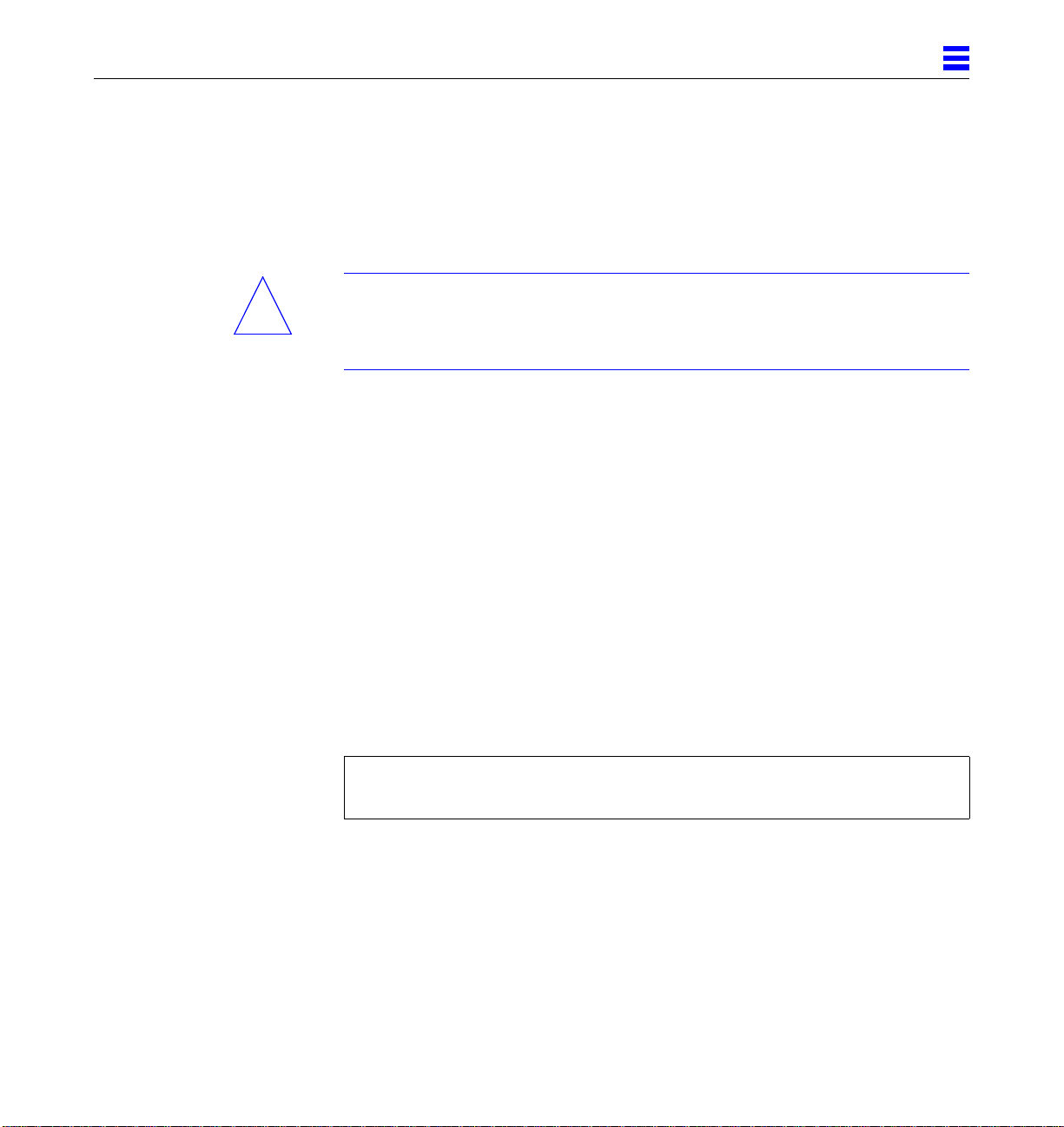
Figure 3-3 is a simplified block diagram of the CPU/Memory board. It includes
an Address Controller, 8 bit-sliced Data Controllers, a Bootbus Controller, onboard devices (including a Flash PROM, and SRAM), two CPU processor slots,
and slots for two memory banks of 8 SIMMs each.
3
CPU/Memory Boards and Components 3-5
Page 54

3
Memory (16 x 72 bit SIMMs)
Address
UltraSPARC
module
RAS/CAS
Address
controller
Control
Figure 3-3 CPU/Memory Board Simplified Block Diagram
Control
Address
Bootbus
Address
On-board devices
Centerplane Connector
3.4.1 Removing a Board
3.4.1.1 Removing a Board from a PoweredOnSystem
Bootbus
controller
UltraSPARC
module
Data
Data
Data (8)
controller
Data
Caution – Remove a board from a powered on system only after the ASR
!
3-6 Ultra Enterprise 6000/5000/4000Systems Manual—November 1996
software has disabled the board. If a board has not been disabled by the ASR
software, then the operating system should be halted and the system powered
off prior to board removal. See Chapter 12, “Powering Off and On” and then
see Section 3.4.1.2, “Removing a Board from a Nonpowered On System.”
Page 55

3
1. Ensure that the board has been disabled by the ASR software. See
Section 3.3, “Hot-Plug Feature.”
Once disabled by ASR, one of two results occurs:
• The three LEDs on the board are not lit (board has no power).
• The outer two green LEDs are not lit and the middle yellow LED is lit
(board in low power mode).
Note – System software operates such that the LED pattern described is the
same for a board that is component side down (installed in front of card cage)
or component side up (installed in rear of card cage).
2. Use a Phillips #1 screwdriver to mechanically release the board from the system card cage.
Insert the screwdriver into each quarter-turn access slot (the slots are located
on the left and right sides of the board front panel) and then turn a quarter
turn so that the arrow points to the unlocked position. See Figure 3-4.
Unlocked
Figure 3-4 Unlocking and Locking Quarter-Turn Access Slots
CPU/Memory Boards and Components 3-7
Locked
Page 56

3
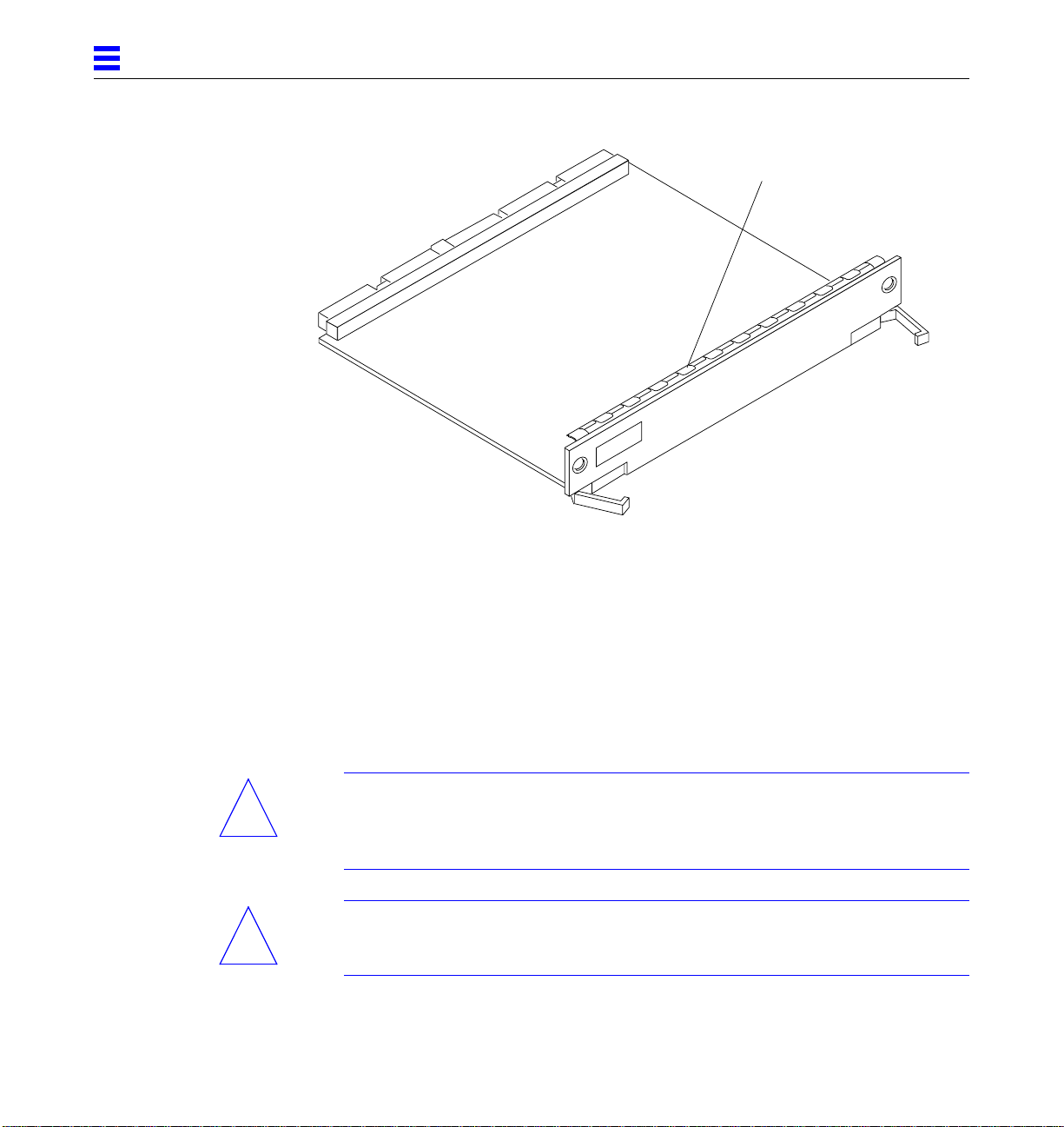
3. Pull the ends of both extraction levers outward simultaneously to unseat
the board centerplane connector from the centerplane receptacles.
See Figure 3-5 for the positioning of the levers.
Extraction lever
in extract/insert
position
Figure 3-5 CPU/Memory Board
4. If a board is not immediately replaced, a load board (Enterprise 6000
systems only) or a filler panel (Enterprise 4000 and 5000 systems only)
must be installed in its place.
See Section 3.2, “Filler Panels and Load Boards.”
3.4.1.2 Removing a Board from a NonpoweredOnSystem
1. Use a Phillips #1 screwdriver to mechanically release the board from the system card cage.
Insert the screwdriver into each quarter-turn access slot (the slots are located
on the left and right sides of the board front panel) and then turn a quarter
turn so that the arrow points to the unlocked position. See Figure 3-4.
3-8 Ultra Enterprise 6000/5000/4000Systems Manual—November 1996
Page 57

2. Pull the ends of both extraction levers outward simultaneously to release
the board from the centerplane receptacles.
See Figure 3-5 for the positioning of the levers.
3. If a board is not immediately replaced, a load board (Enterprise 6000
systems only) or a filler panel (Enterprise 4000 and 5000 systems only)
must be installed in its place.
See Section 3.2, “Filler Panels and Load Boards.”
3.4.2 Installing a Board
3.4.2.1 Board Slot Selection
Note – Logically there is no difference between the board slots in the front or
rear of the card cage, and each slot can accept any board type. It is suggested
that CPU/Memory boards be installed in the front slots, and I/O and disk
boards be installed in the rear slots because of cabling. Should the need arise,
however, any of these three board types can be placed in any of the numbered
board slots, with the exception of slot 1. Slot 1 should be used by the first I/O
board because it is the only slot connected to the onboard SCSI devices.
3
The first CPU/Memory board is placed in slot 0, followed sequentially by all
remaining even numbered slots. If there are boards remaining, they can be
installed sequentially in odd numbered slots, if available, in the system rear
(with the exception of slot 1 as noted above). See Figure 3-6 and Figure 3-7 for
board slot locations.
For CPU/Memory boards being placed in the rear of the system, ensure that
the component side is up. If the boards are placed in the front of the system,
ensure that the component side is down. See Figure 3-8.
CPU/Memory Boards and Components 3-9
Page 58

3
.
Slot #
10
12
14
Slot #
0
2
4
6
8
FrontView
Rear View
1
3
5
7
9
11
13
15
Figure 3-6 Enterprise 6000 Board Locations
3-10 Ultra Enterprise6000/5000/4000 Systems Manual—November 1996
Page 59

3
Slot #
Slot #
0
2
4
6
Front View
PCM
Rear View
1
3
5
7
Figure 3-7 Enterprise 5000/4000 Board Locations
3.4.2.2 Cooling and Power Issues
There should be one power/cooling module (PCM) for every two boards to
adhere to cooling and power requirements. The PCMs must be installed
adjacent to populated board slots to ensure the fan in the PCM can cool the
respective boards.
CPU/Memory Boards and Components 3-11
Page 60
3
Note – All empty board slots in Enterprise 4000 or 5000 systems must have a
filler panel installed to ensure proper cooling. All empty slots in Enterprise
6000 systems must have load boards installed.
3.4.2.3 PoweredorNonPoweredOn System
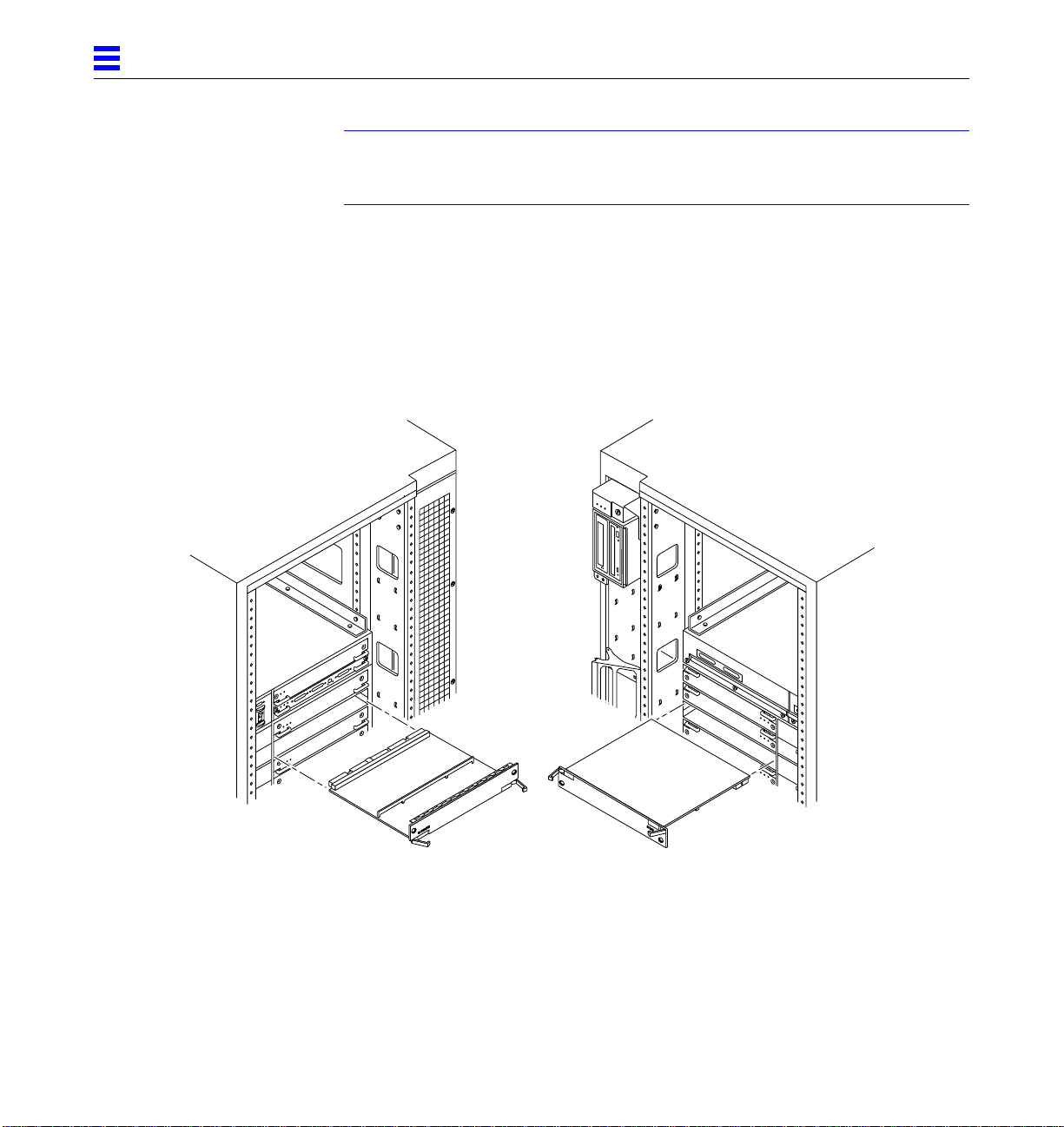
1. Carefully insert the board (component side down if in front; component
side up if in the rear) in the proper slot in the card cage, ensuring that the
board does not slip out of the left and right card guides.
See Figure 3-8.
Board orientation for insertion
in the cabinet rear (component
side up)
Figure 3-8 Board Replacement
3-12 Ultra Enterprise6000/5000/4000 Systems Manual—November 1996
Board orientation for insertion
in the cabinet front (component
side down)
Page 61
3
2. Ensure that both extraction levers are in the insert position (arrow
pointing outward), and that the quarter-turn access slots are unlocked
(arrow indicates unlocked position) as you slide the board toward the
centerplane receptacles.
See Figure 3-4 and Figure 3-5. The board will not seat fully unless the levers
are in this starting position and both quarter-turn access slots are unlocked.
Caution – DO NOT FORCE any board into a slot; it can cause damage to the
!
board and system. The board should insert and seat smoothly. If it binds,
remove the board and inspect the card cage slot for any obvious obstructions.
Also inspect both the board and the centerplane for bent pins or other damage.
3. Push the board into the card cage, then simultaneously press both
extraction levers to seat the board on the centerplane.
Pushing both levers simultaneously avoids twisting the board and bending
the connector pins, and mates the board centerplane connector to the
matching receptacle on the centerplane. Do not press on board front panel to
seat it—doing so will damage the connector pins.
4. Mechanically lock the board to the system chassis by inserting a Phillips
#1 screwdriver into each quarter-turn access slot and then turning to the
locked position.
See Figure 3-4.
5. Once the board has been installed, a message similar to the following will
be displayed on the monitor (if the system is powered on):
Example depicts screen output when a new CPU/Memory board has been
hot-plugged into slot 6 of an operating Enterprise system:
NOTICE: CPU Board Hotplugged into Slot 6
NOTICE: Board 6 is ready to remove
This screen output indicates that the board has been detected by the system
and is in the low power mode. Additionally, any subsequent prtdiag(1M)
output would include information for board slot 6. Again, note that the
system will not use the new board until the system is rebooted.
6. Reboot the system now or schedule a later time to reboot when system
disruption will be minimized.
CPU/Memory Boards and Components 3-13
Page 62

3
3.4.3 UltraSPARC Modules
Each CPU/Memory board has four connectors for UltraSPARC modules (up to
two modules per board, two connectors per module). For each module, there is
a connector with 144 pins and a connector with 288 pins. See Figure 3-9.
3.4.4 Handling Precautions
The following precautions should be exercised when handling UltraSPARC
modules:
• UltraSPARC modules are static-sensitive and a grounding wrist strap field
kit must be used when handling the modules.
• Always handle the modules by the edges and not by the smaller black heat
sinks that break easily if handled improperly.
• Do not handle the modules by touching the gold pins on the compression
connectors. Natural oils on the hands cause these connectors to oxidize and
corrode over a period of time, resulting in the need for module cleaning or
replacement.
288 pin connector
144 pin connector
Screws
(3 places)
Figure 3-9 UltraSPARC Module Connector Detail
3-14 Ultra Enterprise6000/5000/4000 Systems Manual—November 1996
Screws
(2 places)
Page 63

3.4.4.1 Removing a Module
Each module is locked to the main board with a single standoff and is
connected to the main board by two connectors. The pins within the connectors
are compressed to the corresponding board mating surfaces by a metal
compression bar which, when secured with screws, compresses the module
connector pins to the board mating surfaces. See Figure 3-10.
3
Figure 3-10 Ultra SPARC Module Connector Detail
1. Use the procedures in Section 3.4.1, “Removing a Board,” to remove the
applicable CPU/Memory board.
Warning – The heatsinks on the UltraSPARC modules may be hot. Use caution
when removing or installing UltraSPARC modules and avoid contact.
CPU/Memory Boards and Components 3-15
Page 64
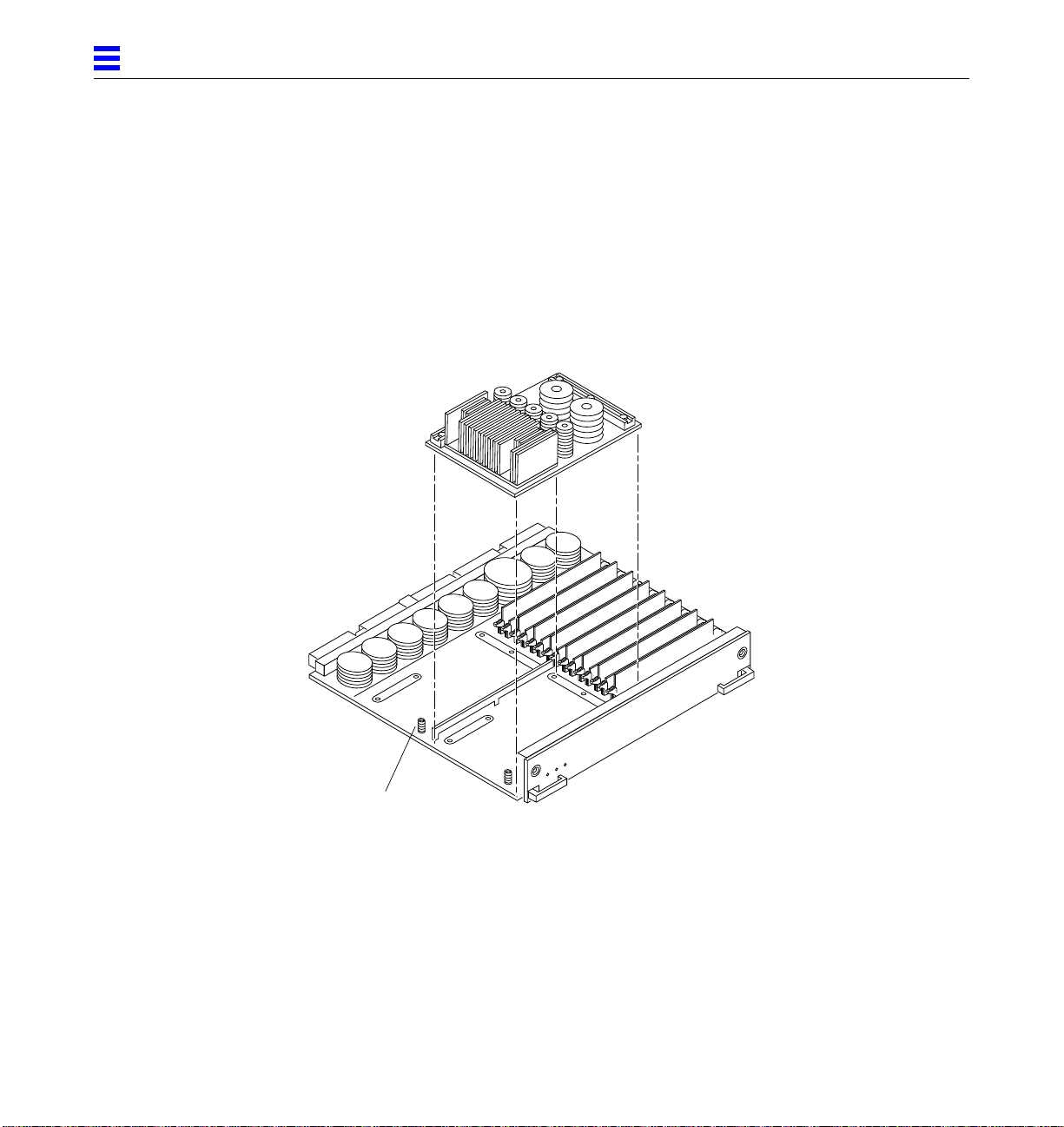
3
2. Use a 3/32 Hex driver to loosen all screws on each of the compression
connectors on the module to be removed (three screws for the 288 pin
connector, two screws for the 144 pin connector).
See Figure 3-9.
3. Lift the module straight up, off the board mating surface and the single
standoff that locks the module to the board.
Use pressure applied with fingers to assist in removing module from
standoff. See Figure 3-11.
Standoff,
1 per module
Figure 3-11 UltraSPARC Module Removal and Replacement
4. Place the module in an antistatic bag.
3-16 Ultra Enterprise6000/5000/4000 Systems Manual—November 1996
Page 65

3.4.4.2 Installing a Module
To maximize performance when installing UltraSPARC modules on a
CPU/Memory board, use all CPU 0 connectors on the lowest numbered slot to
the highest numbered slot. After this, if there are modules remaining, use the
CPU 1 connectors in the same order.
1. Take the UltraSPARC module out of the protective packaging and inspect
for dust on the connectors.
If necessary, clean the connectors with a dry, stiff toothbrush.
2. Remove the applicable CPU/Memory board as indicated in Section 3.4.1,
“Removing a Board.”
3. Inspect the board module mating surface. If the surface requires cleaning,
use a dry, stiff toothbrush to clean debris from the mating surfaces.
Note – There are miniature silver alignment pins on the compression
connectors which, when the module is properly seated, align with related
receptacles on the mating surfaces of the CPU/Memory board. In addition,
there is a gold standoff mounted on the CPU/Memory board opposite the
module’s smaller board connector. This acts as a standoff for the module as
well as an alignment pin.
3
4. Align the module over the two board receptacles using the single standoff
as well as the alignment pins located on the module compression
connector as a guide.
See Figure 3-10 and Figure 3-11.
5. Holding the module by the edges, rest it on the board standoff, aligning
the compression connectors with the screws.
Firmly but gently press the module straight down until the standoff post
snaps into place and the module connectors are fully seated.
6. Tighten the 3/32 hex screws of the module in two stages:
a. Tighten to 3 inch-pounds in the tightening sequence as follows:
CPU/Memory Boards and Components 3-17
Page 66
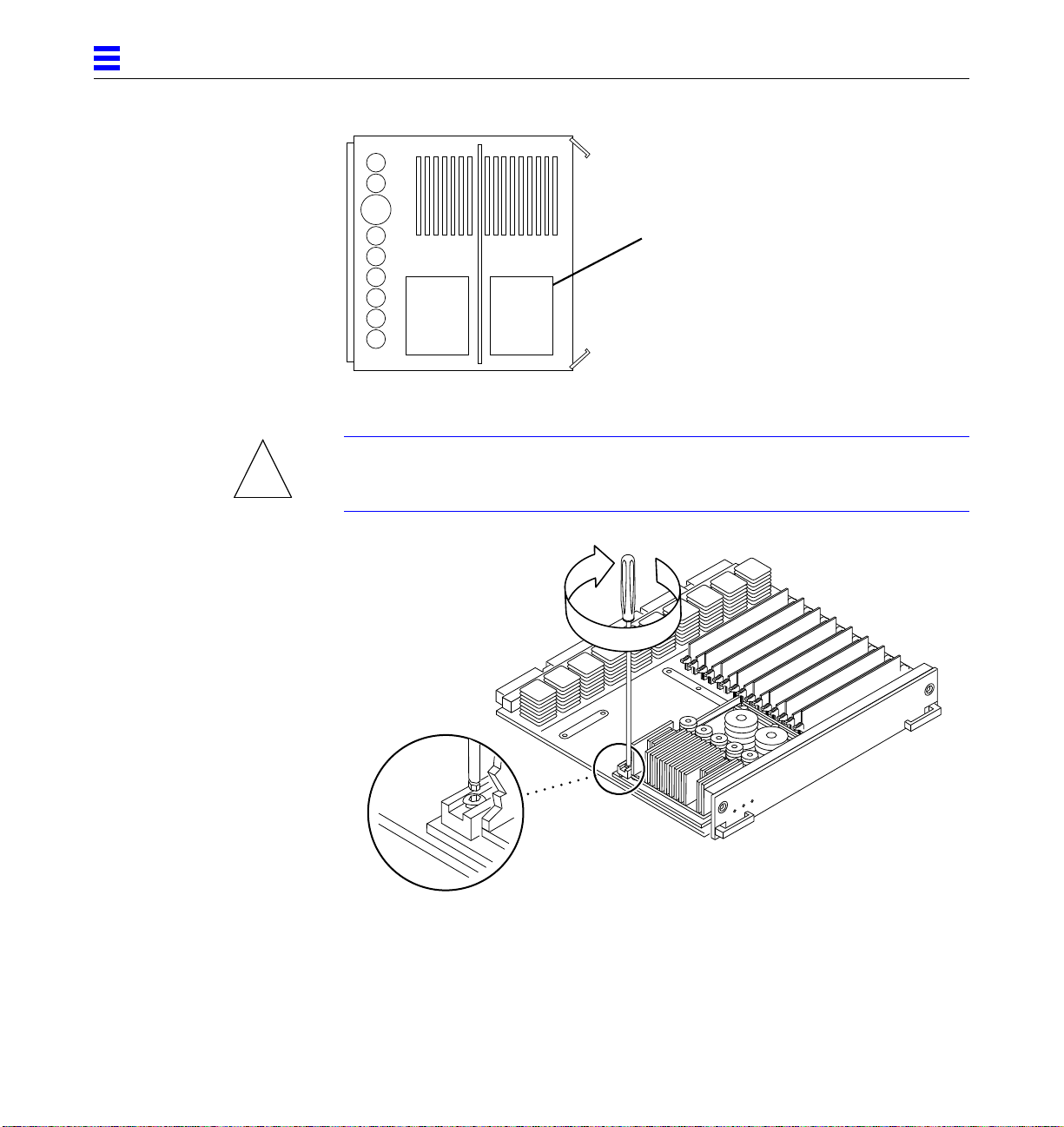
3
Tightening sequence
413
2
5
b. Tighten to 6 inch-pounds in the same tightening sequence.
Caution – Do not over-torque or under-torque the screws. Excessive force can
!
warp the connector. Insufficient force can cause an incomplete electrical
connection.
413
2
5
Figure 3-12 Tightening Compression Connector Screws
7. Use the procedures in Section 3.4.2, “Installing a Board,” to replace the
applicable CPU/Memory board.
3-18 Ultra Enterprise6000/5000/4000 Systems Manual—November 1996
Page 67

3.4.5 Memory Modules (SIMMs)
The CPU/Memory board has 16 SIMM sockets, which are divided into two
banks of 8 SIMMs each, Bank 0 and Bank 1. Bank 0 and Bank 1 SIMMs occupy
alternate slot locations; Bank 0 SIMMs are in the even numbered slots, and
Bank 1 SIMMs are in odd numbered slots. See Figure 3-13.
3
Bank 0
FHC
B0-J3100
B0-J3200
B0-J3300
B0-J3400
B0-J3500
B0-J3600
B0-J3700
B0-J3800
SRAM
B1-J3101
B1-J3201
B1-J3301
B1-J3401
B1-J3501
B1-J3601
B1-J3701
B1-J3801
SRAM
Bank 1
35W DC2DC
CPU1
288 connector
144 connector
CPU0
288 connector
144 connector
35W DC2DC
DC
DC
AC
720 centerplane connector
Figure 3-13 Layout of CPU/Memory Board
CPU/Memory Boards and Components 3-19
DC
DC
DC
DCDC
DC
Page 68

3
There are three types of SIMMs that can be used in both Bank 0 and Bank 1.
Each type is listed together with the DRAMs used in Table 3-1.
Table 3-1 SIMM vs. DRAM
SIMM DRAM
8 Mbyte 1 Mbyte x4
32 Mbyte 4 Mbyte x4
128 Mbyte 16 Mbyte x4
3.4.5.1 Removing a Memory Module
1. Remove the CPU/Memory board from which the SIMM is to be removed.
See Section 3.4.1, “Removing a Board.”
2. Attach a wrist strap and place an antistatic surface next to the system.
3. Locate the slot for the SIMM you need to replace.
See Figure 3-13.
3-20 Ultra Enterprise6000/5000/4000 Systems Manual—November 1996
Page 69

3
4. Eject the faulty SIMM by pressing down on the ejection levers on both
sides of the SIMM connector.
See Figure 3-14.
Figure 3-14 Ejecting a SIMM
5. Holding the SIMM by its edges, remove it from the slot and place it on an antistatic surface.
3.4.5.2 Installing a Memory Module
Requirements
All banks must have the same size SIMMs, however, SIMMs from different
manufactures are interchangeable in a single bank if the SIMMs all have the
same capacity and speed. Sort the SIMMs into banks of 8 using the same size
SIMMs.
CPU/Memory Boards and Components 3-21
Page 70

3
Maximizing Performance
The following guidelines will result in optimal memory interleaving across
boards for performance. These guidelines are for optimal performance and are
not requirements for a functional system. The guidelines apply to systems with
no SIMMS installed and when adding SIMMs to a system; if you are adding
SIMMs, you may need to move some SIMMs to meet the guidelines.
1. Install one bank on each board before installing the second bank on any board.
It does not matter whether the first bank is bank 0 or bank 1.
2. Begin with the largest density banks first (128 Mbyte SIMMs), continue
with medium sized banks (32 Mbyte SIMMs), and finish with the smallest
banks (8 Mbyte SIMMs).
3. If there is remaining memory, start filling the second banks on the boards
in the same order as the first banks.
Installation
1. Place the CPU/Memory board on which the SIMM is to be installed on an antistatic mat.
2. Carefully remove the new SIMM from its protective packaging and place
it on an antistatic surface.
The bag that the SIMM is packed in makes a good antistatic surface.
3. Press down on the ejector levers at both ends of the SIMM connector slot
that will receive the new SIMM.
The connector slot will not accept the SIMM unless the levers are in the
insert position. See Figure 3-15.
4. Align the SIMM with the slot.
Hold the SIMM by its edges and orient it so that the two notches at the
bottom of the SIMM line up with the two tabs in the SIMM connector. See
Figure 3-15.
5. Place your thumbs on the top edge of the SIMM and push the SIMM firmly into its connector.
See Figure 3-16.
3-22 Ultra Enterprise6000/5000/4000 Systems Manual—November 1996
Page 71

3
6. Lock the SIMM in place by pushing both ejector levers into the upright position.
See Figure 3-16.
7. Install the CPU/Memory board and detach the wrist strap.
See Section 3.4.2, “Installing a Board.”
8. As you reboot the system, watch for the system banner to verify that the
new memory is recognized by the system.
Notch alignment
Figure 3-15 Orienting a SIMM
CPU/Memory Boards and Components 3-23
Page 72

3
Figure 3-16 Installing a SIMM
3-24 Ultra Enterprise6000/5000/4000 Systems Manual—November 1996
Page 73

I/OBoardsandComponents
To protect both yourself and the equipment, make sure you follow precautions
in Chapter 2, “Safety Precautions and Tools Requirements.”
Safety Precautions page 2-1
Handling Boards and Assemblies page 3-2
Filler Panels and Load Boards page 3-3
SCSI Termination page 3-4
Hot-Plug Feature page 3-5
I/O Boards page 3-5
SBus Cards page 3-19
Graphics (UPA) Cards page 3-27
Fibre Cards page 3-31
Connectors page G-5
For your protection, also observe the following safety precautions when setting
up your equipment:
3
• Follow all cautions, warnings, and instructions marked on the equipment.
• Never push objects of any kind through openings in the equipment as they
may touch dangerous voltage points or short out components that could
result in fire or electric shock.
• Refer servicing of equipment to qualified personnel.
3-1
Page 74

3
3.1 Handling Boards and Assemblies
Caution – The chassis AC power cord must remain connected to ensure a
!
!
proper ground.
Caution – The I/O boards, their modules, and cards have surface-mount
components that can be broken by flexing the boards.
To minimize the amount of board flexing, observe the following precautions:
• Hold the board only by the edges near the middle of the board, where the
board stiffener is located. Do not hold the board only at the ends.
• When removing the board from an antistatic bag, keep the board vertical
until you lay it on the Sun ESD mat.
• Do not place the board on a hard surface. Use a cushioned antistatic mat.
The board connectors and components have very thin pins that bend easily.
• Do not use an oscilloscope probe on the components. The soldered pins are
easily damaged or shorted by the probe point.
• Transport the board in an antistatic bag.
• Be careful of small parts located on the component side of the board.
• Be careful not to drag boards across surfaces as board components are easily
damaged.
Caution – The heatsinks on the board can be damaged by incorrect handling.
!
!
!
3-2 Ultra Enterprise 6000/5000/4000Systems Manual—November 1996
Do not touch the heatsinks while installing or removing the board. Hold the
board only by the edges. If a heatsink is loose or broken, obtain a replacement
board.
Caution – When inserting the board into slot 4 or slot 10 of a 16-slot card cage,
lift the board slightly to avoid damage to the centerplane connectors.
Caution – The heatsinks on the board can be damaged by improper packaging.
When storing or shipping the board, ensure that the heatsinks have sufficient
protection.
Page 75

3.2 Filler Panels and Load Boards
All empty board slots in Enterprise systems must have either a filler panel or a
load board installed.
• Empty slots in Enterprise 5000 and 4000 systems must have a filler panel
installed.See Figure 3-1.
• Empty slots in Enterprise 6000 systems must have a load board installed.
See Figure 3-2.
Load boards and filler panels are inserted into a board slot with the
springfingers facing down if inserted in the front of the system; the
springfingers face up if inserted in the rear of the system.
3
Springfingers
Figure 3-1 Filler Panel (Enterprise 5000/4000 Only)
I/O Boards and Components 3-3
Page 76
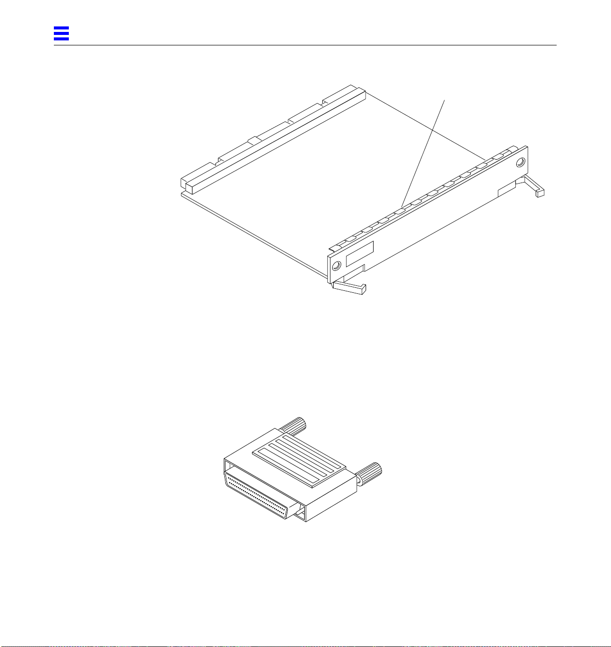
3
Springfingers
Figure 3-2 Load Board (Enterprise 6000 System Only)
3.3 SCSI Termination
The I/O board in slot 1 controls the internal SCSI tray devices. Therefore, the
external SCSI connector on the I/O board in slot 1 of a system must be
terminated with a SCSI terminator. See Figure 3-3.
Figure 3-3 SCSI Terminator
3-4 Ultra Enterprise 6000/5000/4000Systems Manual—November 1996
Page 77

3.4 Hot-Plug Feature
3
Enterprise systems have extensive error detection mechanisms, and an
Automatic System Reconfiguration (ASR) feature that enables the system to be
rebooted with failed components (such as CPUs, memory, or I/O) disabled.
When an error is detected, the system can be reconfigured so that the board
containing the failed components is placed in low power mode and is no
longer accessible.
Caution – The peripheral power supply provides the precharge voltages
required for hot-plug. Do not attempt hot-plug of a system component if the
power supply is missing or inoperative. Use prtdiag(1M) to determine the
status of the peripheral power supply.
Caution – If the message: NOTICE: Hot Plug not supported in this
system is displayed during boot, do NOT attempt hot-plug in this system or
damage to the hardware will occur.
The hot-plug feature enables you to insert a new board into a powered on
system, despite the system being “live,” or being supplied with electrical
power. When the hot-plug feature is used to add a board to a powered on
system, the system will not use the new board until the system is rebooted.
3.5 I/O Boards
Enterprise systems support two types of I/O boards: SBus and Graphics. See
Figure 3-4 through Figure 3-7.
The SBus I/O board includes two SYSIO ASICs that provide two SBuses:
• One for two plug-in SBus cards and two fiber interfaces
• One for one plug-in SBus card and the on-board devices (10/100Mbyte TPE
and Single-ended Fast/Wide SCSI)
Note – SBus connector slots 1 and 2 on the SBus I/O board can accommodate a
double-wide SBus card.
I/O Boards and Components 3-5
Page 78

3
The Graphics I/O board includes one SYSIO ASIC that provides a single SBus
for two plug-in SBus cards, two fiber interfaces, and the on-board devices
(10/100Mbyte TPE and Single-ended Fast/Wide SCSI).
3.5.1 tpe-link-test? Variable
If the system cannot communicate with a network, the tpe-link-test?
settings for the on-board Ethernet ports may be incompatible with the setting
at the network hub. The tpe-link-test? variable is set separately for the onboard Ethernet port on each I/O board. The variable is also set for any SBus
Ethernet cards in the system.
If you have problems verifying connection between Sun equipment and your
hub, verify that your hub also has the link test function enabled.
See Section 8.5.3.2, “printenv Command,” for information about displaying
configuration variables and Section 8.6.1, “Failure of Network
Communications,” for additional tpe-link-test? information. Also, refer to
the manual provided with your hub.
3-6 Ultra Enterprise 6000/5000/4000Systems Manual—November 1996
Page 79

3
Single-ended
SCSI connector
Fibre 0 Fibre 1
SOC
SBus connector 2
J2500
FHC SYSIO
SBus connector 1
TPE
PHY
SYSIO
MII connector
FEPS
SBus connector 0
RISC
RISC
DCDC
AC
Figure 3-4 SBus I/O Board Components Locations
I/O Boards and Components 3-7
DC
720 Centerplane connector
DC
DCDC
DC
DC
Page 80

3
Fibre 0 Fibre 1
Single-ended
SCSI connector
TPE
PHY
MII connector
SOC
SBus connector 2
J2500
FHC SYSIO
DCDC
AC
Figure 3-5 Graphics I/O Board Components Locations
Graphics (UPA) connector
DC
720 Centerplane connector
DC
RISC
FEPS
SBus connector 0
DCDC
DC
DC
3-8 Ultra Enterprise 6000/5000/4000Systems Manual—November 1996
Page 81
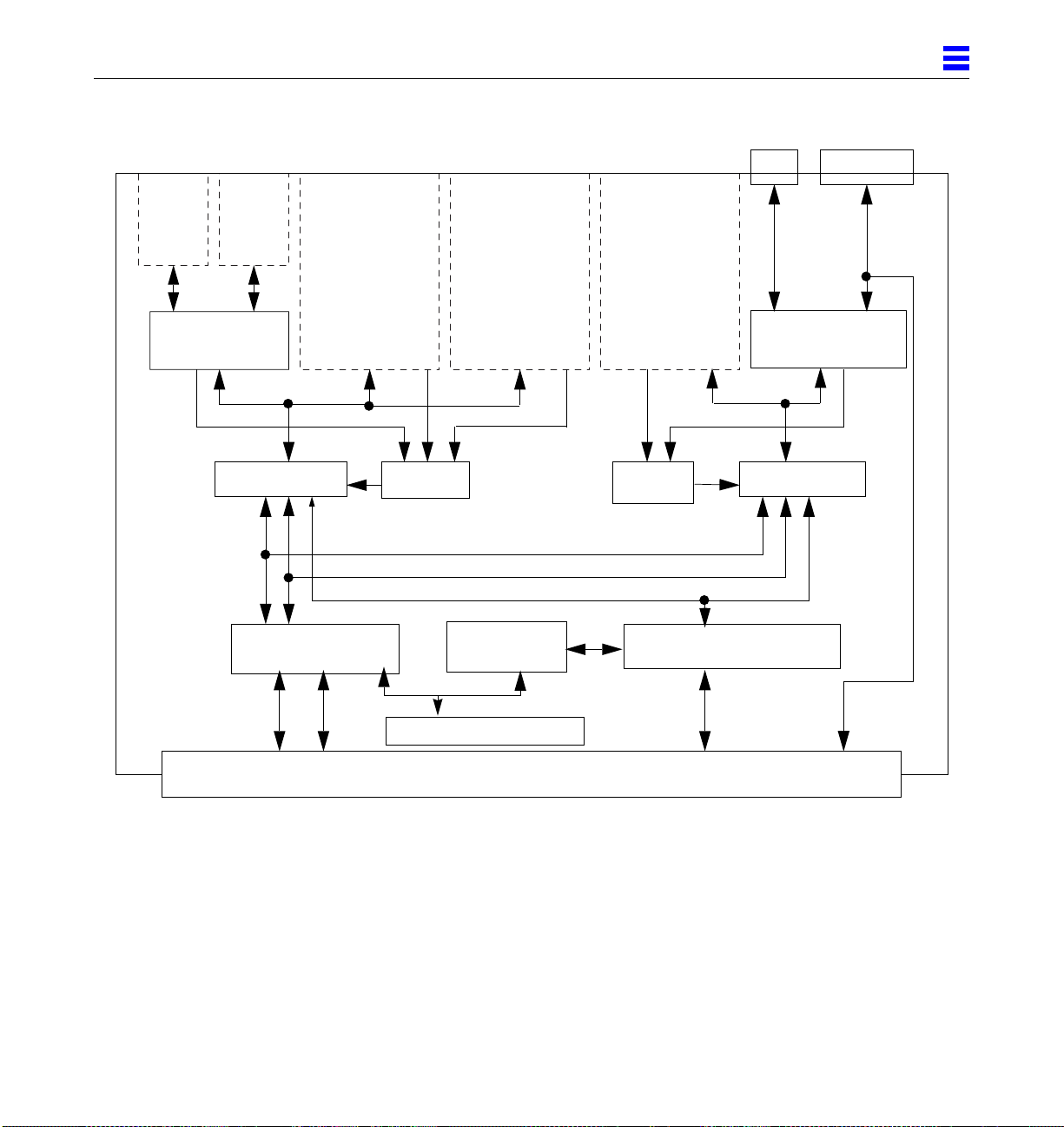
3
Fiber
interface
SOC
slot 13 (d)
Fiber
interface
SYSIO A
Address
controller
Control
SBus
card
Address
SBus
card
RISC
Control
Address
Data
Bootbus
controller
Bootbus
On-board devices
SBus
card
slot 0slot 1slot 2
SBus
RISC
Data controller (8)
Data
TPE
10/100MB
Ethernet
FEPS
slot 3
SYSIO B
Single-ended
SCSI Conn
Fast/Wide
SCSI
Centerplane connector
Figure 3-6 SBus I/O Board Simplified Block Diagram
I/O Boards and Components 3-9
Page 82

3
Fiber
interface
SOC
slot 13 (d)
Fiber
interface
SYSIO
Address
Control
controller
SBus
card
Address
UPA
connector
SBus
RISC
Control
Address
Data
Bootbus
controller
Bootbus
On-board devices
SBus
card
slot 0slot 2
Data controller (8)
Data
TPE
Single-ended
SCSI Conn
10/100MB
Ethernet
FEPS
slot 3
Fast/Wide
SCSI
Centerplane connector
Figure 3-7 Graphics I/O Board Simplified Block Diagram
3-10 Ultra Enterprise6000/5000/4000 Systems Manual—November 1996
Page 83
3.5.2 Removing a Board
3.5.2.1 Removing a Board from a PoweredOnSystem
Caution – Remove a board from a powered on system only after the ASR
software has disabled the board. If a board has not been disabled by the ASR
software, then the operating system should be halted and the system powered
off prior to board removal. See Chapter 12, “Powering Off and On” and then
Section 3.5.2.2, “Removing a Board from a Nonpowered On System.”
1. Ensure that the board has been disabled by the ASR software. See
Section 3.4, “Hot-Plug Feature.”
Once disabled by ASR, one of two results occurs:
• The three LEDs on the board are not lit (board has no power).
• The outer two green LEDs are not lit and the middle yellow LED is lit
(board in low power mode).
Note – System software operates such that the LED pattern described is the
same for a board that is component side down (installed in front of card cage)
or component side up (installed in rear of card cage).
3
2. Unfasten any cable connectors from the front panel and set them aside.
Label cables to identify them for reconnection later.
3. Use a Phillips #1 screwdriver to mechanically release the board from the system card cage.
Insert the screwdriver into each quarter-turn access slot (the slots are located
on the left and right sides of the board‘s front panel) and then turn a quarter
turn so that the arrow points to the unlocked position. See Figure 3-8.
I/O Boards and Components 3-11
Page 84

3
Unlocked Locked
Figure 3-8 Unlocking and Locking Quarter-Turn Access Slots
4. Pull the ends of both extraction levers outward simultaneously to unseat
the board centerplane connector from the centerplane receptacles.
See Figure 3-9 for positioning of extraction levers.
3-12 Ultra Enterprise6000/5000/4000 Systems Manual—November 1996
Page 85

SBus I/O board
3
Extraction levers in
extract/insert position
Graphics I/O board
Figure 3-9 I/O Boards
I/O Boards and Components 3-13
Page 86

3
5. If a board is not immediately replaced, a load board (Enterprise 6000
systems only) or a filler panel (Enterprise 4000 and 5000 systems only)
must be installed in its place.
See Section 3.2, “Filler Panels and Load Boards.”
3.5.2.2 Removing a Board from a NonpoweredOnSystem
1. Use a Phillips #1 screwdriver to mechanically release the board from the system card cage.
Insert the screwdriver into each quarter-turn access slot (the slots are located
on the left and right sides of the board front panel) and then turn a quarter
turn so that the arrow points to the unlocked position. See Figure 3-8.
2. Unfasten any cable connectors from the front panel and set them aside.
Label cables to identify them for reconnection later.
3. Pull the ends of both extraction levers outward simultaneously to unseat
the board from the centerplane receptacles.
See Figure 3-9 for positioning of extraction levers.
3.5.3 Installing a Board
3.5.3.1 Board Slot Selection
Note – Logically there is no difference between the board slots in the front or
rear of the card cage, and each slot can accept any board type. It is suggested
that CPU/Memory boards be installed in the front slots, and I/O and disk
boards be installed in the rear slots because of cabling. Should the need arise,
however, any of these three board types can be placed in any of the numbered
board slots, with the exception of slot 1. Slot 1 should be used by the first I/O
board because it is the only slot connected to the onboard SCSI devices.
The first CPU/Memory board is placed in slot 0, followed sequentially by all
remaining even numbered slots. If there are boards remaining, they can be
installed sequentially in odd numbered slots, if available, in the system rear
(with the exception of slot 1 as noted above). See Figure 3-10 and Figure 3-11.
3-14 Ultra Enterprise6000/5000/4000 Systems Manual—November 1996
Page 87

For I/O boards being placed in the rear of the system, ensure that the
component side is up. If the boards are placed in the front of the system,
ensure that the component side is down. See Figure 3-12.
.
3
Slot #
10
12
14
Slot #
0
2
4
6
8
Front View
Rear View
1
3
5
7
9
11
13
15
Figure 3-10 Enterprise 6000 Board Locations
I/O Boards and Components 3-15
Page 88

3
Slot #
Slot #
0
2
4
6
PCM
Front View
Rear View
1
3
5
7
Figure 3-11 Enterprise 5000/4000 Board Locations
3.5.3.2 Cooling and Power Issues
There should be one power/cooling module (PCM) for every two boards to
adhere to cooling and power requirements. The PCMs must be installed
adjacent to populated board slots to ensure the fan in the PCM can cool the
respective boards.
3-16 Ultra Enterprise6000/5000/4000 Systems Manual—November 1996
Page 89

Note – All empty board slots in Enterprise 4000 or 5000 systems must have a
filler panel installed to ensure proper cooling. All empty slots in Enterprise
6000 systems must have load boards installed.
3.5.3.3 PoweredorNonpoweredOn System
1. Carefully insert the board (component side down if in front; component
side up if in the rear) in the proper slot in the card cage, ensuring that the
board does not slip out of the left and right card guides.
See Figure 3-12
3
Board orientation for insertion
in the cabinet rear (component
side up)
Figure 3-12 Board Replacement
I/O Boards and Components 3-17
Board orientation for insertion
in the cabinet front (component
side down)
Page 90

3
2. Ensure that both extraction levers are in the insert position (arrow
pointing outward), and that the quarter-turn access slots are unlocked
(arrow indicates unlocked position) as you slide the board toward the
centerplane receptacles.
See Figure 3-8 and Figure 3-9. The board will not seat fully unless the levers
are in this starting position and the access slots are unlocked.
Caution – DO NOT FORCE any board into a slot; this can cause damage to the
!
board and system. The board should insert and seat smoothly. If it binds,
remove the board and inspect the card cage slot for any obvious obstructions.
Also inspect both the board and the centerplane for bent pins or other damage.
3. Push the board into the card cage, then simultaneously press both
extraction levers to seat the board on the centerplane.
Pushing both levers simultaneously avoids twisting the board and bending
the connector pins, and mates the board centerplane connector to the
matching receptacle on the centerplane. Do not press on board front panel to
seat it—doing so will damage the connector pins.
4. Mechanically lock the board to the system chassis by inserting a Phillips
#1 screwdriver into each quarter-turn access slot and then turning to the
locked position.
See Figure 3-8.
5. Replace or connect all necessary cables to the front of the board.
Note – The I/O board in slot 1 controls the internal SCSI tray devices.
Therefore, the external SCSI connector on the I/O board in slot 1 of a system
must be terminated with a SCSI terminator. See Figure 3-3.
6. Terminate the board SCSI connector if required, see above note.
7. Once the board has been installed, a message similar to the following will
be displayed on the monitor (if the system is powered on):
Example depicts screen output when a new I/O board has been hot-plugged
into slot 6 of an operating Enterprise system:
NOTICE: I/O Board Hotplugged into Slot 6
NOTICE: Board 6 is ready to remove
3-18 Ultra Enterprise6000/5000/4000 Systems Manual—November 1996
Page 91
This screen output indicates that the board has been detected by the system
and is in the low power mode. Additionally, any subsequent prtdiag(1M)
output would include information for board slot 6. Again, note that the
system will not use the new board until the system is rebooted.
8. Reboot the system now or schedule a later time to reboot when system
disruption will be minimized.
3.5.4 SBus Cards
There are three SBus card locations on the SBus I/O board; the Graphics I/O
board has two. Figure 3-13 shows the SBus card locations for both types of
boards.
3
I/O Boards and Components 3-19
Page 92
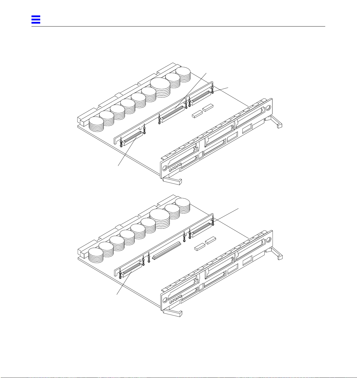
3
SBus 1
SBus 2
SBus I/O board
SBus 0
SBus 2
SBus 0
Figure 3-13 I/O Board SBus Card Locations
3-20 Ultra Enterprise6000/5000/4000 Systems Manual—November 1996
Graphics I/O board
Page 93

3.5.4.1 Plastic Standoffs
Plastic standoffs lock the SBus and graphics (UPA) cards to the I/O boards. See
Figure 3-14.
• To unlock a standoff, pull up the tip insert.
• To lock a standoff, first ensure that the module or card rests on the standoff
flange, then press down the tip insert.
3
Standoff
UnlockedLocked
Figure 3-14 Locking and Unlocking Standoffs
SBus/graphics (UPA) cards
Standoff
Tip insert
Flange
3.5.4.2 Removing an SBus Card
1. Use the procedures in Section 3.5.2, “Removing a Board,” to
remove the applicable I/O board.
2. Use Figure 3-13 to locate the card to be removed.
I/O Boards and Components 3-21
Page 94

3
3. Remove the two screws that secure the SBus card to the back panel.
Save the screws for installation of a replacement SBus card or a filler panel.
4. Unlock the SBus card by pulling up the tips of the two standoffs.
See Figure 3-14.
5. Hold the card by the edges near the connector and gently rock the card
back and forth to loosen it from the socket.
You may have to remove the SBus cards or the FFB card next to this card in
order to have enough room to hold onto the SBus card being removed.
Caution – The connector housing may break if the SBus card is tilted too far.
!
6. Lift the SBus card from the socket at an angle while guiding the face plate
out from the back panel opening.
See Figure 3-15.
Figure 3-15 Removing or Installing an SBus Card
3-22 Ultra Enterprise6000/5000/4000 Systems Manual—November 1996
Page 95

7. Place the SBus card in an antistatic bag.
8. If the SBus card is not immediately replaced, install a filler panel (part
number 340-2305) on the I/O board back panel opening. To secure the
filler panel, use the screws that were removed in Step 3.
Caution – Be sure to install the filler panel right-side up. Installing it upside
!
down creates a gap at the top edge of the SBus slot opening that can impair
system cooling and FCC regulatory compliance.
9. Replace the I/O board. Use the procedures in Section 3.5.3, “Installing a
Board.”
3.5.4.3 PreparingtoInstall an SBus Card
Note – If the new SBus card does not have an adapter plate or the Link
Integrity Test feature, proceed to “Installing an SBus Card” on page 3-26.
1. Attach a wrist strap and take the SBus card out of the protective
packaging and place the SBus card on an antistatic mat.
3
2. Remove the adapter bracket from the SBus card rear panel.
See Figure 3-16. Remove the two screws securing the adapter to the card
rear panel (the adapter bracket and the screws are not needed for this
installation).
Remove adapter
Remove screws
Figure 3-16 SBus Card Rear Panel with Adapter
I/O Boards and Components 3-23
Page 96

3
3. Remove the black plastic card retainer shipped with the card.
See Figure 3-17. Spread the ends of the retainer apart to remove it from the
card (the retainer is not needed for this installation).
Card retainer
Figure 3-17 Card Retainer
Link Integrity Test
1. Ensure that the SBus card is on an antistatic mat.
2. For DSBE/S and FSBE/S cards: remove the two outer retaining screws (see
Figure 3-18), but do NOT remove the middle screw or the springfinger.
Use a #0 Phillips screwdriver and a 3/16 nut driver or socket wrench.
3. For DSBE/S and FSBE/S cards, configure jumper J0302 for Link Integrity
Test functionality. See Figure 3-18 (DSBE/S) or Figure 3-19 (FSBE/S).
a. Put the shunt over both pins to disable the Link Integrity Test. See
Figure 3-20 “Disabled.”
b. Put the shunt in one pin to enable the Link Integrity Test. See
Figure 3-20 “Enabled.”
Caution – If you choose to disable the test, it must be disabled both at the hub
!
3-24 Ultra Enterprise6000/5000/4000 Systems Manual—November 1996
and at the SBus card. In the event of “loss of carrier” or “not responding”
problems, check the status of the link enable on both the SBus card and the
hub.
Page 97

Jumper J0302
3
Springfinger
Back panel
Figure 3-18 DSBE/S SBus Card
J0302
Figure 3-19 FSBE/S SBus Card
I/O Boards and Components 3-25
Phillips screw
Jackscrews
Page 98
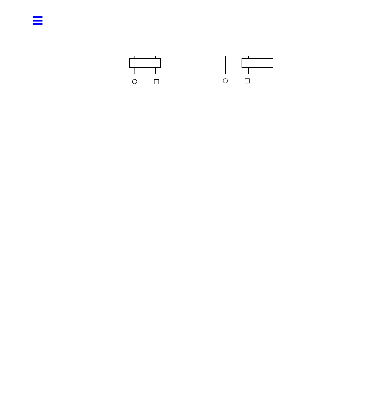
3
2
Disabled
Figure 3-20 Disabling and Enabling the Link Integrity Test
1
3.5.4.4 Installing an SBus Card
1. Use the procedures in Section 3.5.2, “Removing a Board,” to
remove the applicable I/O board.
2. Use Figure 3-13 to locate the SBus connector for the card that is to be
installed.
3. If a filler panel covers the back panel SBus slot, remove the two screws
and detach the filler panel.
Retain the screws to attach the SBus card to the back panel, unless the card
has a wide connector, or set of connectors.
4. Unlock the tip insert of the two standoffs for the SBus slot.
See Figure 3-14.
5. Attach a wrist strap and take the SBus card out of the protective
packaging. Inspect the pins in the connector to make sure they are not
bent.
6. Hold the SBus card at an angle and guide the SBus card face plate under
the springfingers and against the rear face of the I/O board front panel.
See Figure 3-15 on page 3-22. The I/O connectors of the SBus card should be
visible through the opening in the back panel.
2
Enabled
1
7. Hold the card by the edges nearest the SBus connector and place the card over the two standoffs.
8. Hold the SBus card by the edges near the connector and firmly but gently
press the card down until the connector is fully seated.
To align the connector and socket, push the card toward the I/O board back
panel.
3-26 Ultra Enterprise6000/5000/4000 Systems Manual—November 1996
Page 99

Caution – Do not rock the card onto the socket; the plastic connector housing
!
may break.
9. Press each corner of the SBus card to ensure that it rests on the collar of the standoff.
10. Press down on the tip insert of each standoff to lock the card in place.
11. Replace and tighten the back panel screws to secure the SBus card to the I/O board back panel.
12. Replace the I/O board using the procedures described in Section 3.5.3,
“Installing a Board.”
3.5.5 Graphics (UPA) Cards
The Graphics I/O board contains a single connector that accommodates
graphics (UPA) cards. See Figure 3-21.
3
UPA connector
Figure 3-21 Graphics (UPA) Card Connector Location
I/O Boards and Components 3-27
Page 100
3
3.5.5.1 Removing a Graphics (UPA) Card
1. Use the procedures in Section 3.5.2, “Removing a Board,” to remove the
applicable Graphics I/O board.
2. Locate the card. See Figure 3-22.
3. Remove the two screws that secure the card to the Graphics I/O board front panel.
Save the screws for installation of a replacement card or a filler panel.
4. Unlock the card by pulling up the tips of the two standoffs.
See Figure 3-14.
5. Hold the card by the edges near the connector and gently rock the card
back and forth to loosen it from the socket.
You may have to remove the SBus cards next to this card in order to have
enough room to hold onto the graphics (UPA) card being removed.
Caution – The connector housing may break if the card is tilted too far.
!
6. Lift the card from the socket at an angle while guiding the face plate out
from the back panel opening.
See Figure 3-22.
3-28 Ultra Enterprise6000/5000/4000 Systems Manual—November 1996
 Loading...