

Page 1

Sun™Datacenter Switch 3456
Installation Guide
Sun Microsystems, Inc.
www.sun.com
Part No. 820-4730-11
December 2008, Revision A
Submit comments about this document at: http://www.sun.com/hwdocs/feedback
Page 2

Copyright 2008Sun Microsystems,Inc., 4150Network Circle, SantaClara, California95054, U.S.A.All rightsreserved.
Sun Microsystems,Inc. hasintellectual property rightsrelating totechnology embodiedin theproduct that is described in this document. In
particular,and withoutlimitation, theseintellectual property rights may include one or more ofthe U.S.patents listedat
http://www.sun.com/patents and one ormore additionalpatents orpending patentapplications inthe U.S.and inother
countries.Unpublished -rights reservedunder theCopyright Lawsof theUnited States..
This distributionmay includematerials developedby thirdparties.Parts ofthe product maybe derivedfrom BerkeleyBSD systems,licensed
from theUniversity ofCalifornia. UNIXis aregistered trademark in the U.S. and in other countries, exclusively licensed through X/Open
Company, Ltd.
Sun, SunMicrosystems, theSun logo,SunService, andThe Networkis theComputer are trademarksor registered trademarksof Sun
Microsystems, Inc.in theU.S. andother countries.TheOPEN LOOKand Sun(TM)Graphical UserInterface wasdeveloped bySun
Microsystems, Inc.for itsusers andlicensees.
Sun acknowledgesthe pioneeringefforts ofXerox in researchingand developingthe conceptof visualor graphicaluser interfacesfor the
computer industry.Sun holdsa non-exclusivelicense from Xeroxto theXerox Graphical User Interface, which license also covers Sun’s
licensees whoimplement OPENLOOK GUIsand otherwisecomply withSun’s writtenlicense agreements.
Use ofany spareor replacement CPUsis limitedto repairor one-for-one replacementof CPUsin products exportedin compliancewith U.S.
export laws.Use ofCPUs asproduct upgradesunless authorizedby theU.S. Governmentis strictlyprohibited.
DOCUMENTATION IS PROVIDED "AS IS" AND ALL EXPRESS OR IMPLIED CONDITIONS, REPRESENTATIONS AND WARRANTIES,
INCLUDING ANY IMPLIED WARRANTY OFMERCHANTABILITY, FITNESS FOR A PARTICULAR PURPOSE OR NON-INFRINGEMENT,
ARE DISCLAIMED, EXCEPT TO THE EXTENT THAT SUCH DISCLAIMERS ARE HELD TO BE LEGALLY INVALID.
Copyright ©2008 SunMicrosystems, Inc.,4150 NetworkCircle, Santa Clara, California 95054, Etats-Unis. Tous droits réservés.
Sun Microsystems,Inc. détientles droits depropriété intellectuelsrelatifs à la technologie incorporée dans le produit qui est décrit dans ce
document. Enparticulier,et cesans limitation,ces droits de propriété intellectuellepeuvent inclure un ou plus des brevetsaméricains listésà
l’adresse http://www.sun.com/patent set un ou les brevets supplémentairesou lesapplications debrevet en attente aux Etats - Unis et
dans lesautres pays.Nonpublie -droits réservés selon la législation des Etats-Unis sur le droit d’auteur.
Cette distributionpeut comprendre descomposants développéspar destierces parties.Desparties dece produit pourrontêtre dérivées des
systèmes BerkeleyBSD licenciéspar l’Universitéde Californie.UNIX estune marquedéposée auxEtats-Unis etdans d’autres payset licenciée
exclusivement parX/Open Company, Ltd.
Sun, Sun Microsystems, le logo Sun, SunService, et The Network is the Computer sont des marques defabrique oudes marques déposées de
Sun Microsystems,Inc. auxEtats-Unis etdans d’autres pays.L’interface d’utilisation graphiqueOPEN LOOKet Sun(TM)a étédéveloppée par
Sun Microsystems,Inc. pourses utilisateurset licenciés.
Sun reconnaîtles efforts depionniers deXerox pourla recherche etle développementdu conceptdes interfacesd’utilisation visuelle ou
graphique pourl’industrie del’informatique. Sundétient unelicense nonexclusive deXerox surl’interface d’utilisationgraphique Xerox, cette
licence couvrantégalement leslicenciés deSun quimettent enplace l’interfaced’utilisation graphiqueOPEN LOOKet qui,en outre,se
conforment auxlicences écritesde Sun.
L’utilisationde piecesdetachees oud’unites centralesde remplacement est limitee aux reparations oua l’echangestandard d’unites centrales
pour lesproduits exportes,conformement ala legislationamericaine enmatiere d’exportation. Sauf autorisation par les autorites des EtatsUnis, l’utilisationd’unites centralespour procedera desmises ajour deproduits est rigoureusement interdite.
LA DOCUMENTATION EST FOURNIE "EN L’ETAT" ET TOUTES AUTRES CONDITIONS, DECLARATIONS ET GARANTIES EXPRESSES
OU TACITES SONT FORMELLEMENTEXCLUES, DANSLA MESUREAUTORISEE PARLA LOIAPPLICABLE, YCOMPRIS NOTAMMENT
TOUTE GARANTIE IMPLICITE RELATIVE A LA QUALITE MARCHANDE, A L’APTITUDE A UNE UTILISATION PARTICULIERE OU A
L’ABSENCE DE CONTREFACON.
Please
Recycle
Page 3

Contents
Preface xi
1. Cautions and Considerations 1
Chassis Weight 1
Moving the Chassis 1
Loading by the Chassis 2
Chassis Activity Dimensions 3
Heat Considerations 3
Air Temperature 3
Surface Temperature 4
Other Objects’ Temperatures 4
Hot and Cold Aisles 4
Electrical Considerations 4
Main Power 4
Bus Power 5
Pin Power 5
2. Partial Configuration 7
Complete and Base Configurations 7
Configuration Considerations 8
iii
Page 4

Filler Panels 8
Line Card Distribution 8
Power Supplies 8
Component Distribution 9
3. Preparing for Installation 11
Final Location Checklists 11
Power Checklist 11
Network Checklist 12
Cabling Checklists 12
Power Cabling Checklist 12
Network Cabling Checklist 12
Spacing Checklist 12
Loading Checklist 13
Environmental Checklist 13
Personnel Checklist 13
Tools Checklists 13
Installation Tools Checklist 14
Administration Tools Checklist 14
Maintenance Tools Checklist 14
Path to Final Location 15
Security Systems 15
Signage 15
Carpets 15
Grades 16
Elevators 16
Doors 16
Thresholds and Gaps 17
Path 17
iv Sun Datacenter Switch 3456 Installation Guide • December 2008
Page 5

Surface 17
Turns 17
Receiving Area 18
Equipment 18
Cleanliness 18
Personnel 18
Number of People 19
Tasks and Roles 19
Mindset 20
Safety 20
Methodical Approach 20
Diligent Attitude 21
Installation and Maintenance Tools 21
Standard Tools 21
4. Installation Sequence 23
Installation Sequence 23
5. Unpacking the Chassis 25
Unpacking the Chassis 25
▼ To Remove Shipping Crate Components 26
▼ To Remove the Plastic Envelope 29
▼ To Fit the Ramp 30
▼ To Unsecure the Chassis 31
▼ To Roll Out the Chassis 32
6. Installing the Chassis 35
Installing the Chassis 35
▼ To Move to the Final Location 35
▼ To Level the Chassis 36
Contents v
Page 6

▼ To Secure the Chassis 39
▼ To Remove the Power Supply Filler Panels 39
▼ To Remove the Line Card Filler Panels 40
▼ To Install the Line Card Filler Panels 41
Inspecting the Chassis 43
▼ To Verify Electrical Leakage 43
▼ To Verify Electrical Continuity 45
7. Inspecting and Repairing Pins 47
Midplane Filler Strips 47
Inspecting Pins 48
Tools 48
▼ To Inspect the Pins on the Rear Side of the Midplane 48
▼ To Inspect the Pins on the Front Side of the Midplane 51
Repairing and Replacing Pins 54
Tools 54
▼ To Remove Pins 54
▼ To Remove a Pin With Needle-Nose Pliers 56
▼ To Insert Pins 57
8. Installing Fabric Cards 59
Fabric Card Considerations 59
Inspecting Fabric Cards 60
▼ To Inspect the Fabric Card iTRAC Connectors 60
▼ To Inspect the Fans 61
▼ To Inspect the Retainers 62
Installing Fabric Cards Into the Chassis 63
▼ To Install the Midplane Stiffener 63
▼ To Install the Fabric Cards 65
vi Sun Datacenter Switch 3456 Installation Guide • December 2008
Page 7

▼ To Remove the Midplane Stiffener 66
Fabric Card Administrative Commands 68
▼ To Enable Fabric Cards 68
▼ To Disable Fabric Cards 68
▼ To Enable Fabric Card IPMB Buses 69
▼ To Disable Fabric Card IPMB Buses 69
▼ To Enable Fabric Card Standby Power 69
▼ To Disable Fabric Card Standby Power 69
▼ To Fully Power On Fabric Cards 70
▼ To Power Down Fabric Cards to a Standby State 70
▼ To Read Fabric Card FRUID Information 70
9. Installing Line Cards 73
Line Card Considerations 73
Inspecting Line Cards 74
▼ To Inspect the Line Card iTRAC Connectors 74
▼ To Inspect the iPASS Connectors 75
▼ To Inspect the Retainers 76
Installing Line Cards Into the Chassis 77
▼ To Install the Line Cards 77
Line Card Administrative Commands 78
▼ To Enable Line Cards 78
▼ To Disable Line Cards 79
▼ To Enable Line Card IPMB Buses 79
▼ To Disable Line Card IPMB Buses 79
▼ To Enable Line Card Standby Power 79
▼ To Disable Line Card Standby Power 80
▼ To Fully Power On Line Cards 80
▼ To Power Down Line Cards to a Standby State 80
Contents vii
Page 8

▼ To Read Line Card FRUID Information 81
10. Powering On 83
Installing Power Supplies 83
▼ To Install Power Supplies 83
Preparing Power Supplies 85
▼ To Attach Power Cables 85
Power Supply Administrative Commands 86
▼ To Power On Power Supplies 86
▼ To Power Down Power Supplies 87
▼ To Verify Power Supply Status 87
Working With CMCs 87
Powering On the CMCs 88
▼ To Cable CMCs to the Management Console 88
▼ To Access the CMC From the Serial Management Port 88
▼ To Access the CMC From the Network Management Port 89
▼ To Verify CMC Status 90
Powering On the Sun Datacenter Switch 3456 91
▼ To Power On the Sun Datacenter Switch 3456 91
11. Cabling the Switch 93
Installing Cable Guides 93
▼ To Install Cable Plates 93
▼ To Remove Cable Plates 94
▼ To Install Cable Trees 95
▼ To Remove Cable Trees 96
▼ To Install Cable Trays 97
▼ To Remove Cable Trays 98
Cabling the Switch 98
viii Sun Datacenter Switch 3456 Installation Guide • December 2008
Page 9

Cable Cautions 99
▼ To Attach Cables to the Sun Datacenter Switch 3456 99
▼ To Remove Cables From the Sun Datacenter Switch 3456 102
▼ To Check Link Status 103
Index 105
Contents ix
Page 10

x Sun Datacenter Switch 3456 Installation Guide • December 2008
Page 11

Preface
This installation guide provides comprehensive instructions for installing the Sun
Datacenter Switch 3456 switch.
This document is written for service personnel, and users who have advanced
knowledge and experience installing and configuring computing machines. Topics
include cautions, preparations, unpacking, and installation tasks.
Using UNIX Commands
This document might not contain information about basic UNIX®commands and
procedures such as shutting down the system, booting the system, and configuring
devices. Refer to the following for this information:
■ Software documentation that you received with your system
■ Solaris™ Operating System documentation, which is at:
http://docs.sun.com
xi
Page 12

Shell Prompts
Shell Prompt
C shell machine-name%
C shell superuser machine-name#
Bourne shell and Korn shell $
Bourne shell and Korn shell superuser #
Typographic Conventions
*
Typeface
AaBbCc123 The names of commands, files,
AaBbCc123 What you type, when contrasted
AaBbCc123 Book titles, new words or terms,
* The settings on your browser might differ from these settings.
Meaning Examples
Edit your.login file.
and directories; on-screen
computer output
with on-screen computer output
words to be emphasized.
Replace command-line variables
with real names or values.
Use ls -a to list all files.
% You have mail.
% su
Password:
Read Chapter 6 in the User ’s Guide.
These are called class options.
Yo u must be superuser to do this.
To delete a file, type rm filename.
Related Documentation
The documents listed as online are available at:
xii Sun Datacenter Switch 3456 Installation Guide • December 2008
Page 13

http://docs.sun.com/app/docs/prod/switch.3456
Application Title Part Number Format Location
Product Notes Sun Datacenter Switch 3456 Product Notes 820-4727-10 PDF Online
Unpacking Sun Datacenter Switch 3456 Unpacking Guide 820-4736-10 PDF
Printed
Site Planning Sun Datacenter Switch 3456 Site Planning Guide 820-4728-10 PDF Online
Installation Sun Datacenter Switch 3456 Installation Guide 820-4730-10 PDF
Printed
Administration Sun Datacenter Switch 3456 Administration Guide 820-4731-10 PDF Online
Service Sun Datacenter Switch 3456 Service Manual 820-4733-10 PDF Online
Reference Sun Datacenter Switch 3456 Reference Manual 820-4734-10 PDF Online
Regulatory Sun Datacenter Switch 3456 Safety and Compliance
Guide
820-4735-10 PDF Online
Shipping crate
Online
Shipping kit
Online
Documentation, Support, and Training
Sun Function URL
Documentation http://www.sun.com/documentation/
Support http://www.sun.com/support/
Training http://www.sun.com/training/
Sun Welcomes Your Comments
Sun is interested in improving its documentation and welcomes your comments and
suggestions. You can submit your comments by going to:
http://www.sun.com/hwdocs/feedback
Please include the title and part number of your document with your feedback:
Sun Datacenter Switch 3456 Installation Guide, part number 820-4730-11.
Preface xiii
Page 14

xiv Sun Datacenter Switch 3456 Installation Guide • December 2008
Page 15

CHAPTER
1
Cautions and Considerations
This chapter describes the challenges in preparing the site and installing the Sun
Datacenter Switch 3456. This chapter contains the following topics:
■ “Chassis Weight” on page 1
■ “Chassis Activity Dimensions” on page 3
■ “Heat Considerations” on page 3
■ “Electrical Considerations” on page 4
Note – A hard copy version of the Sun Datacenter Switch 3456 Installation Guide is
shipped inside the switch shipping crate. You can also access the guide at this URL:
http://docs.sun.com/app/docs/prod/switch.3456
Chassis Weight
As shipped, the Sun Datacenter Switch 3456 switch chassis and crate weighs
approximately 1800 pounds (820 kg). This section describes the effects and behavior
of that much mass.
Moving the Chassis
When moving the chassis from the truck to the unpacking area and to the final
location, consider the implications of the chassis weight:
■ Traversing any grade will require additional force and personnel to safely move
the Sun Datacenter Switch 3456.
1
Page 16
■ The Sun Datacenter Switch 3456 casters all swivel freely. The chassis responds to
the greater of applied forces. This means that a person pushing on one corner to
move the chassis will also cause the chassis to rotate. So at least two people
should push equally on adjacent corners to move the Sun Datacenter Switch 3456.
■ When rolling the Sun Datacenter Switch 3456 off of the shipping pallet and down
the shipping ramp, the chassis will catch at the junction of the pallet and ramp,
and will have a tendency to rotate. Expect and prepare for this behavior.
■ To accelerate the Sun Datacenter Switch 3456 to a walking speed requires effort,
time, and distance. To stop the Sun Datacenter Switch 3456 from moving requires
the same or more. To accelerate, transport, or stop a Sun Datacenter Switch 3456
requires slow methodical movement, a clear and safe path, and sufficient
personnel aware of their actions.
Caution – The Sun Datacenter Switch 3456 chassis cannot be safely moved by one
person alone. Never allow any person near the direct path of the Sun Datacenter
Switch 3456. Personnel moving the Sun Datacenter Switch 3456 should consciously
keep their feet away from the bottom edge of the Sun Datacenter Switch 3456,
because this is a pinch point and can cause injury. Personnel moving the Sun
Datacenter Switch 3456 should stand to either side of the chassis or behind its
direction of motion.
Loading by the Chassis
The Sun Datacenter Switch 3456 can only be located on surfaces that can
accommodate its weight. The four casters on the Sun Datacenter Switch 3456 chassis
have a total contact area of 8 square inches or a loading of 225 psi. This load should
not be of concern, if the surfaces or foundations are concrete or reinforced.
Unreinforced wood surfaces cannot support the weight of the Sun Datacenter Switch
3456, and even if only temporary during movement, might flex enough to cause
bottoming out.
Carpeted surfaces might not be able to survive the stress of the Sun Datacenter
Switch 3456 casters, especially when turning. Additionally, movement over carpet is
difficult.
2 Sun Datacenter Switch 3456 Installation Guide • December 2008
Page 17

Chassis Activity Dimensions
TABLE 1-1 provides Sun Datacenter Switch 3456 chassis dimensions, and the
minimum dimensions needed for unpacking, moving, and the final location.
TABLE 1-1 Approximate Minimum Chassis Activity Dimensions
Item Length Width Height Comment
Sun Datacenter
Switch 3456
chassis
Unpacking space 35 ft (10.7 m) 10 ft (3 m) 9 ft (2.7 m) To accommodate rollout
Moving perimeter 15 ft (4.6 m) 10 ft (3 m) 6 ft (1.8 m) For stopping distance and
Installation at
final location
Final location 8 ft (2.4 m) 10 ft (3 m) 6 ft (1.8 m) Dimensions outside of
6 ft (1.8 m) 4 ft (1.2 m) 5 ft (1.5 m) Dimensions of chassis.
and crate shell movement
safety margin.
12 ft (3.7 m) 12 ft (3.7 m) 6 ft (1.8 m) To accommodate line card
and fabric card
installation.
cable guides, access space
only.
Heat Considerations
This section describes the heat output of the Sun Datacenter Switch 3456 and its
potential safety hazard for personnel. This section also describes keeping an open
area at the exhaust side, and considerations for other systems and equipment in the
area.
Air Temperature
The calculated approximate air temperature output of the Sun Datacenter Switch
3456 is 36° F (20°C) hotter than the air going in. While this output temperature is not
hot enough to burn, this temperature is sufficient to dehydrate and render useless
any cooling device in the vicinity.
Chapter 1 Cautions and Considerations 3
Page 18

Surface Temperature
During operations, the exhaust surfaces, such as the fans mounted to the fabric
cards, are at a higher temperature than the exhaust air. Bear this situation in mind
when replacing a failed fan, because its temperature will be even greater.
Other Objects’ Temperatures
No object should be in direct contact with the exhaust air. However, occasional
hanging cables or drop lamps might happen to be in the stream. Any objects in the
exhaust air stream will be at an elevated temperature because of this exposure.
Hot and Cold Aisles
The heat output of a fully configured Sun Datacenter Switch 3456 is approximately
40 KW. The Sun Datacenter Switch 3456s’s air mass flow is calculated to
approximately 3400 cfm (1.6 m
switch is 36°F (20°C) degrees hotter than the air going in. As such, the hot aisle for
the Sun Datacenter Switch 3456 should be configured to accommodate this heat
output and in no way compromise the cooling of other equipment. Do not store any
objects in the switch hot aisle. Such objects would interfere with proper air
circulation, and might become a safety hazard.
3
/s), which means that the air exhausted from the
Electrical Considerations
This section describes the voltages present and the exposure to active lines during
component installation.
Main Power
Caution – The 16 Sun Datacenter Switch 3456 power supplies require 200 -240 VAC.
Take all precautions normally associated with these voltages.
4 Sun Datacenter Switch 3456 Installation Guide • December 2008
Page 19

Bus Power
Caution – When servicing the Sun Datacenter Switch 3456, bus power is active. Bus
power is a low voltage, but very high current. Even the smallest form of short circuit
can cause physical injury and severe damage to the Sun Datacenter Switch 3456.
Pin Power
Caution – When servicing the Sun Datacenter Switch 3456, pin power and signals
are active. While not a shock or burn threat, there is the possibility of damage to the
pin, midplane, fabric card, and line card, should a short or grounding take place.
Use all precautions associated with working with active signal conductors when
servicing the Sun Datacenter Switch 3456.
Chapter 1 Cautions and Considerations 5
Page 20

6 Sun Datacenter Switch 3456 Installation Guide • December 2008
Page 21

CHAPTER
2
Partial Configuration
This chapter describes configuring the Sun Datacenter Switch 3456 with less than a
complete configuration. Topics include:
■ “Complete and Base Configurations” on page 7
■ “Configuration Considerations” on page 8
■ “Component Distribution” on page 9
Complete and Base Configurations
For maximum functionality, the Sun Datacenter Switch 3456 is designed to be
operated in a fully configured state:
■ 24 line cards
■ 18 fabric cards
■ 16 power supplies
■ 2 CMCs
If necessary, fewer components can be installed. For example, the base configuration
of the switch is:
■ 1 line card
■ 18 fabric cards
■ 6 power supplies
■ 2 CMCs
For the base configuration or a partial configuration, filler panels must be installed
where there are empty line card and power supply slots.
7
Page 22

Caution – Do not configure the Sun Datacenter Switch 3456 with fewer than 18
fabric cards installed. Thermal requirements will not be satisfied.
Configuration Considerations
Filler Panels
To maintain proper airflow for adequate cooling, filler panels must be installed in
vacant line card and power supply slots. Besides directing airflow, the filler panels
close openings to the Sun Datacenter Switch 3456 chassis, preventing intrusion of
objects and contaminants to the chassis interior.
Line Card Distribution
Line cards are installed from the center out, across the available slots. The vacant
slots must have filler panels installed. For example, if only 12 line cards are to be
installed, they would occupy slots 6 through 17. Filler panels are installed in the
vacant slots (0 through 5 and 18 through 23).
Power Supplies
Power supplies are configured in a need+1 redundancy. A fully configured Sun
Datacenter Switch 3456 with 24 line cards and 18 fabric cards needs 14 power
supplies. Two power supplies act as redundant, one for each power bus. The power
supply slots are hard-wired to two power buses. Power supplies installed in the
lower row (PS0, PS1, and so on to PS7), provide power to line card slots 0 to 11 and
fabric card slots 9 to 17. Power supplies installed in the upper row (PS8, PS9, and so
on to PS15), provide power to line card slots 12 to 23 and fabric card slots 0 to 8.
8 Sun Datacenter Switch 3456 Installation Guide • December 2008
Page 23

TABLE 2-1 lists the maximum number of line cards that are supported for a given
number of power supplies.
TABLE 2-1 Maximum Quantity of Line Cards for Quantity of Power Supplies
Quantity of Power Supplies Maximum Supported Line Cards
62
86
10 10
12 16
14 20
16 24
Component Distribution
If you are configuring less than a complete Sun Datacenter Switch 3456, you can
incrementally add and distribute line cards and power supplies to the empty slots in
the left-to-right order described by
TABLE 2-2:
TABLE 2-2 Incremental Configuration
1 2 3456789101112131415161718192021222324
Line
Card Slot
Power
Supply
Slots
11 12 10 13 9 14 8 15 7 16 6 17 5 18 4 19 3 20 2 21 1 22 0 23
2, 4, 6, 9,
11, 13
0, 15 7, 8 3, 12 1, 14 5, 10
For example, if you were to configure the switch with only one line card, you would
install the line card into slot 11. You would also install power supplies into slots 2, 4,
6, 9, 11, and 13, in that order.
If you were to configure the switch with ten line cards, you would install the line
cards into slots 11, 12, 10, 13, 9, 14, 8, 15, 7, and 16, in that order. You would also
install power supplies into slots 2, 4, 6, 9, 11, 13, 0, 15, 7, and 8, in that order.
Quantity of Line Cards
Chapter 2 Partial Configuration 9
Page 24

TABLE 2-3 provides suggested configurations, based upon a fraction of the complete
configuration.
TABLE 2-3 Suggested Configurations
Configuratio
n
Quantity
of Line
Cards Line Card Slots Power Supply Slots
Base 1 11 2, 4, 6, 9, 11, 13
1/8 3 11, 12, 10 2, 4, 6, 9, 11, 13, 0, 15
1/4 6 11, 12, 10, 13, 9, 14 2, 4, 6, 9, 11, 13, 0, 15
3/8 9 11, 12, 10, 13, 9, 14, 8, 15, 7 2, 4, 6, 9, 11, 13, 0, 15, 7, 8
1/2 12 11, 12, 10, 13, 9, 14, 8, 15, 7, 16, 6, 17 2, 4, 6, 9, 11, 13, 0, 15, 7, 8, 3, 12
5/8 15 11, 12, 10, 13, 9, 14, 8, 15, 7, 16, 6, 17, 5, 18, 4 2, 4, 6, 9, 11, 13, 0, 15, 7, 8, 3, 12
3/4 18 11, 12, 10, 13, 9, 14, 8, 15, 7, 16, 6, 17, 5, 18, 4, 19,
2, 4, 6, 9, 11, 13, 0, 15, 7, 8, 3, 12, 1, 14
3, 20
7/8 21 11, 12, 10, 13, 9, 14, 8, 15, 7, 16, 6, 17, 5, 18, 4, 19,
3, 20, 2, 21, 1
2, 4, 6, 9, 11, 13, 0, 15, 7, 8, 3, 12, 1, 14,
5, 10
Because the line cards are equally distributed across the available slots, cabling rules
and lengths still apply. See “Cabling the Switch” on page 98 and the Sun Datacenter
Switch 3456 Site Planning Guide .
10 Sun Datacenter Switch 3456 Installation Guide • December 2008
Page 25

CHAPTER
3
Preparing for Installation
This chapter describes tasks to be accomplished before actually installing the Sun
Datacenter Switch 3456. Topics include:
■ “Final Location Checklists” on page 11
■ “Path to Final Location” on page 15
■ “Receiving Area” on page 18
■ “Personnel” on page 18
■ “Installation and Maintenance Tools” on page 21
Final Location Checklists
This section includes a checklist that the installers can use to ensure that they are
ready for installation. This checklist covers power, air conditioning, network cabling,
spacing, loading, and other topics.
Power Checklist
■ ____ Are correct power cables used?
■ ____ Is power routed through circuit breakers to code?
■ ____ Is power conditioned before the chassis?
■ ____ Is the power turned off?
■ ____ Has a backup solution been implemented?
11
Page 26

Network Checklist
■ ____ Has the network topology been determined?
■ ____ Has the blueprint been determined?
■ ____ Has the IB support network been configured?
Cabling Checklists
Power Cabling Checklist
■ ____ Have the cables been routed from facility power to backup, through conduits
to breakers to conditioner to switch?
■ ____ Have the cables been labeled for their respective connections?
■ ____ Have the cables been properly bundled?
■ ____ Have the cables been given enough slack for installation?
■ ____ Have appropriate connectors been fitted?
Network Cabling Checklist
■ ____ Have the cables been routed between IB switches and the Sun Datacenter
Switch 3456?
■ ____ Have the cables been labeled for their respective ports?
■ ____ Have the cables been properly bundled?
■ ____ Have the cables been given enough slack for installation?
Spacing Checklist
■ ____ Has enough work area been cleared for receiving the chassis and
components?
■ ____ Is this area clean?
■ ____ Has enough space been allocated for the path to the final location?
■ ____ Are doors set open?
■ ____ Are doors, hallways, and elevators large enough to accommodate the Sun
Datacenter Switch 3456?
■ ____ Are carpets covered with hard surfaces?
■ ____ Are gaps and thresholds appropriately prepared?
12 Sun Datacenter Switch 3456 Installation Guide • December 2008
Page 27

■ ____ Is there sufficient spacing at the final location for installation activities?
■ ____ Is there sufficient spacing at the final location for operation and air flow
management?
Loading Checklist
■ ____ Can the final location accommodate the weight of the fully configured
chassis?
■ ____ Can the path to the final location accommodate the weight of the chassis?
■ ____ Have reinforcements to the flooring been installed?
■ ____ Can the elevator accommodate the weight of the chassis?
Environmental Checklist
■ ____ Can the environmental control system support the thermal demands of the
switch?
■ ____ Have additional cooling systems been installed and tested operational?
■ ____ Have the air flow characteristics of the final location been analyzed?
■ ____ Has the air flow management been configured for the Sun Datacenter Switch
3456’s additional heat load?
Personnel Checklist
■ ____ Have the appropriate personnel for installation, administration, and
maintenance been determined?
■ ____ Do the personnel understand their responsibilities?
■ ____ Have the personnel read and understood the Sun Datacenter Switch 3456
documentation respective to their activities?
■ ____ Are the personnel properly equipped for their tasks?
■ ____ Are the personnel available to perform their tasks?
Tools Checklists
Are the tools readily available for installation, administration, and maintenance?
Chapter 3 Preparing for Installation 13
Page 28

Installation Tools Checklist
■ ____ Socket extension
■ ____ Socket
■ ____ Ratchet
■ ____ Small needlenose pliers
■ ____ Phillips screwdrivers
■ ____ Adjustable wrenches
■ ____ Wire strippers
■ ____ Molex pin repair kit
■ ____ Flashlights
■ ____ Gloves
■ ____ Digital multimeter
■ ____ Beam level
■ ____ Scissors
■ ____ Pocket knife or box cutter
Administration Tools Checklist
■ ____ InfiniBand network subnet manager software stack
■ ____ Host server for software stack
■ ____ Server for CMC interface
■ ____ Serial terminal for CMC interface
Maintenance Tools Checklist
■ ____ Socket extension
■ ____ Socket
■ ____ Ratchet
■ ____ Molex pin repair kit
■ ____ Flashlights
■ ____ Gloves
■ ____ Digital multimeter
14 Sun Datacenter Switch 3456 Installation Guide • December 2008
Page 29

Path to Final Location
This section address obstructions or hindrances along the route from the unpacking
site to the final location.
Security Systems
The path to the final location might need the Sun Datacenter Switch 3456 to move
through a secure area. Sensors for intrusion, movement, doors opening, and so on,
must be disabled, or else a false alarm might sound.
Consider the impact of the path to the final location on the security of the building.
Are the personnel entering or passing through an area that they are not authorized
to do so?
Consult with the security services before moving the Sun Datacenter Switch 3456.
This way, security is not surprised if intrusion and door alarms are activated.
Additionally, security might be able to provide an alternative route that has less
impact to building security.
Signage
If the path to the final location has high foot traffic, consider posting signs and
providing email informing personnel of the move. This action alerts uninvolved
personnel to avoid the path, which eases the movement of the Sun Datacenter
Switch 3456 and reduces the possibility of complications or injuries.
Carpets
The Sun Datacenter Switch 3456 chassis will not roll on carpet without great effort.
Plan a path to the final location that avoids carpeted areas. If carpeting cannot be
avoided, place sheet metal or masonite panels over the carpeting to make the chassis
roll more easily.
You do not need to place panels on the entire carpeted path. Use enough to support
the chassis and provide the chassis a surface to roll on. For example, if you use 3 ft x
5 ft (0.91 m x 1.52 m) masonite panels, three panels will support the chassis, while a
Chapter 3 Preparing for Installation 15
Page 30

fourth panel can be laid in front of the chassis in the direction of travel. Once the
chassis has rolled off the rear-most panel, lift that panel and move it to the front.
Repeat this process down the path over carpeting.
Grades
The Sun Datacenter Switch 3456 chassis weighs 1433 pounds (650 kg) as shipped.
Any grade along the path requires additional effort to move the chassis, or prevent
the chassis from moving. Do not attempt to move the chassis up or down a grade
greater than 3%.
Additionally, the Sun Datacenter Switch 3456 chassis is equipped with antitilt bars
that are mounted at the centerline. The presence of the bars limits the clearance
movement to 0.5 inch (12 mm). When a chassis peaks a grade of 3% or greater, the
antitilt bars bottom out.
Elevators
If the path to the final location requires use of an elevator, ensure that the elevator
can safely accommodate the weight of the Sun Datacenter Switch 3456 chassis and
the personnel moving it.
The elevator doors must be wide enough to allow the Sun Datacenter Switch 3456 to
pass, ideally with personnel alongside. The doors might need to be held open, either
physically, or by pressing the door open button within the elevator.
Verify that the threshold at the elevator doors permits the chassis to enter and exit
the elevator. The gap between the floor and elevator should not be too large, nor
should there be any height difference. Check this gap at both the entering and
exiting floors. If there are any minor discrepancies, a metal sheet or masonite panel
can be used to compensate.
Doors
Doors must open wide enough to accommodate the Sun Datacenter Switch 3456
chassis and personnel alongside. Additional personnel can hold doors open, or the
doors can be securely propped open using wedges or catches. Do not hold doors
open with chairs or other easily available objects. Such objects do not guarantee a
secure door and can diminish the space for moving the chassis.
16 Sun Datacenter Switch 3456 Installation Guide • December 2008
Page 31

Thresholds and Gaps
The path to the final location might have building expansion joint gaps, carpet
runners, door thresholds, or other inconsistencies in an otherwise smooth surface.
When these obstructions cannot be avoided, use metal plates or masonite panels to
compensate for the irregularities. If a gap is too great, or a threshold too high, the
panel might break. In this situation, an alternative path to the final location must be
found.
Path
Surface
The path, regardless of surface, should be clean and free of any obstructions.
Obstructions include trash, cables, fasteners (screws, nuts, paper clips, thumbtacks,
tie wraps, and so on), any scrap (pencils, pens, papers, and so on), or small object
that might hinder movement. A quick sweeping of the path to the final location
before moving the Sun Datacenter Switch 3456 can remove most objects that might
later prove troublesome.
Turns
Ensure that any turns in the path to the final location allow unhindered movement
of the chassis. Avoid narrow hallways and tight turns, because they create
opportunities for injury.
Check the path before moving the Sun Datacenter Switch 3456. If you are in doubt of
the chassis’ ability to navigate a certain section of a building, a make-shift
framework, constructed of duct-taped sticks for example, can give an idea of the
path’s viability. Walk the framework through the path to the final location. If there is
any situation where the framework binds, then the chassis will also.
If a tight turn cannot be avoided, consider adding protection to the walls of the
inside corners of the turn. Additionally, consider adding protection to the corners of
the Sun Datacenter Switch 3456 chassis.
Chapter 3 Preparing for Installation 17
Page 32

Receiving Area
This section lists the equipment used in the receiving area or loading dock and the
condition and state of the area.
Equipment
To receive and unpack the Sun Datacenter Switch 3456, the following equipment is
required.
■ Forklift or pallet jack rated for at least 2000 lbs
■ Large flat-blade screwdrivers (one for each person unpacking)
■ Claw hammer (one for each person unpacking)
■ Adjustable wrench (two for each person unpacking)
■ Scissors
■ Gloves (for each person unpacking)
■ Bin for parts collection
Cleanliness
The unpacking area must be clean and uncluttered. Personnel will be working
closely and activity. The personnel must be free to move about without distraction or
the possibility of tripping or slipping.
The task of unpacking produces packing material waste and wood shavings. This
debris should be removed and swept away before the chassis is rolled out.
After rollout, the crate can be reassembled and stored. The unpacking area should be
swept again.
Personnel
This section describes the personnel needed for the installation, what their tasks are,
and their mindset.
18 Sun Datacenter Switch 3456 Installation Guide • December 2008
Page 33

Number of People
The minimum number of people involved with the installation of the Sun Datacenter
Switch 3456 is two. Many tasks involve two people to maintain safety. While some
tasks only require one person, three people is ideal as it provides redundancy in
some situations and makes many tasks easier. Four people can make a couple of
tasks very easy. Yet in most situations, four or more people are detrimental, as they
might end up interfering with each other’s work.
Tasks and Roles
TABLE 3-1 describes the tasks involved with installing the Sun Datacenter Switch
3456, the ideal number of people, and their roles for that task.
TABLE 3-1 Tasks and Roles
Task
Unloading crate from truck 1 Only one person can operate a forklift or pallet jack.
Moving crate to unpacking area 2 The operator of the forklift or pallet jack, and another person to
Unpacking Sun Datacenter Switch
3456
Moving Sun Datacenter Switch
3456 to final location
Inspecting chassis 4 One person can accomplish this task, but a person at each corner
Inspecting pins 2 One person can accomplish this task, but a person on each side can
Cabling chassis management
controller (CMC)
Cabling power supplies 2 One person can accomplish this task. Two people, working from the
Installing fabric cards 2 The synchronized procedures of installing the fabric cards requires
No. of
People Roles for Task
offer guidance and feedback when moving the crate.
4 Two people can do this task, however, more people can speed up
the tasks. Additionally, tasks can happen at the four corners of the
chassis in parallel.
3 At least two people, one to push, the other to steer. With three
people, one pushes, the other two push and steer. With four, all
push and steer. Additionally, a non-pushing person can handle
situations that might need correction, such as a propped door
coming loose or caterpillaring the panels over carpet.
can speed things up greatly.
speed things up greatly.
1 A simple cable connection requires only one person.
outer sides to the center, can speed up the task.
two people for lifting the cards into place. Insertion is better
handled by two people, though one person can accomplish the task.
Chapter 3 Preparing for Installation 19
Page 34

TABLE 3-1 Tasks and Roles (Continued) (Continued)
Task
Installing line cards 2 The synchronized procedures of installing the line cards requires
Running diagnostics 1 Only one person is needed.
Cabling line cards 4 One person can achieve this task, though it can be greatly
Administration 1 Only one person is needed.
Servicing fans, power supplies,
and CMCs
Servicing fabric and line cards 2 The synchronized procedures of removing and installing the cards
Maintenance 1 A service or maintenance person performs tasks that only need one
No. of
People Roles for Task
two people for lifting the cards into place. Insertion is better
handled by two people, though one person can accomplish the task.
accelerated if two teams work on opposite ends of the chassis,
working towards each other. One team member can route the IB
cables through the guides, while the other person secures the
connectors.
1 The components can be easily replaced by one person.
requires two people for lifting the cards into place. Insertion and
ejection are better handled by two people, though one person can
accomplish the task.
person.
Mindset
Because of the cost and importance of the Sun Datacenter Switch 3456, the personnel
installing the switch must have a certain mindset.
Safety
The Sun Datacenter Switch 3456 is heavy. Moving it might cause injury and damage
to property. The personnel must be attentive to their own and others’ actions. The
personnel must be focused. The personnel must understand the purpose of their task
and responsibility that goes with it.
Methodical Approach
The Sun Datacenter Switch 3456 is complex and delicate. Processes described in this
documentation have been developed from actual installation experiences. There are
no shortcuts or optional tasks. Procedures are to be done exactly as described. The
personnel should realize the time for procedures and be willing to commit that time.
20 Sun Datacenter Switch 3456 Installation Guide • December 2008
Page 35

Any situation that doesn’t look right, operation that doesn’t function smoothly, or
behavior that is not as expected, must be investigated immediately.
Check and recheck your work. Unknowingly making a mistake yet correcting it is
permissible and good practice. Covering up a known uncertainty can cause serious
damage.
Diligent Attitude
Many of the procedures for installation might require repeated efforts. There might
be situations that mean undoing tasks that were accomplished hours ago. The
personnel installing the Sun Datacenter Switch 3456 must realize the importance of
correctly installing the switch.
Installation and Maintenance Tools
This section lists the tools to be used for the installation.
Standard Tools
TABLE 3-2 describes the tools required for the installation and maintenance of the Sun
Datacenter Switch 3456.
TABLE 3-2 Standard Tools for Installation
Tool Purpose
Socket extension Extends reach of socket to the line and fabric cards, especially when the
Sun Datacenter Switch 3456 is fully configured.
Socket Inserts and ejects line and fabric cards from the chassis.
Ratchet Drives the socket and extension.
Claw hammer For uncrating the chassis.
Small needle
nose pliers
Phillips
screwdrivers
Flat-blade
screwdrivers
For straightening bent pins and handling small items.
To tighten and loosen Phillips screws.
To pry klimp fasteners and for basic utility.
Chapter 3 Preparing for Installation 21
Page 36

TABLE 3-2 Standard Tools for Installation (Continued) (Continued)
Tool Purpose
Adjustable
Removing nuts, bolts, and other packing hardware.
wrenches
Molex pin repair
To repair or replace broken, bent, or damaged midplane pins.
kit
Flashlights For inspecting pins, connectors, and chassis fittings.
Gloves To protect hands during unpacking and moving.
DMM To check continuity and leakage during installation.
Beam level To level the Sun Datacenter Switch 3456 chassis.
22 Sun Datacenter Switch 3456 Installation Guide • December 2008
Page 37

CHAPTER
4
Installation Sequence
This chapter outlines the sequence of events that occur to receive the Sun Datacenter
Switch 3456, uncrate it, transport it to the final location, inspect the chassis, install
components, attach power, cable it, and begin administration.
■ “Installation Sequence” on page 23
Installation Sequence
TABLE 4-1 describes the installation task sequence and provides cross-references to
those procedures.
TABLE 4-1 Sun Datacenter Switch 3456 Installation Sequence
Step Task Cross-Reference
1 Remove the Sun Datacenter Switch 3456 from its crate. “Unpacking the Chassis” on page 25
2 Remove the fabric cards, line cards, and cabling hardware
from their boxes.
3 Transport the Sun Datacenter Switch 3456 to the final location. “To Move to the Final Location” on page
35
4 Level the chassis. “To Level the Chassis” on page 36
5 Secure the chassis. “To Secure the Chassis” on page 39
6 Remove the filler panels (if installed). “To Remove the Power Supply Filler
Panels” on page 39
“To Remove the Line Card Filler Panels”
on page 40
7 Inspect the chassis. “Inspecting the Chassis” on page 43
23
Page 38

TABLE 4-1 Sun Datacenter Switch 3456 Installation Sequence (Continued)
Step Task Cross-Reference
8 Inspect midplane back pins. Repair or replace them if
necessary.
“Inspecting Pins” on page 48
“Repairing and Replacing Pins” on page
54
9 Install midplane stiffener. “To Install the Midplane Stiffener” on
page 63
10 Install fabric cards. Chapter 8
11 Remove midplane stiffener. “To Remove the Midplane Stiffener” on
page 66
12 Inspect midplane front pins. Repair or replace them if
necessary.
“Inspecting Pins” on page 48
“Repairing and Replacing Pins” on page
54
13 Install line cards. Chapter 9
14 Install filler panels in any vacant slots. “To Install the Line Card Filler Panels” on
page 41
15 Install cable trees and cable plates. “Installing Cable Guides” on page 93
16 Install additional power supplies. “To Install Power Supplies” on page 83
17 Attach power cables. “Preparing Power Supplies” on page 85
18 Configure the CMC. “Working With CMCs” on page 87
19 Power up the power supplies. “Powering On the Sun Datacenter Switch
20 Power on the fabric cards and line cards.
3456” on page 91
21 Verify component status.
22 Bring cables to the switch.
23 Install the first line card cable tray in the lowest slot. “To Install Cable Trays” on page 97
24 Cable first line card. “Cabling the Switch” on page 98
25 Repeat Step23 for remaining line cards, working your way up.
26 Check link status. “To Check Link Status” on page 103
24 Sun Datacenter Switch 3456 Installation Guide • December 2008
Page 39

CHAPTER
5
Unpacking the Chassis
This chapter describes unpacking the Sun Datacenter Switch 3456 chassis.
Unpacking the Chassis
The chassis unpacks from the shipping crate perpendicular to the long edge of the
shipping crate. A rectangular area, approximately 10 by 20 feet (3 by 6 meters) is
needed for unpacking the chassis.
crate should be oriented to the area for unpacking.
FIGURE 5-1 shows where and how the shipping
FIGURE 5-1 Shipping Crate in Unpacking Area
25
Page 40

▼ To Remove Shipping Crate Components
The shipping crate separates into seven pieces; two shells, two ramps, a cap, a
sub-cap, and a pallet.
1. Using the scissors or knife, cut the straps that secure the cap and shells to the
pallet.
2. Lift the cap from the shells.
See
FIGURE 5-2.
FIGURE 5-2 Lifting the Cap From the Shells
Note – The sub-cap is flush with the shells and is removed with the shells, not the
cap.
3. Release the shells from eachother
FIGURE 5-3.
See
26 Sun Datacenter Switch 3456 Installation Guide • December 2008
Page 41

FIGURE 5-3 Releasing the Shells From Eachother
4. Seperate the shells and the sub-cap from the pallet.
FIGURE 5-4.
See
Chapter 5 Unpacking the Chassis 27
Page 42

FIGURE 5-4 Separating the Shells and Sub-Cap From the Pallet
5. Remove the two bolts securing the each ramp to the pallet, then set the ramps
and bolts aside.
See
FIGURE 5-5.
FIGURE 5-5 Removing the Ramps
28 Sun Datacenter Switch 3456 Installation Guide • December 2008
Page 43

6. Remove the documentation and shipping kit from the pallet.
▼ To Remove the Plastic Envelope
● Using the scissors, carefully cut the plastic envelope around the perimeter of
the chassis at the base.
See
FIGURE 5-6.
FIGURE 5-6 Cutting the Plastic Envelope
Note – Pull out on the envelope as you cut, so that you do not damage the chassis
surface.
▼ To Fit the Ramp
● Attach the ramps to the side of the pallet
FIGURE 5-7.
See
Note – Ensure that the guides on the ramps are towards the center.
Chapter 5 Unpacking the Chassis 29
Page 44

FIGURE 5-7 Fitting the Ramp to the Pallet
▼ To Unsecure the Chassis
1. Use the adjustable wrenches to remove the bolts securing the corner brackets to
the pallet.
See
FIGURE 5-8.
FIGURE 5-8 Removing the Bracket Securing Bolts
2. Prepare the corner brackets for transport.
30 Sun Datacenter Switch 3456 Installation Guide • December 2008
Page 45

a. Loosen the screws that secure the brackets to the chassis.
FIGURE 5-8.
See
b. Raise the brackets all the way.
c. Tighten the screws to secure the brackets to the chassis.
▼ To Roll Out the Chassis
1. Ensure that the floor space up to 5 feet (1.5 m) from the end of the ramp is clear.
2. Prepare the personnel.
■ One person (pusher) will push the chassis off the pallet from the end opposite
the ramps.
■ One person (guider) at the left of the chassis (left side of ramps) will guide the
chassis off the pallet and brake its roll down the ramps.
■ One person (guider) at the right of the chassis (right side of ramps) will guide
the chassis off the pallet and brake its roll down the ramps.
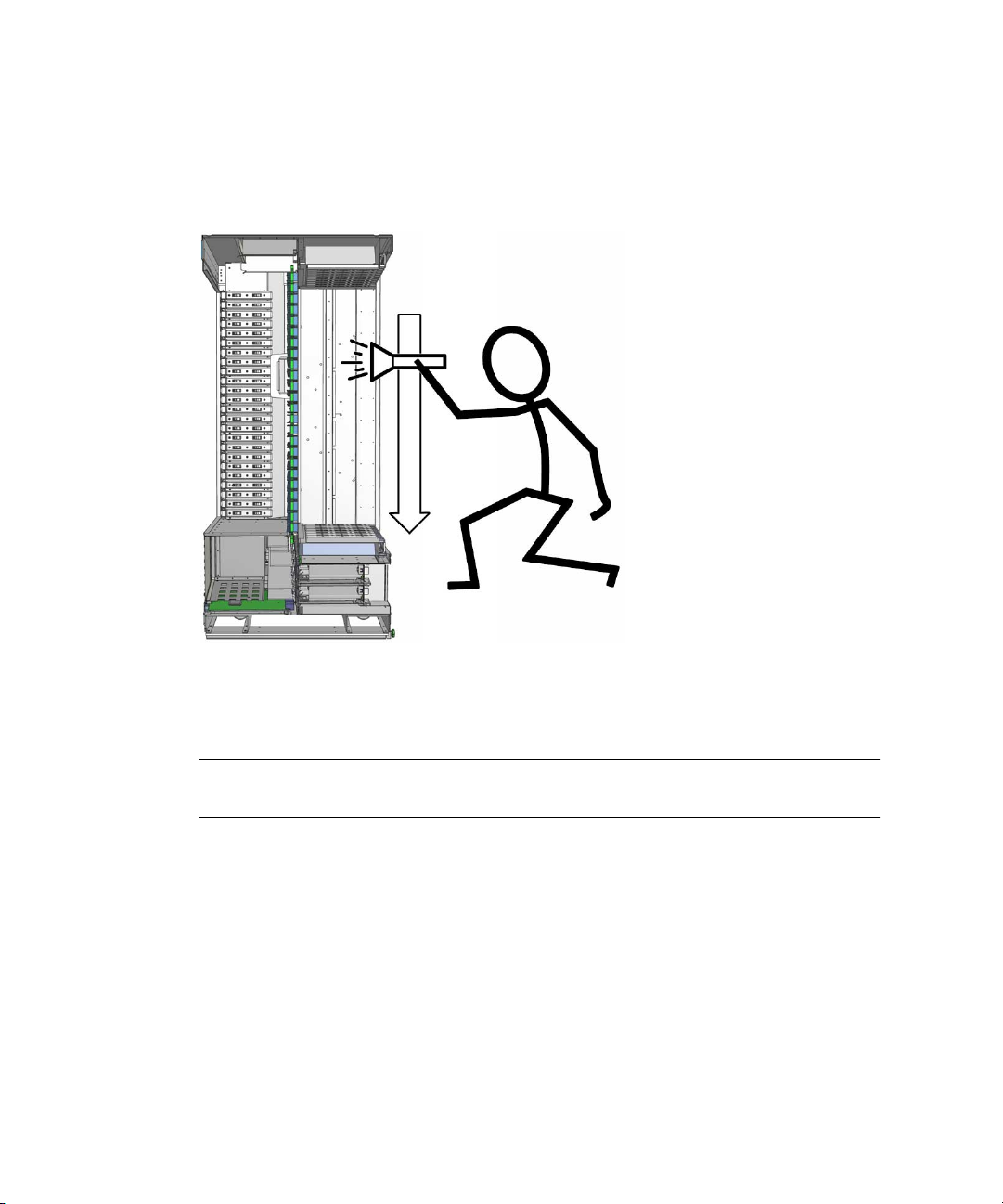
See
FIGURE 5-9.
Chapter 5 Unpacking the Chassis 31
Page 46

FIGURE 5-9 Rolling Out the Chassis
3. The pusher begins the rollout as the guiders steer the chassis.
Halfway off the pallet, the chassis might bottom out on the pallet edge because of
the antitilt bar. In this situation:
a. The pusher continues to push, flexing the pallet load surface with the
pusher’s weight.
b. The guiders move the chassis side-to-side in a concerted fashion.
Once the antitilt bar has cleared the pallet edge, the chassis will begin rolling
down the ramps under its own weight.
4. The pusher stops pushing and moves to the end of the ramps to assist the
guiders.
5. The guiders control the descent of the chassis down the ramps and onto the
floor.
Note – Though not recommended, rollout is possible with just two people. At Step
b, the guider must repeatedly switch sides until the chassis moves free. Additionally,
the pusher will take the side opposite the guider in Step 4.
6. (Optional) Reassemble the crate.
a. Remove the ramps from the side of the pallet.
32 Sun Datacenter Switch 3456 Installation Guide • December 2008
Page 47

b. Lay the ramps and their bolts onto the pallet.
c. Return the shells to the pallet and secure them together.
d. Set the sub-cap into the shells.
e. Set the cap onto the shells.
Chapter 5 Unpacking the Chassis 33
Page 48

34 Sun Datacenter Switch 3456 Installation Guide • December 2008
Page 49

Chapter 5 Unpacking the Chassis 35
Page 50

CHAPTER
6
Installing the Chassis
This chapter describes procedures for installing and inspecting the Sun Datacenter
Switch 3456 chassis. Topics include:
■ “Installing the Chassis” on page 35
■ “Inspecting the Chassis” on page 43
Installing the Chassis
This section describes getting the chassis to the final location.
▼ To Move to the Final Location
This procedure assumes that you have the final location ready for receiving the Sun
Datacenter Switch 3456 chassis, and that the chassis has been unpacked from the
shipping crate.
1. Walk the path to the final location.
■ Prop open any doors that must be passed.
■ Take preparatory steps if security must be overridden.
■ Post signs for directions and information for others not involved with the
movement.
■ Sweep the path and check the floor surfaces for objects that might hinder
movement, and remove those objects.
■ Check for folds or loose ends of carpeting (if traveling over carpeting).
■ Have metal sheets or masonite panels ready for thresholds, gaps, or carpeting.
■ Remove any obstructions from the path.
35
Page 51

■ Check the elevators in path, if any.
2. Verify that the leveling feet are in the fully raised position.
3. With one person as the pusher and at least one other person as a guider, begin
moving the chassis on the path.
Caution – The guider can cross to either side of the chassis, but should never
remain in the path of motion.
4. Move the chassis as slow as reasonably possible.
Note – When approaching intersections, doorways, or places where interaction with
others or collision might occur, announce your presence.
5. When you arrive at the final location, position the chassis for leveling and
securing.
▼ To Level the Chassis
Once the chassis is at the final location, you must level the chassis. The chassis does
not need to be perfectly level. However, the load borne by the casters should now be
distributed between the casters and the leveling feet.
Note – The directions indicated in this procedure are referenced from the front or
line card side of the chassis.
1. Position the Sun Datacenter Switch 3456 in the final location.
2. Using the adjustable wrench, lower the first leveling foot so that it contacts the
floor and you begin to feel resistance.
See FIGURE 6-1.
36 Sun Datacenter Switch 3456 Installation Guide • December 2008
Page 52

FIGURE 6-1 Lowering the Feet
3. Repeat Step 2 for each leveling foot.
4. Lower each foot two additional turns.
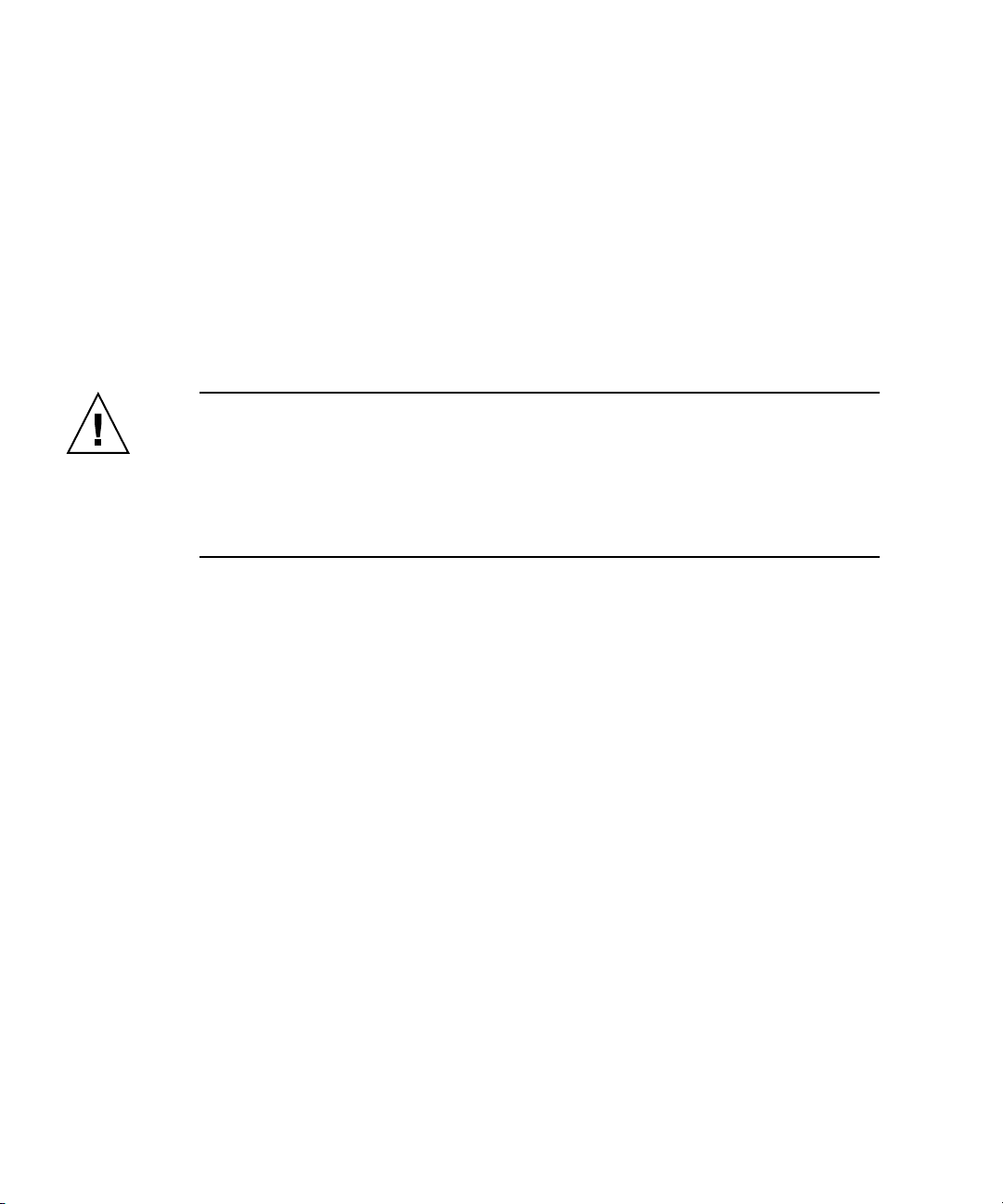
5. Place a beam level at the center of the chassis, running right to left.
See
FIGURE 6-2.
Chapter 6 Installing the Chassis 37
Page 53
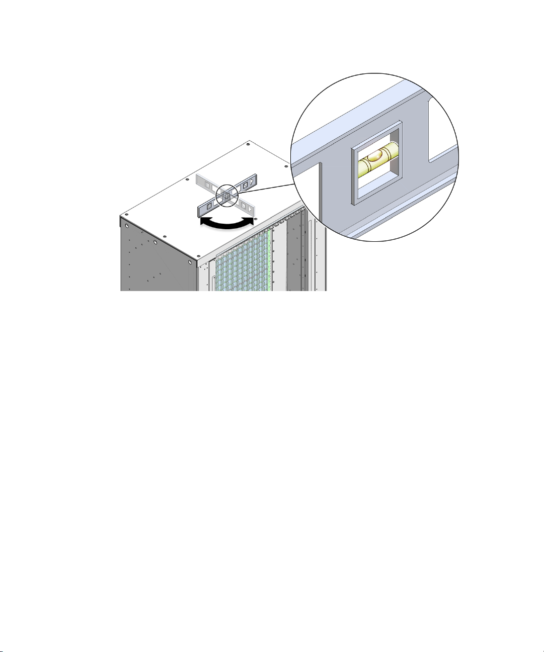
FIGURE 6-2 Setting the Level
6. Note the position of the bubble.
7. Rotate the beam level 90 degrees, now running front to rear.
See
FIGURE 6-2.
8. Note the position of the bubble.
9. Consider your next step:
■ If the bubble favored the right and the front, raise the right front foot or lower
the left rear foot.
■ If the bubble favored the right and the rear, raise the right rear foot or lower
the left front foot.
■ If the bubble favored the left and the front, raise the left front foot or lower the
right rear foot.
■ If the bubble favored the left and the rear, raise the left rear foot or lower the
right front foot.
10. Adjust the appropriate leveling foot.
11. Repeat Step 5 to Step 10 until the chassis is level.
■ If the adjustment causes a caster to lift from the floor, go to Step 12.
■ If the adjustment causes a foot to lift from the floor, go to .
■ Otherwise, go to Step 19.
38 Sun Datacenter Switch 3456 Installation Guide • December 2008
Page 54

12. Raise all feet equally by one quarter turn.
13. Repeat Step 12 until the caster seats.
14. If completing Step 13 makes the chassis unlevel, stop.
15. Go to Step 19.
16. Lower all feet equally by one quarter turn.
17. Repeat Step 16 until the foot seats.
18. If completing Step 17 makes the chassis unlevel, stop.
19. The present state is sufficient.
▼ To Secure the Chassis
Some building codes might require securing the Sun Datacenter Switch 3456 to its
final location. You can use the brackets removed when unpacking to help secure the
Sun Datacenter Switch 3456 to the floor.
1. Using an adjustable wrench, loosen the screws securing the corner brackets to
the chassis.
2. Using the brackets as a template, mark the floor for fastener locations.
3. Remove the corner brackets.
4. Prepare the floor as appropriate for building codes.
5. Reattach the corner brackets to the chassis.
6. Secure the brackets to the floor, using washers or shims where appropriate.
▼ To Remove the Power Supply Filler Panels
The Sun Datacenter Switch 3456 ships with power supply filler panels installed. If
power supplies are to be installed, the filler panels should be removed first.
1. Swing the release lever of the power supply filler panel out and to the right.
2. Pull the handle of the filler panel to remove it from the chassis.
3. Set the filler panel aside.
4. Repeat from Step 1 for all remaining filler panels.
Chapter 6 Installing the Chassis 39
Page 55

▼ To Remove the Line Card Filler Panels
Your Sun Datacenter Switch 3456 might ship with line card filler panels installed.
You must remove the filler panel where a line card will install.
1. Grasp the locking levers at each end of the filler panel.
See
FIGURE 6-3.
FIGURE 6-3 Turning Filler Panel Lock Levers
2. Turn the levers counter-clockwise to the unlocked position.
FIGURE 6-3.
See
3. Pull the filler panel away from the chassis by the handles.
See
FIGURE 6-4.
40 Sun Datacenter Switch 3456 Installation Guide • December 2008
Page 56
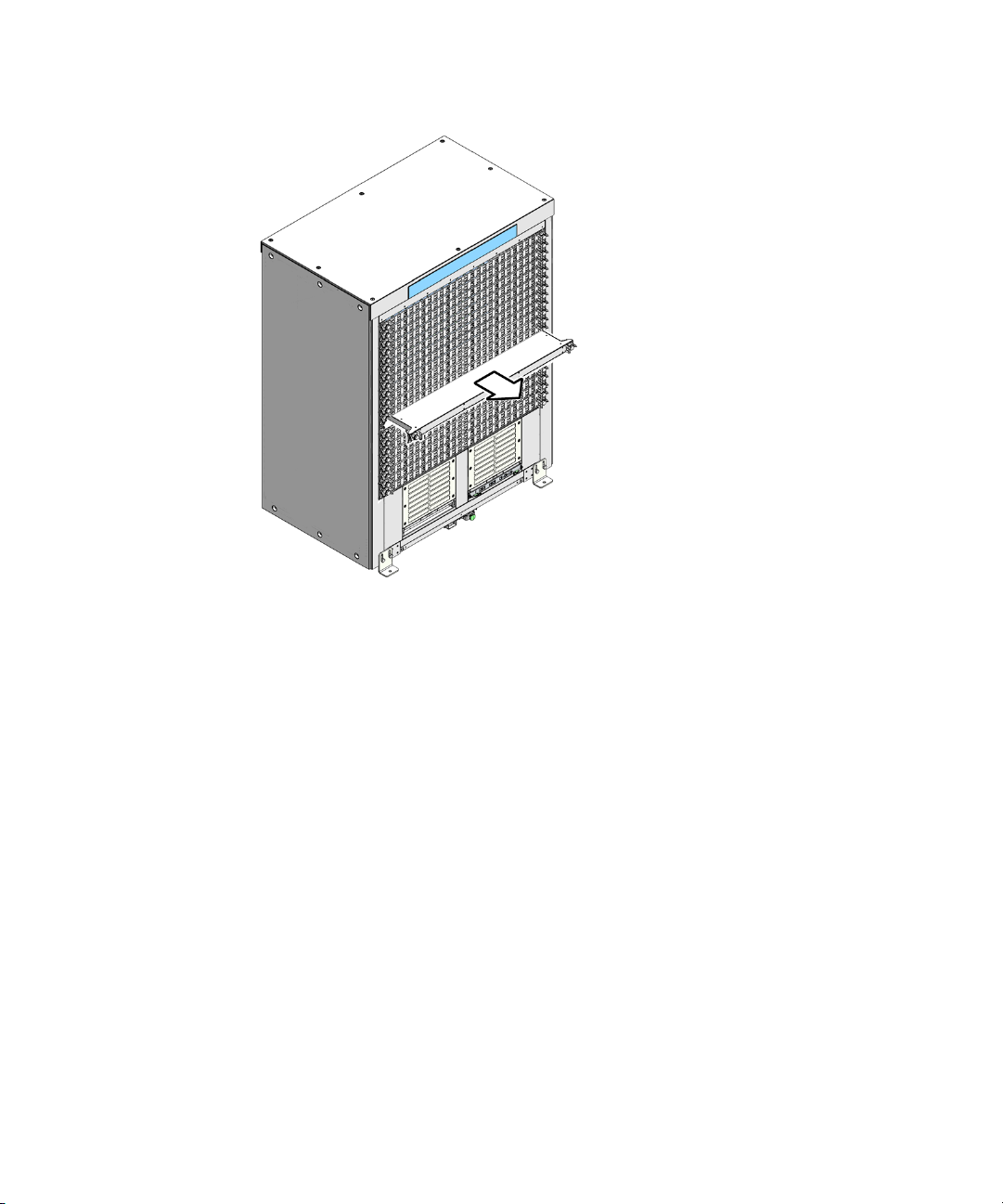
FIGURE 6-4 Removing the Filler Panel
4. Repeat from Step 1 for any other filler panels to be removed.
▼ To Install the Line Card Filler Panels
If the Sun Datacenter Switch 3456 is to be configured with less than 24 line cards, the
vacant slots must have filler panels installed to maintain proper airflow and thermal
management.
1. Grasp the handles at each end of the filler panel and lift the panel to the vacant
slot.
2. Slide the filler panel half-way into the chassis.
3. Turn the levers counter-clockwise to the unlocked position.
See
FIGURE 6-5.
Chapter 6 Installing the Chassis 41
Page 57
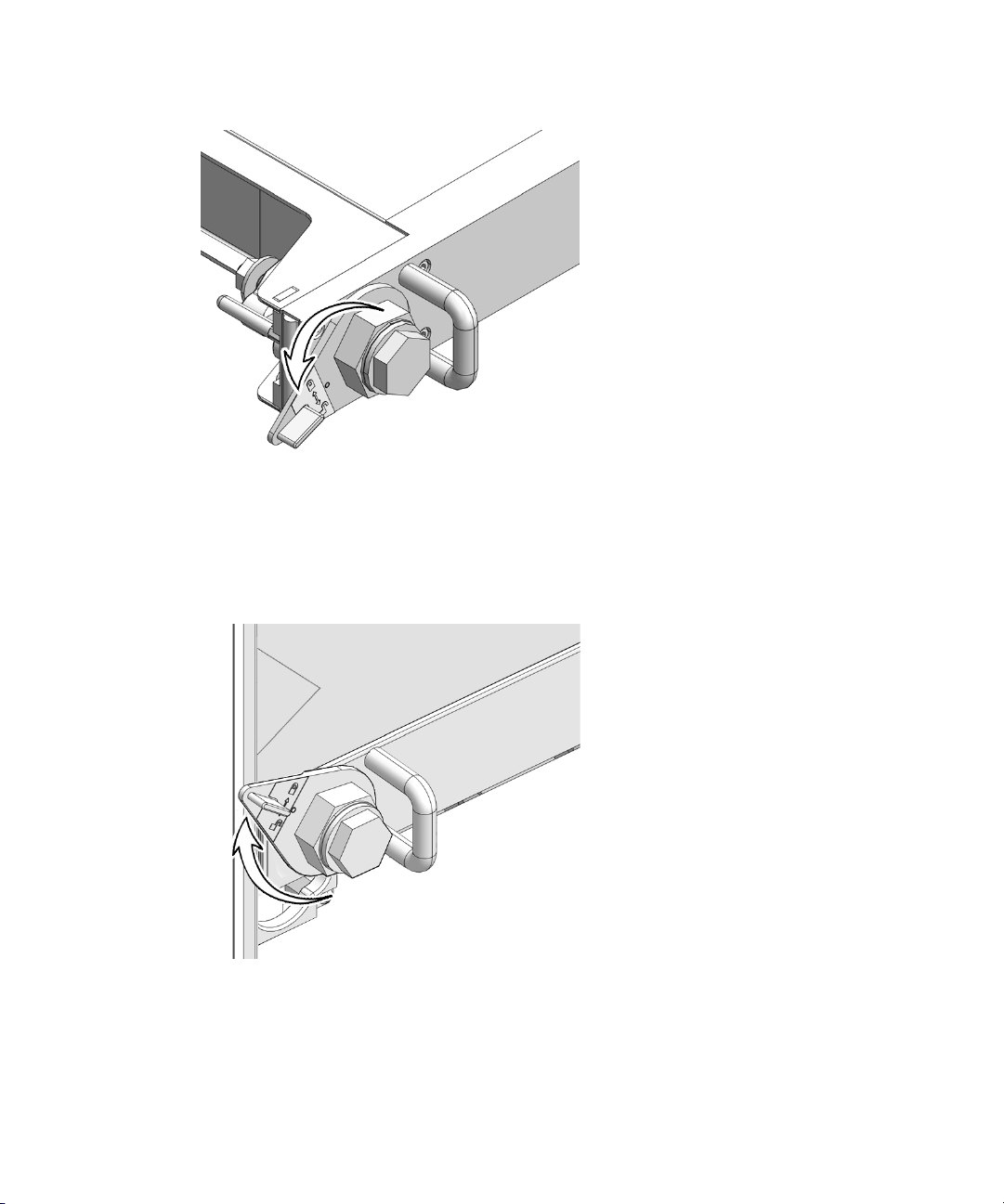
FIGURE 6-5 Turning Filler Panel Lock Levers Counter-Clockwise
4. Slide the filler panel into the chassis until it stops.
5. Turn the levers clockwise to the locked position.
See
FIGURE 6-6.
FIGURE 6-6 Turning Filler Panel Lock Levers Clockwise
6. Repeat from Step 1 for any remaining vacant slots.
42 Sun Datacenter Switch 3456 Installation Guide • December 2008
Page 58

Inspecting the Chassis
The weight of the Sun Datacenter Switch 3456 promotes a susceptibility to vibration
and movement. It is good practice to inspect the chassis as an early part of the
installation process.
▼ To Verify Electrical Leakage
Use a DMM for this verification test.
1. Grasp the release lever of power supply 0 and pull to release the power supply.
See
FIGURE 6-7.
FIGURE 6-7 Releasing the Power Supply
2. Continue to pull the power supply halfway out, but do not remove it.
3. Repeat from Step 1 for all power supplies.
4. Set the DMM for ohms.
If the DMM is not autoranging, set it for the highest resistance.
5. Touch the black probe of the DMM to the chassis ground.
See
FIGURE 6-8.
Chapter 6 Installing the Chassis 43
Page 59

FIGURE 6-8 Verifying Electrical Leakage
6. Touch the red probe to each one of the line card power connectors on the right
side.
The resistance should be no less than 1 megohm.
7. Move the black probe to a screw on the midplane stiffener.
See
FIGURE 6-8.
8. Repeat Step 6.
9. Move the black probe to a bus bar screw that is floating in the bus bar.
See
FIGURE 6-8.
10. Repeat Step 6.
11. Move the black probe to a line card power connector on the left side.
See
FIGURE 6-8.
12. Repeat Step 6.
13. If you read less than 1 megohm on any of these tests, investigate why.
14. Continue to “To Verify Electrical Continuity” on page 45.
▼ To Verify Electrical Continuity
Use a DMM for this verification test.
44 Sun Datacenter Switch 3456 Installation Guide • December 2008
Page 60

1. Set the DMM for ohms.
If the DMM is not autoranging, set it for the lowest resistance.
2. Touch the black probe of the DMM to the chassis ground.
FIGURE 6-9.
See
FIGURE 6-9 Verifying Electrical Continuity
3. Touch the red probe to each one of the line card power connectors on the left
side.
The resistance should be no greater than 50 ohm.
4. Move the black probe to a screw on the midplane stiffener.
See
FIGURE 6-9.
5. Repeat Step 3.
6. Move the black probe to a bus bar screw that is floating in the bus bar.
See
FIGURE 6-9.
7. Repeat Step 3.
8. Move the black probe to a line card power connector on the left side.
See
FIGURE 6-9.
9. Repeat Step 3.
10. If you read more than 50 ohm on any of these tests, investigate why.
Chapter 6 Installing the Chassis 45
Page 61

11. Slide power supply 0 back in its slot until the release lever begins to move.
FIGURE 6-10.
See
FIGURE 6-10 Securing the Power Supply
12. Swing the power supply release lever to the left to secure the power supply.
13. Repeat Step 11 for all power supplies.
46 Sun Datacenter Switch 3456 Installation Guide • December 2008
Page 62

CHAPTER
7
Inspecting and Repairing Pins
This chapter describes procedures to inspect and repair the midplane pins. Topics
include:
■ “Midplane Filler Strips” on page 47
■ “Inspecting Pins” on page 48
■ “Repairing and Replacing Pins” on page 54
Midplane Filler Strips
The Sun Datacenter Switch 3456 ships with plastic filler strips affixed to the
midplane. These strips protect the pins of the midplane connectors during the
installation process. The filler strips are secured in place by short pieces of rubber
tubing, which are inserted over the midplane alignment pins. See
FIGURE 7-1 Midplane Filler Strips
FIGURE 7-1.
47
Page 63

Inspecting Pins
Before installing the fabric cards and line cards, you must inspect the pins of the
midplane connectors. Inspection is a meticulous process, and cannot be hurried.
Expect about 30 minutes for each side of the midplane. To shorten this time, one
person might inspect the pins on the fabric card side (rear) of the midplane, while
another inspects the pins on the line card side (front) of the midplane.
Tools
For inspection, you need the following tools:
■ Pin gauge block
■ Bright flashlight
■ Magnifying glass or loupe
■ Notepad and pen
▼ To Inspect the Pins on the Rear Side of the Midplane
The primary tool used to check the midplane pins is the pin gauge block. This tool
effortlessly slides over the straight pins of an iTRAC connector that is in good
condition. If there is any resistance, a pin is bent and requires further examination.
1. Remove the rubber tubes that secure the filler strip for fabric card slot 0.
Set the tubes aside.
2. Remove the filler strip for slot 0.
Set the filler strip aside.
3. Using the pin gauge block, gently insert it into the iTRAC connector at the top.
4. If you feel any resistance to insertion, note the connector number on the
notepad.
See
FIGURE 7-2.
48 Sun Datacenter Switch 3456 Installation Guide • December 2008
Page 64

FIGURE 7-2 Fabric Card Connector Nomenclature
The connector number is located above each connector and is unique. For
example, the upper-left connector number is FC-R23-F0. The lower-right
connector number is FC-R0-F17. The connector number is decoded as follows:
■ FC – Fabric card.
■ Ra – Row a, where a is 0 through 23.
■ Fb – Frame b, where b is 0 through 17.
The origin of this coordinate system is the lower-left corner, FC-R0-F0. In
FIGURE 7-2, the connector identified is FC-R13-F15.
5. Continue down to the next connector and repeat from Step 3.
6. After you have checked the bottom connector, visually inspect any connectors
you noted previously.
Chapter 7 Inspecting and Repairing Pins 49
Page 65
7. Using the magnifying glass and the flashlight positioned above you, look at the
pins of the connector.
Look at the pins straight on. See
FIGURE 7-3 Inspecting the Pins (Fabric Card)
FIGURE 7-3.
8. Look for any light reflection inconsistencies.
A bent pin reflects light differently, either brighter or darker than the surrounding
pins.
Note – Do not look at the individual pins, rather look at all of the connector ’s pins
as a whole. A bent pin will be apparent.
9. Identify the pin that needs repair or replacement and note this.
10. Look for any contaminants that might be present.
These contaminants might appear as light dots near the pins.
11. Move your head to the next suspect connector and inspect its pins, repeating
Step 7 through Step 10.
12. Continue in this manner for all suspect connectors.
13. Repeat Step 1 to Step 12 for fabric card slot 1 to fabric card slot 17.
50 Sun Datacenter Switch 3456 Installation Guide • December 2008
Page 66

14. If a pin needs repair or replacement, see “Repairing and Replacing Pins” on
page 54.
▼ To Inspect the Pins on the Front Side of the Midplane
The primary tool used to check the midplane pins is the pin gauge block. This tool
effortlessly slides over the straight pins of an iTRAC connector that is in good
condition. If there is any resistance, a pin is bent and requires further examination.
1. Remove the rubber tubes that secure the filler strip for line card slot 0.
Set the tubes aside.
2. Remove the filler strip for slot 0.
Set the filler strip aside.
3. Using the pin gauge block, gently insert it into the iTRAC connector on the left
side.
4. If you feel any resistance to insertion, note the connector number on the
notepad.
See
FIGURE 7-4.
Chapter 7 Inspecting and Repairing Pins 51
Page 67

FIGURE 7-4 Line Card Connector Nomenclature
The connector number is located above each connector and is unique. For
example, the lower-left connector number is LC-C17-L0. The upper-right
connector number is LC-C0-L23. The connector number is decoded as follows:
■ LC – Line card.
■ Cc – Column c , where c is 0 through 17.
■ Ld – Level d , where d is 0 through 23.
The origin of this coordinate system is the lower right corner, LC-C0-L0. In
FIGURE 7-4, the connector identified is LC-C14-L10.
5. Continue right to the next connector and repeat from Step 3.
6. After you have checked the far right connector, visually inspect any connectors
you noted previously.
52 Sun Datacenter Switch 3456 Installation Guide • December 2008
Page 68

7. Using the magnifying glass and the flashlight positioned above you, look at the
pins of the connector.
Look at the pins as straight on. See
FIGURE 7-5 Inspecting the Pins (Line Card)
FIGURE 7-5.
8. Look for any light reflection inconsistencies.
A bent pin reflects light differently, either brighter or darker than the surrounding
pins.
Note – Do not look at the individual pins, rather look at all of the connector ’s pins
as a whole. A bent pin will be apparent.
9. Identify the pin that needs repair or replacement and note this.
10. Look for any contaminants that might be present.
These contaminants might appear as light dots near the pins.
11. Move your head to the next suspect connector and inspect its pins, repeating
Step 7 through Step 10.
12. Continue in this manner for all suspect connectors.
13. Repeat Step 1 to Step 12 for line card slot 1 to line card slot 23.
14. If a pin needs repair or replacement, see “Repairing and Replacing Pins” on
page 54.
Chapter 7 Inspecting and Repairing Pins 53
Page 69

Repairing and Replacing Pins
If you find a bent pin, it might be possible to straighten it. If the bend is too severe,
the pin must be replaced.
Tools
To repair or replace a pin, you need the following tools:
■ Molex pin replacement tool
■ Replacement pins (extracted from a spare iTRAC connector)
■ Head-mounted magnifier
■ Flashlight
Another person to assist you can make the task much easier.
▼ To Remove Pins
Before you can attempt to straighten a bent pin, you must remove the pins
surrounding the bent pin. See
1. Locate the bent pin.
See
FIGURE 7-6.
FIGURE 7-6.
54 Sun Datacenter Switch 3456 Installation Guide • December 2008
Page 70

FIGURE 7-6 Locating the Bent Pin and Surrounding Pins
2. Use the Molex tool to remove the pin (if any) above the bent pin.
a. Slide the Molex tool completely over the pin.
b. Activate the lock to grasp the pin.
c. Press the trigger to pull the pin out.
d. Push the ejector back in to release the pin and reset the tool.
3. Set the pin aside.
4. Use the Molex tool repeating Step 2 to remove the pin (if any) below the bent
pin.
5. Set the pin aside.
6. Repeat Step 2 to remove the pins to the left and right sides of the bent pin (if
any).
7. Set these pins aside.
The bent pin is now exposed.
Chapter 7 Inspecting and Repairing Pins 55
Page 71
8. Flip the Molex tool over and use the tube in attempt to straighten the pin.
If the pin cannot be straightened satisfactorily, or might break if straightened,
replace it.
9. Remove the pin following Step 2.
10. If the pin is too bent for the Molex tool, see “To Remove a Pin With
Needle-Nose Pliers” on page 56.
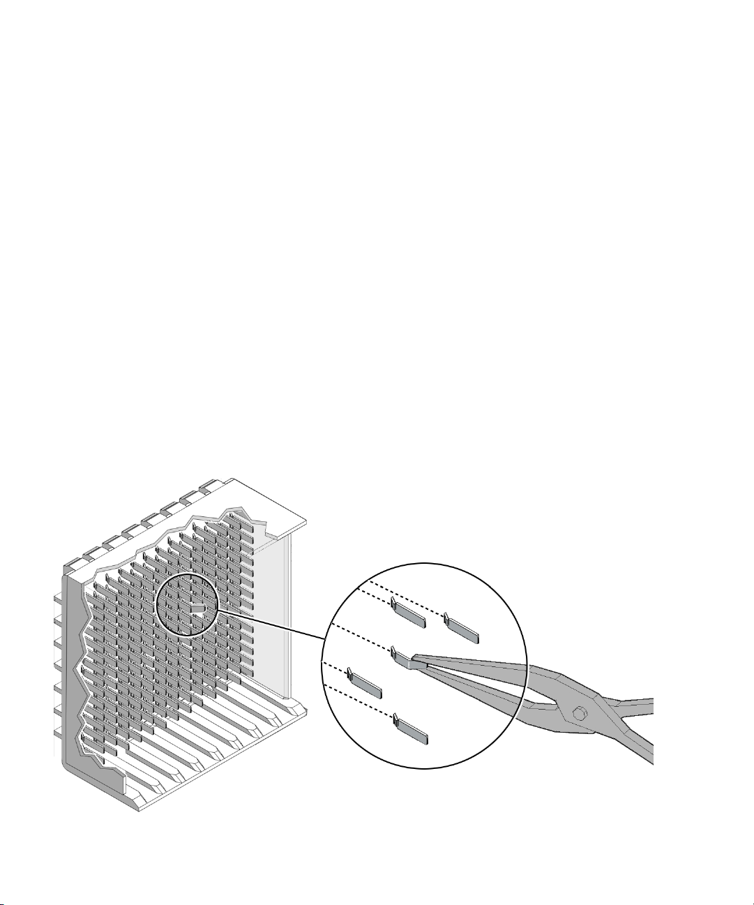
▼ To Remove a Pin With Needle-Nose Pliers
Perform this procedure only when the Molex tool is incapable of removing the pin.
You need micro-tipped needle-nose pliers.
1. With one hand, grasp the pin with the very tip of the needle-nose pliers.
2. Squeeze the pliers sufficiently to grip the pin for extraction.
3. With the other hand, steady the pliers in a position for perpendicular
extraction.
See
FIGURE 7-7.
FIGURE 7-7 Using Pliers to Pull a Pin
56 Sun Datacenter Switch 3456 Installation Guide • December 2008
Page 72

4. In one motion, use both hands to pull the pin out of the connector.
5. Dispose of the pin.
▼ To Insert Pins
When inserting pins, work from the top down. Repeat Step 1 through Step 5 for each
pin that needs to be inserted.
1. Ready the Molex tool for a pin insertion.
a. Press the trigger on the Molex tool to release the ejector.
b. Slide a pin into the opening.
A portion of the pin protrudes.
c. Activate the lock to grasp the pin.
2. Position the Molex tool over the hole in the connector where you want to insert
the pin.
3. Holding the Molex tool perpendicular to the plane of the connector, insert the
pin into the connector.
4. Slowly press the ejector in until it stops.
The pin is inserted.
5. Carefully deactivate the lock and withdraw the Molex tool from the connector.
Chapter 7 Inspecting and Repairing Pins 57
Page 73

58 Sun Datacenter Switch 3456 Installation Guide • December 2008
Page 74

CHAPTER
8
Installing Fabric Cards
This chapter describes inspection and installation procedures, and administrative
commands for fabric cards. Topics include:
■ “Inspecting Fabric Cards” on page 60
■ “Installing Fabric Cards Into the Chassis” on page 63
■ “Fabric Card Administrative Commands” on page 68
Fabric Card Considerations
Caution – The thermal management of the switch chassis is compromised when a
fabric card slot is vacant. You must install a filler panel or replacement fabric card
immediately after removing one.
Though the fabric cards are not heavy, they should be installed by two people. This
method ensures that proper alignment can be achieved before the fabric card
retainers are locked. Improper alignment can bend midplane connector pins.
Fabric cards use high-density iTRAC connectors that interface with the midplane
pins. If these connectors are damaged, the pins of the midplane connector can also
be damaged upon fabric card insertion.
You must inspect the fabric card connectors, fans, and retainers before installing the
fabric card into the switch chassis.
59
Page 75

Inspecting Fabric Cards
Inspect the fabric cards to see if they are ready for installation.
▼ To Inspect the Fabric Card iTRAC Connectors
The iTRAC connectors on fabric cards are the receptacles for the midplane connector
pins. These connectors are checked just as meticulously as the midplane connector
pins. However, you must verify that no connectors are damaged and no holes are
blocked.
You need the following tools:
■ Bright flashlight
■ Magnifying glass or loupe
■ Dental type metal pick
1. Unwrap the fabric card from its antistatic packaging.
2. Place the fabric card on a work surface with the iTRAC connectors facing you.
3. Using the flashlight positioned to the side and above you, look at the holes of
the left-end connector.
Look at the holes straight on. See
FIGURE 8-1.
FIGURE 8-1 Inspecting Fabric Card Connectors
60 Sun Datacenter Switch 3456 Installation Guide • December 2008
Page 76

Note – Do not look at the individual holes, rather look at all of the connector ’s holes
as a group. A damaged or contaminated hole will be apparent.
4. Look for any closed over or contaminated holes.
A closed-over or contaminated hole appears brighter than the surrounding holes.
If you see any closed-over or contaminated holes, use the magnifying glass and
pick to remove the contamination or open the closed-over hole.
Verify that the contamination has been removed from the connector and the
connector surface is clean. Use a spare midplane connector pin to verify the
resistance to insertion.
■ If there is great resistance, but the pin does enter the hole properly, investigate
why.
■ If the pin does not enter the hole at all, reject the fabric card. Contact your
SunService
SM
representative.
5. Look for any enlarged or cracked holes.
An enlarged or cracked hole appears darker than the surrounding holes.
If you see any enlarged or cracked holes, use a spare midplane connector pin to
verify the resistance to insertion.
■ If the insertion gives a little resistance and the pin does not wobble in the hole,
the connector is still acceptable.
■ If there is no resistance to insertion and the pin can wobble in the hole, reject
the fabric card. Contact your SunService representative.
6. Move your head slightly right to the next connector, and inspect its pins,
repeating Step 4 and Step 5.
7. Continue in this manner for each connector until you reach the right side of the
fabric card.
▼ To Inspect the Fans
The fans of the fabric card are FRU components. The fans secure in position with
two thumbscrews.
1. Ensure that each fan is seated properly in the fabric card.
2. Ensure that both thumbscrews are tight on each fan.
Chapter 8 Installing Fabric Cards 61
Page 77

▼ To Inspect the Retainers
The two retainers on the fabric card serve three purposes:
■ Align the fabric card for proper insertion into the chassis.
■ Allow final insertion of the fabric card into the chassis and simplify the physical
connection of the fabric card connectors to the midplane connectors.
■ Allow extraction of the fabric card from the chassis and simplify the physical
disconnection of the fabric card connectors from the midplane connectors.
The retainer’s design is shown in
● Ensure that the pieces of the retainer look finished, move smoothly, do not
FIGURE 8-2.
bind, or do not feel loose or sloppy in any way.
See
FIGURE 8-2.
FIGURE 8-2 Retainer Design
62 Sun Datacenter Switch 3456 Installation Guide • December 2008
Page 78

Installing Fabric Cards Into the Chassis
▼ To Install the Midplane Stiffener
Note – The midplane stiffener must be installed before the fabric cards are installed.
Installing the midplane stiffener is a two-person task, as both people must work in a
synchronized manner. To prevent damage to the pins of the midplane connector, the
two installers must carefully align the stiffener with the midplane crossbar.
1. Place the stiffener on a work surface, with the retainers facing the two
installers.
2. Using a 17 mm socket and ratchet, turn each retainer drive screw fully
counter-clockwise until resistance is felt.
3. Rotate both the retainer drive screws clockwise, 1/4 turn.
4. Lift the midplane stiffener from the work surface and insert the stiffener into
the chassis at slot 11.
Ensure that the stiffener is perpendicular to the surface of the midplane. See
FIGURE 8-3.
Chapter 8 Installing Fabric Cards 63
Page 79

FIGURE 8-3 Installing Midplane Stiffener
5. Continue to slide the midplane stiffener in, maintaining a perpendicular
orientation.
When the midplane stiffener has almost seated, stop.
6. Rotate both retainer levers to the unlocked position.
7. Verify that the end of the midplane stiffener properly contacts the midplane
crossbar.
8. Have your assistant press the midplane stiffener into position.
9. Rotate both retainer levers to the locked position.
10. Slowly rotate each retainer drive screw clockwise, until resistance is felt, then
stop.
11. Simultaneously rotate the retainer drive screws clockwise, stopping at each half
turn, to maintain synchronization.
During this time, the levers might have moved from the locked position. Move
the levers back to the locked position and continue.
12. Continue synchronized rotation until great resistance is felt, then stop.
13. Verify that the midplane stiffener is properly seated against the midplane
crossbar.
64 Sun Datacenter Switch 3456 Installation Guide • December 2008
Page 80

▼ To Install the Fabric Cards
Installing the fabric card is a two-person task, as both people must work in a
synchronized manner. To prevent damage to the fabric cards or the pins of the
midplane connector, the two installers perform identical tasks simultaneously.
1. Install the midplane stiffener.
See “To Install the Midplane Stiffener” on page 63.
2. Extend the antitilt bar from the bottom of the switch chassis.
See
FIGURE 8-4.
FIGURE 8-4 Extending the Antitilt Bars
3. Place a fabric card on a work surface, with the retainers facing the two
installers.
4. Using a 17 mm socket and ratchet, turn each retainer drive screw fully
counter-clockwise until resistance is felt.
5. Rotate both the retainer drive screws clockwise, 1/4 turn.
6. Lift the fabric card from the work surface and orient it vertically, with the
status LEDs at the bottom.
Chapter 8 Installing Fabric Cards 65
Page 81

7. Insert the fabric card into the chassis at slot 7.
Ensure that the fabric card is vertical.
Note – Once the fabric card is about halfway into the slot, the installers no longer
have to bear the weight of the fabric card.
8. Continue to slide the fabric card in, maintaining a vertical orientation.
When you feel resistance, stop.
9. Rotate both retainer levers to the unlocked position.
10. Slide the fabric card for another 1.75 in (4 cm) until it stops.
11. Rotate both retainer levers to the locked position.
12. Slowly rotate each retainer drive screw clockwise, until resistance is felt, then
stop.
13. Simultaneously rotate the retainer drive screws clockwise, stopping at each half
turn, to maintain synchronization.
During this time, the levers might have moved from the locked position. Move
the levers back to the locked position and continue.
14. Continue synchronized rotation until great resistance is felt, then stop.
15. Verify that the fabric card is properly seated in the slot.
16. Give each retainer drive screw a final turn to torque.
17. Repeat Step 3 through Step 16 for each fabric card, installing the cards into the
following slots in the given sequence:
10, 4, 13, 1, 16, 8, 11, 5, 14, 2, 17, 6, 9, 3, 12, 0, 15
18. Retract and secure the antitilt bar.
19. Remove the midplane stiffener.
See “To Remove the Midplane Stiffener” on page 66.
▼ To Remove the Midplane Stiffener
The midplane stiffener must be removed before installing the line cards.
1. Using a 17 mm socket and ratchet, turn each retainer drive screw
counter-clockwise until no resistance is felt.
66 Sun Datacenter Switch 3456 Installation Guide • December 2008
Page 82
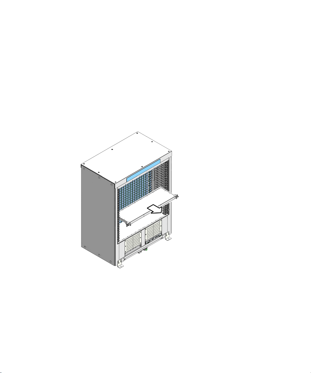
2. Slowly rotate each retainer drive screw counter-clockwise, until resistance is
felt, then stop.
3. Simultaneously rotate the retainer drive screws clockwise, stopping at each half
turn, to maintain synchronization.
4. Continue synchronized rotation until greater resistance is felt, then stop.
5. Rotate both retainer levers to the unlocked position.
6. Grasp the handles at both ends of the midplane stiffener and slowly pull it
from the chassis.
See
FIGURE 8-5.
FIGURE 8-5 Removing the Midplane Stiffener
7. Set the midplane stiffener aside.
Chapter 8 Installing Fabric Cards 67
Page 83
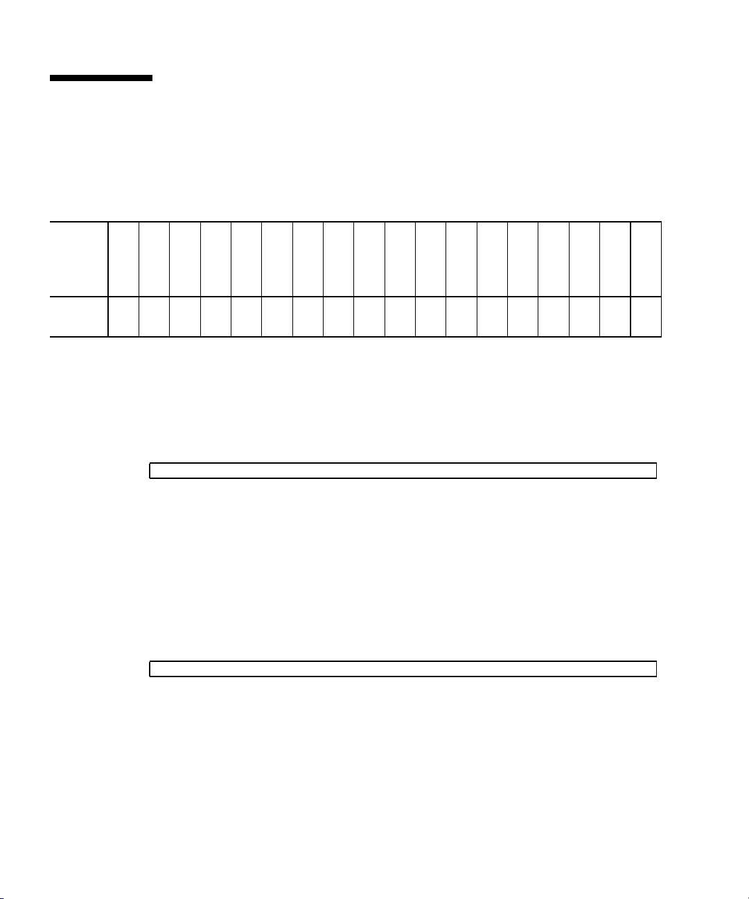
Fabric Card Administrative Commands
This section provides basic commands to administrate fabric cards when they are
first installed. Some commands require you to reference
TABLE 8-1 Fabric Card Slot Mapping
TABLE 8-1.
Fabric
card
Slot
number
IPMB
address
FC0FC1FC2FC3FC4FC5FC6FC7FC8FC9FC10FC11FC12FC13FC14FC15FC16FC
17
01234567891011121314151617
b2 b4 b6 b8 ba bc be c0 c2 c4 c6 c8 ca cc ce d0 d2 d4
▼ To Enable Fabric Cards
● To enable standby power and the IPMB buses for a fabric card, type this
command:
# enableboard fc slot
where slot is the slot number of the fabric card from
When a fabric card is enabled, the Standby LED on that fabric card flashes.
TABLE 8-1.
▼ To Disable Fabric Cards
● To disable standby power and IPMB buses for a fabric card, type this
command:
# disableboard fc slot
where slot is the slot number of the fabric card from
When a fabric card is disabled, the Standby LED on that fabric card goes out.
68 Sun Datacenter Switch 3456 Installation Guide • December 2008
TABLE 8-1.
Page 84

▼ To Enable Fabric Card IPMB Buses
● To enable an IPMB bus on a fabric card, type this command:
# enableipmb fc slot bus
where:
■ slot is the slot number of the fabric card from TABLE 8-1
■ bus is either a or b
▼ To Disable Fabric Card IPMB Buses
● To disable an IPMB bus on a fabric card, type this command:
# disableipmb fc slot bus
where:
■ slot is the slot number of the fabric card from TABLE 8-1
■ bus is either a or b
▼ To Enable Fabric Card Standby Power
● To enable standby power on a fabric card, type this command:
# enablestby fc slot
where slot is the slot number of the fabric card from
TABLE 8-1.
▼ To Disable Fabric Card Standby Power
● To disable standby power on a fabric card, type this command:
# disablestby fc slot
where slot is the slot number of the fabric card from
TABLE 8-1.
Chapter 8 Installing Fabric Cards 69
Page 85
▼ To Fully Power On Fabric Cards
● To bring a fabric card to full power, type this command:
# activate fc slot
where slot is the slot number of the fabric card from
When a fabric card is activated, the OK LED is illuminated and the fabric card
goes to full power.
TABLE 8-1.
▼ To Power Down Fabric Cards to a Standby State
● To power down a fabric card to a standby state, type this command:
# deactivate fc slot
where slot is the slot number of the fabric card from
When a fabric card is deactivated, the OK LED turns off, but the Standby LED
remains flashing.
TABLE 8-1.
▼ To Read Fabric Card FRUID Information
● To read the FRUID information of a fabric card, type this command:
# clia fruinfo ipmb-address 0
where ipmb-address is the IPMB address of the fabric card from
The following sample is a portion of the output for fabric card 3:
TABLE 8-1.
# clia fruinfo b8 0
Pigeon Point Shelf Manager Command Line Interpreter
b8: FRU # 0, FRU Info
Common Header: Format Version = 1
Board Info Area:
Version = 1
Language Code = 25
Mfg Date/Time = May 28 15:08:00 2008 (6525548 minutes since 1996)
Board Manufacturer = Sun Microsystems, Inc.
Board Product Name = DCS 3456 - Fabric Card
Board Serial Number = 37535620821BT00030
Board Part Number = 375-3562-02
70 Sun Datacenter Switch 3456 Installation Guide • December 2008
Page 86

FRU Programmer File ID = Fruid_FC.txt
Product Info Area:
Version = 1
Language Code = 25
Manufacturer Name = Sun Microsystems, Inc.
Product Name = DCS 3456 - Fabric Card
Product Part / Model# = 375-3562-02
Product Version = Rev 3.4
Product Serial Number = 37535620821BT00030
Asset Tag
FRU Programmer File ID = Fruid_FC.txt
Chapter 8 Installing Fabric Cards 71
Page 87

72 Sun Datacenter Switch 3456 Installation Guide • December 2008
Page 88
CHAPTER
9
Installing Line Cards
This chapter describes inspection and installation procedures, and administrative
commands for line cards. Topics include:
■ “Inspecting Line Cards” on page 74
■ “Installing Line Cards Into the Chassis” on page 77
■ “Line Card Administrative Commands” on page 78
Line Card Considerations
Caution – The thermal management of the switch chassis is compromised when a
line card slot is vacant. You must install a filler panel or replacement line card
immediately after removing one.
Line cards are heavy and must be installed by two people. This method ensures that
proper alignment can be achieved before the line card retainers are locked. Improper
alignment can bend midplane connector pins.
Line cards use high-density iTRAC connectors that interface with the midplane pins.
If these connectors are damaged, the pins of the midplane connector can also be
damaged upon line card insertion.
Equally important, the line cards have iPASS connectors for attaching IB cables. If
one of these connectors is damaged, then 3 nodes of the line card cannot be used.
You must inspect the front and back line card connectors, and retainers before
installing the line card into the switch chassis.
73
Page 89
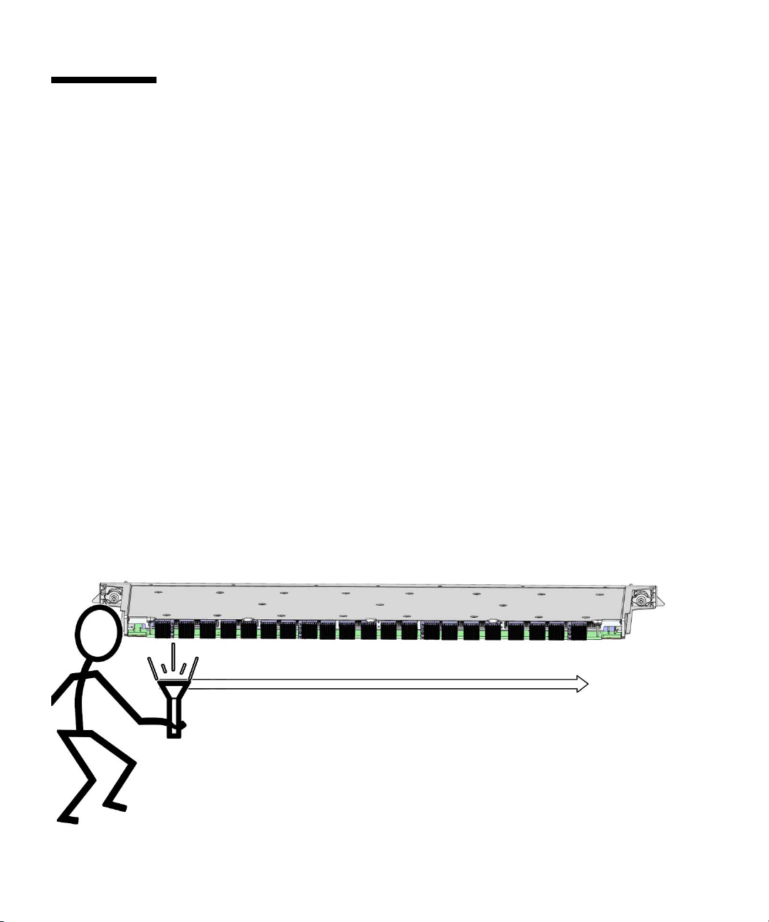
Inspecting Line Cards
Inspect the line cards that they are ready for installation.
▼ To Inspect the Line Card iTRAC Connectors
The large iTRAC connectors on line cards are the receptacles for the midplane
connector pins. These connectors are checked just as meticulously as the midplane
connector pins. However, you must verify that no connectors are damaged and no
holes are blocked.
You need the following tools:
■ Bright flashlight
■ Magnifying glass or loupe
■ Dental type metal pick
1. Unwrap the line card from its antistatic packaging.
2. Place the line card on a work surface with the iTRAC connectors facing you.
3. Using the flashlight positioned to the side and above you, look at the holes of
the left-end connector.
Look at the holes straight on. See
FIGURE 9-1.
FIGURE 9-1 Inspecting Line Card Connectors
74 Sun Datacenter Switch 3456 Installation Guide • December 2008
Page 90

Note – Do not look at the individual holes, rather look at all of the connector ’s holes
as a group. A damaged or contaminated hole will be apparent.
4. Look for any closed over or contaminated holes.
A closed-over or contaminated hole appears brighter than the surrounding holes.
If you see any closed-over or contaminated holes, use the magnifying glass and
pick to remove the contamination or open the closed-over hole.
Verify that the contamination has been removed from the connector and the
connector surface is clean. Use a spare midplane connector pin to verify the
resistance to insertion.
■ If there is great resistance, but the pin does enter the hole properly, investigate
why.
■ If the pin does not enter the hole at all, reject the line card. Contact your
SunService
SM
representative.
5. Look for any enlarged or cracked holes.
An enlarged or cracked hole appears darker than the surrounding holes.
If you see any enlarged or cracked holes, use a spare midplane connector pin to
verify the resistance to insertion.
■ If the insertion gives a little resistance and the pin does not wobble in the hole,
the connector is still acceptable.
■ If there is no resistance to insertion and the pin can wobble in the hole, reject
the fabric card. Contact your SunService representative.
6. Move your head slightly right to the next connector, and inspect its pins,
repeating Step 4 and Step 5.
7. Continue in this manner for each connector until you reach the right side of the
line card.
▼ To Inspect the iPASS Connectors
The small iPASS connectors on the line card are for the InfiniBand cables. The design
of these connectors is much simpler and more robust, so inspection is much easier.
● Check the small connectors for any debris, or cracked or bent fittings.
Most debris can be blown out. If you find a cracked or bent connector, contact
your Sun Service representative.
Chapter 9 Installing Line Cards 75
Page 91

▼ To Inspect the Retainers
The two retainers on the line card serve three purposes:
■ Align the line card for proper insertion into the chassis.
■ Allow final insertion of the line card into the chassis and simplify the physical
connection of the line card connectors to the midplane connectors.
■ Allow extraction of the line card from the chassis and simplify the physical
disconnection of the line card connectors from the midplane connectors.
The retainer’s design is shown in
● Ensure that the pieces of the retainer look finished, move smoothly, do not
FIGURE 9-2.
bind, or do not feel loose or sloppy in any way.
See
FIGURE 9-2.
FIGURE 9-2 Retainer Design
76 Sun Datacenter Switch 3456 Installation Guide • December 2008
Page 92

Installing Line Cards Into the Chassis
▼ To Install the Line Cards
Installing the line card is a two-person task, as both people must work in a
synchronized manner. To prevent damage to the line cards or the pins of the
midplane connector, the two installers perform identical tasks simultaneously.
1. Extend the antitilt bar from the bottom of the switch chassis.
2. Place a line card on a work surface, with the retainers facing the two installers.
3. Using a 17 mm socket and ratchet, turn each retainer drive screw fully
counter-clockwise until resistance is felt.
4. Rotate both the retainer drive screws clockwise, 1/4 turn.
5. Lift the line card from the work surface and orient it horizontally, with the link
status LEDs across the bottom.
6. Insert the line card into the chassis at slot 11.
Ensure that the line card is perpendicular to the surface of the midplane.
Note – Once the line card is about halfway into the slot, the installers no longer
have to bear the weight of the line card.
7. Continue to slide the line card in, maintaining a perpendicular orientation.
When you feel resistance, stop.
8. Rotate both retainer levers to the unlocked position.
9. Slide the line card for another 1.75 in (4 cm) until it stops.
10. Rotate both retainer levers to the locked position.
11. Slowly rotate each retainer drive screw clockwise, until resistance is felt, then
stop.
12. Simultaneously rotate the retainer drive screws clockwise, stopping at each half
turn, to maintain synchronization.
During this time, the levers might have moved from the locked position. Move
the levers back to the locked position and continue.
Chapter 9 Installing Line Cards 77
Page 93

13. Continue synchronized rotation until great resistance is felt, then stop.
14. Verify that the line card is properly seated in the slot.
15. Give each retainer drive screw a final turn to torque.
16. Repeat Step 2 through Step 15 for each line card, installing the cards into slots
12, 10, 13, and so on as described in “Component Distribution” on page 9.
17. Retract and secure the antitilt bar.
Line Card Administrative Commands
This section provides basic commands to administrate line cards when they are first
installed. Some commands require you to reference
TABLE 9-1 Line Card Slot Mapping
TABLE 9-1.
Line
card
Slot
number
IPMB
Address
Line
card
Slot
Number
IPMB
Address
Line
card
Slot
number
IPMB
Address
Line
card
Slot
number
IPMB
Address
LC5 5 8c LC11 11 98 LC17 17 a4 LC23 23 b0
LC4 4 8a LC10 10 96 LC16 16 a2 LC22 22 ae
LC3 3 88 LC9 9 94 LC15 15 a0 LC21 21 ac
LC2 2 86 LC8 8 92 LC14 14 9e LC20 20 aa
LC1 1 84 LC7 7 90 LC13 13 9c LC19 19 a8
LC0 0 82 LC6 6 8e LC12 12 9a LC18 18 a6
▼ To Enable Line Cards
● To enable standby power and the IPMB buses for a line card, type this
command:
# enableboard lc slot
where slot is the slot number of the line card from
When a line card is enabled, the Standby LED on that line card flashes.
TABLE 9-1.
78 Sun Datacenter Switch 3456 Installation Guide • December 2008
Page 94

▼ To Disable Line Cards
● To disable standby power and IPMB buses for a line card, type this command:
# disableboard lc slot
where slot is the slot number of the line card from
TABLE 9-1.
When a line card is disabled, the Standby LED on that line card goes out.
▼ To Enable Line Card IPMB Buses
● To enable an IPMB bus on a line card, type this command:
# enableipmb lc slot bus
where:
■ slot is the slot number of the line card from TABLE 9-1
■ bus is either a or b
▼ To Disable Line Card IPMB Buses
● To disable an IPMB bus on a line card, type this command:
# disableipmb lc slot bus
where:
■ slot is the slot number of the line card from TABLE 9-1
■ bus is either a or b
▼ To Enable Line Card Standby Power
● To enable standby power on a line card, type this command:
# enablestby lc slot
where slot is the slot number of the line card from
TABLE 9-1.
Chapter 9 Installing Line Cards 79
Page 95

▼ To Disable Line Card Standby Power
● To disable standby power on a line card, type this command:
# disablestby lc slot
where slot is the slot number of the line card from
TABLE 9-1.
▼ To Fully Power On Line Cards
● To bring a line card to full power, type this command:
# activate lc slot
where slot is the slot number of the line card from
When a line card is activated, the Active LED is illuminated and the line card
goes to full power.
TABLE 9-1.
▼ To Power Down Line Cards to a Standby State
● To power down a line card to a standby state, type this command:
# deactivate lc slot
where slot is the slot number of the line card from
When a line card is deactivated, the Active LED turns off, but the Standby LED
remains flashing.
TABLE 9-1.
80 Sun Datacenter Switch 3456 Installation Guide • December 2008
Page 96

▼ To Read Line Card FRUID Information
● To read the FRUID information of a line card, type this command:
# clia fruinfo ipmb-address 0
where ipmb-address is the IPMB address of the line card from
TABLE 9-1.
The following sample is a portion of the output for line card 20.
# clia fruinfo aa 0
Pigeon Point Shelf Manager Command Line Interpreter
aa: FRU # 0, FRU Info
Common Header: Format Version = 1
Board Info Area:
Version = 1
Language Code = 25
Mfg Date/Time = May 28 15:08:00 2008 (6525548 minutes since 1996)
Board Manufacturer = Sun Microsystems, Inc.
Board Product Name = DCS 3456 - Line Card
Board Serial Number = 37535610821BT00030
Board Part Number = 375-3561-02
FRU Programmer File ID = Fruid_LC.txt
Product Info Area:
Version = 1
Language Code = 25
Manufacturer Name = Sun Microsystems, Inc.
Product Name = DCS 3456 - Line Card
Product Part / Model# = 375-3561-02
Product Version = Rev 3.4
Product Serial Number = 37535610821BT00030
Asset Tag
FRU Programmer File ID = Fruid_LC.txt
Chapter 9 Installing Line Cards 81
Page 97

82 Sun Datacenter Switch 3456 Installation Guide • December 2008
Page 98

CHAPTER
10
Powering On
This chapter describes procedures for power cabling, interfacing with the CMCs,
and powering on the Sun Datacenter Switch 3456. Topics include:
■ “Preparing Power Supplies” on page 85
■ “Power Supply Administrative Commands” on page 86
■ “Working With CMCs” on page 87
■ “Powering On the Sun Datacenter Switch 3456” on page 91
Installing Power Supplies
The Sun Datacenter Switch 3456 ships with 6 power supplies installed. Depending
upon your configuration more power supplies might be needed. It is good practice
to install as many power supplies as reasonably possible, as it promotes future
expansion and extended service life.
▼ To Install Power Supplies
1. Unwrap the power supply from its antistatic packaging.
2. Swing open the release lever.
3. Orient the power supply with the handle on the left and the receptacle on the
right.
4. Slide the power supply into the open slot, pushing it in until the release lever
moves.
See
FIGURE 10-1.
83
Page 99

FIGURE 10-1 Installing the Power Supply
5. Swing the release lever to the left to secure the power supply into the chassis.
FIGURE 10-2.
See
FIGURE 10-2 Securing the Power Supply
6. Repeat from Step 1 for any additional power supplies.
84 Sun Datacenter Switch 3456 Installation Guide • December 2008
Page 100

Preparing Power Supplies
▼ To Attach Power Cables
The power cables for the Sun Datacenter Switch 3456 ship separately and are specific
to the country of installation. The facility power receptacles for the power cables
should be located such that the power cables are routed out of the way, either to the
sides of the chassis or under the floor.
1. Ensure that the circuit breakers for the power supplies are switched off.
2. Plug a power cable into each power supply.
See
FIGURE 10-3.
FIGURE 10-3 Plugging In the Power Cables
3. Route each power cable to its respective facility power receptacle.
4. Plug each power cable into the receptacle.
5. Energize the circuit breakers so that the power receptacles are live.
Chapter 10 Powering On 85
 Loading...