

Page 1

Sun™ Crypto Accelerator 4000
Board Installation and User’s Guide
Sun Microsystems, Inc.
4150 Network Circle
Santa Clara, CA 95054 U.S.A.
650-960-1300
Part No. 817-0431-10
May 2003, Revision A
Send comments about this document to: docfeedback@sun.com
Page 2

Copyright 2003Sun Microsystems,Inc., 4150Network Circle,Santa Clara,CA 95054 U.S.A.All rights reserved.
This product or documentis distributedunder licensesrestricting itsuse, copying,distribution, and decompilation.No partof thisproduct or
document maybe reproducedin anyform byany meanswithout priorwritten authorization ofSun andits licensors,if any. Third-party
software,including font technology,is copyrighted andlicensed fromSun suppliers.
Parts ofthe productmay bederived fromBerkeley BSDsystems, licensedfrom theUniversity of California.UNIX isa registeredtrademark in
the U.S.and othercountries, exclusivelylicensed throughX/Open Company, Ltd.
Sun, SunMicrosystems, theSun logo,SunVTS, AnswerBook2,docs.sun.com, SunONE, Sun Enterprise,Sun EnterpriseVolumeManager,Sun
Fire,SunSolve, Netra, andSolaris aretrademarks, registeredtrademarks, orservice marksof SunMicrosystems, Inc.in the U.S. and other
countries. AllSPARCtrademarks areused underlicense andare trademarksor registeredtrademarks ofSPARCInternational, Inc.in the U.S.
and othercountries. Productsbearing SPARC trademarksare basedupon anarchitecture developedby SunMicrosystems, Inc.Netscape isa
trademark orregisteredtrademark of NetscapeCommunications Corporation.This productincludes softwaredeveloped bythe OpenSSL
Projectfor use inthe OpenSSLToolkit(http://www.openssl.org/).This productincludes cryptographicsoftware writtenby EricYoung
(eay@cryptsoft.com).This product includessoftware developedby RalfS. Engelschall<rse@engelschall.com> for usein themod_ssl project
(http://www.modssl.org/).
The OPENLOOK andSun™ GraphicalUser Interfacewas developed bySun Microsystems,Inc. forits usersand licensees. Sun acknowledges
the pioneeringefforts ofXerox inresearchingand developing theconcept ofvisual orgraphical user interfaces for thecomputer industry. Sun
holds anon-exclusive licensefrom Xeroxto theXerox GraphicalUser Interface,which licensealso covers Sun’slicensees whoimplement OPEN
LOOK GUIsand otherwisecomply withSun’s writtenlicense agreements.
DOCUMENTATION IS PROVIDED “AS IS” AND ALL EXPRESS OR IMPLIED CONDITIONS, REPRESENTATIONS AND WARRANTIES,
INCLUDING ANYIMPLIED WARRANTY OFMERCHANTABILITY, FITNESS FORA PARTICULAR PURPOSEOR NON-INFRINGEMENT,
ARE DISCLAIMED, EXCEPT TO THE EXTENT THAT SUCH DISCLAIMERS ARE HELD TO BE LEGALLY INVALID.
Copyright 2003Sun Microsystems,Inc., 4150Network Circle,Santa Clara,CA 95054Etats-Unis. Tousdroits réservés.
Ce produitou documentest distribuéavec deslicences quien restreignentl’utilisation, lacopie, la distribution,et ladécompilation. Aucune
partie dece produitou documentne peutêtre reproduitesous aucuneforme, parquelque moyenque ce soit,sans l’autorisationpréalable et
écrite deSun etde sesbailleurs delicence, s’il yen a.Le logicieldétenu par des tiers, etqui comprendla technologierelative auxpolices de
caractères,est protégépar un copyrightet licenciépar desfournisseurs deSun.
Des partiesde ceproduit pourrontêtre dérivéesdes systèmesBerkeley BSDlicenciés parl’Université de Californie.UNIX estune marque
déposée auxEtats-Unis etdans d’autrespays etlicenciée exclusivementpar X/Open Company,Ltd.
Sun, SunMicrosystems, lelogo Sun,SunVTS, AnswerBook2,docs.sun.com, SunONE, Sun Enterprise,Sun EnterpriseVolumeManager,Sun
Fire,SunSolve, Netra, etSolaris sontdes marquesde fabriqueou desmarques déposées,ou marquesde service, deSun Microsystems,Inc. aux
Etats-Unis etdans d’autrespays. Toutes lesmarques SPARC sontutilisées souslicence etsont des marquesde fabriqueou desmarques
déposées deSPARCInternational, Inc.aux Etats-Uniset dansd’autres pays.Les produitsportant les marquesSPARCsont baséssur une
architecturedéveloppée parSun Microsystems,Inc. Netscape estune marquede NetscapeCommunications Corporationaux Etats-Unis et
dans d’autres pays. Ceproduit comprendle logicieldéveloppé parle ProjectOpenSSL pourl’utilisation dansle ToolkitOpenSSL
(http://www.openssl.org/). Ceproduit comprendle logicielcryptographique écrite parEric Young(eay@cryptsoft.com). Ceproduit
comprendle logiciel développépar RalfS. Engelschall <rse@engelschall.com>pour l’utilisationdans leprojet mod_ssl
(http://www.modssl.org/).
L’interfaced’utilisation graphiqueOPEN LOOKet Sun™a été développéepar SunMicrosystems, Inc.pour sesutilisateurs et licenciés. Sun
reconnaîtles effortsde pionniers deXerox pourla rechercheet ledéveloppement duconcept desinterfaces d’utilisation visuelle ou graphique
pour l’industriede l’informatique.Sun détientune licencenon exclusive deXerox surl’interface d’utilisationgraphique Xerox,cette licence
couvrant égalementles licenciésde Sunqui mettenten place l’interfaced’utilisation graphiqueOPEN LOOKet qui en outre seconforment aux
licences écritesde Sun.
LA DOCUMENTATION EST FOURNIE “EN L’ETAT” ET TOUTES AUTRES CONDITIONS, DECLARATIONS ET GARANTIES EXPRESSES
OU TACITES SONTFORMELLEMENT EXCLUES,DANS LAMESURE AUTORISEEPARLA LOIAPPLICABLE, Y COMPRISNOTAMMENT
TOUTE GARANTIE IMPLICITE RELATIVE A LA QUALITE MARCHANDE, A L’APTITUDE A UNE UTILISATION PARTICULIERE OU A
L’ABSENCE DE CONTREFAÇON.
Please
Recycle
Page 3

Declaration of Conformity (Fiber MMF)
Compliance Model Number: Venus-FI
Product Family Name:
EMC
USA - FCC Class B
This equipment complies with Part 15 of the FCC Rules. Operation is subject to the following two
conditions:
1) This equipment may not cause harmful interference.
2) This equipment must accept any interference that may cause undesired operation.
European Union
This equipment complies with the following requirements of the EMC Directive 89/336/EEC:
As Telecommunication Network Equipment (TNE) in both Telecom Centers and Other Than Telecom Centers per (as
applicable):
EN300-386 V.1.3.1 (09-2001) Required Limits:
EN55022/CISPR22 Class B
EN61000-3-2 Pass
EN61000-3-3 Pass
EN61000-4-2 6 kV (Direct), 8 kV (Air)
EN61000-4-3 3 V/m 80-1000MHz, 10 V/m 800-960 MHz and 1400-2000 MHz
EN61000-4-4 1 kV AC and DC Power Lines, 0.5 kV Signal Lines,
EN61000-4-5 2 kV AC Line-Gnd, 1 kV AC Line-Line and Outdoor Signal Lines,
EN61000-4-6 3 V
EN61000-4-11 Pass
Sun Crypto Accelerator 4000 - Fiber (X4012A)
0.5 kV Indoor Signal Lines > 10m.
As information Technology Equipment (ITE) Class B per (as applicable):
EN55022:1998/CISPR22:1997 Class B
EN55024:1998 Required Limits:
EN61000-4-2 4 kV (Direct), 8 kV (Air)
EN61000-4-3 3 V/m
EN61000-4-4 1 kV AC Power Lines, 0.5 kV Signal and DC Power Lines
EN61000-4-5 1 kV AC Line-Line and Outdoor Signal Lines, 2 kV AC Line-Gnd,
0.5 kV DC Power Lines
EN61000-4-6 3 V
EN61000-4-8 1 A/m
EN61000-4-11 Pass
EN61000-3-2:1995 + A1, A2, A14 Pass
EN61000-3-3:1995 Pass
Safety
This equipment complies with the following requirements of the Low Voltage Directive 73/23/EEC:
iii
Page 4

EC Type Examination Certificates:
EN 60950:2000, 3rd Edition
IEC 60950:2000, 3rd Edition
Evaluated to all CB Countries
UL 60950, 3rd Edition, CSA C22.2 No. 60950-00
Supplementary Information
This product was tested and complies with all the requirements for the CE Mark.
/S/ /S/
Dennis P. Symanski
Manager, Compliance Engineering
Sun Microsystems, Inc.
4150 Network Circle, MPK15-102
Santa Clara, CA 95054, USA
Tel: 650-786-3255
Fax: 650-786-3723
Pamela J Dullaghan
Quality Program Manager
Sun Microsystems Scotland, Limited
Springfield, Linlithgow
West Lothian, EH49 7LR
Scotland, United Kingdom
Tel: +44 1 506 672 395
Fax: +44 1 506 672 855
Declaration of Conformity (Copper UTP)
Compliance Model Number: Venus-CU
Product Family Name:
Sun Crypto Accelerator 4000 - Copper (X4011A)
EMC
USA - FCC Class B
This equipment complies with Part 15 of the FCC Rules. Operation is subject to the following two
conditions:
1) This equipment may not cause harmful interference.
2) This equipment must accept any interference that may cause undesired operation.
European Union
This equipment complies with the following requirements of the EMC Directive 89/336/EEC:
As Telecommunication Network Equipment (TNE) in both Telecom Centers and Other Than Telecom Centers per (as
applicable):
EN300-386 V.1.3.1 (09-2001) Required Limits:
EN55022/CISPR22 Class B
EN61000-3-2 Pass
EN61000-3-3 Pass
iv Sun Crypto Accelerator 4000 Board Installation and User’s Guide • May 2003
Page 5

EN61000-4-2 6 kV (Direct), 8 kV (Air)
EN61000-4-3 3 V/m 80-1000MHz, 10 V/m 800-960 MHz and 1400-2000 MHz
EN61000-4-4 1 kV AC and DC Power Lines, 0.5 kV Signal Lines,
EN61000-4-5 2 kV AC Line-Gnd, 1 kV AC Line-Line and Outdoor Signal Lines,
EN61000-4-6 3 V
EN61000-4-11 Pass
As information Technology Equipment (ITE) Class B per (as applicable):
EN55022:1998/CISPR22:1997 Class B
EN55024:1998 Required Limits:
EN61000-4-2 4 kV (Direct), 8 kV (Air)
EN61000-4-3 3 V/m
EN61000-4-4 1 kV AC Power Lines, 0.5 kV Signal and DC Power Lines
EN61000-4-5 1 kV AC Line-Line and Outdoor Signal Lines, 2 kV AC Line-Gnd,
EN61000-4-6 3 V
EN61000-4-8 1 A/m
EN61000-4-11 Pass
EN61000-3-2:1995 + A1, A2, A14 Pass
EN61000-3-3:1995 Pass
0.5 kV Indoor Signal Lines > 10m.
0.5 kV DC Power Lines
Safety
This equipment complies with the following requirements of the Low Voltage Directive 73/23/EEC:
EC Type Examination Certificates:
EN 60950:2000, 3rd Edition
IEC 60950:2000, 3rd Edition
Evaluated to all CB Countries
UL 60950, 3rd Edition, CSA C22.2 No. 60950-00
Supplementary Information
This product was tested and complies with all the requirements for the CE Mark.
/S/ /S/
Dennis P. Symanski
Manager, Compliance Engineering
Sun Microsystems, Inc.
4150 Network Circle, MPK15-102
Santa Clara, CA 95054, USA
Tel: 650-786-3255
Fax: 650-786-3723
Pamela J Dullaghan
Quality Program Manager
Sun Microsystems Scotland, Limited
Springfield, Linlithgow
West Lothian, EH49 7LR
Scotland, United Kingdom
Tel: +44 1 506 672 395
Fax: +44 1 506 672 855
v
Page 6

vi Sun Crypto Accelerator 4000 Board Installation and User’s Guide • May 2003
Page 7

Regulatory Compliance Statements
Your Sun product is marked to indicate its compliance class:
• Federal Communications Commission (FCC) — USA
• Industry Canada Equipment Standard for Digital Equipment (ICES-003) — Canada
• Voluntary Control Council for Interference (VCCI) — Japan
• Bureau of Standards Metrology and Inspection (BSMI) — Taiwan
Please read the appropriate section that corresponds to the marking on your Sun product before attempting to install the
product.
FCC Class A Notice
This device complies with Part 15 of the FCC Rules. Operation is subject to the following two conditions:
1. This device may not cause harmful interference.
2. This device must accept any interference received, including interference that may cause undesired operation.
Note: This equipment has been tested and found to comply with the limits for a Class A digital device, pursuant to Part 15 of
the FCC Rules. These limits are designed to provide reasonable protection against harmful interference when the equipment
is operated in a commercial environment. This equipment generates, uses, and can radiate radio frequency energy, and if it is
not installed andused in accordance with theinstructionmanual, it may cause harmful interferenceto radio communications.
Operation of thisequipment in a residential areais likely to cause harmful interference,in which case the userwillbe required
to correct the interference at his own expense.
Shielded Cables:Connectionsbetweenthe workstation and peripheralsmustbe made using shieldedcablesto comply with
FCC radio frequency emission limits. Networking connections can be made using unshielded twisted-pair (UTP) cables.
Modifications: Any modifications made to this device that are not approved by Sun Microsystems, Inc. may void the
authority granted to the user by the FCC to operate this equipment.
FCC Class B Notice
This device complies with Part 15 of the FCC Rules. Operation is subject to the following two conditions:
1. This device may not cause harmful interference.
2. This device must accept any interference received, including interference that may cause undesired operation.
Note: This equipment has been tested and found to comply with the limits for a Class B digital device, pursuant to Part 15 of
the FCC Rules. These limits are designed to provide reasonable protection against harmful interference in a residential
installation. This equipment generates, uses and can radiate radio frequency energy and, if not installed and used in
accordance with the instructions, may cause harmful interference to radio communications. However, there is no guarantee
that interference will not occur in a particular installation. If this equipment does cause harmful interference to radio or
television reception,which can be determined byturningthe equipment off andon,the user is encouraged totry to correct the
interference by one or more of the following measures:
• Reorient or relocate the receiving antenna.
• Increase the separation between the equipment and receiver.
• Connect the equipment into an outlet on a circuit different from that to which the receiver is connected.
• Consult the dealer or an experienced radio/television technician for help.
Shielded Cables: Connections between the workstation and peripherals must be made using shielded cables in order to
maintain compliance with FCC radio frequency emission limits. Networking connections can be made using unshielded
twisted pair (UTP) cables.
Modifications: Any modifications made to this device that are not approved by Sun Microsystems, Inc. may void the
authority granted to the user by the FCC to operate this equipment.
vii
Page 8
ICES-003 Class A Notice - Avis NMB-003, Classe A
This Class A digital apparatus complies with Canadian ICES-003.
Cet appareil numérique de la classe A est conforme à la norme NMB-003 du Canada.
ICES-003 Class B Notice - Avis NMB-003, Classe B
This Class B digital apparatus complies with Canadian ICES-003.
Cet appareil numérique de la classe B est conforme à la norme NMB-003 du Canada.
viii Sun Crypto Accelerator 4000 Board Installation and User’s Guide • May 2003
Page 9
BSMI Class A Notice
The following statement is applicable to products shipped to Taiwan and marked as Class A on the product compliance
label.
ix
Page 10

x Sun Crypto Accelerator 4000 Board Installation and User’s Guide • May 2003
Page 11

Contents
1. Product Overview 1
Product Features 1
Key Protocols and Interfaces 1
Key Features 2
Supported Applications 2
Supported Cryptographic Protocols 2
Diagnostic Support 3
Cryptographic Algorithm Acceleration 3
Supported Cryptographic Algorithms 3
Bulk Encryption 4
Hardware Overview 5
IPsec Hardware Acceleration 5
Sun Crypto Accelerator 4000 MMF Adapter 6
LED Displays 6
Sun Crypto Accelerator 4000 UTP Adapter 7
LED Displays 8
Dynamic Reconfiguration and High Availability 9
Load Sharing 9
Hardware and Software Requirements 10
xi
Page 12

Required Patches 10
Apache Web Server Patch 10
Solaris 8 Patches 11
Solaris 9 Patches 11
2. Installing the Sun Crypto Accelerator 4000 Board 13
Handling the Board 13
Installing the Board 14
▼ To Install the Hardware 14
Installing the Sun Crypto Accelerator 4000 Software 16
▼ To Install the Software 16
Installing the Optional Packages 18
Directories and Files 19
Removing the Software 21
▼ To Remove the Software 21
3. Configuring Driver Parameters 23
Sun Crypto Accelerator 4000 Ethernet Device Driver (vca) Parameters 23
Driver Parameter Values and Definitions 24
Advertised Link Parameters 25
Flow Control Parameters 27
Gigabit Forced Mode Parameter 28
Interpacket Gap Parameters 28
Interrupt Parameters 30
Random Early Drop Parameters 30
PCI Bus Interface Parameters 32
Setting vca Driver Parameters 33
Setting Parameters Using the ndd Utility 33
▼ To Specify Device Instances for the ndd Utility 33
xii Sun Crypto Accelerator 4000 Board Installation and User’s Guide • May 2003
Page 13

Noninteractive and Interactive Modes 34
Setting Autonegotiation or Forced Mode 36
▼ To Disable Autonegotiation Mode 37
Setting Parameters Using the vca.conf File 38
▼ To Set Driver Parameters Using a vca.conf File 38
Setting Parameters for All Sun Crypto Accelerator 4000 vca Devices
With the vca.conf File 39
▼ To Set Parameters for All Sun Crypto Accelerator 4000 vca Devices
With the vca.conf File 40
Example vca.conf File 40
Enabling Autonegotiation or Forced Mode for Link Parameters With the
OpenBoot PROM 41
Sun Crypto Accelerator 4000 Cryptographic and Ethernet Driver Operating
Statistics 43
Cryptographic Driver Statistics 43
Ethernet Driver Statistics 44
Reporting the Link Partner Capabilities 48
▼ To Check Link Partner Settings 51
Network Configuration 52
Configuring the Network Host Files 52
4. Administering the Sun Crypto Accelerator 4000 Board With the vcaadm and
vcadiag Utilities 55
Using vcaadm 55
Modes of Operation 56
Single-Command Mode 57
File Mode 57
Interactive Mode 58
Logging In and Out With vcaadm 58
Logging In to a Board With vcaadm 59
Contents xiii
Page 14

Logging In to a New Board 59
Logging In to a Board With a Changed Remote Access Key 60
vcaadm Prompt 61
Logging Out of a Board With vcaadm 61
Entering Commands With vcaadm 63
Getting Help for Commands 64
Quitting the vcaadm Program in Interactive Mode 65
Initializing the Sun Crypto Accelerator 4000 Board With vcaadm 65
▼ To Initialize the Sun Crypto Accelerator 4000 Board With a New
Keystore 66
Initializing the Sun Crypto Accelerator 4000 Board to Use an Existing
Keystore 67
▼ To Initialize the Sun Crypto Accelerator 4000 Board to Use an Existing
Keystore 68
Managing Keystores With vcaadm 69
Naming Requirements 69
Password Requirements 69
Setting the Password Requirements 70
Populating a Keystore With Security Officers 70
Populating a Keystore With Users 71
Listing Users and Security Officers 72
Changing Passwords 72
Enabling or Disabling Users 73
Deleting Users 74
Deleting Security Officers 74
Backing Up the Master Key 74
Locking the Keystore to Prevent Backups 75
Managing Boards With vcaadm 76
Setting the Auto-Logout Time 76
xiv Sun Crypto Accelerator 4000 Board Installation and User’s Guide • May 2003
Page 15

Displaying Board Status 77
Loading New Firmware 78
Resetting a Sun Crypto Accelerator 4000 Board 78
Rekeying a Sun Crypto Accelerator 4000 Board 79
Zeroizing a Sun Crypto Accelerator 4000 Board 80
Using the vcaadm diagnostics Command 80
Using vcadiag 81
5. Configuring Sun ONE Server Software for Use WiththeSunCryptoAccelerator
4000 Board 85
Administering Security for Sun ONE Web Servers 85
Concepts and Terminology 86
Tokens and Token Files 87
Token Files 87
Enabling and Disabling Bulk Encryption 88
Configuring Sun ONE Web Servers 89
Passwords 89
Populating a Keystore 90
▼ To Populate a Keystore 90
Overview for Enabling Sun ONE Web Servers 91
Installing and Configuring Sun ONE Web Server 4.1 92
Installing Sun ONE Web Server 4.1 92
▼ To Install Sun ONE Web Server 4.1 92
▼ To Create a Trust Database 93
▼ To Generate a Server Certificate 95
▼ To Install the Server Certificate 98
Configuring Sun ONE Web Server 4.1 for SSL 99
▼ To Configure the Sun ONE Web Server 4.1 99
Contents xv
Page 16

Installing and Configuring Sun ONE Web Server 6.0 101
Installing Sun ONE Web Server 6.0 101
▼ To Install Sun ONE Web Server 6.0 101
▼ To Create a Trust Database 102
▼ To Generate a Server Certificate 104
▼ To Install the Server Certificate 107
Configuring Sun ONE Web Server 6.0 for SSL 108
▼ To Configure the Sun ONE Web Server 6.0 108
6. Configuring Apache Web Servers for Use With the Sun Crypto Accelerator 4000
Board 111
Enabling the Board for Apache Web Servers 112
Enabling Apache Web Servers 112
▼ To Enable the Apache Web Server 112
Creating a Certificate 114
▼ To Create a Certificate 115
7. Diagnostics and Troubleshooting 119
SunVTS Diagnostic Software 119
Installing SunVTS netlbtest and nettest Support for the vca
Driver 120
Using SunVTS Software to Perform vcatest, nettest, and
netlbtest 121
▼ To Perform vcatest 121
Test Parameter Options for vcatest 123
vcatest Command-Line Syntax 123
▼ To Perform netlbtest 124
▼ To Perform nettest 125
Using kstat to Determine Cryptographic Activity 128
Using the OpenBoot PROM FCode Self-Test 129
xvi Sun Crypto Accelerator 4000 Board Installation and User’s Guide • May 2003
Page 17

▼ Performing the Ethernet FCode Self-Test Diagnostic 129
Troubleshooting the Sun Crypto Accelerator 4000 Board 132
show-devs 132
.properties 133
watch-net 134
A. Specifications 135
Sun Crypto Accelerator 4000 MMF Adapter 135
Connectors 135
Physical Dimensions 137
Performance Specifications 137
Power Requirements 137
Interface Specifications 138
Environmental Specifications 138
Sun Crypto Accelerator 4000 UTP Adapter 138
Connectors 138
Physical Dimensions 140
Performance Specifications 140
Power Requirements 140
Interface Specifications 141
Environmental Specifications 141
B. SSL Configuration Directives for Apache Web Servers 143
C. Building Applications for Use With the Sun Crypto Accelerator 4000
Board 151
D. Software Licenses 153
Third Party License Terms 156
Contents xvii
Page 18

E. Manual Pages 161
F. Zeroizing the Hardware 163
Zeroizing the Sun Crypto Accelerator 4000 Hardware to the Factory State 163
▼ To Zeroize the Sun Crypto Accelerator 4000 Board With the Hardware
Jumper 164
G. Frequently Asked Questions 167
How Do I Configure the Web Server to Startup Without User
Interaction on Reboot? 167
▼ To Create an Encrypted Key for Automatic Startup of Apache Web
Servers on Reboot 167
▼ To Create an Encrypted Key for Automatic Startup of Sun ONE Web
Servers on Reboot 168
How Do I Assign Different MAC Addresses to Multiple Boards
Installed in the Same Server? 168
▼ To Assign Different MAC Addresses From a Terminal Window 169
▼ To Assign Different MAC Addresses From the OpenBoot PROM
Level 169
How Can I Configure the Sun Crypto Accelerator 1000 for Use With
Apache After I Have Installed the Sun Crypto Accelerator 4000
Software? 169
How Do I Self-Sign a Certificate for Testing? 170
xviii Sun Crypto Accelerator 4000 Board Installation and User’s Guide • May 2003
Page 19

Tables
TABLE 1-1 IPsec Cryptographic Algorithms 3
TABLE 1-2 SSL Cryptographic Algorithms 3
TABLE 1-3 Supported SSL Algorithms 4
TABLE 1-4 Front Panel Display LEDs for the MMF Adapter 6
TABLE 1-5 Front Panel Display LEDs for the UTP Adapter 8
TABLE 1-6 Hardware and Software Requirements 10
TABLE 1-7 Required Solaris 8 Patches for Sun Crypto Accelerator 4000 Software 11
TABLE 2-1 Files in the /cdrom/cdrom0 Directory 17
TABLE 2-2 Sun Crypto Accelerator 4000 Directories 19
TABLE 3-1 vca Driver Parameter, Status, and Descriptions 24
TABLE 3-2 Operational Mode Parameters 26
TABLE 3-3 Read-Write Flow Control Keyword Descriptions 27
TABLE 3-4 Gigabit Forced Mode Parameter 28
TABLE 3-5 Parameters Defining enable-ipg0 and ipg0 29
TABLE 3-6 Read-Write Interpacket Gap Parameter Values and Descriptions 29
TABLE 3-7 RX Blanking Register for Alias Read 30
TABLE 3-8 RX Random Early Detecting 8-Bit Vectors 30
TABLE 3-9 PCI Bus Interface Parameters 32
TABLE 3-10 Device Path Name 39
TABLE 3-11 Local Link Network Device Parameters 41
xix
Page 20

TABLE 3-12 Cryptographic Driver Statistics 43
TABLE 3-13 Ethernet Driver Statistics 44
TABLE 3-14 TX and RX MAC Counters 45
TABLE 3-15 Current Ethernet Link Properties 47
TABLE 3-16 Read-Only vca Device Capabilities 47
TABLE 3-17 Read-Only Link Partner Capabilities 48
TABLE 3-18 Driver-Specific Parameters 49
TABLE 4-1 vcaadm Options 56
TABLE 4-2 vcaadm Prompt Variable Definitions 61
TABLE 4-3 connect Command Optional Parameters 62
TABLE 4-4 Security Officer Name, User Name, and Keystore Name Requirements 69
TABLE 4-5 Password Requirement Settings 70
TABLE 4-6 Key Types 79
TABLE 4-7 vcadiag Options 82
TABLE 5-1 Passwords Required for Sun ONE Web Servers 89
TABLE 5-2 Requestor Information Fields 97
TABLE 5-3 Fields for the Certificate to Install 99
TABLE 5-4 Requestor Information Fields 106
TABLE 5-5 Fields for the Certificate to Install 108
TABLE 7-1 SunVTS netlbtest and nettest Required Software for the vca Driver 120
TABLE 7-2 vcatest Subtests 123
TABLE 7-3 vcatest Command-Line Syntax 124
TABLE A-1 SC Connector Link Characteristics (IEEE P802.3z) 136
TABLE A-2 Physical Dimensions 137
TABLE A-3 Performance Specifications 137
TABLE A-4 Power Requirements 137
TABLE A-5 Interface Specifications 138
TABLE A-6 Environmental Specifications 138
TABLE A-7 Cat-5 Connector Link Characteristics 139
TABLE A-8 Physical Dimensions 140
xx Sun Crypto Accelerator 4000 Board Installation and User’s Guide • May 2003
Page 21

TABLE A-9 Performance Specifications 140
TABLE A-10 Power Requirements 140
TABLE A-11 Interface Specifications 141
TABLE A-12 Environmental Specifications 141
TABLE B-1 SSL Protocols 144
TABLE B-2 Available SSL Ciphers 145
TABLE B-3 SSL Aliases 146
TABLE B-4 Special Characters to Configure Cipher Preference 147
TABLE B-5 SSL Verify Client Levels 148
TABLE B-6 SSL Log Level Values 149
TABLE B-7 Available SSL Options 150
TABLE E-1 Sun Crypto Accelerator 4000 Online Manual Pages 161
Tables xxi
Page 22

xxii Sun Crypto Accelerator 4000 Board Installation and User’s Guide • May 2003
Page 23

Preface
The Sun Crypto Accelerator 4000 Board Installation and User’s Guide lists the features,
protocols, and interfaces of the Sun™ Crypto Accelerator 4000 board and describes
how to install, configure, and manage the board in your system.
This book assumes that you are a network administrator with experience
configuring one or more of the following: Solaris™ operating environment, Sun
platforms with PCI I/O cards, Sun™ ONE and Apache Web Servers, IPsec,
SunVTS™ software, and certification authority acquisitions.
How This Book Is Organized
This book is organized as follows:
■ Chapter 1 lists the product features, protocols, and interfaces of the Sun Crypto
Accelerator 4000 board, and describes the hardware and software requirements.
■ Chapter 2 describes how to install and remove the Sun Crypto Accelerator 4000
hardware and software.
■ Chapter 3 defines the Sun Crypto Accelerator 4000 tunable driver parameters and
describes how to configure them with the ndd utility and the vca.conf file. This
chapter also describes how to enable autonegotiation or forced mode for link
parameters at the OpenBoot™ PROM interface and how to configure the network
hosts file.
■ Chapter 4 describes how to configure the Sun Crypto Accelerator 4000 board and
manage keystores with the vcaadm and vcadiag utilities.
■ Chapter 5 explains how to configure the Sun Crypto Accelerator 4000 board for
use with Sun ONE Web Servers.
■ Chapter 6 explains how to configure the Sun Crypto Accelerator 4000 board for
use with Apache Web Servers.
xxiii
Page 24

■ Chapter 7 describes how to test the Sun Crypto Accelerator 4000 board with the
SunVTS diagnostic application and the onboard FCode self-test. This chapter also
provides troubleshooting techniques with OpenBoot PROM commands.
■ Appendix A lists the specifications for the Sun Crypto Accelerator 4000 board.
■ Appendix B lists directives for using Sun Crypto Accelerator 4000 software to
configure SSL support for Apache Web Servers.
■ Appendix C describes the software supplied with the Sun Crypto Accelerator
4000 board and how to build OpenSSL-compatible applications to take advantage
of the cryptographic acceleration features of the board.
■ Appendix D provides software notices and licenses from other software
organizations that govern the use of third-party software used with the Sun
Crypto Accelerator 4000 board.
■ Appendix E provides a description of the Sun Crypto Accelerator 4000 commands
and lists the online manual pages for each command.
■ Appendix F describes how to zeroize the Sun Crypto Accelerator 4000 board to
the factory state which is the failsafe mode for the board.
■ Appendix G provides answers to frequently asked questions.
Using UNIX Commands
This document does not contain information on basic UNIX®commands and
procedures such as shutting down the system, booting the system, and configuring
devices.
See one or more of the following for this information:
■ Solaris Hardware Platform Guide
■ Online documentation for the Solaris operating environment available at:
http://docs.sun.com
■ Other software documentation that you received with your system
xxiv Sun Crypto Accelerator 4000 Board Installation and User’s Guide • May 2003
Page 25

Typographic Conventions
Typeface Meaning Examples
AaBbCc123 The names of commands, files,
and directories; on-screen
computer output
AaBbCc123
AaBbCc123 Book titles, new words or terms,
What you type, when
contrasted with on-screen
computer output
words to be emphasized
Edit your .login file.
Use ls -a to list all files.
% You have mail.
% su
Password:
Read Chapter 6 in the User’s Guide.
These are called class options.
You must be superuser to do this.
Command-line variable; replace
with a real name or value
To delete a file, type rm filename.
Shell Prompts
Shell Prompt
C shell machine_name%
C shell superuser machine_name#
Bourne shell and Korn shell $
Bourne shell and Korn shell superuser #
Preface xxv
Page 26

Accessing Sun Documentation Online
You can view, print, or purchase a broad selection of Sun documentation, including
localized versions, at:
http://www.sun.com/documentation
Sun Welcomes Your Comments
Sun is interested in improving its documentation and welcomes your comments and
suggestions. You can email your comments to Sun at:
docfeedback@sun.com
Please include the part number (817-0431-10) of your document in the subject line of
your email.
xxvi Sun Crypto Accelerator 4000 Board Installation and User’s Guide • May 2003
Page 27

CHAPTER
1
Product Overview
This chapter provides an overview of the Sun Crypto Accelerator 4000 board, and
contains the following sections:
■ “Product Features” on page 1
■ “Hardware Overview” on page 5
■ “Hardware and Software Requirements” on page 10
Product Features
The Sun Crypto Accelerator 4000 board is a Gigabit Ethernet-based network
interface card that supports cryptographic hardware acceleration for IPsec and SSL
(both symmetric and asymmetric) on Sun servers. In addition to operating as a
standard Gigabit Ethernet network interface card for unencrypted network traffic,
the board contains cryptographic hardware to support a higher throughput for
encrypted IPsec traffic than the standard software solution.
Key Protocols and Interfaces
The Sun Crypto Accelerator 4000 board is interoperable with existing Ethernet
equipment assuming standard Ethernet minimum and maximum frame size (64 to
1518 bytes), frame format, and compliance with the following standards and
protocols:
■ Full-size PCI 33/66 Mhz, 32/64-bit
■ IEEE 802.3 CSMA/CD (Ethernet)
■ IEEE 802.2 Logical Link Control
■ SNMP (limited MIB)
■ Full- and half-duplex Gigabit Ethernet interface (IEEE 802.z)
■ Universal dual voltage signaling (3.3V and 5V)
1
Page 28

Key Features
■ Gigabit Ethernet with either copper or fiber interface
■ Accelerates IPsec and SSL cryptographic functions
■ Session establishment rate: up to 4300 operations per second
■ Bulk encryption rate: up to 800 Mbps
■ Provides up to 2048-bit RSA encryption
■ Delivers up to 10 times faster 3DES bulk data encryption
■ Provides tamper-proof, centralized security key and certificate administration for
Sun ONE Web Server for increased security and simplified key management
■ Designed for FIPS 140-2 Level 3 certification
■ Low CPU utilization—frees up server system resource and bandwidth
■ Secure private key storage and management
■ Dynamic reconfiguration (DR) and redundancy/failover support on Sun’s
midframe and high-end servers
■ Load balancing for RX packets among multiple CPUs
■ Full flow control support (IEEE 802.3x)
The Sun Crypto Accelerator 4000 boards are designed to comply with the security
requirements for cryptographic modules as documented in the Federal Information
Processing Standard (FIPS) 140-2, Level 3.
Supported Applications
■ Solaris 8 and 9 operating environments (IPsec VPN)
■ Sun ONE Web Server
■ Apache Web Server
Supported Cryptographic Protocols
The board supports the following protocols:
■ IPsec for IPv4 and IPv6, including IKE
■ SSLv2, SSLv3, TLSv1
The board accelerates the following IPsec functions:
■ ESP (DES, 3DES) Encryption
The board accelerates the following SSL functions:
■ Secure establishment of a set of cryptographic parameters and secret keys
between a client and a server
■ Secure key storage on the board—keys are encrypted if they leave the board
2 Sun Crypto Accelerator 4000 Board Installation and User’s Guide • May 2003
Page 29

Diagnostic Support
■ User-executable self-test using OpenBoot™ PROM
■ SunVTS™ diagnostic tests
Cryptographic Algorithm Acceleration
The Sun Crypto Accelerator 4000 board accelerates cryptographic algorithms in both
hardware and software. The reason for this complexity is that the cost of accelerating
cryptographic algorithms is not uniform across all algorithms. Some cryptographic
algorithms were designed specifically to be implemented in hardware, others were
designed to be implemented in software. For hardware acceleration, there is the
additional cost of moving data from the user application to the hardware
acceleration device, and moving the results back to the user application. Note that a
few cryptographic algorithms can be performed by highly tuned software as quickly
as they can be performed in dedicated hardware.
Supported Cryptographic Algorithms
The Sun Crypto Accelerator 4000 driver (vca) examines each cryptographic request
and determines the best location for the acceleration (host processor or Sun Crypto
Accelerator 4000), to achieve maximum throughput. Load distribution is based on
the cryptographic algorithm, the current job load, and the data size.
Sun Crypto Accelerator 4000 board accelerates the following IPsec algorithms.
TABLE1-1 IPsec Cryptographic Algorithms
Type Algorithm
Symmetric DES, 3DES
The Sun Crypto Accelerator 4000 board accelerates the following SSL algorithms.
TABLE1-2 SSL Cryptographic Algorithms
Type Algorithm
Symmetric DES, 3DES, ARCFOUR
Asymmetric Diffie-Hellman (Apache only) and RSA (up to 2048 bit key), DSA
Hash MD5, SHA1
Chapter 1 Product Overview 3
Page 30

SSL Acceleration
TABLE 1-3 shows which SSL accelerated algorithms may be off-loaded to hardware
and which software algorithms are provided for Sun ONE and Apache Web Servers.
TABLE1-3 Supported SSL Algorithms
Sun ONE Web Servers Apache Web Ser vers
Algorithm Hardware Software Hardware Software
RSA XXXX
DSA XXXX
ARCFOUR X
Diffie-Hellman X X
DES XXXX
3DES XXXX
MD5 X X
SHA1 X X
Bulk Encryption
The Sun Crypto Accelerator 4000 bulk encryption feature for Sun ONE server
software is disabled by default. You must manually enable this feature by creating a
file and restarting the Sun ONE server software.
To enable Sun ONE server software to use bulk encryption on the Sun Crypto
Accelerator 4000 board, you simply create an empty file in the
/etc/opt/SUNWconn/cryptov2/ directory named sslreg, and restart the server
software.
# touch /etc/opt/SUNWconn/cryptov2/sslreg
To disable the bulk encryption feature, you must delete the sslreg file and restart
the server software.
# rm /etc/opt/SUNWconn/cryptov2/sslreg
The bulk encryption feature for Apache Web Server software is enabled by default
and cannot be disabled.
4 Sun Crypto Accelerator 4000 Board Installation and User’s Guide • May 2003
Page 31

Hardware Overview
The Sun Crypto Accelerator 4000 hardware is a full size (4.2 inches x 12.283 inches)
cryptographic accelerator PCI Gigabit Ethernet adapter that enhances the
performance of IPsec and SSL on Sun servers.
IPsec Hardware Acceleration
The Sun Crypto Accelerator 4000 board encrypts and decrypts IPsec packets in
hardware, offloading this high-overhead operation from the SPARC™ processor. The
cryptographic hardware also supports general asymmetric and symmetric
cryptographic operations for use in other applications and contains a hardware
source of random numbers.
Note – No IPsec configuration or tuning is required to use the Sun Crypto
Accelerator 4000 board for IPsec acceleration. You simply install the Sun Crypto
Accelerator 4000 packages and reboot.
Once the Sun Crypto Accelerator 4000 board and packages are installed, any existing
IPsec configuration and any future IPsec configuration will use the Sun Crypto
Accelerator 4000 board instead of the core Solaris software. The board handles any
supported IPsec algorithm listed in
Sun Crypto Accelerator 4000 board will continue to be handled by the core Solaris
encryption software. The configuration of IPsec is documented in the System
Administration Guide of the Solaris System Administrator Collection at
http://docs.sun.com.
TABLE 1-1. IPsec algorithms not supported by the
Chapter 1 Product Overview 5
Page 32

Sun Crypto Accelerator 4000 MMF Adapter
The Sun Crypto Accelerator 4000 MMF adapter is a single-port Gigabit Ethernet
fiber optics PCI bus card. It operates in 1000 Mbps Ethernet networks only.
FIGURE 1-1 Sun Crypto Accelerator 4000 MMF Adapter
LED Displays
See TABLE 1-4.
TABLE1-4 Front Panel Display LEDs for the MMF Adapter
Label Meaning if Lit Color
Fault On when the board is HALTED (fatal error)
state or low level hardware initialization
failed.
Flashing if an error occurred during the
boot process.
Diag On in POST, DIAGNOSTICS, and
FAILSAFE (firmware not upgraded) state.
Flashing when running DIAGNOSTICS.
Operate On in POST, DIAGNOSTICS, and
DISABLED (driver not attached) state.
Flashing in IDLE, OPERATIONAL, and
FAILSAFE states.
6 Sun Crypto Accelerator 4000 Board Installation and User’s Guide • May 2003
Red
Green
Green
Page 33
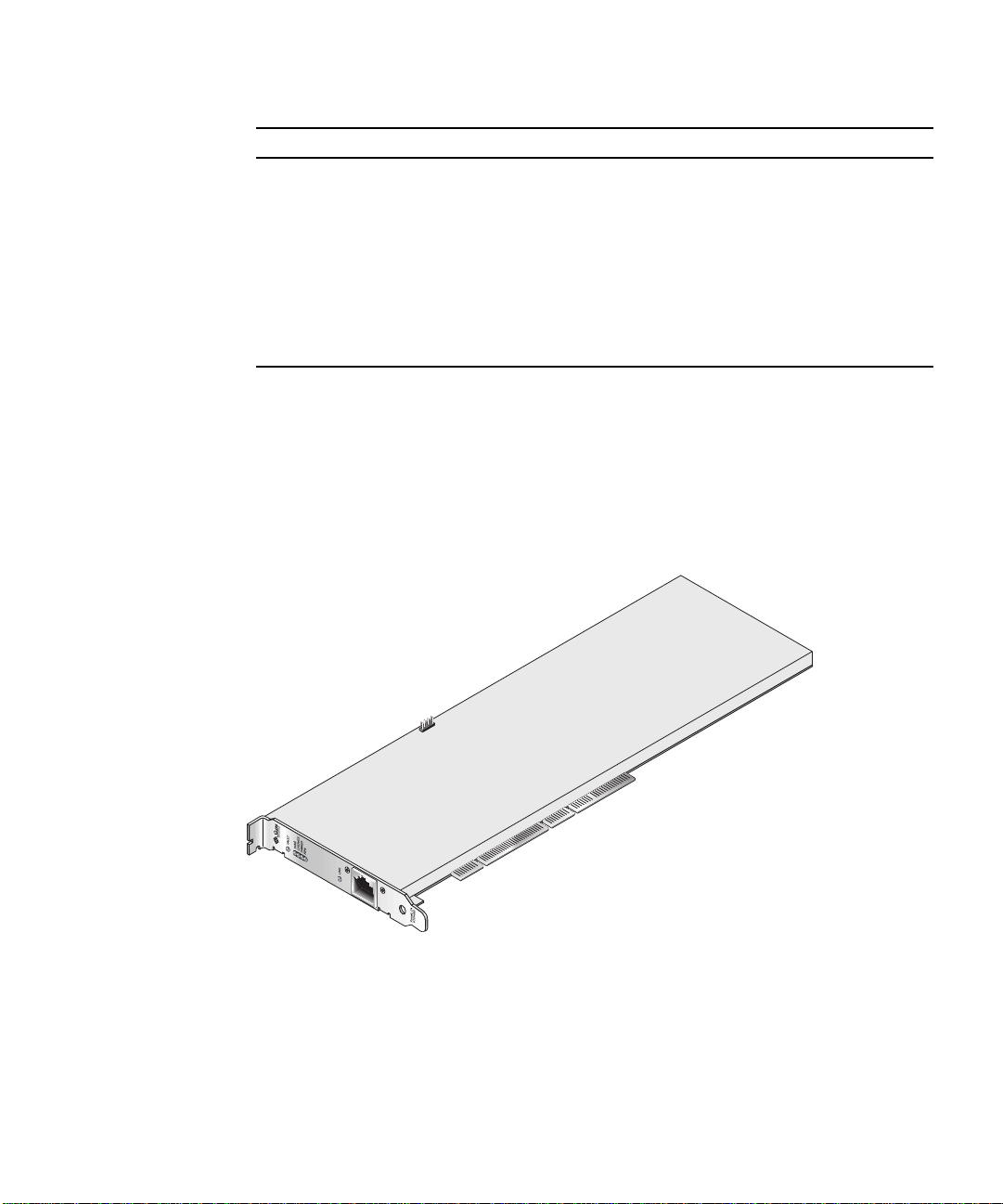
TABLE1-4 Front Panel Display LEDs for the MMF Adapter (Continued)
Label Meaning if Lit Color
Init On if the security officer has initialized the
board with vcaadm. See “Initializing the
Sun Crypto Accelerator 4000 Board With
vcaadm” on page 65.
Flashing if the ZEROIZE jumper is present.
FIPS Mode On when operating in FIPS 140-2 level 3
certified mode. Off when in non-FIPS
mode.
Link Link up. Green
Green
Green
Sun Crypto Accelerator 4000 UTP Adapter
The Sun Crypto Accelerator 4000 UTP adapter is a single-port Gigabit Ethernet
copper-based PCI bus card. It can be configured to operate in 10, 100, or 1000 Mbps
Ethernet networks.
FIGURE 1-2 Sun Crypto Accelerator 4000 UTP Adapter
Chapter 1 Product Overview 7
Page 34

LED Displays
See TABLE 1-5.
TABLE1-5 Front Panel Display LEDs for the UTP Adapter
Label Meaning if Lit Color
Fault On when the board is HALTED (fatal error)
state or low level hardware initialization
failed.
Flashing if an error occurred during the
boot process.
Diag On in POST, DIAGNOSTICS, and
FAILSAFE (firmware not upgraded) state.
Flashing when running DIAGNOSTICS.
Operate On in POST, DIAGNOSTICS, and
DISABLED (driver not attached) state.
Flashing in IDLE, OPERATIONAL, and
FAILSAFE states.
Init On if the security officer has initialized the
board with vcaadm. See “Initializing the
Sun Crypto Accelerator 4000 Board With
vcaadm” on page 65.
Flashing if the ZEROIZE jumper is present.
FIPS Mode On when operating in FIPS 140-2 level 3
certified mode. Off when in non-FIPS
mode.
1000 Indicates Gigabit Ethernet. Green
Activity (no label) Link is transmitting or receiving. Amber
Link (no label) Link up. Green
Red
Green
Green
Green
Green
Note – The service pack numbers (SP9 or SP1) are implied whenever Sun ONE Web
Server 4.1 or 6.0 is mentioned.
8 Sun Crypto Accelerator 4000 Board Installation and User’s Guide • May 2003
Page 35

Dynamic Reconfiguration and High Availability
The Sun Crypto Accelerator 4000 hardware and associated software provides the
capability to work effectively on Sun platforms supporting Dynamic Reconfiguration
(DR) and hot-plugging. During a DR or hot-plug operation, the Sun Crypto
Accelerator 4000 software layer automatically detects the addition or removal of a
board and adjusts the scheduling algorithms to accommodate the change in
hardware resources.
For High Availability (HA) configurations, multiple Sun Crypto Accelerator 4000
boards can be installed within a system or domain to insure that hardware
acceleration is continuously available. In the unlikely event of a Sun Crypto
Accelerator 4000 hardware failure, the software layer detects the failure and removes
the failed board from the list of available hardware cryptographic accelerators. Sun
Crypto Accelerator 4000 adjusts the scheduling algorithms to accommodate the
reduction in hardware resources. Subsequent cryptographic requests are scheduled
to the remaining boards.
Note that the Sun Crypto Accelerator 4000 hardware provides a source for highquality entropy for the generation of long-term keys. If all the Sun Crypto
Accelerator 4000 boards within a domain or system are removed, long-term keys are
generated with lower-quality entropy.
Load Sharing
The Sun Crypto Accelerator 4000 software distributes load across as many boards as
are installed within the Solaris domain or system. Incoming cryptographic requests
are distributed across the boards based on fixed-length work queues. Cryptographic
requests are directed to the first board, and subsequent requests stay directed to the
first board until it is running at full capacity. Once the first board is running at full
capacity, further requests are queued to the first board available that can accept the
request of this type. The queueing mechanism is designed to optimize throughput
by facilitating request coalescing at the board.
Chapter 1 Product Overview 9
Page 36

Hardware and Software Requirements
TABLE 1-6 provides a summary of the hardware and software requirements for the
Sun Crypto Accelerator 4000 adapter.
TABLE1-6 Hardware and Software Requirements
Hardware and Software Requirements
Hardware Sun Fire™ V120, V210, V240, 280R, V480, V880, 4800, 4810, 6800,
12K, 15K; Netra™ 20 (lw4); Sun Blade™ 100, 150, 1000, 2000
Operating
Environment
Required Patches
Refer to the Sun Crypto Accelerator 4000 Board Release Notes for additional required
patch information.
The following patches may be required to run the Sun Crypto Accelerator 4000
board on your system. Solaris updates contain patches to previous releases. Use the
showrev -p command to determine whether the listed patches have already been
installed.
Solaris 8 2/02 and future compatible releases (Solaris 9 is required
for IPsec acceleration.)
You can download the patches from the following web site:
http://sunsolve.sun.com.
Install the latest version of the patches. The dash number (-01, for example) becomes
higher with each new revision of the patch. If the version on the web site is higher
than that shown in the following tables, it is simply a later version.
If the patch you need is not available on SunSolve
service representative.
Apache Web Server Patch
If you plan to use the Apache Web Server, you must also install Patch 109234-09.
Once the SUNWkcl2a package is added, the system will be configured with Apache
Web Server mod_ssl 1.3.26.
10 Sun Crypto Accelerator 4000 Board Installation and User’s Guide • May 2003
SM
, contact your local sales or
Page 37

Solaris 8 Patches
The following tables list required and recommended Solaris 8 patches to use with
this product.
TABLE1-7 Required Solaris 8 Patches for Sun Crypto Accelerator 4000 Software
Patch-ID Description
110383-01 libnvpair
108528-05 KU-05 (nvpair support)
112438-01 /dev/random
TABLE 1-7 lists and describes required patches.
Solaris 9 Patches
There are currently no required Solaris 9 patches.
Chapter 1 Product Overview 11
Page 38

12 Sun Crypto Accelerator 4000 Board Installation and User’s Guide • May 2003
Page 39

CHAPTER
2
Installing the Sun Crypto Accelerator 4000 Board
This chapter describes how to install the Sun Crypto Accelerator 4000 hardware and
software. This chapter includes the following sections:
■ “Handling the Board” on page 13
■ “Installing the Board” on page 14
■ “Installing the Sun Crypto Accelerator 4000 Software” on page 16
■ “Directories and Files” on page 19
■ “Removing the Software” on page 21
Handling the Board
Each board is packed in a special antistatic bag to protect it during shipping and
storage. To avoid damaging the static-sensitive components on the board, reduce
any static electricity on your body before touching the board by using one of the
following methods:
■ Touch the metal frame of the computer.
■ Attach an antistatic wrist strap to your wrist and to a grounded metal surface.
Caution – To avoid damaging the sensitive components on the board, wear an
antistatic wrist strap when handling the board, hold the board by its edges only, and
always place the board on an antistatic surface (such as the plastic bag it came in).
13
Page 40

Installing the Board
Installing the Sun Crypto Accelerator 4000 board involves inserting the board into
the system and loading the software tools. The hardware installation instructions
include only general steps for installing the board. Refer to the documentation that
came with your system for specific installation instructions.
▼ To Install the Hardware
1. As superuser, follow the instructions that came with your system to shut down
and power off the computer, disconnect the power cord, and remove the computer
cover.
2. Locate an unused PCI slot (preferably a 64 bit, 66 MHz slot).
3. Attach an antistatic wrist strap to your wrist, and attach the other end to a
grounded metal surface.
4. Using a Phillips-head screwdriver, remove the screw from the PCI slot cover.
Save the screw to hold the bracket in Step 5.
5. Holding the Sun Crypto Accelerator 4000 board by its edges only, take it out of the
plastic bag and insert it into the PCI slot, and then secure the screw on the rear
bracket.
6. Replace the computer cover, reconnect the power cord, and power on the system.
7. Verify that the board is properly installed by issuing the show-devs command at
the OpenBoot™ PROM (OBP) ok prompt:
ok show-devs
.
/chosen
/packages
/upa@8,480000/SUNW,ffb@0,0
/pci@8,600000/network@1
/pci@8,600000/SUNW,qlc@4
/pci@8,600000/SUNW,qlc@4/fp@0,0
.
In the preceding example, the /pci@8,600000/network@1 identifies the device
path to the Sun Crypto Accelerator 4000 board. There will be one such line for each
board in the system.
14 Sun Crypto Accelerator 4000 Board Installation and User’s Guide • May 2003
Page 41

To determine whether the Sun Crypto Accelerator 4000 device properties are listed
correctly: from the ok prompt, navigate to the device path and type .properties
to display the list of properties.
ok cd /pci@8,600000/network@1
ok .properties
assigned-addresses 82000810 00000000 00102000 00000000 00002000
81000814 00000000 00000400 00000000 00000100
82000818 00000000 00200000 00000000 00200000
82000830 00000000 00400000 00000000 00100000
d-fru-len 00 00 00 00
d-fru-off 00 00 e8 00
d-fru-dev eeprom
s-fru-len 00 00 08 00
s-fru-off 00 00 e0 00
s-fru-dev eeprom
compatible 70 63 69 38 30 38 36 2c 62 35 35 35 2e 31 30 38
reg 00000800 00000000 00000000 00000000 00000000
02000810 00000000 00000000 00000000 00002000
02000814 00000000 00000000 00000000 00000100
02000818 00000000 00000000 00000000 00200000
02000830 00000000 00000000 00000000 00100000
address-bits 00 00 00 30
max-frame-size 00 00 40 00
network-interface-type ethernet
device_type network
name network
local-mac-address 08 00 20 aa bb cc
version Sun PCI Crypto Accelerator 4000 1000Base-T FCode
2.11.12 02/10/31
phy-type mif
board-model 501-6039
model SUNW,pci-vca
fcode-rom-offset 00000000
66mhz-capable
fast-back-to-back
devsel-speed 00000001
class-code 00100000
interrupts 00000001
latency-timer 00000040
cache-line-size 00000010
max-latency 00000040
min-grant 00000040
subsystem-id 00003de8
subsystem-vendor-id 0000108e
revision-id 00000002
device-id 0000b555
vendor-id 00008086
Chapter 2 Installing the Sun Crypto Accelerator 4000 Board 15
Page 42
Installing the Sun Crypto Accelerator 4000 Software
The Sun Crypto Accelerator 4000 software is included on the Sun Crypto Accelerator
4000 CD. You may need to download patches from the SunSolve web site. See
“Required Patches” on page 10 for more information.
▼ To Install the Software
1. Insert the Sun Crypto Accelerator 4000 CD into a CD-ROM drive that is connected
to your system.
■ If your system is running Sun Enterprise Volume Manager™, it should
automatically mount the CD-ROM to the /cdrom/cdrom0 directory.
■ If your system is not running Sun Enterprise Volume Manager, mount the CD-
ROM as follows:
# mount -F hsfs -o ro /dev/dsk/c0t6d0s2 /cdrom
16 Sun Crypto Accelerator 4000 Board Installation and User’s Guide • May 2003
Page 43

You see the following files and directories in the /cdrom/cdrom0 directory.
TABLE2-1 Files in the /cdrom/cdrom0 Directory
File or Directory Contents
Copyright U.S. copyright file
FR_Copyright French copyright file
Docs Sun Crypto Accelerator 4000 Board Installation and User’s Guide
Sun Crypto Accelerator 4000 Board Release Notes
Packages Contains the Sun Crypto Accelerator 4000 software packages:
SUNWkcl2r Cryptography Kernel Components
SUNWkcl2u Cryptographic Administration Utility and Libraries
SUNWkcl2a SSL Support for Apache (optional)
SUNWkcl2m Cryptographic Administration Manual Pages (optional)
SUNWvcar VCA Crypto Accelerator (Root)
SUNWvcau VCA Crypto Accelerator (Usr)
SUNWvcaa VCA Administration
SUNWvcafw VCA Firmware
SUNWvcamn VCA Crypto Accelerator Manual Page (optional)
SUNWvcav SunVTS Test of VCA Crypto Accelerator (optional)
SUNWkcl2o SSL Development Tools and Libraries (optional)
SUNWkcl2i.u IPSec Acceleration with KCLv2 Crypto (optional)
The required packages must be installed in a specific order and must be installed
before installing any optional packages. Once the required packages are installed,
you can install and remove the optional packages in any order.
Install the optional SUNWkcl2a package only if you plan to use Apache as your web
server.
Install the optional SUNWkcl2o package only if you plan to relink to another
(unsupported) version of Apache Web Server.
Install the optional SUNWvcav package only if you plan to perform the SunVTS tests.
You must have SunVTS 4.4 or later up to 5.x installed to install the SUNWvcav
package.
Note – The optional SUNWkcl2i.u package has the .u extension only on the Sun
Crypto Accelerator 4000 CD. Once this package is installed, the name is changed to
SUNWkcl2i. The .u extension of this package on the CD, defines the package as
sun4u architecture-specific.
Chapter 2 Installing the Sun Crypto Accelerator 4000 Board 17
Page 44

2. Install the required software packages by typing:
# cd /cdrom/cdrom0/Packages
# pkgadd -d . SUNWkcl2r SUNWkcl2u SUNWvcar SUNWvcau SUNWvcaa SUNWvcafw
3. (Optional) To verify that the software is installed properly, run the pkginfo
command.
# pkginfo SUNWkcl2r SUNWkcl2u SUNWvcar SUNWvcau SUNWvcaa SUNWvcafw
system SUNWkcl2r Cryptography Kernel Components
system SUNWkcl2u Cryptographic Administration Utility and Libraries
system SUNWvcar VCA
system SUNWvcau Crypto Accelerator/Gigabit Ethernet (Usr)
system SUNWvcaa VCA Administration
system SUNWvcafw VCA Firmware
Crypto Accelerator (Root)
4. (Optional) To ensure that the driver is attached, you can run the prtdiag
command. Refer to the prtdiag(1m) online manual pages.
# prtdiag -v
5. (Optional) Run the modinfo command to see that modules are loaded.
# modinfo | grep Crypto
62 1317f62 20b1f 198 1 vca (VCA Crypto/Ethernet v1.102)
63 13360e9 12510 200 1 kcl2 (Kernel Crypto Library v1.148)
197 136d5d6 19b0 199 1 vcactl (VCA Crypto Control v1.19)
Installing the Optional Packages
To install only the optional packages that provide the SSL support for Apache Web
Server and the cryptographic administration utility and libraries, type the following:
# cd /cdrom/cdrom0/Packages
# pkgadd -d . SUNWkcl2a SUNWkcl2m
18 Sun Crypto Accelerator 4000 Board Installation and User’s Guide • May 2003
Page 45

To install all of the optional software packages, type the following:
# cd /cdrom/cdrom0/Packages
# pkgadd -d . SUNWkcl2a SUNWkcl2m SUNWvcamn SUNWvcav SUNWkcl2o SUNWkcl2i.u
Refer to
TABLE 2-1 for a description of the package contents of the optional packages
in the previous examples.
Directories and Files
TABLE 2-2 shows the directories created by the default installation of the Sun Crypto
Accelerator 4000 software.
TABLE2-2 Sun Crypto Accelerator 4000 Directories
Directory Contents
/etc/opt/SUNWconn/vca/keydata
/opt/SUNWconn/cryptov2/bin
/opt/SUNWconn/cryptov2/lib
/opt/SUNWconn/cryptov2/sbin
FIGURE 2-1 shows the hierarchy of these directories and files.
Keystore data (encrypted)
Utilities
Support libraries
Administrative commands
Chapter 2 Installing the Sun Crypto Accelerator 4000 Board 19
Page 46
/
/bin
Application
executables
/etc
/opt
/SUNWconn
/vca
/keydata
Encrypted
keys
/include
Development
support
FIGURE 2-1 Sun Crypto Accelerator 4000 Directories and Files
/lib
Application
libraries
/man
Manual
pages
/opt
/SUNWconn
/cryptov2
/sbin
Daemon
executables
/ssl
Apache
configuration
support
Note – Once you have installed the hardware and software of the board, you need
to initialize the board with configuration and keystore information. Refer to
“Initializing the Sun Crypto Accelerator 4000 Board With vcaadm” on page 65 for
information on how to initialize the board.
20 Sun Crypto Accelerator 4000 Board Installation and User’s Guide • May 2003
Page 47
Removing the Software
If you have created keystores (refer to “Managing Keystores With vcaadm” on
page 69), you must delete the keystore information that the Sun Crypto Accelerator
4000 board is configured with before removing the software. The zeroize
command removes all key material, but does not delete the keystore files which are
stored in the filesystem of the physical host in which the Sun Crypto Accelerator
4000 board is installed. Refer to the “Zeroizing a Sun Crypto Accelerator 4000
Board” on page 80 for details on the zeroize command. To delete the keystore files
stored in the system, become superuser and remove the keystore files. If you have
not yet created any keystores, you can skip this procedure.
Caution – You must not delete a keystore that is currently in use or that is shared
by other users and keystores. To free references to keystores, you might have to shut
down the web server and/or administration server.
Caution – Before removing the Sun Crypto Accelerator 4000 software you must
disable any web servers you have enabled for use with the Sun Crypto Accelerator
4000 board. Failure to do so will leave those web servers nonfunctional.
▼ To Remove the Software
● As superuser, use the pkgrm command to remove only the software packages you
installed.
Caution – Installed packages must be removed in the order shown. Failure to
remove them in this order could result in dependency warnings and leave kernel
modules loaded.
If you installed all the packages, you would remove them as follows:
# pkgrm SUNWkcl2o SUNWvcav SUNWvcar SUNWkcl2a SUNWkcl2u SUNWkcl2r
SUNWvcamn SUNWkcl2m SUNWkcl2i SUNWvcaa SUNWvcafw SUNWvcau
Chapter 2 Installing the Sun Crypto Accelerator 4000 Board 21
Page 48

Note – After installing or removing the SunVTS test (SUNWvcav) for the Sun Crypto
Accelerator 4000 board, if SunVTS is already running it might be necessary to
reprobe the system to update the available tests. See your SunVTS documentation
for more information.
22 Sun Crypto Accelerator 4000 Board Installation and User’s Guide • May 2003
Page 49

CHAPTER
3
Configuring Driver Parameters
This chapter describes how to configure the vca device driver parameters used by
both the Sun Crypto Accelerator 4000 UTP and MMF Ethernet adapters. This chapter
contains the following sections:
■ “Sun Crypto Accelerator 4000 Ethernet Device Driver (vca) Parameters” on
page 23
■ “Setting vca Driver Parameters” on page 33
■ “Enabling Autonegotiation or Forced Mode for Link Parameters With the
OpenBoot PROM” on page 41
■ “Sun Crypto Accelerator 4000 Cryptographic and Ethernet Driver Operating
Statistics” on page 43
■ “Network Configuration” on page 52
Sun Crypto Accelerator 4000 Ethernet Device Driver (vca) Parameters
The vca device driver controls the Sun Crypto Accelerator 4000 UTP and MMF
Ethernet devices. The vca driver is attached to the UNIX pci name property
pci108e,3de8 for the Sun Crypto Accelerator 4000 (108e is the vendor ID and
3de8 is the PCI device ID).
You can manually configure the vca device driver parameters to customize each Sun
Crypto Accelerator 4000 device in your system. This section provides an overview of
the capabilities of the Sun Crypto Accelerator 4000 Ethernet device used in the
board, lists the available vca device driver parameters, and describes how to
configure these parameters.
The Sun Crypto Accelerator 4000 Ethernet UTP and MMF PCI adapters are capable
of the operating speeds and modes listed in “Setting Autonegotiation or Forced
Mode” on page 36. By default, the vca device operates in autonegotiation mode
23
Page 50

with the remote end of the link (link partner) to select a common mode of operation
for the speed, duplex, and link-clock parameters. The link-clock parameter
is applicable only if the board is operating at a 1000 Mbps. The vca device can also
be configured to operate in forced mode for each of these parameters.
Caution – To establish a proper link, both link partners must operate in either
autonegotiation or forced mode for each of the speed, duplex, and link-clock
(1000 Mbps only) parameters. If both link partners are not operating in the same
mode for each of these parameters, network errors will occur. See “Enabling
Autonegotiation or Forced Mode for Link Parameters With the OpenBoot PROM” on
page 41.
Driver Parameter Values and Definitions
TABLE 3-1 describes the parameters and settings for the vca device driver.
TABLE3-1 vca Driver Parameter, Status, and Descriptions
Parameter Status Description
instance Read and write Device instance
adv-autoneg-cap Read and write Operational mode parameter
adv-1000fdx-cap Read and write Operational mode parameter (MMF adapter only)
adv-1000hdx-cap Read and write Operational mode parameter
adv-100fdx-cap Read and write Operational mode parameter (UTP adapter only)
adv-100hdx-cap Read and write Operational mode parameter (UTP adapter only)
adv-10fdx-cap Read and write Operational mode parameter (UTP adapter only)
adv-10hdx-cap Read and write Operational mode parameter (UTP adapter only)
adv-asmpause-cap Read and write Flow control parameter
adv-pause-cap Read and write Flow control parameter
pause-on-threshold Read and write Flow control parameter
pause-off-threshold Read and write Flow control parameter
link-master Read and write 1 Gbps speed forced mode parameter
enable-ipg0 Read and write Enable additional delay before transmitting a packet
ipg0 Read and write Additional delay before transmitting a packet
ipg1 Read and write Interpacket Gap parameter
24 Sun Crypto Accelerator 4000 Board Installation and User’s Guide • May 2003
Page 51

TABLE3-1 vca Driver Parameter, Status, and Descriptions (Continued)
Parameter Status Description
ipg2 Read and write Interpacket Gap parameter
rx-intr-pkts Read and write Receive interrupt blanking values
rx-intr-time Read and write Receive interrupt blanking values
red-dv4to6k Read and write Random early detection and packet drop vectors
red-dv6to8k Read and write Random early detection and packet drop vectors
red-dv8to10k Read and write Random early detection and packet drop vectors
red-dv10to12k Read and write Random early detection and packet drop vectors
tx-dma-weight Read and write PCI Interface parameter
rx-dma-weight Read and write PCI Interface parameter
infinit-burst Read and write PCI Interface parameter
disable-64bit Read and write PCI Interface parameter
Advertised Link Parameters
The following parameters determine the transmit and receive speed and duplex
link parameters to be advertised by the vca driver to its link partner.
describes the operational mode parameters and their default values.
TABLE 3-2
Note – If a parameter’s initial setting is 0, it cannot be changed. If you try to change
an initial setting of 0, it will revert back to 0. By default, these parameters are set to
the capabilities of the vca device.
Chapter 3 Configuring Driver Parameters 25
Page 52

The Sun Crypto Accelerator 4000 UTP adapter advertised link parameters are
different from those of the Sun Crypto Accelerator 4000 MMF adapter as shown in
TABLE 3-2.
TABLE3-2 Operational Mode Parameters
Parameter Description
The following parameter is for both the Sun Crypto Accelerator 4000 UTP and MMF adapters.
adv-autoneg-cap Local interface capability advertised by the hardware
0 = Forced mode
1 = Autonegotiation (default)
The following parameter is for the Sun Crypto Accelerator 4000 MMF adapter only.
adv-1000fdx-cap Local interface capability advertised by the hardware
0 = Not 1000 Mbps full-duplex capable
1 = 1000 Mbps full-duplex capable (default)
The following parameter is for both the Sun Crypto Accelerator 4000 UTP and MMF adapters.
adv-1000hdx-cap Local interface capability advertised by the hardware
0 = Not 1000 Mbps half-duplex capable
1 = 1000 Mbps half-duplex capable (default)
The following parameters are for the Sun Crypto Accelerator 4000 UTP adapter only.
adv-100fdx-cap Local interface capability advertised by the hardware
0 = Not 100 Mbps full-duplex capable
1 = 100 Mbps full-duplex capable (default)
adv-100hdx-cap Local interface capability advertised by the hardware
0 = Not 100 Mbps half-duplex capable
1 = 100 Mbps half-duplex capable (default)
adv-10fdx-cap Local interface capability advertised by the hardware
0 = Not 10 Mbps full-duplex capable
1 = 10 Mbps full-duplex capable (default)
adv-10hdx-cap Local interface capability advertised by the hardware
0 = Not 10 Mbps half-duplex capable
1 = 10 Mbps half-duplex capable (default)
26 Sun Crypto Accelerator 4000 Board Installation and User’s Guide • May 2003
Page 53

If all of the previous parameters are set to 1, autonegotiation will use the highest
speed possible. If all of the previous parameters are set to 0, you will receive the
following error message:
NOTICE: Last setting will leave vca0 with no link capabilities.
WARNING: vca0: Restoring previous setting.
Note – In the previous example, vca0 is the Sun Crypto Accelerator 4000 board
device name where the string, vca, is used for every Sun Crypto Accelerator 4000
board. This string is always immediately followed by the device instance number of
the board. Hence, the device instance number of the vca0 board is 0.
Flow Control Parameters
The vca device is capable of sourcing (transmitting) and terminating (receiving)
pause frames conforming to the IEEE 802.3x Frame Based Link Level Flow Control
Protocol. In response to received flow control frames, the vca device is capable of
reducing its transmit rate. Alternately, the vca device is capable of sourcing flow
control frames, requesting the link partner to reduce its transmit rate if the link
partner supports this feature. By default, the driver advertises both transmit and
receive pause capability during autonegotiation.
TABLE 3-3 provides flow control keywords and describes their function.
TABLE3-3 Read-Write Flow Control Keyword Descriptions
Keyword Description
adv-asmpause-cap Both the MMF and UTP adapters support asymmetric pause; hence, the vca
device can pause only in one direction.
0=Off (default)
1=On
adv-pause-cap This parameter has two meanings depending on the value of
adv-asmpause-cap. (Default=0)
Parameter Value + Parameter Value =
adv-asmpause-cap= adv-pause-cap=
11or0adv-pause-cap determines which
1 1 Pauses are received but are not
Description
direction pauses operate on.
transmitted.
Chapter 3 Configuring Driver Parameters 27
Page 54

TABLE3-3 Read-Write Flow Control Keyword Descriptions
Keyword Description
1 0 Pauses are transmitted but are not
received.
0 1 Pauses are sent and received.
01or0adv-pause-cap determines
whether the pause capability is on
or off.
pause-on-threshold Defines the number of 64 byte blocks in the receive (RX) FIFO which causes the
board to generate an XON-PAUSE frame.
pause-off-threshold Defines the number of 64 byte blocks in the RX FIFO which causes the board to
generate an XOFF-PAUSE frame.
Gigabit Forced Mode Parameter
For Gigabit links, this parameter determines the link-master. Generally, switches
are enabled as a link master; in which case, this parameter can remain unchanged. If
this is not the case, then the link-master parameter can be used to enable the vca
device as a link master.
TABLE3-4 Gigabit Forced Mode Parameter
Parameter Description
link-master When set to 1 this parameter enables master operation, assuming
the link partner is a slave.
When set to 0 this parameter enables slave operation, assuming the
link partner is a master. (default)
Interpacket Gap Parameters
The vca device supports a programmable mode called enable-ipg0.
Before transmitting a packet with enable-ipg0 enabled (default), the vca device
adds an additional time delay. This delay, set by the ipg0 parameter, is in addition
to the delay set by the ipg1 and ipg2 parameters. The additional ipg0 delay
reduces collisions.
If enable-ipg0 is disabled, the value of ipg0 is ignored and no additional delay is
set. Only the delays set by ipg1 and ipg2 will be used. Disable enable-ipg0 if
other systems keep sending a large number of continuous packets. Systems that
28 Sun Crypto Accelerator 4000 Board Installation and User’s Guide • May 2003
Page 55

have enable-ipg0 enabled might not have enough time on the network. You can
add the additional delay by setting the ipg0 parameter from 0 to 255, which is the
media byte time delay.
TABLE3-5 Parameters Defining enable-ipg0 and ipg0
Parameter Values Description
enable-ipg0 0
ipg0 0 to 255 The additional time delay (or gap) before
TABLE 3-5 defines the enable-ipg0 and ipg0 parameters.
enable-ipg0 enable
1
enable-ipg0 disable (Default=1)
transmitting a packet (after receiving the
packet) (Default=8)
The vca device supports the programmable interpacket gap parameters (IPG) ipg1
and ipg2. The total IPG is the sum of ipg1 and ipg2. The total IPG is 0.096
microseconds for the link speed of 1000 Mbps.
TABLE 3-6 lists the default values and allowable values for the IPG parameters.
TABLE3-6 Read-Write Interpacket Gap Parameter Values and Descriptions
Parameter Values
(Byte-time)
ipg1 0 to 255 Interpacket gap 1 (Default=8)
ipg2 0 to 255 Interpacket gap 2 (Default=4)
Description
By default, the driver sets ipg1 to 8-byte time and ipg2 to 4-byte time, which are
the standard values. (Byte time is the time it takes to transmit one byte on the link,
with a link speed of 1000 Mbps.)
If your network has systems that use longer IPG (the sum of ipg1 and ipg2), and if
those machines seem to be slow in accessing the network, increase the values of
ipg1 and ipg2 to match the longer IPGs of other machines.
Chapter 3 Configuring Driver Parameters 29
Page 56

Interrupt Parameters
TABLE 3-7 describes the receive interrupt blanking values.
TABLE3-7 RX Blanking Register for Alias Read
Field Name Values Description
rx-intr-pkts 0 to 511 Interrupts after this number of packets have arrived
since the last packet was serviced. A value of zero
indicates no packet blanking. (Default=3)
rx-intr-time 0 to 524287 Interrupts after 4.5 microseconds (usecs) have elapsed
since the last packet was serviced. A value of zero
indicates no time blanking. (Default=3)
Random Early Drop Parameters
These parameters provide the ability to drop packets based on the fullness of the
receive FIFO. By default, this feature is disabled. When FIFO occupancy reaches a
specific range, packets are dropped according to the preset probability. The
probability should increase when the FIFO level increases. Control packets are never
dropped and are not counted in the statistics.
TABLE3-8 RX Random Early Detecting 8-Bit Vectors
Field Name Values Description
red-dv4to6k 0 to 255 Random early detection and packet drop vectors for
when FIFO threshold is greater than 4096 bytes and less
than 6,144 bytes. Probability of drop can be
programmed on a 12.5 percent granularity. For
example, if bit 0 is set, the first packet out of every
eight will be dropped in this region. (Default=0)
30 Sun Crypto Accelerator 4000 Board Installation and User’s Guide • May 2003
Page 57

TABLE3-8 RX Random Early Detecting 8-Bit Vectors (Continued)
Field Name Values Description
red-dv6to8k 0 to 255 Random early detection and packet drop vectors for
when FIFO threshold is greater than 6,144 bytes and
less than 8,192 bytes. Probability of drop can be
programmed on a 12.5 percent granularity. For
example, if bit 8 is set, the first packet out of every
eight will be dropped in this region. (Default=0)
red-dv8to10k 0 to 255 Random early detection and packet drop vectors for
when FIFO threshold is greater than 8,192 bytes and
less than 10,240 bytes. Probability of drop can be
programmed on a 12.5 percent granularity. For
example, if bit 16 is set, the first packet out of every
eight will be dropped in this region. (Default=0)
red-dv10to12k 0 to 255 Random early detection and packet drop vectors for
when FIFO threshold is greater than 10,240 bytes and
less than 12,288 bytes. Probability of drop can be
programmed on a 12.5 percent granularity. For
example, if bit 24 is set, the first packet out of every
eight will be dropped in this region. (Default=0)
Chapter 3 Configuring Driver Parameters 31
Page 58

PCI Bus Interface Parameters
These parameters allow you to modify PCI interface features to gain better PCI
interperformance for a given application.
TABLE3-9 PCI Bus Interface Parameters
Parameter Description
tx-dma-weight Determines the multiplication factor for granting credit to the
transmit (TX) side during a weighted round robin arbitration; the
values are 0 to 3 (Default=0). Zero means no extra weighting. The
other values are power of 2 extra weighting on that traffic. For
example, if tx-dma-weight = 0 and rx-dma-weight = 3, then as
long as RX traffic is continuously arriving, the priority of RX traffic
will be 8 times greater than the priority of TX traffic to access the
PCI.
rx-dma-weight Determines the multiplication factor for granting credit to the RX
side during a weighted round robin arbitration. The values are 0 to
3 (Default=0).
infinite-burst Allows the infinite burst capability to be used when this parameter
is enabled and the system supports infinite burst. The adapter will
not free the bus until complete packets are transferred across the
bus. The values are 0 or 1 (Default=0).
disable-64bit Switches off 64-bit capability of the adapter.
®
Note: for UltraSPARC
set to 1 by default. For UltraSPARC II based platforms, the default is
0. The values are 0 or 1 (Default=0, which enables 64-bit capability).
32 Sun Crypto Accelerator 4000 Board Installation and User’s Guide • May 2003
III based platforms, this parameter may be
Page 59

Setting vca Driver Parameters
You can set the vca device driver parameters in two ways:
■ Using the ndd utility
■ Using the vca.conf file
If you use the ndd utility, the parameters are valid only until you reboot the system.
This method is good for testing parameter settings.
To set parameters so they remain in effect after you reboot the system, create a
/kernel/drv/vca.conf file and add parameter values to this file when you need
to set a particular parameter for a device in the system. See “To Set Driver
Parameters Using a vca.conf File” on page 38 for details.
Setting Parameters Using the ndd Utility
Use the ndd utility to configure parameters that are valid until you reboot the
system.
The following sections describe how you can use the vca driver and the ndd utility
to modify (with the -set option) or display (without the -set option) the
parameters for each vca device.
▼ To Specify Device Instances for the ndd Utility
Before you use the ndd utility to get or set a parameter for a vca device, you must
specify the device instance for the utility.
1. Check the /etc/path_to_inst file to identify the instance number associated
with a particular device. Refer to the online manual pages for path_to_inst(4).
# grep vca /etc/path_to_inst
"/pci@8,600000/network@1" 0 "vca"
"/pci@8,700000/network@1" 1 "vca"
In the previous example, the three Sun Crypto Accelerator 4000 Ethernet instances
are from the installed adapters. The instance numbers are 0 and 1.
2. Use the instance number to select the device.
# ndd -set /dev/vcaN
Chapter 3 Configuring Driver Parameters 33
Page 60

Note – In the examples in this user’s guide, N represents the instance number of the
device.
The device remains selected until you change the selection.
Noninteractive and Interactive Modes
You can use the ndd utility in two modes:
■ Noninteractive
■ Interactive
In noninteractive mode, you invoke the utility to execute a specific command. Once
the command is executed, you exit the utility. In interactive mode, you can use the
utility to get or set more than one parameter value. Refer to the ndd(1M) online
manual page for more information.
Using the ndd Utility in Noninteractive Mode
This section describes how to modify and display parameter values.
● To modify a parameter value, use the -set option.
If you invoke the ndd utility with the -set option, the utility passes value, which
must be specified to the named /dev/vca driver instance, and assigns it to the
parameter:
# ndd -set /dev/vcaN parameter value
When you change any adv parameter, a message similar to the following appears:
- link up 1000 Mbps half duplex
● To display the value of a parameter, specify the parameter name and omit the
value.
When you omit the -set option, a query operation is assumed and the utility
queries the named driver instance, retrieves the value associated with the specified
parameter, and prints it:
# ndd /dev/vcaN parameter
34 Sun Crypto Accelerator 4000 Board Installation and User’s Guide • May 2003
Page 61

Using the ndd Utility in Interactive Mode
● To modify a parameter value in interactive mode, specify ndd /dev/vca,as
shown below.
The ndd utility then prompts you for the name of the parameter:
# ndd /dev/vcaN
name to get/set? (Enter the parameter name or ? to view all
parameters)
After typing the parameter name, the ndd utility prompts you for the parameter
value (see
TABLE 3-1 through TABLE 3-9).
Chapter 3 Configuring Driver Parameters 35
Page 62

● To list all the parameters supported by the vca driver, type ndd /dev/vca.
TABLE 3-1 through TABLE 3-9 for parameter descriptions.)
(See
# ndd /dev/vca
name to get/set ? ?
? (read only)
instance (read and write)
adv-autoneg-cap (read and write)
adv-1000fdx-cap (read and write)
adv-1000hdx-cap (read and write)
adv-100fdx-cap (read and write)
adv-100hdx-cap (read and write)
adv-10fdx-cap (read and write)
adv-10hdx-cap (read and write)
adv-asmpause-cap (read and write)
adv-pause-cap (read and write)
pause-on-threshold (read and write)
pause-off-threshold (read and write)
link-master (read and write)
enable-ipg0 (read and write)
ipg0 (read and write)
ipg1 (read and write)
ipg2 (read and write)
rx-intr-pkts (read and write)
rx-intr-time (read and write)
red-p4k-to-6k (read and write)
red-p6k-to-8k (read and write)
red-p8k-to-10k (read and write)
red-p10k-to-12k (read and write)
tx-dma-weight (read and write)
rx-dma-weight (read and write)
infinite-burst (read and write)
disable-64bit (read and write)
name to get/set ?
#
Setting Autonegotiation or Forced Mode
The following link parameters can be set to operate in either autonegotiation or
forced mode:
■ speed
■ duplex
■ link-clock
36 Sun Crypto Accelerator 4000 Board Installation and User’s Guide • May 2003
Page 63

By default, autonegotiation mode is enabled for these link parameters. When either
of these parameters are in autonegotiation mode, the vca device communicates with
the link partner to negotiate a compatible value and flow control capability. When a
value other than auto is set for either of these parameters, no negotiation occurs
and the link parameter is configured in forced mode. In forced mode, the value for
the speed parameter must match between link partners. See “Enabling
Autonegotiation or Forced Mode for Link Parameters With the OpenBoot PROM” on
page 41.
▼ To Disable Autonegotiation Mode
If your network equipment does not support autonegotiation, or if you want to force
your network speed, duplex,orlink-clock parameters, you can disable the
autonegotiation mode on the vca device.
1. Set the following driver parameters to the values that are described in the
documentation delivered with your link partner device (for example, a switch):
■ adv-1000fdx-cap
■ adv-1000hdx-cap
■ adv-100fdx-cap
■ adv-100hdx-cap
■ adv-10fdx-cap
■ adv-10hdx-cap
■ adv-asmpause-cap
■ adv-pause-cap
TABLE 3-2 for the descriptions and possible values of these parameters.
See
2. Set the adv-autoneg-cap parameter to 0.
# ndd -set /dev/vcaN adv-autoneg-cap 0
When you change any ndd link parameter, a message similar to the following
appears:
link up 1000 Mbps half duplex
Note – If you disable autonegotiation, you must enable the speed, duplex, and
link-clock (1000 Mbps only) parameters to operate in forced mode. For
instructions, see “Enabling Autonegotiation or Forced Mode for Link Parameters
With the OpenBoot PROM” on page 41.
Chapter 3 Configuring Driver Parameters 37
Page 64

Setting Parameters Using the vca.conf File
You can also specify the driver parameter properties by adding entries to the
vca.conf file in the /kernel/drv directory. The parameter names are the same
names listed in “Driver Parameter Values and Definitions” on page 24.
Caution – Do not remove any of the default entries in the
/kernel/drv/vca.conf file.
The online manual pages for prtconf(1) and driver.conf(4) include additional
details. The next procedure shows an example of setting parameters in a vca.conf
file.
Variables defined in the previous section apply to known devices in the system. To
set a variable for a Sun Crypto Accelerator 4000 board with the vca.conf file, you
must know the following three pieces of information for the device: device name,
device parent, and device unit address.
▼ To Set Driver Parameters Using a vca.conf File
1. Obtain the hardware path names for the vca devices in the device tree.
a. Check the /etc/driver_aliases file to identify the name associated with a
particular device.
# grep vca /etc/driver_aliases
vca "pci108e,3de8"
In the previous example, the device name associated with the Sun Crypto
Accelerator 4000 software driver ( vca)is”pci108e,3de8”.
b. Locate the device parent name and device unit address in the
/etc/path_to_inst file.
Refer to the online manual pages for path_to_inst(4).
# grep vca /etc/path_to_inst
"/pci@8,600000/network@1" 0 "vca"
"/pci@8,700000/network@1" 1 "vca"
In the previous example, there are three columns of output: device path name,
instance number, and software driver name.
38 Sun Crypto Accelerator 4000 Board Installation and User’s Guide • May 2003
Page 65

The device path name in the first line of the previous example is
”/pci@8,600000/network@1”. Device path names are made up of three parts:
device parent name, device node name, and device unit address. See
TABLE3-10 Device Path Name
Entire Device Path Name Parent Name Portion Node Name Portion Unit Address Portion
"/pci@8,600000/network@1" /pci@8,600000 network 1
"/pci@8,700000/network@1" /pci@8,700000 network 1
TABLE 3-10.
To identify a PCI device unambiguously in the vca.conf file, use the entire device
path name (parent name, node name, and the unit address) for the device. Refer to
the pci(4) online manual page for more information about the PCI device
specification.
2. Set the parameters for the above devices in the /kernel/drv/vca.conf file.
In the following entry, the adv-autoneg-cap parameter is disabled for a particular
Sun Crypto Accelerator 4000 Ethernet device.
name="pci108e,3de8" parent="/pci@8,700000" unit-address="1" adv-autoneg-cap=0;
3. Save the vca.conf file.
4. Save and close all files and programs, and exit the windowing system.
5. Shut down and reboot the system.
Setting Parameters for All Sun Crypto Accelerator 4000 vca Devices With the vca.conf File
If you omit the device path name (parent name, node name, and the unit address),
the variable is set for all instances of all Sun Crypto Accelerator 4000 Ethernet
devices.
Chapter 3 Configuring Driver Parameters 39
Page 66

▼ To Set Parameters for All Sun Crypto Accelerator 4000 vca
Devices With the vca.conf File
1. Add a line in the vca.conf file to change the value of a parameter for all
instances by entering parameter=value;.
The following example sets the adv-autoneg-cap parameter to 1 for all instances
of all Sun Crypto Accelerator 4000 Ethernet devices:
adv-autoneg-cap
=1;
Example vca.conf File
The following is an example vca.conf file:
#
# Copyright 2002 Sun Microsystems, Inc. All rights reserved.
# Use is subject to license terms.
#
#ident "@(#)vca.conf 1.2 02/06/26 SMI"
#
# Use the new Solaris 9 properties to ensure that the driver is attached
# on boot, to get us to register with KCL2. This also prevents us from
# being unloaded by the cleanup modunload -i 0.
#
ddi-forceattach=1 ddi-no-autodetach=1;
name="pci108e,3de8" parent="/pci@8,700000" unit-address="1" adv-autoneg-cap=0;
adv-autoneg-cap=1;
40 Sun Crypto Accelerator 4000 Board Installation and User’s Guide • May 2003
Page 67

Enabling Autonegotiation or Forced Mode for Link Parameters With the OpenBoot PROM
The following parameters can be configured to operate in autonegotiation or forced
mode at the OpenBoot PROM (OBP) interface:
TABLE3-11 Local Link Network Device Parameters
Parameter Description
speed This parameter can be set to auto, 1000, 100,or10; the syntax is as follows:
• speed=auto (default)
• speed=1000
• speed=100
• speed=10
duplex This parameter can be set to auto, full,orhalf; the syntax is as follows:
• duplex=auto (default)
• duplex=full
• duplex=half
link-clock This parameter is applicable only if the speed parameter is set to 1000 or if
you are using a 1000 Mbps MMF Sun Crypto Accelerator 4000 board. The
value for this parameter must correspond to the value on the link
partner—for example, if the local link has a value of master, the link partner
must have a value of slave. This parameter can be set to master, slave,or
auto; the syntax is as follows:
• link-clock=auto (default)
• link-clock=master
• link-clock=slave
To establish a proper link, the speed, duplex, and link-clock (1000 Mbps only)
parameters must be configured correctly between the local link and the link partner.
Both link partners must operate in either autonegotiation or forced mode for each of
the speed, duplex, and link-clock (1000 Mbps only) parameters. A value of
auto for any of these parameters configures the link to operate in autonegotiation
mode for that parameter. The absence of a parameter at the OBP prompt configures
that parameter to have a default value of auto. A value other than auto configures
the local link to operate in forced mode for that parameter.
Chapter 3 Configuring Driver Parameters 41
Page 68

When the local link is operating in autonegotiation mode for the speed and duplex
parameters at 100 Mbps and below and both full and half duplexes, then the link
partner uses either the 100 Mbps or 10 Mbps speeds with either duplex.
When the speed parameter is operating in forced mode, the value must match the
speed value of the link-partner. If the duplex parameter does not match between
the local link and the link partner, the link may come up; however, traffic collisions
will occur.
When the local link speed parameter is set to autonegotiation and the link partner
speed parameter is set to forced, the link may come up depending on whether the
speed value can be negotiated between the local link and the link partner. The
interface in autonegotiation mode will always try to establish a link (if there is a
speed match) at half duplex by default. Because one of the two interfaces is not in
autonegotiation mode, the interface in autonegotiation mode detects only the speed
parameter; the duplex parameter is not detected. This method is called paralleldetection.
Caution – The establishment of a link with a duplex conflict always leads to traffic
collisions.
For a local link parameter to operate in forced mode, the parameter must have a
value other than auto. For example, to establish a forced mode link at 100 Mbps
with half duplex, type the following at the OBP prompt:
ok boot net:speed=100,duplex=half
Note – In the examples in this section, net is an alias for the default, integrated
network interface device path. You can configure other network devices by
specifying a device path instead of using net.
To establish a forced mode link at 1000 Mbps with half duplex that is a clock master,
type the following command at the OBP prompt:
ok boot net:speed=1000,duplex=half,link-clock=master
Note – The link-clock parameter must have a value that corresponds to the
link-clock value of the link partner. For example, if the link-clock value on the
local link is set to master, the link-clock value on the link partner must be set to
slave.
42 Sun Crypto Accelerator 4000 Board Installation and User’s Guide • May 2003
Page 69

To establish a forced mode for a speed of 10 Mbps and an autonegotiation mode for
duplex, type the following at the OBP prompt:
ok boot net:speed=10,duplex=auto
You could also type the following at the OBP prompt to establish the same local link
parameters as the previous example:
ok boot net:speed=10
Refer to the IEEE 802.3 documentation for further details.
Sun Crypto Accelerator 4000 Cryptographic and Ethernet Driver Operating Statistics
This section describes the statistics presented by the kstat(1M) command.
Cryptographic Driver Statistics
TABLE 3-12 describes the cryptographic driver statistics.
TABLE3-12 Cryptographic Driver Statistics
Parameter Description Stable or Unstable
vs-mode The values are FIPS, standard,orunitialized.
FIPS indicates that the board is in FIPS mode.
standard indicates that the board is in not in
FIPS mode. unitialized indicates that the board
is not initialized.
vs-status The values are ready, faulted,orfailsafe.
ready indicates that the board is operating
normally. faulted indicates that the board not
operating. failsafe indicates failsafe mode
which is the original factory state of the board.
Chapter 3 Configuring Driver Parameters 43
Stable
Stable
Page 70

Ethernet Driver Statistics
TABLE 3-13 describes the Ethernet driver statistics.
TABLE3-13 Ethernet Driver Statistics
Parameter Description Stable or Unstable
ipackets Number of inbound packets. Stable
ipackets64 64-bit version of ipackets. Stable
ierrors Total packets received that could not be processed
because they contained errors (long).
opackets Total packets requested to be transmitted on the
interface.
opackets64 Total packets requested to be transmitted on the
interface (64-bit).
oerrors Total packets that were not successfully
transmitted because of errors (long).
rbytes Total bytes successfully received on the interface. Stable
rbytes64 Total bytes successfully received on the interface
(64-bit).
obytes Total bytes requested to be transmitted on the
interface.
obytes64 Total bytes requested to be transmitted on the
interface (64-bit).
multircv Multicast packets successfully received, including
group and functional addresses (long).
multixmt Multicast packets requested to be transmitted,
including group and functional addresses (long).
brdcstrcv Broadcast packets successfully received (long). Stable
brdcstxmt Broadcast packets requested to be transmitted
(long).
norcvbuf Times a valid incoming packet was known to have
been discarded because no buffer could be
allocated for receive (long).
noxmtbuf Packets discarded on output because transmit
buffer was busy, or no buffer could be allocated for
transmit (long).
Stable
Stable
Stable
Stable
Stable
Stable
Stable
Stable
Stable
Stable
Stable
Stable
44 Sun Crypto Accelerator 4000 Board Installation and User’s Guide • May 2003
Page 71

TABLE 3-14 describes the transmit and receive MAC counters.
TABLE3-14 TX and RX MAC Counters
Parameter Description Stable or Unstable
tx-collisions 16-bit loadable counter increments for
Stable
every frame transmission attempt that
resulted in a collision.
tx-first-collisions 16-bit loadable counter increments for
Unstable
every frame transmission that
experienced a collision on the first
attempt, but was successfully
transmitted on the second attempt.
tx-excessive-collisions 16-bit loadable counter increments for
Unstable
every frame transmission that has
exceeded the Attempts Limit.
tx-late-collisions 16-bit loadable counter increments for
Unstable
every frame transmission that has
experienced a collision. It indicates the
number of frames that the TxMAC has
dropped due to collisions that occurred
after it has transmitted at least the
Minimum Frame Size number of bytes.
Usually this is an indication that there
is at least one station on the network
that violates the maximum allowed
span of the network.
tx-defer-timer 16-bit loadable timer increments when
Unstable
the TxMAC is deferring to traffic on the
network while it is attempting to
transmit a frame. The time base for the
timer is the media byte clock divided by
256.
tx-peak-attempts 8-bit register indicates the highest
Unstable
number of consecutive collisions per
successfully transmitted frame, that
have occurred since this register was
last read. The maximum value that this
register can attain is 255. A maskable
interrupt is generated to the software if
the number of consecutive collisions
per successfully transmitted frame
exceeds 255. This register will be
automatically cleared at 0 after it is
read.
Chapter 3 Configuring Driver Parameters 45
Page 72

TABLE3-14 TX and RX MAC Counters (Continued)
Parameter Description Stable or Unstable
tx-underrun 16-bit loadable counter increments after
Unstable
a valid frame has been received from
the network.
rx-length-err 16-bit loadable counter increments after
Unstable
a frame, whose length is greater than
the value that was programmed in the
Maximum Frame Size Register, has
been received from the network.
rx-alignment-err 16-bit loadable counter increments
Unstable
when an alignment error is detected in
a receive frame. An alignment error is
reported when a receive frame fails the
CRC checking algorithm, AND the
frame contains a noninteger number of
bytes (that is, the frame size in bits
modulo 8 is not equal to zero).
rx-crc-err 16-bit loadable counter increments
Unstable
when a receive frame fails the CRC
checking algorithm, AND the frame
contains an integer number of bytes
(that is, the frame size in bits modulo 8
is equal to zero).
rx-code-violations 16-bit loadable counter increments
Unstable
when an Rx_Err indication is generated
by the XCVR over the MII, while a
frame is being received. This indication
is generated by the transceiver when it
detects an invalid code in the received
data stream. A receive code violation is
not counted as an FCS or an Alignment
error.
rx-overflows Number of Ethernet frames dropped
Unstable
due to lack of resources.
rx-no-buf Number of times the hardware cannot
Unstable
receive data because there is no more
receive buffer space.
rx-no-comp-wb Number of times the hardware cannot
Unstable
post completion entries for received
data.
rx-len-mismatch Number of received frames where the
Unstable
asserted length does not match the
actual frame length.
46 Sun Crypto Accelerator 4000 Board Installation and User’s Guide • May 2003
Page 73

The following Ethernet properties ( TABLE 3-15) are derived from the intersection of
device capabilities and the link partner capabilities.
TABLE 3-15 describes the current Ethernet link properties.
TABLE3-15 Current Ethernet Link Properties
Parameter Description Stable or Unstable
ifspeed 1000, 100, or 10 Mbps Stable
link-duplex 0=half, 1=full Stable
link-pause Current pause setting for the link, see “Flow Control
Stable
Parameters” on page 27
link-asmpause Current pause setting for the link, see “Flow Control
Stable
Parameters” on page 27
link-up 1=up, 0=down Stable
link-status 1=up, 0=down Stable
xcvr-inuse Type of transceiver in use: 1=internal MII,
Stable
2=external MII, 3=external PCS
TABLE 3-16 describes the read-only Media Independent Interface (MII) capabilities.
These parameters define the capabilities of the hardware. The Gigabit Media
Independent Interface (GMII) supports all of the following capabilities.
TABLE3-16 Read-Only vca Device Capabilities
Parameter Description Stable or Unstable
cap-autoneg 0 = Not capable of autonegotiation
Stable
1 = Autonegotiation capable
cap-1000fdx Local interface full-duplex capability
Stable
0 = Not 1000 Mbps full-duplex capable
1 = 1000 Mbps full-duplex capable
cap-1000hdx Local interface half-duplex capability
Stable
0 = Not 1000 Mbps half-duplex capable
1 = 1000 Mbps half-duplex capable
cap-100fdx Local interface full-duplex capability
Stable
0 = Not 100 Mbps full-duplex capable
1 = 100 Mbps full-duplex capable
cap-100hdx Local interface half-duplex capability
Stable
0 = Not 100 Mbps half-duplex capable
1 = 100 Mbps half-duplex capable
Chapter 3 Configuring Driver Parameters 47
Page 74

TABLE3-16 Read-Only vca Device Capabilities (Continued)
Parameter Description Stable or Unstable
cap-10fdx Local interface full-duplex capability
0 = Not 10 Mbps full-duplex capable
1 = 10 Mbps full-duplex capable
cap-10hdx Local interface half-duplex capability
0 = Not 10 Mbps half-duplex capable
1 = 10 Mbps half-duplex capable
cap-asm-pause Local interface flow control capability
0 = Not asymmetric pause capable
1 = Asymmetric pause (from the local device)
capable (See “Flow Control Parameters” on page 27)
cap-pause Local interface flow control capability
0 = Not Symmetric pause capable
1 = Symmetric pause capable (See “Flow Control
Parameters” on page 27)
Stable
Stable
Stable
Stable
Reporting the Link Partner Capabilities
TABLE 3-17 describes the read-only link partner capabilities.
TABLE3-17 Read-Only Link Partner Capabilities
Parameter Description Stable or Unstable
lp-cap-autoneg 0 = No autonegotiation
1 = Autonegotiation
lp-cap-1000fdx 0 = No 1000 Mbps full-duplex transmission
1 = 1000 Mbps full-duplex
lp-cap-1000hdx 0 = No 1000 Mbps half-duplex transmission
1 = 1000 Mbps half-duplex
lp-cap-100fdx 0 = No 100 Mbps full-duplex transmission
1 = 100 Mbps full-duplex
lp-cap-100hdx 0 = No 100 Mbps half-duplex transmission
1 = 1000 Mbps half-duplex
lp-cap-10fdx 0 = No 10 Mbps full-duplex transmission
1 = 10 Mbps full-duplex
48 Sun Crypto Accelerator 4000 Board Installation and User’s Guide • May 2003
Stable
Stable
Stable
Stable
Stable
Stable
Page 75

TABLE3-17 Read-Only Link Partner Capabilities (Continued)
Parameter Description Stable or Unstable
lp-cap-10hdx 0 = No 10 Mbps half-duplex transmission
Stable
1 = 10 Mbps half-duplex
lp-cap-asm-pause 0 = Not asymmetric pause capable
Stable
1 = Asymmetric pause towards link partner
capability (See “Flow Control Parameters” on
page 27)
lp-cap-pause 0 = Not symmetric pause capable
Stable
1 = Symmetric pause capable (See “Flow
Control Parameters” on page 27)
If the link partner is not capable of autonegotiation (when lp-cap-autoneg is 0),
the remaining information described in
TABLE 3-17 is not relevant and the parameter
value is 0.
If the link partner is capable of autonegotiation (when lp-cap-autoneg is 1), then
the speed and mode information is displayed when you use autonegotiation and the
link partner capabilities.
TABLE 3-18 describes the driver-specific parameters.
TABLE3-18 Driver-Specific Parameters
Parameter Description Stable or Unstable
lb-mode Copy of the loopback mode the device is in, if
Unstable
any.
promisc When enabled, the device is in promiscuous
Unstable
mode. When disabled, the device is not in
promiscuous mode.
Ethernet Transmit Counters
tx-wsrv Count of the number of times the transmit ring
Unstable
is full.
tx-msgdup-fail Attempt to duplicate packet failure. Unstable
tx-allocb-fail Attempt to allocate memory failure. Unstable
tx-queue0 Number of packets queued for transmission on
Unstable
the first hardware transmit queue.
tx-queue1 Number of packets queued for transmission on
Unstable
the second hardware transmit queue.
tx-queue2 Number of packets queued for transmission on
Unstable
the third hardware transmit queue.
Chapter 3 Configuring Driver Parameters 49
Page 76

TABLE3-18 Driver-Specific Parameters (Continued)
Parameter Description Stable or Unstable
tx-queue3 Number of packets queued for transmission on
Unstable
the fourth hardware transmit queue.
Ethernet Receive Counters
rx-hdr-pkts Number of packets received that were less
Unstable
than 256 bytes.
rx-mtu-pkts Number of packets received that were greater
Unstable
than 256 bytes and less than 1514 bytes.
rx-split-pkts Number of packets that were split across two
Unstable
pages.
rx-nocanput Number of packets dropped due to failures on
Unstable
delivery to the IP stack.
rx-msgdup-fail Number of packets that could not be
Unstable
duplicated.
rx-allocb-fail Number of block allocation failures. Unstable
rx-new-pages Number of pages that got replaced during
Unstable
reception.
rx-new-hdr-pages Number of pages that were filled with packets
Unstable
less than 256 bytes that got replaced during
reception.
rx-new-mtu-pages Number of pages that were filled with packets
Unstable
greater than 256 bytes and less than 1514 that
got replaced during reception.
rx-new-nxt-pages Number of pages that contained packets that
Unstable
were split across pages that got replaced
during reception.
rx-page-alloc-fail Number of page allocation failures. Unstable
rx-mtu-drops Number of times a whole page of packets
Unstable
greater than 256 bytes and less than 1514 was
dropped because the driver was unable to map
a new one to replace it.
rx-hdr-drops Number of times a whole page of packets less
Unstable
than 256 bytes was dropped because the driver
was unable to map a new one to replace it.
rx-nxt-drops Number of times a page with a split packet
Unstable
was dropped because the driver was unable to
map a new one to replace it.
50 Sun Crypto Accelerator 4000 Board Installation and User’s Guide • May 2003
Page 77

TABLE3-18 Driver-Specific Parameters (Continued)
Parameter Description Stable or Unstable
rx-rel-flow Number of times the driver was told to release
a flow.
Ethernet PCI Properties
rev-id Revision ID of the Sun Crypto Accelerator
4000 Ethernet device useful for recognition of
device being used in the field.
pci-err Sum of all PCI errors. Unstable
pci-rta-err Number of target aborts received. Unstable
pci-rma-err Number of master aborts received. Unstable
pci-parity-err Number of PCI parity errors detected. Unstable
pci-drto-err Number of times the delayed transaction retry
time-out was reached.
dma-mode Used by the Sun Crypto Accelerator 4000
driver (vca).
Unstable
Unstable
Unstable
Unstable
▼ To Check Link Partner Settings
● As superuser, type the kstat vca:N command:
# kstat vca:N
module: vca instance: 0
name: vca0 class: misc
Note – In the previous example, N is the instance number of the vca device. This
number should reflect the instance number of the board for which you are running
the kstat command.
Chapter 3 Configuring Driver Parameters 51
Page 78

Network Configuration
This section describes how to edit the network host files after the adapter has been
installed on your system.
Configuring the Network Host Files
After installing the driver software, you must create a hostname.vcaN file for the
adapter ’s Ethernet interface. Note that in the file name hostname.vca
corresponds to the instance number of the vca interface you plan to use. You must
also create both an IP address and a host name for its Ethernet interface in the
/etc/hosts file.
1. Locate the correct vca interfaces and instance numbers in the
/etc/path_to_inst file.
Refer to the online manual pages for path_to_inst(4).
# grep vca /etc/path_to_inst
"/pci@8,600000/network@1" 0 "vca"
The instance number in the previous example is 0.
2. Use the ifconfig(1M) command to set up the adapter ’s vca interface.
Use the ifconfig command to assign an IP address to the network interface. Type
the following at the command line, replacing ip_address with the adapter’s IP
address:
N, N
# ifconfig vcaN plumb ip_address up
Note – In the examples in this section, N specifies the instance number of the
device.
Refer to the ifconfig(1M) online manual page and the Solaris documentation for
more information.
■ If you want a setup that will remain the same after you reboot, create an
/etc/hostname.vca
vca interface you plan to use.
52 Sun Crypto Accelerator 4000 Board Installation and User’s Guide • May 2003
N file, where N corresponds to the instance number of the
Page 79
To use the vca interface of the example shown in Step 1, create an
/etc/hostname.vcaN file, where N corresponds to the instance number of the
device which is 0 in this example. If the instance number were 1, the file name
would be /etc/hostname.vca1.
■ Do not create an /etc/hostname.vcaN file for a Sun Crypto Accelerator 4000
interface you plan to leave unused.
■ The /etc/hostname.vcaN file must contain the host name for the appropriate
vca interface.
■ The host name must have an IP address and must be listed in the /etc/hosts
file.
■ The host name must be different from any other host name of any other interface,
for example: /etc/hostname.vca0 and /etc/hostname.vca1 cannot share the
same host name.
The following example shows the /etc/hostname.vca
N file required for a system
named zardoz that has a Sun Crypto Accelerator 4000 board (zardoz-11).
# cat /etc/hostname.hme0
zardoz
# cat /etc/hostname.vca0
zardoz-11
3. Create an appropriate entry in the /etc/hosts file for each active vca interface.
For example:
# cat /etc/hosts
#
# Internet host table
#
127.0.0.1 localhost
129.144.10.57 zardoz loghost
129.144.11.83 zardoz-11
Chapter 3 Configuring Driver Parameters 53
Page 80

54 Sun Crypto Accelerator 4000 Board Installation and User’s Guide • May 2003
Page 81

CHAPTER
4
Administering the Sun Crypto Accelerator 4000 Board With the vcaadm and vcadiag Utilities
This chapter provides an overview of the vcaadm and vcadiag utilities. The
following sections are included:
■ “Using vcaadm” on page 55
■ “Logging In and Out With vcaadm” on page 58
■ “Entering Commands With vcaadm” on page 63
■ “Initializing the Sun Crypto Accelerator 4000 Board With vcaadm” on page 65
■ “Managing Keystores With vcaadm” on page 69
■ “Managing Boards With vcaadm” on page 76
■ “Using vcadiag” on page 81
Using vcaadm
The vcaadm program offers a command-line interface to the Sun Crypto Accelerator
4000 board. Only users designated as security officers are allowed to use the vcaadm
utility. When you first connect to a Sun Crypto Accelerator 4000 board with vcaadm,
you are prompted to create an initial security officer and password.
To access the vcaadm program easily, place the Sun Crypto Accelerator 4000 tools
directory in your search path, for example:
$ PATH=$PATH:/opt/SUNWconn/bin
$ export PATH
55
Page 82

The vcaadm command-line syntax is:
■ vcaadm [-H]
■ vcaadm [-y] [-h host] [-p port] [-d vcaN] [-f filename]
■ vcaadm [-y] [-h host] [-p port] [-d vcaN] [-s sec_officer] command
Note – When using the -d attribute, vca
N
is the board’s device name where the N
corresponds to the Sun Crypto Accelerator 4000 device instance number.
TABLE 4-1 shows the options for the vcaadm utility.
TABLE4-1 vcaadm Options
Option Meaning
-H Displays help files for vcaadm commands and exit.
vcaN Connects to the Sun Crypto Accelerator 4000 board that has N as the
-d
driver instance number. For example, -d vca1 connects to device
vca1 where vca is a string in the board’s device name and 1 is the
instance number of the device. This value defaults to vca0 and must
be in the form of vcaN, where N corresponds to the device instance
number.
-f filename Interprets one or more commands from filename and exit.
-h host Connects to the Sun Crypto Accelerator 4000 board on host
The value for host can be a host name or an IP address, and defaults
to the loopback address.
-p port Connects to the Sun Crypto Accelerator 4000 board on port. The
value for port defaults to 6870.
-s sec_officer Logs in as a security officer named sec_officer.
-y Forces a yes answer to any command that would normally
prompt for a confirmation.
.
Note – The name sec_officer is used throughout this user’s guide as an example
security officer name.
Modes of Operation
vcaadm can run in one of three modes. These modes differ mainly in how
commands are passed into vcaadm. The three modes are Single-Command mode,
File mode, and Interactive mode.
56 Sun Crypto Accelerator 4000 Board Installation and User’s Guide • May 2003
Page 83

Note – To use vcaadm, you must authenticate as security officer. How often you
need to authenticate as security officer is determined by which operating mode you
are using.
Single-Command Mode
In Single-Command mode, you must authenticate as security officer for every
command. Once the command is executed, you are logged out of vcaadm.
When entering commands in Single-Command mode, you specify the command to
be run after all the command-line switches are specified. For example, in SingleCommand mode, the following command would show all the users in a given
keystore and return the user to the command shell prompt.
$ vcaadm show user
Security Officer Name: sec_officer
Security Officer Password:
The following command performs a login as the security officer, sec_officer, and
creates the user web_admin in the keystore.
$ vcaadm -s sec_officer create user web_admin
Security Officer Password:
Enter new user password:
Confirm password:
User web_admin created successfully.
Note – The first password is for the security officer, followed by the password and
confirmation for the new user web_admin.
All output from Single-Command mode goes to the standard output stream. This
output can be redirected using standard UNIX shell-based methods.
File Mode
In File mode, you must authenticate as security officer for every file you run. You are
logged out of vcaadm after the commands in the command file are executed.
Chapter 4 Administering the Sun Crypto Accelerator 4000 Board With the vcaadm and vcadiag Utilities 57
Page 84

To enter commands in File mode, you specify a file from which vcaadm reads one or
more commands. The file must be ASCII text, consisting of one command per line.
Begin each comment with a pound sign (#) character. If the File mode option is set,
vcaadm ignores any command-line arguments after the last option. The following
example runs the commands in the deluser.scr file and answers all prompts in
the affirmative:
$ vcaadm -f deluser.scr -y
Interactive Mode
In Interactive mode, you must authenticate as security officer every time you
connect to a board. This is the default operating mode for vcaadm. To logout of
vcaadm in Interactive mode, use the logout command. Refer to “Logging In and
Out With vcaadm” on page 58.
Interactive mode presents the user with an interface similar to ftp(1), where
commands can be entered one at a time. The -y option is not supported in
interactive mode.
Logging In and Out With vcaadm
When you use vcaadm from the command-line and specify host, port, and device
using the -h, -p, and -d attributes respectively, you are immediately prompted to
log in as security officer if a successful network connection was made.
The vcaadm program establishes an encrypted network connection (channel)
between the vcaadm application and the Sun Crypto Accelerator 4000 firmware
running on a specific board.
During setup of the encrypted channel, boards identify themselves by their
hardware Ethernet address and an RSA public key. A trust database
($HOME/.vcaadm/trustdb) is created the first time vcaadm connects to a board.
This file contains all of the boards that are currently trusted by the security officer.
58 Sun Crypto Accelerator 4000 Board Installation and User’s Guide • May 2003
Page 85

Logging In to a Board With vcaadm
If the security officer connects to a new board, vcaadm will notify the security officer
and prompt the following options:
1. Abort the connection
2. Trust the connection one time only (no changes to trust
database)
3. Trust this board forever (adds the hardware ethernet address
and RSA public key to the trust database).
If the security officer connects to a board that has a remote access key that has been
changed, vcaadm will notify the security officer and prompt the following three
options:
1. Abort the connection
2. Trust the connection one time only (no changes to trust
database)
3. Replace the old public key bound to this hardware ethernet
address with the new public key.
Logging In to a New Board
Note – The remaining examples in this chapter were created with the Interactive
mode of vcaadm.
Chapter 4 Administering the Sun Crypto Accelerator 4000 Board With the vcaadm and vcadiag Utilities 59
Page 86

When connecting to a new board, vcaadm must create a new entry in the trust
database. The following is an example of logging in to a new board.
# vcaadm -h hostname
Warning: MAC ID and Public Key Not Found
----------------------------------------------------The MAC ID and public key presented by this board were
not found in your trust database.
MAC ID: 08:00:20:EE:EE:EE
Key Fingerprint: 29FC-7A54-4014-442F-7FD9-5FEA-8411-CFB4
----------------------------------------------------Please select an action:
1. Abort this connection
2. Trust the board for this session only.
3. Trust the board for all future sessions.
Your Choice -->
Logging In to a Board With a Changed Remote Access Key
When connecting to a board that has a changed remote access key, vcaadm must
change the entry corresponding to the board in the trust database. The following is
an example of logging in to a board with a changed remote access key.
# vcaadm -h hostname
Warning: Public Key Conflict
----------------------------------------------------The public key presented by the board you are connecting
to is different than the public key that is trusted for
this MAC ID.
MAC ID: 08:00:20:EE:EE:EE
New Key Fingerprint: 29FC-7A54-4014-442F-7FD9-5FEA-8411-CFB4
Trusted Key Fingerprint: A508-38D1-FED8-8103-7ACC-0D19-C9C9-11F2
----------------------------------------------------Please select an action:
1. Abort this connection
2. Trust the board for this session only.
3. Replace the current trusted key with the new key.
Your Choice -->
60 Sun Crypto Accelerator 4000 Board Installation and User’s Guide • May 2003
Page 87

vcaadm Prompt
The vcaadm prompt in Interactive mode is displayed as follows:
vcaadm{vcaN@hostname, sec_officer}> command
The following table describes the vcaadm prompt variables:
TABLE4-2 vcaadm Prompt Variable Definitions
Prompt Variable Definition
vcaN vca is a string that represents the Sun Crypto Accelerator 4000
board. N is the device instance number (unit address) that is in the
device path name of the board. Refer to “To Set Driver Parameters
Using a vca.conf File” on page 38 for details on retrieving this
number for a device.
hostname The name of the host for which the Sun Crypto Accelerator 4000
board is physically connected. hostname may be replaced with the
physical host’s IP address.
sec_officer The name of the security officer that is currently logged in to the
board.
Logging Out of a Board With vcaadm
If you are working in Interactive mode, you may want to disconnect from one board
and connect to another board without completely exiting vcaadm. To disconnect
from a board and logout, but remain in Interactive mode, use the logout command:
vcaadm{vcaN@hostname, sec_officer}> logout
vcaadm>
Chapter 4 Administering the Sun Crypto Accelerator 4000 Board With the vcaadm and vcadiag Utilities 61
Page 88

In the previous example, notice the vcaadm> prompt no longer displays the device
instance number, hostname, or security officer name. To log in to another device,
type the connect command with the following optional parameters.
TABLE4-3 connect Command Optional Parameters
Parameter Meaning
dev vcaN Connect to the Sun Crypto Accelerator 4000 board with the driver
instance number of N. For example -d vca1 connects to the device
vca1; this defaults to device vca0.
host hostname Connect to the Sun Crypto Accelerator 4000 board on hostname
(defaults to the loopback address). hostname may be replaced with
the physical host’s IP address.
port port Connect to the Sun Crypto Accelerator 4000 board on port port
(defaults to 6870).
Example:
vcaadm{vcaN@hostname, sec_officer}> logout
vcaadm> connect host hostname dev vca2
Security Officer Login: sec_officer
Security Officer Password:
vcaadm{vcaN@hostname, sec_officer}>
vcaadm will not let you issue the connect command if you are already connected
to a Sun Crypto Accelerator 4000 board. You must first logout and then issue the
connect command.
Each new connection will cause vcaadm and the target Sun Crypto Accelerator 4000
firmware to renegotiate new session keys to protect the administrative data that is
sent.
62 Sun Crypto Accelerator 4000 Board Installation and User’s Guide • May 2003
Page 89

Entering Commands With vcaadm
The vcaadm program has a command language that must be used to interact with
the Sun Crypto Accelerator 4000 board. Commands are entered using all or part of a
word (enough to uniquely identify that word from any other possibilities). Entering
sh instead of show would work, but re is ambiguous because it could be reset or
rekey.
The following example shows entering commands using entire words:
vcaadm{vcaN@hostname, sec_officer}> show user
User Status
-----------------------------------------------------
web_admin enabled
Tom enabled
-----------------------------------------------------
The same information can be obtained in the previous example using partial words
as commands, such as sh us.
An ambiguous command produces an explanatory response:
vcaadm{vcaN@hostname, sec_officer}> re
Ambiguous command: re
Chapter 4 Administering the Sun Crypto Accelerator 4000 Board With the vcaadm and vcadiag Utilities 63
Page 90

Getting Help for Commands
vcaadm has built-in help functions. To get help, you must enter a question mark (?)
character following the command you want more help on. If an entire command is
entered and a “?” exists anywhere on the line, you will get the syntax for the
command, for example:
vcaadm{vcaN@hostname, sec_officer}> create ?
Sub-Command Description
----------------------------------------------------so Create a new security officer
user Create a new user
vcaadm{vcaN@hostname, sec_officer}> create user ?
Usage: create user [<username>]
vcaadm{vcaN@hostname, sec_officer}> set ?
Sub-Command Description
----------------------------------------------------passreq Set password requirements
password Change an existing security officer password
timeout Set the auto-logout time
You can also enter a question mark at the vcaadm prompt to see a list of all of the
vcaadm commands and their description, for example:
vcaadm{vcaN@hostname, sec_officer}> ?
Sub-Command Description
----------------------------------------------------backup Backup master key
connect Begin admin session with firmware
create Create users and accounts
delete Delete users and accounts
diagnostics Run diagnostic tests
disable Disable a user
enable Enable a user
exit Exit vcaadm
loadfw Load new firmware
logout Logout current session
quit Exit vcaadm
rekey Generate new system keys
reset Reset the hardware
set Set operating parameters
show Show system settings
zeroize Delete all keys and reset board
64 Sun Crypto Accelerator 4000 Board Installation and User’s Guide • May 2003
Page 91

When not in vcaadm Interactive mode, the “?” character could be interpreted by the
shell in which you are working. In this case, be sure to use the command shell
escape character before the question mark.
Quitting the vcaadm Program in Interactive Mode
Two commands allow you to exit from vcaadm: quit and exit. The Ctrl-D key
sequence also exits from vcaadm.
Initializing the Sun Crypto Accelerator 4000 Board With vcaadm
The first step in configuring a Sun Crypto Accelerator 4000 board is to initialize it.
When you initialize a board it is necessary to create a keystore, refer to “Concepts
and Terminology” on page 86. You can either initialize the Sun Crypto Accelerator
4000 board with a new keystore or use a backup file to initialize the board to use an
existing keystore.
When you first connect to a Sun Crypto Accelerator 4000 board with vcaadm, you
are prompted to initialize the board with a new keystore or initialize the board to
use an existing keystore which is stored in a backup file. vcaadm prompts you for all
of the required information for either type of board initialization.
Chapter 4 Administering the Sun Crypto Accelerator 4000 Board With the vcaadm and vcadiag Utilities 65
Page 92

▼ To Initialize the Sun Crypto Accelerator 4000
Board With a New Keystore
1. Enter vcaadm at a command prompt of the system with the Sun Crypto
Accelerator 4000 board installed or enter vcaadm -h hostname if the system is
remote, and select 1 to initialize the board:
# vcaadm -h hostname
This board is uninitialized.
You will now initialize the board. You may
either completely initialize the board and
start with a new keystore or restore the board
using a backup file.
1. Initialize the board with a new keystore
2. Initialize the board to use an existing keystore
Your Choice (0 to exit) --> 1
2. Create an initial security officer name and password (Refer to “Naming
Requirements” on page 69):
Initial Security Officer Name: sec_officer
Initial Security Officer Password:
Confirm Password:
3. Create a keystore name (Refer to “Naming Requirements” on page 69):
Keystore Name: keystore_name
4. Select FIPS 140-2 mode or non-FIPS mode.
When in FIPS mode the Sun Crypto Accelerator 4000 board is FIPS 140-2, level 3
compliant. FIPS 140-2 is a federal information processing standard that requires
tamper-resistance and a high level of data integrity and security. Refer to the FIPS
140-2 document located at:
http://csrc.nist.gov/publications/fips/fips140-2/fips1402.pdf
Run in FIPS 140-2 mode? (Y/Yes/N/No) [No]: y
66 Sun Crypto Accelerator 4000 Board Installation and User’s Guide • May 2003
Page 93
Note – Before an essential parameter is changed or deleted, or before a command is
executed that may have drastic consequences, vcaadm prompts you to enter Y, Yes,
N,orNo to confirm. These values are not case sensitive; the default is No.
5. Verify the configuration information:
Board initialization parameters:
----------------------------------------------------Initial Security Officer Name: sec_officer
Keystore name: keystore_name
Run in FIPS 140-2 Mode: Yes
-----------------------------------------------------
Is this correct? (Y/Yes/N/No) [No]: y
Initializing crypto accelerator board...
Initializing the Sun Crypto Accelerator 4000 Board to Use an Existing Keystore
If you are adding multiple boards to a single keystore, you might want to initialize
all of the boards to use the same keystore information. In addition, you might want
to restore a Sun Crypto Accelerator 4000 board to the original keystore
configuration. This section describes how to initialize a board to use an existing
keystore which is stored in a backup file.
You must first create a backup file of an existing board configuration before
performing this procedure. Creating and restoring a backup file requires a password
to encrypt and decrypt the data in the backup file. Refer to “Backing Up the Master
Key” on page 74.
Chapter 4 Administering the Sun Crypto Accelerator 4000 Board With the vcaadm and vcadiag Utilities 67
Page 94

▼ To Initialize the Sun Crypto Accelerator 4000
Board to Use an Existing Keystore
1. Enter vcaadm at a command prompt of the system with the Sun Crypto
Accelerator 4000 board installed or enter vcaadm -h hostname if the system is
remote, and select 2 to restore the board from a backup:
# vcaadm -h hostname
This board is uninitialized.
You will now initialize the board. You may
either completely initialize the board and
start with a new keystore or restore the board
using a backup file.
1. Initialize the board with a new keystore
2. Initialize the board to use an existing keystore
Your Choice (0 to exit) --> 2
2. Enter the path and password to the backup file:
Enter the path to the backup file: /tmp/board-backup
Password for restore file:
3. Verify the configuration information:
Board restore parameters:
----------------------------------------------------Path to backup file: /tmp/board-backup
Keystore name: keystore_name
-----------------------------------------------------
Is this correct? (Y/Yes/N/No) [No]: y
Restoring data to crypto accelerator board...
68 Sun Crypto Accelerator 4000 Board Installation and User’s Guide • May 2003
Page 95

Managing Keystores With vcaadm
A keystore is a repository for key material. Associated with a keystore are security
officers and users. Keystores not only provide storage, but a means for key objects to
be owned by user accounts. This enables keys to be hidden from applications that do
not authenticate as the owner. Keystores have three components:
■ Key objects – Long-term keys that are stored for applications such as the Sun
ONE Web Server.
■ User accounts – These accounts provide applications a means to authenticate and
access specific keys.
■ Security officer accounts – These accounts provide access to key management
functions through vcaadm.
Note – A single Sun Crypto Accelerator 4000 board must have exactly one keystore.
Multiple Sun Crypto Accelerator 4000 boards can be configured to collectively work
with the same keystore to provide additional performance and fault-tolerance.
Naming Requirements
Security officer names, user names, and keystore names must meet the following
requirements:
TABLE4-4 Security Officer Name, User Name, and Keystore Name Requirements
Name Requirement Description
Minimum length At least one character
Maximum length 63 characters for user names and 32 characters for keystore names
Valid characters Alphanumeric, underscore (_), dash (-), and dot (.)
First character Must be alphabetic
Password Requirements
Password requirements vary based on the current set passreq setting (low,
med,orhigh).
Chapter 4 Administering the Sun Crypto Accelerator 4000 Board With the vcaadm and vcadiag Utilities 69
Page 96

Setting the Password Requirements
Use the set passreq command to set the password requirements for the Sun
Crypto Accelerator 4000 board. This command sets the password character
requirements for any password prompted by vcaadm. There are three settings for
password requirements:
TABLE4-5 Password Requirement Settings
Password Setting Requirements
low Does not require any password restrictions. This is the default while
the board is in non-FIPS mode.
med Requires six characters minimum, one character must be
nonalphabetic. This is the default setting while the board is in FIPS
140-2 mode and is the minimum password requirements allowed in
FIPS 140-2 mode.
high Requires eight characters minimum, three characters must be
alphabetic, and one character must be nonalphabetic. This is not a
default setting and must be configured manually.
To change the password requirements, enter the set passreq command followed
by low, med,orhigh. The following commands set the password requirements for a
Sun Crypto Accelerator 4000 board to high:
vcaadm{vcaN@hostname, sec_officer}> set passreq high
vcaadm{vcaN@hostname, sec_officer}> set passreq
Password security level (low/med/high): high
Populating a Keystore With Security Officers
There may be more than one security officer for a keystore. Security officer names
are known only within the domain of the Sun Crypto Accelerator 4000 board and do
not need to be identical to any user name on the host system.
70 Sun Crypto Accelerator 4000 Board Installation and User’s Guide • May 2003
Page 97
When creating a security officer, the name is an optional parameter on the command
line. If the security officer name is omitted, vcaadm will prompt you for the name.
(See “Naming Requirements” on page 69.)
vcaadm{vcaN@hostname, sec_officer}> create so Alice
Enter new security officer password:
Confirm password:
Security Officer Alice created successfully.
vcaadm{vcaN@hostname, sec_officer}> create so
New security officer name: Bob
Enter new security officer password:
Confirm password:
Security Officer Bob created successfully.
Populating a Keystore With Users
These user names are known only within the domain of the Sun Crypto Accelerator
4000 board and do not need to be identical to the UNIX user name that the web
server process actually runs as.
When creating a user, the user name is an optional parameter on the command line.
If the user name is omitted, vcaadm will prompt you for the user name. (See
“Naming Requirements” on page 69.)
vcaadm{vcaN@hostname, sec_officer}> create user web_admin
Enter new user password:
Confirm password:
User web_admin created successfully.
vcaadm{vcaN@hostname, sec_officer}> create user
New user name: Tom
Enter new user password:
Confirm password:
User Tom created successfully.
Users must use this password when authenticating during a web server startup.
Caution – User’s must remember their password. Without the password, the users
cannot access their keys. There is no way to retrieve a lost password.
Chapter 4 Administering the Sun Crypto Accelerator 4000 Board With the vcaadm and vcadiag Utilities 71
Page 98

Note – The user account is logged out if no commands are entered for more than
five minutes. This is a tunable option; see “Setting the Auto-Logout Time” on
page 76 for details.
Listing Users and Security Officers
To list users or security officers associated with a keystore, enter the show user or
show so commands.
vcaadm{vcaN@hostname, sec_officer}> show user
User Status
----------------------------------------------------web_admin Enabled
Tom Enabled
-----------------------------------------------------
vcaadm{vcaN@hostname, sec_officer}> show so
Security Officer
----------------------------------------------------sec_officer
Alice
Bob
-----------------------------------------------------
Changing Passwords
Only security officer passwords may be changed with vcaadm, and the only
password that security officers can change are their own. Use the set password
command to change security officer passwords.
vcaadm{vcaN@hostname, sec_officer}> set password
Enter new security officer password:
Confirm password:
Security Officer password has been set.
User passwords may be changed through the PKCS#11 interface with the Sun ONE
Web Server modutil utility. Refer to the Sun ONE Web Server documentation for
modutil for details.
72 Sun Crypto Accelerator 4000 Board Installation and User’s Guide • May 2003
Page 99

Enabling or Disabling Users
Note – Security officers cannot be disabled. Once a security officer is created, it is
enabled until it is deleted.
By default each user is created in the enabled state. Users may be disabled. Disabled
users cannot access their key material with the PKCS#11 interface. Enabling a
disabled user will restore access to all of that user ’s key material.
When enabling or disabling a user, the user name is an optional parameter on the
command line. If the user name is omitted, vcaadm will prompt you for the user
name. To disable a user account, enter the disable user command.
vcaadm{vcaN@hostname, sec_officer}> disable user Tom
User Tom disabled.
vcaadm{vcaN@hostname, sec_officer}> disable user
User name: web_admin
User web_admin disabled.
To enable an account, enter the enable user command.
vcaadm{vcaN@hostname, sec_officer}> enable user Tom
User Tom enabled.
vcaadm{vcaN@hostname, sec_officer}> enable user
User name: web_admin
User web_admin enabled.
Chapter 4 Administering the Sun Crypto Accelerator 4000 Board With the vcaadm and vcadiag Utilities 73
Page 100

Deleting Users
Issue the delete user command and specify the user to be deleted. When deleting
a user, the user name is an optional parameter on the command line. If the user
name is omitted, vcaadm will prompt you for the user name.
vcaadm{vcaN@hostname, sec_officer}> delete user web_admin
Delete user web_admin? (Y/Yes/N/No) [No]: y
User web_admin deleted successfully.
vcaadm{vcaN@hostname, sec_officer}> delete user
User name: Tom
Delete user Tom? (Y/Yes/N/No) [No]: y
User Tom deleted successfully.
Deleting Security Officers
Issue the delete so command and specify the security officer to be deleted. When
deleting a security officer, the security officer name is an optional parameter on the
command line. If the security officer name is omitted, vcaadm will prompt you for
the security officer name.
vcaadm{vcaN@hostname, sec_officer}> delete so Bob
Delete Security Officer Bob? (Y/Yes/N/No) [No]: y
Security Officer Bob deleted.
vcaadm{vcaN@hostname, sec_officer}> delete so
Security Officer name: Alice
Delete Security Officer Alice? (Y/Yes/N/No) [No]: y
Security Officer Alice deleted.
Backing Up the Master Key
Keystores are stored on the disk and encrypted in a master key. This master key is
stored in the Sun Crypto Accelerator 4000 firmware and can be backed up by a
security officer.
To back up the master key, use the backup command. The backup command
requires a path name to a backup file where the backup will be stored. This path
name can be placed on the command line or if omitted, vcaadm will prompt you for
the path name.
74 Sun Crypto Accelerator 4000 Board Installation and User’s Guide • May 2003
 Loading...