

Page 1

Sun Netra™CP3260Blade Server
User’s Guide
Sun Microsystems, Inc.
www.sun.com
Part No. 820-0457-11
April 2009, Revision 01
Submit comments about this document at: http://www.sun.com/hwdocs/feedback
Page 2

Copyright ©2009 Sun Microsystems, Inc., 4150Network Circle,Santa Clara, California 95054, U.S.A.All rights reserved.
This distributionmay include materials developed bythird parties.
Parts ofthe product may be derivedfrom BerkeleyBSD systems, licensed from the University ofCalifornia. UNIX is a registered trademark in
the U.S.and in other countries, exclusivelylicensed through X/Open Company, Ltd.
Sun, SunMicrosystems, the Sun logo, Netra,Sun Ray, theNetra logo and the Solarislogo are trademarks or registered trademarks of Sun
Microsystems, Inc.,and its subsidiaries, in theU.S. and other countries.
All SPARC trademarks are used under license andare trademarksor registeredtrademarks of SPARC International, Inc. inthe U.S. and other
countries. Productsbearing SPARC trademarks are based upon architecture developed by SunMicrosystems, Inc.
Use ofany spare or replacement CPUs is limitedto repair or one-for-one replacement of CPUs in productsexported in compliance with U.S.
export laws.Use of CPUs as productupgrades unless authorized by theU.S. Government is strictly prohibited.
DOCUMENTATION IS PROVIDED "AS IS" AND ALL EXPRESS OR IMPLIED CONDITIONS, REPRESENTATIONS AND WARRANTIES,
INCLUDING ANY IMPLIED WARRANTY OF MERCHANTABILITY,FITNESS FOR APARTICULAR PURPOSE OR NON-INFRINGEMENT,
ARE DISCLAIMED, EXCEPT TO THE EXTENT THAT SUCH DISCLAIMERS ARE HELD TO BE LEGALLY INVALID.
Copyright ©2009 Sun Microsystems, Inc., 4150Network Circle,Santa Clara, California 95054, Etats-Unis.Tousdroits réservés.
Cette distributionpeut comprendredes composants développés par destierces parties.
Des partiesde ce produit pourront être dérivées des systèmes Berkeley BSD licenciés par l’Université deCalifornie. UNIX est une marque
déposée auxEtats-Unis et dans d’autres payset licenciée exclusivement par X/OpenCompany, Ltd.
Sun, SunMicrosystems, le logo Sun, Netra,Sun Ray, lelogo Netra et le logoSolaris sont des marques de fabrique oudes marques déposées de
Sun Microsystems,Inc. ou ses filiales, auxEtats-Unis et dans d’autres pays.
Toutes les marquesSPARCsont utilisées sous licence etsont des marques de fabrique ou desmarques déposées de SPARC International, Inc.
aux Etats-Uniset dans d’autres pays. Lesproduits portantles marques SPARC sont basés sur une architecture développée parSun
Microsystems, Inc.
see aboveL’utilisation de pieces detacheesou d’unites centrales de remplacement est limiteeaux reparations ou a l’echangestandard d’unites
centrales pourles produits exportes, conformement ala legislation americaine en matiere d’exportation. Saufautorisation par les autorites des
Etats-Unis, l’utilisationd’unites centrales pour proceder ades mises a jour deproduits estrigoureusement interdite.
LA DOCUMENTATION EST FOURNIE "EN L’ETAT" ET TOUTES AUTRES CONDITIONS, DECLARATIONS ET GARANTIES EXPRESSES
OU TACITES SONT FORMELLEMENT EXCLUES, DANSLA MESURE AUTORISEE PAR LA LOI APPLICABLE, YCOMPRIS NOTAMMENT
TOUTE GARANTIE IMPLICITE RELATIVE A LA QUALITE MARCHANDE, A L’APTITUDE A UNE UTILISATION PARTICULIERE OU A
L’ABSENCE DE CONTREFACON.
Please
Recycle
Page 3

Contents
Preface xiii
1. Introduction 1–1
1.1 Overview 1–1
1.2 Features 1–2
1.3 System Configurations 1–8
1.4 Advanced Rear Transition Modules 1–11
1.5 Hot-Swap Support 1–14
1.6 System Requirements and Options 1–14
1.6.1 Hardware Requirements and Options 1–14
1.6.2 Software Requirements 1–15
1.7 Technical Support and Warranty 1–15
1.7.1 Part Number, Serial Number, and Revision Number
Identification 1–16
2. Hardware Installation 2–1
2.1 Equipment and Operator Safety 2–1
2.2 Materials and Tools Required 2–3
2.3 Preparing for the Installation 2–3
2.3.1 Checking Power, Thermal, Environmental, and Space
Requirements 2–3
iii
Page 4

2.4 Installation Procedure Summary 2–4
2.5 Configuring On-Board Hardware 2–5
2.5.1 Adding or Replacing FB-DIMM Memory Modules 2–5
2.5.1.1 To Remove FB-DIMM Memory Modules 2–10
2.5.1.2 To Install FB-DIMM Memory Modules 2–11
2.5.2 Adding or Replacing Compact Flash Card 2–13
2.5.3 Adding or Replacing TOD Clock Battery 2–14
2.6 Installing an Advanced Rear Transition Module (Optional) 2–18
2.7 Installing the Netra CP3260 Blade Server 2–21
2.8 Connecting External I/O Cables 2–23
2.9 Hot-Swapping the Netra CP3260 Blade Server 2–25
3. Software Installation 3–1
3.1 Operating Systems and Patches 3–1
3.2 Configuring Payload OS NIU Driver for Multiplexing to Zones 2 and 3 3–
2
3.3 Installing as a Diskless Clients 3–4
3.3.1 Creating a Boot Server for Diskless Clients 3–4
3.3.2 Adding a Diskless Client 3–5
3.3.3 Determining Local Network IP Addresses and Host Names 3–7
3.4 Firmware Updates 3–8
3.5 Configuring for 1-GbE or 10-GbE Switches 3–8
3.6 Downloading and Installing SunVTS Software 3–9
3.7 Formatting the Optional Compact Flash Card 3–10
4. Firmware and Blade Server Management 4–1
4.1 System Firmware 4–2
4.2 Power-On Self-Test Diagnostics 4–3
4.2.1 POST Test Coverage 4–3
4.2.2 POST Diagnostic and Error Message Format 4–4
iv Netra CP3260 Blade Server User’s Guide • April 2009
Page 5

4.3 OpenBoot Firmware 4–4
4.3.1 Getting to the ok Prompt 4–5
4.3.2 Auto-Boot Options 4–6
4.3.3 OpenBoot Commands 4–6
4.3.3.1 probe-scsi and probe-scsi-all Commands 4–7
4.3.3.2 probe-ide Command 4–8
4.3.3.3 show-devs Command 4–8
4.3.3.4 Using watch-net and watch-net-all Commands to
Check the Network 4–11
4.3.4 OpenBoot Configuration Variables 4–12
4.3.4.1 Viewing and Setting OpenBoot Configuration
Variables 4–14
4.4 Error Handling Summary 4–15
4.5 Automatic System Recovery 4–16
4.5.1 Enabling and Disabling Automatic System Recovery 4–17
4.5.1.1 To Enable Automatic System Recovery 4–17
4.5.1.2 To Disable Automatic System Recovery 4–17
4.6 Network Device Aliases 4–18
4.7 Retrieving Device Information 4–19
4.8 Multiplexing to Zones 2 and 3 4–27
5. Hardware Functional Descriptions 5–1
5.1 Hardware Architecture 5–1
5.1.1 UltraSPARC T2 Processor and Memory 5–2
5.1.2 I/O 5–3
5.1.3 Base and Fabric Interfaces 5–3
5.1.4 Additional I/O 5–3
5.1.5 Power PC 5–3
5.1.6 ARTM Support 5–4
5.2 Hardware Modules 5–4
Contents v
Page 6

5.2.1 UltraSPARC T2 Processor 5–4
5.2.1.1 Electronic Fuse 5–7
5.2.1.2 Cores 5–8
5.2.1.3 L2 Cache 5–8
5.2.1.4 Memory Controller 5–8
5.2.1.5 I/O Interface 5–8
5.2.2 Memory Subsystem 5–9
5.2.2.1 Memory Capacity 5–9
5.2.2.2 Memory Speed 5–9
5.2.3 I/O Subsystem 5–9
5.2.3.1 PCI Express Switch 5–10
5.2.3.2 Base Interface 5–10
5.2.3.3 Fabric Interface 5–10
5.2.3.4 Common ARTM 5–10
5.2.4 Other ARTM Interfaces 5–11
5.2.4.1 Serial Ports 5–11
5.2.4.2 Ethernet Management Port 5–11
5.2.5 Front Panel I/O 5–11
5.2.5.1 Ethernet Management Port 5–11
5.2.5.2 Serial Port 5–11
5.2.5.3 Dual USB Ports 5–12
5.2.6 Compact Flash Socket 5–12
5.2.7 Service Processor MPC885 5–12
5.2.7.1 Field-Programmable Gate Array 5–12
5.2.8 Intelligent Platform Management Controller 5–13
5.2.8.1 Intelligent Platform Management Bus 5–14
5.2.8.2 Interface to the PPC 5–14
5.2.8.3 IPMB-L Interface 5–14
vi Netra CP3260 Blade Server User’s Guide • April 2009
Page 7

5.2.8.4 ATCA Hot-Swap Latch 5–14
5.2.8.5 LEDs 5–15
5.2.8.6 Power Control 5–15
5.2.8.7 System Monitor (ADM1026) and Thresholds 5–15
5.2.8.8 FRUID PROMs 5–17
5.2.9 I/O Subsystem Resets 5–17
5.2.10 ATCA Power Module (−48V to 12V) 5–18
5.2.11 TOD Clock Battery 5–18
A. Physical Characteristics A–1
A.1 Form Factor A–1
A.2 Layout A–1
A.3 Front Panel A–3
A.3.1 Visual Indicators A–3
A.3.2 Ports A–3
A.4 Connectors and Pinout A–3
A.4.1 Front Panel Connectors A–3
A.4.1.1 Ethernet Port A–4
A.4.1.2 Dual USB Port A–4
A.4.1.3 Serial Port A–5
A.4.2 Compact Flash Connector A–6
A.4.3 Midplane Power Connector (Zone 1) A–6
A.4.4 Data Transport Connector (Zone 2) A–8
A.4.5 Sun Netra ARTM Connectors (Zone 3) A–10
A.4.6 TOD Clock Battery Holder A–13
B. Sun OEM IPMI Commands B–1
B.1 Get Version Command B–2
B.2 Get RTM Status Command B–3
Contents vii
Page 8

B.3 Solaris OS Graceful Shutdown Commands B–4
B.4 Send Sensor State Command B–5
Index Index–1
viii Netra CP3260 Blade Server User’s Guide • April 2009
Page 9

Figures
FIGURE 1-1 Netra CP3260 Blade Server Front Panel 1–4
FIGURE 1-2 Netra CP3260 Blade Server (Top View) 1–5
FIGURE 1-3 Netra CP3260 Blade Server in an ATCA Shelf Enclosure 1–9
FIGURE 1-4 Netra CP3260 Blade Server, Midplane, and Netra CP32x0 ARTM 1–12
FIGURE 1-5 Netra CP3260 Blade Server Barcode Labeling 1–17
FIGURE 2-1 FB-DIMM Memory Locations 2–6
FIGURE 2-2 Removing an FB-DIMM Memory Module 2–11
FIGURE 2-3 Installing a FB-DIMM Memory Module 2–12
FIGURE 2-4 Compact Flash Card Location 2–14
FIGURE 2-5 TOD Battery Location 2–16
FIGURE 2-6 Installing a Netra CP32X0 ARTM 2–19
FIGURE 2-7 Installing Blade Server Into Chassis Slot 2–22
FIGURE 2-8 Netra CP3260 Blade Server Latches and Locking Screws 2–23
FIGURE 2-9 Hot-Swap Latch and Hot-Swap LED 2–26
FIGURE 5-1 Netra CP3260 Blade Server Block Diagram 5–2
FIGURE 5-2 UltraSPARC T2 Multicore Processor Block Diagram 5–5
FIGURE A-1 Netra CP3260 Blade Server Layout A–2
FIGURE A-2 Ethernet RJ-45 Connector A–4
FIGURE A-3 Dual USB Connector A–5
FIGURE A-4 Front Panel Serial Port Diagram A–6
ix
Page 10

FIGURE A-5 Power Distribution Connector (Zone 1) P10 A–7
FIGURE A-6 Zone 2 Connectors A–9
FIGURE A-7 Zone 3 Signal Connectors A–10
FIGURE A-8 Zone 3 Power Connector A–12
FIGURE A-9 TOD Battery Location A–14
x Netra CP3260 Blade Server User’s Guide • April 2009
Page 11

Tables
TABLE 1-1 Netra CP3260 Blade Server Feature Summary 1–2
TABLE 1-2 I/O Configurations 1–13
TABLE 2-1 Ethernet Device Names 2–24
TABLE 3-1 Local Network Information 3–7
TABLE 4-1 Ways of Accessing the ok Prompt 4–5
TABLE 4-2 OpenBoot Configuration Variables 4–12
TABLE 4-3 Network Device Aliases 4–18
TABLE 4-4 PICL Frutree Entries and Description for the Netra CP3260 Board 4–19
TABLE 5-1 Voltage Sensor Thresholds 5–16
TABLE 5-2 CPU Temperature Alarms 5–16
TABLE A-1 Ethernet Port Connector Pin Assignments A–4
TABLE A-2 USB Connector Pin Assignments A–5
TABLE A-3 Serial Port RJ-45 Connector Pinouts A–6
TABLE A-4 Power Distribution Connector Pin Assignments A–7
TABLE A-5 Zone 2 J23 Connector Pin Assignments A–9
TABLE A-6 Zone 2 J20 Connector Pin Assignments A–9
TABLE A-7 Zone 3 J31 Connector Pin Assignments A–11
TABLE A-8 Zone 3 J32 Connector Pin Assignments A–11
TABLE A-9 Zone 3 J33 Connector Pin Assignments A–12
TABLE A-10 Zone 3 Power Connector Pin Assignments A–13
xi
Page 12

TABLE B-1 Get Version Command Data Bytes B–2
TABLE B-2 Get RTM Status Command Data Bytes B–3
TABLE 1 Solaris OS Graceful Shutdown Parameters in /etc/fsmd.conf B–4
TABLE B-3 Send Sensor State Command Data Bytes B–5
xii Netra CP3260 Blade Server User’s Guide • April 2009
Page 13

Preface
The Sun Netra CP3260 Blade Server User ’s Guide provides information about features,
installation, configuration, functional hardware components, and physical properties
of this blade server. The Sun Netra CP3260 Blade Server User’s Guide is written for
system integration engineers, field applications and service engineers, and others
involved in the integration of these blade servers into systems.
How This Document Is Organized
Chapter 1 provides an overview of the Sun Netra™ CP3260 blade server.
Chapter 2 provides instructions on hardware installation.
Chapter 3 provides instructions on the software configuration.
Chapter 4 provides information about the Netra CP3260 firmware.
Chapter 5 provides hardware and functional descriptions of the Netra CP3260 blade
server.
Appendix A provides information about the physical characteristics of the Netra
CP3260 blade server.
Appendix B describes the Sun-specific OEM-defined Intelligent Platform
Management Interface (IPMI) commands.
xiii
Page 14

Using UNIX Commands
This document might not contain information on basic UNIX®commands and
procedures such as shutting down the system, booting the system, and configuring
devices. Refer to the following for this information:
■ Software documentation that you received with your system
■ Solaris™ Operating System documentation, which is at:
http://docs.sun.com/app/docs/prod/solaris
Shell Prompts
Shell Prompt
C shell machine-name%
C shell superuser machine-name#
Bourne shell and Korn shell $
Bourne shell and Korn shell superuser #
xiv Sun Netra CP3260 Blade Server User’s Guide • April 2009
Page 15

Typographic Conventions
Typeface Meaning Examples
AaBbCc123 The names of commands, files,
and directories; on-screen
computer output
AaBbCc123 What you type, when contrasted
with on-screen computer output
AaBbCc123 Book titles, new words or terms,
words to be emphasized.
Replace command-line variables
with real names or values.
Edit your.login file.
Use ls -a to list all files.
% You have mail.
su
%
Password:
Read Chapter 6 in the User’s Guide.
These are called class options.
Yo u must be superuser to do this.
To delete a file, type rm filename.
Note – Characters display differently depending on browser settings. If characters
do not display correctly, change the character encoding in your browser to Unicode
UTF-8.
Related Documentation
The Netra CP3260 blade server documentation is listed in the following table. Except
for the Important Safety Information for Sun Hardware Systems, all the documents listed
are available online at:
http://docs.sun.com/app/docs/prod/cp3260.brd
Title Part Number
Netra CP3260 Board Product Notes 820-0455
Netra CP3260 Board Getting Started Guide 820-0456
Important Safety Information for Sun Hardware Systems (printed version only) 816-7190
Preface xv
Page 16

Application Title Part Number Format Location
Installation and
Configuration
Installation and
Configuration
Installation and
Configuration
Sun Netra CP32x0 SAS Storage
Advanced Rear Transition Module,
Dual HD User’s Guide
http://docs.sun.com/app/docs/prod/cp32x0.sas#hic
Sun Netra™ CP32x0 Quad GbE,
Dual Fibre Channel, Advanced Rear
Transition Module, User’s Guide
http://docs.sun.com/app/docs/prod/cp32x0.4gbefc?l=en#hic
Sun Netra™ CP32x0 10GbE
Advanced Rear Transition Module,
Dual Port User’s Guide
http://docs.sun.com/app/docs/prod/cp32x0.10gbee?l=en#hic
820-3147 PDF,
HTML
820-3148 PDF,
HTML
820-3150 PDF,
HTML
Online
Online
Online
Documentation, Support, and Training
Sun Function URL
Documentation http://www.sun.com/documentation/
Support http://www.sun.com/support/
Training http://www.sun.com/training/
Third-Party Web Sites
Sun is not responsible for the availability of third-party web sites mentioned in this
document. Sun does not endorse and is not responsible or liable for any content,
advertising, products, or other materials that are available on or through such sites
xvi Sun Netra CP3260 Blade Server User’s Guide • April 2009
Page 17

or resources. Sun will not be responsible or liable for any actual or alleged damage
or loss caused by or in connection with the use of or reliance on any such content,
goods, or services that are available on or through such sites or resources.
Sun Welcomes Your Comments
Sun is interested in improving its documentation and welcomes your comments and
suggestions. You can submit your comments by going to:
http://www.sun.com/hwdocs/feedback
Please include the title and part number of your document with your feedback:
Sun Netra CP3260 Blade Server User’s Guide, part number 820-0457-11
Preface xvii
Page 18

xviii Sun Netra CP3260 Blade Server User’s Guide • April 2009
Page 19

CHAPTER
1-CHAPTER
Introduction
This chapter contains the following sections:
■ Section 1.1, “Overview” on page 1-1
■ Section 1.2, “Features” on page 1-2
■ Section 1.3, “System Configurations” on page 1-8
■ Section 1.5, “Hot-Swap Support” on page 1-14
■ Section 1.6, “System Requirements and Options” on page 1-14
■ Section 1.7, “Technical Support and Warranty” on page 1-15
1.1 Overview
The Netra CP3260 blade server (FIGURE 1-1 and FIGURE 1-2) is a high-performance
single-board computer based on one UltraSPARC
®
T2 multicore processor and
designed for high availability in a switched network computing environment. This
blade server is compliant with Advanced Telecommunications Computing
Architecture (AdvancedTCA
®
, ATCA®) specifications (PICMG®3.0 and PICMG 3.1).
The PICMG (PCI Industrial Computer Manufacturers Group) standards committee
has developed the new ATCA (or PICMG 3.x) standard to address the issues posed
by previous standards based on cPCI and cPSB (PICMG 2.x). The PICMG 3.x
specification brought the following changes to the existing PICMG 2.x family of
products:
■ Larger board space (8U high compared to 6U for cPCI), which allows more
features and processing power
■ On-board power supplies deriving local power from redundant −48V power from
the midplane (rather than separate power supplies)
■ 6-HP slot width, allowing greater component height
■ Advanced Mezzanine card (AMC) support and options
1-1
Page 20

■ Elimination of PCI connectivity between the blade servers in the system and
reallocation of connectivity to serial interconnects, eliminating single points of
failure
■ Mandatory use of Intelligent Platform Management Interface (IPMI) management
interfaces
■ Flexible user I/O
■ Power and thermal management guidelines enforced by the management
infrastructure
■ Separation of control and data traffic by supporting the Base (PICMG 3.0) and
Fabric (PICMG 3.1) interfaces
The ATCA standard consists of the PICMG 3.0, PICMG 3.1, PICMG 3.2, and PICMG
3.3 specifications. The Netra CP3260 blade server complies with:
■ PICMG 3.0, the base specification that defines the mechanical, power distribution,
system management, data transport, and regulatory guidelines
■ PICMG 3.1, which builds upon the PICMG 3.0 base specification and the IEEE
802.3-2003 standard
1.2 Features
TABLE 1-1 provides a summary of Netra CP3260 features.
TABLE 1-1 Netra CP3260 Blade Server Feature Summary
Feature Description
CPU • One UltraSPARC T2 processor (6 or 8 cores, 8 threads/core)
• CPU core speed:
Memory • Fully-Buffered DDR2-based memory DIMMs (FB-DIMMs)
• Eight FB-DIMM slots (one per channel or two per memory controller)
• 1-Gbyte or 2-Gbyte FB-DIMMs, for a total memory of 16 Gbytes
Service
processor
Power
requirement
Cooling
requirement
1-2 Netra CP3260 Blade Server User’s Guide • April 2009
• Service processor (MPC885) for CPU reset, boot, partition, and fault
management architecture (FMA)
• 200 watts maximum
• Dual redundant input 48V to derive on-board power
• 32 - 35 cfm at 55C
1.2 GHz
Page 21

TABLE 1-1 Netra CP3260 Blade Server Feature Summary
Feature Description
PICMG
compliance
• Single-wide ATCA module
• ATCA 8U form factor
• Single-wide ATCA module
• 6-HP slot width
• PICMG 3.0 R1.0
• PICMG 3.1 R1.0
Node board
support
Operating
system
Internal I/O
(connections to
ATCA
midplane)
Functions as a CPU node board with the Solaris operating system and
software packages
Solaris 10 8/07 OS and subsequent compatible versions with supported
Netra patches
• Dual 10/100/1000BASE-T Ethernet for Base interfaces
• 10-Gb XAUI or 1-Gb SERDES Ethernet interfaces as Fabric interfaces
• Dual IPMI channel connects to the midplane for communicating with
the Shelf Management card
External I/O • One 10/100/1000BASE-T Ethernet maintenance port on front panel
• One asynchronous serial port for console on front panel
• Dual USB 2.0 compliant ports on the front panel
• Rear access available on Netra CP32x0 ARTMs:
– One 10/100/1000BASE-T Ethernet port (RJ-45)
– One asynchronous serial port (RJ-45)
Note - With a Netra CP32x0 ARTM installed, both the front panel and
ARTM serial ports are active. Either serial port can be used; but only one
of the serial ports can be used at a time.
IPMI system
management
Uses IPMI communications with baseboard management controller
(BMC); performs advanced system monitoring (ASM) on local board
interface (for example, temperature sense, FRU ID, and control)
Hot-swap
• Board hot-swap support.
support
Front panel
access I/O
• One 10/100/1000BASE-T Ethernet port (RJ-45)
• Dual USB 2.0 compliant ports
• One serial port (RJ-45)
Rear access
interface
Compact Flash
support
Building
• Common rear transition module (RTM) interface supporting the Sun
Netra CP32X0 ARTMs
• Compact Flash socket to support a Sun 8-Gbyte or 16-Gbyte user flash
type I/II memory card
Network Equipment Building Systems (NEBS) Level 3
compliance
Flash update Supported from downloaded file
Chapter 1 Introduction 1-3
Page 22

FIGURE 1-1 Netra CP3260 Blade Server Front Panel
1-4 Netra CP3260 Blade Server User’s Guide • April 2009
Page 23

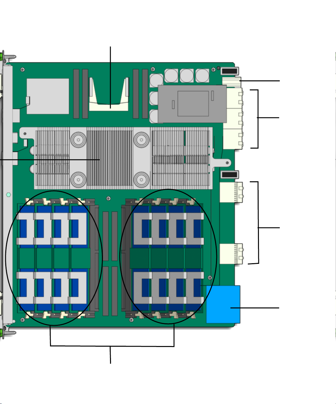
FIGURE 1-2 Netra CP3260 Blade Server (Top View)
Chapter 1 Introduction 1-5
Page 24
⑤
④
③
⑦
1-6 Netra CP3260 Blade Server User’s Guide • April 2009
②
①
Page 25
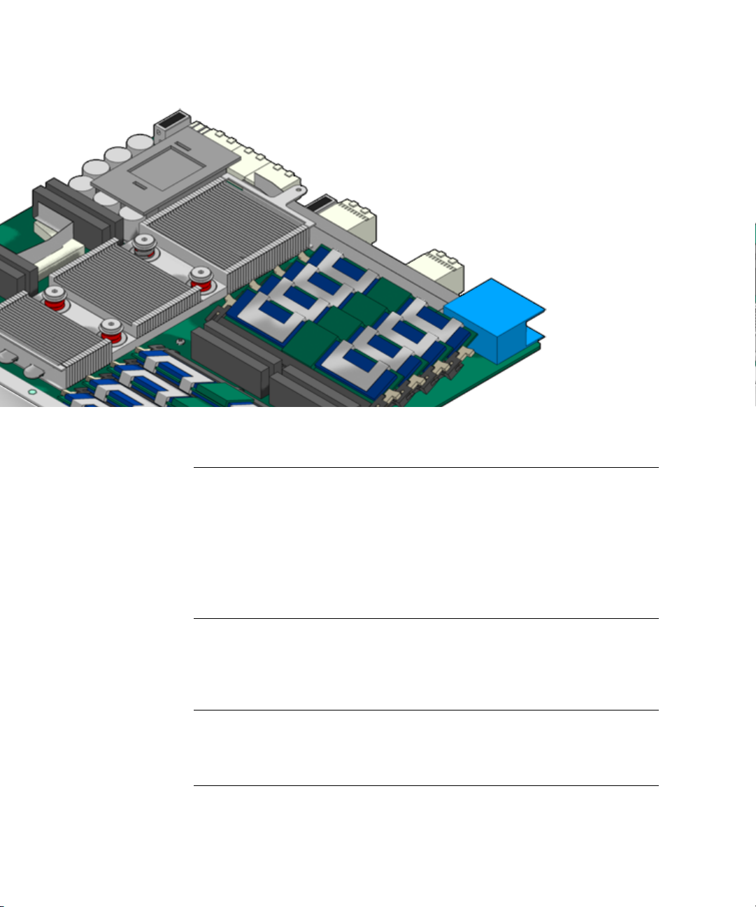
Figure Legend
1 Top latch
2 Out of Service LED (yellow)
3 Ethernet management port (RJ-45)
4 OK LED (green)
5 Dual USB Ports (USB 2.0)
6 Serial (console) port (RJ-45, ttya)
7 Hot-Swap LED (blue)
8 Hot-Swap switch and bottom latch
Figure Legend
1 Zone 1 power connector
2 Zone 2 signal connectors
3 Zone 3 RTM signal connectors
4 Zone 3 ARTM power connector
Chapter 1 Introduction 1-7
Page 26

Figure Legend
5 Compact Flash connector
6 UltraSPARC T2 processor (under heat sink)
7 FB-DIMMs
1.3 System Configurations
Netra CP3260 blade servers can be installed in an ATCA shelf (or chassis), as shown
in
FIGURE 1-3. The blade servers can be deployed in various electrical configurations
to suit each end-user requirement. For example, the blade server can be configured
to boot from a network as a diskless client with either a front panel or RTM network
connection, or from an optional Compact Flash card. Also, a Netra CP32x0 SAS
Storage ARTM, Dual HD can be installed to provide local disk I/O, which can be
used optionally as a boot path.
1-8 Netra CP3260 Blade Server User’s Guide • April 2009
Page 27

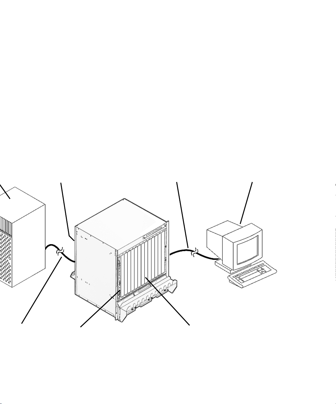
FIGURE 1-3 Netra CP3260 Blade Server in an ATCA Shelf Enclosure
Chapter 1 Introduction 1-9
Page 28
Ethernet
②
③④
⑤
1-10 Netra CP3260 Blade Server User’s Guide • April 2009
⑥⑦
Page 29

Figure Legend
1 Remote server
2 Sun Netra CP32X0 Advanced RTM (installed from rear)
3 Serial connection
4 Console terminal
5 Ethernet connection (RJ-45)
6 Sun Netra CP3260 blade server (installed from front)
7 Netra CT 900 server ATCA shelf
1.4 Advanced Rear Transition Modules
An optional Sun Netra CP32X0 Advanced Rear Transition Module (ARTM) can be
installed into the rear of the ATCA enclosure, opposite the Netra CP3260 blade
server (
server’s Zone 3 rear I/O connectors (
information on the Netra CP32x0 ARTMs.
FIGURE 1-4 shows the physical relationship between the blade server, the rear
transition module, and the midplane in a typical ATCA system.
FIGURE 1-3). The Netra CP32x0 ARTM connects to the Netra CP3260 blade
FIGURE 1-2). Contact your Sun representative for
Chapter 1 Introduction 1-11
Page 30
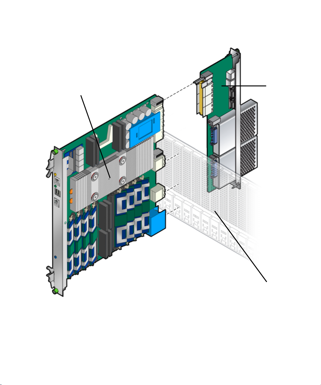
FIGURE 1-4 Netra CP3260 Blade Server, Midplane, and Netra CP32x0 ARTM
①
②
1-12 Netra CP3260 Blade Server User’s Guide • April 2009
③
Page 31

Figure Legend
1 Sun Netra CP3260 blade server
2 Sun Netra CP32X0 ARTM
3 ATCA chassis midplane
Note – When a Netra CP32x0 ARTM is used with the Netra CP3260 blade server,
shielded cables are required for serial I/O ports. Unshielded cables can be used on
Ethernet ports to satisfy EMI compliance standards. The shields for all shielded
cables must be terminated on both ends.
The customer can order a Netra CP32x0 ARTM, build a custom card, or buy from an
independent hardware vendor (IHV). A minimal set of I/O must provide a boot
path for the host blade server and a path for console I/O to deliver commands and
to read blade server and system status.
Possible boot and console configurations are described in
Microsystems supplies the Netra CP3260 blade server and compatible Netra CP32x0
ARTMs. The other configurations require (IHV) hardware.
TABLE 1-2 I/O Configurations
I/O Hardware Required Description
Ethernet Netra CP3260 blade server
Netra CP32x0 ARTM
(ARTM—supplied as an option
for rear access)
SAS Netra CP32x0 SAS Storage
ARTM, Dual HD
Serial data Netra CP3260 blade server
Netra CP32x0 ARTMs
Compact
Flash
Sun Compact Flash card The Compact Flash connector can be used to add an optional
Default boot path uses the Ethernet port; when the blade server
runs in diskless client configuration.
SAS devices can be used for local booting.
Serial port on front panel provides a path for a console I/O.
The serial port can be used on either the Netra CP3260 blade
server or Netra CP32x0 ARTM, but both ports cannot be used at
the same time. If the serial port on Netra CP3260 blade server is
used, the serial port on the Netra CP32x0 ARTMs should not be
used and vise versa.
Sun 8-Gbyte or 16-Gbyte user flash type I/II memory card.
TABLE 1-2. Sun
Chapter 1 Introduction 1-13
Page 32

1.5 Hot-Swap Support
There are three hot-swap models described in the PICMG ATCA specification: basic
hot-swap, full hot-swap, and high-availability (HA) hot-swap. Refer to the PICMG
ATCA Specification, which provides a detailed description of this subject.
The Netra CP3260 blade server supports basic hot-swap. The hot-swap process uses
hardware connection control to disconnect and connect the hardware in an orderly
sequence.
1.6 System Requirements and Options
This section contains the system-level hardware and software requirements and
options for the Netra CP3260 blade server.
1.6.1 Hardware Requirements and Options
Sun provides the following items for customer order:
■ Netra CP3260 blade server
■ The Netra CT 900 server fan tray upgrade kit (part number: 594-4953)
This upgrade kit must be installed in the Netra CT 900 server chassis to provide
adequate cooling. Refer to the Netra CT 900 Server Upgrade Guide (820-3255) for
more information. (Also see Section 2.7, “Installing the Netra CP3260 Blade
Server” on page 2-21 for fan tray upgrade verification information.)
■ (Optional) Netra CP32x0 ARTMs
An RTM enables rear system I/O access to the network, to a boot device, or to a
console terminal. The Netra CP32x0 ARTMs also provide a variety of I/O and
storage solutions, an AMC-like interface, and hot-swap capability.
The Netra CP32x0 ARTMs are optional and must be ordered separately. Contact
your Sun representative for information on the Netra CP32x0 ARTMs and
compatibility with the Netra ATCA node boards.
■ (Optional) Compact Flash card
An IDE Compact Flash card is optional and must be ordered separately.
Acquire the following components, if needed:
1-14 Netra CP3260 Blade Server User’s Guide • April 2009
Page 33

■ Serial terminal or terminal emulation for console output.
■ Cables for terminal and network connections.
■ Optional AMC disks and PCI-E cards.
The following are ATCA and other minimum requirements met by the Netra CP3260
blade server.
■ ATCA system enclosure for 8U boards (includes chassis, midplane, power supply)
■ Console output device or serial terminal
■ Boot device (such as hard drive, network, or Compact Flash card
■ Peripheral device for network access
■ Intelligent Platform Management Controller (IPMC)
1.6.2 Software Requirements
The Netra CP3260 blade server supports Solaris 10 8/07 OS and subsequent
compatible versions
Refer to the Netra CP3260 Blade Server Product Notes (820-0455) for more Solaris OS
information, including a list of the required software patches. You can view and
download the latest version of this manual at the following web site:
http://docs.sun.com/app/docs/prod/netra.brds
1.7 Technical Support and Warranty
Should you have any technical questions or support issues that are not addressed in
the Netra CP3260 blade server documentation set or on the web site, contact your
local Sun Services representative. This hardware carries a one-year return-to-depot
warranty. For customers in the US or Canada, call 1-800-USA-4SUN (1-800-872-4786).
For customers in the rest of the world, find the World Wide Solution Center nearest
you by visiting our web site:
http://www.sun.com/service/contacting/solution.html
When you call Sun Services, be sure to indicate if the Netra CP3260 blade server was
purchased separately and is not associated with a system. Have the proper blade
server identification information ready. Be prepared to give the representative the
blade server part number, serial number, and date code (
FIGURE 1-5).
Chapter 1 Introduction 1-15
Page 34

1.7.1 Part Number, Serial Number, and Revision Number Identification
The Netra CP3260 blade server part number, serial number, and revision can be
found on labels located on the card (
following information:
■ SunSN – Sun serial number (for example, 1005LCB-0626WM001M)
■ SunPN – Sun part number and dash number (for example, 501-7658-01), -01 is the
dash number
■ Rev – Revision number of the part (for example: Rev 06)
The Media Access Control (MAC) address label contains the MAC address for the
blade server in printed and barcode form.
FIGURE 1-5). The Sun barcode labels provide the
1-16 Netra CP3260 Blade Server User’s Guide • April 2009
Page 35

FIGURE 1-5 Netra CP3260 Blade Server Barcode Labeling
Note – You might find the labels shown in FIGURE 1-5 on other locations on your
blade server. Your particular blade server configuration might also appear different
than the illustration.
Chapter 1 Introduction 1-17
Page 36

1-18 Netra CP3260 Blade Server User’s Guide • April 2009
Page 37

CHAPTER
2-CHAPTER
Hardware Installation
This chapter describes the hardware installation procedures for the Netra CP3260
blade server, and contains the following sections:
■ Section 2.1, “Equipment and Operator Safety” on page 2-1
■ Section 2.2, “Materials and Tools Required” on page 2-3
■ Section 2.3, “Preparing for the Installation” on page 2-3
■ Section 2.4, “Installation Procedure Summary” on page 2-4
■ Section 2.5, “Configuring On-Board Hardware” on page 2-5
■ Section 2.6, “Installing an Advanced Rear Transition Module (Optional)” on
page 2-18
■ Section 2.8, “Connecting External I/O Cables” on page 2-23
2.1 Equipment and Operator Safety
Refer to Important Safety Information for Sun Hardware Systems (816-7190) for general
safety information.
Read the safety statements specific to the Netra CP3260 blade server carefully before
you install or remove any part of the system.
Caution – Depending on the particular chassis design, operations with open
equipment enclosures can expose the installer to hazardous voltages with a
consequent danger of electric shock. Ensure that line power to the equipment is
disconnected during operations that make high voltage conductors accessible.
2-1
Page 38

The installer must be familiar with commonly accepted procedures for integrating
electronic systems and with the general practice of Sun systems integration and
administration. Although parts of these systems are designed for hot-swap
operation, other components must not be subjected to such stresses. Work with
power connected to a chassis only when necessary, and follow these installation
procedures to avoid equipment damage.
This equipment is sensitive to damage from electrostatic discharge (ESD) from
clothing and other materials. Use the following antistatic measures during an
installation:
■ If possible, disconnect line power from the equipment chassis when servicing a
system or installing a hardware upgrade. If the chassis cannot be placed upon a
grounded antistatic mat, connect a grounding strap between the facility electrical
input ground (usually connected to the equipment chassis) and facility electrical
service ground.
■ Use an antistatic wrist strap when:
■ Removing a blade server from its antistatic bag
■ Connecting or disconnecting blade servers or peripherals
The other end of the strap lead should be connected to one of the following:
■ A ground mat
■ Grounded chassis metalwork
■ A facility electrical service ground
■ Keep blade servers in the antistatic bags until they are needed.
■ Place circuit blade servers that are out of their antistatic bags on an antistatic mat
if one is available. The mat must be grounded to a facility electrical service
ground. Do not place blade servers on top of an antistatic bag unless the outside
of the bag also has antistatic protective properties.
■ Remove a blade server from its antistatic bag only when wearing a properly
connected ground strap.
2-2 Netra CP3260 Blade Server User’s Guide • April 2009
Page 39

2.2 Materials and Tools Required
This section provides information on the materials and tools required to perform
installation. The minimum tools required to perform installation are:
■ Phillips screwdrivers, No. 1, No. 2 (optional)
■ Antistatic wrist strap
■ Terminal console
See Section 1.6.1, “Hardware Requirements and Options” on page 1-14 for
information on hardware requirements.
2.3 Preparing for the Installation
Prepare for installation by reading and performing the following steps:
1. Become familiar with the contents of the documentation referenced in the steps.
2. Verify that all listed hardware and software are available (see Section 1.6, “System
Requirements and Options” on page 1-14).
3. Check power, thermal, environmental, and space requirements (see Section 2.3.1,
“Checking Power, Thermal, Environmental, and Space Requirements” on
page 2-3).
4. Verify that local area network (LAN) preparations are completed (see
Section 3.3.3, “Determining Local Network IP Addresses and Host Names” on
page 3-7).
5. Ensure that the host names and their network IP addresses are allocated and
registered at the site.
2.3.1 Checking Power, Thermal, Environmental, and Space Requirements
Verify that you meet the following requirements:
■ Your enclosure specifications support the sum of the specified maximum blade
server power loads.
Chapter 2 Hardware Installation 2-3
Page 40

■ Facility power loading specifications can support the rack or enclosure
requirements.
■ Your enclosure specifications support the cooling airflow requirements. The Netra
CP3260 blade server fits a standard ATCA shelf or chassis. If your installation
requirements are different, contact your field application engineer.
2.4 Installation Procedure Summary
The procedure in this section summarizes the Netra CP3260 blade server installation
at a high level. Be sure to read the details in Section 2.5, “Configuring On-Board
Hardware” on page 2-5 before installing the blade server.
The procedure to set up and configure a Netra CP3260 blade server in a system
includes the following actions:
1. Configure the on-board physical hardware. For example, add memory or optional
Compact Flash.
2. Configure and install a rear transition module (RTM), if necessary.
3. Physically install the Netra CP3260 blade server into the chassis.
4. Connect the nodes to a local network. Alternatively, the blade server can be run as
a standalone system without a network connection.
5. Install the operating system and patches, as necessary. See Section 3.1, “Operating
Systems and Patches” on page 3-1.
6. Download firmware updates, if needed. See Section 3.4, “Firmware Updates” on
page 3-8.
7. Configure the operating system for 1-GbE or 10-GbE Ethernet switches. See
Section 3.5, “Configuring for 1-GbE or 10-GbE Switches” on page 3-8
2-4 Netra CP3260 Blade Server User’s Guide • April 2009
Page 41

2.5 Configuring On-Board Hardware
This section provides the procedures for adding or replacing the on-board hardware
components such as memory modules, a Compact Flash card, and the time-of day
(TOD) battery. Read and perform the procedures, as necessary, before installing the
Netra CP3260 blade server into the chassis.
2.5.1 Adding or Replacing FB-DIMM Memory Modules
The Netra CP3260 blade server supports a total of 8 FB-DIMMs and a maximum
memory capacity of 16 Gbytes (using eight 2-Gbyte DIMMs).
location of the FB-DIMMs. The Netra CP3260 blade server accommodates the
following:
■ Eight standard FB-DIMMs, buffered, and registered
■ 1-Gbyte or 2-Gbyte FB-DIMM modules
Note – You cannot mix 1-Gbyte and 2-Gbyte FB-DIMMs. All eight DIMMs must be
the same density (that is, all 1-Gbyte or all 2- Gbyte FB-DIMMs).
The Netra CP3260 blade server supports FB-DIMM memory modules that have the
following characteristics:
■ Each DIMM has a 72-bit-wide data bus (64+8 ECC) and up to 14 address bits.
■ Memory controller supports 128-bit data plus 9-bit error-correcting code (ECC).
■ Maximum of 16 Gbytes (eight 2-Gbyte FB-DIMMs) or 8 Gbyte (eight 1-Gbyte
FB-DIMMs).
■ FB-DIMM @1.55 volts or FB-DIMM@1.8 volts
FIGURE 2-1 shows the
For information about sensors, refer to the Netra CT 900 Software Developer’s Guide
(819-1175)
.
For additional information, see Section 5.2.2, “Memory Subsystem” on page 5-9.
FIGURE 2-1 shows the location of the DIMMs.
Chapter 2 Hardware Installation 2-5
Page 42

FIGURE 2-1 FB-DIMM Memory Locations
2-6 Netra CP3260 Blade Server User’s Guide • April 2009
Page 43

Chapter 2 Hardware Installation 2-7
Page 44

2-8 Netra CP3260 Blade Server User’s Guide • April 2009
Page 45

Figure Legend
FB0B DIMM
1
FB0A
2
FB1B DIMM
3
FB1A
4
Pair 0
Pair 1
FB2A DIMM
5
FB2B
6
FB3A DIMM
7
FB3B
8
Pair 2
Pair 3
Chapter 2 Hardware Installation 2-9
Page 46

2.5.1.1 To Remove FB-DIMM Memory Modules
You might need to remove a FB-DIMM module from the Netra CP3260 blade server
if you are returning the FB-DIMM module or the blade server for service, or if you
are replacing a module with another FB-DIMM module.
Note – Safely store the original factory-shipped FB-DIMM and related FB-DIMM
packaging. You might wish to store any removed FB-DIMM in the new FB-DIMM
packaging, or use the packaging for service.
To remove a FB-DIMM from the Netra CP3260 blade server, perform the following
steps:
1. Take antistatic precautions: attach and electrically ground the wrist strap.
Caution – Always wear a grounded antistatic wrist strap when handling modules.
2. Place the Netra CP3260 blade server on an antistatic mat, or on the blade
server’s antistatic bag if you do not have a mat available.
3. For the FB-DIMM you wish to remove, simultaneously pull both FB-DIMM
retainer clips outward from the slot (see
4. Grasp the FB-DIMM by the edges, and carefully pull it out of its connector (see
➋ in FIGURE 2-2). A slight rocking motion might be required.
➊ in FIGURE 2-2).
Caution – Take extra care to prevent damage when removing the outer most
FB-DIMMs.
5. Place it in an antistatic bag.
2-10 Netra CP3260 Blade Server User’s Guide • April 2009
Page 47

FIGURE 2-2 Removing an FB-DIMM Memory Module
6. If you are replacing the module you removed with a new FB-DIMM, install it
as described in Section 2.5.1.2, “To Install FB-DIMM Memory Modules” on
page 2-11.
2.5.1.2 To Install FB-DIMM Memory Modules
The following procedure provides a general guide for installing additional memory.
However, for directions on the installation process of the memory FB-DIMMs on the
Netra CP3260 blade server, refer to the documentation that shipped with the
memory module.
Caution – Do not remove the FB-DIMM from its antistatic container until you are
ready to install it on the card. Handle the module only by its edges. Do not touch
module components or metal parts. Always wear a grounded antistatic wrist strap
when handling modules.
Chapter 2 Hardware Installation 2-11
Page 48

1. Locate the FB-DIMM connectors on the Netra CP3260 blade server.
Select the connectors where you will install the memory module (
FIGURE 2-1). If
you need to replace an existing memory module with a new module, see
Section 2.5.1.1, “To Remove FB-DIMM Memory Modules” on page 2-10 for
instructions on removing the FB-DIMM module.
2. Remove the FB-DIMM from its protective packaging, holding the module only
by the edges.
3. Insert the bottom edge of the FB-DIMM into the bottom of the slot’s
hinge-style connector (see
➊ in FIGURE 2-3).
The socket and module are both keyed, which means the module can be installed
one way only. With even pressure, push simultaneously on both upper corners of
the FB-DIMM until its bottom edge (the edge with the gold fingers) is firmly
seated in the connector.
FIGURE 2-3 Installing a FB-DIMM Memory Module
Caution – Do not rock the FB-DIMM into place. Ensure that all contacts engage at
the same time. You will feel or hear a click when the FBDIMM properly seats in the
connector.
2-12 Netra CP3260 Blade Server User’s Guide • April 2009
Page 49

4. Press the top edge of the FB-DIMM toward the blade server until the retainer
clips click into place (see
The small retainer clips on each side of the FB-DIMM slot click into place in the
notches on the sides of the FB-DIMM.
➋ in FIGURE 2-3).
2.5.2 Adding or Replacing Compact Flash Card
You can install an optional Sun Compact Flash card on the Netra CP3260 blade
server. The Compact Flash card is not hot-swappable and there is no access to the
card once the blade server is installed in an ATCA chassis.
To install the Compact Flash card, use the arrow on the card’s label as a guide and
insert the card into the Compact Flash connector (
Note – On the Netra CP3260, the Compact Flash is an USB removable media device.
Therefore, you must use the Solaris rmformat utility to format the device. Refer to
the rmformat(1) man page for more information.
Note – Sun Compact Flash cards have a life of 2,000,000 write/erase cycles. Users
are responsible for ensuring that the operating system and applications do not
exceed this limitation.
FIGURE 2-4).
If the Solaris OS is installed on the Compact Flash card, Sun recommends that you
reconfigure the swap space to another storage device.
Chapter 2 Hardware Installation 2-13
Page 50

FIGURE 2-4 Compact Flash Card Location
Figure Legend
1 Compact Flash connector
2.5.3 Adding or Replacing TOD Clock Battery
FIGURE 2-5 shows the location of the TOD clock battery and holder.
The optional TOD battery must be type CR1632, with a minimum of 4ma abnormal
charging current rating (for example; a Renata CR1632).
2-14 Netra CP3260 Blade Server User’s Guide • April 2009
Page 51

Caution – Risk of explosion if the battery is replaced by an incorrect type.
Dispose of batteries properly in accordance with manufacturer’s instructions and
local regulations.
To install the battery, perform the following steps:
1. Remove the FB-DIMM closest to the front panel.
To do this, see Section 2.5.1.1, “To Remove FB-DIMM Memory Modules” on
page 2-10.
2. (Optional) Remove the old battery if necessary.
3. Slide the new battery into the holder with the side labeled “+ “ facing up.
4. Re-install the FB-DIMM.
To do this, see Section 2.5.1.2, “To Install FB-DIMM Memory Modules” on
page 2-11.
Chapter 2 Hardware Installation 2-15
Page 52

FIGURE 2-5 TOD Battery Location
2-16 Netra CP3260 Blade Server User’s Guide • April 2009
Page 53

Chapter 2 Hardware Installation 2-17
Page 54

Figure Legend
1 TOD battery location
2 Remove this FB-DIMM for access to battery
3 TOD clock battery location with FB-DIMM removed
2.6 Installing an Advanced Rear Transition Module (Optional)
For rear I/O access, a compatible RTM must be used with the Netra CP3260 blade
server.
Note – If you are using a Netra CP32x0 ARTM, refer to the appropriate Netra
CP32x0 ARTM User’s Guide for specific installation instructions.
In general, install the RTM from the rear of the server. Look at the front of the server
and locate the slot number where the Netra CP3260 blade server is installed. Then
go to the back of the server and install the RTM in that particular slot.
2-18 Netra CP3260 Blade Server User’s Guide • April 2009
Page 55

FIGURE 2-6 Installing a Netra CP32X0 ARTM
②
①
③
Figure Legend
1 Netra CP3260 blade server
2 Netra CP32X0 ARTM
3 ATCA chassis midplane
Chapter 2 Hardware Installation 2-19
Page 56

2.7 Installing the Netra CP3260 Blade Server
Caution – The Netra CT 900 server fan tray upgrade kit (594-4953) must be
installed in the chassis before the Netra CP3260 blade server is installed. This fan
tray upgrade is required to provide adequate cooling and to prevent the system from
overheating or shutting down due to an over-temperature condition that can occur
with the older fan trays.
To verify that the fan tray upgrade is installed on a Netra CT 900 server, log into the
Shelf Manager and issue the following command for fan trays 1, 2, and 3 (or fan
trays 0, 1, and 2 for older chassis):
clia fruinfo fan_tray 1 | grep "Product Part"
If Product Part / Model Number = 371-3033-xx is displayed, an upgraded
fan tray is installed. If Product Part / Model Number is not 371-3033, an old fan
tray is installed and the upgrade is required. Refer to the Netra CT 900 Server Upgrade
Guide (820-3255) for more information.
To Install the Netra CP3260 blade server, perform the following steps:
1. If you have installed a Netra CP32x0 ARTM, go to the front of the system and
locate the card slot where you installed the ARTM at the rear of the system.
2. Remove the filler panel, if necessary.
The filler panel is secured to the card cage using two screws, one at the top of the
filler panel, the other at the bottom. Store the filler panel in a safe place; you
might need to use it again if you have to remove a card for an extended period of
time.
3. Prepare the blade server by opening the injector/ejector latches (
4. Carefully align the edges of the blade server with the card guides in the
appropriate slot (
It might be helpful to look into the enclosure to verify correct alignment of the
rails in the guides.
5. Taking care to keep the blade server aligned in the guides, slide the blade
server in until the injector/ejector latches engage the card cage.
2-20 Netra CP3260 Blade Server User’s Guide • April 2009
FIGURE 2-7).
FIGURE 2-8).
Page 57

FIGURE 2-7 Installing Blade Server Into Chassis Slot
6. Push the blade server slightly into the midplane connectors, and then close the
latches to seat the blade server in the connectors (
FIGURE 2-8).
7. When the lower latch is closed, the blue Hot-Swap LED blinks while the blade
server is initializing. The blue LED turns off and the green OK LED lights when
the blade server is ready.
8. Tighten the locking screws to ensure the blade server is secured into the shelf
(
FIGURE 2-8).
Chapter 2 Hardware Installation 2-21
Page 58

FIGURE 2-8 Netra CP3260 Blade Server Latches and Locking Screws
2.8 Connecting External I/O Cables
External I/O cables are connected to the Netra CP3260 blade server, or to the Netra
CP32x0 ARTM when a rear transition module is used.
2-22 Netra CP3260 Blade Server User’s Guide • April 2009
Page 59

Note – Shielded cables are required for serial I/O ports. Unshielded cables can be
used on Ethernet ports to satisfy EMI compliance standards. The shields for all
shielded cables must be terminated on both ends.
Information on connecting each of these cables follows:
■ For Ethernet connections, category 5e or better network cable is required. One
end of the Ethernet cable is connected to a suitable 10/100/1000BASE-T switch
and the other end to one of the Ethernet ports on the Netra CP3260 blade server.
A single 10/100BASE-T Ethernet port is also available on a Netra CP32x0 ARTM
when installed. Refer to the appropriate Netra CP32x0 ARTM User’s Guide for
more information.
Use the Ethernet device names shown in
TABLE 2-1 when configuring the Ethernet
ports.
TABLE 2-1 Ethernet Device Names
Ethernet Ports
Ethernet management port (on front panel) e1000g4
■ A shielded asynchronous serial I/O cable can be attached from serial
Solaris 10 OS
Device Name
communication devices to the RJ-45 serial port on the Netra CP3260 blade
server’s front panel.
A serial port is also provided on the Netra CP32x0 ARTM. You can use either the
serial port on the Netra CP3260 blade server or the serial port on Netra CP32x0
ARTM, but only one of the ports should be used at one time.
Once a serial cable is connected, use the tip utility on the host to establish a
full-duplex terminal connection with the Netra CP3260 blade server.
At the UNIX prompt in a command tool or shell tool, type:
# tip -9600 /dev/ttya (for serial port)
■ USB 2.0 cables can be attached from USB devices to the dual USB 2.0-compliant
ports on the Netra CP3260 blade server’s front panel.
Chapter 2 Hardware Installation 2-23
Page 60

2.9 Hot-Swapping the Netra CP3260 Blade Server
The Netra CP3260 blade server supports hot-swapping at the blade server level.
Note – Before hot-swapping the blade server, the system administrator should
gracefully shutdown the applications and operating system, and deactivate the
blade server. After the blade server is replaced, the system administrator should
activate the new blade server.
The blue Hot-Swap LED, located on the front panel of the Netra CP3260 blade server
FIGURE 1-1), blinks when a hot-swap is initiated, and lights steadily when the blade
(
server is ready to be removed from the system.
Unlatching the bottom latch on the Netra CP3260 blade server initiates the hot-swap
sequence. The LED lights steadily when the blade server can be safely removed from
the system. The reverse is true when a Netra CP3260 blade server is installed into
the system. Once the Netra CP3260 blade server is installed into the system and the
bottom latch is latched, the blue Hot-Swap LED blinks until the blade server is ready
and then turns off. The green LED lights steadily when the blade server is ready.
FIGURE 2-9 shows the hot-swap latch and Hot-Swap LED.
2-24 Netra CP3260 Blade Server User’s Guide • April 2009
Page 61

FIGURE 2-9 Hot-Swap Latch and Hot-Swap LED
Chapter 2 Hardware Installation 2-25
Page 62

2-26 Netra CP3260 Blade Server User’s Guide • April 2009
Page 63

CHAPTER
3-CHAPTER
Software Installation
This chapter contains the following sections:
■ Section 3.1, “Operating Systems and Patches” on page 3-1
■ Section 3.2, “Configuring Payload OS NIU Driver for Multiplexing to Zones 2 and
3” on page 3-2
■ Section 3.3, “Installing as a Diskless Clients” on page 3-4
■ Section 3.4, “Firmware Updates” on page 3-8
■ Section 3.5, “Configuring for 1-GbE or 10-GbE Switches” on page 3-8
■ Section 3.6, “Downloading and Installing SunVTS Software” on page 3-9
■ Section 3.7, “Formatting the Optional Compact Flash Card” on page 3-10
3.1 Operating Systems and Patches
The Sun Netra CP3260 blade server uses the Solaris 10 8/07 OS and subsequent
compatible versions, with associated patches. Refer to the Netra CP3260 Blade Server
Product Notes (820-0455) for the Solaris OS version and the patches and patch
installation procedures. Theses notes are available online at:
http://docs.sun.com/app/docs/prod/netra.brds
The Solaris OS software and patches can be downloaded from SunSolve
Download Center (SDLC) at:
http://www.sun.com/download
Note – For information on versions of the Solaris OS, including installation, see the
appropriate Solaris Documentation Collection at the Sun Documentation web site at
http://docs.sun.com/app/docs/prod/solaris.
SM
or the Sun
3-1
Page 64

Depending the blade server’s hardware configuration, the Sun Netra CP3260 blade
server can be used as a diskless client with the Solaris OS installed on a boot server
(see Section 3.3, “Installing as a Diskless Clients” on page 3-4. The OS can also be
downloaded to a boot device like the Netra CP32x0 SAS Storage ARTM, Dual HD, or
an optional Compact Flash.
3.2 Configuring Payload OS NIU Driver for Multiplexing to Zones 2 and 3
The MUX configuration by system management software and payload driver
configuration must be in sync for proper functioning of both 10Gbps Ethernet
(nxge) interfaces. The payload driver relies on the driver configuration file
(nxge.conf) to initialize interfaces to either Zone 2 (backplane) or Zone 3 (ARTM).
The driver uses phy-type property to configure each interface. On the Netra
CP3260 blade server, the phy-type can have the following values:
■ phy-type=gsd (for interface to operate at 1Gbps with Zone 2 connectivity)
■ phy-type=xgsd (for interface to operate at 10Gbps with Zone 2 connectivity)
■ phy-type=xgf (for interface to operate at 10Gbps with Zone 3 connectivity)
For default installations, the nxge driver is in the /platform/sun4v/kernel/drv
directory.
The following examples show how to configure zone/link speed in the nxge driver
file for Zone 2 and Zone 3 connectivity when using the Solaris OS.
CODE EXAMPLE 3-1 Zone 2 Connectivity (Both nxge Ports)
name = "SUNW,niusl" parent = "/niu@80" unit-address = "0" phy-type
= "gsd";
name = "SUNW,niusl" parent = "/niu@80" unit-address = "1" phy-type
= "xgsd";
Note – The phy-type=”gsd” sets the interface at 1Gbps and the phy-type=
”xgsd” sets the interface at 10Gbps.
CODE EXAMPLE 3-2 Zone 3 Connectivity (Both nxge Ports)
name = "SUNW,niusl" parent = "/niu@80" unit-address = "0" phy-type
= "xgf";
name = "SUNW,niusl" parent = "/niu@80" unit-address = "1" phy-type
= "xgf";
3-2 Netra CP3260 Blade Server User’s Guide • April 2009
Page 65

CODE EXAMPLE 3-3 Zone 2 and Zone 3 Connectivity: First NIU Port (nxge0) to Zone 2
(at 10Gbps Speed) and the Second NIU Port (nxge1) to Zone3
name = "SUNW,niusl" parent = "/niu@80" unit-address = "0" phy-type
= "xgsd";
name = "SUNW,niusl" parent = "/niu@80" unit-address = "1" phy-type
= "xgf";
CODE EXAMPLE 3-4 Zone 2 and Zone 3 Connectivity: First NIU Port (nxge0) to Zone 3
(at 10Gbps Speed) and the Second NIU Port (nxge1) to Zone2
name = "SUNW,niusl" parent = "/niu@80" unit-address = "0" phy-type
= "xgf";
name = "SUNW,niusl" parent = "/niu@80" unit-address = "1" phy-type
= "xgsd";
Chapter 3 Software Installation 3-3
Page 66

3.3 Installing as a Diskless Clients
The following procedures describe how to create a boot server for diskless clients
and how to add new diskless clients to the patched boot server. For additional
instructions on installing diskless clients, refer to the appropriate Solaris
Documentation Collection at the Sun Documentation web site at:
http://docs.sun.com/app/docs/prod/solaris
You must have a superuser password on your diskless server to perform the tasks in
the following sections.
3.3.1 Creating a Boot Server for Diskless Clients
This procedure sets up a boot server by starting the operating environment services
required for diskless clients. Once you have set up the boot server, see Section 3.3.2,
“Adding a Diskless Client” on page 3-5 for instructions on adding diskless clients to
the boot server.
To create a boot server for diskless clients:
1. Verify that the IP addresses for all other network interfaces on the boot server
have corresponding host names in the hosts database.
2. Log in to the network server as superuser and change to the /usr/sadm/bin
directory.
# cd /usr/sadm/bin
3. Use the smosservice command to add boot services to the installation server.
Note – The \ (backslash) in the following code boxes is a line-continuation character
indicating that the command is continued on the next line.
# ./smosservice add -u root -p root_password -- -x mediapath=image_directory \
-x platform=sparc.sun4v.Solaris_n -x cluster=SUNWCXall -x locale=locale
Where:
■ root_password is the root password for the installation server
■ image_directory is the path to the directory where the Solaris install image is stored
■ n is the Solaris OS version you are using.
3-4 Netra CP3260 Blade Server User’s Guide • April 2009
Page 67

■ locale is the locale that you want to use
■ \ (backslash) is a line-continuation character indicating that the command is
continued on the next line.
Refer to the smosservice(1M) man page for more information and options.
For example:
# ./smosservice add -u root -p root_password -- -x mediapath=/export/install \
-x platform=sparc.sun4v.Solaris_10 -x cluster=SUNWCXall -x locale=en_US
Where:
■ root_password = root_password
■ image_directory = /export/install
■ locale = en_US
■ n = 10 (for Solaris 10)
■ \ (backslash) is a line-continuation character indicating that the command is
continued on the next line.
4. Download and install additional patches.
Refer to the Netra CP3260 Blade Server Product Notes (820-0455) for the latest
information on the patches available for the Sun Netra CP3260 blade server. The
document can be downloaded from the following web site:
http://docs.sun.com/app/docs/prod/netra.brds
Follow the instructions in the Netra CP3260 Blade Server Product Notes (820-0455)
for downloading and applying patches to a diskless clients boot server.
5. After the patches are installed, follow the procedure in Section 3.3.2, “Adding a
Diskless Client” on page 3-5.
3.3.2 Adding a Diskless Client
1. Prepare a patched boot server for the diskless clients.
Follow the steps in Section 3.3.1, “Creating a Boot Server for Diskless Clients” on
page 3-4 to create a boot server for the diskless clients.
2. Log in to the patched boot server as superuser.
3. Collect the following information for the diskless client you are adding:
■ Client’s IP address
■ Client’s Ethernet address
■ Client’s host name
Chapter 3 Software Installation 3-5
Page 68

4. Change directories to the /usr/sadm/bin directory.
# cd /usr/sadm/bin
5. Set up the diskless clients.
For each diskless client, type the following command as superuser:
# ./smdiskless add -- -i ip_address -e ethernet_address -n host_name \
-x os=sparc.sun4v.Solaris_n -x root=/export/root/host_name \
-x swap=/export/swap/host_name -x swapsize=swap_size -x tz=time_zone \
-x locale=locale -x ns=name_service -x nameserver=name_server
Where:
■ ip_address is the client’s IP address
■ ethernet_address is the client’s Ethernet address
■ host_name is the client’s host name
■ n is the Solaris OS version you are using
■ swap_size is the size of the swap space that you will be using. The default is 24,
however your swap space should be the same amount as your memory
■ time_zone is the client’s time zone
■ locale is the client’s locale
■ name_service is the client’s nameservice
■ name_server is the nameserver ’s hostname
■ \ (backslash) is a line-continuation character indicating that the command is
continued on the next line.
Refer to the smdiskless(1M) man page for more information and options.
For example:
# ./smdiskless add -- -i 129.144.214.99 -e 8:0:20:22:b3:aa -n client_host \
-x os=sparc.sun4v.Solaris_10 -x root=/export/root/client_host \
-x swap=/export/swap/client_host -x swapsize=999 -x tz=US/Pacific \
-x locale=en_US -x ns=NIS -x nameserver=nameserver_host
Where:
■ ip_address = 129.144.214.99
■ ethernet_address = 8:0:20:22:b3:aa
■ host_name = client_host
■ n = 10 (for Solaris 10)
■ swap_size = 128
3-6 Netra CP3260 Blade Server User’s Guide • April 2009
Page 69

■ time_zone = US/Pacific
■ locale = en_US
■ name_service = NIS
■ name_server = nameserver_host
■ \ (backslash) is a line continuation character indicating that the command is
continued on the next line.
You must type your superuser password again after typing this command. The
installation process should take roughly 5 minutes per client and about 15-30
minutes for the operating environment service to install; however, no progress is
displayed on screen while the process is running. Do not cancel or kill the process
until the process has successfully completed.
You should see messages similar to the following after a few minutes, confirming
that the command went through successfully the second time:
Login to client_host as user root was successful.
Download of com.sun.admin.osservermgr.cli.OsServerMgrCli from client_host was
successful.
6. Boot the diskless client.
3.3.3 Determining Local Network IP Addresses and Host Names
Collect the following information to connect hosts to the local area network (LAN).
Ask your network administrator for help, if necessary. You can use
record this information. This information is not needed for a standalone installation.
TABLE 3-1 Local Network Information
Information Needed Your Information
IP address*and host name for each Sun
Netra CP3260 client
Domain name
Type of name service and corresponding
name server names and IP addresses—for
example, DNS and NIS (or NIS+)
Subnet mask
TABLE 3-1 to
Chapter 3 Software Installation 3-7
Page 70

TABLE 3-1
Information Needed Your Information
Gateway router IP address
NFS server names and IP addresses
Web server URL
* Local IP addresses are not needed if they are assigned by a network DHCP server.
Local Network Information
You might need the MAC (Ethernet) addresses of the local hosts to make nameserver
database entries. The MAC address can be seen in the console output while booting
to the ok prompt. It can also be derived from the host ID seen on the barcode label
(see Section 1.7.1, “Part Number, Serial Number, and Revision Number
Identification” on page 1-16).
3.4 Firmware Updates
For information on firmware updates, refer to the Netra CP3260 Blade Server Product
Notes (820-0455) which is available online at:
http://docs.sun.com/app/docs/prod/netra.brds
All Sun Netra CP3260 firmware updates can be downloaded from the Sun
Download Center (SDLC) at:
http://www.sun.com/download
3.5 Configuring for 1-GbE or 10-GbE Switches
The Fabric interface on the Sun Netra CP3260 blade server is capable of operating at
either 1 Gbps or 10 Gbps. The Sun Netra CP3260 can be used in the Netra CT 900
server with either the Sun Netra CP3240 10-GbE switch board or the Sun Netra
CP3140 1-GbE switch board. Therefore it is important that the Solaris driver
configuration file be configured accordingly on the Netra CP3260 blade server.
3-8 Netra CP3260 Blade Server User’s Guide • April 2009
Page 71

The NIU (Network Interface Unit) driver configuration file, nxge.conf, might need
to be modified to employ the proper port configurations. The nxge.conf file is
located in the /platform/sun4v/kernel/drv directory. The following examples
show the proper entries for each switch configuration. These entries are additional to
any other configuration parameters set in the nxge.conf file.
Example 1: If Sun Netra CP3240 10-GbE switches are used in Slot 7 and Slot 8, the
nxge.conf file should have the following entries:
name = "SUNW,niusl" parent = "/niu@80" unit-address = "0" phy-type = "xgsd";
name = "SUNW,niusl" parent = "/niu@80" unit-address = "1" phy-type = "xgsd";
Example 2: If Sun Netra CP3140 1-GbE switches are used in Slot 7 and Slot 8, the
nxge.conf file should have the following entries:
name = "SUNW,niusl" parent = "/niu@80" unit-address = "0" phy-type = "gsd";
name = "SUNW,niusl" parent = "/niu@80" unit-address = "1" phy-type = "gsd";
Example 3: If a Sun Netra CP3140 1-GbE switch is used in Slot 7 and a Sun Netra
CP3240 10-GbE switch in Slot 8, the nxge.conf file should have the following
entries:
name = "SUNW,niusl" parent = "/niu@80" unit-address = "0" phy-type = "gsd";
name = "SUNW,niusl" parent = "/niu@80" unit-address = "1" phy-type = "xgsd";
Example 4: If a Sun Netra CP3240 10-GbE switch is used in Slot 7 and a Sun Netra
CP3140 1-GbE switch is used in Slot 8, the nxge.conf file should have the
following entries:
name = "SUNW,niusl" parent = "/niu@80" unit-address = "0" phy-type = "xgsd";
name = "SUNW,niusl" parent = "/niu@80" unit-address = "1" phy-type = "gsd";
3.6 Downloading and Installing SunVTS Software
Sun Validation Test Suite (SunVTS™) software is a comprehensive suite that tests
and validates the Sun Netra CP3260 blade server by verifying the configuration and
function of most hardware controllers and devices on the blade server.
Chapter 3 Software Installation 3-9
Page 72

SunVTS software is used to validate a system during development, production,
inspection, troubleshooting, periodic maintenance, and system or subsystem
stressing. SunVTS software can be tailored to run on machines ranging from
desktops to servers with modifiable test instances and processor affinity features.
You can perform high-level system testing by using the appropriate version of
SunVTS software. For detailed information on SunVTS support, documentation, and
downloads, refer to the following web site:
http://www.sun.com/oem/products/vts/
You will be prompted for your Sun Online Account name and password.
For the Sun Netra CP3260 blade server, use the SunVTS6.4ps2 SPARC (or newer),
Toolkit and Documentation.
Ensure that the SunVTS software version is compatible with the Solaris OS being
used. You can find information about the SunVTS software version installed on your
system by viewing the content of the .version file:
# cat /opt/SUNWvts/bin/.version
Note – For security reasons, only a superuser is permitted to run SunVTS software.
Installation and starting instructions are included with the software when it is
downloaded.
3.7 Formatting the Optional Compact Flash Card
The Compact Flash card is an USB removable media device on the Sun Netra CP3260
blade server. Therefore, the Solaris OS rmformat utility must be used to format the
device. The Solaris OS also provides a removable media framework for use with this
type of device.
Refer to the rmformat(1) man page for more information.
3-10 Netra CP3260 Blade Server User’s Guide • April 2009
Page 73

CHAPTER
4-CHAPTER
Firmware and Blade Server Management
This chapter contains the following sections:
■ Section 4.1, “System Firmware” on page 4-2
■ Section 4.2, “Power-On Self-Test Diagnostics” on page 4-3
■ Section 4.3, “OpenBoot Firmware” on page 4-4
■ Section 4.4, “Error Handling Summary” on page 4-15
■ Section 4.5, “Automatic System Recovery” on page 4-16
■ Section 4.6, “Network Device Aliases” on page 4-18
■ Section 4.7, “Retrieving Device Information” on page 4-19
■ Section 4.8, “Multiplexing to Zones 2 and 3” on page 4-27
4-1
Page 74

4.1 System Firmware
The Netra CP3260 blade server contains a modular firmware architecture that gives
you latitude in controlling boot initialization. You can customize the initialization,
test the firmware, and even enable the installation of a custom operating system.
This platform also employs the Intelligent Platform Management Controller
(IPMC)—described in Section 5.2.8, “Intelligent Platform Management Controller”
on page 5-13—which controls the system management, hot-swap control, and some
board hardware. The IPMC configuration is controlled by separate firmware.
The Netra CP3260 blade server boots from the 4-Mbyte system flash PROM device
that includes the power-on self-test (POST) and OpenBoot™ firmware.
A systems firmware progress sensor (SFPS) is available on the Sun Netra CP3260
blade server. The purpose of the sensor is to model the firmware running on the
payload and provide various states to the external management software (ShMM on
Netra CT 900 servers). This occurs via a standard IPMI event mechanism.
The firmware states are Progress, Hang, and Error, with various substates. The
sensor generates an IPMI event message for each state. You can verify the messages
by using clia sel command on the ShMM, through HPI event and SNMP traps for
each state of a sensor event.
For more information, see Section B.4, “Send Sensor State Command” on
page B-5.
For detailed sensor command syntax and options, refer to the Netra CT 900 Software
Developer’s Guide (819-1178). (Even if you are using a third-party chassis, the SFPS
commands and options apply, and this document is available online.)
http://docs.sun.com/app/docs/prod/n900.srvr#hic
4-2 Netra CP3260 Blade Server User’s Guide • April 2009
Page 75

4.2 Power-On Self-Test Diagnostics
Power-on self-test (POST) is a firmware program that helps determine whether a
portion of the system has failed. POST verifies the core functionality of the system,
including the CPU modules, motherboard, memory, and some on-board I/O devices.
The software then generates messages that can be useful in determining the nature
of a hardware failure. POST can run even if the system is unable to boot.
If POST detects a faulty component, it is disabled automatically, preventing faulty
hardware from potentially harming any software. If the system is capable of running
without the disabled component, the system boots when POST is complete. For
example, if one of the processor cores is deemed faulty by POST, the core is disabled,
and the system boots and runs using the remaining cores.
POST diagnostic and error message reports are displayed on a console.
4.2.1 POST Test Coverage
The POST diagnostics include the following tests:
CPU Basic Test
CPU Functional Test
CPU D-Cache RAM
CPU D-Cache Tags
CPU I-Cache RAM Test
CPU I-Cache Tag RAM
CPU L2 Cache UA Array Test
CPU L2 Cache UA Array Test
CPU Interrupt Handler
CPU IMMU Memory Management Unit
CPU DMMU Memory Management Unit
FPU (Data movement and functionality)
I/O Controller register access
I/O Controller PCI configuration access
Block Memory Test
Network Interfaces (register access and basic funtionality)
Modular Arithemetic Memory parity errors Test
SPU (Security Processing Unit) Tests
Chapter 4 Firmware and Blade Server Management 4-3
Page 76

4.2.2 POST Diagnostic and Error Message Format
POST diagnostic and error messages are displayed on a console. The format of the
these messages is the following:
Core-ID:Strand-ID ERROR: TEST = test-name
Core-ID:Strand-ID H/W under test = description
Core-ID:Strand-ID Repair Instruction
Core-ID:Strand-ID MSG = error-message-body
Core-ID:Strand-ID END_ERROR
The following is an example of a POST error message
3:2>ERROR: TEST = L2-Cache Functional
3:2>H/W under test = Core l2 Cache
3:2>Repair Instructions: Replace items in order listed by ’H/W
under test’ above.
3:2>MSG = No way found to match tag address 00000000.00600000,
state 3
3:2>END_ERROR
4.3 OpenBoot Firmware
The Solaris OS installed operates at different run levels. For a full description of run
levels, refer to the Solaris system administration documentation.
Most of the time, the OS operates at run level 2 or run level 3, which are multiuser
states with access to full system and network resources. Occasionally, you might
operate the system at run level 1, which is a single-user administrative state.
However, the lowest operational state is run level 0.
When the OS is at run level 0, the ok prompt appears. This prompt indicates that the
OpenBoot firmware is in control of the system.
There are a number of scenarios under which OpenBoot firmware control can occur.
By default, before the operating system is installed, the system comes up under
OpenBoot firmware control.
■ When the auto-boot? OpenBoot configuration variable is set to false, the system
boots to the ok prompt.
■ When the operating system is halted, the system transitions to run level 0 in an
orderly way.
4-4 Netra CP3260 Blade Server User’s Guide • April 2009
Page 77

■ When the operating system crashes, the system reverts to OpenBoot firmware
control.
■ During the boot process, when there is a serious hardware problem that prevents
the operating system from running, the system reverts to OpenBoot firmware
control.
■ When a serious hardware problem develops while the system is running, the
operating system transitions smoothly to run level 0.
■ When the OS is deliberately placed under the OpenBoot firmware control in order
to execute firmware-based commands.
4.3.1 Getting to the ok Prompt
There are different ways of reaching the ok prompt. The methods are not equally
desirable. See
TABLE 4-1 Ways of Accessing the ok Prompt
Access Method What to Do
Graceful shutdown of
the Solaris OS
Manual system reset Setting the OBP
TABLE 4-1 for details.
From a shell or command tool window, issue an appropriate
command (for example, the
described in Solaris system administration documentation.
to stop at the
auto-boot variable to false causes the system
ok? prompt the next time the blade server is reset.
shutdown or init command) as
Caution – Obtaining the ok prompt suspends all application and operating system
software. After you issue firmware commands and run firmware-based tests from
the ok prompt, the system might not be able to resume where it left off.
If possible, back up system data before starting to access the ok prompt. Also exit or
stop all applications, and warn users of the impending loss of service. For
information about the appropriate backup and shutdown procedures, see Solaris
system administration documentation.
Chapter 4 Firmware and Blade Server Management 4-5
Page 78

4.3.2 Auto-Boot Options
The system firmware stores a configuration variable called auto-boot?, which
controls whether the firmware will automatically boot the operating system after
each reset. The default setting for Sun platforms is true.
Normally, if a system fails power-on diagnostics, auto-boot? is ignored and the
system does not boot unless an operator boots the system manually. An automatic
boot is generally not acceptable for booting a system in a degraded state. Therefore,
the Netra CP3260 server OpenBoot firmware provides a second setting,
auto-boot-on-error?. This setting controls whether the system will attempt a
degraded boot when a subsystem failure is detected. Both the auto-boot? and
auto-boot-on-error? switches must be set to true to enable an automatic
degraded boot. To set the switches, type:
{0} ok setenv auto-boot? true
{0} ok setenv auto-boot-on-error? true
Note – The default setting for auto-boot-on-error? is false. The system will
not attempt a degraded boot unless you change this setting to true. In addition, the
system will not attempt a degraded boot in response to any fatal nonrecoverable
error, even if degraded booting is enabled. For examples of fatal nonrecoverable
errors, see Section 4.3.4, “OpenBoot Configuration Variables” on page 4-12.
4.3.3 OpenBoot Commands
You type the OpenBoot commands at the ok prompt. The OpenBoot commands that
can provide useful diagnostic information include:
■ probe-scsi and probe-scsi-all
■ probe-ide
■ show-devs
For a complete list of OpenBoot commands and more information about the
OpenBoot firmware, refer to the OpenBoot 4.x Command Reference Manual. An online
version of the manual is included with the OpenBoot Collection AnswerBook that
ships with Solaris software.
4-6 Netra CP3260 Blade Server User’s Guide • April 2009
Page 79

4.3.3.1 probe-scsi and probe-scsi-all Commands
The probe-scsi and probe-scsi-all commands diagnose problems with the
SCSI devices.
Caution – If you used the halt command or the Stop-A key sequence to reach the
ok prompt, issuing the probe-scsi or probe-scsi-all command can hang the
system.
The probe-scsi command communicates with all SCSI devices connected to
on-board SCSI controllers. The probe-scsi-all command also accesses devices
connected to any host adapters installed in PCI slots.
For any SCSI device that is connected and active, the probe-scsi and
probe-scsi-all commands display its loop ID, host adapter, logical unit number,
unique worldwide name (WWN), and a device description that includes type and
manufacturer.
The following sample output is from the probe-scsi-all command with a Netra
CP32x0 ARTM connected to the Netra CP3260 blade server.
CODE EXAMPLE 4-1 probe-scsi-all Command Output
{0} ok probe-scsi-all
This command may hang the system if a Stop-A or halt command
has been executed. Please type reset-all to reset the system
before executing this command.
Do you wish to continue? (y/n) y
/pci@0/pci@0/pci@a/pci@0/usb@4,2/storage@2
Unit 0 Disk TUSB6250USB20 DISK DRIVE
/pci@0/pci@0/pci@8/scsi@0
MPT Version 1.05, Firmware Version 1.22.01.00
Target 2
Unit 0 Disk SEAGATE ST914602SSUN146G0400 286739329 Blocks, 146 GB
SASAddress 5000c5000576b0e5 PhyNum 7
Target 3
Unit 0 Disk SEAGATE ST914602SSUN146G0400 286739329 Blocks, 146 GB
SASAddress 5000c50005d16415 PhyNum 6
{0} ok
Chapter 4 Firmware and Blade Server Management 4-7
Page 80

4.3.3.2 probe-ide Command
The probe-ide command communicates with all Integrated Drive Electronics (IDE)
devices connected to the IDE bus. This is the internal system bus for media devices
such as the DVD drive.
Caution – If you used the halt command or the Stop-A key sequence to reach the
ok prompt, issuing the probe-ide command can hang the system.
The following shows sample output from the probe-ide command.
CODE EXAMPLE 4-2 probe-ide Command Output
{0} ok probe-ide
Device 0 ( Primary Master )
ATA Model: FUJITSU MHV2040BH
Device 1 ( Primary Slave )
ATA Model:
Device 2 ( Secondary Master )
Not Present
Device 3 ( Secondary Slave )
Not Present
4.3.3.3 show-devs Command
The show-devs command lists the hardware device paths for each device in the
firmware device tree. The following shows some sample output.
CODE EXAMPLE 4-3 show-devs Command Output
{0} ok show-devs
/pci-performance-counters@0
/ebus@c0
/pci@0
/niu@80
/cpu@3f
/cpu@3e
/cpu@3d
/cpu@3c
/cpu@3b
/cpu@3a
/cpu@39
/cpu@38
4-8 Netra CP3260 Blade Server User’s Guide • April 2009
Page 81

CODE EXAMPLE 4-3 show-devs Command Output
/cpu@37
/cpu@36
/cpu@35
/cpu@34
/cpu@33
/cpu@32
/cpu@31
/cpu@30
/cpu@2f
/cpu@2e
/cpu@2d
/cpu@2c
/cpu@2b
/cpu@2a
/cpu@29
/cpu@28
/cpu@27
/cpu@26
/cpu@25
/cpu@24
/cpu@23
/cpu@22
/cpu@21
/cpu@20
/cpu@1f
/cpu@1e
/cpu@1d
/cpu@1c
/cpu@1b
/cpu@1a
/cpu@19
/cpu@18
/cpu@17
/cpu@16
/cpu@15
/cpu@14
/cpu@13
/cpu@12
/cpu@11
/cpu@10
/cpu@f
/cpu@e
/cpu@d
/cpu@c
/cpu@b
/cpu@a
/cpu@9
Chapter 4 Firmware and Blade Server Management 4-9
Page 82

CODE EXAMPLE 4-3 show-devs Command Output
/cpu@8
/cpu@7
/cpu@6
/cpu@5
/cpu@4
/cpu@3
/cpu@2
/cpu@1
/cpu@0
/virtual-devices@100
/virtual-memory
/memory@m0,8000000
/aliases
/options
/openprom
/chosen
/packages
/ebus@c0/serial@0,ca0000
/pci@0/pci@0
/pci@0/pci@0/pci@a
/pci@0/pci@0/pci@9
/pci@0/pci@0/pci@8
/pci@0/pci@0/pci@2
/pci@0/pci@0/pci@1
/pci@0/pci@0/pci@a/pci@0
/pci@0/pci@0/pci@a/pci@0/usb@4,2
/pci@0/pci@0/pci@a/pci@0/usb@4,1
/pci@0/pci@0/pci@a/pci@0/usb@4
/pci@0/pci@0/pci@a/pci@0/usb@4,2/storage@2
/pci@0/pci@0/pci@a/pci@0/usb@4,2/storage@2/disk
/pci@0/pci@0/pci@9/network@0,1
/pci@0/pci@0/pci@9/network@0
/pci@0/pci@0/pci@8/scsi@0
/pci@0/pci@0/pci@8/scsi@0/disk
/pci@0/pci@0/pci@8/scsi@0/tape
/pci@0/pci@0/pci@2/network@0,1
/pci@0/pci@0/pci@2/network@0
/pci@0/pci@0/pci@1/network@0,1
/pci@0/pci@0/pci@1/network@0
/niu@80/network@1
/niu@80/network@0
/virtual-devices@100/rtc@5
/virtual-devices@100/console@1
/virtual-devices@100/flashprom@0
/virtual-devices@100/random-number-generator@e
/virtual-devices@100/ncp@6
/virtual-devices@100/n2cp@7
4-10 Netra CP3260 Blade Server User’s Guide • April 2009
Page 83

CODE EXAMPLE 4-3 show-devs Command Output
/virtual-devices@100/channel-devices@200
/virtual-devices@100/channel-devices@200/virtual-channel-client@1
/virtual-devices@100/channel-devices@200/virtual-channel@0
/virtual-devices@100/channel-devices@200/virtual-channel-client@2
/virtual-devices@100/channel-devices@200/virtual-channel@3
/openprom/client-services
/packages/obp-tftp
/packages/kbd-translator
/packages/SUNW,asr
/packages/dropins
/packages/terminal-emulator
/packages/disk-label
/packages/deblocker
/packages/SUNW,builtin-drivers
4.3.3.4 Using watch-net and watch-net-all Commands to Check the Network
The watch-net diagnostics test monitors Ethernet packets on the primary network
interface. The watch-net-all diagnostics test monitors Ethernet packets on the
primary network interface and on any additional network interfaces connected to
the system board. Good packets received by the system are indicated by a period (.).
Errors such as the framing error and the cyclic redundancy check (CRC) error are
indicated with an X and an associated error description.
● To start the watch-net diagnostic test, type the watch-net command at the
ok prompt.
{0} ok watch-net
1000 Mbps full duplex Link up
Looking for Ethernet Packets.
‘.’ is a Good Packet. ‘X’ is a Bad Packet.
Type any key to stop.................................
● To start the watch-net-all diagnostic test, type watch-net-all at the ok
prompt.
{0} ok watch-net-all
/pci@0/pci@0/pci@1/network@0,1
1000 Mbps full duplex Link up
Looking for Ethernet Packets.
‘.’ is a Good Packet. ‘X’ is a Bad Packet.
Type any key to stop.
.....
Chapter 4 Firmware and Blade Server Management 4-11
Page 84

/pci@0/pci@0/pci@1/network@0
1000 Mbps full duplex Link up
Looking for Ethernet Packets.
’.’ is a Good Packet. ’X’ is a Bad Packet.
Type any key to stop.
.....
{0} ok
4.3.4 OpenBoot Configuration Variables
The OpenBoot configuration variables are stored in the OBP flash PROM and
determine how and when OpenBoot tests are performed. This section explains how
to access and modify OpenBoot configuration variables. For a list of important
OpenBoot configuration variables, see
Changes to OpenBoot configuration variables take effect at the next reboot.
TABLE 4-2 OpenBoot Configuration Variables
Variable Possible Values Default Value Description
ansi-terminal? true, false true If true, enable ANSI terminal emulation.
auto-boot? true, false true If
auto-boot-on-error? true, false false If
boot-command variable-name boot Action following a
boot-file variable-name none File from which to boot if
boot-device variable-name disk net Device(s) from which to boot if
diag-switch? true, false false If true:
TABLE 4-2.
true, boots automatically after power on
or reset.
true, boot automatically after system
error.
boot command.
diag-switch?
is false.
diag-switch? is false.
• After a
diag-device
false:
If
• After a
boot-device
boot request, boot diag-file from
boot request, boot boot-file from
4-12 Netra CP3260 Blade Server User’s Guide • April 2009
Page 85

TABLE 4-2 OpenBoot Configuration Variables
Variable Possible Values Default Value Description
error-reset-recovery boot, none,
sync
fcode-debug? true, false false If
input-device keyboard,
virtual-console
load-base 0-n 16384 Address.
local-mac-address? true, false true If
network-boot-arguments [protocol,]
[key=value, ]
nvramrc variable-name none Command script to execute if
boot Specifies recovery action after an error reset.
Default is
none – No recovery action.
•
boot – System attempts to boot.
•
• sync – Firmware attempts to execute a
Solaris
boot.
sync callback routine.
true, include name fields for plug-in
device FCodes.
virtual-console Power-on input device.
true, network drivers use their own
MAC address, not the server MAC address.
none Arguments to be used by the PROM for
network booting. Defaults to an empty
network-boot-arguments can
string.
be used to specify the boot protocol
(RARP/DHCP) to be used and a range of
system knowledge to be used in the process.
For further information, see the
(1M) man page or your Solaris Reference
Manual.
eeprom
use-nvramrc? is true.
oem-banner? true, false false If true, use custom OEM banner.
oem-logo? true, false false If
output-device screen,
virtual-console
screen-#columns 0-n 80 Sets number of columns on screen.
screen-#rows 0-n 34 Sets number of rows on screen.
scsi-initiator-id 0-15 7 SCSI ID of the Serial Attached SCSI
security-#badlogins variable-name none Number of incorrect security password
security-mode none, command,
full
virtual-console Power-on output device.
none Firmware security level.
true, use custom OEM logo; otherwise,
use Sun logo.
controller.
attempts.
Chapter 4 Firmware and Blade Server Management 4-13
Page 86

TABLE 4-2 OpenBoot Configuration Variables
Variable Possible Values Default Value Description
security-password variable-name none Firmware security password if
security-mode is not none (never
displayed). Do not set this directly.
ttya-mode 9600,8,n,1,- 9600,8,n,1,- Serial management port (baud rate, bits,
parity, stop, handshake). The serial
management port only works at the default
values.
use-nvramrc? true, false false If
verbosity max, min,
none, normal
min Controls the amount and detail of
true, execute commands in NVRAMRC
during server startup.
OpenBoot output.
Default is
none – Only error and fatal messages
•
are displayed on the system console.
min – Notice, error, warning, and fatal
•
messages are displayed on the system
console.
normal – Summary progress and
•
operational messages are displayed on
the system console in addition to the
messages displayed by the
max – Detailed progress and operational
•
messages are displayed on the system
console.
min.
min setting.
4.3.4.1 Viewing and Setting OpenBoot Configuration Variables
● Halt the server to display the ok prompt.
■ To display the current values of all OpenBoot configuration variables, use the
printenv command.
The following example shows a short excerpt of this command’s output.
{0} ok printenv
Variable Name Value Default Value
local-mac-address? true true
fcode-debug? false false
scsi-initiator-id 7 7
oem-logo? false false
auto-boot? true true
boot-command boot boot
boot-file
4-14 Netra CP3260 Blade Server User’s Guide • April 2009
Page 87

boot-device disk net disk net
use-nvramrc? false false
error-reset-recovery boot boot
{0} ok
■ To set or change the value of an OpenBoot configuration variable, use the setenv
command:
{0} ok setenv error-reset-recovery none
error-reset-recovery = none
■ To set OpenBoot configuration variables that accept multiple keywords, separate
keywords with a space.
4.4 Error Handling Summary
Error handling during the power-on sequence falls into one of the following three
cases:
■ If no errors are detected by POST or OpenBoot firmware, the system attempts to
boot if auto-boot? is true.
■ If only nonfatal errors are detected by POST or OpenBoot firmware, the system
attempts to boot if auto-boot? is true and auto-boot-on-error? is true.
Nonfatal errors include the following:
■ SATA (Serial Advanced Technology Attachment) subsystem failure. In this
case, a working alternate path to the boot disk is required.
■ Ethernet interface failure.
■ Serial interface failure.
■ Memory failure. Given a failed FB-DIMM, the firmware will unconfigure the
entire logical bank associated with the failed module. Another non-failing
logical bank must be present in the system for the system to attempt a
degraded boot.
Note – If POST or OpenBoot firmware detects a nonfatal error associated with the
normal boot device, the OpenBoot firmware automatically unconfigures the failed
device and tries the next-in-line boot device, as specified by the boot-device
configuration variable.
■ If a fatal error is detected by POST or OpenBoot firmware, the system does not
boot regardless of the settings of auto-boot? or auto-boot-on-error?. Fatal
nonrecoverable errors include the following:
Chapter 4 Firmware and Blade Server Management 4-15
Page 88

■ Any CPU failed
■ All logical memory banks failed
■ Flash RAM cyclical redundancy check (CRC) failure
■ Critical field-replaceable unit (FRU) PROM configuration data failure
■ Critical application-specific integrated circuit (ASIC) failure
4.5 Automatic System Recovery
Automatic system recovery (ASR) consists of self-test features and an
autoconfiguration capability to detect failed hardware components and unconfigure
them. By enabling ASR, the server is able to resume operating after certain nonfatal
hardware faults or failures have occurred.
If a component is monitored by ASR and the server is capable of operating without
it, the server automatically reboots if that component develops a fault or fails. This
capability prevents a faulty hardware component from stopping operation of the
entire system or causing the system to fail repeatedly.
If a fault is detected during the power-on sequence, the faulty component is
disabled. If the system remains capable of functioning, the boot sequence continues.
To support this degraded boot capability, the OpenBoot firmware uses the 1275
client interface (by means of the device tree) to mark a device as either failed or
disabled, creating an appropriate status property in the device tree node. The Solaris
OS does not activate a driver for any subsystem marked in this way.
As long as a failed component is electrically dormant (not causing random bus
errors or signal noise, for example), the system reboots automatically and resumes
operation while a service call is made.
Once a failed or disabled device is replaced with a new one, the OpenBoot firmware
automatically modifies the status of the device upon reboot.
Note – ASR is not enabled until you activate it (see Section 4.5.1.1, “To Enable
Automatic System Recovery” on page 4-17).
4-16 Netra CP3260 Blade Server User’s Guide • April 2009
Page 89

4.5.1 Enabling and Disabling Automatic System Recovery
The automatic system recovery (ASR) feature is not activated until you enable it.
Enabling ASR requires changing configuration variables in OpenBoot.
4.5.1.1 To Enable Automatic System Recovery
1. At the ok prompt, type:
ok setenv auto-boot true
ok setenv auto-boot-on-error? true
2. To cause the parameter changes to take effect, type:
ok reset-all
The system permanently stores the parameter changes and boots automatically
when the OpenBoot configuration variable auto-boot? is set to true (its default
value).
Note – To store parameter changes, you can also power cycle the system using the
front panel Power button.
4.5.1.2 To Disable Automatic System Recovery
1. At the ok prompt, type:
ok setenv auto-boot-on-error? false
2. To cause the parameter changes to take effect, type:
ok reset-all
The system permanently stores the parameter change.
Note – To store parameter changes, you can also power cycle the system using the
front panel Power button.
Chapter 4 Firmware and Blade Server Management 4-17
Page 90

After you disable the automatic system recovery (ASR) feature, it is not activated
again until you re-enable it.
4.6 Network Device Aliases
A device alias is a shorthand representation of a device path. The Solaris OS provides
some predefined device aliases for the network devices so that you do not need to
type the full device path name.
Solaris OS device names, and associated ports for the Netra CP3260 blade server.
You can use the devalias command to display the device aliases.
TABLE 4-3 Network Device Aliases
TABLE 4-3 lists the network device aliases, the default
Device Alias
net, net0 e1000g0 Base Interface Ethernet 0
net1 e1000g1 Base Interface Ethernet 1
net2 e1000g4 Management Ethernet (Ethernet port on front
net3 e1000g5 Management Ethernet Rear Access (Ethernet
net4 e1000g2 Rear Access (ARTM) Ethernet 0
net5 e1000g3 Rear Access (ARTM) Ethernet 1
Default Solaris 10 OS
Device Name Port Description
panel)
port on ARTM)
4-18 Netra CP3260 Blade Server User’s Guide • April 2009
Page 91

4.7 Retrieving Device Information
You can use the Solaris platform information and control library (PICL) framework
for obtaining the state and condition of the Netra CP3260 blade server.
The PICL framework provides information about the system configuration that it
maintains in the PICL tree. Within this PICL tree is a subtree named frutree, which
represents the hierarchy of system field-replaceable units (FRUs) with respect to a
root node in the tree called chassis. The frutree represents physical resources of the
system. The PICL tree is updated whenever a change occurs in a device’s status.
TABLE 4-4 shows the frutree entries and properties that describe the condition of the
Netra CP3260 blade server.
TABLE 4-4 PICL Frutree Entries and Description for the Netra CP3260 Board
Frutree Entry:Property Entry Description Example of Condition
CPU (location) :State State of the receptacle or slot
CPU (fru)
Condition
:
CPU (fru) :State State of the blade server or occupant
CPU (fru) :FRUType FRU type
Condition of the blade server or
occupant
The prtpicl -v command shows the condition of all devices in the PICL tree.
Sample output from the prtpicl command on the Netra CP3260 blade server is
shown in
CODE EXAMPLE 4-4.
connected
ok
configured
bridge/fhs
CODE EXAMPLE 4-4 prtpicl Command Output
# prtpicl
/ (picl, 6f00000001)
platform (sun4v, 6f00000005)
scsi_vhci (devctl, 6f00000022)
memory (memory, 6f000000cd)
memory-segment (memory-segment, 6f00000c10)
memory-bank (memory-bank, 6f00000c13)
memory-bank (memory-bank, 6f00000c1c)
memory-bank (memory-bank, 6f00000c25)
memory-bank (memory-bank, 6f00000c2e)
virtual-devices (virtual-devices, 6f000000df)
channel-devices (channel-devices, 6f000000f2)
virtual-channel (obp-device, 6f000000ff)
virtual-channel-client (obp-device, 6f00000109)
virtual-channel (obp-device, 6f00000113)
Chapter 4 Firmware and Blade Server Management 4-19
Page 92

CODE EXAMPLE 4-4 prtpicl Command Output
virtual-channel-client (obp-device, 6f0000011d)
n2cp (obp-device, 6f00000127)
ncp (obp-device, 6f00000134)
random-number-generator (obp-device, 6f00000141)
flashprom (flashprom, 6f0000014d)
console (serial, 6f00000154)
rtc (obp-device, 6f00000161)
cpu (cpu, 6f00000169)
cpu (cpu, 6f00000177)
cpu (cpu, 6f00000185)
cpu (cpu, 6f00000193)
cpu (cpu, 6f000001a1)
cpu (cpu, 6f000001af)
cpu (cpu, 6f000001bd)
cpu (cpu, 6f000001cb)
cpu (cpu, 6f000001d9)
cpu (cpu, 6f000001e7)
cpu (cpu, 6f000001f5)
cpu (cpu, 6f00000203)
cpu (cpu, 6f00000211)
cpu (cpu, 6f0000021f)
cpu (cpu, 6f0000022d)
cpu (cpu, 6f0000023b)
cpu (cpu, 6f00000249)
cpu (cpu, 6f00000257)
cpu (cpu, 6f00000265)
cpu (cpu, 6f00000273)
cpu (cpu, 6f00000281)
cpu (cpu, 6f0000028f)
cpu (cpu, 6f0000029d)
cpu (cpu, 6f000002ab)
cpu (cpu, 6f000002b9)
cpu (cpu, 6f000002c7)
cpu (cpu, 6f000002d5)
cpu (cpu, 6f000002e3)
cpu (cpu, 6f000002f1)
cpu (cpu, 6f000002ff)
cpu (cpu, 6f0000030d)
cpu (cpu, 6f0000031b)
cpu (cpu, 6f00000329)
cpu (cpu, 6f00000337)
cpu (cpu, 6f00000345)
cpu (cpu, 6f00000353)
cpu (cpu, 6f00000361)
cpu (cpu, 6f0000036f)
cpu (cpu, 6f0000037d)
cpu (cpu, 6f0000038b)
4-20 Netra CP3260 Blade Server User’s Guide • April 2009
Page 93

CODE EXAMPLE 4-4 prtpicl Command Output
cpu (cpu, 6f00000399)
cpu (cpu, 6f000003a7)
cpu (cpu, 6f000003b5)
cpu (cpu, 6f000003c3)
cpu (cpu, 6f000003d1)
cpu (cpu, 6f000003df)
cpu (cpu, 6f000003ed)
cpu (cpu, 6f000003fb)
cpu (cpu, 6f00000409)
cpu (cpu, 6f00000417)
cpu (cpu, 6f00000425)
cpu (cpu, 6f00000433)
cpu (cpu, 6f00000441)
cpu (cpu, 6f0000044f)
cpu (cpu, 6f0000045d)
cpu (cpu, 6f0000046b)
cpu (cpu, 6f00000479)
cpu (cpu, 6f00000487)
cpu (cpu, 6f00000495)
cpu (cpu, 6f000004a3)
cpu (cpu, 6f000004b1)
cpu (cpu, 6f000004bf)
cpu (cpu, 6f000004cd)
cpu (cpu, 6f000004db)
pci (pciex, 6f000004e9)
pci (pciex, 6f0000050e)
pci (pciex, 6f00000533)
network (network, 6f0000055a)
network (network, 6f00000582)
pci (pciex, 6f000005aa)
network (network, 6f000005d1)
network (network, 6f000005f9)
pci (pciex, 6f00000621)
pci (pciex, 6f00000647)
network (network, 6f0000066e)
network (network, 6f00000696)
pci (pciex, 6f000006be)
pci (pci, 6f000006e4)
usb (ohci, 6f0000070e)
usb (ohci, 6f00000736)
usb (ehci, 6f0000075e)
storage (obp-device, 6f00000786)
disk (block, 6f000007b0)
ebus (ebus, 6f000007ca)
serial (serial, 6f000007db)
pci-performance-counters (obp-device, 6f000007ea)
niu (sun4v, 6f000007f5)
Chapter 4 Firmware and Blade Server Management 4-21
Page 94

CODE EXAMPLE 4-4 prtpicl Command Output
network (network, 6f00000804)
network (network, 6f00000814)
os-io (console, 6f00000824)
pseudo (devctl, 6f00000843)
zconsnex (devctl, 6f0000084c)
obp (picl, 6f0000001f)
packages (packages, 6f00000034)
SUNW,builtin-drivers (SUNW,builtin-drivers, 6f0000003a)
deblocker (deblocker, 6f00000040)
disk-label (disk-label, 6f00000047)
terminal-emulator (terminal-emulator, 6f0000004d)
dropins (dropins, 6f00000054)
SUNW,asr (SUNW,asr, 6f0000005b)
kbd-translator (kbd-translator, 6f00000061)
obp-tftp (obp-tftp, 6f00000067)
ufs-file-system (ufs-file-system, 6f0000006d)
chosen (chosen, 6f00000074)
openprom (openprom, 6f00000081)
client-services (client-services, 6f0000008b)
options (options, 6f00000091)
aliases (aliases, 6f000000be)
virtual-memory (virtual-memory, 6f000000d5)
iscsi (iscsi, 6f0000082b)
physical-platform (picl, 6f00000c44)
SYS (chassis, 6f00000c47)
MB (container, 6f00000c4d)
SEEPROM (other, 6f00000c58)
SCC_NVRAM (other, 6f00000c5e)
GBE0 (container, 6f00000c64)
GBE1 (container, 6f00000c6b)
PCIE (container, 6f00000c72)
PCIE-IO (container, 6f00000c79)
CMP0 (other, 6f00000c80)
NIU0 (other, 6f00000c86)
NIU1 (other, 6f00000c8c)
PIU0 (other, 6f00000c92)
MCU0 (other, 6f00000c98)
MCU1 (other, 6f00000c9e)
MCU2 (other, 6f00000ca4)
MCU3 (other, 6f00000caa)
L2_BANK0 (other, 6f00000cb0)
L2_BANK1 (other, 6f00000cb6)
L2_BANK2 (other, 6f00000cbc)
L2_BANK3 (other, 6f00000cc2)
L2_BANK4 (other, 6f00000cc8)
L2_BANK5 (other, 6f00000cce)
L2_BANK6 (other, 6f00000cd4)
4-22 Netra CP3260 Blade Server User’s Guide • April 2009
Page 95

CODE EXAMPLE 4-4 prtpicl Command Output
L2_BANK7 (other, 6f00000cda)
BR0 (other, 6f00000ce0)
CH0 (other, 6f00000ce6)
D0 (module, 6f00000cec)
R0 (unknown, 6f00000cf7)
R1 (unknown, 6f00000cfc)
SEEPROM (other, 6f00000d01)
PRSNT (presence-indicator, 6f00000d07)
T_AMB (temperature-sensor, 6f00000d0f)
CH1 (other, 6f00000d1f)
D0 (module, 6f00000d25)
R0 (unknown, 6f00000d30)
R1 (unknown, 6f00000d35)
SEEPROM (other, 6f00000d3a)
PRSNT (presence-indicator, 6f00000d40)
T_AMB (temperature-sensor, 6f00000d48)
BR1 (other, 6f00000d58)
CH0 (other, 6f00000d5e)
D0 (module, 6f00000d64)
R0 (unknown, 6f00000d6f)
R1 (unknown, 6f00000d74)
SEEPROM (other, 6f00000d79)
PRSNT (presence-indicator, 6f00000d7f)
T_AMB (temperature-sensor, 6f00000d87)
CH1 (other, 6f00000d97)
D0 (module, 6f00000d9d)
R0 (unknown, 6f00000da8)
R1 (unknown, 6f00000dad)
SEEPROM (other, 6f00000db2)
PRSNT (presence-indicator, 6f00000db8)
T_AMB (temperature-sensor, 6f00000dc0)
BR2 (other, 6f00000dd0)
CH0 (other, 6f00000dd6)
D0 (module, 6f00000ddc)
R0 (unknown, 6f00000de7)
R1 (unknown, 6f00000dec)
SEEPROM (other, 6f00000df1)
PRSNT (presence-indicator, 6f00000df7)
T_AMB (temperature-sensor, 6f00000dff)
CH1 (other, 6f00000e0f)
D0 (module, 6f00000e15)
R0 (unknown, 6f00000e20)
R1 (unknown, 6f00000e25)
SEEPROM (other, 6f00000e2a)
PRSNT (presence-indicator, 6f00000e30)
T_AMB (temperature-sensor, 6f00000e38)
BR3 (other, 6f00000e48)
Chapter 4 Firmware and Blade Server Management 4-23
Page 96

CODE EXAMPLE 4-4 prtpicl Command Output
CH0 (other, 6f00000e4e)
D0 (module, 6f00000e54)
R0 (unknown, 6f00000e5f)
R1 (unknown, 6f00000e64)
SEEPROM (other, 6f00000e69)
PRSNT (presence-indicator, 6f00000e6f)
T_AMB (temperature-sensor, 6f00000e77)
CH1 (other, 6f00000e87)
D0 (module, 6f00000e8d)
R0 (unknown, 6f00000e98)
R1 (unknown, 6f00000e9d)
SEEPROM (other, 6f00000ea2)
PRSNT (presence-indicator, 6f00000ea8)
T_AMB (temperature-sensor, 6f00000eb0)
CORE0 (other, 6f00000ec0)
SPU (other, 6f00000ec6)
FPU (other, 6f00000ecc)
ICACHE (other, 6f00000ed2)
DCACHE (other, 6f00000ed8)
IMMU (other, 6f00000ede)
DMMU (other, 6f00000ee4)
CORE1 (other, 6f00000eea)
SPU (other, 6f00000ef0)
FPU (other, 6f00000ef6)
ICACHE (other, 6f00000efc)
DCACHE (other, 6f00000f02)
IMMU (other, 6f00000f08)
DMMU (other, 6f00000f0e)
CORE2 (other, 6f00000f14)
SPU (other, 6f00000f1a)
FPU (other, 6f00000f20)
ICACHE (other, 6f00000f26)
DCACHE (other, 6f00000f2c)
IMMU (other, 6f00000f32)
DMMU (other, 6f00000f38)
CORE3 (other, 6f00000f3e)
SPU (other, 6f00000f44)
FPU (other, 6f00000f4a)
ICACHE (other, 6f00000f50)
DCACHE (other, 6f00000f56)
IMMU (other, 6f00000f5c)
DMMU (other, 6f00000f62)
CORE4 (other, 6f00000f68)
SPU (other, 6f00000f6e)
FPU (other, 6f00000f74)
ICACHE (other, 6f00000f7a)
DCACHE (other, 6f00000f80)
4-24 Netra CP3260 Blade Server User’s Guide • April 2009
Page 97

CODE EXAMPLE 4-4 prtpicl Command Output
IMMU (other, 6f00000f86)
DMMU (other, 6f00000f8c)
CORE5 (other, 6f00000f92)
SPU (other, 6f00000f98)
FPU (other, 6f00000f9e)
ICACHE (other, 6f00000fa4)
DCACHE (other, 6f00000faa)
IMMU (other, 6f00000fb0)
DMMU (other, 6f00000fb6)
CORE6 (other, 6f00000fbc)
SPU (other, 6f00000fc2)
FPU (other, 6f00000fc8)
ICACHE (other, 6f00000fce)
DCACHE (other, 6f00000fd4)
IMMU (other, 6f00000fda)
DMMU (other, 6f00000fe0)
CORE7 (other, 6f00000fe6)
SPU (other, 6f00000fec)
FPU (other, 6f00000ff2)
ICACHE (other, 6f00000ff8)
DCACHE (other, 6f00000ffe)
IMMU (other, 6f00001004)
DMMU (other, 6f0000100a)
P0 (other, 6f00001010)
P1 (other, 6f00001016)
P2 (other, 6f0000101c)
P3 (other, 6f00001022)
P4 (other, 6f00001028)
P5 (other, 6f0000102e)
P6 (other, 6f00001034)
P7 (other, 6f0000103a)
P8 (other, 6f00001040)
P9 (other, 6f00001046)
P10 (other, 6f0000104c)
P11 (other, 6f00001052)
P12 (other, 6f00001058)
P13 (other, 6f0000105e)
P14 (other, 6f00001064)
P15 (other, 6f0000106a)
P16 (other, 6f00001070)
P17 (other, 6f00001076)
P18 (other, 6f0000107c)
P19 (other, 6f00001082)
P20 (other, 6f00001088)
P21 (other, 6f0000108e)
P22 (other, 6f00001094)
P23 (other, 6f0000109a)
Chapter 4 Firmware and Blade Server Management 4-25
Page 98

CODE EXAMPLE 4-4 prtpicl Command Output
P24 (other, 6f000010a0)
P25 (other, 6f000010a6)
P26 (other, 6f000010ac)
P27 (other, 6f000010b2)
P28 (other, 6f000010b8)
P29 (other, 6f000010be)
P30 (other, 6f000010c4)
P31 (other, 6f000010ca)
P32 (other, 6f000010d0)
P33 (other, 6f000010d6)
P34 (other, 6f000010dc)
P35 (other, 6f000010e2)
P36 (other, 6f000010e8)
P37 (other, 6f000010ee)
P38 (other, 6f000010f4)
P39 (other, 6f000010fa)
P40 (other, 6f00001100)
P41 (other, 6f00001106)
P42 (other, 6f0000110c)
P43 (other, 6f00001112)
P44 (other, 6f00001118)
P45 (other, 6f0000111e)
P46 (other, 6f00001124)
P47 (other, 6f0000112a)
P48 (other, 6f00001130)
P49 (other, 6f00001136)
P50 (other, 6f0000113c)
P51 (other, 6f00001142)
P52 (other, 6f00001148)
P53 (other, 6f0000114e)
P54 (other, 6f00001154)
P55 (other, 6f0000115a)
P56 (other, 6f00001160)
P57 (other, 6f00001166)
P58 (other, 6f0000116c)
P59 (other, 6f00001172)
P60 (other, 6f00001178)
P61 (other, 6f0000117e)
P62 (other, 6f00001184)
P63 (other, 6f0000118a)
V_VMEML (voltage-sensor, 6f00001190)
V_VCORE (voltage-sensor, 6f00001197)
TTYA (other, 6f0000119e)
#
For more information on the PICL framework, refer to the picld(1M) man page.
4-26 Netra CP3260 Blade Server User’s Guide • April 2009
Page 99

4.8 Multiplexing to Zones 2 and 3
A multiplexer (MUX) controller and ShMM configuration is available for use on
Netra CP3260 blade servers to multiplex 10GbE network interface unit (NIU) ports
to Zone 2 (backplane) and/or to Zone 3 (ARTM).
■ MUX control configurations take effect during the blade activation following the
configuration change
■ Both NIU ports are independently configurable
■ MUX configuration is persistent across reboots, resets, and hotswaps
■ MUX configuration remains persistent for the slot, so that if a blade is replaced
with another Netra CP3260 blade server, the new blade assumes the previous
configuration
Note – The host must be configured to match the MUX configuration.
For customers using blade servers in a Netra CT 900 chassis, a complete end-to-end
solution is provided. The MUX feature is implemented through the ShMM firmware
and IPMI commands on the IPMC. These commands extend MUX configuration
access to the management software so that during blade server hot-swaps, the MUX
configuration is persistent across blade server activations and deactivations.
Customers who use Sun Netra CP3260 blade servers in a third-party chassis, which
does not have the Netra CT 900 chassis ShMM management software implemented,
can save MUX configurations in a configuration file or in a persistent storage
managed by system management software. When the system management software
detects blade server activation, it sends the command to set MUX to the
programmed state. Because management software sends the command during every
blade server activation, the configuration is persistent across blade server
deactivation and activation.
Refer to the following documentation:
■ For ShMM commands, refer to the Netra CT 900 Server Administration and Reference
Manual (819-1177).
■ For IPMI commands, refer to the Netra CT 900 Software Developer’s Guide
(819-1178).
■ For payload configuration, see Section 3.2, “Configuring Payload OS NIU Driver
for Multiplexing to Zones 2 and 3” on page 3-2.
Chapter 4 Firmware and Blade Server Management 4-27
Page 100

Be aware of the following possible issues when multiplexing zones:
■ MUX and payload driver configuration could go out of sync, requiring a system
administrator to make sure they are set to the same configuration.
■ Midplane FRUID record could be corrupted when updating with the MUX
configuration.
■ Third-party shelf management software might block updates to the midplane
FRUID.
4-28 Netra CP3260 Blade Server User’s Guide • April 2009
 Loading...