

Page 1

Basic Customization Guide
Wireless Toolkit, Version 2.1
Java
TM
2 Platform, Micro Edition
Sun Microsystems, Inc.
4159 Network Circle
Santa Clara, CA 95054
U.S.A. 650-960-1300
December 2003
Page 2

Copyright ©2003 SunMicrosystems, Inc.,4150 NetworkCircle, Santa Clara, California 95054, U.S.A. All rights reserved.
Sun Microsystems,Inc. hasintellectual property rightsrelating totechnology embodiedin theproduct that is described in this
document. Inparticular,and withoutlimitation, theseintellectual property rightsmay includeone ormore ofthe U.S.patents listed
at http://www.sun.com/patentsand oneor moreadditional patentsor pendingpatent applicationsin theU.S. andin other
countries.
U.S. GovernmentRights -Commercial software. Governmentusers aresubject tothe SunMicrosystems, Inc. standardlicense
agreement andapplicable provisions ofthe FAR and its supplements.
Sun, SunMicrosystems, theSun logo,Java, Solaris,Sun[tm] ONEStudio, Java2 Platform,Micro Edition, Wireless Toolkit,J2SE, JDK,
and theJava CoffeeCup logoare trademarks or registered trademarksof SunMicrosystems, Inc. in the U.S. and other countries.
UNIX isa registered trademarkin theU.S. andother countries,exclusively licensedthrough X/OpenCompany, Ltd.
The Adobe®logo isa registered trademarkof AdobeSystems, Incorporated.
Products covered byand informationcontained inthis servicemanual are controlled byU.S. ExportControl lawsand may be subject
to theexport orimport lawsin othercountries. Nuclear, missile, chemical biological weapons or nuclear maritime enduses or end
users, whetherdirect orindirect, are strictlyprohibited. Exportor reexport tocountries subjectto U.S.embargo orto entities
identified onU.S. exportexclusion lists,including, butnot limitedto, thedenied personsand speciallydesignated nationalslists is
strictly prohibited.
DOCUMENTATIONIS PROVIDED"AS IS"AND ALLEXPRESS ORIMPLIED CONDITIONS,REPRESENTATIONSAND
WARRANTIES, INCLUDINGANY IMPLIEDWARRANTY OF MERCHANTABILITY, FITNESS FOR A PARTICULARPURPOSE
OR NON-INFRINGEMENT,ARE DISCLAIMED,EXCEPT TOTHE EXTENTTHATSUCH DISCLAIMERSARE HELD TO BE
LEGALLY INVALID.
Copyright ©2003 SunMicrosystems, Inc.,4150 NetworkCircle, Santa Clara, California 95054, Etats-Unis. Tous droits réservés.
Sun Microsystems,Inc. ales droits depropriété intellectuelsrelatants à la technologie incorporée dans le produit quiest décritdans
ce document.En particulier, et sans la limitation, ces droitsde propriétéintellectuels peuventinclure un ou plus des brevets
américains énumérésà http://www.sun.com/patentset unou lesbrevets plussupplémentaires ou les applications de brevet
en attentedans lesEtats -Unis etdans lesautres pays.
Sun, SunMicrosystems, lelogo Sun,Java, Solaris,Sun[tm] ONEStudio, Java2 Platform,Micro Edition, Wireless Toolkit,J2SE, JDKet
le logoJava CoffeeCup sontdes marques defabrique oudes marquesdéposées deSun Microsystems, Inc.aux Etats-Uniset dans
d’autres pays.
UNIX estune marquedéposée auxEtats-Unis etdans d’autres payset licenciéeexlusivement parX/Open Company, Ltd.
Le logoAdobe® estune marquedéposée deAdobe Systems,Incorporated.
Les produitsqui fontl’objet dece manueld’entretien et les informations qu’il contient sont régis par la législation américaine en
matière decontrôle desexportations etpeuvent être soumisau droitd’autres paysdans le domaine des exportations et importations.
Les utilisationsfinales, ouutilisateurs finaux,pour desarmes nucléaires,des missiles,des armesbiologiques etchimiques oudu
nucléaire maritime,directement ou indirectement,sont strictementinterdites. Lesexportations ouréexportations versdes payssous
embargo desÉtats-Unis, ouvers desentités figurantsur leslistes d’exclusiond’exportation américaines,y compris,mais demanière
non exclusive, la liste depersonnes quifont objetd’un ordre dene pasparticiper,d’une façondirecte ou indirecte,aux exportations
des produitsou desservices quisont régipar lalégislation américaineen matière decontrôle desexportations etla listede
ressortissants spécifiquementdésignés, sontrigoureusement interdites.
LA DOCUMENTATION ESTFOURNIE "ENL’ÉTAT" ET TOUTESAUTRES CONDITIONS,DECLARATIONSET GARANTIES
EXPRESSES OUTACITESSONT FORMELLEMENTEXCLUES, DANSLA MESUREAUTORISEE PARLA LOIAPPLICABLE, Y
COMPRIS NOTAMMENT TOUTE GARANTIEIMPLICITE RELATIVE A LA QUALITE MARCHANDE, A L’APTITUDE AUNE
UTILISATIONPARTICULIEREOU AL’ABSENCEDE CONTREFAÇON.
Please
Page 3

Contents
Preface xi
1. Customizing the Wireless Toolkit 1
How to Customize the Wireless Toolkit 1
Customization Steps 2
Device Property Files and the Default Emulator 2
2. Creating Device Property Files 5
Make a Copy of an Existing Main Device Property File 5
Obtain and Enter Image Files 6
Obtain and Enter the Screen Properties 7
Screen Location 7
Total Screen Size 8
Display Area 8
Display Area in Full Screen Mode 9
Obtain and Enter the Button Properties 10
Obtain and Enter Soft Button Label Areas 12
Obtain and Enter Icon Properties 14
Defining the Icon Location and States 14
Enter Color Properties 16
Screen Background RGB Color 16
Run the Emulator for the New Device 16
Contents iii
Page 4

3. Examining Device Property Files 17
Device Property Files 18
Main Device Property File 19
Fonts 19
Fonts Used by the MIDP APIs 19
Default Font 20
System Fonts 20
Bitmap Fonts 20
Font Underlining 22
The Device Image 22
Image without Buttons Pressed 23
Image with Buttons Pressed 23
Image with Buttons Highlighted and Backlight On 23
Scaling 23
Screen Properties 24
Screen Location 25
Total Screen Size 26
Display Area 26
Display Area in Full Screen Mode 26
Screen Pixel Ratio 27
Screen Background Color 27
Screen Border Color 28
Touch Screen 28
Screen Buffering 28
Device Buttons 29
Keyboard Handler 29
Defining a Device Button 29
Assigning a PC Keyboard Key to a Button 31
Assigning a Game Action to a Button 32
Specifying the Characters Generated by a Button Press 32
iv Wireless Toolkit Basic Customization Guide • December 2003
Page 5

Assigning Abstract Commands to Buttons 33
Displayed Icons 38
Defining the Icon Location and States 38
Soft Button Label Display 39
Color 40
Sound Alerts 40
Device Software Capabilities 41
Locales 42
Character Encodings 42
Transparent Images 43
A. Default Emulator Device
Property Files 45
Property Files 45
DefaultGrayPhone.properties 46
Device Image Files 53
Icon Image Files 53
B. Support for ByteCode Obfuscators 55
Adding a ByteCode Obfuscator 55
Example 56
C. Connecting to the Wireless Toolkit’s
WMA Emulation Environment 59
Index 61
Contents v
Page 6

vi Wireless Toolkit Basic Customization Guide • December 2003
Page 7

Figures
FIGURE 1 Specifying Screen Properties 9
FIGURE 2 Specifying a Button Location 11
FIGURE 3 Soft Button Label Areas on the Emulated Device Display 13
FIGURE 4 Specifying Emulator Fonts 21
FIGURE 5 Specifying Screen Properties 25
FIGURE 6 Specifying a Button Location 31
FIGURE 7 Soft Button Labels on the Emulated Device Display 39
FIGURE 8 Images of Device Key Press States 53
vii
Page 8

viii Wireless Toolkit Basic Customization Guide • December 2003
Page 9

Tables
TABLE 1 Example of Device Property Files and DefaultGrayPhone Property File 18
TABLE 2 Button Names Available 29
TABLE 3 Abstract Command Types in Order of Precedence 33
TABLE 4 Alert Type Values 41
TABLE 5 Example of Device Property Files 45
TABLE 6 Icon Image Files 53
ix
Page 10

x Wireless Toolkit Basic Customization Guide • December 2003
Page 11

Preface
The Java™2 Platform, Micro Edition, Wireless Toolkit Basic Customization Guide
describes how to customize the J2ME
property files.
™
Wireless Toolkit by modifying device
Who Should Use This Book
This guide is intended for developers who need to configure the J2ME Wireless
Toolkit to accommodate device emulators other than the ones provided by the
Wireless Toolkit. This document assumes that you are familiar with Java
programming, Mobile Information Device Profile (MIDP) and the Connected
Limited Device Configuration (CLDC) specifications
.
How This Book Is Organized
This guide contains the following chapters and appendixes:
Chapter 1 describes briefly customization steps, device property files, and the
default emulator.
Chapter 2 explains, through a tutorial, how to create device property files that
enable the Wireless Toolkit to emulate devices other than the default devices
supplied by the toolkit. The tutorial shows you how to obtain and enter image files,
xi
Page 12

screen properties, button properties, soft button label areas, and icon properties.
The tutorial also explains how to set color properties and how to run the emulator
for the new device.
Chapter 3 describes in depth the components of a device definition and explains
how to create a device definition.
Appendix A lists the property files for the default emulator, describes the
properties for it, and lists the image and icon files for the default emulator.
Appendix B explains how to add a bytecode obfuscator to the Wireless Toolkit
using the framework provided by the toolkit.
Appendix C describes the extension API provided with the Wireless Toolkit that
you can use to connect to the Wireless Toolkit’s WMA emulation environment.
Using Operating System Commands
This document may not contain information on basic UNIX®or Microsoft
Windows commands and procedures such as opening a terminal window,
changing directories, and setting environment variables. See the software
documentation that you received with your system for this information.
xii Wireless Toolkit Basic Customization Guide • December 2003
Page 13

Typographic Conventions
Typeface Meaning Examples
AaBbCc123 The names of commands, files,
and directories; on-screen
computer output
AaBbCc123 What you type, when
contrasted with on-screen
computer output
AaBbCc123 Book titles, new words or terms,
words to be emphasized
Edit your .login file.
Use ls -a to list all files.
% You have mail.
% su
Password:
Read Chapter 6 in the User’s Guide.
These are called class options.
Yo u must be superuser to do this.
Command-line variable; replace
with a real name or value
To delete a file, type rm filename.
Shell Prompts
Shell Prompt
C shell machine_name%
Microsoft Windows <directory>
Related Documentation
Application Title
J2ME Wireless Toolkit J2ME Wireless Toolkit User’s Guide
J2ME Wireless Toolkit J2ME Wireless Toolkit Release Notes
MIDP - JSR 37 Mobile Information Device Profile for the J2ME
Platform
MIDP - JSR 118 Mobile Information Device Profile 2.0
™
Preface xiii
Page 14

Application Title
CLDC - JSR 30, JSR 139 J2ME™ Connected Limited Device Configuration
WMA - JSR 120 Wireless Messaging API (WMA) for Java
Micro Edition
MMAPI - JSR 135 Mobile Media API
JTWI - JSR 185 Java Technology for the Wireless Industry
J2ME Web Services JSR 172 J2ME
™ Web Services Specification
™ 2
Accessing Sun Documentation Online
The Java Developer ConnectionSMweb site enables you to access Java™platform
technical documentation on the Web.
http://developer.java.sun.com/developer/infodocs/
Sun Welcomes Your Comments
We are interested in improving our documentation and welcome your comments
and suggestions. You can email your comments to us at:
wtk-comments@sun.com
xiv Wireless Toolkit Basic Customization Guide • December 2003
Page 15

CHAPTER
1
Customizing the Wireless Toolkit
The JavaTM2 Platform, Micro Edition Wireless Toolkit (J2METMWireless Toolkit)
provides an emulation environment for the development of applications compliant
with the Mobile Information Device Profile (MIDP).
The Java 2 Platform, Micro Edition Wireless Toolkit Basic Customization Guide provides
technical details for configuring the toolkit to accommodate new device emulators.
This chapter gives an overview of customizing the J2ME Wireless Toolkit and
includes the following topics:
■ How to Customize the Wireless Toolkit
■ Device Property Files and the Default Emulator
Chapter 2, “Creating Device Property Files” presents a tutorial on how to adapt the
device definitions in J2ME Wireless Toolkit for a new device.
Chapter 3, “Examining Device Property Files” describes in more detail the
components of a device definition and how to create your own device definition.
How to Customize the Wireless Toolkit
One of the major benefits of the J2ME Wireless Toolkit is its ability to be
customized: it can be readily adapted to provide a platform for developing Java
applications that can run on many different devices, even from different
manufacturers.
To do this, the J2ME Wireless Toolkit provides a Default Emulator that can be easily
customized to provide high-fidelity emulation for many devices. The appearance
and behavior of an emulated device is defined in the Default Emulator by a set of
device property files, which contain the device’s images and property definitions.
Thus, you can add a new device by simply creating a new set of device property
files.
1
Page 16

Customization Steps
You customize the J2ME Wireless Toolkit for a new device in three simple steps:
1. Obtain the default J2ME Wireless Toolkit.
The toolkit includes a default development environment and a Default Emulator.
The Default Emulator is supplied with sets of device property files that enable the
emulation of several generic wireless devices.
2. Create new device property files.
A company that wants to have applications developed for specific devices using
the toolkit can modify the device property files and use them with the Default
Emulator.
3. Add the new device property files to the J2ME Wireless Toolkit.
The set of device property files that was created for an additional device is copied
to the folder in the J2ME Wireless Toolkit's installation that contains device
definitions. The new device is automatically added to the device list.
Note – If you need to customize the J2ME Wireless Toolkit in a way that cannot be
achieved by producing a new set of device property files alone, please contact Sun
Microsystems, Inc. for information about additional possibilities of customizing the
J2ME Wireless Toolkit. Send email to
wtk-comments@sun.com
.
Device Property Files and the Default
Emulator
The Default Emulator is the customizable device emulator supplied with the J2ME
Wireless Toolkit. It contains the engine used to emulate J2ME applications, along
with a highly configurable front end.
The basic definition of a device to be emulated by the Default Emulator is
contained in its Main Device Property file. The Main Device Property file covers
such features as the size of the screen that is emulated, the locations of image files
used to display the device, and the active areas within these images that are used
to represent buttons. Other device property files are also used to define a device's
characteristics in the Default Emulator; these are mainly image files containing the
device's image and images of any on-screen icons that are used in the device's
emulation.
A device definition's Main Device Property file is located in the wtklib\devices
subdirectory of the J2ME Wireless Toolkit's installation directory. Within the
wtklib\devices directory, each emulated device X has a directory
Main Device Property file named X.properties.
2 Wireless Toolkit Basic Customization Guide • December 2003
X
containing a
Page 17

For example, suppose the J2ME Wireless Toolkit is installed in the directory
C:\WTK21. Then, the Main Device Property File for the device
DefaultColorPhone is located at
C:\WTK21\wtklib\devices\DefaultColorPhone\DefaultColorPhone.pro
perties.
For the remainder of this document, {j2mewtk.dir}, denotes the installation directory
of the J2ME Wireless Toolkit.
Chapter 1 Customizing the Wireless Toolkit 3
Page 18

4 Wireless Toolkit Basic Customization Guide • December 2003
Page 19

CHAPTER
2
Creating Device Property Files
This chapter presents a simple tutorial that walks you through the procedures for
creating a device property file. You will learn how to use the new device property
files to enable the J2ME Wireless Toolkit to emulate applications for the device. See
Chapter 3, “Examining Device Property Files” for a detailed reference on device
properties, the custom-tailoring options available, and how to use them.
In the following step-by-step tutorial, you will create a device definition for a
device called NewPhone. Because of the similarity of NewPhone to the
DefaultColorPhone device included with the J2ME Wireless Toolkit, the tutorial
adapts the existing property file for DefaultColorPhone.
The steps of the tutorial are:
■ Make a Copy of an Existing Main Device Property File
■ Obtain and Enter Image Files
■ Obtain and Enter the Screen Properties
■ Obtain and Enter the Button Properties
■ Obtain and Enter Soft Button Label Areas
■ Obtain and Enter Icon Properties
■ Enter Color Properties
■ Run the Emulator for the New Device
Make a Copy of an Existing Main Device
Property File
You will create a device property file for a new emulated device called NewPhone.
The first step in creating a property file for NewPhone is to copy the directory
associated with the existing device, DefaultColorPhone, to the new directory
NewPhone and to rename the main property file.
5
Page 20

Note – All directory names in this chapter refer to the installation directory of the
J2ME Wireless Toolkit. (If you chose the default option at installation, the directory
is C:\WTK21.)
1. Copy the directory wtklib\devices\DefaultColorPhone and its contents as
wtklib\devices\NewPhone.
2. Rename the main device property file
wtklib\devices\NewPhone\DefaultColorPhone.properties to
wtklib\devices\NewPhone\NewPhone.properties
.
Obtain and Enter Image Files
You need to provide image files for the new device. These image files should differ
only in their representation of the active buttons. (Active buttons are those buttons
used in the emulation of the device in the J2ME Wireless Toolkit.)
The image files are:
■ a default image file showing the active buttons in normal unpressed position
■ an image file showing the active buttons in a pressed position
■ an image file showing the active buttons highlighted and an indicator light to
indicate that backlighting is turned on the device
■ an image of the network indicator icon in the enabled state
These images are used by the Emulator to show visual effects when the user moves
the pointer over, or clicks on, a device button. The device backlight is turned when
a MIDP API is being called or when communication over the network is taking
place. An image file can be in JPEG, GIF, or PNG format.
1. Create the image files such that the size of the device's screen in each image is
the same as the pixel size of the display on the real device.
For example, if the device has a screen of 96 pixels horizontally by 128 vertically,
your images should have the same size as the screen.
2. Insert the new image files in the NewPhone directory in place of the following
files, respectively:
wtklib\devices\NewPhone\ph1_neut.png
wtklib\devices\NewPhone\ph1_press.png
wtklib\devices\NewPhone\ph1_highlight.png
wtklib\devices\NewPhone\indicator.png
3. Change the image file names in the following lines in NewPhone.properties,
if they are different from the names already present.
default_image = ph1_neut.png
6 Wireless Toolkit Basic Customization Guide • December 2003
Page 21

pressed_buttons_image = ph1_press.png
highlighted_image = ph1_highlight.png
4. Change the indicator image locations in the following lines in
NewPhone.properties, if they are different from the existing locations. The
network indicator location property has the following format:
netindicator.bounds = x, y, width, height
Where x is a horizontal distance in pixels to the network’s indicator left top corner,
y is a vertical distance to the network’s indicator left top corner, width is and
indicator’s image width and height is an indicator image’s height. For example:
netindicator.image = indicator.png
netindicator.bounds = 17, 82, 19, 19
Obtain and Enter the Screen Properties
● By measuring the image file, obtain the screen properties:
■ Screen Location
■ Total Screen Size
■ Display Area
Note – In the following sections, the values entered in the device property file are
assumed to be values that you have measured on the image file and are intended to
be an example.
Screen Location
Referring to the left image in FIGURE 1 on page 9, you specify the location of the
top left corner of the screen relative to the top left corner of the device image by
two lines of the form:
screen.x = <horizontal distance in pixels>
screen.y = <vertical distance in pixels>
● Enter the following measured values for the screen location in
NewPhone.properties:
screen.x = 38
screen.y = 82
Chapter 2 Creating Device Property Files 7
Page 22

Total Screen Size
Referring to the left image in FIGURE 1, you specify the total screen size by two
lines of the form:
screen.width = <horizontal distance in pixels>
screen.height = <vertical distance in pixels>
● Enter the following measured values for the total screen size in
NewPhone.properties:
screen.width = 96
screen.height = 128
Display Area
Referring to the right image in FIGURE 1 on page 9, the display area (or paintable
region) is that part of the screen that is available to applications. The remainder of
the screen is for icons and soft button labels.
The coordinates of the display area are relative to the screen location.
You can specify the display area used by the application to be a subregion of the
screen by four lines of the form:
screenPaintableRegion.x = <horizontal distance to display area>
screenPaintableRegion.y = <vertical distance to display area>
screenPaintableRegion.width = <width of display area>
screenPaintableRegion.height = <height of display area>
● Enter the following measured values for the screen display area in
NewPhone.properties.
screenPaintableRegion.x = 0
screenPaintableRegion.y = 10
screenPaintableRegion.width = 96
screenPaintableRegion.height = 100
8 Wireless Toolkit Basic Customization Guide • December 2003
Page 23

Screen Location
Full Dimension Name:
screen.<dimension>
x
width
Display Area
Full Dimension Name:
y
screenPaintableRegion.<dimension>
height
x
y
height
width
full
screen
height
FIGURE 1 Specifying Screen Properties
Display Area in Full Screen Mode
The MIDP 2.0 specification allows applications to use the full screen area. The
Default Emulator defines the coordinates for a full screen as follows:
■ Upper left coordinate - the upper left coordinate of the display area:
(screenPaintableRegion.x, screenPaintableRegion.y).
Chapter 2 Creating Device Property Files 9
Page 24

■ Bottom right coordinate - the bottom right coordinate of the screen area:
(screen.x+screen.width, screen.y+screen.height).
Customization of the display area will be available in future versions of the
Wireless Toolkit.
Obtain and Enter the Button Properties
1. By measuring the image file, obtain the button properties.
A button on the emulated device is defined in the main device property file by
name and screen location in the following form:
button.<button_name> = x, y, width, height
where the parameters are as follows:
■ button_name: One of the button names defined for the DefaultColorPhone:0,
1, 2, 3, 4, 5, 6, 7, 8,9, POUND, ASTERISK, SEND, END, LEFT, RIGHT, UP,
DOWN, SELECT, SOFT1, SOFT2 and POWER. For information about how to use
additional button names, see “Device Buttons” on page 29.”
■ x: The x-coordinate of the left edge of the button image, in pixels relative to the
left edge of the device image
■ y: The y-coordinate of the top edge of the button image, in pixels relative to the
top edge of the device image
■ width: The width of the button image, in pixels
■ height: The height of the button image, in pixels.
The button location and dimensions are used for two purposes:
■ To define the active region in which a mouse click is interpreted as a button
press.
■ To define the region of the device image that is used to show graphic effects on
device buttons.
The region for each button should be defined to be large enough to cover the
button's area on all three device images. However, be careful not to allow the
buttons' regions to overlap each other.
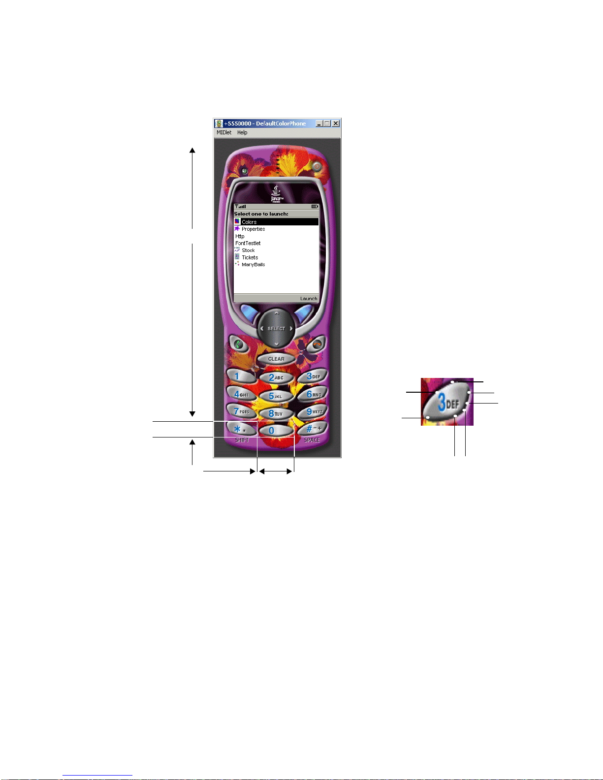
The button coordinates are shown in FIGURE 2 on page 11.
10 Wireless Toolkit Basic Customization Guide • December 2003
Page 25

Y
height
Y
FIGURE 2 Specifying a Button Location
2. Enter the following measured values for the button properties in
NewPhone.properties:
button.0 = 66, 417, 41, 22
button.1 = 21, 319, 41, 22
button.2 = 66, 320, 41, 22
button.3 = 110, 320, 41, 22
button.4 = 20, 352, 41, 22
button.5 = 65, 352, 41, 22
button.6 = 112, 352, 41, 22
X
width
Chapter 2 Creating Device Property Files 11
Page 26

button.7 = 21, 384, 41, 22
button.8 = 65, 384, 41, 22
button.9 = 111, 384, 41, 22
button.POUND = 110, 417, 41, 22
button.ASTERISK = 21, 417, 41, 22
button.SEND = 25, 295, 32, 17
button.END = 114, 295, 32, 17
button.LEFT = 37, 254, 26, 26
button.RIGHT = 114, 253, 23, 27
button.UP = 69, 232, 35, 22
button.SELECT = 65, 257, 43, 23
button.DOWN = 70, 284, 34, 21
button.UP.1 = 4, 87, 10, 18
button.DOWN.1 = 4, 189, 10, 20
button.SOFT1 = 29, 228, 33, 20
button.SOFT2 = 112, 227, 32, 20
button.POWER = 33, 52, 18, 10
Obtain and Enter Soft Button Label
Areas
1. By measuring the image file, obtain the soft button properties.
NewPhone has two soft buttons—similar to the DefaultColorPhone. Their label
areas are displayed in the area of the screen that is available to icons. This area is
not directly accessible to the application. FIGURE 3 on page 13 shows the soft
button labels Undo and Menu on the lower part of the device screen.
Note – See Chapter 3, “Examining Device Property Files” for information on how
to define devices with different numbers of soft buttons.
12 Wireless Toolkit Basic Customization Guide • December 2003
Page 27

Soft button labels
Soft Button Display Area
Full Dimension Name:
softbutton.<dimension>
y
height
x
FIGURE 3 Soft Button Label Areas on the Emulated Device Display
A soft button label display is defined by a line of the form:
softbutton.<number> = <x>,<y>,<
width
>,<
height
>,<
font
>,<
align
width
>
where the parameters are defined as follows:
■ The coordinates of the soft button label area:
■ x: The x-coordinate of the left edge of the label area, in pixels relative to the
left edge of the screen area
■ y: The y-coordinate of the top edge of the label area, in pixels relative to the
top edge of the screen area
■ width: The width of the label, in pixels
■ height: The height of the label, in pixels
■ font: The font of the soft button label
■ align: The alignment of the text of the soft button label within its area: "left",
"right" or "center"
2. Enter the following measured values for the soft button properties in
NewPhone.properties:
Chapter 2 Creating Device Property Files 13
Page 28

softbutton.0=1,112,40,16, softButton, left
softbutton.1=56,112,40,16, softButton, right
Obtain and Enter Icon Properties
An icon in the context of the Emulator is any graphic, constant or variable, that is
displayed on the device screen global region (the region that is outside of the
drawable area). This includes scrolling indicators, the battery level indicator and
any other images of a similar type. See Appendix A, “Default Emulator Device
Property Files” for a list of the icons provided with the J2ME Wireless Toolkit.
Icons are used by the J2ME Wireless Toolkit emulator to indicate the status of
several operations to the user:
■ The left, right, up and down icons indicate the possible scrolling operations.
■ The inmode icon indicates the current text input mode (Capital letters, small
letters or numbers).
■ The domain icon indicates whether the current MIDlet suite is assigned a
trusted domain.
An icon is defined by:
■ A name. One of a fixed set of icon names. DefaultColorPhone defines the
following set of icon names: left, right, up, down, inmode, internet,
reception, and battery.
■ A screen location. This is a coordinate pair giving the location of the top left
corner of the icon, in pixels relative to the top left corner of the screen area of the
device's image.
■ A default state. The icon is initially in this state.
■ A mapping of state names to image files. An icon can have any number of
named states, as long as it has a line in the property file for each state giving the
image associated with that state. If no image file is given for a particular state
then no image is displayed when the icon is in that state.
Note – Image files for icons with multiple states should be aligned with one
another, enabling a smooth visual transition on a change of state.
Defining the Icon Location and States
1. By measuring the image file, obtain the icons properties.
The screen location and initial state of the icon is defined by a line of the form:
14 Wireless Toolkit Basic Customization Guide • December 2003
Page 29

icon.<name> = <x_location>,<y_location>,<initial_state>
The icon states are defined by lines of the form:
icon.<name>.<state #1> = <state #1 image_filename>
..
icon.<name>.<state #n> = <state #n image_filename>
If an icon does not have an image for a particular state, only the name of the icon
need be given, and the image field can be left blank.
Image files can be in GIF, PNG, or JPEG format.
2. Enter the following measured values for the icons properties in
NewPhone.properties:
icon.up: 44, 112, off
icon.up.off:
icon.up.on: up.gif
icon.down: 44, 118, off
icon.down.off:
icon.down.on: down.gif
icon.left: 36, 114, off
icon.left.off:
icon.left.on: left.gif
icon.right: 52, 114, off
icon.right.off:
icon.right.on: right.gif
icon.internet: 64, 1, off
icon.internet.off:
icon.internet.on: internet.gif
icon.reception: 2, 1, on
icon.reception.on: reception.gif
icon.battery: 78, 2, on
icon.battery.on: batt.gif
icon.inmode: 28, 2, off
Chapter 2 Creating Device Property Files 15
Page 30

Enter Color Properties
Two properties are provided to control the color in the Emulator:
■ The isColor property determines whether the display is grayscale (false) or
color (true).
■ The colorCount property controls the number of colors available (when
isColor is true) or the number of shades of gray available (when isColor is
false).
● Enter the following measured values for the color properties in
NewPhone.properties.
colorCount = 0x100
isColor = false
Screen Background RGB Color
For a device with a grayscale screen, the background color of the screen can be set.
The color is defined as a hexadecimal integer according to the standard Java color
map. That is, the integer has the form RRGGBB, where RR, GG and BB are the red,
green and blue components of the color, respectively. For example, white would be
0xffffff and red would be 0xff0000.
The background color is defined with the property screenBGColor.
● Enter the following measured values for the screen background color properties
in NewPhone.properties.
screenBGColor = 0x64b890
Run the Emulator for the New Device
The new device, NewPhone, now appears in the list of available devices in
KToolbar. If you are already running these tools, you must restart the application to
see the updated list of devices.
16 Wireless Toolkit Basic Customization Guide • December 2003
Page 31

CHAPTER
3
Examining Device Property Files
This chapter explains in detail the structure and content of device property files for
an emulated device.
The following is the list of the main behavior items that can be specified in the
device property files:
■ device image
■ locations of buttons, and association of PC keys with device buttons
■ screen location and resolution
■ fonts
■ displayed icons
■ location, font and alignment of soft buttons
■ color support
■ MIDP abstract command implementation
By creating a new set of device property files, you can customize the behavior of
the items that are described above to fit with the behavior of the real device. The
folder wtklib\devices in the binary release of the J2ME Wireless Toolkit
contains the device property files.
The syntax of device property files is that of the standard Java 2 Standard Edition
property resources. For a description of the syntax, see the method detail for the
load method for the Properties class at the following website:
http://java.sun.com/j2se/1.4/docs/api/java/util/
Properties.html#load(java.io.InputStream)
For a description of the structure and content of device property files, see “Device
Property Files” on page 18.
Note – If you would like to have a new device property file posted on the J2ME
Wireless Toolkit web site, or distributed with the next version of the J2ME Wireless
Toolkit, send email to
wtk-comments@sun.com
.
17
Page 32

Device Property Files
The device property files consist of a set of files that define the device’s behavior
and appearance. Each set of device property files is located in a directory whose
name determines the name of the device.
{j2mewtk.dir} is used to refer to the directory in which the J2ME Wireless Toolkit is
installed. For example, if you installed the J2ME Wireless Toolkit in the default
directory C:\WTK21 then {j2mewtk.dir}\wtklib represents C:\WTK21\wtklib.
The device property directory must be located in {j2mewtk.dir}\wtklib\devices
so that it can be used by the J2ME Wireless Toolkit.
For example, TABLE 1 lists the device property file for a device named
DefaultGrayPhone and the shared property files used by all the devices
provided with the Wireless Toolkit. The DefaultGrayPhone device property file
is located at {j2mewtk.dir}\wtklib\devices\DefaultGrayPhone in the binary
installation. The shared device property files are located at
{j2mewtk.dir}\wtklib\devices\Share in the binary installation.
TABLE1 Example of Device Property Files and DefaultGrayPhone Property File
Property File Description
DefaultGrayPhone\DefaultGrayPhone.properties Main Device Property File
{j2mewtk.dir}\wtklib\devices\Share\ph1_neut.png Device image with buttons not pressed
{j2mewtk.dir}wtklib\devices\Share\ph1_press.png Device image with buttons pressed
{j2mewtk.dir}wtklib\devices\Share\ph1_highlight.png Device image with buttons highlighted
{j2mewtk.dir}wtklib\devices\Share\batt.gif Icon used in global region of device
{j2mewtk.dir}wtklib\devices\Share\down.gif Icon used in global region of device
{j2mewtk.dir}wtklibdevices\Share\internet.gif Icon used in global region of device
{j2mewtk.dir}wtklib\devices\Share\reception.gif Icon used in global region of device
{j2mewtk.dir}wtklib\devices\Share\up.gif Icon used in global region of device
See Appendix A, “Default Emulator Device Property Files” for a full example of
device property files.
18 Wireless Toolkit Basic Customization Guide • December 2003
Page 33

Main Device Property File
This section describes the device property file that the Default Emulator uses to
emulate a device.
The Main Device Property file is named
<
device_name>.properties and is located
in the directory <device_name> where device_name is the name of the device being
emulated. For example, the Main Device Property file for a device named
DefaultGrayPhone would be at
{j2mewtk.dir}\wtklib\devices\DefaultGrayPhone
\DefaultGrayPhone.properties. The Main Device Property file contains the
information needed to define the device's appearance and behavior, as well as
pointers to associated property files.
The Main Device Property file contains definitions for the following items. Each is
discussed in detail in the sections below.
■ Fonts
■ The Device Image
■ Screen Properties
■ Device Buttons
■ Displayed Icons
■ Soft Button Label Display
■ Color
■ Sound Alerts
■ Device Software Capabilities
Fonts
There are two types of fonts available for displaying text on the device screen:
■ Bitmap fonts configured for the Emulator
■ System fonts of the host PC
The device property file can specify the fonts used by the implementation of the
MIDP graphics API.
Fonts Used by the MIDP APIs
A font is specified by the MIDP APIs by the property:
font.<face>.<style>.<size> = <font definition>
where
■ face: “system”, “monospace”, or “proportional”
■ style: “plain”, “bold”, or “italic”
■ size: “small”, “medium”, or “large”
Chapter 3 Examining Device Property Files 19
Page 34

The font definition is according to the format for describing a system font (see
“System Fonts” on page 20) or a bitmap font (see “Bitmap Fonts” on page 20).
Example
font.system.italic.small: Helvetica-italic-9
The default font (see “Default Font”) is used for any MIDP font combination that is
not defined.
Default Font
A default font must be specified. This font is used in all cases where no other
definition was given.
The default font is specified as follows:
font.default = <font_properties_filename> | <system font definition>
Example
font.default = Arial-plain-12
System Fonts
A system font definition is in the standard Java format for specifying such a font.
For details, see
http://java.sun.com/j2se/1.4/docs/api/java/awt/Font.html
You can tell the Emulator to use the resident PC fonts to display text on the device
screen.
Use the font specification in the form:
font.<name> = <system font definition>
.
Example
font.softButton = Arial-plain-12
Bitmap Fonts
To tell the Emulator to use a bitmap font, you need to specify a font property file
that describes the font:
font.<font_name> = <font_property_filename>
20 Wireless Toolkit Basic Customization Guide • December 2003
Page 35
Example
font.softButton = bitmap_font.properties
font.system.bold.medium = bold_font.properties
A font property file contains definitions for the following properties:
font_image = <image_filename>
font_height = <pixel_height_font>
font_ascent = <pixel_ascent_font>
font_descent = <pixel_descent_font>
font_leading = <pixel_space_between_lines_of_text>
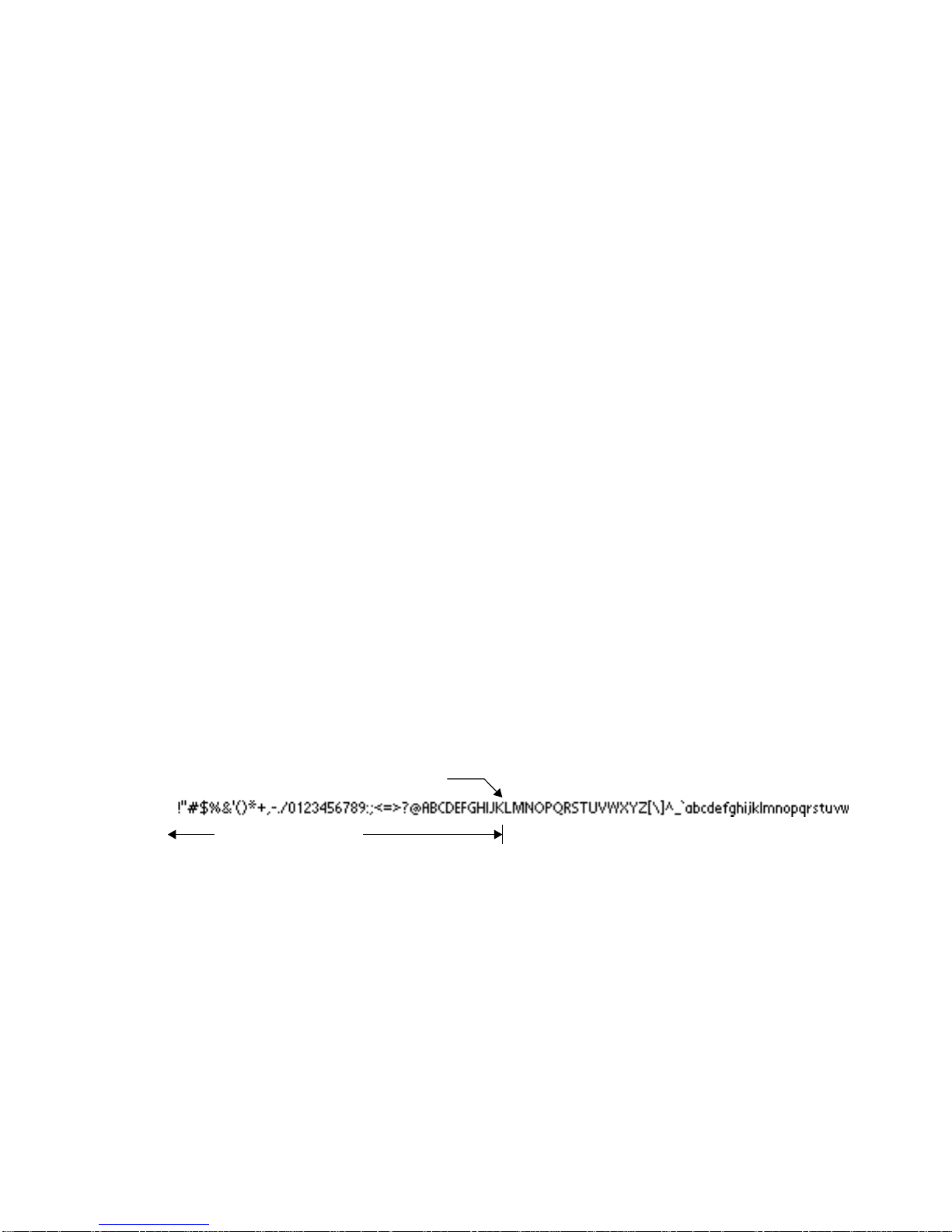
The first property, font_image, refers to an image file, in PNG, GIF or JPEG
format, that contains the font bitmap. The form of the bitmap should be a row of
characters, as shown in FIGURE 4.
The other properties listed above define other characteristics of the font:
■ height—the height of a character
■ ascent—the part of the character that is above the base line
■ descent—the part of a character that is below the base line
■ leading—the spacing between lines
For a complete description of height, ascent, descent and leading as they relate to
fonts, see
http://java.sun.com/j2se/1.4/docs/api/java/awt/FontMetrics.html
The bitmap font property file contains a list of properties of the form:
ascii_x-<n> = <horizontal pixel location in the image>
where <n> is a number between 0 and 256, and the given pixel location refers to
the start of that character's definition in the font bitmap. The characters must be
adjacent in the image, so that one character ends where another begins. The
following image shows the interpretation of the horizontal pixel locations:
ASCII character
Distance to character
FIGURE 4 Specifying Emulator Fonts
Example
ascii_x-0 = 0
ascii_x-1 = 0
..
ascii_x-32 = 0
ascii_x-33 = 8
Chapter 3 Examining Device Property Files 21
Page 36

..
ascii_x-254 = 1149
ascii_x-255 = 1154
ascii_x-256 = 1160
Note – This type of font supports only eight bit ASCII values (256 characters) and
not 16 bit unicode characters.
Font Underlining
The MIDP specification allows underlined fonts. By default, the emulator supports
font underlining. You can disable this feature for all fonts by setting the property:
font.all.underline.enabled = false
It is also possible to disable underlining for a specific font by setting the property:
font.<face>.<style>.<size>.underline.enabled = false
Where
on page 19.
It is possible to specify the thickness of the line used for underlining by a line of
the form:
font.<face>.<style>.<size>.underline.width = <width in pixels>
The default width of the line is one pixel for plain and italic font styles and two
pixels for the bold font style.
It is also possible to specify the distance of the line used for underlining from the
font baseline by a line of the form:
font.<face>.<style>.<size>.underline.offset = <offset from baseline in
The default offset is one pixel for all fonts.
face, style
pixels>
and
size
are as described in “Fonts Used by the MIDP APIs”
The Device Image
To specify the device image, you need to specify three separate device graphic
images. These image files should differ only in their representation of active
buttons (those buttons that are to be used in the emulation of the device in the
J2ME Wireless Toolkit).
The image files are:
■ A base image with all active buttons in a neutral state (not pressed or
highlighted)
22 Wireless Toolkit Basic Customization Guide • December 2003
Page 37

■ An image with all the active buttons pressed—to show a button being pressed
when the user selects it
■ An image with all the active buttons highlighted—to provide a visual indication
that the pointer is sufficiently positioned over a button that a mouse click will
activate the button.
Image files can be in GIF, PNG, or JPEG format.
Image without Buttons Pressed
To specify a device image without the buttons pressed, enter a line of the form:
default_image = <image_filename>
For example,
default_image = phone_base.png
Image with Buttons Pressed
To specify a device image with the buttons pressed, enter a line of the form:
pressed_buttons_image = <image_filename>
For example,
pressed_buttons_image = phone_pressed.png
Image with Buttons Highlighted and Backlight On
To specify a device image with the buttons highlighted and backlighting on, enter
a line of the form:
highlighted_image = <image_filename>
For example,
highlighted_image = phone_highlight.png
Scaling
To scale the device image, use an entry of the following form:
scale = <magnification_factor>
For example, the following entry expands the device image to twice its original
width and height:
scale = 2
Chapter 3 Examining Device Property Files 23
Page 38

Screen Properties
In this section you specify the properties of the image of the device screen. You
need to specify the following screen properties:
■ Screen Location
■ Total Screen Size
■ Display Area (optional)
■ Screen Pixel Ratio (optional)
■ Screen Background Color (optional)
■ Touch Screen (optional)
24 Wireless Toolkit Basic Customization Guide • December 2003
Page 39

Screen Location
Full Dimension Name:
screen.<dimension>
x
width
Display Area
Full Dimension Name:
y
screenPaintableRegion.<dimension>
height
x
y
height
width
full
screen
height
FIGURE 5 Specifying Screen Properties
Screen Location
Referring to the left image in FIGURE 5, you specify the location of the top left
corner of the screen relative to the top left corner of the device image by two lines
of the form:
Chapter 3 Examining Device Property Files 25
Page 40

screen.x = <horizontal distance in pixels>
screen.y = <vertical distance in pixels>
For example:
screen.x = 38
screen.y = 82
Total Screen Size
Referring to the left image in FIGURE 5 on page 25, you specify the total screen size
by two lines of the form:
screen.width = <horizontal distance in pixels>
screen.height = <vertical distance in pixels>
For example:
screen.width = 96
screen.height = 128
Display Area
Referring to the right image in FIGURE 5, the display area (or Paintable Region) is
that part of the screen that is available to applications. The remainder of the screen
is for icons and soft button labels.
The coordinates of the display area are relative to the screen location.
You can specify the display area used by the application to be a subregion of the
screen by four lines of the form:
screenPaintableRegion.x = <horizontal distance to display area>
screenPaintableRegion.y = <vertical distance to display area>
screenPaintableRegion.width = <width of display area>
screenPaintableRegion.height = <height of display area>
For example:
screenPaintableRegion.x = 4
screenPaintableRegion.y = 8
screenPaintableRegion.width = 88
screenPaintableRegion.height = 100
Note – If you do not specify the paintable region, the entire screen is used by an
application.
Display Area in Full Screen Mode
The MIDP 2.0 specification allows applications to use the full screen area.
26 Wireless Toolkit Basic Customization Guide • December 2003
Page 41

Referring to the right image in FIGURE 5, the full screen display area is defined as
the upper left coordinate of the display area, (screenPaintableRegion.x,
screenPaintableRegion.y), and the bottom right coordinate of the screen area
(screen.x+screen.width, screen.y+screen.height).
Customization of the display area will be available in future versions of the
Wireless Toolkit.
Screen Pixel Ratio
The following commands enable you to compensate for the difference in aspect
ratio between the actual device screen and the device image on the PC screen.
The pixel size ratio property defines the number of pixels in the device’s PC image
that correspond to a single pixel on the real device in both the horizontal and
vertical direction.
Note – MIDP requires that pixels be square. Therefore, you should only use pixel
ratios that preserve the square, for example, x:y = 2:2 or 3:3 (that is, magnifying
the image), and you should not use pixel ratios that distort the square, for example,
x:y = 1:2 or 2:1.
The ratios are defined as follows:
screenPixelRatio.x = horizontal_image_pixels/
horizontal_device_pixels
screenPixelRatio.y = vertical_image_pixels/vertical_device_pixels
For most devices, use the following values:
screenPixelRatio.x = 1
screenPixelRatio.y = 1
The values of screenPixelRatio.x and screenPixelRatio.y must be whole
numbers.
Screen Background Color
For a device with a grayscale screen, the background color of the screen can be set.
The color is defined as a hexadecimal integer according to the standard Java color
map. That is, the integer has the form RRGGBB, where RR, GG, and BB are the red,
green and blue components of the color, respectively. For example, white would be
0xffffff and red would be 0xff0000.
The background color is defined with the property screenBGColor.
For example:
screenBGColor = 0x64b890
Chapter 3 Examining Device Property Files 27
Page 42

Screen Border Color
You have the option of setting the color of the icon area, the softbutton area (nonpaintable areas), and the device menu. Screen background color is used if this
value is not defined. The color is defined as a hexadecimal integer according to the
standard Java color map. That is, the integer has the form RRGGBB, where RR, GG,
and BB are the red, green and blue components of the color, respectively. For
example, white would be 0xffffff and red would be 0xff0000. The screen
border color is defined with the property screenBorderColor.
For example:
screenBorderColor = 0xb6b6aa
Touch Screen
You can define whether or not your device should respond to mouse activity on its
screen. This is done by defining a property touch_screen to be either true or
false.
For example, setting
touch_screen = true
causes the device to respond to mouse activity on its screen.
The default value is:
touch_screen = false
Note – You only see the effect of the touch_screen property in MIDlets that are
specifically written for touch screens, such as the PushPuzzle demonstration
game included with the J2ME Wireless Toolkit. The user interface widgets in the
Default Emulator do not respond to touch screen events (for example, you cannot
select an item from a list by clicking on it with the mouse.)
Screen Buffering
By default, output from a MIDlet to the screen is buffered, so the screen is not
updated every time the application draws a line or writes some text. Instead, when
the application is ready, it signals MIDP that its drawing operations are complete,
and only then is the screen updated.
To see screen updates happen immediately, use the following entry:
screenDoubleBuffer = false
Use this entry if you want your applications to perform fewer drawing operations,
or if you are emulating a device that does not buffer screen output.
28 Wireless Toolkit Basic Customization Guide • December 2003
Page 43

Device Buttons
This section describes how to define a button on an emulated device and also
describes the assignments associated with the buttons including:
■ Assigning a keyboard key press to a button press
■ Assigning a game key to a button press
■ Specifying the character generated by a button press
■ Assigning an abstract command to a button press
Keyboard Handler
The set of names available for device buttons depends on the keyboard handler
being used.
There are two built-in keyboard handlers in the Toolkit:
■ ITU-T telephone keypad handler (the class DefaultKeyboardHandler)
■ A QWERTY keypad handler (the class QwertyKeyboardHandler)
You specify the keyboard handler by the keyboard.handler property, which
gives the name of the class to be used.
For example:
keyboard.handler = com.sun.kvem.midp.DefaultKeyboardHandler
Defining a Device Button
A button on the emulated device is defined in the main device property file by
name and screen location in one of the following forms:
button.<button_name> = x, y, width, height
button.<button_name> = x1, y1, x2, y2, x3, y3,...
For the first form (rectangular), the parameters are as follows:
■ button_name: The set of button names available is determined by the keyboard
handler in use, as shown in TABLE 2.
TABLE2 Button Names Available
Keyboard Handler Button Names
com.sun.kvem.midp.DefaultKeyboardHandler 0, 1, 2, 3, 4, 5, 6, 7, 8, 9, POUND,
ASTERISK, POWER, SEND, END,
LEFT, RIGHT, UP, DOWN,
SELECT, SOFT1, SOFT2, SOFT3,
SOFT4, CLEAR, USER1 through
USER10
Chapter 3 Examining Device Property Files 29
Page 44

■ x: The x-coordinate of the left edge of the button image, in pixels relative to the
left edge of the device image
■ y: The y-coordinate of the top edge of the button image, in pixels relative to the
top edge of the device image
■ width: The width of the button image, in pixels
■ height: The height of the button image, in pixels.
For example,
button.LEFT = 13, 197, 20, 20
For the second form (polygonal), the definitions for button_name, x, and y are the
same as for the rectangular form. The polygonal form can consist of multiple points
defined by x and y coordinates. A minimum of three sets of x and y coordinates are
required to use this form.
For example, if the LEFT button were polygonal, it could have the following
values:
button.LEFT = 166, 420, 143, 432, 143, 406
The button location and dimensions are used for two purposes:
■ To define the active region in which a mouse click is interpreted as a button
press.
■ To define the region of the device image that is used to show graphic effects on
device buttons.
The region for each button should be defined to be large enough to cover the
button's area on all three device images. However, be careful not to allow the
buttons' regions to overlap each other.
The button coordinates are shown in FIGURE 6.
30 Wireless Toolkit Basic Customization Guide • December 2003
Page 45
Y
height
x7,y7
x6,y6
x1,y1
x2,y2
x3,y3
x4,y4x5,y5
X
Rectangular Button Form Polygon Button Form
FIGURE 6 Specifying a Button Location
width
Assigning a PC Keyboard Key to a Button
You can assign a key on the PC keyboard to a device button in order to simulate a
button press by pressing the key (instead of clicking on the button with the mouse).
You use a line of the form:
key.<button_name> = <virtual key code>
Chapter 3 Examining Device Property Files 31
Page 46

Note – Virtual key codes are defined by the Abstract Window Toolkit in Java 2
Standard Edition. The definitions are found in the class
java.awt.event.KeyEvent at
http://java.sun.com/j2se/1.4/docs/api/java/awt/event/
KeyEvent.html
For example,
key.LEFT = VK_LEFT
More than one PC key may be assigned to a single button, using the form:
key.<button_name> = <list of virtual key codes>
where the virtual key codes are separated by spaces.
For example,
key.0 = VK_0 VK_NUMPAD0
Assigning a Game Action to a Button
The QwertyKeyboardHandler also allows the MIDP game actions to be mapped to
device buttons. You use a line of the form:
game.<function> = <button_name>
where function can be one of LEFT, RIGHT, UP, DOWN and SELECT and
button_name is the name of a button as shown in TABLE 2 on page 29.
The default settings are:
game.UP = UP
game.DOWN = DOWN
game.LEFT = LEFT
game.RIGHT = RIGHT
game.SELECT = SELECT
Specifying the Characters Generated by a Button Press
When using the QwertyKeyboardHandler, you can also specify the character
generated by a button press either alone or in combination with the Shift or Alt
buttons.
You use a line of the form:
keyboard.handler.qwerty.<button_name> = '<base character>' '<shift
character>' '<alternate character>'
where base character is the character the button normally generates, shift
character is the character used when the button is pressed at the same time as
Shift, and alternate character is the character generated when the button is
pressed at the same time as Alt.
32 Wireless Toolkit Basic Customization Guide • December 2003
Page 47

There are two ways you can do a button press at the same time as pressing Shift or
Alt:
■ Map the buttons to the keyboard, as in the previous section, and press the key
associated with the button at the same time as the Shift or Alt keys
■ Press the button Shift-Lock or Alt-Lock and then do the button press. Press
Shift-Lock or Alt-Lock again to revert to the initial state.
For example:
keyboard.handler.qwerty.A = 'a' 'A' '?'
Assigning Abstract Commands to Buttons
Abstract commands are provided in the MIDP specification in order to allow an
application to issue a screen command without having to take into account how the
user selects that command on a specific device—making the application more
portable. The idea is to separate the semantics of the command from its execution
on the device. The semantics are defined in the application and the execution is
defined in the implementation of MIDP on the specific device.
The semantics of an abstract command include:
■ Label—the command name for display purposes
■ Type—the category of the command, for example BACK or HELP. The command
type is used to help determine how a command is mapped onto a device
■ Priority—a priority number. The command priority is used to help determine
how a command is mapped onto a device.
In the MIDP Reference Implementation, which underlies the J2ME Wireless Toolkit,
there is an implicit order of precedence among the command types. This command
precedence also impacts on the assignment of a command to a preferred button. If
two commands of different types are vying for the same button, the command
whose type has higher precedence prevails.
TABLE 3 shows the abstract command types in order of precedence in the J2ME
Wireless Toolkit and the MIDP Reference Implementation:
TABLE3 Abstract Command Types in Order of Precedence
Command Type Description
BACK Returns the user to the logically previous screen
EXIT Exits from the application
CANCEL Standard negative answer to a dialog implemented by the
current screen
STOP Stop some currently running process or operation
Chapter 3 Examining Device Property Files 33
Page 48

TABLE3 Abstract Command Types in Order of Precedence
Command Type Description
OK Standard positive answer to a dialog implemented by current
screen
SCREEN Specifies an application-defined command that pertains to the
current screen, for example, "Load" and "Save"
ITEM The command is specific to a particular item on the screen
HELP Request for on-line help
The MIDP implementation in the Wireless Toolkit allocates a command issued by
the application to a device button based on the following considerations:
1. The first consideration is the natural correspondence between the command’s
type and a input signal such as a button press. For example, if the BACK
command type is usually associated with the left soft button, then the
implementation first tries to assign it there. If there is no such preferred button
for a command type, this consideration is not relevant.
2. The secondary consideration is assignment of the remaining commands that
could not be assigned to their preferred buttons. The command precedence and
the command priority are used to assign these commands to alternate buttons or
to a command menu.
The J2ME Wireless Toolkit allows a variety of abstract command mapping policies
to be implemented. An emulated device can use a combination of soft buttons and
dedicated command buttons to implement abstract commands, or it can have none
of these and just present all abstract commands to the user in an on-screen menu.
The J2ME Wireless Toolkit includes examples of different configurations (see the
Wireless Toolkit User’s Guide).
Note – The mapping policy for abstract commands can vary across actual devices.
For example, command type precedence may differ.
Emulating Abstract Command Button Assignments
The Emulator provides the device property file definitions
command.keys.<command_type> and command.menu.<action> to emulate the
way a MIDP implementation on the corresponding real device assigns abstract
commands to buttons and menus.
You specify the button assignments following the considerations specified at the
end of the previous section:
1. Use the definitions command.menu.activate and command.menu.<action> to
assign the menu operations to buttons. See “The Abstract Command Menu” on
page 37.
34 Wireless Toolkit Basic Customization Guide • December 2003
Page 49

2. Use the definition command.keys.<command_type> to assign command types to
preferred buttons according to their natural correspondence. See “Assigning an
Abstract Command Type to a Button” on page 35
3. Use the secondary button assignments to specify alternate buttons for assigning
commands of lower priority. See “Secondary Button Assignments” on page 36.
Note – To achieve an accurate emulation, these assignments need to be made in
accordance with the way the MIDP implementation for the specific device would
make them.
Precedence of Assigning Commands to a Button
In the J2ME Wireless Toolkit, commands are assigned to buttons according to the
following order of preference:
1. Menu operations
2. Abstract command precedence
3. Abstract command priority
First, the menu operations are assigned to the buttons that are defined for them.
Then the abstract commands are assigned. Abstract command precedence is taken
into account before abstract command priority. Thus, if a command of type BACK
with priority 2 and a command of type EXIT with priority 1 are competing for a
button, the BACK command will get the assignment due to its higher precedence.
Command priority is taken into account only when the two commands have the
same type.
Assigning an Abstract Command Type to a Button
You assign an abstract command type to a button using a property definition of the
form:
command.keys.<type> = <button_name>
where <type> is one of the abstract command types shown in TABLE 3 on page 33.
The button name is one of the names listed in TABLE 2 on page 29.
Example
If you want to assign command types to the two soft buttons as follows:
■ Left soft button: command types BACK, EXIT, CANCEL and STOP
■ Right soft button: command types OK, SCREEN, ITEM, HELP
you would enter the following definitions in the main device property file:
Chapter 3 Examining Device Property Files 35
Page 50

command.keys.BACK = SOFT1
command.keys.EXIT = SOFT1
command.keys.CANCEL = SOFT1
command.keys.STOP = SOFT1
command.keys.OK = SOFT2
command.keys.SCREEN = SOFT2
command.keys.ITEM = SOFT2
command.keys.HELP = SOFT2
In cases of conflict in the mapping of actual commands to keys, commands are
mapped first by command type and then by priority.
Secondary Button Assignments
Secondary buttons may be defined for a command type. If a command is unable to
be assigned to the preferred button for its type because another command with
higher precedence (due to either its type or its priority) has taken the button, the
command can be assigned to an alternative button.
This is done by specifying more than one button name in the property definition
where the names are separated by spaces:
command.keys.<type> = <button_name> <button_name> .. <button_name>
Example
The first definition below assigns commands of type BACK to the END key and
alternatively to the SOFT1 key. The second definition assigns commands of type
OK to the SEND key and alternatively to the SOFT2 key.
command.keys.BACK = END SOFT1
command.keys.OK = SEND SOFT2
Restricting the List of Command Types for a Soft Button
Only certain command types might be allowed for a specific soft button, which
means that other command types will not be assigned to that soft button in any
case, even if that soft button is left unassigned.
You restrict command types to a button by specifying a list of one or more
command types in the property definition:
command.exclusive.<button_name> = <type> <type> ... <type>
Example
The following definition allows only the command types BACK, EXIT, CANCEL,
and STOP to be mapped to the SOFT1 key.
command.exclusive.SOFT1 = BACK EXIT CANCEL STOP
36 Wireless Toolkit Basic Customization Guide • December 2003
Page 51

The Abstract Command Menu
When there are more abstract commands specified by an application than there are
buttons to which they can be mapped, the unmapped abstract commands are
placed in a command menu. The following operations are defined for the
command menu:
■ Display/hide menu
■ Select menu item
■ Scroll/Traverse up menu
■ Scroll/Traverse down menu
These menu operations are assigned to buttons as described below.
One button is used to alternately display and hide the menu. It is defined by the
property command.menu.activate using the format:
command.menu.activate = <button_name>
The buttons used to navigate the menu are defined using the following properties:
command.menu.select = <menu_select_key>
command.menu.up = <menu_up_key>
command.menu.down = <menu_down_key>
The default values for these properties are:
command.menu.select = SELECT
command.menu.up = UP
command.menu.down = DOWN
Example
This example sets the menu to be activated by the SOFT2 key and to be navigated
with the standard keys.
command.menu.activate = SOFT2
Customizing Menu Title and Soft Button
You can customize the title of the menu as well as the label of the soft button used
to display and hide the menu. Use the following properties:
menu.text.title = <menu title>
menu.title.activate = <soft button label>
The default values for these properties are:
menu.text.title = Menu
menu.title.activate = Menu
Note – Real devices can have alternate human interfaces that employ means other
than menus to handle commands that cannot be mapped to keys.
Chapter 3 Examining Device Property Files 37
Page 52

Displayed Icons
An icon in the context of the Emulator is any graphic, constant or variable, that is
displayed on the device screen global region (the region that is outside of the
drawable area). This includes scrolling indicators, the battery level indicator and
any other images of a similar type.
An icon is defined by:
■ A name. This name must be known to the Java code that uses the icon. For
example, the code to implement scrolling indicators looks for icons named “up”
and “down”.
■ A screen location. This is a coordinate pair giving the location of the top left
corner of the icon, in pixels relative to the top left corner of the screen area of the
device's image.
■ A default state. The icon is initially in this state.
■ A mapping of state names to image files. An icon can have any number of
named states, as long as it has a line in the property file for each state giving the
image associated with that state. If no image file is given for a particular state
then no image is displayed when the icon is in that state.
Defining the Icon Location and States
The screen location and initial state of the icon is defined by a line of the form:
icon.<name> = <x location>,<y location>,<initial state>
The icon states are defined by lines of the form:
icon.<name>.<state #1> = <state #1 image_filename>
..
icon.<name>.<state #n> = <state #n image_filename>
If an icon does not have an image for a particular state, only the name of the icon
need be given, and the image field can be left blank.
Image files can be in GIF, PNG, or JPEG format.
For example:
icon.up: 44, 110, off
icon.up.off:
icon.up.on: up.gif
icon.down: 44, 118, off
icon.down.off:
icon.down.on: down.gif
icon.internet: 64, 0, off
icon.internet.off:
icon.internet.on: internet.gif
38 Wireless Toolkit Basic Customization Guide • December 2003
Page 53

icon.reception: 0, 0, on
icon.reception.on: reception.gif
icon.battery: 80, 0, full
icon.battery.full: batt_3.gif
icon.battery.half: batt_2.gif
icon.battery.low: batt_1.gif
icon.battery.none: batt_0.gif
Soft Button Label Display
On devices with soft buttons, soft button labels are displayed in the area of the
screen that is available to icons. This area is not directly accessible to the
application. FIGURE 7 shows the soft button labels Undo and Menu on the lower
part of the device screen.
Soft button labels
FIGURE 7 Soft Button Labels on the Emulated Device Display
A soft button label display is defined by a line of the form:
Chapter 3 Examining Device Property Files 39
Page 54

softbutton.<number> = <x>,<y>,<width>,<height>,<font>,<align>
where the parameters are defined as follows:
■ The coordinates of the soft button label:
■ x: The x-coordinate of the left edge of the label area, in pixels relative to the
left edge of the screen area
■ y: The y-coordinate of the top edge of the label area, in pixels relative to the
top edge of the screen area
■ width: The width of the label, in pixels
■ height: The height of the label, in pixels
■ font: The font of the soft button label
■ align: The alignment of the text of the soft button label within its area: "left",
"right" or "center"
For example:
softbutton.0 = 0,110,36,18, softButton, left
softbutton.1 = 60,110,36,18, softButton, right
Color
Three properties are provided to control the color in the Emulator:
■ The isColor property determines whether the display is grayscale (false) or
color (true).
■ The colorCount property controls the number of colors available (when
isColor is true) or the number of shades of gray available (when isColor is
false).
■ The gamma property determines the level of gamma correction to be used when
displaying the device's screen. The default value of this property is 1.0.
For example:
isColor = false
colorCount = 256
gamma = 2.0
Sound Alerts
Sounds that are played when alert with sound is displayed can be specified.
Default sound can be specified by setting the option:
alert.default.sound = <sound_file>
This sound file will be used for all alerts where an alert-specific sound is not
defined. Sound for each alert can be defined by:
40 Wireless Toolkit Basic Customization Guide • December 2003
Page 55

alert.<alert_type>.sound = <sound_file>
where the possible values of <alert_type> are as defined by MIDP specification as
follows:
TABLE4 Alert Type Values
Alert Type Description
info Typically provides non-threatening information to the user.
error Alerts the user to an erroneous operation.
warning Warns the user of a potentially dangerous operation.
confirmation Confirms user actions
alarm Alerts the user to an event for which the user has previously
requested to be notified
If no sound file is defined (no alert-specific sound and no default sound) for a
particular alert, the emulator does not play the sound and the corresponding MIDP
API method AlertType.playSound() method returns the value false.
The Emulator supports all sound file formats currently supported by JDK1.4:
■ Audio file formats: AIFF, AU and WAV
■ Music file formats: MIDI Type 0, MIDI Type 1, and Rich Music Format (RMF)
■ Sound formats: 8-bit and 16-bit audio data, in mono and stereo, with sample
rates from 8 kHz to 48 kHz
■ Linear, A-law, and mu-law encoded data in any of the supported audio file
formats
Device Software Capabilities
The Default Emulator in the J2ME Wireless Toolkit enables you to define device
emulations with additional capabilities that are not required by the MIDP
specification. Specifically,
■ You can specify a default locale.
■ You can specify what character encodings are available in the device emulation.
■ You can disallow use of transparent images in the device emulation.
This section describes how to use these options.
Chapter 3 Examining Device Property Files 41
Page 56

Locales
A locale is a geographic or political region or community that shares the same
language, customs, or cultural convention. In software, a locale is a collection of
files, data, and code, which contains the information necessary to adapt software to
a specific geographical location.
Some operations are locale-sensitive and require a specified locale to tailor
information for users, such as:
■ Messages displayed to the user
■ Cultural information such as, dates and currency formats
In the Default Emulator, the default locale is determined by the platform’s locale.
To define a default locale, use the following definition:
microedition.locale: <default_locale>
A locale name is comprised of two parts separated by an dash (-), for example,
en-US is the locale designation for english/United States while en-AU is the
designation for english/Australia.
The first part is a valid ISO Language Code. These codes are the lower-case twoletter codes as defined by ISO-639. You can find a full list of these codes at a
number of sites, such as:
http://www.ics.uci.edu/pub/ietf/http/related/iso639.txt
The second part is a valid ISO Country Code. These codes are the upper-case twoletter codes as defined by ISO-3166. You can find a full list of these codes at a
number of sites, such as:
http://www.chemie.fu-berlin.de/diverse/doc/ISO_3166.html
Character Encodings
The input/output APIs in CLDC use named character encodings to convert 8-bit
characters into 16-bit Unicode characters, and vice-versa. A MIDP implementation
might make only a small set of encodings available for MIDlets to use.
In the Default Emulator, the default encoding is default encoder of the platform
you are running on. Your emulator might use other encodings, such as UTF-8 and
UTF-16, providing they are available in the J2SE platform.
To define the default character encoding used by the emulator, use the following
definition:
microedition.encoding: <default_encoding>
To define the set of all available encodings, use the following definition:
microedition.encoding.supported: <list of encodings>
For example:
42 Wireless Toolkit Basic Customization Guide • December 2003
Page 57

microedition.encoding: UTF-8
microedition.encoding.supported: UTF-8, UTF-16, ISO-8859-1,
ISO-8859-2, Shift_JIS
To support all encodings supported by the J2ME platform, leave the
microedition.encoding.supported definition blank, as in:
microedition.encoding.supported:
Note – The encoding ISO-8859-1 is always available to applications running on
emulated devices, whether or not it is listed in the
microedition.encoding.supported entry.
Transparent Images
The Default Emulator supports the alpha channel in the image data by default. To
disable the alpha channel in the image data, change the value of the
enableAlphaChannel property from true to false:
enableAlphaChannel: false
Chapter 3 Examining Device Property Files 43
Page 58

44 Wireless Toolkit Basic Customization Guide • December 2003
Page 59

APPENDIX
A
Default Emulator Device
Property Files
This appendix presents a list of the device property files provided with the Default
Emulator and information on the Default Emulator properties.
Property Files
The following property files are used.
TABLE5 Example of Device Property Files
Property File Description
DefaultGrayPhone\DefaultGrayPhone.properties Main Device Property File
{j2mewtk.dir}\wtklib\devices\Share\ph1_neut.png Device image with buttons not pressed
{j2mewtk.dir}\wtklib\devices\Share\ph1_press.png Device image with buttons pressed
{j2mewtk.dir}\wtklib\devices\Share\ph1_highlight.png Device image with buttons highlighted
{j2mewtk.dir}\wtklib\devices\Share\123.gif Icon used on device screen
{j2mewtk.dir}\wtklib\devices\Share\ABC.gif Icon used on device screen
{j2mewtk.dir}\wtklib\devices\Share\abc_lower.gif Icon used on device screen
{j2mewtk.dir}\wtklib\devices\Share\batt.gif Icon used on device screen
{j2mewtk.dir}\wtklib\devices\Share\down.gif Icon used on device screen
{j2mewtk.dir}\wtklib\devices\Share\hira.gif Icon used on device screen
{j2mewtk.dir}\wtklib\devices\Share\indicator.png Device image of backlight indicator LED
{j2mewtk.dir}\wtklib\devices\Share\internet.gif Icon used on device screen
{j2mewtk.dir}\wtklib\devices\Share\kana.gif Icon used on device screen
{j2mewtk.dir}\wtklib\devices\Share\left.gif Icon used on device screen
45
Page 60

TABLE5 Example of Device Property Files
Property File Description
{j2mewtk.dir}\wtklib\devices\Share\reception.gif Icon used on device screen
{j2mewtk.dir}\wtklib\devices\Share\right.gif Icon used on device screen
{j2mewtk.dir}\wtklib\devices\Share\secure.gif Icon used on device screen
{j2mewtk.dir}\wtklib\devices\Share\sym.gif Icon used on device screen
{j2mewtk.dir}\wtklib\devices\Share\trusted.png Icon used on device screen
{j2mewtk.dir}\wtklib\devices\Share\unsecure.gif Icon used on device screen
{j2mewtk.dir}\wtklib\devices\Share\up.gif Icon used on device screen
DefaultGrayPhone.properties
default_image=..\Share\ph1_neut.png
pressed_buttons_image=..\Share\ph1_press.png
highlighted_image=..\Share\ph1_highlight.png
## screen properties ##
# Screen location, relative to the top-left corner of the
# telephone's image
###############
screen.x=30
screen.y=131
# Screen size in pixels
###############
screen.width=180
screen.height=208
# The region of the screen available to graphics commands
# This section is optional. It defines the drawable region
# of the screen to be a subregion of the whole screen area.
###############
screenPaintableRegion.x=0
screenPaintableRegion.y=11
screenPaintableRegion.width=180
screenPaintableRegion.height=178
# pixel size ratio (shape of each pixel).
# example: 1x1=square pixel, 1x2=rectangular pixel
###############
46 Wireless Toolkit Basic Customization Guide • December 2003
Page 61

screenPixelRatio.x = 1
screenPixelRatio.y = 1
# Touchscreen support
###############
touch_screen=false
# Screen Background RGB Color
# examples: 0xffffff = white, 0x000000 = black
###############
screenBGColor=0x8f9f8f
# Screen border RGB color is a color of softbuttons and icons
# area. If not defined, screen background color is used
# example: screenBorderColor = 0xf0f0f
###############
screenBorderColor=0xb6b6aa
# Transparency support
# SRC_OVER alpha composition rule
# supported by deafult
###############
enableAlphaChannel=true
netindicator.image: ../Share/indicator.png
netindicator.bounds: 17, 82, 19, 19
button.0 = 98, 578, 47, 35
button.1 = 33, 459, 45, 35
button.2 = 98, 464, 47, 30
button.3 = 166, 459, 45, 35
button.4 = 36, 498, 45, 35
button.5 = 98, 503, 47, 30
button.6 = 162, 498, 45, 35
button.7 = 43, 537, 47, 35
button.8 = 98, 542, 47, 30
button.9 = 154, 537, 47, 35
button.POUND = 151, 578, 45, 29
button.ASTERISK = 48, 578, 45, 30
button.SEND = 24, 384, 39, 39
button.END = 181, 384, 39, 39
button.LEFT = 71, 352, 26, 63
button.RIGHT = 147, 352, 26, 63
button.UP = 97, 348, 50, 22
Appendix A Default Emulator Device Property Files 47
Page 62

button.SELECT = 97, 370, 50, 28
button.DOWN = 97, 398, 50, 22
button.CLEAR = 92, 426, 58, 31
button.SOFT1 = 31, 350, 39, 31
button.SOFT2 = 175, 350, 36, 31
button.POWER = 157, 53, 30, 30
command.keys.BACK = SOFT1
command.keys.EXIT = SOFT1
command.keys.CANCEL = SOFT1
command.keys.STOP = SOFT1
command.keys.OK = SOFT2
command.keys.SCREEN = SOFT2
command.keys.ITEM = SOFT2
command.keys.HELP = SOFT2
command.exclusive.SOFT1 = BACK, EXIT, CANCEL, STOP
command.menu.activate = SOFT2
keyboard.handler = com.sun.kvem.midp.DefaultKeyboardHandler
key.0 = VK_0 VK_NUMPAD0
key.1 = VK_1 VK_NUMPAD1
key.2 = VK_2 VK_NUMPAD2
key.3 = VK_3 VK_NUMPAD3
key.4 = VK_4 VK_NUMPAD4
key.5 = VK_5 VK_NUMPAD5
key.6 = VK_6 VK_NUMPAD6
key.7 = VK_7 VK_NUMPAD7
key.8 = VK_8 VK_NUMPAD8
key.9 = VK_9 VK_NUMPAD9
key.POUND = VK_SUBTRACT
key.ASTERISK = VK_MULTIPLY
key.POWER = VK_ESCAPE
key.UP = VK_UP
key.DOWN = VK_DOWN
key.LEFT = VK_LEFT
key.RIGHT = VK_RIGHT
key.SELECT = VK_ENTER
key.SOFT1 = VK_F1
key.SOFT2 = VK_F2
key.SEND = VK_HOME
key.END = VK_END
key.CLEAR = VK_BACK_SPACE
# Multiple font support:
# font.<face>.<style>.<size>=<font properties filename> |
# <system font definition>
# Where
48 Wireless Toolkit Basic Customization Guide • December 2003
Page 63

# <face> is one of
# system, monospace, proportional
#
# <style> is one of
# plain, bold, italic
#
# <size> is one of
# small, medium, large
#
# Default font is defined by
# font.default=<font properties filename> | <system font definition>
#
# Soft Button font defined by
# font.softButton=<font properties filename> | <system font
definition>
#
font.default=SansSerif-plain-10
font.softButton=SansSerif-plain-11
font.system.plain.small: SansSerif-plain-9
font.system.plain.medium: SansSerif-plain-11
font.system.plain.large: SansSerif-plain-14
font.system.bold.small: SansSerif-bold-9
font.system.bold.medium: SansSerif-bold-11
font.system.bold.large: SansSerif-bold-14
font.system.italic.small: SansSerif-italic-9
font.system.italic.medium: SansSerif-italic-11
font.system.italic.large: SansSerif-italic-14
font.system.bold.italic.small: SansSerif-bolditalic-9
font.system.bold.italic.medium: SansSerif-bolditalic-11
font.system.bold.italic.large: SansSerif-bolditalic-14
font.monospace.plain.small: Monospaced-plain-9
font.monospace.plain.medium: Monospaced-plain-11
font.monospace.plain.large: Monospaced-plain-14
font.monospace.bold.small: Monospaced-bold-9
font.monospace.bold.medium: Monospaced-bold-11
font.monospace.bold.large: Monospaced-bold-14
font.monospace.italic.small: Monospaced-italic-9
font.monospace.italic.medium: Monospaced-italic-11
Appendix A Default Emulator Device Property Files 49
Page 64

font.monospace.italic.large: Monospaced-italic-14
font.monospace.bold.italic.small: Monospaced-bolditalic-9
font.monospace.bold.italic.medium: Monospaced-bolditalic-11
font.monospace.bold.italic.large: Monospaced-bolditalic-14
font.proportional.plain.small: SansSerif-plain-9
font.proportional.plain.medium: SansSerif-plain-11
font.proportional.plain.large: SansSerif-plain-14
font.proportional.bold.small: SansSerif-bold-9
font.proportional.bold.medium: SansSerif-bold-11
font.proportional.bold.large: SansSerif-bold-14
font.proportional.italic.small: SansSerif-italic-9
font.proportional.italic.medium: SansSerif-italic-11
font.proportional.italic.large: SansSerif-italic-14
font.proportional.bold.italic.small: SansSerif-bolditalic-9
font.proportional.bold.italic.medium: SansSerif-bolditalic-11
font.proportional.bold.italic.large: SansSerif-bolditalic-14
# Font underlining :
#
# Font underlining is enabled by default. It is possible to disable
font underlining with
#
# font.all.underline.enabled=false
#
# or per font with
#
# font.<face>.<style>.<size>.underline.enabled=false
# Multistate icons support:
#
# icon.<name> = <x location>,<y location>,<initial state>
# icon.<name>.<state #1> = <state #1 image file name>
# ..
# icon.<name>.<state #n> = <state #n image file name>
icon.up: 86, 192, off
icon.up.off:
icon.up.on: ..\Share\up.gif
icon.down: 86, 198, off
icon.down.off:
50 Wireless Toolkit Basic Customization Guide • December 2003
Page 65

icon.down.on: ..\Share\down.gif
icon.left: 78, 194, off
icon.left.off:
icon.left.on: ..\Share\left.gif
icon.right: 94, 194, off
icon.right.off:
icon.right.on: ..\Share\right.gif
icon.internet: 64, 1, off
icon.internet.off:
icon.internet.on: ..\Share\internet.gif
icon.reception: 2, 1, on
icon.reception.on: ..\Share\reception.gif
icon.battery: 164, 2, on
icon.battery.on: ..\Share\batt.gif
icon.inmode: 83, 2, off
icon.inmode.off:
icon.inmode.ABC: ..\Share\ABC.gif
icon.inmode.abc: ..\Share\abc_lower.gif
icon.inmode.123: ..\Share\123.gif
icon.inmode.kana: ..\Share\kana.gif
icon.inmode.hira: ..\Share\hira.gif
icon.inmode.sym: ..\Share\sym.gif
icon.domain: 149, 0, off
icon.domain.off:
icon.domain.trusted: ..\Share\trusted.png
#
# Sound support:
# alert.<alert_type>.sound: <sound_file>
# Where possible <alert_type> are
#
# alarm
# info
# warning
# error
# confirmation
#
# Default sound type is used for all alerts where specific sound is
not defined:
# alert.default.sound: <sound_file>
alert.alarm.sound: ..\Share\mid_alarm.wav
alert.info.sound: ..\Share\mid_info.wav
alert.warning.sound: ..\Share\mid_warn.wav
Appendix A Default Emulator Device Property Files 51
Page 66

alert.error.sound: ..\Share\mid_err.wav
alert.confirmation.sound: ..\Share\mid_confirm.wav
# Softbuttons support:
# softbutton.<number>=<x location>,<y
location>,<width>,<height>,<font>
#
# Coordinates are relative to the origin of the screen area.
softbutton.0=1,192,78,16, softButton, left
softbutton.1=99,192,78,16, softButton, right
#
# Gamma value for gamma-correction
# Default value is 1, which means that no gamma-correction is
actually performed
#
gamma=2
# Color/Grayscale screen support:
colorCount=0x100
isColor=false
#
# These are the labels for the menu softbutton and the menu screen
# in the device. They are here so the phones can be localized
# individually rather than globally.
#
menu.text.title=Menu
menu.text.activate=Menu
52 Wireless Toolkit Basic Customization Guide • December 2003
Page 67
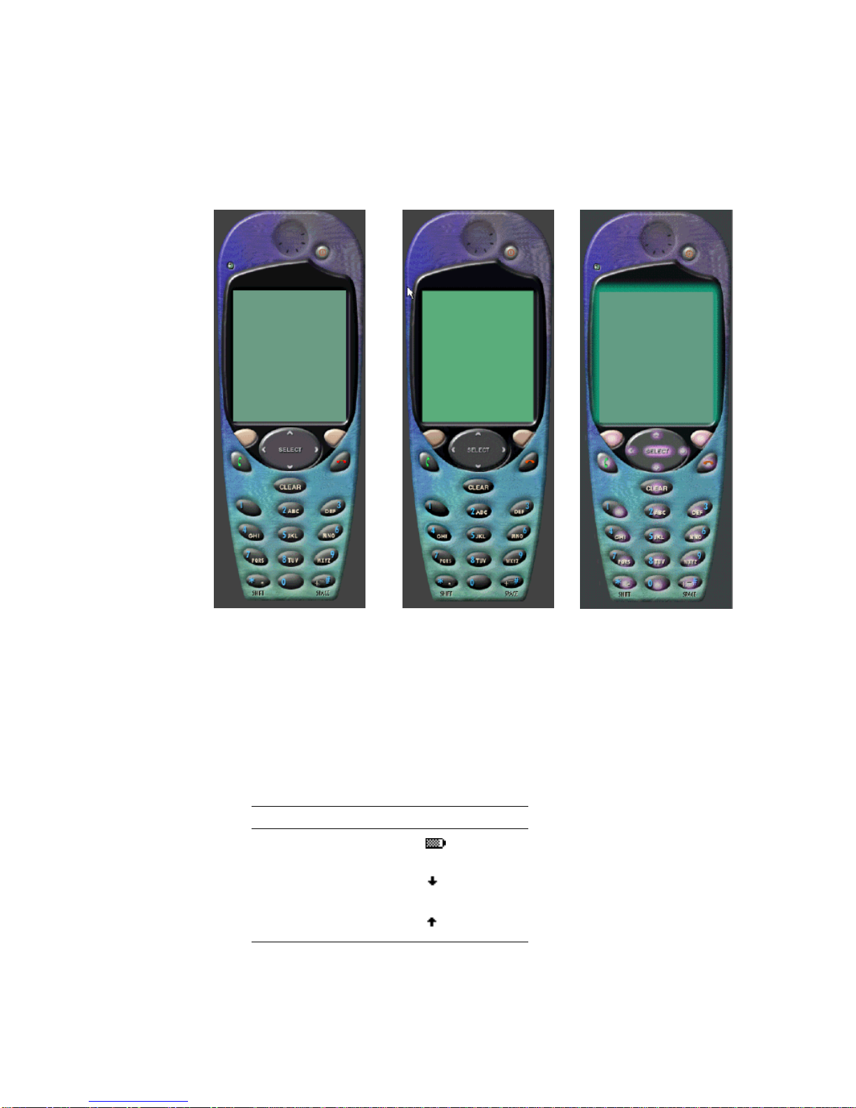
Device Image Files
ph1_neut.png ph1_press.png ph1_highlight.png
FIGURE 8 Images of Device Key Press States
Icon Image Files
The following table lists filenames and their associated images:
TABLE6 Icon Image Files
Filename Image
batt.gif
down.gif
up.gif
Appendix A Default Emulator Device Property Files 53
Page 68

TABLE6 Icon Image Files
Filename Image
internet.gif
reception.gif
right.gif
left.gif
sym.gif
kana.gif
hira.gif
ABC.gif
abc_lower.gif
123.gif
secure.gif
unsecure.gif
trusted.gif
54 Wireless Toolkit Basic Customization Guide • December 2003
Page 69

APPENDIX
B
Support for ByteCode Obfuscators
The Wireless Toolkit contains a support framework for bytecode obfuscators. It also
includes a plug-in for this framework for the ProGuard and Retroguard bytecode
obfuscators. You can use a bytecode obfuscator other than ProGuard or
RetroGuard, however, you must manually implement the plug-in for it. This
appendix describes the implementation procedure.
Adding a ByteCode Obfuscator
To plug in a bytecode obfuscator of your choice into the Wireless Toolkit’s
packaging process, you must follow these steps:
1. Write your own Java class that implements the
com.sun.kvem.environment.Obfuscator interface.
The class file for this interface is located in the {j2mewtk.dir}\wtklib\kenv.zip
file. The implementation class needs to implement the following two interface
methods:
■ createScriptFile(File jadFilename, File projectDir)
55
Page 70

■ run(File jarFileObfuscated, String wtkBinDir,
String wtkLibDir, String jarFilename, String projectDir,
String classPath, String emptyApi)
where
jarFileObfuscated is the file that holds the obfuscated JAR
wtkBinDir is the directory holding the Wireless Toolkit binary files
wtkLibDir is the directory holding the Wireless Toolkit JAR files
jarFilename is the full path to the JAR file to be obfuscated
projectDir is the full path to the main directory of your project
classPath is the full path to the set of files that make up the API classpath for
the project based on your API selections in the Project Settings dialog box, for
example, the paths for the cldcapi10.jar and midpapi20.jar files.
emptyApi is the full path to the version of the MIDP API containing stub
methods (that is, method signatures without method bodies) in the
{j2mewtk.dir}\wtklib directory
The first method creates a script file that is used by most obfuscators as a method
of input to determine which classes and methods are not to be obfuscated. The
second method is called when the Wireless Toolkit attempts to execute the
obfuscator.
2. You must add the following properties to the ktools.properties file located
in {j2mewtk.dir}\wtklib\Windows:
■ obfuscator.runner.class.name. The fully qualified name of the class
implementing the obfuscator interface. This property tells the Wireless Toolkit
the class name it needs to load to execute the obfuscator.
■ obfuscator.runner.classpath. The location of the implementation class.
The location can either be a directory path (absolute or relative to {j2mewtk.dir})
or a .jar or .zip filename.
■ obfuscate.script.name. The name of a static script file that you use to
append to your script which is generated through the createScriptFile()
method.
Example
For example, the Wireless Toolkit has an implementation that executes the
ProGuard obfuscator. The class name is com.sun.kvem.ktools.RunPro and it is
located in the ktools.zip file in the wtklib directory. The properties’ values are:
■ obfuscator.runner.class.name: com.sun.kvem.ktools.RunPro
■ obfuscator.runner.classpath: wtklib\\ktools.zip
■ obfuscate.script.name: ignore.rgs
56 Wireless Toolkit Basic Customization Guide • December 2003
Page 71

You can get the proguard.jar file by downloading the .zip file from
http://proguard.sourceforge.net/ and extracting the .jar file. The
proguard.jar file must be placed in the Wireless Toolkit’s bin directory:
{j2mewtk.dir}\bin.
Appendix B Support for ByteCode Obfuscators 57
Page 72

58 Wireless Toolkit Basic Customization Guide • December 2003
Page 73

APPENDIX
C
Connecting to the Wireless Toolkit’s
WMA Emulation Environment
The J2ME Wireless Toolkit supports the Wireless Messaging API (WMA), which
enables you to send and receive SMS or CBS messages. The Wireless Toolkit’s
support for messaging includes automatically assigning phone numbers to
emulators and routing messages between them. You can develop and test WMA
applications entirely within the WTK environment. For information on the WMA,
see http://java.sun.com/products/wma.
However, if you want to send or receive WMA messages to programs outside of
the Wireless Toolkit environment, you can use the extension API that is provided
by the Wireless Toolkit. By using the extension API, you can:
■ Send or receive SMS or CBS messages from the emulation environment in the
Wireless Toolkit to or from J2SE programs outside the Wireless Toolkit
environment. This enables you to communicate through WMA messages
between MIDlets within the Wireless Toolkit emulators and an external J2SE
program. This external program can provide whatever functionality you
program it to have, for example, imitating a service that responds to WMA
messages.
■ Create a component that acts as a messaging gateway. You can write your own
J2SE program that registers itself with the Wireless Toolkit as a default gateway.
The Wireless Toolkit will forward all messages from within the Wireless Toolkit
environment that do not have a recognized destination phone number to the
default gateway. This enables you to extend the Wireless Toolkit WMA
environment to other message routing environments, for example, an actual
Short Message Service Center (SMSC).
For information on the extension API, see the {j2mewtk.dir}\docs\wtk\wmaBridge
directory.
59
Page 74

60 Wireless Toolkit Basic Customization Guide • December 2003
Page 75

Index
A
abstract command types
assigning to a button, 35
abstract commands
assigning to buttons, 33
menu operations, 37
table of, 33
abstract commands, types of, 33
ascii_x-n,21
B
bitmap font definition, 20
button assignments, emulating, 34
button properties, setting, 10
byte code obfuscator, 55
C
character encodings, 42
code obfuscators, adding support for, 55
color properties, 40
setting, 16
setting background color, 16
colorCount property, 40
command menu, changing title of, 37
D
Default Emulator, customizing, 1
DefaultGrayPhone.properties settings, 46
device buttons, 29
assigning abstract command types, 35
assigning abstract commands, 33
assigning command keys, 35
assigning game actions, 32
assigning keys, 31
assigning menu operations, 34
assignment policies, 34
changing soft button labels, 37
command precedence, 33
defining, 29
keyboard handler types, 29
order of preference, 35
specifying alternate buttons, 35
specifying generated characters, 32
specifying secondary buttons, 36
device image files, 22
table of, 53
device images
scaling, 23
specifying image type, 23
device property directory, 18
device property files, 1
adding, 2
creating, 2, 5
structure of, 17
syntax, 17
table of, 45
table of example files, 18
display coordinates, 26
F
font definition, 20
font properties
ascent, 21
descent, 21
height, 21
leading, 21
underlined, 22
font property, 19
font types
bitmap, 19
default, 19
system, 19
font.default property, 20
61
Page 76

font_image property, 21
G
game actions, mapping to buttons, 32
generated characters, assigning to buttons, 32
I
icons
setting initial state, 14
setting properties, 14
setting screen location, 14
image files
creating and modifying, 6
formats, 23
isColor property, 40
K
keyboard keys, setting to buttons, 31
keyboard.handler property, 29
M
Main Device Property file, 2
path, 19
N
NewPhone tutorial, 5
R
RetroGuard byte code obfuscator, 55
S
screen icons, 38
definition, 38
setting initial state of, 38
setting location, 38
screen properties, 24
background color, 27
buffering, 28
defining display area, 8
display area, 26
full screen display area, 27
location, 25
pixel size ratio, 27
setting location, 7
setting screen size, 8
size, 26
touch screen, 28
screenBGColor property, 27
screenDoubleBuffer property, 28
screenPixelRatio property, 27
secondary button assignments, 36
soft buttons
label display, 39
setting properties, 12
sound alert types, table of, 41
sound file formats, 41
sound properties, 40
system font definition, 20
O
order of preference, button assignment, 35
P
plug-in for code obfuscator, 55
ProGuard byte code obfuscator, 55
proguard.jar, 57
62 Wireless Toolkit Basic Customization Guide • December 2003
T
touch_screen property, 28
transparent images, use of, 43
U
underlined fonts, 22
W
Wireless Messaging API (WMA), 59
Wireless Toolkit
Page 77

device property files, 1
WMA messages, customizing, 59
Index 63
Page 78

64 Wireless Toolkit Basic Customization Guide • December 2003
 Loading...