

Page 1

Sun Cobalt™ LX50 Server
User Guide
Page 2

Copyright © 2002 Sun Microsystems, Inc. 4150 Network Circle, Santa Clara, California 95054, U.S.A. All rights reserved.
Sun Microsystems, Inc. has intellectual property rights relating to technology embodied in the product that is described in this document. In
particular, and without limitation, these intellectual property rights may include one or more of the U.S. patents listed at
http://www.sun.com/patents
This document and the product to which it pertains are distributed under licenses restricting their use, copying, distribution and decompilation, and
are for use only with this product. No part of the product or of this document may be reproduced in any form by any means without prior written
authorization of Sun and its licensors, if any.
Third-party software, including font technology, is copyrighted and licensed from Sun suppliers.
Parts of the product may be derived from Berkeley BSD systems, licensed from the University of California. UNIX is a registered trademark in the
U.S. and in other countries, exclusively licensed through X/Open Company, Ltd.
Sun, Sun Microsystems, the Sun logo, SunDocs, SunExpress, Java, JDK, Sun Cobalt, Sun Cobalt RaQ, Sun Cobalt Qube, Sun Cobalt CacheRaQ
and the Sun Cobalt logo are trademarks or registered trademarks of Sun Microsystems, Inc. in the United States and other countries.
Netscape and Netscape Navigator are trademarks or registered trademarks of Netscape Communication Corporation in the United States and other
countries.
PostScript is a trademark or registered trademark of Adobe Systems, Incorporated, which may be registered in certain jurisdictions.
Linux is a trademark of Linus Torvalds.
Federal Acquisitions: Commercial Software - Government Users Subject to Standard License Terms and Conditions.
DOCUMENTATION IS PROVIDED “AS IS” AND ALL EXPRESS OR IMPLIED CONDITIONS, REPRESENTATIONS AND WARRANTIES,
INCLUDING ANY IMPLIED WARRANTY OF MERCHANTABILITY, FITNESS FOR A PARTICULAR PURPOSE OR NONINFRINGEMENT, ARE DISCLAIMED, EXCEPT TO THE EXTENT THAT SUCH DISCLAIMERS ARE HELD TO BE LEGALLY INVALID.
and one or more additional patents or pending patent applications in the U.S. and other countries.
Copyright © 2002 Sun Microsystems, Inc. 4150 Network Circle, Santa Clara, California 95054, U.S.A. Tous droits réservés.
Sun Microsystems, Inc. détient des droits de propriété intellectuelle sur la technologie réunie dans le produit qui est décrit par ce document. Ces
droits de propriété intellectuelle peuvent s’appliquer en particulier, sans toutefois s’y limiter, à un ou plusieurs des brevets américains répertoriés à
l’adresse
pays.
Ce produit ou document est distribué avec des licences qui en restreignent l’utilisation, la copie, la distribution et la décompilation. Aucune partie
de ce produit ou document ne peut être reproduite sous aucune forme, par quelque moyen que ce soit, sans l’autorisation préalable et écrite de Sun
et de ses bailleurs de licence, s'il y en a.
Le logiciel détenu par des tiers, et qui comprend la technologie relative aux polices de caractères, est protégé par un copyright et licencié par des
fournisseurs de Sun.
Des parties de ce produit pourront être dérivées des systèmes Berkeley BSD licenciés par l’Université de Californie. UNIX est une marque déposée
aux États-Unis et dans d’autres pays et licenciée exclusivement par X/Open Company, Ltd.
Sun, Sun Microsystems, le logo Sun, SunDocs, SunExpress, Java, JDK, Sun Cobalt, Sun Cobalt RaQ, Sun Cobalt Qube, Sun Cobalt CacheRaQ et
le logo Sun Cobalt sont des marques de fabrique ou des marques déposées de Sun Microsystems, Inc. aux États-Unis et dans d’autres pays.
Netscape et Netscape Navigator sont des marques de fabrique ou des marques déposées de Netscape Communication Corporation aux États-Unis
et dans d’autres pays.
PostScript est une marque de fabrique d ’Adobe Systems,Incorporated,laquelle pourrait être déposée dans certaines juridictions.
Linux est une marque de fabrique de Linus Torvalds.
LA DOCUMENTATION EST FOURNIE “EN L’ÉTAT” ET TOUTES AUTRES CONDITIONS, DÉCLARATIONS ET GARANTIES
EXPRESSES OU TACITES SONT FORMELLEMENT EXCLUES, DANS LA MESURE AUTORISÉE PAR LA LOI APPLICABLE, Y
COMPRIS NOTAMMENT TOUTE GARANTIE IMPLICITE RELATIVE À LA QUALITÉ MARCHANDE, À L’APTITUDE À UNE
UTILISATION PARTICULIÈRE OU À L’ABSENCE DE CONTREFAÇON.
http://www.sun.com/patents
et à un ou plusieurs brevets supplémentaires ou brevets en instance aux États-Unis et dans d’autres
Part Number / Numéro de pièce : 816-5359-10 Rev A
Page 3

Preface
This User Guide provides information on how to install, configure, and validate the operation of the Sun Cobalt™
LX50 server.
Topics in this chapter include:
• Who Should Use This Book
• Conventions Used in this Manual
• Related Documentation
• Ordering Sun Documents
• Accessing Sun Documentation Online
• Shell Prompts in Command Examples
• Notice
Who Should Use This Book
The intended audience for this book are system administrators who are responsible for installing and validating the
Sun Cobalt LX50 server.
Conventions Used in this Manual
The following table describes the typographic conventions used in this book.
Table 1 Typographic Conventions
Typeface or
Symbol
courier font Names of commands;
italics
Meaning Example
Use ls -a to list all files.
Names of files;
On-screen computer output;
Book titles, new words;
Edit your .login file.
machine_name% You have
mail.
Read Chapter 6 in User’s Guide ;
These are called class options;
boldface
courier font
Terms to be emphasized;
Variables that you replace with a real value;
What you type
User Guide—Sun Cobalt LX50 Server iii
You must be root to do this;
To delete a file, type rm filename .
machine_name% su
Page 4

Preface
Related Documentation
These documents contain information related to the tasks described in this book:
Sun Linux 5.0 User Guide
Sun Linux Comparison Guide
Ordering Sun Documents
The SunDocs
States, Canada, Europe or Japan, you can purchase documentation sets or individual manuals by using this program.
For a list of documents and how to order them, see the catalog section of the SunExpress™ Internet site at
http://store.sun.com .
SM
program provides more than 250 manuals from Sun Microsystems, Inc. If you are in the United
Accessing Sun Documentation Online
The http://docs.sun.com Web site enables you to access the Sun technical documentation online. You can
browse the docs.sun.com archive or search for a specific book title or subject.
Shell Prompts in Command Examples
Table 2 shows the default system prompt and superuser prompt for the C, Bourne and Korn shells.
Table 2 Shell Prompts
Shell Prompt
Bourne shell and Korn shell prompt
Bourne shell and Korn shell superuser prompt machine name #
machine name $
Notice
To better illustrate the process being discussed, this manual contains examples of data that might be used in daily
business operations. The examples might include the names of different individuals, companies, brands and products.
Only fictitious names are used and any similarity to the names of individuals, companies, brands and products used
by any business enterprise is purely coincidental.
iv User Guide—Sun Cobalt LX50 Server
Page 5

Contents
Preface iii
Who Should Use This Book .......................................................................................iii
Conventions Used in this Manual .............................................................................. iii
Related Documentation.............................................................................................. iv
Ordering Sun Documents ...........................................................................................iv
Accessing Sun Documentation Online ......................................................................iv
Shell Prompts in Command Examples ....................................................................... iv
Notice .........................................................................................................................iv
Figures xi
Tables xiii
Contents
1 Introducing the Sun Cobalt LX50 server 1–1
Overview of the Sun Cobalt™ LX50 Server .......................................................... 1–1
Contents of the Ship Kit .......................................................................................... 1–3
Replaceable Components ........................................................................................ 1–4
Optional RJ-45 to DB9 Serial Adapter Kit ............................................................. 1–5
DSR Peripherals Cable ....................................................................................1–5
DCD Modem Cable .........................................................................................1–5
Front EMP Cable .............................................................................................1–5
Preinstalled Software ..............................................................................................1–6
Installation Quickstart ............................................................................................. 1–7
2 Installing the Server in a Rack 2–1
Decide Where to Configure the Sun Cobalt LX50 server ....................................... 2–1
Precautions .............................................................................................................. 2–2
Introduction ............................................................................................................. 2–3
Installing the Server Using the Bracket Kit ............................................................2–4
Required Tools ................................................................................................. 2–4
Kit Contents ..................................................................................................... 2–4
Mounting in a Four-Post Rack System ............................................................ 2–5
Remove the Chassis Handles .................................................................... 2–5
Attach Brackets to Chassis .......................................................................2–5
Attach Disks to Chassis ............................................................................ 2–6
Attach Brackets to Rear Posts ................................................................... 2–7
Install Chassis in Rack ............................................................................. 2–8
Install Chassis Handles .......................................................................... 2–10
User Guide—Sun Cobalt LX50 Server v
Page 6

Contents
Mid-Mounting in a Two-Post Rack System .................................................. 2–11
Attach Brackets to Chassis ..................................................................... 2–11
Attach L Brackets to Center Posts .......................................................... 2–12
Install Chassis in Rack ........................................................................... 2–13
Front-Mount-Only in a Two-Post Rack System ........................................... 2–15
Remove the Chassis Handles .................................................................. 2–15
Attach Brackets to Chassis ..................................................................... 2–16
Attach L Brackets to Center Posts .......................................................... 2–17
Install Chassis in Rack ........................................................................... 2–18
Install Chassis Handles .......................................................................... 2–20
Installing the Server Using the Slide Rail Kit (Optional) ..................................... 2–21
Required Tools ............................................................................................... 2–21
Kit Contents ................................................................................................... 2–21
Remove the Inside Rails ................................................................................ 2–21
Attach Inside Rails to Chassis ....................................................................... 2–22
Attach Rail Brackets to Posts ........................................................................ 2–23
Attach a Rail Assembly to a Front Bracket ................................................... 2–23
Attach a Rail Assembly to a Rear Bracket .................................................... 2–24
Install the Chassis on the Rails ...................................................................... 2–25
Connecting the Cables .......................................................................................... 2–27
Front Panel Connectors .................................................................................. 2–27
Front RJ-45 Serial 2 Connector .............................................................. 2–27
USB Connectors ..................................................................................... 2–29
Rear Panel Connectors ................................................................................... 2–29
RJ-45 NIC 1 and NIC 2 Connectors ....................................................... 2–29
AC Power Connector .............................................................................. 2–30
Rear Panel RJ-45 Serial 2 Connector ..................................................... 2–30
USB 3 and USB 4 Connectors ................................................................ 2–32
PS/2 Keyboard/Mouse Connector .......................................................... 2–32
SCSI Connector ...................................................................................... 2–32
Video Connector ..................................................................................... 2–32
3 Controls and Indicators 3–1
Front Panel LEDs and Pushbuttons ........................................................................ 3–1
LEDs ................................................................................................................ 3–2
Pushbuttons ...................................................................................................... 3–2
Rear Panel LEDs ..................................................................................................... 3–3
4 Powering On and Configuring the Server 4–1
Setting the Jumper Positions ................................................................................... 4–1
Powering On .......................................................................................................... 4–1
Clearing CMOS ...................................................................................................... 4–2
vi User Guide—Sun Cobalt LX50 Server
Page 7

Booting Up .............................................................................................................. 4–2
Boot Options .................................................................................................... 4–2
BIOS Setup Utility <F2> .......................................................................... 4–3
Service Partition <F4> ..............................................................................4–5
Network <F12> ......................................................................................... 4–5
Choose Boot Device <ESC>> .................................................................. 4–5
Linux Loader (LILO) Menu Options ...................................................................... 4–6
Initialization Sequence ..................................................................................... 4–6
Configuring an External Serial Console .................................................................4–7
Using the Service Partition Menu ........................................................................... 4–9
Create Diskettes ............................................................................................. 4–10
System Utilities .............................................................................................. 4–11
Run System Setup Utility .......................................................................4–12
Run System Diagnostic Test ................................................................... 4–15
Run Baseboard Management Controller (BMC)
Firmware Update ............................................................................. 4–25
Run HSC Firmware Update .................................................................... 4–25
Run Field Replaceable Unit/System Data Record
(FRU/SDR) Update2 ....................................................................... 4–25
Run BIOS Update (reboot required)2 .....................................................4–25
Reboot to Service Partition ..................................................................... 4–25
Reboot System ........................................................................................ 4–25
Restarting and Shutting Down .............................................................................. 4–26
Software Mechanisms .................................................................................... 4–26
Hardware Mechanisms ................................................................................... 4–26
Contents
5 Maintaining the Server 5–1
Tools and Supplies Needed ..................................................................................... 5–2
Determining a Faulty Component ........................................................................... 5–2
Safety: Before You Remove the Cover ................................................................... 5–2
Removing and Replacing the Cover .......................................................................5–3
Customer Replaceable Unit (CRU) Procedures ...................................................... 5–4
Front Bezel ....................................................................................................... 5–4
Floppy/CD-ROM Combo Module ................................................................. 5–5
Memory ............................................................................................................ 5–6
Power Supply Unit ......................................................................................... 5–7
Hard Disk Drives .......................................................................................5–8
Air Baffle ....................................................................................................... 5–10
Removal ................................................................................................. 5–10
Installation .............................................................................................. 5–10
Fan Module ................................................................................................... 5–11
PCI Cards ..................................................................................................... 5–13
Battery ........................................................................................................... 5–14
User Guide—Sun Cobalt LX50 Server vii
Page 8

Contents
Field Replaceable Unit (FRU) Procedures ........................................................... 5–15
Replacing a CPU and Heatsink ..................................................................... 5–15
Safety Cautions ...................................................................................... 5–15
Installing a New CPU and Heatsink .............................................................. 5–21
Safety Cautions ...................................................................................... 5–21
Server Main Board ........................................................................................ 5–24
Cable Kit ....................................................................................................... 5–27
Removal .................................................................................................. 5–27
Installation .............................................................................................. 5–28
System FRU .................................................................................................. 5–29
6 Troubleshooting the Server 6–1
Diagnosing System Errors ...................................................................................... 6–2
LEDs ................................................................................................................ 6–2
Beep Codes ...................................................................................................... 6–2
POST Screen Messages ................................................................................... 6–2
System Utilities ................................................................................................ 6–2
Platform Confidence Test (PCT) .............................................................. 6–2
System Setup Utility (SSU) ...................................................................... 6–2
Status LEDs ............................................................................................................ 6–3
Front-Panel System Status LED ............................................................... 6–3
Rear Panel Power Supply Status LED ...................................................... 6–4
Other LEDs ...................................................................................................... 6–4
Server Main Board Fault LEDs .............................................................................. 6–5
System ID LEDs ..................................................................................................... 6–6
Power-On Self Test (POST) ................................................................................... 6–7
POST Screen Messages ................................................................................... 6–7
POST Beep Codes ......................................................................................... 6–10
BIOS Recovery Beep Codes .................................................................. 6–12
POST LED Indicators .................................................................................... 6–12
Contacting Technical Support ............................................................................... 6–17
7 Specifications 7–1
CPU
Dual Intel Pentium III processors .................................................................... 7–1
Chipset
ServerWorks ServerSet* III HE-SL Chipset ................................................... 7–1
I/O Subsystems
Three separate and independent PCI buses ..................................................... 7–2
Segment A: 32 bit, 33 MHz, 5 V (P32-A) with four embedded devices ......... 7–2
Segment B: 64 bit, 66 MHz, 3.3 V, (P64-B) supporting the
following configuration ............................................................................ 7–2
Segment C: 64 bit, 66/33 MHz, 3.3 V (P64-C) supporting the
following device ....................................................................................... 7–2
LPC: (Low Pin Count) bus segment with two embedded devices .................. 7–2
viii User Guide—Sun Cobalt LX50 Server
Page 9

System I/O Port Summary ......................................................................................7–2
Video Capabilities ................................................................................................... 7–3
SCSI Capabilities .................................................................................................... 7–4
Server Management Features .................................................................................. 7–4
Power Supply .......................................................................................................... 7–5
Dimensions .............................................................................................................. 7–5
Weight ..................................................................................................................... 7–5
Mounting Options ...................................................................................................7–5
Environmental ......................................................................................................... 7–6
Ambient Temperature ...................................................................................... 7–6
Relative Humidity ............................................................................................ 7–6
Vibration .......................................................................................................... 7–6
Shock ................................................................................................................ 7–6
Acoustics .......................................................................................................... 7–6
Contents
User Guide—Sun Cobalt LX50 Server ix
Page 10

Contents
x User Guide—Sun Cobalt LX50 Server
Page 11

Figures
The Sun Cobalt LX50 Server . . . . . . . . . . . . . . . . . . . . . . . . . . . . . . . . . . . . . . . . . . . . . . . . . . . 1-1
Fastener Pack Contents . . . . . . . . . . . . . . . . . . . . . . . . . . . . . . . . . . . . . . . . . . . . . . . . . . . . . . . . 2-4
Removing a Handle from the Chassis . . . . . . . . . . . . . . . . . . . . . . . . . . . . . . . . . . . . . . . . . . . . 2-5
Installing a Chassis Bracket in the Front-mount Position . . . . . . . . . . . . . . . . . . . . . . . . . . . . . 2-6
Attaching a Chassis Disk to the Chassis . . . . . . . . . . . . . . . . . . . . . . . . . . . . . . . . . . . . . . . . . . . 2-6
Attaching a Rear Bracket to a Rear Post . . . . . . . . . . . . . . . . . . . . . . . . . . . . . . . . . . . . . . . . . . 2-7
Installing the Chassis in the Rear Brackets . . . . . . . . . . . . . . . . . . . . . . . . . . . . . . . . . . . . . . . . . 2-8
Attaching a Front Bracket to a Front Post . . . . . . . . . . . . . . . . . . . . . . . . . . . . . . . . . . . . . . . . . 2-9
Attaching a Chassis Handle to a Front Post . . . . . . . . . . . . . . . . . . . . . . . . . . . . . . . . . . . . . . . 2-10
Installing a Chassis Bracket in the Mid-mount Position . . . . . . . . . . . . . . . . . . . . . . . . . . . . . 2-11
Attaching an L Bracket to a Center Post . . . . . . . . . . . . . . . . . . . . . . . . . . . . . . . . . . . . . . . . . 2-12
L Brackets Inserted into Chassis Mounting Brackets (Rear View) . . . . . . . . . . . . . . . . . . . . . 2-13
Installing the Chassis in the Rack . . . . . . . . . . . . . . . . . . . . . . . . . . . . . . . . . . . . . . . . . . . . . . . 2-14
Removing a Handle from the Chassis . . . . . . . . . . . . . . . . . . . . . . . . . . . . . . . . . . . . . . . . . . . 2-15
Installing a Chassis Bracket in the Front-mount Position . . . . . . . . . . . . . . . . . . . . . . . . . . . . 2-16
Attaching an L Bracket to a Center Post . . . . . . . . . . . . . . . . . . . . . . . . . . . . . . . . . . . . . . . . . 2-17
L Brackets Inserted into Chassis Mounting Brackets (Rear View) . . . . . . . . . . . . . . . . . . . . . 2-18
Installing the Chassis in the Rack . . . . . . . . . . . . . . . . . . . . . . . . . . . . . . . . . . . . . . . . . . . . . . . 2-19
Attaching a Chassis Handle to a Center Post . . . . . . . . . . . . . . . . . . . . . . . . . . . . . . . . . . . . . . 2-20
Fasteners Provided . . . . . . . . . . . . . . . . . . . . . . . . . . . . . . . . . . . . . . . . . . . . . . . . . . . . . . . . . . . 2-21
Fully Extended Rail Assembly . . . . . . . . . . . . . . . . . . . . . . . . . . . . . . . . . . . . . . . . . . . . . . . . . 2-22
Attaching an Inside Rail to the Chassis . . . . . . . . . . . . . . . . . . . . . . . . . . . . . . . . . . . . . . . . . . . 2-22
Attaching a Rail Bracket to a Rack Post . . . . . . . . . . . . . . . . . . . . . . . . . . . . . . . . . . . . . . . . . . 2-23
Attaching a Rail Assembly to a Front Bracket . . . . . . . . . . . . . . . . . . . . . . . . . . . . . . . . . . . . . 2-24
Attaching a Rail Assembly to a Rear Bracket . . . . . . . . . . . . . . . . . . . . . . . . . . . . . . . . . . . . . . 2-25
Rails Fully Extended . . . . . . . . . . . . . . . . . . . . . . . . . . . . . . . . . . . . . . . . . . . . . . . . . . . . . . . . . 2-25
Releasing the Extension Locks . . . . . . . . . . . . . . . . . . . . . . . . . . . . . . . . . . . . . . . . . . . . . . . . . 2-26
Front Panel (bezel removed) . . . . . . . . . . . . . . . . . . . . . . . . . . . . . . . . . . . . . . . . . . . . . . . . . . . 2-27
Rear Panel . . . . . . . . . . . . . . . . . . . . . . . . . . . . . . . . . . . . . . . . . . . . . . . . . . . . . . . . . . . . . . . . . 2-29
J6A2 Jumper Block Configured for DSR Signal (pin 7 connected to DSR) . . . . . . . . . . . . . . . 2-30
J6A2 Jumper Block Configured for DCD Signal (pin 7 connected to DCD) . . . . . . . . . . . . . . 2-31
J6A2 Jumper Block Configured for DCD Signal (pin 7 connected to DCD) . . . . . . . . . . . . . . 2-31
Front Panel Pushbuttons and LEDs (bezel removed) . . . . . . . . . . . . . . . . . . . . . . . . . . . . . . . . . 3-1
Rear Panel LEDs . . . . . . . . . . . . . . . . . . . . . . . . . . . . . . . . . . . . . . . . . . . . . . . . . . . . . . . . . . . . . 3-3
Power and Reset Switches on the Front Panel . . . . . . . . . . . . . . . . . . . . . . . . . . . . . . . . . . . . . . . 4-1
First BIOS Bootup Screen . . . . . . . . . . . . . . . . . . . . . . . . . . . . . . . . . . . . . . . . . . . . . . . . . . . . . 4-3
BIOS Setup Utility Main Screen . . . . . . . . . . . . . . . . . . . . . . . . . . . . . . . . . . . . . . . . . . . . . . . . 4-3
Default Boot Sequence . . . . . . . . . . . . . . . . . . . . . . . . . . . . . . . . . . . . . . . . . . . . . . . . . . . . . . . . 4-4
BIOS Setup Utility Exit Screen . . . . . . . . . . . . . . . . . . . . . . . . . . . . . . . . . . . . . . . . . . . . . . . . . 4-4
Network Boot Failed Screen . . . . . . . . . . . . . . . . . . . . . . . . . . . . . . . . . . . . . . . . . . . . . . . . . . . . 4-5
Boot Device Selection Menu. . . . . . . . . . . . . . . . . . . . . . . . . . . . . . . . . . . . . . . . . . . . . . . . . . . . 4-5
Front- and Rear-Panel Serial Console Ports . . . . . . . . . . . . . . . . . . . . . . . . . . . . . . . . . . . . . . . . 4-7
Service Partition Menu . . . . . . . . . . . . . . . . . . . . . . . . . . . . . . . . . . . . . . . . . . . . . . . . . . . . . . . . 4-9
User Guide—Sun Cobalt LX50 Server xi
Page 12

Create Diskettes Submenu . . . . . . . . . . . . . . . . . . . . . . . . . . . . . . . . . . . . . . . . . . . . . . . . . . . . 4-10
System Utilities Submenu . . . . . . . . . . . . . . . . . . . . . . . . . . . . . . . . . . . . . . . . . . . . . . . . . . . . . 4-11
SSU Main Window . . . . . . . . . . . . . . . . . . . . . . . . . . . . . . . . . . . . . . . . . . . . . . . . . . . . . . . . . . 4-12
Multiboot Add-in Window . . . . . . . . . . . . . . . . . . . . . . . . . . . . . . . . . . . . . . . . . . . . . . . . . . . . 4-13
Security Main Window . . . . . . . . . . . . . . . . . . . . . . . . . . . . . . . . . . . . . . . . . . . . . . . . . . . . . . . 4-14
Platform Confidence Test Menu . . . . . . . . . . . . . . . . . . . . . . . . . . . . . . . . . . . . . . . . . . . . . . . . 4-15
Platform Confidence Quick Test (first screen) . . . . . . . . . . . . . . . . . . . . . . . . . . . . . . . . . . . . . 4-16
Platform Confidence Quick Test Hardware Test Configuration (first screen) . . . . . . . . . . . . . 4-17
Platform Confidence Quick Test Hardware Test Configuration (second screen) . . . . . . . . . . . 4-17
Platform Confidence Quick Test Progress . . . . . . . . . . . . . . . . . . . . . . . . . . . . . . . . . . . . . . . . 4-18
Platform Confidence Quick Test Results . . . . . . . . . . . . . . . . . . . . . . . . . . . . . . . . . . . . . . . . . 4-18
Platform Confidence Quick Test Sensor Readings (first screen) . . . . . . . . . . . . . . . . . . . . . . . 4-19
Platform Confidence Quick Test Sensor Readings (second screen) . . . . . . . . . . . . . . . . . . . . . 4-19
Sample RESULT.LOG . . . . . . . . . . . . . . . . . . . . . . . . . . . . . . . . . . . . . . . . . . . . . . . . . . . . . . . 4-20
Sample RESULT.LOG (continued) . . . . . . . . . . . . . . . . . . . . . . . . . . . . . . . . . . . . . . . . . . . . . . 4-21
Sample RESULT.LOG (continued) . . . . . . . . . . . . . . . . . . . . . . . . . . . . . . . . . . . . . . . . . . . . . . 4-22
Platform Confidence Comprehensive Test Progress . . . . . . . . . . . . . . . . . . . . . . . . . . . . . . . . . 4-24
Platform Confidence Comprehensive Test Results . . . . . . . . . . . . . . . . . . . . . . . . . . . . . . . . . . 4-24
Removing the Cover . . . . . . . . . . . . . . . . . . . . . . . . . . . . . . . . . . . . . . . . . . . . . . . . . . . . . . . . . . 5-3
Bezel Replacement . . . . . . . . . . . . . . . . . . . . . . . . . . . . . . . . . . . . . . . . . . . . . . . . . . . . . . . . . . . 5-4
Floppy/CD-ROM Module Replacement . . . . . . . . . . . . . . . . . . . . . . . . . . . . . . . . . . . . . . . . . . . 5-5
DIMM Pair Locations . . . . . . . . . . . . . . . . . . . . . . . . . . . . . . . . . . . . . . . . . . . . . . . . . . . . . . . . . 5-6
Removing the Power Supply . . . . . . . . . . . . . . . . . . . . . . . . . . . . . . . . . . . . . . . . . . . . . . . . . . . 5-7
Removing a HDD Assembly From a Bay . . . . . . . . . . . . . . . . . . . . . . . . . . . . . . . . . . . . . . . . . 5-9
Removing the Air Baffle . . . . . . . . . . . . . . . . . . . . . . . . . . . . . . . . . . . . . . . . . . . . . . . . . . . . . 5-10
Fan Module Replacement . . . . . . . . . . . . . . . . . . . . . . . . . . . . . . . . . . . . . . . . . . . . . . . . . . . . . 5-12
Removing a Riser Card . . . . . . . . . . . . . . . . . . . . . . . . . . . . . . . . . . . . . . . . . . . . . . . . . . . . . . . 5-13
Raising the Locking Lever . . . . . . . . . . . . . . . . . . . . . . . . . . . . . . . . . . . . . . . . . . . . . . . . . . . . . 5-16
Raising the Locking Bar . . . . . . . . . . . . . . . . . . . . . . . . . . . . . . . . . . . . . . . . . . . . . . . . . . . . . . 5-17
Inserting the Processor and Lowering the Locking Bar . . . . . . . . . . . . . . . . . . . . . . . . . . . . . . 5-18
Installing the Heat Sink and Clip . . . . . . . . . . . . . . . . . . . . . . . . . . . . . . . . . . . . . . . . . . . . . . . . 5-19
Closing the Locking Lever . . . . . . . . . . . . . . . . . . . . . . . . . . . . . . . . . . . . . . . . . . . . . . . . . . . . 5-20
Inserting the Processor and Lowering the Locking Bar . . . . . . . . . . . . . . . . . . . . . . . . . . . . . . 5-22
Installing the Heat Sink and Clip . . . . . . . . . . . . . . . . . . . . . . . . . . . . . . . . . . . . . . . . . . . . . . . . 5-23
Closing the Locking Lever . . . . . . . . . . . . . . . . . . . . . . . . . . . . . . . . . . . . . . . . . . . . . . . . . . . . 5-23
Removing the Server Board . . . . . . . . . . . . . . . . . . . . . . . . . . . . . . . . . . . . . . . . . . . . . . . . . . . 5-25
Cable Kit . . . . . . . . . . . . . . . . . . . . . . . . . . . . . . . . . . . . . . . . . . . . . . . . . . . . . . . . . . . . . . . . . . 5-27
Location of Front-Panel System Status LED . . . . . . . . . . . . . . . . . . . . . . . . . . . . . . . . . . . . . . . 6-3
Location of Rear-Panel Power Supply Status LED . . . . . . . . . . . . . . . . . . . . . . . . . . . . . . . . . . 6-4
Fault LEDs on the Server Board . . . . . . . . . . . . . . . . . . . . . . . . . . . . . . . . . . . . . . . . . . . . . . . . . 6-5
Location of Front-Panel ID LED . . . . . . . . . . . . . . . . . . . . . . . . . . . . . . . . . . . . . . . . . . . . . . . . 6-6
xii User Guide—Sun Cobalt LX50 Server
Page 13

Tables
Typographic Conventions . . . . . . . . . . . . . . . . . . . . . . . . . . . . . . . . . . . . . . . . . . . . . . . . . . . . . . . iii
Shell Prompts . . . . . . . . . . . . . . . . . . . . . . . . . . . . . . . . . . . . . . . . . . . . . . . . . . . . . . . . . . . . . . . . . iv
Contents of the Ship Kit . . . . . . . . . . . . . . . . . . . . . . . . . . . . . . . . . . . . . . . . . . . . . . . . . . . . . . . 1-3
Replaceable Components . . . . . . . . . . . . . . . . . . . . . . . . . . . . . . . . . . . . . . . . . . . . . . . . . . . . . . . 1-4
Software Warranty Information . . . . . . . . . . . . . . . . . . . . . . . . . . . . . . . . . . . . . . . . . . . . . . . . . . 1-6
Installation Quickstart Procedure . . . . . . . . . . . . . . . . . . . . . . . . . . . . . . . . . . . . . . . . . . . . . . . . 1-7
RJ-45 Connector Usage . . . . . . . . . . . . . . . . . . . . . . . . . . . . . . . . . . . . . . . . . . . . . . . . . . . . . . . 2-28
Front RJ-45 Serial 2 Port Adapter Pinout . . . . . . . . . . . . . . . . . . . . . . . . . . . . . . . . . . . . . . . . . 2-28
Back Serial 2 Port Adapter Pinout . . . . . . . . . . . . . . . . . . . . . . . . . . . . . . . . . . . . . . . . . . . . . . . 2-31
System Status LED States . . . . . . . . . . . . . . . . . . . . . . . . . . . . . . . . . . . . . . . . . . . . . . . . . . . . . . 6-3
Power Supply Status LED States . . . . . . . . . . . . . . . . . . . . . . . . . . . . . . . . . . . . . . . . . . . . . . . . . 6-4
Standard POST Error Messages and Codes . . . . . . . . . . . . . . . . . . . . . . . . . . . . . . . . . . . . . . . . . 6-7
Extended POST Error Messages and Codes . . . . . . . . . . . . . . . . . . . . . . . . . . . . . . . . . . . . . . . . 6-8
BMC-Generated POST Beep Codes . . . . . . . . . . . . . . . . . . . . . . . . . . . . . . . . . . . . . . . . . . . . . 6-10
BIOS-Generated POST Beep Codes . . . . . . . . . . . . . . . . . . . . . . . . . . . . . . . . . . . . . . . . . . . . . 6-10
POST Memory 3-Beep and LED Error Codes . . . . . . . . . . . . . . . . . . . . . . . . . . . . . . . . . . . . . 6-11
BIOS Recovery Beep Codes . . . . . . . . . . . . . . . . . . . . . . . . . . . . . . . . . . . . . . . . . . . . . . . . . . . 6-12
POST LEDs Code Table (Port 80h Codes) . . . . . . . . . . . . . . . . . . . . . . . . . . . . . . . . . . . . . . . . 6-12
Video Modes . . . . . . . . . . . . . . . . . . . . . . . . . . . . . . . . . . . . . . . . . . . . . . . . . . . . . . . . . . . . . . . . 7-3
User Guide—Sun Cobalt LX50 Server xiii
Page 14

xiv User Guide—Sun Cobalt LX50 Server
Page 15

Chapter 1
Introducing the Sun Cobalt LX50 server
This chapter gives an overview of the Sun Cobalt™ LX50 server. It lists the features of the server, the contents of the
ship kit, and summarizes the installation process.
This chapter contains the following sections:
• “Overview of the Sun Cobalt™ LX50 Server” on page 1-1
• “Contents of the Ship Kit” on page 1-3
• “Replaceable Components” on page 1-4
• “Optional RJ-45 to DB9 Serial Adapter Kit” on page 1-5
• “Preinstalled Software” on page 1-6
• “Installation Quickstart” on page 1-7
Overview of the Sun Cobalt™ LX50 Server
The Sun Cobalt LX50 server, shown in Figure 1, is a single- or dual-processor server in a 1 rack unit (1RU) chassis
(1 RU is 1.75” of vertical rack space). The bezel shown in the figure is installed by the user.
Figure 1. The Sun Cobalt LX50 Server
User Guide—Sun Cobalt LX50 Server 1-1
Page 16

Chapter 1: Introducing the Sun Cobalt LX50 server
The Sun Cobalt LX50 server is ideal for:
• Deploying applications at the edge of corporate networks.
• High-density computing environments (scientific research, EDA, financial services, and so on).
• Running custom designed applications for telecommunication carriers and Internet service providers.
The Sun Cobalt LX50 server has the following features (see Chapter 7, “Specifications,” for more details):
• Single or dual processors.
• Six DIMM sockets (maximum of 6 GB of main memory).
• Four USB ports.
• Server Management via RJ-45 sockets at front and rear.
• Support for up to three low-profile, 3.5-inch, Ultra-160 SCSI hard disks (one drive bay is flexible and is
configured, by default with a combination floppy drive/CD-ROM module).
• Rear SCSI expansion connector.
• Two PCI slots (one low-profile and one full-height).
• Rack mounting with brackets, (or, optional slide-rail mounting).
• Single power supply with redundant fans.
• Two Ethernet ports (10/100 Mbps RJ-45 NIC ports on rear panel).
• PS/2 keyboard/mouse port with Y adapter.
• VGA output port.
• Front panel controls and indicators.
1-2 User Guide—Sun Cobalt LX50 Server
Page 17

Contents of the Ship Kit
Contents of the Ship Kit
The Sun Cobalt LX50 server is supplied with the components shown in Table 3
Table 3. Contents of the Ship Kit
Item Part Number Quantity Delivery
Sun Cobalt LX50 Documents on CD:
Sun Cobalt LX50 Server User Guide
Sun Linux 5.0 User Guide
Sun Cobalt LX50 Server Product Notes
Warranty Card
Sun Cobalt LX50 Server Diagnostics CD 705-0273 1 on CD
Sun Linux Installer and Rescue CDs 705-0274
Sun Cobalt LX50 Setup Poster 816-5408 1 printed
Binary Code License Agreement and Regulatory Information
Packing List and Safety Information
PS/2 Keyboard/Mouse Y Cable none 1 in accessory kit
Bracket Kit 540-5432 1 boxed
Sun Cobalt LX50 Server 540-5436 1 boxed
Sun Cobalt LX50 Front Bezel 540-5431 1
Power Cord (for USA) none 1 in accessory kit
Power Cord Clip none 1 in accessory kit
1. The bezel is stored under a lift-up panel inside the accessory kit box. Be sure to remove the bezel before discarding
the box.
705-0266
816-5359
816-5363
705-0275
705-0291
816-5411
816-5410
1 on CD
3 on CD
1
1
printed
printed
in accessory kit
1
User Guide—Sun Cobalt LX50 Server 1-3
Page 18

Chapter 1: Introducing the Sun Cobalt LX50 server
Replaceable Components
The replaceable components on the Sun Cobalt LX50 server are shown in Table 4. Some of the components are
considered to be customer-replaceable units (CRUs), and some are considered to be field-replaceable units (FRUs),
replaceable only by an authorized Sun Microsystems, Inc. field service technician. Also, some components are
extra-cost options that can be ordered from Sun Microsystems.
Note : If a FRU needs replacement, contact your local Sun Sales representative, who will put
✍
Table 4 lists the components and which ones are customer-replaceable, Sun-replaceable, and extra cost options.
Table 4. Replaceable Components
Component Part Number
you in contact with the Sun Enterprise Service branch for your area. You can arrange to return
the system to Sun for repair under the terms of your warranty. Or, if the server is under a Sun
Service agreement, the FRU will be replaced by a Sun Service engineer. If a CRU needs
replacement, you can either request a replacement part from Sun or return the entire unit for
repair. All parts replaced under the system warranty must be returned to Sun within 30 days of
receipt of the replacement part.
Extra
Cost
Options
CRU/FRU
Memory
128MB (single)
128MB (pair)
256MB (single)
256MB (pair)
512MB (single)
512MB (pair)
1GB (single)
1GB (pair)
Hard disk drives (HDDs)
36 GB
36 GB
72 GB
72 GB
CPU/Heatsink Kit
1.2 GHz
1.2 GHz
1.4 GHz
1.4 GHz
Cable Kit (cables inside the server chassis) #540-5439 FRU
Optional RJ-45 to DB9 Serial Adapter Kit (three
RJ-45 to DB9 cable adapters for the front and rear
management ports)
Fan module (five unitized fans) 540-5430 CRU
Floppy/CD-ROM combo unit
Power supply 540-5429 CRU
1
2
540-5421
X5022A
540-5423
X5023A
540-5425
X5024A
540-5427
X5025A
540-5419
X5020A
540-5420
X5021A
#540-5437
X5028A
#540-5438
X5029A
X5026A X CRU
540-5432 CRU
X
X
X
X
X
X
X
X
CRU
CRU
CRU
CRU
CRU
CRU
CRU
CRU
CRU
CRU
CRU
CRU
FRU
FRU
FRU
FRU
Slide Rail Kit X5027A X CRU
Bracket kit 540-5433 CRU
1-4 User Guide—Sun Cobalt LX50 Server
Page 19

Table 4. Replaceable Components (Continued)
Component Part Number
Front bezel 540-5431 CRU
Lithium battery CR2032 CRU
Sun Cobalt LX50 server System FRU
Main Board
1. When upgrading from one to two CPUs, the CPUs must be of identical type and speed and the
stepping must match within plus or minus one step.
2. A third hard disk drive can be substituted for the floppy/CD-ROM unit, if desired
3. The System FRU is a full server without processors, DIMMs, HDDs, or a floppy/CD-ROM
combo unit.
4. The Main Board contains no DIMMs or CPUs, and is packaged in an ESD bag with two foam
pads and an ESD wrist strap.
For detailed instructions on how to replace components, see “Customer Replaceable Unit (CRU) Procedures” on
page 5-4.
4
Optional RJ-45 to DB9 Serial Adapter Kit
Extra
Cost
Options
3
#540-5440 FRU
#540-5436 FRU
CRU/FRU
Optional RJ-45 to DB9 Serial Adapter Kit
The optional RJ-45 to DB9 Serial Adapter Kit consists of the following RJ-45 to DB9 adapter cables:
• DSR Peripherals cable (for rear panel Data Set Ready (DSR) peripherals).
• DCD Modem cable (for rear Data Carrier Detect (DCD) modem).
• Front EMP cable (for front Emergency Management Port).
DSR Peripherals Cable
This cable is wired for serial concentrators that use the DSR signal. See “Rear Panel RJ-45 Serial 2 Connector” on
page 2-30 for more information on how to use this adapter cable.
DCD Modem Cable
This cable is wired for serial concentrators that use the DCD signal, and for connecting to a modem. See “Rear Panel
RJ-45 Serial 2 Connector” on page 2-30 for more information on how to use this adapter cable.
Front EMP Cable
This cable is wired for connection to the COM port of a laptop or computer that connects to the front EMP port of the
Sun Cobalt LX50 server. See “Front RJ-45 Serial 2 Connector” on page 2-27 for more information on how to use this
adapter cable.
User Guide—Sun Cobalt LX50 Server 1-5
Page 20

Chapter 1: Introducing the Sun Cobalt LX50 server
Preinstalled Software
The Sun Cobalt LX50 server comes preinstalled with Sun Linux 5.0, as well as the following applications:
• MySQL server and client
• Apache
In addition, the following applications are
.tar
files or RPMs included under the
/opt/SunApps
directory that need
to be installed:
• Sun Grid Engine
• Sun Streaming Server
• Sun One Active Server Pages
• JDK 1.4
• Tomcat
• J2SE Development Kit
In addition to above applications, the server has a dedicated disk partition that contains diagnostic software to verify
and troubleshoot server operation. The server also implements the Intelligent Platform Management Interface (IPMI)
standard that runs autonomously from the Sun Linux operating system. IPMI performs fault management on the
server, logging events and controlling status LEDs on the Main Board as well as the front and rear panels.
For further information on how to use the Sun Linux Installer and Rescue CDs to reinstall Sun Linux and configure
the Sun Linux operating environment, see the manual titled Sun Linux 5.0 User Guide .
All software is covered by the Sun Microsystems standard software warranty support. Terms can be found at:
http://www.sun.com/service/support/warranty/terms.html
Table 5. Software Warranty Information
Product
Warranty Support
(see URL above)
Support
Sun Linux X SunSpectrum Software-Only Support. Customer may
Sun Grid Engine 5.3 X No support contract available. For further
J2SE Dev Kit X No support contract available. For further
Sun One Active Server Pages
Steaming Server X streaming-questions@sun.com
mySQL http://www.mysql.com/support/index.html
wu-ftpd http://www.wu-ftp.org/
Apache webserver 1.3.22 http://www.apache.org/
X Customer may purchase a separate support contract
purchase a support contract by referring to:
http://www.sun.com/service/support/sw_only/
other.html
information, refer to http://wwws.sun.com/software/
gridware/support.html
information, refer to http://developer.java.sun.com/
developer/support/
by referring to http://www.chilisoft.com/support/
stdms.htm
1-6 User Guide—Sun Cobalt LX50 Server
Page 21

Installation Quickstart
Installation Quickstart
Table 6 is a simplified summary of the steps you need to follow to install and configure the Sun Cobalt LX50 server.
Table 6. Installation Quickstart Procedure
Step Task Reference
1 - Install the Hardware Mount server in the rack
Connect the cables
2 - Configure the Server Power on the server
Configure BIOS (optional)
Run diagnostics (optional)
Boot to Sun Linux
See Chapter 2, “Installing the Server in a Rack.”
See Chapter 4, “Powering On and Configuring the
Server
User Guide—Sun Cobalt LX50 Server 1-7
Page 22

Chapter 1: Introducing the Sun Cobalt LX50 server
1-8 User Guide—Sun Cobalt LX50 Server
Page 23

Chapter 2
Installing the Server in a Rack
This chapter describes how to intall theSun Cobalt™ LX50 in a rack, using a four-post, two-post, or front-mount rack
system. This chapter contains the following sections:
• “Decide Where to Configure the Sun Cobalt LX50 server” on page 2-1
• “Precautions” on page 2-2
• “Introduction” on page 2-3
• “Installing the Server Using the Bracket Kit” on page 2-4
• “Installing the Server Using the Slide Rail Kit (Optional)” on page 2-21
• “Connecting the Cables” on page 2-27
Decide Where to Configure the Sun Cobalt LX50 server
Before installing the Sun Cobalt™ LX50 server, it is best to decide where you want to configure it:
• In the rack
• On the bench
If you are going to configure the server after it is mounted in the rack, proceed to the section titled “Precautions” on
page 2-2. To configure the Sun Cobalt LX50 server while it is in the rack, it is best to use a laptop to connect to the
server Emergency Management Port (EMP) on the front panel of the server. See “Configuring an External Serial
Console” on page 4-7 for details on hooking up the laptop to the EMP.
If you are going to configure the server in a lab environment before it is installed in a rack, proceed to Chapter 3,
“Powering On and Configuring the Server,” then proceed to the section in this chapter titled
“Precautions” on page 2-2.
Note: The preferred method is to configure the server on a lab bench, as all of the server
✍
components are much more accessible.
User Guide—Sun Cobalt LX50 Server 2-1
Page 24

Chapter 2: Installing the Server in a Rack
Precautions
Before beginning the rack installation process, read through the following precautions.
Anchor the Equipment Rack
The equipment rack must be anchored to an unmovable support to prevent it from falling over when one or more
servers are extended in front of it on slide assemblies. The equipment rack must be installed according to the
manufacturer's instructions. You must also consider the weight of any other device installed in the rack.
Main AC Power Disconnect
You are responsible for installing an AC power disconnect for the entire rack unit. This main disconnect must be
readily accessible, and it must be labeled as controlling power to the entire unit, not just to the server(s).
Grounding the Rack Installation
To avoid the potential for an electrical shock hazard, you must include a third wire safety grounding conductor with
the rack installation. If server power cords are plugged into AC outlets that are part of the rack, you must provide
proper grounding for the rack itself. If server power cords are plugged into wall AC outlets, the safety grounding
conductor in each power cord provides proper grounding only for the server. You must provide additional, proper
grounding for the rack and other devices installed in it.
Temperature
The ambient operating temperature of the server, when installed in an equipment rack, must not go below
5 ˚C (50 ˚F) or rise above 35 ˚C (95 ˚F). Extreme fluctuations in temperature can cause a variety of problems in your
server.
Ventilation
The equipment rack must provide sufficient airflow to the front of the server to maintain proper cooling. It must also
include ventilation sufficient to exhaust a maximum of 850 BTUs per hour for a fully loaded Sun Cobalt LX50 server.
It is important to note that this is the maximum, and a minimum or typical system could be much less. You may want
to calculate the BTU/hr more accurately for your configuration. An extra 500 BTUs per hour over many systems
would translate into a large error when calculating air-conditioning capacity.
2-2 User Guide—Sun Cobalt LX50 Server
Page 25

Introduction
Introduction
There are two methods for installing the Sun Cobalt LX50 server in a rack:
• Bracket Kit (see “Installing the Server Using the Bracket Kit” on page 2-4)
This mounting method is quick and easy, but makes it somewhat difficult to service the server.
There are three mounting methods using the bracket kit:
• Four Post (see “Mounting in a Four-Post Rack System” on page 2-5)
• Mid Mount (see “Mid-Mounting in a Two-Post Rack System” on page 2-11)
• Front Mount (see “Front-Mount-Only in a Two-Post Rack System” on page 2-15)
Four-post mounting is the recommended method. It the most stable and sturdy method. The mid-mount system
requires only two posts, but the posts must be adequately strong and stable to support the weight of multiple
servers. The front mount method is highly discouraged, as most racks are unable to safely and reliably support
the entire weight of a server through the front rack posts.
• Optional Slide Rail Kit (see “Installing the Server Using the Slide Rail Kit (Optional)” on page 2-21)
This mounting method is more complicated, but allows the server to be more easily serviced.
Note: At various points during installation, you must either remove or replace the front bezel.
✍
To remove the bezel:
1. Use the fingerhole to pull the bezel out.
2. Pull out the right side first, allowing the left side to rotate in the chassis handle until it comes loose.
To replace the bezel:
1. Snap the left side of the bezel into the left chassis handle.
2. Swing the right side of the bezel in, allowing the left side to rotate in the chassis handle.
3. Gently push the right side of the bezel into the right hand chassis handle until it snaps into place.
The bezel is held in place by the chassis handles. The instructions for removing and replacing
the bezel are given here, to avoid repetition in subsequent sections. You will find the bezel in
the accessory compartment of the shipping materials.
User Guide—Sun Cobalt LX50 Server 2-3
Page 26

Chapter 2: Installing the Server in a Rack
Installing the Server Using the Bracket Kit
The bracket kit allows you to install the server chassis into most two- and four-post rack and cabinet systems.
Required Tools
• Phillips
screwdriver
Kit Contents
The bracket kit, included as standard equipment with the server, includes the following items:
• Chassis brackets—qty. 2
• Rear brackets—qty. 2
• L brackets—qty. 2
• Fastener pack—qty. 1 (see Figure 2)
Figure 2. Fastener Pack Contents
A
B
C D
E
F
A. Screw, #10-32 x 1/2-inch—qty. 8
B. Screw, #6-32 x 3/16-inch—qty. 4
C. Screw, #10-32 x 7/8-inch—qty. 2
D. Handle spacers—qty. 2
E. Nut bar—qty. 4
F. Chassis disks—qty. 2
2-4 User Guide—Sun Cobalt LX50 Server
Page 27

Mounting in a Four-Post Rack System
Remove the Chassis Handles
1. Remove the bezel.
2. Remove two screws (Figure 3) from each handle.
3. Set the handles and screws aside for reattachment later.
Figure 3. Removing a Handle from the Chassis
Installing the Server Using the Bracket Kit
Attach Brackets to Chassis
1. Place a chassis bracket along one side of the chassis in the front-mount position (Figure 4, A).
2. Align the holes (B) in the bracket with the tabs (C) on the chassis and place the bracket against the chassis.
3. Slide the bracket as far as it will go toward the front of the chassis.
4. Fasten the bracket to the chassis using screw (D).
5. In the same manner, attach a chassis bracket to the other side of the chassis.
User Guide—Sun Cobalt LX50 Server 2-5
Page 28

Chapter 2: Installing the Server in a Rack
Figure 4. Installing a Chassis Bracket in the Front-mount Position
A. Chassis bracket in front-mount position
C
B
D
A
B. Bracket holes
C. Chassis tabs
D. #6-32 x 3/16-inch screw
Attach Disks to Chassis
1. Place a chassis disk at the side of the chassis towards the rear (see Figure 5, A).
2. Install screw (B) and tighten.
3. In the same manner, attach a chassis disk to the opposite side of the chassis.
Figure 5. Attaching a Chassis Disk to the Chassis
A
B
A. Chassis disk
B. #6-32 x 3/16-inch screw
2-6 User Guide—Sun Cobalt LX50 Server
Page 29

Installing the Server Using the Bracket Kit
Attach Brackets to Rear Posts
1. Attach a nut bar (Figure 6, B) on the inside of the two rear rack posts using screws (A). Do not completely
tighten the screws—leave them loose enough to allow insertion of the brackets in step 2.
2. Insert the slotted foot of a rear bracket (C) between each nut bar and post.
3. Align the face of the bracket foot with the edge of the rack post and firmly tighten the screws.
Figure 6. Attaching a Rear Bracket to a Rear Post
C
A
B
A. #10-32 x 1/2-inch screw with washers
B. Nut bar
C. Rear bracket
User Guide—Sun Cobalt LX50 Server 2-7
Page 30

Chapter 2: Installing the Server in a Rack
Install Chassis in Rack
Caution: Lifting the chassis and attaching it to the rack is a two-person job. If needed, use an
appropriate lifting device. A fully loaded server weighs approximately 11.8 kg (26 lbs).
!
1. With the chassis front facing you, lift the chassis and position the chassis disks (Figure 7, A) so they fit in the rear
brackets (B).
Figure 7. Installing the Chassis in the Rear Brackets
B
A
A. Chassis disk
B. Rear bracket
2. Slide the chassis toward the rear of the rack until the front of the chassis brackets contact the front posts.
3. Attach the chassis brackets (Figure 8, A) to the front posts (B) using two screws (C) and one nut bar (D) per side.
2-8 User Guide—Sun Cobalt LX50 Server
Page 31
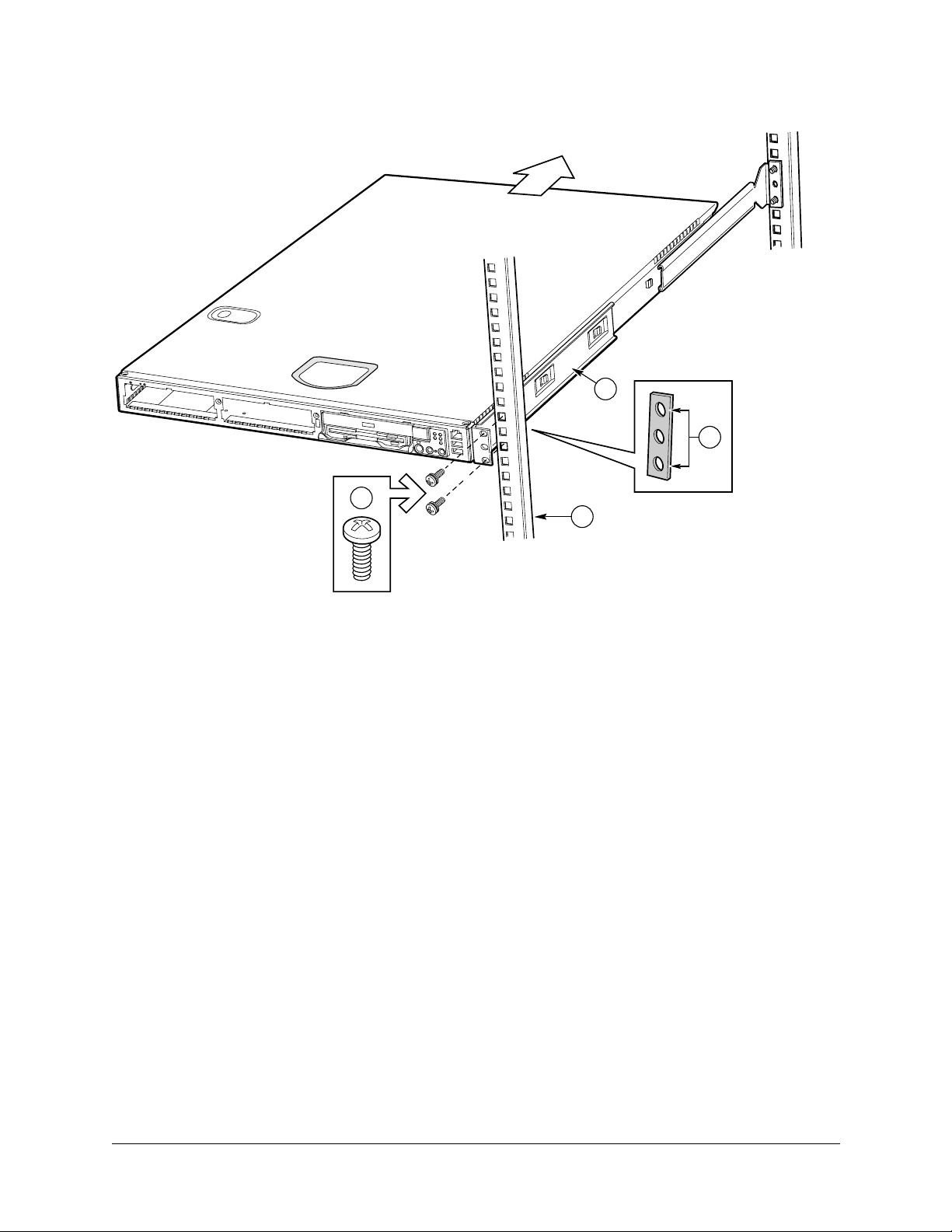
Figure 8. Attaching a Front Bracket to a Front Post
Installing the Server Using the Bracket Kit
A
D
C
A. Chassis bracket
B. Front post
C. #10-32 x 1/2-inch screw with washers
D. Nut bar
B
User Guide—Sun Cobalt LX50 Server 2-9
Page 32

Chapter 2: Installing the Server in a Rack
Install Chassis Handles
Note: The handles are required to hold the bezel on. If you will not be installing a bezel, you do
✍
1. Slide a handle (Figure 9, A) between the chassis and the chassis bracket.
2. Align the hole in the handle with the unused hole in the chassis bracket.
3. Install a spacer (B) between the handle and the chassis bracket.
4. Install and tighten screw (C) to secure the handle.
5. In the same manner, attach the other handle to the opposite side.
6. Replace the bezel.
You have completed the installation of your chassis in a four-post rack system.
Figure 9. Attaching a Chassis Handle to a Front Post
not need to install the handles.
A
B
C
A. Chassis handle
B. Spacer
C. #10-32 x 7/8-inch screw with washer
2-10 User Guide—Sun Cobalt LX50 Server
Page 33

Installing the Server Using the Bracket Kit
Mid-Mounting in a Two-Post Rack System
Attach Brackets to Chassis
1. Place a mounting bracket (Figure 10, A) along one side of the chassis in the mid-mount position.
2. Align the holes (B) in the bracket with the tabs (C) on the chassis and place the bracket against the chassis.
3. Slide the bracket as far as it will go toward the front of the chassis.
4. Fasten the bracket to the chassis using screw (D).
5. In the same manner, attach a bracket to the other side of the chassis.
Figure 10. Installing a Chassis Bracket in the Mid-mount Position
C
B
D
A. Chassis bracket in mid-mount position
B. Bracket holes
C. Chassis tabs
D. #6-32 x 3/16-inch screw
A
User Guide—Sun Cobalt LX50 Server 2-11
Page 34

Chapter 2: Installing the Server in a Rack
Attach L Brackets to Center Posts
1. Position a supplied L bracket (Figure 11, A) on the backside of the center post (C).
2. Attach the L bracket to the center post using the screws (B) supplied with your rack. Do not fully tighten at this
time.
3. In the same manner, attach an L bracket to the other center post.
Figure 11. Attaching an L Bracket to a Center Post
B
A
A. L bracket
B. Screw (supplied by your rack manufacturer)
C. Front side of typical right center post
C
2-12 User Guide—Sun Cobalt LX50 Server
Page 35

Installing the Server Using the Bracket Kit
Install Chassis in Rack
Caution: Lifting the chassis and attaching it to the rack is a two-person job. If needed, use an
appropriate lifting device. A fully loaded server weighs approximately 11.8 kg (26 lbs).
!
1. Locate one person at the front of the rack and one at the rear.
2. Position the chassis so that the L brackets (Figure 12, A) are inserted into the chassis mounting brackets (B).
3. While supporting the weight of the chassis, adjust the L brackets to fit tightly into the chassis brackets (C).
Figure 12. L Brackets Inserted into Chassis Mounting Brackets (Rear View)
B
A
C
4. Slide the chassis toward the rear of the rack until the front of the chassis mounting brackets contact the front of
the center posts.
5. Using the screws (Figure 13, C) supplied with your rack, attach the front of the mounting brackets to the front of
the center posts.
You have completed the mid-mount installation of your chassis in a two-post rack system.
User Guide—Sun Cobalt LX50 Server 2-13
Page 36

Chapter 2: Installing the Server in a Rack
Figure 13. Installing the Chassis in the Rack
A
B
C
A. Chassis bracket in mid-mount position
B. L bracket
C. Screw (supplied by rack manufacturer)
2-14 User Guide—Sun Cobalt LX50 Server
Page 37

Front-Mount-Only in a Two-Post Rack System
Warning: Your chassis rack-mount kit provides the option for mounting the system in a
two-post front-mount-only configuration. However, mounting your chassis using this option is
not recommended for use in most rack systems. In fact, the front mount method is highly
discouraged, as most racks are unable to safely and reliably support the entire weight of a
server through the front rack posts
If a front-mount-only configuration is desired, it is highly recommended that you verify
through your rack vendor that your specific rack is designed to support the excessive weight
and stresses this type of mounting configuration imposes on the rack. Structural failure of the
rack is likely if it is not designed for this type of load. A four-post or a two-post mid-mount
configuration should be used when possible.
Remove the Chassis Handles
1. Remove the bezel.
2. Remove two screws from each handle (see Figure 14).
3. Set the handles and screws aside for reattachment later.
Figure 14. Removing a Handle from the Chassis
Installing the Server Using the Bracket Kit
User Guide—Sun Cobalt LX50 Server 2-15
Page 38

Chapter 2: Installing the Server in a Rack
Attach Brackets to Chassis
1. Place a mounting bracket (Figure 15, A) along one side of the chassis in the front-mount position.
2. Align the holes (B) in the bracket with the tabs (C) on the chassis and place the bracket against the chassis.
3. Slide the bracket as far as it will go toward the front of the chassis.
4. Attach the bracket to the chassis using screw (D).
5. In the same manner, attach a bracket to the other side of the chassis.
Figure 15. Installing a Chassis Bracket in the Front-mount Position
C
B
A. Chassis bracket in front-mount position
B. Bracket holes
C. Chassis tabs
D. #6-32 x 3/16-inch screw
D
A
2-16 User Guide—Sun Cobalt LX50 Server
Page 39

Installing the Server Using the Bracket Kit
Attach L Brackets to Center Posts
1. Position an L bracket (Figure 16, A) on the backside of the center post (C).
2. Attach the L bracket to the center post using the screws (B) supplied with your rack. Do not fully tighten at this
time.
3. In the same manner, attach an L bracket to the other center post.
Figure 16. Attaching an L Bracket to a Center Post
B
A
A. L bracket
B. Screw (supplied by rack manufacturer)
C. Front flange of typical right center post
C
User Guide—Sun Cobalt LX50 Server 2-17
Page 40

Chapter 2: Installing the Server in a Rack
Install Chassis in Rack
Caution: Lifting the chassis and attaching it to the rack is a two-person job. If needed, use an
appropriate lifting device. A fully loaded server weighs about 11.8 kg (26 lbs).
!
1. Locate one person at the front of the rack and one at the rear.
2. Position the chassis so that the L brackets (Figure 17, A) are inserted into the chassis mounting brackets (B).
3. While supporting the weight of the chassis, adjust the L brackets to fit tightly into the chassis brackets (C).
Figure 17. L Brackets Inserted into Chassis Mounting Brackets (Rear View)
B
A
C
4. Slide the chassis toward the rear of the rack until the front of the chassis brackets contact the front of the center
posts.
5. Using the fasteners (Figure 18, C) supplied with your rack, attach the front of the mounting brackets to the front
of the center posts.
2-18 User Guide—Sun Cobalt LX50 Server
Page 41

Figure 18. Installing the Chassis in the Rack
C
Installing the Server Using the Bracket Kit
A
B
A. Chassis bracket in front-mount position
B. L bracket
C. Screw (supplied by rack manufacturer)
User Guide—Sun Cobalt LX50 Server 2-19
Page 42

Chapter 2: Installing the Server in a Rack
Install Chassis Handles
Note: The handles are only required to hold the bezel on. If you will not be installing a bezel,
✍
1. Slide a handle (Figure 19, A) between the chassis and the chassis bracket.
2. Align the hole in the handle with the unused hole in the chassis bracket.
3. Install a spacer (B) between the handle and the bracket.
4. Install and tighten screw (C) to secure the handle.
5. In the same manner, attach the other handle to the opposite side.
6. Replace the bezel.
Figure 19. Attaching a Chassis Handle to a Center Post
you do not need to install the handles.
A
B
C
A. Chassis handle
B. Spacer
C. #10-32 x 7/8-inch screw with washer
2-20 User Guide—Sun Cobalt LX50 Server
Page 43

Installing the Server Using the Slide Rail Kit (Optional)
Installing the Server Using the Slide Rail Kit (Optional)
The rail kit is an extra cost option, and allows you to install the Sun Cobalt LX50 server in most four-post rack and
cabinet systems.
Required Tools
• Phillips screwdriver
Kit Contents
The slide rail kit, available as optional equipment, includes the following items:
• Slide rail assemblies—qty. 2
• Rail brackets—qty. 4
• Fastener pack—qty. 1 (see Figure 20)
Figure 20. Fasteners Provided
A
B
C
D
E
A. Screws, #10-32 x ∫-inch—qty. 8
B. Screws, #6-32 x 3/16-inch—qty. 10
C. Screws, #10-32 x 7/8-inch—qty. 2
D. Nut bars—qty. 4
E. Washers—qty. 10
Remove the Inside Rails
1. Fully extend a rail assembly (Figure 21). The finger tab (D) for the extension lock is revealed.
2. Press the finger tab and slide the inside rail (C) from the middle rail (B) until it completely separates.
Note: The middle rail (B) and outer rail (A) cannot be separated.
✍
User Guide—Sun Cobalt LX50 Server 2-21
Page 44

Chapter 2: Installing the Server in a Rack
Figure 21. Fully Extended Rail Assembly
A. Outer rail
D
B. Middle rail
C. Inside rail
D. Finger tab on extension lock
A
B
C
Attach Inside Rails to Chassis
1. Position an inside rail (Figure 22, A) along one side of the chassis with the finger tab facing outward and located
closer to the rear of the chassis.
2. Align the holes (C) in the rail with the tabs (D) on the chassis and place the rail against the chassis.
3. Slide the rail as far as it will go toward the front of the chassis to engage the tabs.
4. Fasten the rail to the chassis using one screw (B) at the front of the chassis.
5. In the same manner, attach the other inside rail to the other side of the chassis.
Figure 22. Attaching an Inside Rail to the Chassis
A. Inside rail
B. #6-32 x 3/16-inch screw
D
E
C. Attachment hole
D. Attachment tab
E. Attachment hole for cable
manager (available from other
suppliers)
C
A
B
2-22 User Guide—Sun Cobalt LX50 Server
Page 45

Installing the Server Using the Slide Rail Kit (Optional)
Attach Rail Brackets to Posts
1. Using two screws (Figure 23, A) with washers, attach one nut bar (B) to the inside of the rack post. Do not
completely tighten the screws—leave them loose enough to allow insertion of the brackets in the next step.
2. Insert the slotted foot of a rail bracket between each nut bar and post.
3. Align the face of the bracket foot with the inside edge of the rack post and firmly tighten the screws.
4. Repeat steps 1 to 3 above to install the other 3 brackets (2 Front and 2 Back total). Ensure all brackets are at the
same height on the rack.
Figure 23. Attaching a Rail Bracket to a Rack Post
A. #10-32 x ∫-inch screw with washer
B. Nut bar
B
A
Attach a Rail Assembly to a Front Bracket
1. Position a rail assembly (middle and outer rails) with its black plastic end caps toward the rear of the rack and its
outer rail closest to the brackets.
2. Align the front screw hole (Figure 24, C) in the outer rail (B) with the threaded hole (D) nearest the front of the
front bracket (A) and fit the rail assembly into the front and rear brackets.
3. Slide the middle rail toward the front (E) until the access hole (F) in the middle rail is aligned with the front
screw hole (C) in the outer rail.
4. Insert screw (G) through the access hole and loosely attach the outer rail to the front bracket.
5. In a similar manner to steps 2 through 4, install a screw through a slot in the outer rail and into the rear-most
threaded hole in the front bracket. Firmly tighten this screw.
6. Firmly tighten the front screw (G) installed loosely in step 4.
7. In the same manner, attach the other rail assembly to the other side.
User Guide—Sun Cobalt LX50 Server 2-23
Page 46

Chapter 2: Installing the Server in a Rack
Figure 24. Attaching a Rail Assembly to a Front Bracket
A
D
C
B
A. Front bracket
B. Outer rail
C. Screw hole
D. Threaded hole
E. Middle rail
F. Access hole
G. #6-32 x 3/16-inch screw
G
F
E
Attach a Rail Assembly to a Rear Bracket
1. Slide the middle rail toward the front (Figure 25) until the rear bracket area is accessible.
2. Attach the rear end of the outer rail (B) to the rear bracket (A) with at least one screw (C). If possible, attach at
two places.
3. In the same manner, attach the other rail assembly to the other side.
2-24 User Guide—Sun Cobalt LX50 Server
Page 47

Figure 25. Attaching a Rail Assembly to a Rear Bracket
B
A. Rear bracket
B. Outer/middle rail assembly
C. #6-32 x 3/16-inch screw
C
Installing the Server Using the Slide Rail Kit (Optional)
A
Install the Chassis on the Rails
1. Fully extend the left and right rails (Figure 26) until the extension locks have engaged and the rails will not push
back in. The rail system is now ready to receive the chassis.
Caution: Lifting and placing the chassis in the rails is a two-person job. If needed, use an
appropriate lifting device. A fully loaded server weighs approximately 11.8 kg (26 lbs).
!
Figure 26. Rails Fully Extended
2. With the chassis front facing you, lift the chassis and carefully insert the rails attached to the chassis in the
extended rails.
3. Slide the chassis toward the rear of the cabinet until the rails lock together.
4. Depress and hold down the finger tabs (Figure 27, A) on both extension locks while sliding the chassis toward the
rear.
User Guide—Sun Cobalt LX50 Server 2-25
Page 48

Chapter 2: Installing the Server in a Rack
Figure 27. Releasing the Extension Locks
A. Finger tab on extension lock
A
5. Slide the chassis all the way into the rack until the chassis handles are against the front posts.
2-26 User Guide—Sun Cobalt LX50 Server
Page 49

Connecting the Cables
Connecting the Cables
The Sun Cobalt LX50 server has a number of connectors. Some are on the front panel; others are located on the rear
panel. This section summarizes the usage of each connector.
Front Panel Connectors
To access the front panel connectors when a front bezel is installed, grasp the bezel on the right side at the finger hole
and gently pull it towards you, unhinging it at the left until it unsnaps from the chassis. Figure 28 shows the front of
the server with the bezel removed.
Figure 28. Front Panel (bezel removed)
RJ-45 Serial 2
USB1
USB2
There are three connectors on the right side of the front panel:
• Front RJ-45 Serial 2 connector (top connector, ttyS1)
• USB 1 connector (middle connector)
• USB 2 connector (bottom connector)
The BIOS is set by default to redirect BIOS, bootup, and Linux Loader (LILO) messages to the serial port. The
default communications settings for the serial console ports on the server are:
• 9600 bps
• 8 data bits
• 1 stop bit
• No parity
• No flow control
Front RJ-45 Serial 2 Connector
The Sun Cobalt LX50 server provides two common external RJ-45 serial ports, one located on the back of the system
and the other located on the front panel.
The use of RJ-45 connectors for the serial interface is widely becoming a standard for use in the high-density server
market. The intended usage model for the RJ-45 serial connector on the back of the system is for use as an interface to
a serial port concentrator allowing for remote access to the server’s Emergency Management Port (EMP). The serial
connector on the front panel (ttyS1) can be used as a direct connect to the EMP, allowing for PC-to-PC serial
communications to perform diagnostics on a server mounted in a rack environment.
User Guide—Sun Cobalt LX50 Server 2-27
Page 50

Chapter 2: Installing the Server in a Rack
Table 7. RJ-45 Connector Usage
Mode Front Back
Modem No Yes
Serial Concentrator No Yes
PC-to-PC communication Yes Yes
Both front and back serial connectors cannot be used at the same time. Logic on the server Main Board determines
which connector is in use.
If the front serial port is in use, the rear panel serial port is automatically disabled. When the front-panel serial port
connection is removed, the system automatically re-enables the rear panel serial port.
The front RJ-45 usage model is intended for PC-to-PC serial communication only. It shares common serial signals
with the RJ-45 serial port, located on the back of the system. However, it does not support a modem, as there is no
RI signal. Instead it sets pin 5 to ground, causing logic on the Main Board to disable the rear serial port when a cable
or adapter is plugged into it.
For a direct connect or PC-to-PC serial communication, either an 8-pin RJ-45-to-DB9 adapter or a cable supporting
both DB-9 and RJ-45 connectors is necessary. Table 8 provides a pinout for the front RJ-45-to-DB9 adapter cable.
Table 8. Front RJ-45 Serial 2 Port Adapter Pinout
Signal Name RJ-45 DB9
No connect N/A 1
SIN 6 2
SOUT 3 3
DTR 2 4
GND 4
DSR 7 6
RTS 1 7
CTS 8 8
RI 5
No connect 9
a. The use of a modem on this port cannot be
supported due to the lack of the RI signal.
Note: Sun Microsystems provides an optional RJ-45 to DB9 Serial Adapter Kit (order number
✍
X5026A) for purchase. It contains three RJ-45-to-DB9 adapters. They can be plugged into the
front or rear EMP connectors. The cables are:
a
5
1
5
• DSR Peripherals cable (for rear panel connector data set ready (DSR) peripherals)
• DCD Modem cable (for rear panel connector data carrier detect (DCD) modem)
• Front EMP cable (for front Emergency Management Port)
2-28 User Guide—Sun Cobalt LX50 Server
Page 51

Connecting the Cables
USB Connectors
The USB 1 and USB 2 connectors provide USB functionality. All ports function with identical capabilities and with
the same bandwidth. The industry-standard USB v1.1 specification defines the external connectors.
Note: The USB ports are disabled until Linux is booted and the USB drivers are installed. A
✍
PS/2 keyboard is required if a keyboard is necessary for initial bootup and configuration.
Rear Panel Connectors
Figure 29. Rear Panel
RJ45 NIC 2
(eth1)*
AC Power
SCSIVideo
RJ45
NIC 1
(eth0)*
PS2 Mouse/
Keyboard
* default settings
USB 3USB 4
Back RJ45
Serial 2
There are 9 connectors on the rear panel:
• RJ-45 NIC 1 connector
• RJ-45 NIC 2 connector
• AC Power connector
• USB 3 connector
• Back RJ-45 Serial 2 connector (ttyS1)
• P/S2 mouse/keyboard connector
• SCSI connector
• Video connector
• USB 4 connector
RJ-45 NIC 1 and NIC 2 Connectors
OM11668
The server supports two 10BASE-T/100BASE-TX Network Interface Controllers (NICs). The NIC interfaces support
the following features:
• Integrated IEEE 802.3 10BASE-T and 100BASE-TX compatible PHY
• IEEE 820.3u AutoNegotiation support
• Full-duplex support at both 10 Mbps and 100 Mbps operation
• Both ports are PXE Boot capable
• Low power +3.3 V device (Wake-On-LAN support on both rear panel Ethernet ports)
User Guide—Sun Cobalt LX50 Server 2-29
Page 52

Chapter 2: Installing the Server in a Rack
AC Power Connector
This connector is where you plug in the AC power cord (a power cord is supplied appropriate to your geographic
region).
Warning: Do not attempt to modify or use the supplied AC power cord if it is not the exact
type required.
The power supply cord is the main disconnect to AC power. The socket outlet must be installed
near the equipment and readily accessible.
Rear Panel RJ-45 Serial 2 Connector
The intended use for the RJ-45 serial port, located in the back of the system, is for remote EMP communication by
connecting the port to a serial terminal concentrator. With the optional RJ-45 to DB9 Serial Adapter Kit, the serial
port can also be configured for use with a modem. Table 4, “Replaceable Components,” on page 1-4 gives ordering
information for the adapter kit. The rear serial port is traditionally referred to as COM2 (DOS, Windows), or ttyS1
(Linux).
Serial terminal concentrators use one of two serial communication standards. Some terminal concentrators require a
Data Carrier Detect (DCD) signal, while others require a Data Set Ready (DSR) signal. The server Main Board can be
configured to support either of these configurations by setting the appropriate jumper on the jumper block, located
directly behind the RJ-45 serial connector on the Main Board.
The back RJ-45 Serial 2 port can support any standard serial device. An RJ-45 connector was selected to allow for
direct support for serial port concentrators, which typically use RJ-45 connectors and are widely used in the highdensity server market to access the server management features of the server.
To give support for either of two serial configuration standards used by serial port concentrators, the J6A2 jumper
block, located on the Main Board inside the server directly behind the rear RJ-45 serial port, must be jumpered
appropriately according to which standard is desired.
Note: By default, as configured in the factory, the server Main Board has the back RJ-45 serial
✍
For serial devices that require a DSR signal (default), the J6A2 jumper block must be configured as follows: both
jumpers are in position 1 and 2. Pin 1 is denoted by an arrow directly next to the jumper block.
Figure 30. J6A2 Jumper Block Configured for DSR Signal (pin 7 connected to DSR)
J6A2
port configured to support a DSR signal that is compatible with industry-standard serial
concentrators. To change the configuration, the J6A2 jumper block must be accessed (the top
cover must be removed to access this jumper block).
Pin 1Pin 2Pin
3
J6A2 Jumper Block
(viewed from front of LX50 server)
For serial devices that require a DCD signal, the J6A2 jumper block must be configured as follows: Both jumpers are
in positions 2 and 3. Pin 1 is denoted by an arrow directly next to the jumper block. The following diagram provides
the J6A2 jumper block pinout for this configuration.
2-30 User Guide—Sun Cobalt LX50 Server
Page 53

Connecting the Cables
Figure 31. J6A2 Jumper Block Configured for DCD Signal (pin 7 connected to DCD)
Pin 1Pin 2Pin
J6A2
J6A2 Jumper Block
(viewed from front of LX50 server)
3
For those serial devices that require a DB9 type of serial connector, an 8-pin RJ-45-to-DB9 adapter must be used.
Table 9 provides the pinout required for the adapter to provide RS232 support.
Table 9. Back Serial 2 Port Adapter Pinout
RJ-45 Signal Abbr. DB9
1 Request to Send RTS 7
2 Data Terminal Ready DTR 4
3 Transmitted Data TD 3
4 Signal Ground SGND 5
5 Ring Indicator RI 9
6 Received Data RD 2
7 Data Carrier Detect/Data Set Ready DCD/DSR
8 Clear To Send CTS 8
1 or 6
a
a. The RJ-45-to-DB9 adapter used should match both the signal requirements
of the serial device and the external RJ-45 serial port. The external RJ-45
serial port provides all standard serial port signals, however having only 8
pins, Pin 7 can be manually configured to support either a DCD or DSR signal
by setting the J6A2 jumper block appropriately.
On the Sun Cobalt LX50 server, the adapters used for the
back connector cannot be used with the front connector, as
the pinout for the RJ-45 ports are different.
As an example, when using an external modem to access the server management features of the server Main Board,
you must first set the J6A2 jumper to support a DCD signal and make or choose the appropriate RJ-45-to-DB9
adapter.
Figure 32. J6A2 Jumper Block Configured for DCD Signal (pin 7 connected to DCD)
Pin 1Pin 2Pin
J6A2
J6A2 Jumper Block
(viewed from front of LX50 server)
3
User Guide—Sun Cobalt LX50 Server 2-31
Page 54

Chapter 2: Installing the Server in a Rack
If you choose to develop your own RJ-45-to-DB9 adapter, see Table 9 for the appropriate pinout configuration.
Note:
✍
USB 3 and USB 4 Connectors
The USB 3 and USB 4 connectors provide USB functionality. All ports function with identical capabilities and with
the same bandwidth. The industry-standard USB v1.1 specification defines the external connectors.
✍
PS/2 Keyboard/Mouse Connector
A single PS/2 port located on the back panel is provided to support a standard keyboard or mouse. A PS/2 Y-cable
adapter, included with the Sun Cobalt LX50 server, allows simultaneous use of the PS/2 keyboard and mouse. Such
cable adapters are also commonly available at most computer stores.
• Only the back Serial 2 port has modem support
• Sun Microsystems provides an optional RJ-45 to DB9 Serial Adapter Kit (order number
X5026A) that can be purchased that contains all three RJ-45-to-DB9 adapters:
• DSR Peripherals cable (for rear panel data set ready (DSR) peripherals
• DCD Modem cable (for rear panel data carrier detect (DCD) modem)
• Front EMP cable (for front panel Emergency Management Port)
Note: The USB ports are disabled until Linux is booted and the USB drivers are installed. A
PS/2 keyboard is required if a keyboard is necessary for initial bootup and configuration.
Note: The USB ports are disabled until Linux is booted and the USB drivers are installed. A
✍
SCSI Connector
The Sun Cobalt LX50 server includes an onboard Adaptec dual channel Ultra-160 SCSI controller capable of
controlling up to three internally mounted SCSI drives and 15 external SCSI drives at rates up to 160 MB/s. The
onboard SCSI controller is connected to a SCSI backplane board inside the server using a 68-pin SCSI cable. The
SCSI backplane provides connections for up to three internally mounted SCA LVDS SCSI drives with standard
80-pin SCA connectors. Channel B is used exclusively by internal drives while channel A is used for connecting to
external SCSI devices by means of a rear panel high-density SCSI connector. The connector supports a standard highdensity 68-pin connector. Use only shielded Ultra-160 LVDS rated cables for connection to external SCSI drives.
Video Connector
The Sun Cobalt LX50 server provides an ATI Rage XL PCI graphics accelerator, along with 8 MB of video SDRAM
and support circuitry for an embedded SVGA video subsystem. The SVGA subsystem supports a variety of modes,
up to 1600 x 1200 resolution in 8/16/24/32 bpp modes under 2D, and up to 1024 x 768 resolution in 8/16/24/32 bpp
modes under 3D. It also supports both CRT and LCD monitors with up to 100 Hz vertical refresh rates. All of these
capabilities depend on software support.
The server provides a standard 15-pin VGA connector and supports disabling of the on-board video through the BIOS
Setup menu or when a plug-in video card is installed in any of the PCI slots.
PS/2 keyboard is required if a keyboard is necessary for initial bootup and configuration.
2-32 User Guide—Sun Cobalt LX50 Server
Page 55

Chapter 3
Controls and Indicators
This chapter describes the control pushbuttons and LED indicators on the Sun Cobalt™ LX50 server. All of the
descriptions in this chapter pertain to buttons and indicators that are usable and visible from the outside of the chassis.
For information about the controls and indicators on the server Main Board, see the additional information contained
in Chapter 6, “Troubleshooting the Server.”
The pushbuttons and LEDs on the front and rear panels are described in the following sections.
Front Panel LEDs and Pushbuttons
The front panel contains the pushbuttons and LEDs shown in Figure 33. Note that the illustration has the bezel
removed.
Figure 33. Front Panel Pushbuttons and LEDs (bezel removed)
NIC1 LED
NIC2 LED
Power LED
System Status/Fault LED
Hard Disk Drive Activity LED
System ID LED
Power Button
Reset Button
NMI Button (recessed, not implemented)
OM11670D
System ID Button
User Guide—Sun Cobalt LX50 Server 3-1
Page 56

Chapter 3: Controls and Indicators
LEDs
• Power LED (green). This LED is controlled by software. It flashes when the server is first powered up and
changes to steady on when the server firmware has completed the power-up self-test (POST).
• NIC1 and NIC2 LEDs (green). These LEDs blink to reflect network data activity.
• System Status/Fault LED (green/amber). This LED can assume different states (green, amber, steady, blinking)
to indicate critical, non-critical, or degraded server operation. See “Front-Panel System Status LED” on page 6-3
for more details regarding this LED.
• Hard Disk Drive Activity LED (green). The Drive Activity LED on the front panel is used to indicate drive
activity from the onboard SCSI controller. The server Main Board also provides a header, giving access to this
LED for add-in IDE or SCSI controllers.
• System ID LED (blue). The blue System Identification LED is used to help identify a system for servicing when
it is installed within a high density rack or cabinet that is populated with several other similar systems. The
System ID LED is illuminated when the system ID button, located on the front panel, is pressed. If activated by
the front panel pushbutton, the LED remains on until the pushbutton is depressed again. The LED also
illuminates when the server receives a remote System Identify command from a remote management console. In
this case, the LED turns off after a timeout period. An additional blue System ID LED on the Main Board is
visible through the rear panel. It mirrors the operation of the front panel LED.
Pushbuttons
• Power/Sleep button. This pushbutton is used to toggle the system power on and off. This button is also used as a
sleep button for operating systems that follow the ACPI specification. Sun Linux configures the power button to
the instant off mode.
• Reset button. Depressing this pushbutton reboots and initializes the system.
• NMI button. Pushing this recessed pushbutton causes a non-maskable interrupt to occur; however, NMI event
trapping is not implemented in Sun Linux 5.0.
• System ID button. This pushbutton toggles the state of the front panel ID LED and the server Main Board ID
LED. The Main Board ID LED is visible through the rear of the chassis and allows you to locate a particular
server from behind a rack of servers.
3-2 User Guide—Sun Cobalt LX50 Server
Page 57

Rear Panel LEDs
Rear Panel LEDs
The rear panel contains the LEDs shown in Figure 34.
Figure 34. Rear Panel LEDs
Network Connection/Activity
LEDs (green)
• Network Connection/Activity LEDs (green). The green LED, when illuminated, indicates a valid network
connection. It also indicates, when blinking, that there is transmit or receive activity.
• Network Speed LEDs (yellow). The yellow LED indicates 100 Mbps operation when lit and 10 Mbps operation
when off.
Network Speed
LEDs
(yellow)
(green/amber, on Main Board)
System ID LED
(green, on Main Board)
Four POST LEDs
System ID LED
(blue, on Main Board)
Power Supply LED
OM11668
• POST LEDs (multi-color). To help diagnose power-on self test (POST) failures, a set of four bi-color diagnostic
LEDs is located on the back edge of the server Main Board. These LEDs are visible through holes in the rear
panel. Each of the four LEDs can have one of four states: Off, Green, Red, or Amber. For detailed information on
these LEDs, see “POST LED Indicators” on page 6-12.
• System ID LED (blue). This LED is located on the Main Board and is visible through holes in the rear panel. It
can provide a mechanism for identifying one system out of a group of identical systems. This can be particularly
useful if the server is used in a rack-mount chassis in a high-density, multiple-system application. The LED is
activated by depressing the front panel System ID pushbutton or if the server receives a remote System Identify
command from a remote management console. If activated by the front panel pushbutton, the LED remains on
until the pushbutton is depressed again. When the LED illuminates due to a remote System Identify command,
the LED turns off after a timeout period. An additional blue System ID LED is located on the front panel that
mirrors the operation of the rear Main Board LED.
• Power Supply LED (green/amber). This is a bi-color LED that can be on, off, green, amber, or blinking, or
combination thereof. See “Rear Panel Power Supply Status LED” on page 6-4 for more detailed information.
User Guide—Sun Cobalt LX50 Server 3-3
Page 58

Chapter 3: Controls and Indicators
3-4 User Guide—Sun Cobalt LX50 Server
Page 59

Chapter 4
Powering On and Configuring the Server
This chapter explains how to use the Power On switch to apply power to the server, boot to the Sun Linux 5.0
operating system, use the serial console, update system software, and validate the operation of the Sun Cobalt™
LX50 server. The chapter contains these sections:
• “Setting the Jumper Positions” on page 4-1
• “Powering On” on page 4-1
• “Clearing CMOS” on page 4-2
• “Booting Up” on page 4-2
• “Linux Loader (LILO) Menu Options” on page 4-6
• “Configuring an External Serial Console” on page 4-7
• “Using the Service Partition Menu” on page 4-9
• “Restarting and Shutting Down” on page 4-26
Setting the Jumper Positions
Two jumpers on the Main Board are preset by default to the positions that satisfy most serial port configurations.
They are located at the rear of the server, on the Main Board, next to the rear RJ-45 serial 2 connector. The two
jumpers are on the jumper block labeled J6A2. The top cover of the server must be removed to access these jumpers.
If you need to change these jumpers from their factory default positions, see “Rear Panel RJ-45 Serial 2 Connector”
on page 2-30.
Powering On
Caution: The power switch on the front of the server is an On/Off switch, but it does not
isolate the equipment from the AC power being supplied through the AC power cord.
!
The location of the switch is shown in Figure 35.
Figure 35. Power and Reset Switches on the Front Panel
Front Panel Power On/Off Switch Reset Switch
User Guide—Sun Cobalt LX50 Server 4-1
Page 60

Chapter 4: Powering On and Configuring the Server
Pushing the switch sends a signal to monitoring circuitry inside the server. The switch does not directly control
high-voltage AC; it controls only low-voltage signals. When the monitoring circuitry detects that the button has been
depressed, it activates the power supply and powers up the server. Likewise, when the server is powered up, pushing
the switch powers the server down.
The main method for isolating the server from all high voltage is to physically remove the AC power cord. If the
power cord is not removed, the only other way to isolate the server from high voltage is to open all external circuit
breakers that supply AC voltage to the equipment.
Caution: As shipped, the Sun Cobalt LX50 server does not have Advanced Configuration and
Power (ACPI) enabled in the Sun Linux™ 5.0 kernel and, as a result, the front panel power
!
switch operates as a normal power switch. In this configuration, press the switch once and
power comes on, press again and the power goes off. It is recommended that you use the
standard Sun Linux 5.0 shutdown command before you power down the system using the
switch. Activate the front panel switch to remove power only when Linux has completed the
shutdown process and has halted.
Should you elect to use an ACPI-enabled Linux kernel and run the ACPI daemon (acpid), the
behavior of the front panel switch will change to support the standard “soft-off” capability.
That is, when the server is on and the power switch is pressed, the OS is notified and begins a
graceful shutdown. Additionally, with ACPI enabled and the server on, pressing the power
button for longer than four seconds forces an immediate (non-graceful) shutdown.
Clearing CMOS
It may be necessary to clear CMOS memory in order to restore the default BIOS passwords required to boot the
server (user) or access setup functions (supervisor), as well as the default BIOS settings. To clear CMOS, follow these
steps:
1. Power down the server
2. Push and hold the reset button for at least four seconds
3. While continuing to depress the reset button, push the server power button to power up the server
4. After power has been applied, release the reset button
Booting Up
As soon as power is applied to the server, the bootup process begins. Boot messages are sent to either a monitor
attached to the video port, or to a serial console attached to the front or rear RJ-45 serial console ports.
The server is configured by default to initially send BIOS and kernel messages to both the serial console and the video
port. However, when the boot process reaches the Linux Loader (LILO) point, the messages and screens are sent only
to the video port. After bootup is finished, the configuration can be changed to send all messages to the serial console
(see “Configuring an External Serial Console” on page 4-7).
Boot Options
The first bootup screen is shown in Figure 36.
4-2 User Guide—Sun Cobalt LX50 Server
Page 61

Figure 36. First BIOS Bootup Screen
At the bottom of the screen, you are given the option to press the following function keys:
Booting Up
• F2 to enter the BIOS Setup Utility
• F4 for the Service Partition (a DOS partition allowing setup configuration and server testing)
• F12 to boot from the Network
BIOS Setup Utility <F2>
Press F2 to enter the BIOS Setup Utility. The main BIOS Setup Utility screen shown in Figure 37 appears.
Figure 37. BIOS Setup Utility Main Screen
Caution: Changing the BIOS settings may cause undesirable effects, and in some cases may
disable the server. Be very careful before changing the BIOS configuration.
!
User Guide—Sun Cobalt LX50 Server 4-3
Page 62

Chapter 4: Powering On and Configuring the Server
It is important to note the default boot sequence. The boot sequence is accessed by using the right arrow key to select
the Boot menu item on the top of the BIOS screen, then pressing Enter. The boot sequence is then displayed. The
default boot sequence is as shown in Figure 38. Use this screen to restore the boot sequence, if necessary.
Figure 38. Default Boot Sequence
You can always restore all of the default BIOS settings by scrolling to the Exit menu item along the top of the screen.
The BIOS Setup screen then appears as shown in Figure 39.
Figure 39. BIOS Setup Utility Exit Screen
To restore all of the default settings, scroll to “Load Setup Defaults” and press Enter, then select Yes at the prompt and
press Enter again. Now press F10 to save the settings and exit.
When you exit the BIOS setup utility, the bootup process continues.
4-4 User Guide—Sun Cobalt LX50 Server
Page 63
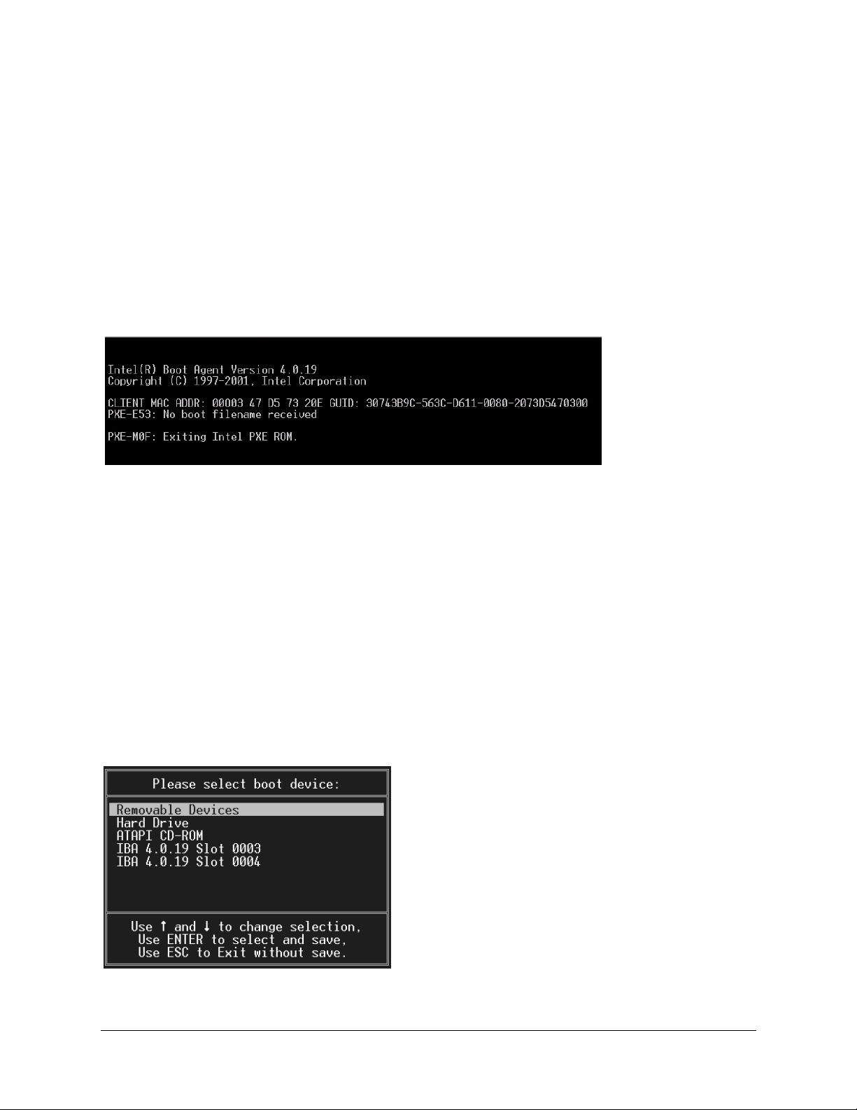
Booting Up
Service Partition <F4>
Press F4 to boot to the service partition. This partition allows you to set configuration parameters and run diagnostics.
See “Using the Service Partition Menu” on page 4-9 for more details.
When you are finished using the service partition, you must depress the Ctrl-Alt-Delete keys simultaneously to
reboot.
Network <F12>
Press F12 to boot from the network. The server software then looks for a valid boot file name on the network. If it
finds such a file name, it boots from the network. If it cannot find a valid file name, it gives up and continues to boot
from the hard disk. Figure 40 is an example of how the screen appears when booting from the network fails.
Figure 40. Network Boot Failed Screen
PXE (Pre-boot Execution Environment) is a method by which the server can booted from a remote server. This allows
the system to boot without any knowledge of the Operating System on the server. The PXE environment uses DHCP
to obtain network addresses. PXE is primarily used for loading operating systems, configuring the system, or burn-in
type testing. PXE booting will only work if a properly configured PXE server is available.
Choose Boot Device <ESC>
Press the Esc key to go to the boot device selection menu. This menu, shown in Figure 41, allows you to select the
device from which the system will boot. To select a boot device, scroll to the desired device and press Enter;
otherwise, press Esc to exit without changing the boot device.
Note : When you select a boot device with the menu shown in Figure 41, it only affects the
✍
Figure 41. Boot Device Selection Menu.
current boot. Subsequent boots revert to the device stored in the BIOS default settings.
User Guide—Sun Cobalt LX50 Server 4-5
Page 64

Chapter 4: Powering On and Configuring the Server
Linux Loader (LILO) Menu Options
The bootup process eventually takes you to the Sun Linux loader screen. The Sun Cobalt LX50 server uses the
standard LILO boot loader. You initially have four options:
• linux
• linux-serial
• linux-up
• linux-up-serial
In all cases, the serial ports on the front and rear panels are operational but their modes change. When you choose any
of the serial boot options (linux-serial or linux-up serial), the serial port (ttyS1) becomes the default console device.
The standard keyboard/mouse/VGA port becomes just a standard tty device. Conversely, when you choose any of the
non-serial options (linux or linux-up), the standard Linux console is the keyboard/mouse/VGA port and the serial port
becomes a standard Linux login terminal.
If you do nothing, the default option (linux) is automatically selected after about five seconds. This option is also
selected if you press Enter before the five seconds is up. You may also manually select one of the options. To do this,
press the Tab key. Pressing Tab brings up the following prompt:
1
1
boot:
You may now type any of the options after the prompt, for example:
boot: linux
boot: linux-serial
boot: linux-up
boot: linux-up-serial
After you make your selection, Linux continues to boot.
, or
, or
, or
Initialization Sequence
At this point, you can do the following:
• Set Up Hardware Devices
• Log On and Create a Password (the default login is
• Reconfigure the Console
• Configure X
• Configure Serial
• Configure Video
• Configure Default Services
• Configure New Services
• Set Up Linux Applications
• Set Up Sun Linux Applications
and the default password is
root
admin
)
Please refer to the Sun Linux 5.0 User Guide for more details.
1. linux-up is Linux uniprocessor, and can be run on a dual-processor server. Linux runs faster if you have a
single CPU and you choose one of the “up” options.
4-6 User Guide—Sun Cobalt LX50 Server
Page 65

Configuring an External Serial Console
Configuring an External Serial Console
There are two RJ-45 serial console ports on the Sun Cobalt LX50 server, one on the front panel and one on the rear
panel, as shown in Figure 42. You can direct boot messages to a serial console (for example, a laptop running
HyperTerminal).
Figure 42. Front- and Rear-Panel Serial Console Ports
Front Panel Serial Console Port
OM11670A
Serial Console Port (ttyS1)
The default communications settings for the serial console ports on the server are:
• 9600 bps
• 8 data bits
• 1 stop bit
• No parity
• No flow control
✍
Only one of the serial console ports can be used at a time. In Chapter 2, “Installing the Server in a Rack,” see “Front
RJ-45 Serial 2 Connector” on page 2-27, and “Rear Panel RJ-45 Serial 2 Connector” on page 2-30 for details on how
their ports are configured.
Rear Panel
Note: When Linux starts communicating over the serial port, it requires hardware flow control
to be enabled.
You can connect to the port if you have an adapter cable that has an RJ-45 connector at one end
and a DB9 connector at the other, wired in accordance with Table 8, “Front RJ-45 Serial 2 Port
Adapter Pinout,” on page 2-28 of Chapter 2, “Installing the Server in a Rack.” You can then
connect the COM1 port of a PC or laptop to the serial console using the adapter cable and use
HyperTerminal (or a similar application) to communicate with the server.
An ANSI 500 terminal emulator is needed to have the display appear properly during BIOS
setup and when using the diagnostic CD or Service Partition tools.
OM11668A
The intended usage model for the RJ-45 serial connector on the back of the server is for use as an interface to a serial
port concentrator, allowing for remote access to the server’s Emergency Management Port (EMP). The serial
connector on the front panel can be used as a direct connect to the EMP, allowing for PC-to-PC serial
communications to diagnostics on a server mounted in a rack environment.
User Guide—Sun Cobalt LX50 Server 4-7
Page 66

Chapter 4: Powering On and Configuring the Server
The server is initially configured to send all the initial BIOS and kernel bootup messages to both the serial console
and the VGA port.
When the boot process gets to the Linux loader, the boot screen information is sent both to the VGA and serial ports,
and you are presented with the following choices:
• linux
• linux-up
• linux-serial
• linux-up-serial
To direct all of the messages to the serial console, use the Tab key and choose one of the serial options.
Note: The serial port is enabled for all boot options, but the standard Linux console device
✍
changes, depending on which boot option is selected (see “Linux Loader (LILO) Menu
Options” on page 4-6 for more details).
4-8 User Guide—Sun Cobalt LX50 Server
Page 67

Using the Service Partition Menu
Using the Service Partition Menu
When you press F4 at the initial bootup screen, the Service Partition Menu appears (see Figure 43).
Figure 43. Service Partition Menu
There are three main menu items across the top of this screen:
• Create Diskettes
• System Utilities
• Quit to DOS
User Guide—Sun Cobalt LX50 Server 4-9
Page 68

Chapter 4: Powering On and Configuring the Server
Create Diskettes
Pressing Enter with the Create Diskettes menu item highlighted brings up the submenu shown in Figure 44.
Figure 44. Create Diskettes Submenu
You can use this submenu to create various types of standalone diskettes that you can use to boot servers and run
particular tests, utilities, or Flash the BIOS instead of using the service partition menu.
The following disks can be created:
• System Setup Utility: choosing this option creates two diskettes that allow you to run the System Setup Utility
(SSU) in the same way that you run it from the service partition or from the diagnostic CD. With the two diskette
set, you can perform the functions described in “Run System Setup Utility” on page 4-12.
• FRU/SDR Load Utility: choosing this option creates one diskette that allows you to run the FRU/SDR Load
Utility in the same way that you run it from the service partition or from the diagnostic CD. With the diskette,
you can perform the functions described in “Run Field Replaceable Unit/System Data Record (FRU/SDR)
Update2” on page 4-25
• Platform Confidence Test: choosing this option creates one diskette that allows you to run the Platform
Confidence Test in the same way that you run it from the service partition or from the diagnostic CD. With the
diskette, you can perform the functions described in “Run System Diagnostic Test” on page 4-15
• Create BIOS Diskette: choosing this option creates one diskette. You may use this diskette to update the BIOS of
any server.
• Create HSC Diskette: choosing this option creates one diskette that allows you to update the HSC firmware.
• Create BMC Diskette: choosing this option creates one diskette that allows you to update the BMC firmware
4-10 User Guide—Sun Cobalt LX50 Server
Page 69

Using the Service Partition Menu
System Utilities
Pressing Enter with the System Utilities menu item highlighted brings up the submenu shown in Figure 45.
Figure 45. System Utilities Submenu
The following submenus are available:
• Run System Setup Utility
• Run System Diagnostic Test
• Run BMC Firmware Update
• Run HSC Firmware Update
• Run FRU/SDR Update
• Run BIOS Boot Block Update (reboot required)
• Run BIOS Update (reboot required)
• Reboot to Service Partition
• Reboot System
User Guide—Sun Cobalt LX50 Server 4-11
Page 70

Chapter 4: Powering On and Configuring the Server
Run System Setup Utility
The built-in service partition on the hard disk of the Sun Cobalt LX50 server allows you to perform server
management, configuration and validation testing. To bring up the service partition, reboot and press the <F4>
function key when the first BIOS screen appears.
Note: Any configuration changes (CPU, memory, hard disk, add-in PCI cards and so forth)
✍
Select Run System Setup Utility to run system setup. The System Setup Utility main window appears
(see Figure 46).
Figure 46. SSU Main Window
causes the server to revert to its factory-default state, regardless of how the server boot options
have been set up using SSU or the BIOS setup.
The System Setup Utility (SSU) allows you to configure the following:
• User Preferences
• Boot devices
• Security
Setting User Preferences
Because the server supports running the SSU over a serial console, all of the menus work in text mode only.
4-12 User Guide—Sun Cobalt LX50 Server
Page 71

Using the Service Partition Menu
Configuring Boot Devices
The Multiboot Add-in (MBA) feature of the SSU allows you to select the boot order for all bootable peripheral
devices. To select the boot device priority, double-click the MBA Boot Devices menu item in the Available Tasks pane
of the SSU main window. The Multiboot Options Add-in window appears (see Figure 47).
Figure 47. Multiboot Add-in Window
To change boot priorities, select a boot device and use the Move Down and Move Up buttons to move the device boot
priority.
Note : This menu allows you to change the boot order without going into the BIOS setup.
✍
Configuring Security
The Password Authorization feature of the SSU allow you to set BIOS passwords and other security options. To
configure server security, double-click the PWA Security menu item in the Available Tasks pane of the SSU main
window. The main Security window appears (see Figure 48).
Note : This menu allows you to change the security settings without going into the BIOS setup.
✍
User Guide—Sun Cobalt LX50 Server 4-13
Page 72

Chapter 4: Powering On and Configuring the Server
Figure 48. Security Main Window
Use the Admin Password, User Password, and Options buttons to configure the security options.
The System Setup Utility (SSU) allows you to manage the following:
• System Event Log (SEL)
• System Data Records (SDR)
• Field Replaceable Units (FRU)
• Platform Events
Managing the System Event Log
The server maintains a system event log in non-volatile memory. The log can be viewed and cleared using the SSU.
To manage the log, double-click the SEL Manager menu item on the Available Tasks pane of the main SSU window.
The System Event Log appears, and you can use the menu bar at the top of the log window to save the log, open a log,
clear the log, or reload the log.
Managing the Sensor Data Records
The Sensor Data Record (SDR) Manager allows you to view the current sensor data for the system, save the SDR data
to a file, and view SDR information previously saved to a file. The SDR data is saved in standard SDR format. To
manage the SDR data, double-click the SDR Manager menu item on the Available Tasks pane of the main SSU
window. The SDR Manager main window appears, and you can use the menu bar at the top of the window to manage
SDR data.
Managing the Field Replaceable Units
The Field Replaceable Unit (FRU) Manager allows you to view the FRU information stored in the managed server.
The FRU records contain information about the system components, such as manufacturer’s name, product name,
part number, version number and asset tags. This information may prove useful when troubleshooting faults in the
server.
To manage the FRUs, double-click the FRU Manager menu item on the Available Tasks pane of the main SSU
window. The FRU Manager main window appears, and you can use the menu bar at the top of the log window to
manage FRU information.
4-14 User Guide—Sun Cobalt LX50 Server
Page 73

Using the Service Partition Menu
Managing Platform Events
The Platform Event Manager (PEM) allows you to configure and manage Platform Event Paging (PEP), Baseboard
1
Management Controller Local Area Network (BMC-LAN) Configuration, and the Emergency Management Port
(EMP).
To use PEM, double-click the Platform Event Manager menu item on the Available Tasks pane of the main SSU
window. The Platform Event Manager main window appears. You can click on the buttons in this window to perform
platform management.
Run System Diagnostic Test
Select Run System Diagnostic test to bring up the Platform Confidence Test menu (see Figure 49).
Figure 49. Platform Confidence Test Menu
You can use this menu to perform the following tests:
• Quick Test
• Comprehensive Test (DEFAULT)
• Comprehensive Test With Continuous Looping
All test results are saved in the
RESULT.LOG
file of the current directory, which is normally
overwritten for each test.
1. Baseboard refers to the Main Board in the server.
User Guide—Sun Cobalt LX50 Server 4-15
C:\PCT.
This file is
Page 74

Chapter 4: Powering On and Configuring the Server
Quick Test
This test performs a quick test of the CPU(s), DIMM memory, CPU cache memory, and hard disk drives. It is not a
complete test of these units.
Quick Test takes from 2 to 5 minutes, depending on the amount of DIMM memory installed. The following test
modules are run during Quick Test:
• Power On Self Test (POST)
• CPU Test(s)
• Symmetric Multiprocessing (SMP) Processor 0 Test
• Symmetric Multiprocessing (SMP) Processor 1 Test
• Hard Disk Drive Test(s)
• Cache Memory Test(s)
• DIMM Memory Test
To run the Quick Test, follow this procedure:
1. Select Quick Test using the arrow keys and press Enter.
The initial testing produces a screen similar to the one shown in Figure 50. This phase of the testing determines
your server configuration.
Figure 50. Platform Confidence Quick Test (first screen)
More screen entries appear as the test progresses. Eventually the screen shown in Figure 51 appears.
4-16 User Guide—Sun Cobalt LX50 Server
Page 75

Using the Service Partition Menu
Figure 51. Platform Confidence Quick Test Hardware Test Configuration (first screen)
This screen indicates the hardware configuration that has been determined from the initial tests.
2. Press any key to display the remaining results of the configuration testing (see Figure 52).
Figure 52. Platform Confidence Quick Test Hardware Test Configuration (second screen)
3. If the hardware configuration does not match the configuration of your server, press the Ctrl and Break keys
simultaneously.
You are prompted to check all the cables and your server configuration, then you are exited to the Platform
Confidence Test main menu.
4. If the configuration is correct, press Enter to continue.
User Guide—Sun Cobalt LX50 Server 4-17
Page 76

Chapter 4: Powering On and Configuring the Server
Several entries are displayed and scroll past on the screen, showing the test progress (see Figure 53).
Figure 53. Platform Confidence Quick Test Progress
When the testing is done, the results are summarized (see Figure 54).
Figure 54. Platform Confidence Quick Test Results
4-18 User Guide—Sun Cobalt LX50 Server
Page 77

5. Press any key to see the analog sensor readings (see Figure 55).
Figure 55. Platform Confidence Quick Test Sensor Readings (first screen)
Using the Service Partition Menu
6. Press any key to see the remaining sensor readings (see Figure 56).
Figure 56. Platform Confidence Quick Test Sensor Readings (second screen)
7. Press any key to return to the main Platform Confidence Test menu.
User Guide—Sun Cobalt LX50 Server 4-19
Page 78

Chapter 4: Powering On and Configuring the Server
To view the test results, follow this procedure:
1. Return to the System Utilities submenu (see Figure 45 on page 4-11) and exit to DOS.
2. Change directories to:
C:\PCT
3. Type the following command:
Type RESULT.LOG | more
A portion of the RESULT.LOG file is displayed each time you press a key. In this way, you can see the results,
which are divided into the following sections:
• BIOS ID
• Hardware Configuration
• Test Summary
• Analog Sensor Readings
RESULT.LOG file is overwritten each time you run a test. A sample of the RESULT.LOG file is shown in
The
Figure 57.
Figure 57. Sample RESULT.LOG
4-20 User Guide—Sun Cobalt LX50 Server
Page 79

Figure 58. Sample RESULT.LOG (continued)
Using the Service Partition Menu
User Guide—Sun Cobalt LX50 Server 4-21
Page 80

Chapter 4: Powering On and Configuring the Server
Figure 59. Sample RESULT.LOG (continued)
4-22 User Guide—Sun Cobalt LX50 Server
Page 81

Using the Service Partition Menu
Comprehensive Test
This test fully exercises and tests the server system. The test takes approximately 15 to 20 minutes to execute,
depending on the amount of memory installed. The following test modules are run during the Comprehensive Test:
• Power On Self Test
• CPU Test(s)
• Cache Memory Test(s)
• Math Coprocessor Test(s)
• Symmetric Multiprocessing (SMP) Processor 0
• Symmetric Multiprocessing (SMP) Processor 1
• DIMM Memory Test
• Serverworks HE-SL Chipset Test
• Primary Interrupt Controller Test
• Programmable Interrupt Timer Test
• Keyboard Test
• Hot Swap Controller Test
• Real Time Clock Test
• PCI Bus Controller Test
• Universal Serial Bus Controller Test
• Super I/O Controller Test
• DMA Controller Test
• Baseboard Management Controller Test
• Comm Port 1 Controller Test
• Comm Port 2 Controller Test
• Adaptec SCSI Controller Test
• Parallel Port Controller Test
• Floppy A Controller Test
• ATI Video Adapter Test
• CD-ROM Controller Test
• Hard Disk Drive Controller and Drives Test
To run the Comprehensive Test, follow this procedure:
1. Select Comprehensive Test using the arrow keys and press Enter.
The initial testing determines your server configuration, and produces screens similar to those shown in
Figure 50, Figure 51, and Figure 52.
2. When you are prompted about the configuration of the server, if the hardware configuration does not match the
configuration of your server, press the Ctrl and Break keys simultaneously.
You are prompted to check all the cables and your server configuration, then you are exited to the Platform
Confidence Test main menu.
User Guide—Sun Cobalt LX50 Server 4-23
Page 82

Chapter 4: Powering On and Configuring the Server
3. If the configuration is correct, press Enter to continue.
Several entries are displayed and scroll past on the screen, showing the test progress (see Figure 60). The
information is much more detailed than that displayed for the Quick Test.
Figure 60. Platform Confidence Comprehensive Test Progress
When the testing is done, the results are summarized (see Figure 61).
Figure 61. Platform Confidence Comprehensive Test Results
4. Press any key to see the remaining test results.
5. Press any key to see the analog sensor readings (similar to the screens shown in Figure 55 and Figure 56).
6. Press any key to return to the main Platform Confidence Test menu.
7. You can view the
RESULT.LOG file in a similar fashion to that previously explained.
4-24 User Guide—Sun Cobalt LX50 Server
Page 83

Using the Service Partition Menu
Comprehensive Test With Continuous Looping
This test performs the same test as the Comprehensive Test, but runs continuously until stopped. To stop the testing
and display the test pass count, press Ctrl + Break. The number of test loops executed is shown as “Pass Count = n” at
the upper right side of the screen.
The run time for this test is approximately 15 to 20 minutes per pass, depending on the amount of memory installed.
Note: The Comprehensive Test should be run after changing any FRU, CRU, or adding an
✍
optional component.
Run Baseboard1 Management Controller (BMC) Firmware Update
Use this menu selection to update the Baseboard Management Controller (BMC) firmware. The BMC code resides
both on the Diagnostics CD and on the Service Partition in the C: /BMC directory.
2
Run HSC Firmware Update
Use this menu selection to update the hard disk controller firmware. The HSC code resides both on the Diagnostics
CD and on the Service Partition in the C: /HSC directory.
Run Field Replaceable Unit/System Data Record (FRU/SDR) Update
Use this menu item to re-inventory the FRUs and System Data Records (SDR) on the Sun Cobalt LX50 server. You
can also use this selection to modify the asset tag and the chassis serial number. These are both customer optional
fields that are left blank when the system is shipped from the factory.
When you run the update, make sure you choose the following at the appropriate prompt:
• Main Board supports SCSI drives
• SR1200 chassis
The FRU/SDR code resides both on the Diagnostics CD and on the Service Partition in the C: /FRUSDR directory.
Run BIOS Update (reboot required)
Use this menu item to update the BIOS Boot block in the event that the boot block becomes corrupted. Use this menu
item to also update the BIOS in the event that the BIOS becomes corrupted or if you want to set the BIOS settings
back to their defaults. A reboot occurs automatically after the update is complete. The BIOS code resides both on the
Diagnostics CD and on the Service Partition in the C: /BIOS directory.
2
2
Reboot to Service Partition
Selecting this menu item causes a reboot to the service partition.
Reboot System
Choosing this menu item causes a reboot, maintaining normal boot ordering.
1. The baseboard refers to the server Main Board
2. The update files are on the hard drive service partition. This allows accessibility to the partition from within
Linux, since it is mounted as /diag at the root. The latest firmware updates can be downloaded by means of
FTP onto the /diag partition so that you can simply reboot and update the system
User Guide—Sun Cobalt LX50 Server 4-25
Page 84

Chapter 4: Powering On and Configuring the Server
Restarting and Shutting Down
You may restart or shut down the Sun Cobalt LX50 server using software or hardware.
Software Mechanisms
The following software mechanisms are available:
• Ctrl-Alt-Del key combination: use this to shut down the operating system and restart the server at any time. This
works regardless of whether you are logged in or not when in text mode. When running Gnome or XWindows
desktops, you must log in as root first. The Ctrl-Alt-Del key combination works for both PS/2 and USB
keyboards.
• shutdown -h now: type this to initiate an orderly shutdown and halt the server. You may then press the Power
button to safely power off the server.
• shutdown -r now: type this to initiate an orderly shutdown and reboot of the server.
Hardware Mechanisms
The following hardware mechanisms are available:
• Press the Reset button: the server is immediately forced to restart. However, you may lose data.
• Press the Power button: the server is immediately forced to power down. However, you may lose data.
Important: These hardware mechanisms are not recommended and should be used only as a
☞
last resort.
4-26 User Guide—Sun Cobalt LX50 Server
Page 85

Chapter 5
Maintaining the Server
This chapter describes how to replace components in the Sun Cobalt™ LX50 server after it has been set up. It
contains the following sections:
• “Tools and Supplies Needed” on page 5-2
• “Determining a Faulty Component” on page 5-2
• “Safety: Before You Remove the Cover” on page 5-2
• “Removing and Replacing the Cover” on page 5-3
• “Customer Replaceable Unit (CRU) Procedures” on page 5-4
• “Field Replaceable Unit (FRU) Procedures” on page 5-15
Note : The procedures in this chapter for servicing field replaceable faulty components are for
✍
the attention of qualified service engineers only. If a Field Replaceable Unit (FRU) needs
replacement, contact your local Sun Sales representative who will put you in contact with the
Sun Enterprise Service branch for your area. You can arrange to return the system to Sun for
repair under the terms of your warranty. Or, if under a Sun Service agreement, the FRU will be
replaced by a Sun Service engineer. If a Customer Replaceable Unit (CRU) needs replacement,
you can either request a replacement part from Sun or return the entire unit for repair. All parts
replaced under the system warranty must be returned to Sun within 30 days of receipt of the
replacement part.
✍
Note : When working on a server, you may want to turn on the blue System ID LED to identify
the server that is being worked on. See “LEDs” on page 3-2 for instructions on how to turn on
this LED.
User Guide—Sun Cobalt LX50 Server 5-1
Page 86

Chapter 5: Maintaining the Server
Tools and Supplies Needed
All that is needed is an antistatic wrist strap (recommended).
Determining a Faulty Component
To determine and isolate a faulty component, refer to Chapter 6, “Troubleshooting the Server.” This chapter can help
you isolate a faulty component using the following methods:
• Status LEDs (see “Status LEDs” on page 6-3)
• Fault LEDs (see “Server Main Board Fault LEDs” on page 6-5)
• POST LEDs, beep codes, and displayed error messages (see “Diagnosing System Errors” on page 6-2)
• Platform Confidence Test (see “Platform Confidence Test (PCT)” on page 6-2)
• System Setup Utility (see “System Setup Utility (SSU)” on page 6-2)
Safety: Before You Remove the Cover
Before removing the system cover to work inside the server, observe these safety guidelines:
1. Turn off all peripheral devices connected to the system.
2. Turn off the system by pressing the power button on the front of the system. Then unplug the AC power cord
from the system or wall outlet.
3. Label and disconnect all peripheral cables and all telecommunication lines connected to I/O connectors or ports
on the back of the system.
4. Before handling components, attach a wrist strap to a chassis ground of the system (any unpainted metal
surface).
5-2 User Guide—Sun Cobalt LX50 Server
Page 87

Removing and Replacing the Cover
Removing and Replacing the Cover
Many of the equipment replacement procedures require that you remove the chassis cover. Before you remove the
cover, observe the safety instructions in the section titled “Safety: Before You Remove the Cover” on page 5-2
To remove the cover, follow these steps:
1. While pressing the blue latch button (A) with your left thumb, push down on the top cover and slide it back using
the heel of your right hand on the black pad (see Figure 62).
Figure 62. Removing the Cover
A
2. Set the cover aside and away from the immediate work area.
Note: A non-skid surface or a stop behind the chassis may be needed if attempting to remove
✍
the top cover on a flat surface. Sliding the server chassis on a wooden surface may mar the
surface (there are no rubber feet on the bottom of the chassis).
User Guide—Sun Cobalt LX50 Server 5-3
Page 88

Chapter 5: Maintaining the Server
Customer Replaceable Unit (CRU) Procedures
The following equipment is customer replaceable:
• Front Bezel
• Floppy/CD-ROM Combo Module
• Memory
• Power Supply Unit
• Hard Disk Drives
• Fan Module
• PCI Cards
• Battery
Note: Any configuration changes (CPU, memory, hard disk, add-in PCI cards and so forth)
✍
causes the server to revert to the factory default BIOS settings, regardless of how the server
boot options have been set up using the System Setup Utility or the BIOS setup.
Front Bezel
To access the system controls and peripherals when a front bezel is installed, grasp the bezel at the finger hole on the
right side and gently pull it towards you, unhinging it at the left, until it unsnaps from the chassis. Replace the bezel
using the reverse process (see Figure 63).
Figure 63. Bezel Replacement
5-4 User Guide—Sun Cobalt LX50 Server
Page 89

Customer Replaceable Unit (CRU) Procedures
Floppy/CD-ROM Combo Module
Caution: A CD-ROM drive/FDD module is NOT hot swappable. Before replacing it, you must
first take the server out of service, turn off all peripheral devices connected to the system, turn
!
✍
To replace the Floppy/CD-ROM module, follow these steps:
1. Before removing the cover to work inside the system, observe the safety guidelines previously stated.
2. Remove the bezel from the front of the chassis.
3. As shown in Figure 64, rotate the module’s handle bar up (A) and pull on the handlebar to remove the module
from the flex bay.
off the system by pressing the power button, and unplug the AC power cord from the system or
wall outlet.
Note: The floppy/CD-ROM module may be replaced with a hard disk drive. If you do this, you
need to install a small plastic cover to cover the gap at the right side of the drive that is left by
removal of the (larger size) floppy/CD-ROM module. The plastic cover is included in the
accessory kit.
Figure 64. Floppy/CD-ROM Module Replacement
A
OM11662
4. Slide a new module into the flex bay until you feel the connectors touch.
5. Push the module in (using the handlebar) about 3/16 of an inch (5mm) more to fully engage the connectors.
6. Rotate the handle bar down.
7. Reinstall the bezel.
Note: The Comprehensive Test should be run after changing any FRU, CRU, or adding an
✍
optional component. See “Run System Diagnostic Test” on page 4-15.
User Guide—Sun Cobalt LX50 Server 5-5
Page 90

Chapter 5: Maintaining the Server
Memory
Caution : Before touching or replacing any component inside the LX50 server, disconnect all
external cables and follow the instructions in “Safety: Before You Remove the Cover” on
!
Only PC133-compliant SDRAM is supported by the server board. Install from 128 MB to 6 GB of registered ECC
memory using up to six DIMMs. The Sun Cobalt LX50 server chassis requires low-profile (LP) 1.2-inch DIMMs.
DIMMs must be installed in pairs (not side-by-side) and in the following order: 1A and 1B, 2A and 2B, 3A and 3B
(see Figure 65). Each DIMM in a pair must be the same memory size and type. The server uses DIMMS with CL3
timing.
Installed DIMMs must be the same speed and must all be registered
Table 4 on page 1-4.
page 5-2 and “Removing and Replacing the Cover” on page 5-3. Always place the server on a
grounded ESD pad and wear a properly grounded antistatic wrist strap.
1
. For part numbers of optional DIMMs, see
Caution : Use of unauthorized DIMM modules may damage the server and may void the
warranty.
!
Note : The Comprehensive Test should be run after changing any FRU, CRU, or adding an
✍
Figure 65. DIMM Pair Locations
optional component. See “Run System Diagnostic Test” on page 4-15.
3A1B2B
1A
2A
3B
OM11715
1. Registered DIMMS are those with an onboard latch that resynchronizes the address/control lines to the DIMM.
These latches are also buffers to allow the Main Board electronics to drive multiple-row devices. It is most common
for ECC SDRAM modules to be registered.
5-6 User Guide—Sun Cobalt LX50 Server
Page 91

Customer Replaceable Unit (CRU) Procedures
Power Supply Unit
Caution: Your Sun Cobalt LX50 server does not have a redundant power supply. Before
replacing the power supply, you must take the server out of service.
!
Caution : Before touching or replacing any component inside the LX50 server, disconnect all
external cables and follow the instructions in “Safety: Before You Remove the Cover” on
!
Follow these steps to replace the power supply:
1. Before removing the cover to work inside the system, observe the safety guidelines previously mentioned.
2. Unplug the power cord from the power source and the power supply module.
3. Remove the chassis cover.
!
page 5-2 and “Removing and Replacing the Cover” on page 5-3. Always place the server on a
grounded ESD pad and wear a properly grounded antistatic wrist strap.
Caution: As shown in Figure 66, lift the rear of the power supply module up only enough to
clear the raised guides. Lifting higher may damage the edge connector and power distribution
board.
Figure 66. Removing the Power Supply
A
A
B
Rear View of
Power Supply
4. Lift the rear of the module up (A) only enough to clear the raised guides (C) on the chassis floor.
5. Push the module to the rear of the chassis (B) until it disengages from the power distribution board.
6. Lift the module out of the chassis.
7. Place the edge connector end of the replacement module onto the chassis floor and slide it toward the front of the
chassis until the edge connector is fully inserted in the power distribution board connector.
C
OM11693
User Guide—Sun Cobalt LX50 Server 5-7
Page 92

Chapter 5: Maintaining the Server
8. Make sure that the rear of the power supply is fully seated on the chassis floor and in front of the raised
guides (C).
9. Replace the chassis cover.
Note : The Comprehensive Test should be run after changing any FRU, CRU, or adding an
✍
optional component. See “Run System Diagnostic Test” on page 4-15.
Hard Disk Drives
Caution: Not all SCSI hard disk drives (HDD) are supported by the server. Unsupported drives
will not mate mechanically with the connector on the inside of the drive bay. All drives must be
!
LVDS SCA type (80-pin connector). The server does not support internal single-ended (SE)
drives.
Unless a RAID card is installed in the server, the hard drives cannot be hot swapped.
The use of unauthorized HDDs may damage the system and void the warranty. Only Suncertified drives should be used. See Table 4 on page 1-4 for a list of approved hard disk drives.
Caution: To allow proper airflow and cooling during operation, all drive bays must contain a
HDD assembly (drive mounted on a carrier) or a carrier with an air baffle installed.
!
Caution: You must remove power from the Sun Cobalt LX50 server before attempting to
remove or insert a HDD. Be sure to wait 30 seconds for the drive motor to come to a complete
!
stop before removing a drive.
Neither hot swap nor hot plug are supported on the server. Before replacing the HDD, you
must first take the server out of service, turn off all peripheral devices connected to the system,
turn off the system by pressing the power button, and unplug the AC power cord from the
system or wall outlet.
Also be sure to back up any current data on your disk drive(s) before installing or reconfiguring
your disk environment.
Caution: Put on the disposable ESD wrist strap supplied with each hard disk drive before
removing or installing a HDD.
!
Caution: Special conditions apply when replacing a RAID drive . Make sure you are familiar
with Linux disk administration. Also be sure to back up any current data on your disk drive(s)
!
before installing or reconfiguring your disk environment.
Note: A third HDD can be inserted in place of the Floppy/CD-ROM combo unit under the
✍
5-8 User Guide—Sun Cobalt LX50 Server
same restrictions of removing power as previously mentioned above.
Page 93
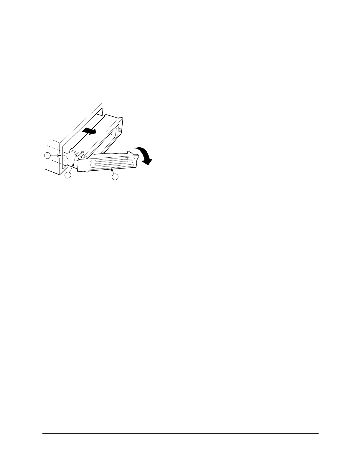
Customer Replaceable Unit (CRU) Procedures
1. Before removing the cover to work inside the system, observe the safety guidelines mentioned earlier.
2. Remove the bezel from the front of the chassis.
3. As shown in Figure 67, pull the retention lever (A) toward you until the tab end (B) of the lever is free of the
housing slot (C).
4. Pull the HDD assembly forward and out of the drive bay.
Figure 67. Removing a HDD Assembly From a Bay
C
B
6. Remove the new HDD assembly (hard disk drive mounted on a carrier) from its wrapper and place it on an antistatic surface.
7. Install the new HDD assembly into the drive bay by inserting the tab end (B) of the retention lever (A) into the
housing slot (C) and gently closing the lever.
Note : Closing the lever should seat the HDD into the backplane connector. If the drive does not
✍
8. Reinstall a carrier and air baffle in any bays where you are not reinstalling a HDD assembly.
✍
insert or seat properly, do not force the lever. Instead, check again to make sure the tab of the
retention lever is properly inserted into the housing before closing the lever.
Note : The Comprehensive Test should be run after changing any FRU, CRU, or adding an
optional component. See “Run System Diagnostic Test” on page 4-15.
A
OM11690
User Guide—Sun Cobalt LX50 Server 5-9
Page 94
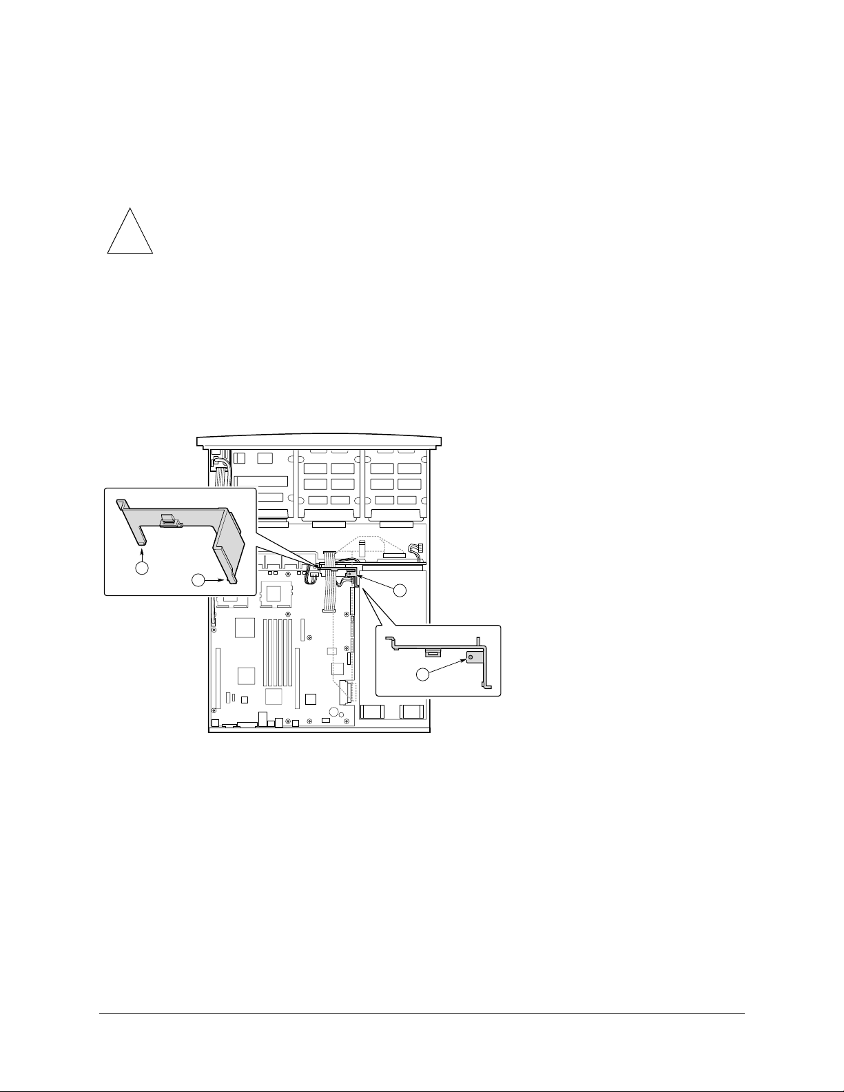
Chapter 5: Maintaining the Server
Air Baffle
The air baffle must be removed before you can replace the fan module.
Removal
Caution : Before touching or replacing any component inside the LX50 server, disconnect all
external cables and follow the instructions in “Safety: Before You Remove the Cover” on
!
1. Before removing the cover to work inside the system, observe the safety guidelines mentioned earlier.
2. Remove the chassis cover.
3. As shown in Figure 68, gently spread the air baffle walls at (B) and (C) and lift up until pin (A) is free of the
board mounting hole.
4. Remove the baffle from the chassis.
Figure 68. Removing the Air Baffle
page 5-2 and “Removing and Replacing the Cover” on page 5-3. Always place the server on a
grounded ESD pad and wear a properly grounded antistatic wrist strap.
B
C
A
A
OM11704
Installation
1. Ensure the flex cable, auxiliary power cable, and SCSI cables are routed under where you will be installing the
air baffle.
2. Aligning pin (A) with the board mounting hole, position the air baffle over the white server board power
connector.
3. Lower the baffle into position and press it down against the chassis floor.
4. Ensure tabs (B) and (C) are under the edge of the server board.
5-10 User Guide—Sun Cobalt LX50 Server
Page 95

Customer Replaceable Unit (CRU) Procedures
Fan Module
Caution : Before touching or replacing any component inside the LX50 server, disconnect all
external cables and follow the instructions in “Safety: Before You Remove the Cover” on
!
The fan module is a single component. The individual fans that make up the module are not swappable. Should a fan
fail, the entire module will need to be replaced. A tab on the side of the fan module makes replacement of the module
tool-less and very simple. The fan module is not hot swappable. The server must be turned off before the fan module
can be replaced.
To replace the fan module, refer to Figure 69 and follow these steps:
1. Before removing the cover to work inside the system, observe the safety guidelines previously given.
2. Remove the cover from the chassis.
3. Remove the air baffle.
4. Unplug the fan cable from the server board (D).
5. At the left end of the module, press on tab (B) to release it from the chassis slot (C).
page 5-2 and “Removing and Replacing the Cover” on page 5-3. Always place the server on a
grounded ESD pad and wear a properly grounded antistatic wrist strap.
6. Lift the module from the chassis. When the right end is free, detach the USB cable.
7. Attach the USB cable to the replacement module.
Caution : Failure to properly route the USB cable can cause it to interfere with the top cover. If
the cable is removed and then not placed properly under the cable clamp at the front, it may
!
8. Slide the “L” shaped foot on the right end of the module under the chassis tab near the chassis sidewall.
9. Lower the module to the chassis floor. Ensure it is situated between the raised guides, not on top of them.
10. Press down on the left end of the module until tab (B) fits into the chassis slot (C).
11. Plug the power cable into the system fan connector on the server board.
12. Install the air baffle.
✍
13. Replace the chassis cover.
✍
result in the cover crushing the USB cable and destroying the intrusion sensor on the front
panel board.
Note : Check to ensure that all cables are firmly seated and properly routed. Pay special care to
the flexible cable between the Main Board and backplane.
Note: The Comprehensive Test should be run after changing any FRU, CRU, or adding an
optional component. See “Run System Diagnostic Test” on page 4-15.
User Guide—Sun Cobalt LX50 Server 5-11
Page 96

Chapter 5: Maintaining the Server
Figure 69. Fan Module Replacement
B
C
D
A
OM11681A
5-12 User Guide—Sun Cobalt LX50 Server
Page 97

PCI Cards
Caution: Before touching or replacing any component inside the LX50 server, disconnect all
external cables and follow the instructions in “Safety: Before You Remove the Cover” on
!
page 5-2 and “Removing and Replacing the Cover” on page 5-3. Always place the server on a
grounded ESD pad and wear a properly grounded antistatic wrist strap.
Note: Add-in cards must be replaced while the riser card is removed from the chassis.
Customer Replaceable Unit (CRU) Procedures
✍
To replace a PCI card, follow these steps:
1. Before removing the cover to work inside the system, observe the previously stated safety guidelines.
2. Remove the chassis cover.
3. As shown in Figure 70, insert your finger in the plastic loop (A).
Figure 70. Removing a Riser Card
The server supports 3 V only and Universal PCI cards. It does not support 5 V only cards.
C
B
A
OM11692
4. Pull straight up and remove the riser card assembly from the chassis.
5. Open the retainer clip (B) on the riser card retention bracket.
6. Pull the PCI card out of the riser card slot (C).
7. Install the new PCI add-in card on the riser.
User Guide—Sun Cobalt LX50 Server 5-13
Page 98

Chapter 5: Maintaining the Server
8. Insert the riser card connector in the server board slot while aligning the tabs on the rear retention bracket with
the holes in the chassis.
Caution: Press the riser card straight down into the slot. Tipping it in the slot while installing it
may damage the riser card or board slot.
!
9. Firmly press the riser card straight down until it is seated in the server board slot.
10. Replace the chassis cover if you have no additional work to do inside the chassis.
Note: The Comprehensive Test should be run after changing any FRU, CRU, or adding an
✍
Battery
✍
optional component. See “Run System Diagnostic Test” on page 4-15.
Caution: Before touching or replacing any component inside the LX50 server, disconnect all
external cables and follow the instructions in “Safety: Before You Remove the Cover” on
page 5-2 and “Removing and Replacing the Cover” on page 5-3. Always place the server on a
grounded ESD pad and wear a properly grounded antistatic wrist strap.
The lithium battery on the server board powers the real time clock (RTC) for up to 10 years in the absence of power.
A low battery condition is stored in the System Event Log (SEL).
When the battery starts to weaken, it loses voltage, and the server settings stored in CMOS RAM in the RTC (for
example, the date and time) may be wrong. Contact your customer service representative or dealer for a list of
approved replacement batteries.
Warning: There is a danger of explosion if the battery is incorrectly replaced. Replace only
with the same or equivalent type recommended by the equipment manufacturer. Discard used
batteries according to the manufacturer’s instructions.
Note: The Comprehensive Test should be run after changing any FRU, CRU, or adding an
✍
optional component. See “Run System Diagnostic Test” on page 4-15.
5-14 User Guide—Sun Cobalt LX50 Server
Page 99
Field Replaceable Unit (FRU) Procedures
Field Replaceable Unit (FRU) Procedures
Replacing a CPU and Heatsink
Caution: The procedure below is for the attention of qualified service engineers only. Before
touching or replacing any component inside the LX50 server, disconnect all external cables
!
Safety Cautions
!
and follow the instructions in “Safety: Before You Remove the Cover” on page 5-2 and
“Removing and Replacing the Cover” on page 5-3. Always place the server on a grounded
ESD pad and wear a properly grounded antistatic wrist strap.
The server is certified to function properly only with Sun CPUs. Do not mix CPU steppings
and speeds or processor family types.
Caution: Pressing the power button does not turn off power to this board. Disconnect the
server board from its power source and from any telecommunications links, networks, or
modems before doing any of the procedures described in this guide. Failure to do this can
result in personal injury or equipment damage. Some circuitry on the server board may
continue to operate even though the front panel power button is off.
Electrostatic discharge (ESD) can damage server board components. Perform CPU replacement procedures only at an
ESD workstation. If no such station is available, you can provide some ESD protection by wearing an antistatic wrist
strap and attaching it to a metal part of the computer chassis.
Caution: CPU replacement must be performed by trained service personnel only! An ESD
wrist strap must be used for this procedure
!
User Guide—Sun Cobalt LX50 Server 5-15
Page 100
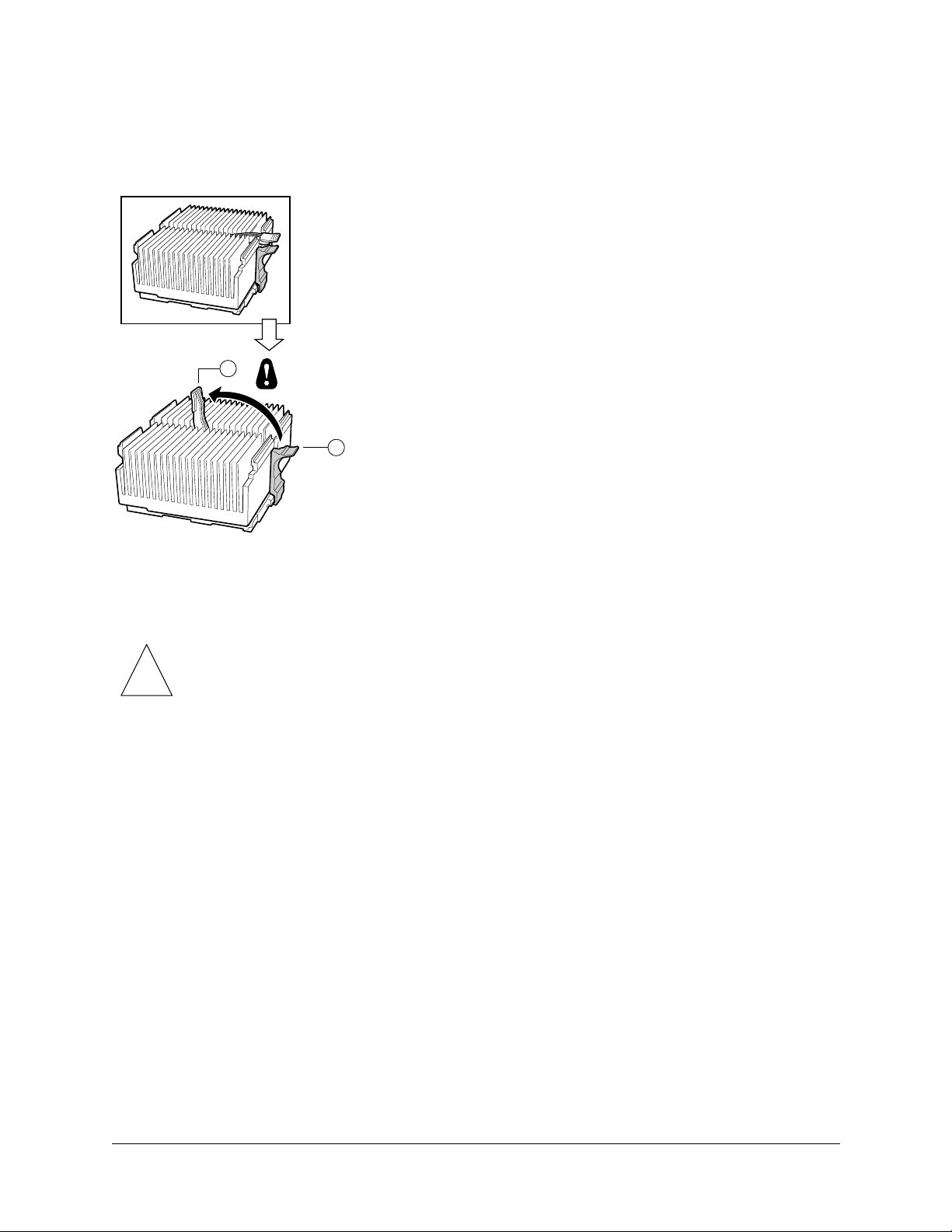
Chapter 5: Maintaining the Server
To replace a processor, follow these steps:
1. As shown in Figure 71, raise the green heatsink clamping locking lever (A) to the upper position.
Figure 71. Raising the Locking Lever
A
B
OM11709B
2. While depressing the black lift tab (B), press the side of the clamp opposite the lift tab towards the heatsink, then
carefully lift the clamp upwards at the lift point. Once one side is unclamped, the other side can be freed by
rotating the clamp bracket upwards.
Caution: Do not force the clamps free using any type of tool, as this is highly likely to cause
irreparable damage to the processor socket. The clamps will easily disengage once the correct
!
3. Gently lift the heatsink and the clamp.
✍
4. Grasp the end of the zero insertion force arm and bend it out slightly until it disengages from the socket tab.
5. Raise the zero insertion force arm on the processor socket (see Figure 72), making sure the arm is in the full
upright position.
procedure is followed.
Note: Do not separate the heatsink from the clamp and do not set the heatsink down on its
bottom side, as this may contaminate the thermal insulating material.
5-16 User Guide—Sun Cobalt LX50 Server
 Loading...