

Page 1

Sun Blade X6275 M2 Server Module Installation Guide
Part No: 821–1089
March 2012, Rev A, 7010774
Page 2

Copyright © 2010, 2011, 2012, Oracle and/or its aliates. All rights reserved.
This software and related documentation are provided under a license agreement containing restrictions on use and disclosure and are protected by intellectual
property laws. Except as expressly permitted in your license agreement or allowed by law, you may not use, copy, reproduce, translate, broadcast, modify, license,
transmit, distribute, exhibit, perform, publish or display any part, in any form, or by any means. Reverse engineering, disassembly, or decompilation of this software,
unless required by law for interoperability, is prohibited.
The information contained herein is subject to change without notice and is not warranted to be error-free. If you nd any errors, please report them to us in writing.
If this is software or related documentation that is delivered to the U.S. Government or anyone licensing it on behalf of the U.S. Government, the following notice is
applicable:
U.S. GOVERNMENT RIGHTS. Programs, software, databases, and related documentation and technical data delivered to U.S. Government customers are
"commercial computer software" or "commercial technical data" pursuant to the applicable FederalAcquisitionRegulation and agency-specic supplemental
regulations. As such, the use, duplication, disclosure, modication, and adaptation shall be subject to the restrictions and license terms set forth in the applicable
Government contract, and, to the extent applicable by the terms of the Government contract, the additional rights set forth in FAR 52.227-19, Commercial
Computer Software License (December 2007). Oracle America, Inc., 500 Oracle Parkway, Redwood City, CA 94065.
This software or hardware is developed for general use in a variety of information management applications. It is not developed or intended for use in any inherently
dangerous applications, including applications that may create a risk of personal injury. If you use this software or hardware in dangerous applications, then you shall
be responsible to take all appropriate fail-safe, backup, redundancy, and other measures to ensure its safe use. Oracle Corporation and its aliates disclaim any
liability for any damages caused by use of this software or hardware in dangerous applications.
Oracle and Java are registered trademarks of Oracle and/or its aliates. Other names may be trademarks of their respective owners.
Intel and Intel Xeon are trademarks or registered trademarks of Intel Corporation. All SPARC trademarks are used under license and are trademarks or registered
trademarks of SPARC International, Inc. AMD, Opteron, the AMD logo, and the AMD Opteron logo are trademarks or registered trademarks of Advanced Micro
Devices. UNIX is a registered trademark of The Open Group.
This software or hardware and documentation may provide access to or information on content, products, and services from third parties. Oracle Corporation and
its aliates are not responsible for and expressly disclaim all warranties of any kind with respect to third-party content, products, and services. Oracle Corporation
and its aliates will not be responsible for any loss, costs, or damages incurred due to your access to or use of third-party content, products, or services.
Ce logiciel et la documentation qui l’accompagnesont protégés par les lois sur la propriété intellectuelle. Ils sont concédés sous licence et soumis à des restrictions
d’utilisation et de divulgation. Sauf disposition de votre contrat de licence ou de la loi, vous ne pouvez pas copier, reproduire, traduire, diuser, modier, breveter,
transmettre, distribuer, exposer, exécuter, publier ou acher le logiciel, même partiellement, sous quelque forme et par quelque procédé que ce soit. Par ailleurs, il est
interdit de procéder à toute ingénierie inverse du logiciel, de le désassembler ou de le décompiler, excepté à des ns d’interopérabilité avec des logiciels tiers ou tel que
prescrit par la loi.
Les informations fournies dans ce document sont susceptibles de modication sans préavis. Par ailleurs, Oracle Corporation ne garantit pas qu’elles soient exemptes
d’erreurs et vous invite, le cas échéant, à lui en faire part par écrit.
Si ce logiciel, ou la documentation qui l’accompagne,est concédé sous licence au Gouvernement des Etats-Unis, ou à toute entité qui délivre la licence de ce logiciel
ou l’utilise pour le compte du Gouvernement des Etats-Unis, la notice suivante s’applique:
U.S. GOVERNMENT RIGHTS. Programs, software, databases, and related documentation and technical data delivered to U.S. Government customers are
"commercial computer software" or "commercial technical data" pursuant to the applicable FederalAcquisitionRegulation and agency-specic supplemental
regulations. As such, the use, duplication, disclosure, modication, and adaptation shall be subject to the restrictions and license terms set forth in the applicable
Government contract, and, to the extent applicable by the terms of the Government contract, the additional rights set forth in FAR 52.227-19, Commercial
Computer Software License (December 2007). Oracle America, Inc., 500 Oracle Parkway, Redwood City, CA 94065.
Ce logiciel ou matériel a été développé pour un usage général dans le cadre d’applications de gestion des informations. Ce logiciel ou matériel n’est pas conçu ni n’est
destiné à être utilisé dans des applications à risque, notamment dans des applications pouvant causer des dommages corporels. Si vous utilisez ce logiciel ou matériel
dans le cadre d’applications dangereuses, il est de votre responsabilité de prendre toutes les mesures de secours, de sauvegarde, de redondance et autres mesures
nécessaires à son utilisation dans des conditions optimales de sécurité. Oracle Corporation et ses aliés déclinent toute responsabilité quant aux dommages causés
par l’utilisation de ce logiciel ou matériel pour ce type d’applications.
Oracle et Java sont des marques déposées d’OracleCorporation et/ou de ses aliés. Tout autre nom mentionné peut correspondre à des marques appartenant à
d’autrespropriétaires qu’Oracle.
Intel et Intel Xeon sont des marques ou des marques déposées d’Intel Corporation. Toutes les marques SPARC sont utilisées sous licence et sont des marques ou des
marques déposées de SPARC International, Inc. AMD, Opteron, le logo AMD et le logo AMD Opteron sont des marques ou des marques déposées d’Advanced Micro
Devices. UNIX est une marque déposée d’The Open Group.
Ce logiciel ou matériel et la documentation qui l’accompagne peuvent fournir des informations ou des liens donnant accès à des contenus, des produits et des services
émanant de tiers. Oracle Corporation et ses aliés déclinent toute responsabilité ou garantie expresse quant aux contenus, produits ou services émanant de tiers. En
aucun cas, Oracle Corporation et ses aliés ne sauraient être tenus pour responsables des pertes subies, des coûts occasionnés ou des dommages causés par l’accès à
des contenus, produits ou services tiers, ou à leur utilisation.
120323@25097
Page 3

Contents
Using This Documentation ...................................................................................................................5
Product Information Web Site ......................................................................................................5
Related Books ..................................................................................................................................5
About This Documentation (PDF and HTML) ..........................................................................7
Documentation Comments ...........................................................................................................8
Contributors ....................................................................................................................................8
Change History ...............................................................................................................................8
Overview of the Sun Blade X6275 M2 Server Module .......................................................................9
Commonly Used Terms .................................................................................................................9
Product Description .................................................................................................................... 10
Product Features .......................................................................................................................... 12
Specications ................................................................................................................................ 15
Server Module Front Panel and Indicators ............................................................................... 17
Installing and Powering On the Server Module ............................................................................... 19
About Your Server Module Shipment ....................................................................................... 19
Finding the Serial Number and Accessing Warranty Support Information ......................... 20
Adding Optional Components .................................................................................................. 21
Installation Prerequisites ............................................................................................................ 22
How to Install Your Server Module ........................................................................................... 23
How to Apply Full Power to a Server Module Node ................................................................. 25
How to Power O a Server Module Node ................................................................................. 26
Troubleshooting Server Power States ........................................................................................ 26
Setting Up ILOM ................................................................................................................................. 29
CMM and Node ILOM Overview .............................................................................................. 30
Obtaining the ILOM IP Address ................................................................................................ 33
Accessing ILOM ........................................................................................................................... 38
Conguring an ILOM IP Address .............................................................................................. 41
Accessing the Host Console Through ILOM ............................................................................ 43
3
Page 4

Contents
Installing a Supported OS ................................................................................................................... 49
Flash Modules ............................................................................................................................... 50
USB Flash Drive ........................................................................................................................... 50
Specifying a Boot Device ............................................................................................................. 51
Index ......................................................................................................................................................53
Sun Blade X6275 M2 ServerModule Installation Guide • March 2012, Rev A, 70107744
Page 5

UsingThis Documentation
This section describes related documentation, submitting feedback, and a document change
history.
■
“Product Information Web Site” on page 5
■
“Related Books” on page 5
■
“About This Documentation (PDF and HTML)” on page 7
■
“Documentation Comments” on page 8
■
“Contributors” on page 8
■
“Change History” on page 8
Product Information Web Site
For information about the Sun Blade X6275 M2 server module, go to the
http://www.oracle.com/goto/blades page and click on your server model listed near the
bottom.
At that site, you can nd links to the following information and downloads:
■
Product information and specications
■
Software and rmware downloads
Related Books
The following is a list of documents related to Oracle's Sun Blade X6275 M2 server module.
These and additional support documents are available on the web at:
http://download.oracle.com/docs/cd/E19962-01/
5
Page 6
Related Books
Document Group Document Description
Sun Blade X6275 M2 Server
Module Documentation
Sun Blade X6275 M2 Server
Module Product Documentation
Sun Blade X6275 M2 Server Module
Getting Started Guide
Sun Blade X6275 M2 Server Module
Installation Guide *
Sun Blade X6275 M2 Server Module
Product Notes *
Sun Blade X6275 M2 Server Module
Installation Guide for Oracle Solaris
Operating Systems *
Sun Blade X6275 M2 Server Module
Installation Guide for Linux
Operating Systems *
Sun Blade X6275 M2 Server Module
Installation Guide for Windows
Operating Systems *
Sun Blade X6275 M2 Server Module
Installation Guide for Oracle VM
Operating Systems *
Oracle x86 Servers Diagnostics
Guide *
Integrated HTML version of all
starred (*) documents, including
Search and Index.
Pictorial setup quick reference.
How to install, rack, and congure
the server up to initial power-on.
Important late-breaking
information about your server.
How to install the Oracle Solaris OS
on your server.
How to install a supported Linux
OS on your server.
How to install a supported version
of Microsoft Windows OS on your
server.
How to install a supported version
of Oracle VM OS on your server.
How to diagnose problems with
your server.
Sun Disk Management
Documentation
x64 Servers Applications and
Utilities Documentation
Sun Blade X6275 M2 ServerModule Installation Guide • March 2012, Rev A, 70107746
Sun Blade X6275 M2 Server Module
Service Manual *
Sun Blade X6275 M2 Server Module
Safety and Compliance Guide
Oracle Integrated Lights Out
Manager (ILOM) 3.0 Supplement
for the Sun Blade X6275 M2 Server
Module *
Sun x64 Server Disk Management
Overview
Sun x64 Server Utilities Reference
Manual
How to service and maintain your
server.
Safety and compliance information
about your server.
Version-specic supplemental
information for your server’s
Integrated Lights Out Manager.
Information about managing your
server’s storage.
How to use the available utilities
included with your server.
Page 7

About This Documentation (PDF and HTML)
Document Group Document Description
Oracle Integrated Lights Out
Manager (ILOM) 3.0
Documentation
Oracle Integrated Lights Out
Manager (ILOM) 3.0 Feature
Updates and Release Notes
Oracle Integrated Lights Out
Manager (ILOM) 3.0 Getting
Started Guide
Oracle Integrated Lights Out
Manager (ILOM) 3.0 Concepts
Guide
Oracle Integrated Lights Out
Manager (ILOM) 3.0 Web Interface
Procedures Guide
Oracle Integrated Lights Out
Manager (ILOM) 3.0 CLI
Procedures Guide
Oracle Integrated Lights Out
Manager (ILOM) 3.0 Management
Protocols Reference Guide
Information about new ILOM
features.
Overview of ILOM 3.0.
Conceptual information about
ILOM 3.0.
How to use ILOM through the web
interface.
How to use ILOM through
commands.
Information about management
protocols.
Translated versions of some of these documents are available at the web site described
previously in Simplied Chinese, Korean, Japanese, French and Spanish. English
documentation is revised more frequently and might be more up-to-date than the translated
documentation.
About This Documentation (PDF and HTML)
This documentation set is available in both PDF and HTML. The information is presented in
topic-based format (similar to online help) and therefore does not include chapters,
appendixes, or section numbering.
A PDF that includes all information on a particular topic subject (such as hardware installation
or product notes) can be generated by clicking on the PDF button in the upper left corner of the
page.
Note – The “Documentation Information” and “Index” topics do not have associated PDF.
7
Page 8

Documentation Comments
Documentation Comments
Oracle is interested in improving the product documentation and welcomes your comments
and suggestions. You can submit comments at:
Contributors
Primary Authors: Ralph Woodley, Michael Bechler, Ray Angelo, Mark McGothigan.
Contributors: Kenny Tung, Adam Ru, Isaac Yang, Stone Zhang, Susie Fang, Lyle Yang, Joan
Xiong, Redarmy Fan, Barry Xiao, Evan Xuan, Neil Gu, Leigh Chen, Eric Kong, Kenus Lee.
Change History
The following lists the release history of this documentation set:
■
November 2010. Initial publication.
■
November 2010. Information added to the Sun Blade X6275 M2 Server Module Product
Notes for platform software release 1.1. Added new rmware version, PC-Check 6.27s
support, CRs 6994690, 6992284, 6994464.
■
January 2011. Information added to the Sun Blade X6275 M2 Installation Guide for
conguring pre-installed Oracle Solaris or Oracle VM. Information added to the Sun Blade
X6275 M2 Server Module Product Notes for platform software release 1.2. Added new
rmware version, CRs 6971164, 7009654, 7009666, 7010601. Information added to the
Oracle Integrated Lights Out Manager (ILOM) 3.0 Supplement for the Sun Blade X6275 M2
Server Module for proving physical presence, reading available_power in ILOM.
■
March 2011. Information removed from the Sun Blade X6275 M2 Installation Guide for
conguring pre-installed Oracle Solaris OS or Oracle VM on FMod. Information removed
from the Sun Blade X6275 M2 Product Notes on available pre-installed Oracle Solaris OS or
Oracle VM on FMod.
■
September 2011. Information added to the Sun Blade X6275 M2 Server Module Product
Notes for platform software release 1.3, including new rmware version and new OS version
support. Added information about BIOS hardware prefetch options to the Sun Blade X6275
M2 Server Module Product Notes and the Sun Blade X6275 M2 Server Module Service
Manual. Fixed CRs 6971164 and 7009654.
■
January 2012. Updated physical dimension specications in the Sun Blade X6275 M2 Server
Module Installation Guide and the Sun Blade X6275 M2 Server Module Service Manual.
Added information to the Sun Blade X6275 M2 Server Module Product Notes for OS support
for Oracle VM 3.0.1 (1GbE), 3.0.2 (1GbE) and 3.0.3 (10GbE).
■
March 2012. Information corrected in the Sun Blade X6275 M2 Installation Guide for the
number of 10 GbE ports per node. Information added to the Sun Blade X6275 M2 Product
Notes for CR 7072665.
http://www.oracle.com/goto/docfeedback.
Sun Blade X6275 M2 ServerModule Installation Guide • March 2012, Rev A, 70107748
Page 9

Overview of the Sun Blade X6275 M2 Server Module
This section provides an overview of the features of Oracle's Sun Blade X6275 M2 server
module including product specications.
■
“Commonly Used Terms” on page 9
■
“Product Description” on page 10
■
“Product Features” on page 12
■
“Specications” on page 15
■
“Server Module Front Panel and Indicators” on page 17
Commonly Used Terms
The following table identies some of the terms commonly used in this guide.
Term Denition
Chassis Sun Blade 6000 modular system hardware.
For additional information about the Sun Blade 6000 modular system, go to
http://download.oracle.com/docs/cd/E19938-01/index.html.
CMM Chassis Monitoring Module. A baseboard management controller (BMC) for the
entire Sun modular system chassis.
FMod Flash Module. A user-installable high performance solid-state storage device
(similar to a DIMM) that acts like a SATA disk and uses ash memory technology for
increased data access speeds.
ILOM Oracle'sIntegrated Lights Out Manager (ILOM) is the embedded management
software that runs on the server module node SP and CMM that enables you to
manage your system.
For additional information about ILOM, refer to the Integrated Lights Out Manager
documentation.
NEM Network Express Module (NEM). A networking I/O component that plugs into a
Sun Blade Modular System chassis. The chassis contains two NEM slots: NEM 0 and
NEM 1.
9
Page 10

Product Description
Term Denition
Node An independent computer that resides on the server blade (also called compute
PCIe EM PCI Express (PCIe) ExpressModule (EM). PCIe EMs can be installed in the chassis to
Server module Sun Blade X6275 M2 server module hardware. The physical server blade that plugs
SP Embedded service processor (SP) on the server module. The SP is a "baseboard
Product Description
The Sun Blade X6275 M2 server module is a dual-node high-density computing blade for cloud,
middleware, and virtualized environments. The server blade's two compute nodes (Node 0 and
Node 1) are housed on a single motherboard in a single blade enclosure. The server module is
only supported in the Sun Blade 6000 modular system chassis.
node). Each node has its own CPU, memory, I/O, and service processor. The Sun
Blade X6275 M2 server module has two nodes—two separate servers on one blade.
provide installed server blades option card expansion. Each node of the Sun Blade
X6275 M2 server module has one available PCIe EM chassis slot.
Note – For the server module, node 0 is assigned to chassis blade PCIe EM slot 1, and
node 1 is assigned to chassis blade PCIe EM slot 0.
into a Sun Blade 6000 modular system chassis.
management controller" (BMC). Each node of the server blade has its own dedicated
SP. The Sun Blade 6000 modular system chassis also has its own SP called the chassis
monitoring module (CMM).
The server is available in two models:
■
The Sun Blade X6275 M2 server module with GbE (X6275M2–BB).
■
The Sun Blade X6275 M2 server module with 10GbE (X6275M2–CB).
The following illustration shows the layout of the main system components:
Sun Blade X6275 M2 ServerModule Installation Guide • March 2012, Rev A, 701077410
Page 11
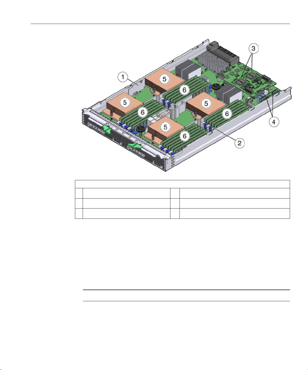
Figure Legend
Product Description
1 Node 0 2 Node 1
3 AST2100 service processors (one per node) 4 Flashmodules (one per node)
5 CPUs (two per node) 6 Memory DIMMs (12 per node)
The server module is congured as follows:
■
Both server module compute nodes are identical and symmetric, but are fully independent
of each other. Each node supports two CPUs and 12 cores of compute density.
■
Each node is based on a two-socket six-core Intel Xeon 5600 series platform that includes
the Intel 5500 chipset (IOH–24D Northbridge and ICH10 Southbridge) and network I/O.
■
Each node supports up to twelve low voltage DDR3 DIMMs (up to 96 GB of main memory
using 8 GB DIMMs).
Note – Both nodes of the server module must be congured identically (CPUs and memory).
■
The following network interfaces are available:
■
One 10/100/1000Base-T Ethernet port per node using the embedded Intel 82567 GbE
controller (server module model X6275M2–BB).
11
Page 12

Product Features
—Or—
■
One 10GbE ports per node using the embedded Mellanox ConnectX–2 controller and
XAUI (server module model X6275M2–CB).
Note – The 10GbE signal for this model is generated by the embedded Mellanox
ConnectX-2 controller, and therefore no Fabric Expansion Modules (FEM) are required.
The only 10GbE NEM currently supported for this model is the Sun Blade 6000 Ethernet
Switched 24p 10GbE NEM (X2073A).
■
Each node has its own service processor based on the AST2100 chip providing Oracle
Integrated Lights Out Management (ILOM version 3.0), and a shared 10/100 Ethernet
management port.
■
Each node supports the addition of an optional 24 GB Sun Flash Module (FMod), which
provides fast and reliable solid-state storage and a secure local boot source for the node.
Note – Server module nodes do not support the installation of a RAID Expansion Module
(REM). However, each node has one chassis PCIe EM slot available which could be used for
a supported external host bus adapter (HBA) connected to external storage.
■
Each node has an internal USB port (under the service processor board at the back of the
blade) for the addition of an optional USB ash drive for local storage.
See Also
■
“Commonly Used Terms” on page 9
■
“Product Features” on page 12
■
“Specications” on page 15
■
“Server Module Front Panel and Indicators” on page 17
Product Features
Feature Description
Chassis compatibility Sun Blade 6000 modular system with PCIe 2.0 midplane (standard with model
Sun Blade X6275 M2 ServerModule Installation Guide • March 2012, Rev A, 701077412
A90–B).
The minimum CMM ILOM rmware required is 3.0.10.15, included in chassis
software release 3.2.
Page 13

Product Features
Feature Description
Chassis midplane I/O Depending on your server model, each node supports either a 1GbE or 10GbE
interface through the chassis midplane to the NEM.
Note – Although a supported NEM might include both 1GbE and 10GbE ports,
the server module only supports one interface type.
■
One (x8) PCIe 2.0 bus connection per node to a chassis PCIe EM slot. Node
0 is assigned to chassis blade PCIe EM slot 1, node 1 is assigned to chassis
blade PCIe EM slot 0.
■
One 10/100/1000Base-T Ethernet port per node with the 1GbE model
(X6275M2–BB). The port for node 0 is assigned to a supported NEM in
chassis slot NEM0, the port for node 1 is assigned to an supported NEM in
chassis slot NEM1.
■
One 10GbE port per node with the 10GbE model (X6275M2–CB). The
port for node 0 is assigned to a supported NEM in chassis slot NEM0, the
port for node 1 is assigned to an supported NEM in chassis slot NEM1.
CPU Up to four Intel Xeon Processor E5600 Series six-core processors per server
module (two per node). Twelve cores per node, for a total of twenty–four cores
per server module.
Note – Both nodes of the server module must be congured identically (CPUs
and memory).
Dual-node design Two independent, symmetric compute nodes, 0 and 1, in a single blade
enclosure.
Front panel I/O Two Universal Connector Ports (UCP), one per node, are available for use with
the multi-port (dongle) cable. The multi-port cable provides the following
interface connections:
■
VGA graphics port.
■
RJ-45 serial management port.
■
Dual USB ports (keyboard/mouse/USB drive).
Memory
■
Twenty-four memory slots total (12 slots per compute node). Slots support
up to 1333 MHz low voltage DDR3, ECC registered, DIMMs.
■
Up to 96 GB of main memory per node using 8 GB DIMMs.
■
Up to 48 GB of main memory per node using 4 GB DIMMs.
■
Up to 2 DDR3 DIMMs per channel, 3 channels per installed processor.
Note – Both nodes of the server module must be congured identically (CPUs
and memory).
13
Page 14

Product Features
Feature Description
Network Express Module
(NEM) compatibility
Each node host requires a NEM for network I/O (for more on NEM
requirements see
“Installation Prerequisites” on page 22). NEM SAS ports
(internal or external) are not supported.
The following NEMs are supported for the Sun Blade X6275 M2 with 1GbE
(X6275M2–BB):
■
Sun Blade 6000 10p GbE Pass-Thru NEM (X4250A) — recommended.
■
Sun Blade 6000 Virtualized Multi-Fabric 10GbE M2 NEM (X4338A).
■
Sun Blade 6000 Virtualized Multi-Fabric 10GbE NEM (X4238).
■
Sun Blade 6000 Multi-Fabric NEM (X4212A).
The following NEM is supported for the Sun Blade X6275 M2 with 10GbE
(X6275M2–CB):
■
Sun Blade 6000 Ethernet Switched 24p 10GbE NEM (X2073A) — no FEMs
are required for the Sun Blade X6275 M2 server module.
Note – For the 10GbE model, the Sun Blade 6000 Ethernet Switched 24p 10GbE
NEM does not provide a 1GbE interface and therefore the 1GbE interface,
although present on each server node, is disabled by rmware.
Operating systems Operating systems such as Oracle Solaris, Linux, Windows and Oracle VM are
supported. For a complete list of supported OS versions for your server, refer to
“Supported Operating Systems” in Sun Blade X6275 M2 Server Module
the
Product Notes
.
Service Processor (SP) Each node includes an AST2100 service processor (SP). The SP provides IPMI
2.0 compliant remote management capabilities. Each node SP features:
■
Integrated Lights Out Manager (ILOM version 3.0).
■
Local ILOM command-line access using a serial connection.
■
10/100 management Ethernet port to midplane (shared by both node SPs).
■
Remote keyboard, video, mouse, and storage (KVMS) over IP.
Storage
■
Two internal slots for optional 24 GB SATASun Flash Modules (one per
node).
■
Two internal ports for an optional USB 2.0 ash drive (one per node).
Note – Server module nodes do not support the installation of a RAID
Expansion Module (REM) and therefore do not support internal chassis SAS
connections to blade storage. However, each node has an assigned PCIe EM
slot that could be used for an HBA connecting to external storage.
Video A maximum resolution of 1280x1024 is supported with 8 MB of video
memory.
See Also
■
“Commonly Used Terms” on page 9
■
“Product Description” on page 10
Sun Blade X6275 M2 ServerModule Installation Guide • March 2012, Rev A, 701077414
Page 15

■
“Specications” on page 15
■
“Server Module Front Panel and Indicators” on page 17
Specications
The following tables provide information on server module dimensions, electrical and
environmental specications.
Server module dimensions:
Specication Value
Height 12.9 inches/327.2 mm
Width 1.8 inches/44.5 mm
Depth 20.1 inches/511.7 mm
Weight Maximum: 20.6 lbs (9.4 kg), with twenty–four 4GB
Electrical specications:
Specications
low voltage DDR3 DIMMs and four Intel Xeon EP
processors installed
Specication Value
Voltage (nominal) 12V main from chassis backplane
3.3V AUX from chassis backplane
Power (maximum) 604W (maximum operational) - with twenty-four 4
GB low voltage DDR3 DIMMs and four Intel Xeon EP
processors installed
Environmental specications:
Specication Value
Temperature (operating) 41 to 90° F
5 to 32° C
Temperature (storage) -40 to 158° F
-40 to 70° C
Humidity 10 to 90% non-condensing
15
Page 16
Specications
Specication Value
Operating altitude 0 to 10,000 feet (0 to 3048 meters)
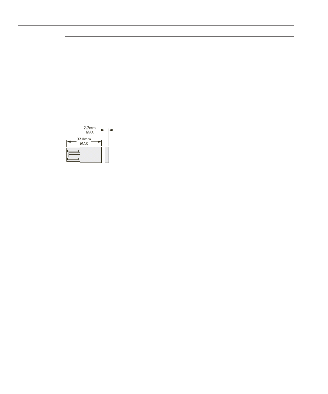
Internal USB port specication:
The server module has two internal USB ports, one per node. A USB ash drive with a standard
USB 2.0 interface can be obtained from third-party sources. The USB ash drive must be no
larger than 2.7 mm wide and 32.0 mm long, as shown below:
See Also
■
“Commonly Used Terms” on page 9
■
“Product Description” on page 10
■
“Product Features” on page 12
■
“Server Module Front Panel and Indicators” on page 17
Sun Blade X6275 M2 ServerModule Installation Guide • March 2012, Rev A, 701077416
Page 17
Server Module Front Panel and Indicators
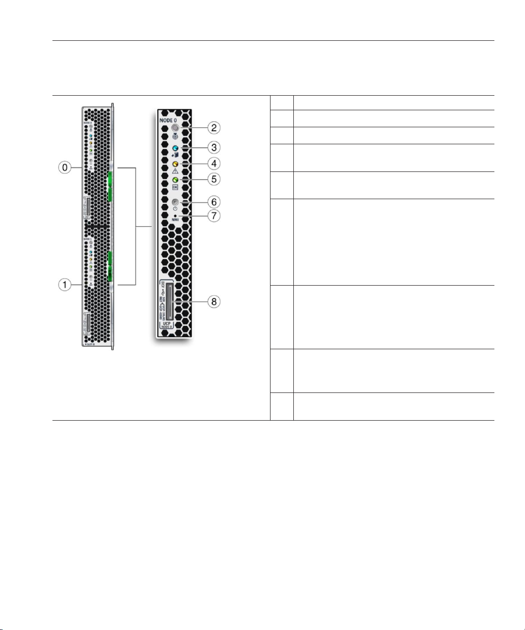
0 Node 0.
1 Node 1.
2 Locate LED (white). Press button to identify server.
3 Ready to Remove server module LED (blue). Main power
removed.
4 Service Action Required LED (amber). A fault condition
has occurred.
5 OK/Power LED (green). Modes:
■
SP booting—fast blink, 0.125 second on, 0.125 second
o.
■
Standby power—blink, 0.1 second on, 2.9 seconds o.
■
Host booting—slow blink, 0.5 second on, 0.5 second
o.
■
Full power—steady on.
6 Power button. Press briey to toggle the server between
standby and full power.
Caution – Pressing the Power button for more than 4 seconds
when in full power initiates immediate shutdown to
standby power. Can cause data loss.
Server Module Front Panel and Indicators
7 Non-Maskable Interrupt (NMI) button.
Caution – Service use only. Do not press unless instructed by
Oracle personnel.
8 Universal Connector Port (UCP) Used for multi–port
(dongle) cable.
17
Page 18

18
Page 19

Installing and Powering On the Server Module
This section describes how to install your server module into a Sun Blade 6000 modular system
chassis.
The installation consists of the following tasks:
Step Task Link
1 Unpack the server module from the shipping
container.
2 Find the server's serial number and learn where to
go to access warranty support information.
3 If applicable, install the optional server module
components before you install the server module
into the chassis.
4 Ensure that other pre-installation steps are
complete.
5 Install the server module into a powered-on
chassis.
6 Apply main power to your server module. “How to Apply Full Powerto a Server Module
About Your Server Module Shipment
Standard congurations for the server module are assembled at the factory and shipped ready
for installation in a Sun Blade 6000 series chassis.
Standard server components found in the packing carton include:
“About Your Server Module Shipment” on page 19
“Finding the Serial Number and Accessing
Warranty Support Information” on page 20
“Adding Optional Components” on page 21
“Installation Prerequisites” on page 22
“How to Install Your Server Module” on page 23
Node” on page 25
19
Page 20

Finding the Serial Number and Accessing Warranty Support Information
Figure
Number Description
1 Documentation
2 Server module
3 Box
4 Shipping label
See Also
■
“Finding the Serial Number and Accessing Warranty Support Information” on page 20
■
“Adding Optional Components” on page 21
■
“Installation Prerequisites” on page 22
■
“How to Install Your Server Module” on page 23
Finding the Serial Number and AccessingWarranty Support
Information
If you ever need Oracle warranty support for your server module, you must have your serial
number. The serial number is located on a label on the front ejector of the server module [see 2].
Another label, which requires server module removal, is on the top of the server module [see 1].
Sun Blade X6275 M2 ServerModule Installation Guide • March 2012, Rev A, 701077420
Page 21

Adding Optional Components
Note – The server module serial number can also be viewed from CMM ILOM. For more
information about using CMM ILOM, refer to
“CMM and Node ILOM Overview” on page 30.
To view support and warranty information for your product, go to: http://www.oracle.com/
us/support/index.html
See Also
■
“Adding Optional Components” on page 21
■
“Installation Prerequisites” on page 22
■
“How to Install Your Server Module” on page 23
Adding Optional Components
Optional server module components that you purchase independent of the standard
conguration are shipped separately and, in most cases, should be installed before you install
the server module into the chassis.
Note – Both nodes of the server module must be congured identically (CPUs and memory).
The following optional server module components can be ordered and purchased separately:
■
CPU assembly options
■
DDR3 DIMM memory kits
■
Flash Modules (FMods)
■
Multi–port (or dongle) cable
■
Software media
Supported components and their part numbers are subject to change over time and without
notice. For the most up-to-date list, go to:
.
https://support.oracle.com/handbook_private/
21
Page 22

Installation Prerequisites
Note – This site requires an Oracle web account to access.
Click the name and model of your server. On the product page that opens for the server, click
Full Components List for a list of components.
If you ordered any options that are eld-replaceable units (FRUs) or customer replaceable units
(CRUs), refer to the service label on the top cover or the
Procedures” in Sun Blade X6275 M2 Server Module Service Manual
Note – This server is fully compliant with the Reduction of Hazardous Substances (RoHS)
“Component Removal and Installation
for installation instructions.
Directive.
See Also
■
“Installation Prerequisites” on page 22
■
“How to Install Your Server Module” on page 23
Installation Prerequisites
Ensure the following tasks are complete before installing your server module into the Sun Blade
6000 modular system chassis.
1. Install any optional components for the server module. See
on page 21
2. Ensure that the Sun Blade 6000 modular system chassis in which you will install the server
module is running with supported hardware and rmware and has no faults:
■
■
■
■
Sun Blade X6275 M2 ServerModule Installation Guide • March 2012, Rev A, 701077422
.
Conrm that the chassis midplane supports PCIe 2.0 (standard with model A90–B).
Refer to the Sun Blade 6000 Modular System Product Notes for the latest information on
how to determine your midplane version.
The Chassis Monitoring Module (CMM) is at rmware version 3.0.10.15 (available with
Sun Blade 6000 modular system software release 3.2) or later.
All required power and data cables to the chassis are attached.
The Network Expansion Module(s) (NEMs) that are supported for use with your server
module have been installed in the chassis and are operating without faults. Refer to the
“Supported Hardware” in Sun Blade X6275 M2 Server Module Product Notes for more
information.
“Adding Optional Components”
Page 23

Installation Prerequisites
Note – For the Sun Blade X6275 M2 with 1GbE (X6275M2–BB), each node has one
network port: the port for node 0 is assigned to a supported NEM in chassis slot NEM0,
the port for node 1 is assigned to an supported NEM in chassis slot NEM1.
For the Sun Blade X6275 M2 with 10GbE (X6275M2–CB), each node has one network
port: the port for node 0 is assigned to a supported NEM in chassis slot NEM0, the port
for node 1 is assigned to an supported NEM in chassis slot NEM1.
For information about installing chassis components, attaching cables, and powering on the
chassis, refer to the Sun Blade 6000 modular system chassis documentation at:
http://download.oracle.com/docs/cd/E19938-01/index.html
3. Choose a method for connecting to each node's Integrated Lights Out Manager (ILOM)
service processor (SP). These could include the following:
■
A network connection. You need a PC or workstation connected to the same network as
the SP.
■
A direct node SP connection using the serial management port of an optional multi-port
cable connected to the node's UCP connector on the server's front panel (refer to the
“Using the Multi-Port Cable” in Sun Blade X6275 M2 Server Module Service Manual for
details). You need a PC with terminal emulation software or ASCII terminal
workstation. A terminal server can also be used.
4. Choose a method for connecting to the host console (BIOS and OS). These could include
the following:
■
A network connection to the SP so that you can use ILOM to remotely redirect the host
console. You need a PC or workstation connected to the same network as the SP.
■
A direct host connection through the multi-port cable connector (VGA and USB). Refer
to the
“Using the Multi-Port Cable” in Sun Blade X6275 M2 Server Module Service
Manual
for details.
Next Steps
■
“How to Install Your Server Module” on page 23
■
“Setting Up ILOM” on page 29
■
“Installing a Supported OS” on page 49
▼
How to Install Your Server Module
Perform all steps and fulll all requirements in “Installation Prerequisites” on page 22.BeforeYou Begin
23
Page 24

Installation Prerequisites
1
2
3
4
Verify that the Sun Blade 6000 modular system chassis is powered-on and operating normally
(without faults).
When the chassis is powered-on, the fans are operating and the chassis OK/Power LED
illuminates a steady-on green light. The OK/Power LEDs are located on both the front and back
of the chassis. If the chassis is not powered on, or in a fault state, refer to your chassis
documentation for information on how to remedy the issue.
Locate a free blade slot in the chassis and remove slot ller panel.
Pinch together the ends of the ejector arm handle to unlock it, rotate the lever out to the open
position, and eject the ller panel.
Keep the ller panel for later use.
Caution – If you are not installing a server module into a slot, do not remove the slot ller panel.
The slot ller panel is required to meet FCC standards for electromagnetic interference (EMI).
Do not operate the chassis with empty slots for more than 60 seconds. Always insert a ller
panel into an empty slot to reduce the possibility of chassis shutdown.
Open both of the server module ejectorlevers and position the servermodule vertically so that
the ejectors are on the right.
Install the server as follows:
a. Push the server module into the slot until the server module stops and is ush with the
chassis [see 1].
b. Lock the server module into the chassis.Rotate the top ejector down while rotating the
bottom ejector up until they both latch into place [see 2].
The server module is now locked in the chassis.
Verify that the server module's LEDs illuminate properly.
5
After installing a server module into a powered-on chassis, each server module node SP
automatically boots using standby power from the chassis power supplies. At this point, the
chassis OK/Power LED should be steady-on green. The server module front panel indicators
illuminate as follows:
Sun Blade X6275 M2 ServerModule Installation Guide • March 2012, Rev A, 701077424
Page 25

Next Steps
Installation Prerequisites
■
After you plug in the server module, all four server module LEDs (on each node) blink three
times. This indicates that the blade has been powered on and the SP boot process has begun.
■
The green OK/Power LEDs on each node blinks rapidly. This indicates that the node SP is
booting (0.125 seconds on, 0.125 seconds o).
■
After each node SP completes its boot cycle, the green OK/Power LEDs on each node blinks
briey once every 3 seconds indicating that the node is in standby power mode.
Tip – For front panel LED information, see to the “Server Module Front Panel and Indicators” on
. For additional information about server module indicators, server module removal,
page 17
power procedures, and front panel cable connections, refer to the
Components Overview” in Sun Blade X6275 M2 Server Module Service Manual
Both server nodes should be in the standby power state.
6
■
“How to Apply Full Power to a Server Module Node” on page 25
■
“How to Power O a Server Module Node” on page 26
■
“Troubleshooting Server Power States” on page 26
■
“Setting Up ILOM” on page 29
■
“Installing a Supported OS” on page 49
“Server Module and
.
▼
How to Apply Full Power to a Server Module Node
■
Each node is powered on separately.
■
The method described here requires you to be physically at the server. Alternatively, you can
log into each node’s ILOM and power-on the node remotely.
Verify that the OK/PowerLED on the front panel of the server module is in a standby blink state.
1
The green OK/Power LEDs on each node blinks briey once every 3 seconds indicating that the
node is in standby power mode. See
Press and release the recessed Power button on the server module front panel for the node to be
2
“Server Module Front Panel and Indicators” on page 17.
powered on.
During power-on, you will see the server module front panel indicators illuminate as follows:
■
The node's green OK/Power LED slowly blinks. This indicates that the node is booting (0.5
seconds on, 0.5 seconds o).
■
The node's green OK/Power LED illuminates a steady-on green light. This indicates that the
boot cycle is complete and the node is ready.
The front panel OK/Power LED for a server module node illuminates a steady-on green to
3
indicate that the node has successfully powered on.
25
Page 26

TroubleshootingServer PowerStates
Repeat Steps 1 through 3 to power on the second node.
4
See Also
■
“How to Power O a Server Module Node” on page 26
■
“Troubleshooting Server Power States” on page 26
■
“Setting Up ILOM” on page 29
■
“Installing a Supported OS” on page 49
▼
How to Power O a Server Module Node
■
Each node is powered o separately.
■
The method described here requires you to be physically at the server. Alternatively, you can
log into each node’s ILOM and remotely power-o the node.
To power o the servermodule node from full power mode, use one of the followingtwo
●
methods:
■
Graceful shutdown. Press and release the Powerbutton on the front panel.
This operation will cause any Advanced Conguration and Power Interface (ACPI) enabled
operating system to perform an orderly shutdown of the node operating system. Servers not
running ACPI-enabled operating systems will shut down to standby power mode
immediately.
■
Immediate shutdown. Press and hold the Powerbutton for veseconds to forcepower o
and to enter standby power mode.
■
See Also
“How to Apply Full Power to a Server Module Node” on page 25
■
“Troubleshooting Server Power States” on page 26
■
“Setting Up ILOM” on page 29
■
“Installing a Supported OS” on page 49
Troubleshooting Server Power States
Each time a server module powers on in a Sun Blade 6000 modular system, it queries the CMM
to ensure that there is enough power available from the power supply units (PSUs) to power on
the server. If there is not enough power to power on the server module, the CMM denies the
server module from receiving power (both standby and main). If this situation occurs, the
OK/Power LED on the front panel of the server module will remain o. To troubleshoot this
power issue, follow these guidelines:
■
Review the ILOM event log messages to determine whether the server module has
permission to power on. An event message is recorded in the log any time there is
inadequate amount of power available from the chassis PSUs to power on a server module.
Sun Blade X6275 M2 ServerModule Installation Guide • March 2012, Rev A, 701077426
Page 27

TroubleshootingServer PowerStates
For more information about the ILOM event log or monitoring power consumption, refer
to the Oracle Integrated Lights Out Manager (ILOM) 3.0 documentation collection.
■
Ensure that the system chassis has the proper amount of power supplies installed to support
powering on all the chassis components that are currently installed.
Refer to the system chassis documentation for information about the number of power
supplies required to power on chassis components.
■
To avoid power loss, use the default CMM power management settings in ILOM for power
supplies.
For more information about power management, refer to the
“Managing Power Usage and
Monitoring Power Consumption” in Oracle Integrated Lights Out Manager (ILOM ) 3.0
Supplement for the Sun Blade X6275 M2 Server Module
Note – When power-on permissions become available, the OK/Power LED on the front
.
panel of the server module will illuminate a standby blink.
■
As needed, refer to the Oracle x86 Server Diagnostics Guide for instructions on how to run
the start-up diagnostic tools provided with the server module.
27
Page 28

28
Page 29

Setting Up ILOM
This section describes how to access the Oracle Integrated Lights Out Manager (ILOM) for your
server module and set up the service processor (SP) network conguration for each node.
The following table provides information on ILOM setup tasks:
Step Task Link
1 Learn about using ILOM with your
“CMM and Node ILOM Overview” on page 30
server module.
2 Log in to CMM ILOM and obtain the IP
address of each node SP.
Choose one of the following procedures:
■
“How to Display the ILOM IP Address Using the Web
Interface” on page 33
■
“How to Display the ILOM IP Address Using the CLI”
on page 36
.
3 Log in to the node ILOM. Choose one of the following procedures:
■
“How to Log In to the ILOM Web Interface Using an
Ethernet Connection” on page 38
■
“How to Log In to the ILOM CLI Using an Ethernet
Connection” on page 39
■
“How to Log Into ILOM Using a Serial Connection” on
page 40
4 Optional: Set the network conguration
for the node SP.
DHCP is used by default.
5 Optional: Access the host console
Choose one of the following procedures:
■
“How to Congure a DHCP IP Address” on page 41
■
“How to Congure a Static IP Address” on page 42
“Accessing the Host Console Through ILOM”on page 43.
through ILOM.
29
Page 30

CMM and Node ILOM Overview
CMM and Node ILOM Overview
Your server supports Oracle's Integrated Lights Out Manager (ILOM) version 3.0 or later.
ILOM allows you to manage both compute nodes of the Sun Blade X6275 M2 server module.
This can be done using either the chassis CMM ILOM, or the server module node's ILOM
service processor.
The following topics describe CMM and node ILOM:
About CMM ILOM
The Sun Blade 6000 modular system chassis has its own service processor, called a Chassis
Monitoring Module (CMM). CMM ILOM provides an Ethernet connection through the chassis
to the service processor in each node of the server module.
The minimum CMM ILOM rmware version must be 3.0.10.15 (available with Sun Blade 6000
modular system software release 3.2) to support the Sun Blade X6275 M2 server module.
CMM ILOM software allows you to monitor and manage all of the chassis components,
including installed server and storage blades.
The following illustration shows an example of the web interface when logged into the CMM
ILOM. It shows the server module's two nodes under the blade in the left pane.
Sun Blade X6275 M2 ServerModule Installation Guide • March 2012, Rev A, 701077430
Page 31

CMM and Node ILOM Overview
The following is an example of using the command-line interface (CLI) to show information
about the two nodes when you are logged in to CMM ILOM. In this example, the server module
installed in chassis blade slot 3:
-> show /CH/BL3
/CH/BL3
Targets:
NODE0
NODE1
PRSNT
ERR
VPS
Properties:
type = Blade
ipmi_name = BL3
product_name = SUN BLADE X6275 M2 SERVER MODULE
product_part_number = 542-0162-01
product_serial_number = 0328MSL-1030BW0011
system_identifier = mpk12-2381-72-130
fru_name = unknown
fru_version = FW 3.0.10.15
fru_part_number = 542-0162-01
fru_serial_number = 0328MSL-1030BW0011
fru_extra_1 = FW 3.0.10.15
31
Page 32

CMM and Node ILOM Overview
->
Refer to the system chassis documentation for more information at: http://
download.oracle.com/docs/cd/E19938-01.
About Node ILOM
The Sun Blade X6275 M2 server module includes two service processors (SP). One for each
server module compute node. ILOM provides a means to separately monitor each node.
With ILOM software, you can monitor and manage server node components, including:
■
■
■
■
fault_state = OK
clear_fault_action = (none)
Commands:
cd
set
show
Conguring node network information
Viewing and editing hardware congurations for the node SP
Monitoring vital system information and viewing logged events
Managing ILOM user accounts
The following illustration shows an example of the web interface when logged into the node
ILOM. It shows details only for the node you are currently logged into.
The following is an example of using the command-line interface (CLI) to show information
available when you are logged in to the node ILOM. It shows information about the node and its
chassis connections.
Sun Blade X6275 M2 ServerModule Installation Guide • March 2012, Rev A, 701077432
Page 33

-> show /SYS/MB
Targets:
BIOS
CPLD
NET0
P0
T_AMB_FRONT
T_AMB_REAR
Properties:
type = Motherboard
ipmi_name = MB
fru_name = ASSY,BLADE,X6275 M2 10GB
fru_part_number = 542-0162-01
fru_serial_number = 0328MSL-1030BW001F
fru_extra_1 = 03 X6275M2-10Gb
fault_state = OK
clear_fault_action = (none)
Commands:
cd
set
show
For detailed information, refer to the Oracle ILOM 3.0 documentation.
See Also
■
“Obtaining the ILOM IP Address” on page 33
■
“Accessing ILOM” on page 38
■
“Conguring an ILOM IP Address” on page 41
Obtaining the ILOM IP Address
Obtaining the ILOM IP Address
This topic describes ways to obtain a node's ILOM SP IP address. Although you can access each
node ILOM over the network through the CMM ILOM, in order to access the node ILOM over
the network directly, you need the SP IP address for the node. Choose a method of obtaining a
node SP IP address:
■
“How to Display the ILOM IP Address Using the Web Interface” on page 33
■
“How to Display the ILOM IP Address Using the CLI” on page 36
▼
How to Display the ILOM IP Address Using theWeb Interface
You need to use the chassis CMM ILOM to display the network conguration for the ILOM
service processor of each server node, including its IP address. This procedure also veries that
a node's ILOM is working correctly and that you can access it through the CMM ILOM.
BeforeYou Begin
The chassis CMM should already be connected to the network using its Ethernet management
port, congured and operational. If not, refer to your chassis documentation before proceeding.
33
Page 34

Obtaining the ILOM IP Address
To log in, type the IP address of the CMM ILOM in to your web browseraddress eld (example:
1
http://129.144.82.26).
The web interface Login page appears.
Typeyour user name and password.
2
Tip – The default ILOM administrator account user name is root and the password is changeme.
If this default administrator account has been changed, contact your system administrator for
an ILOM user account with administrator privileges.
Sun Blade X6275 M2 ServerModule Installation Guide • March 2012, Rev A, 701077434
Page 35

Click Log In.
3
The web interface Chassis View page appears.
Obtaining the ILOM IP Address
35
Page 36

Obtaining the ILOM IP Address
Select the blade and node to view from the left pane.
4
The node Overview page appears.
BeforeYou Begin
Make a note of the node's SP IP address.
5
You need to know the IP address of the node SP to log in directly to the node ILOM over the
network. By default, the IP address of the node SP is congured using DHCP, if you want to set a
static IP address, see
Repeat Step 4 to nd the IP address for the server's other node SP.
6
“Conguring an ILOM IP Address” on page 41.
If you have already selected Node 0, for example, now select Node 1 from the left pane.
▼
How to Display the ILOM IP Address Using the CLI
You need to use the chassis CMM ILOM to display the network conguration for the ILOM
service processor of each server node, including its IP address. This procedure also veries that
a node's ILOM is working correctly and that you can access it through the CMM ILOM.
The chassis CMM should already be connected to the network using its Ethernet management
port, congured and operational. If not, refer to your chassis documentation before proceeding.
Open a terminal window.
1
Sun Blade X6275 M2 ServerModule Installation Guide • March 2012, Rev A, 701077436
Page 37

Obtaining the ILOM IP Address
Log in to the chassis CMM ILOM using a secure shell (SSH) session.
2
For example, enter the command:
$ ssh username@CMMIPaddress
where username is a user account with administrator privileges and the CMMIPaddress is the IP
address of the CMM ILOM.
Tip – The default ILOM administrator account user name is root and the password is changeme.
If this default administrator account has been changed, contact your system administrator for
an ILOM user account with administrator privileges.
Once you are successfully logged in to the CMM ILOM, you will see the ILOM prompt (->).
Enter the followingcommand:
3
-> show /CH/BL0/NODE0/SP/network
where BL0 represents a Sun Blade X6275 M2 server blade slot 0 in the chassis and NODE0 is node
0 of the server. The CMM ILOM displays information about the server module, including its IP
address and MAC address.
The following example shows Blade 0, Node 0, server module information:
-> show /CH/BL0/NODE0/SP/network
/CH/BL0/NODE0/SP/network
Targets:
Properties:
type = Network Configuration
commitpending = (Cannot show property)
ipaddress = IPaddress <-- Node SP IP address
ipdiscovery = dhcp
ipgateway = IPgateway
ipnetmask = 255.255.255.0
macaddress = Macaddress
pendingipaddress = IPaddress
pendingipdiscovery = dhcp
pendingipgateway = IPgateway
pendingipnetmask = 255.255.255.0
Commands:
cd
set
->
show
Make a note of the network congurations, including the node's SP IP address.
4
You need to know the IP address of the node SP in order to log in directly to the node ILOM. By
default, the IP address of the node SP is congured using DHCP, if you want to set a static IP
address, see
Repeat Step 3 to nd the IP address for the server's Node 1 service processor.
5
“Conguring an ILOM IP Address” on page 41.
Replace NODE0 with NODE1.
37
Page 38

Accessing ILOM
To log out of CMM ILOM, enter the command:
6
-> exit
■
Next Steps
“Accessing ILOM” on page 38
■
“Conguring an ILOM IP Address” on page 41
■
“Installing a Supported OS” on page 49
Accessing ILOM
This topic describes several ways to access a server module node's ILOM. They include:
■
“How to Log In to the ILOM Web Interface Using an Ethernet Connection” on page 38
■
“How to Log In to the ILOM CLI Using an Ethernet Connection” on page 39
■
“How to Log Into ILOM Using a Serial Connection” on page 40
▼
How to Log In to the ILOMWebInterface Using an Ethernet Connection
■
BeforeYou Begin
To improve response times, disable the web browser proxy server (if used).
■
If you do not know the SP IP address for each node of the server module, see “How to
Display the ILOM IP Address Using the Web Interface” on page 33
how to nd it using the CMM ILOM.
for information about
To log in, type the IP address of node's ILOMin to your web browser.
1
The web interface Login page appears.
Typeyour user name and password.
2
Sun Blade X6275 M2 ServerModule Installation Guide • March 2012, Rev A, 701077438
Page 39

Accessing ILOM
Tip – The default ILOM administrator account user name is root and the password is changeme.
If this default administrator account has been changed, contact your system administrator for
an ILOM user account with administrator privileges.
Click Log In.
3
The web interface Versions page appears.
Next Steps
BeforeYou Begin
You are now logged in to the node's ILOM.
Refer to the ILOM 3.0 documentation collection for more information about how to use the
ILOM web interface.
■
“Conguring an ILOM IP Address” on page 41
■
“Accessing the Host Console Through ILOM” on page 43
■
“Installing a Supported OS” on page 49
▼
How to Log In to the ILOM CLI Using an Ethernet Connection
If you do not know the SP IP address for each node of the server module, see “How to Display
the ILOM IP Address Using the CLI” on page 36
Open a terminal window.
1
Log in to the node ILOMusing a secure shell (SSH) session.
2
to nd it using the CMM ILOM.
For example, enter the command:
$ ssh username@SPIPaddress
39
Page 40

Accessing ILOM
Next Steps
where username is a user account with administrator privileges and the SPIPaddressis the IP
address of the node service processor.
Tip – The default ILOM administrator account user name is root and the password is changeme.
If this default administrator account has been changed, contact your system administrator for
an ILOM user account with administrator privileges.
Once you are successfully logged in to the node ILOM, the ILOM prompt (->) appears.
Refer to the ILOM 3.0 documentation for more information about how to use the CLI interface
to congure ILOM.
■
“Conguring an ILOM IP Address” on page 41
■
“Accessing the Host Console Through ILOM” on page 43
■
“Installing a Supported OS” on page 49
▼
How to Log Into ILOM Using a Serial Connection
This procedure requires that you are physically at server module.
BeforeYou Begin
You need an optional multi-port cable (also known as a dongle). The multi-port cable provides
a direct method for connecting to a node host or SP console. A multi-port cable might be
shipped with the Sun Blade 6000 modular system chassis.
1
Connect a multi-port cable to the appropriateUCP port on the front of the server module. There
are two UCP ports, one for each node.
For more information about connecting an optional multi-port cable, refer to
Multi-PortCable” in Sun Blade X6275 M2 Server Module Service Manual
Connect a terminal or a computer running terminal emulation software to the serial
2
“Using the
.
management port of the multi-port cable.
3
Ensure that the following serial communicationsettings are conguredat your terminal:
■
8N1: eight data bits, no parity, one stop bit
■
9600 baud (default—do not change)
■
Disable hardware ow control (CTS/RTS)
Press Enter to establish a serial console connection to the server node ILOM.
4
A login prompt for ILOM appears. For example:
SUNSP-productserialnumber login:
Log in to the ILOM CLI using an administrator account. Enter a user name and password for the
5
administrator account.
Sun Blade X6275 M2 ServerModule Installation Guide • March 2012, Rev A, 701077440
Page 41

Tip – The default ILOM administrator account user name is root and the password is changeme.
If this default administrator account has been changed, contact your system administrator for
an ILOM user account with administrator privileges.
The ILOM CLI prompt (->) appears.
You are now logged in to the node ILOM.
Refer to the ILOM 3.0 documentation collection for more information about how to use the
CLI interface to congure the ILOM.
■
Next Steps
“Conguring an ILOM IP Address” on page 41
■
“Accessing the Host Console Through ILOM” on page 43
■
“Installing a Supported OS” on page 49
Conguring an ILOM IP Address
You can congure a static or a dynamic IP address for a node's ILOM service processor. By
default, each node SP uses DHCP to congure its IP address.
Conguring an ILOM IP Address
BeforeYou Begin
Choose one of the following procedures:
■
“How to Congure a DHCP IP Address” on page 41
■
“How to Congure a Static IP Address” on page 42
▼
How to Congure a DHCP IP Address
Dynamic Host Conguration Protocol (DHCP) network conguration is the factory-default for
each node's ILOM service processor. Follow these instructions only if the default conguration
has been changed.
Open a terminal window.
1
Log in to the chassis CMM ILOM using a secure shell (SSH) session.
2
For example, enter the command:
$ ssh username@CMMIPaddress
where username is a user account with administrator privileges and the CMMIPaddress is the IP
address of the CMM ILOM.
41
Page 42

Conguring an ILOM IP Address
Tip – The default ILOM administrator account user name is root and the password is changeme.
If this default administrator account has been changed, contact your system administrator for
an ILOM user account with administrator privileges.
Check to see if DHCP is already congured for the server module node SP by entering the
3
command:
show /CH/BL0/NODE0/SP/network
where BL0/NODE0 represents the chassis blade slot 0, server module node 0. If DHCP is already
congured, you see ipdiscovery = dhcp and pendingipdiscovery = dhcp.
To congure the SP to use DHCP, enter the followingcommands:
4
-> cd /CH/BL0/NODE0/SP/network
-> set pendingipdiscovery=dhcp
-> set commitpending=true
Repeat Steps 3 and 4 to congure the server's other node.
5
For example, if you have already congured NODE0, you would then enter the commands to
congure NODE1.
To log out of CMM ILOM, enter the command:
6
-> exit
See Also
■
“Accessing the Host Console Through ILOM” on page 43
■
“Installing a Supported OS” on page 49
▼
How to Congure a Static IP Address
If you plan to assign a static IP address to a server node's ILOM service processor, perform the
following procedure.
Open a terminal window.
1
Log in to the chassis CMM ILOM using a secure shell (SSH) session.
2
For example:
$ ssh username@CMMIPaddress
where username is a user account with administrator privileges and the CMMIPaddress is the IP
address of the CMM ILOM.
Sun Blade X6275 M2 ServerModule Installation Guide • March 2012, Rev A, 701077442
Page 43

Accessing the Host Console Through ILOM
Tip – The default ILOM administrator account user name is root and the password is changeme.
If this default administrator account has been changed, contact your system administrator for
an ILOM user account with administrator privileges.
Enter the network conguration settings for your static IP address.
3
Substitute the static IP address and the network conguration information to be changed. To
see the current congurations, use the show command in /CH/BL4/NODE0/SP/network.
For example, you might enter the following commands:
-> cd /CH/BL4/NODE0/SP/network
-> set pendingipaddress=129.144.82.26
-> set pendingipnetmask=255.255.255.0
-> set pendingipgateway=129.144.82.254
-> set pendingipdiscovery=static
-> set commitpending=true
Repeat Step 3 to congure the server's other node.
4
For example, if you have already congured NODE0, you would then enter the commands to
congure NODE1.
To log out of CMM ILOM, enter the command:
5
-> exit
■
See Also
“Accessing the Host Console Through ILOM” on page 43
■
“Installing a Supported OS” on page 49
Accessing the Host Console Through ILOM
Connecting to the host console through ILOM allows you to perform actions as if you were at
the host. This can be useful when you need remote access to the server's BIOS setup program, or
when you install an OS or other software on the server.
Choose one of the following methods:
■
Using the serial console through the ILOM command-line interface. See “How to Connect
to the Host’s Serial Console Using the ILOM Command-Line Interface” on page 44
■
Using the remote console feature of the ILOM web interface. See “How to Connect to the
Host Console Using the ILOM Web Interface” on page 44
.
.
43
Page 44

Accessing the Host Console Through ILOM
▼
How to Connect to the Host’s Serial Console Using the ILOM Command-Line Interface
Log in to a servernode's ILOM using account with administrator privileges.
1
Use one of the following previously described methods:
■
Use the serial management port as described in “How to Log Into ILOM Using a Serial
Connection” on page 40
■
Use a client system to establish an SSH session over the network. See “How to Log In to the
ILOM CLI Using an Ethernet Connection” on page 39
To access the host serial console, type the command:
2
-> start /HOST/console
The serial console output appears on the screen.
Note – If the serial console is in use, stop and restart it using the stop /HOST/console command
followed by the start /HOST/console command.
To return to the ILOM console,press ESC followedby the“(“ character (Shift-9).
3
.
.
BeforeYou Begin
▼
How to Connect to the Host Console Using the ILOMWeb Interface
In order to connect to the host console from a remote system, your remote system must meet
the following requirements:
■
An operating system such as Oracle Solaris, Linux, or Windows is installed.
■
The system must be connected to a network that has access to the CMM Ethernet
management port.
■
Java Runtime Environment (JRE) 1.5 or later is installed. For CD-ROM redirection, 32–bit
Java must be used.
■
If the remote console system is running Oracle Solaris OS, volume management must be
disabled for the remote console to access the physical oppy and CD/DVD-ROM drives.
■
If the remote console system is running Windows, Internet Explorer Enhanced Security
must be disabled.
■
The remote console system and ILOM service processor are set up according to the
instructions in the Oracle Integrated Lights Out Manager (ILOM) Web Interface Procedures
Guide.
Log in to a servernode's ILOM from a web browser.
1
These steps are described in
“How to Log In to the ILOM Web Interface Using an Ethernet
Connection” on page 38.
Sun Blade X6275 M2 ServerModule Installation Guide • March 2012, Rev A, 701077444
Page 45

Accessing the Host Console Through ILOM
Click the Remote Control tab in the ILOM web interface.
2
The Launch Redirection screen appears.
Note – Make sure that the mouse mode is set to Absolute mode in the Mouse Mode Settings tab.
Click Launch Remote Console.
3
Note the following:
■
When using a Windows system for JavaRConsole System redirection, a Hostname
Mismatch warning dialog box might appear after you click Launch Remote Console. If it
does, click the Yes button to clear it.
45
Page 46

Accessing the Host Console Through ILOM
■
A Remote Control login dialog box might appear appear. If it does, reenter your user name
and password and click OK.
The JavaRConsole screen appears.
4
To redirect devices on yourremote system to the host console,select the appropriate item(s)
from the Devices menu.
■
Remote Physical Floppy Disk – Select Floppy to redirect the server to the physical oppy
drive attached to the remote system.
■
Remote Floppy Image – Select Floppy Image to redirect the server to the oppy image le
located on the remote system.
■
Remote Physical CD/DVD – Select CD-ROM to redirect the server to the CD/DVD in the
CD/DVD drive attached to the remote system.
■
Remote CD/DVD Image – Select CD-ROM Image to redirect the server to the .iso image
le located on the remote system.
Sun Blade X6275 M2 ServerModule Installation Guide • March 2012, Rev A, 701077446
Page 47

Accessing the Host Console Through ILOM
Note – Using either of the CD/DVD options to install software on your server signicantly
increases the time necessary to perform the installation because the content is accessed over
the network. The installation duration depends on the network connectivity and trac.
■
“Installing a Supported OS” on page 49See Also
47
Page 48

48
Page 49

Installing a Supported OS
Finish the installation of your server module by installing a supported operating system (OS) on
a boot device for each node.
Note – The installed OS can be dierent for each node.
Choose one of the following options for installing an OS:
■
Install the OS on the server module node's optional internal ash module (FMod).
Refer to the appropriate Sun Blade X6275 M2 server module OS installation guide for more
information on using this option.
■
Install the OS on external storage connected to PCIe EM host bus adapter.
Refer to the PCIe EM host bus adapter documentation to create an OS boot disk.
Note – Additional drivers for your server module might still need to be installed afterwards
to ensure full support with your server hardware. Refer to the appropriate Sun Blade X6275
M2 server module OS installation guide for more information on the minimum driver
requirements.
■
Congure network boot to load an OS to the server module node from an image on a
server congured for PXE (Preboot Execution Environment).
Refer to the appropriate server module OS installation guide for more information on using
this option.
Note – In addition, each server module node supports the installation of an internally mounted
USB ash drive. Commercially available ash drives (also known as a 'thumb drive') can be used
to provide additional storage as long as they meet the required physical dimensions. See
Flash Drive” on page 50
.
“USB
See Also
■
“Flash Modules” on page 50
49
Page 50

Flash Modules
■
“USB Flash Drive” on page 50
■
“Specifying a Boot Device” on page 51
Flash Modules
The Sun Blade X6275 M2 server module supports one Sun Flash Module (FMod) per node. The
FMod is seen by the node as a local SATA disk drive and is controlled by the built-in ICH10 disk
controller. It can be used to install and boot a supported operating system.
For information about how to install ash modules, refer to the Sun Blade X6275 M2 Server
Module Service Manual.
Caution – Do not remove or insert a ash module until the green FMod power LED on the
motherboard goes out. This LED (next to the FMod slots) indicates that there is power to the
FMod from the energy storage module (ESM). Damage to the ash module can occur if the
FMod is removed while the green FMod power LED is lit. It can take 20 seconds or more for the
ESM to discharge and the LED to go out.
See Also
■
“USB Flash Drive” on page 50
■
“Specifying a Boot Device” on page 51
USB Flash Drive
The Sun Blade X6275 M2 server module has one internal USB port per node on the
motherboard at the back of the server module. You must remove the server module from the
chassis to access the USB ports.
When a USB ash drive is present, it appears as a local disk device. It is also possible to set it as a
boot device for the node.
A USB ash drive with a standard USB 2.0 interface can be obtained from third-party sources
but must meet the physical requirements specied in the illustration below.
Caution – The USB ash drive must be no larger than 2.7 mm wide and 32.0 mm long. Physically
larger ash drives will interfere with installing the blade into the chassis.
Sun Blade X6275 M2 ServerModule Installation Guide • March 2012, Rev A, 701077450
Page 51

For information about how to install a USB ash drive, refer to the “Removing and Installing
USB Flash Drives” in Sun Blade X6275 M2 Server Module Service Manual.
See Also
■
“Flash Modules” on page 50
■
“Specifying a Boot Device” on page 51
Specifying a Boot Device
You can specify which device will act as the boot device for each node. You have two options:
■
Temporarily select a boot device. To select a boot device for the node's current boot
session, press the F8 key at the beginning of the system boot process to display the Boot
Device Selection menu. Use the cursor keys to select a device for the current session and
press Enter.
The following example shows the selection of the node's optional FMod.
Specifying a Boot Device
■
Permanently set boot device order. To permanently set the order in which the system node
looks for a boot device, press the F2 key at the beginning of the system boot process to enter
the node's BIOS setup utility. Use the cursor keys to go to the Boot menu, and select the Boot
Device Priority option to see a list of boot devices. The rst device in the list will be used by
the system as the primary boot device.
The following example shows the selection of the node's optional FMod.
51
Page 52

Specifying a Boot Device
Note – Even after setting the boot order in the BIOS, you can still use the temporary method
described earlier in this topic to change the boot device for a boot session.
Sun Blade X6275 M2 ServerModule Installation Guide • March 2012, Rev A, 701077452
Page 53

Index
A
accessing
ILOM, 38
serial host console, 43
altitude specication, 15
B
BMC, See SP
boot device, selecting, 51
browser, using with ILOM, 38–39
C
chassis, dened, 9
chassis midplane support, 12
chassis support, 12
chipset, 11
CLI, accessing ILOM using Ethernet, 39–40
CMM
about CMM ILOM, 30
dened, 9
command-line interface (CLI), See CLI
compatibility
chassis, 12
memory, 12
NEM, 12
compute node, dened, 9
conguration requirements, 11
console, serial host connection, 43
CPUs, supported, 12
D
description of the system, 10
DHCP, conguring for ILOM, 41–42
dimension specications, 15
DIMMs, supported, 12
dongle, See universal connector port (UCP)
E
electrical specications, 15
environmental specications, 15
F
Fabric Expansion Module (FEM) not needed, 12
feature list, 12
ash drive, USB, 50
ash modules (FMods), See FMods
FMods
dened, 9
overview, 50
front panel LEDs, 17
full power, applying, 25–26
53
Page 54

Index
G
graceful shutdown, 26
H
host serial console, connecting through ILOM, 43
humidity specication, 15
I
ILOM
about CMM ILOM, 30
about node SP ILOM, 32
accessing the host console through the CLI, 44
accessing the host console through the web
interface, 44–47
conguring a DHCP IP address, 41–42
conguring a static IP address, 42–43
dened, 9
displaying the IP address using the CLI, 36–38
displaying the IP address using the web
interface, 33–36
event log, 26
host console redirection, 43
login using command-line interface (CLI), 39–40
login using serial connection, 40–41
login using web interface, 38–39
network conguration, 41
overview, 30
setup tasks, 29–47
ways to access, 38
indicators (LEDs), 17
installing
blade into chassis, 23–25
OS installation options, 49–52
prerequisites, 22
IP address
conguring a static, 42–43
conguring DHCP, 41
obtaining the SP address using the ILOM
CLI, 36–38
obtaining the SP address using the ILOM web
interface, 33–36
L
LEDs, 17
locate button/LED, 17
M
main power, removing the server from, 26
managing the server through ILOM, 29–47
memory, See DIMMs
models available, 10
multi-port cable, 40–41
N
NEM to node assignments, 22
NEMs, dened, 9
network boot, 49–52
network interface, supported, 10
node, physical location, 17
nodes
about SP ILOM, 32
dened, 9
NEM assignments, 22
powering o, 26
powering on, 25–26
troubleshooting power issues, 26
O
operating system support, 14
optional components, 21
OS, installing, 49–52
overview of server module, 9–17
P
PCIe EM, dened, 9
power specications, 15
power states, troubleshooting, 26
powering o the server, 26
powering on the server, 25–26
Sun Blade X6275 M2 ServerModule Installation Guide • March 2012, Rev A, 701077454
Page 55

Index
product description, 10
product features and specications, 12
R
REM (not supported), 10
remote console, accessing through ILOM, 43
requirements for installation, 22
S
serial connection, using with ILOM, 40–41
serial number location, 20
server module
dened, 9
installation, 23–25
service processor (SP), See SP
ship kit contents, 19
SP
about node ILOM, 32
conguring the IP address, 41
dened, 9
static IP address, conguring for ILOM, 42–43
storage options, 14
system description, 10
V
video, 12
voltage specications, 15
W
web interface, accessing ILOM using Ethernet, 38–39
X
X6275 M2 product description, 10
T
temperature specication, 15
terms dened, 9
troubleshooting power states, 26
U
universal connector port (UCP), 17
USB ash drive, 50
specications, 16
55
Page 56

56
 Loading...