

Page 1

Sun Blade
TM
6000 Disk Module
Installation Guide
Sun Microsystems, Inc.
www.sun.com
Part No. 820-1702-12
June 2009, Revision 01
Submit comments about this document by clicking the Feedback[+] link at: http://docs.sun.com
Page 2

Copyright © 2009 Sun Microsystems, Inc.,4150 NetworkCircle, Santa Clara, California 95054, U.S.A. Allrights reserved.
Sun Microsystems, Inc.has intellectualproperty rights relatingto technologythat isdescribed inthis document.In particular,and without
limitation, theseintellectual property rightsmay include one or moreof theU.S. patentslisted at http://www.sun.com/patents and oneor
more additional patents or pending patent applications in the U.S. andin othercountries.
This documentand theproduct to which it pertains are distributedunder licensesrestricting their use, copying, distribution,and
decompilation. Nopart ofthe product orof thisdocument maybe reproduced inany formby anymeans withoutprior written authorization of
Sun andits licensors,if any.
Third-party software, includingfont technology, is copyrighted andlicensed fromSun suppliers.
Parts ofthe product maybe derivedfrom Berkeley BSD systems, licensedfrom theUniversity ofCalifornia. UNIXis aregisteredtrademark in
the U.S.and inother countries,exclusively licensedthrough X/Open Company, Ltd.
Sun, SunMicrosystems, the Sun logo, Java, AnswerBook2, docs.sun.com, and Solarisare trademarksor registered trademarks of Sun
Microsystems, Inc. in the U.S. and in other countries.
All SPARC trademarks are usedunder licenseand are trademarksor registered trademarks of SPARCInternational, Inc.in theU.S. andin other
countries. Products bearingSPARC trademarksare based upon an architecturedeveloped by Sun Microsystems, Inc.
The OPENLOOK andSun™ GraphicalUser Interfacewas developed by Sun Microsystems,Inc. forits usersand licensees.Sun acknowledges
the pioneeringefforts of Xeroxin researching anddeveloping theconcept ofvisual or graphical user interfaces for the computer industry. Sun
holds anon-exclusive licensefrom Xerox tothe XeroxGraphical User Interface, which license also covers Sun’s licenseeswho implementOPEN
LOOK GUIsand otherwisecomply withSun’s writtenlicense agreements.
U.S. GovernmentRights—Commercial use. Government users aresubject tothe SunMicrosystems, Inc. standardlicense agreementand
applicable provisions ofthe FAR and itssupplements.
DOCUMENTATION IS PROVIDED "AS IS" AND ALL EXPRESS OR IMPLIED CONDITIONS, REPRESENTATIONS AND WARRANTIES,
INCLUDING ANYIMPLIED WARRANTY OF MERCHANTABILITY,FITNESS FOR A PARTICULAR PURPOSE OR NON-INFRINGEMENT,
ARE DISCLAIMED, EXCEPT TO THE EXTENT THAT SUCH DISCLAIMERS ARE HELD TO BE LEGALLY INVALID.
Copyright 2009Sun Microsystems, Inc.,4150 NetworkCircle, Santa Clara, Californie 95054,États-Unis. Tous droits réservés.
Sun Microsystems, Inc.possède lesdroits de propriétéintellectuels relatifsà latechnologie décrite dans ce document. En particulier, et sans
limitation, cesdroits de propriétéintellectuels peuventinclure unou plusieurs des brevets américainslistés surle site
http://www.sun.com/patents ,un ou lesplusieurs brevets supplémentaires ainsique lesdemandes debrevet en attenteaux lesÉtats-Unis
et dansd’autres pays.
Ce documentet leproduit auquel il se rapporte sont protégéspar uncopyright etdistribués souslicences, celles-ci en restreignent l’utilisation,
la copie,la distribution,et ladécompilation. Aucunepartie de ce produit oudocument nepeut êtrereproduitesous aucuneforme, parquelque
moyen quece soit,sans l’autorisationpréalable etécrite de Sun et de ses bailleurs de licence,s’il yen a.
Tout logicieltiers, satechnologie relative auxpolices decaractères, comprise,est protégé parun copyrightet licencié par des fournisseurs de
Sun.
Des partiesde ceproduit peuvent dériver des systèmes Berkeley BSDlicenciés parl’Université deCalifornie. UNIXest unemarque déposée
aux États-Uniset dansd’autres pays, licenciée exclusivement par X/Open Company, Ltd.
Sun, SunMicrosystems, le logo Sun, Java, AnswerBook2, docs.sun.com,et Solarissont desmarques defabrique oudes marques déposéesde
Sun Microsystems, Inc.aux États-Uniset dansd’autres pays.
Toutes lesmarques SPARCsont utiliséessous licenceet sont des marques defabrique oudes marquesdéposées de SPARC International, Inc.
aux États-Uniset dansd’autres pays. Les produits portantles marques SPARC sont basés sur une architecturedéveloppée par Sun
Microsystems, Inc.
L’interfaceutilisateur graphique OPEN LOOK et Sun™ a été développée par SunMicrosystems, Inc.pour sesutilisateurs etlicenciés. Sun
reconnaît les effortsde pionniersde Xeroxdans larechercheet ledéveloppement duconcept desinterfaces utilisateurvisuelles ou graphiques
pour l’industrieinformatique. Sundétient unelicense nonexclusive de Xeroxsur l’interfaceutilisateur graphiqueXerox, cettelicence couvrant
également leslicenciés deSun implémentantles interfacesutilisateur graphiques OPEN LOOK et se conforment en outreaux licencesécrites de
Sun.
LA DOCUMENTATION EST FOURNIE "EN L’ÉTAT"ET TOUTES AUTRESCONDITIONS, DÉCLARATIONS ET GARANTIESEXPRESSES
OU TACITES SONT FORMELLEMENTEXCLUES DANS LA LIMITE DE LA LOI APPLICABLE, YCOMPRIS NOTAMMENT TOUTE
GARANTIE IMPLICITERELATIVE ÀLA QUALITÉMARCHANDE, ÀL’APTITUDE ÀUNE UTILISATION PARTICULIÈRE OU À
L’ABSENCEDE CONTREFAÇON.
Please
Recycle
Page 3

Contents
Preface v
1. Using Sun Blade 6000 Disk Modules with Server Modules: An Overview 1
Terminology 1
Overview of the Sun Blade 6000 Disk Module 2
The Server Module SAS Host Bus Adapter 4
Server Modules and Disk Modules in a Chassis 5
2. Setting Up the Disk Module Hardware 7
Important Notice 7
Installation Overview 7
Inserting the Disk Module 8
▼ To Insert the Disk Module 8
The Sun Blade 6000 Disk Module Front Panel 10
3. Installing and Uninstalling Disks 13
Compatible Disk Drives 13
Inserting a Disk Drive 14
▼ To Insert a Disk 14
Replacing a Disk Drive 17
▼ To Replace a Disk 18
iii
Page 4

4. The SAS-NEM 21
Overview of the SAS-NEM 21
Inserting a SAS-NEM 22
▼ To Insert a SAS-NEM 22
Removing a SAS-NEM 23
▼ To Remove a SAS-NEM 24
Replacing a SAS-NEM 25
Index 27
iv Sun Blade 6000 Disk Module Installation Guide • June 2009
Page 5

Preface
The Sun Blade™ 6000 Disk Module Installation Guide contains procedures for
installing the disk module in a chassis and disk drives in the disk module.
Product Updates
For product updates that you can download for the Sun Blade 6000 Disk Module,
visit the following web site:
(http://www.sun.com/servers/blades/downloads.jsp#6000dm)
Related Documentation
For a description of the document set for the Sun Blade 6000 Disk Module, see the
Where To Find Documentation sheet that is packed with your system and also posted
at the product's documentation site. Go to the following URL, then navigate to your
product:
(http://docs.sun.com/app/docs/coll/blade6000dskmod)
Translated versions of some of these documents are available at the web site
described above in French, Simplified Chinese, and Japanese. English
documentation is revised more frequently and might be more up-to-date than the
translated documentation.
v
Page 6

Typographic Conventions
Typeface
AaBbCc123 The names of commands, files,
AaBbCc123 What you type, when contrasted
AaBbCc123 Book titles, new words or terms,
* The settings on your browser might differ from these settings.
*
Meaning Examples
Edit your.login file.
and directories; on-screen
computer output
with on-screen computer output
words to be emphasized.
Command-line variables you
need to replace with real names
or values.
Use ls -a to list all files.
% You have mail.
% su
Password:
Read Chapter 6 in the User ’s Guide.
These are called class options.
You must be superuser to do this.
To delete a file, type rm <filename>.
Documentation, Support, and Training
Sun Function URL
Documentation (http://www.docs.sun.com)
Support (http://www.sun.com/support/)
Training (http://www.sun.com/training/)
Sun Welcomes Your Comments
Sun is interested in improving its documentation and welcomes your comments and
suggestions. You can submit your comments by going to:
(http://www.sun.com/hwdocs/feedback)
Please include the title and part number of your document with your feedback:
vi Sun Blade 6000 Disk Module Installation Guide • June 2009
Page 7

Sun Blade 6000 Disk Module Installation Guide, part number 820-1702-12
Preface vii
Page 8

viii Sun Blade 6000 Disk Module Installation Guide • June 2009
Page 9
CHAPTER
1
Using Sun Blade 6000 Disk Modules
with Server Modules: An Overview
This chapter contains the following topics:
■ “Terminology” on page 1
■ “Overview of the Sun Blade 6000 Disk Module” on page 2
■ “The Server Module SAS Host Bus Adapter” on page 4
■ “Server Modules and Disk Modules in a Chassis” on page 5
Terminology
The following terminology is used in this document.
disk module or
disk blade
server module
or server blade
chassis The Sun Blade 6000 Modular System blade enclosure.
CMM Chassis Monitoring Module. An Integrated Lights Out Manager
NEM Any Network Express Module that plugs into a Sun Blade 6000 chassis
The Sun Blade 6000 Disk Module (blade), the subject of this document
The terms “disk module” and “disk blade” are used interchangeably.
Any server module (blade) that will inter-operate with the disk module.
The terms “server module” and “server blade” are used interchangeably
component of the Sun Blade 6000 Modular System used to access and
manage blades in a chassis.
1
Page 10
NEM 0, NEM 1 The slots for Network Express Modules on the rear of the chassis. NEM 0
is the lower slot and NEM 1 is the upper slot.
SAS-NEM A Network Express Module that supports SAS inter-connectivity. For
example, the Sun Blade Multi-Fabric Network Express Module
(abbreviated Multi-Fabric NEM) or the Sun Blade 10GbE Multi-Fabric
Network Express Module (abbreviated 10GbE Multi-Fabric NEM).
REM A RAID Expansion Module. Also refered to as a Host Bus Adapter
(HBA). Supports the creation of RAID volumes on disks in the server and
disk blades.
Note – From time to time, this document refers to SAS-NEMs. SAS-NEM is a
general category: it includes Sun Blade 6000 Multi-Fabric NEMs, as well as other
NEMs with SAS connectivity such as the Sun Blade 6000 10GbE Multi-Fabric NEM.
From the standpoint of connecting server blades with disk blades, all SAS-NEMs
provide the same functionality.
Overview of the Sun Blade 6000 Disk
Module
The Sun Blade 6000 Disk Module is a disk module for the Sun Blade 6000 Modular
System.
As a disk module, the Sun Blade 6000 Disk Module does not contain a CPU or
Service Processor. It does, however, contain SAS expanders, which are switching
circuits that can connect disks in complex patterns.
A fully loaded Sun Blade 6000 Disk Module consists of eight SAS disks, with each
disk connected to SAS expanders. The SAS expanders, in turn, connect to a Sun
Blade 6000 Modular System chassis’ SAS-NEMs.
The disk module works only with a SAS-NEM. It does not work with a NEM that
lacks SAS connectivity. For the disk module to function, there must be a SAS-NEM
in at least slot NEM 0.
FIGURE 1-1 shows a schematic view of the disk module. Each SAS port connects to a
single SAS-NEM module.
2 Sun Blade 6000 Disk Module Installation Guide • June 2009
Page 11

FIGURE 1-1 The Main Components of the Sun Blade 6000 Disk Module
Note – Solid State Drives (SSD) are supported for use in the disk module. SSDs
perform as SATA disk drives and are single-ported devices. This means that they do
not have the capability of providing alternate connection paths. They connect only
through the SAS expander on the disk blade that is wired to SAS-NEM 0. Be sure to
follow the rule for mixing SAS and SATA drives described in “Compatible Disk
Drives” on page 13.
Caution – If you are using SATA drives and SAS-NEM 0 fails, you lose all
connectivity to your SATA drives.
FIGURE 1-2 shows the interior of the disk module, fully loaded with eight SAS disks.
Chapter 1 Using Sun Blade 6000 Disk Modules with Server Modules: An Overview 3
Page 12
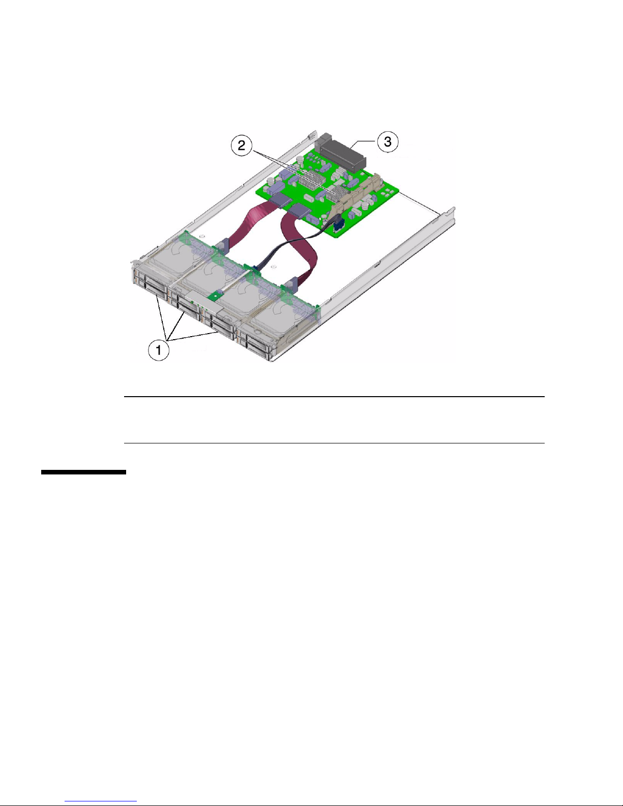
FIGURE 1-2 The Interior of the Sun Blade 6000 Disk Module
Figure Legend
1 Disk drives
2 SAS Expanders
3 Connectors to chassis midplane
The Server Module SAS Host Bus
Adapter
The disks on a Sun Blade 6000 Disk Module are controlled by a SAS host bus adapter
on the server module. This adapter can be either an on-board chip or a RAID
Expansion Module card.
used to control disks. Server modules can have either no disks, or up to four disks of
their own. The SAS host bus adapter on the server module controls its own disks as
well as disks on the disk module. The disks on the disk module are connected to the
SAS host bus adapter through two SAS-NEM modules, providing a dual path to
each SAS disk.
FIGURE 1-3 shows the key components of a server that are
4 Sun Blade 6000 Disk Module Installation Guide • June 2009
Page 13
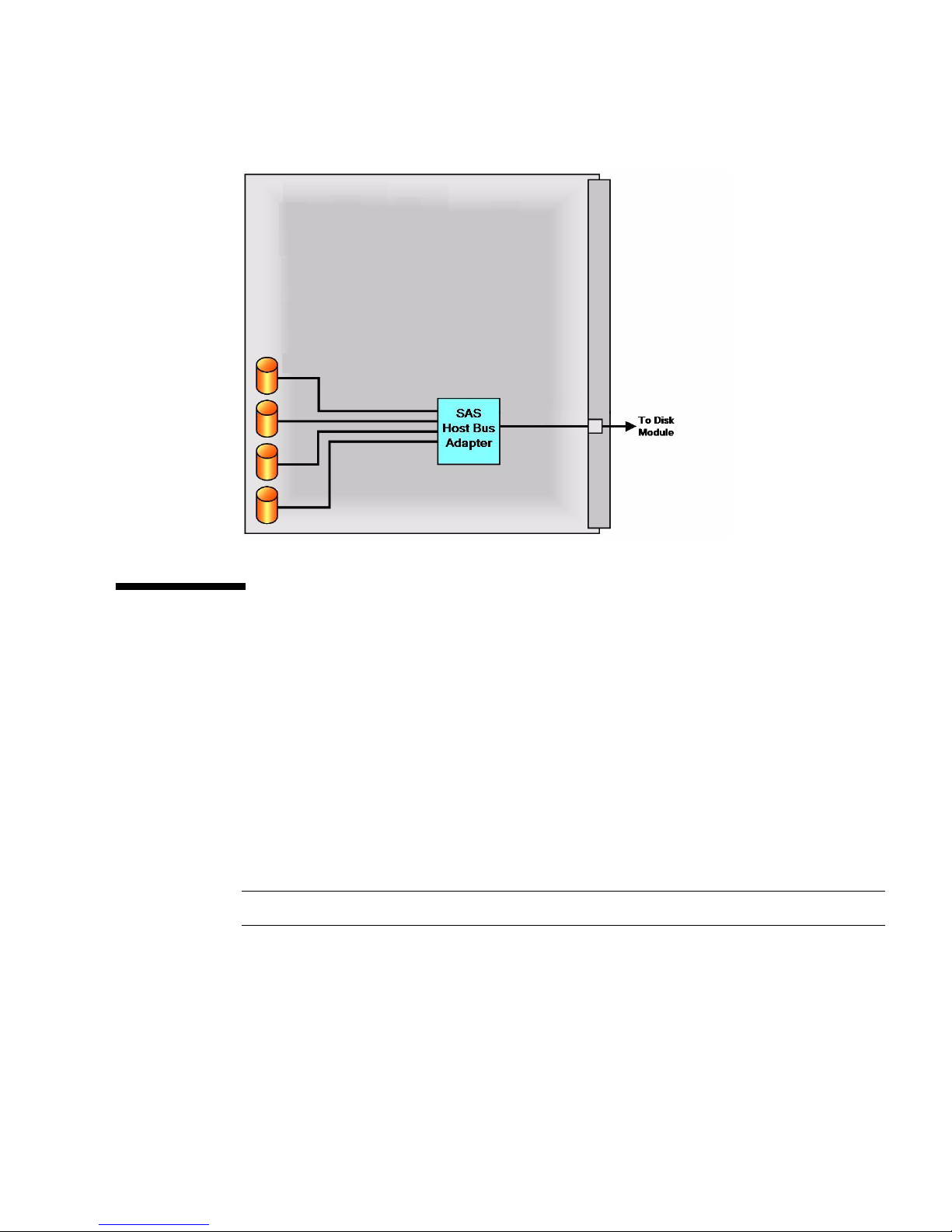
FIGURE 1-3 Connection of SAS Host Bus Adapter for Sun Blade Servers
Server Modules and Disk Modules in a
Chassis
The Sun Blade 6000 Disk Module can interoperate with any one of the supported
server blades: X6220, X6240, X6250, X6270, X6440, X6450, T6300, T6320, and T6340.
The server blades and disk blades must be placed in the chassis in pairs. The pairs
must be in slots 0+1, 2+3, 4+5, 6+7, or 8+9. No other combination of slots can be
used. When (facing the front of the system chassis) the server blade is on the left, a
server blade in slot n (n is an even number) sees its own on-blade disks and all the
disks in a disk blade in slot n+1, but no other disks.
Note – The server blade should be placed on the left.
FIGURE 1-4 shows a Sun Blade 6000 Modular System chassis, fully loaded with server
modules and disk modules:
Chapter 1 Using Sun Blade 6000 Disk Modules with Server Modules: An Overview 5
Page 14

FIGURE 1-4 Front View of Chassis Filled with Server and Disk Module Blade Pairs
Counting from the left, server blades are in slots 0, 2, 4, 6, and 8. Disk blades are in
slots 1, 3, 5, 7, and 9.
6 Sun Blade 6000 Disk Module Installation Guide • June 2009
Page 15

CHAPTER
2
Setting Up the Disk Module
Hardware
This chapter contains the following topics:
■ “Important Notice” on page 7
■ “Installation Overview” on page 7
■ “Inserting the Disk Module” on page 8
■ “The Sun Blade 6000 Disk Module Front Panel” on page 10
Important Notice
Before installing your disk module, please read the Sun Blade 6000 Disk Module
Configuration Guide (part number 820-6547). There is a checklist of steps that need to
be performed when you are configuring a chassis with server and disk blade pairs. It
also contains important information about using the disk blade with different
servers, operating systems, and host bus adapters.
Installation Overview
Caution – Server modules that use LSI host bus adapters and that are intended for
use with a disk module should be inserted before the disk module. Then, prior to
inserting the disk module for the first time, you must erase the “non-present”
mappings in the host bus adapter using the lsiutil utility described in the Sun
7
Page 16
Blade 6000 Disk Module Administration Guide (part number 820-4922).
If the server blade uses an Adaptec host bus adapter, this procedure is not necessary.
You should insert the server modules in even-numbered slots. Then, insert the
companion disk modules in the odd-numbered slot to the right of the server
modules. The 10 chassis slots are numbered 0 through 9 from the left to the right,
viewed facing the front of the chassis. See “Server Modules and Disk Modules in a
Chassis” on page 5.
You can insert the disk module into the chassis whether or not the chassis is
powered on. The Sun Blade 6000 Disk Module is hot-pluggable.
The disk module receives its power directly from the chassis. There is no power
switch on the module itself.
If the service processor software on the chassis, called the Chassis Management
Module (CMM) Integrated Lights Out Manager (ILOM), is already configured, it
should automatically recognize the disk module and the state of the disk module
LEDs.
Inserting the Disk Module
Caution – Before handling components, attach an electrostatic discharge (ESD)
wrist strap to bare metal on the chassis. Both the front and back of the chassis have
grounded locations. The system’s printed circuit boards and disk drives contain
components that are extremely sensitive to static electricity.
▼ To Insert the Disk Module
1. Locate the desired slot in the chassis.
2. Remove the filler panel.
Pull the lever out and eject the filler panel.
Caution – If the chassis is powered on, insert the disk module within 60 seconds of
removing the filler panel. Otherwise chassis cooling may be compromised.
8 Sun Blade 6000 Disk Module Installation Guide • June 2009
Page 17

Note – Filler panels should remain in any unused slots because they ensure that the
chassis maintains the proper cooling and complies with FCC limits on
electromagnetic interference (EMI).
3. Open the ejectors as far as possible without forcing them.
4. Position the disk module vertically so that the ejectors are on the right, as seen
from the front of the module.
The following illustrations show the disk module being inserted into the Sun
Blade 6000 Modular System. Your chassis might differ (see
FIGURE 2-1 Inserting the Disk Module Into the Chassis
FIGURE 2-1 [1]).
5. Push the disk module into the slot until the disk module stops (see FIGURE 2-1
[2]).
Chapter 2 Setting Up the Disk Module Hardware 9
Page 18

6. Rotate the ejectors down until they snap into place.
The disk module should now be flush with the chassis (although the disk drives
stick out about 1.5 mm) and the ejectors are locked (see
FIGURE 2-1 [3, 4]).
The Sun Blade 6000 Disk Module Front
Panel
The front panel of the Sun Blade 6000 Disk Module is shown in FIGURE 2-2.
FIGURE 2-2 Sun Blade 6000 Disk Module Front Panel
10 Sun Blade 6000 Disk Module Installation Guide • June 2009
Page 19

Refer to TABLE 2-1 for descriptions of the LED behavior.
TABLE 2-1 Front Panel LED Functions
LED Name Description
1 Combined Locate button and
LED (white)
This LED helps you to identify which module you are
working on in a chassis full of servers.
• Push and release this button to make the Locate
LED blink for 30 minutes.
• When the Locate LED is blinking, push and release
this button to make the Locate LED stop blinking.
• Hold down the button for 5 seconds to initiate a
“push-to-test” mode that illuminates all other LEDs
for 15 seconds.
• This LED can also be made to blink from a remote
system using the CMM ILOM. Refer to the Sun Blade
6000 Disk Module Administration Guide for details.
2 Ready-to-Remove LED (blue) • Not used.
3 Module Fault LED (amber) This LED has two states:
• On: An event has been acknowledged, and service
action is required.
• Off: Normal operation.
4 Module Activity LED (green) This LED has three states:
• On: Module is configured and online.
• Off: Module is not configured or is offline.
• Blinking: Module is configuring or a firmware flash
update is in progress.
5 Disk Drive Activity LED
(green)
This LED has three states:
• On: Power is on and disk is online.
• Off: Disk is offline.
• Blinking: Irregular blinking means normal disk
activity; steady, slow blink means RAID activity.
6 Disk Drive Fault and Locate
LED (amber)
This LED has four states:
• On: Disk fault. Service action required.
• Off: Normal operation.
• Slow blink: Disk failure predicted.
• Fast blink: Locate function activated.
7 Ready-to-Remove LED (blue) • Not used.
Chapter 2 Setting Up the Disk Module Hardware 11
Page 20

12 Sun Blade 6000 Disk Module Installation Guide • June 2009
Page 21
CHAPTER
3
Installing and Uninstalling Disks
This chapter contains these sections:
■ “Compatible Disk Drives” on page 13
■ “Inserting a Disk Drive” on page 14
■ “Replacing a Disk Drive” on page 17
Compatible Disk Drives
TABLE 3-1 lists the disk drives that have been tested for use in the Sun Blade 6000
Disk Module.
TABLE 3-1 Supported Disk Drives
Part Number (With
Capacity (GB) Speed (RPM)
32 N/A 540-7841-xx Intel SSD SATA
73 10K 540-7354-xx Fujitsu mecahnical SAS
73 10K 540-7354-xx Hitachi mechanical SAS
73 10K 540-7354-xx Seagate mechanical SAS
73 15K 540-7361-xx Seagate mechanical SAS
146 10K 540-7355-xx Fujitsu mechanical SAS
146 10K 540-7355-xx Hitachi mechanical SAS
146 10K 540-7355-xx Seagate mechanical SAS
146 10K 540-7864-xx Hitachi mechanical SAS
Bracket) Manufacturer Type SAS/SATA
13
Page 22

TABLE 3-1 Supported Disk Drives (Continued)
Part Number (With
Capacity (GB) Speed (RPM)
146 10K 540-7868-xx Seagate mechanical SAS
300 10K 540-7868-xx Seagate mechanical SAS
300 10K 540-7869-xx Hitachi mechanical SAS
Bracket) Manufacturer Type SAS/SATA
The following rules apply when mixing drives in the disk blade:
■ You can mix SAS disk drives with different specifications in a disk blade.
■ You can have up to eight SSD drives in the disk blade (for HBA requirements
when using SSDs, see the Sun Blade 6000 Disk Module Administration Guide,
820-4922).
Note – Currently, the X4620A Sun Blade RAID 5 Expansion Module (Intel/Adaptec)
does not support SSDs. Check the Sun Blade 6000 Disk Module Product Notes
(820-1709) for the latest information.
■ Do not mix SSD and mechanical drives in a single RAID volume.
■ Do not mix SATA and SAS drives in a single RAID volume
■ Hot spares assigned to a volume must be of the same type as disks in the RAID
volume (SAS or SATA; mechanical or SSD)
Inserting a Disk Drive
Caution – Before handling components, insert an antistatic wrist strap into the
antistatic grounding receptacle on the front of the chassis. The system’s disk drives
contain components that are extremely sensitive to static electricity.
▼ To Insert a Disk
1. Remove the filler bracket from the disk drive slot (see FIGURE 3-1).
14 Sun Blade 6000 Disk Module Installation Guide • June 2009
Page 23
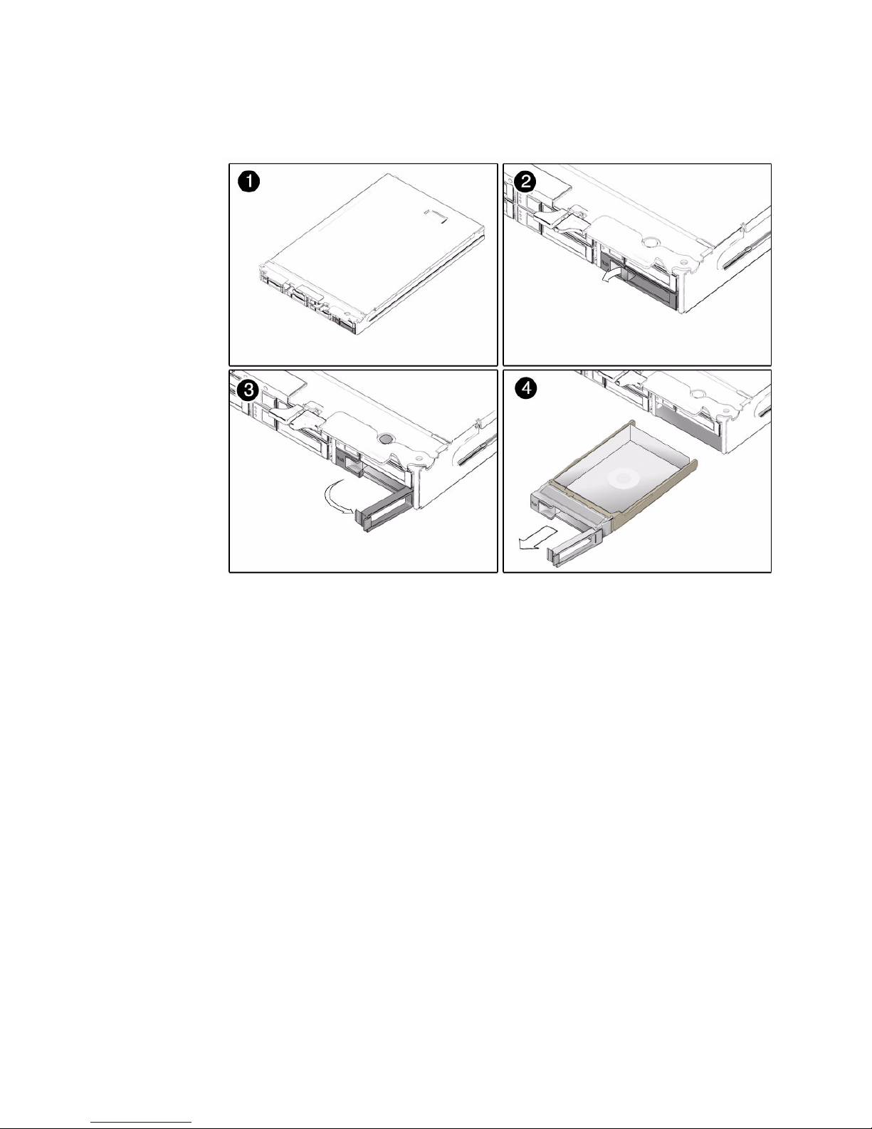
FIGURE 3-1 Removing a Disk Drive Slot Filler
2. Press the release button on the face of the disk drive to open the spring-loaded
securing latch (see
FIGURE 3-2).
Chapter 3 Installing and Uninstalling Disks 15
Page 24

FIGURE 3-2 Sun Blade 6000 Disk Module Drive
Figure Legend
1 Release button
2 Spring-loaded securing latch
3. Firmly push the disk drive into its bay in the disk module until it stops and the
securing latch partially closes.
Caution – Do not force the securing latch. When you have pushed the disk drive
into its bay in the disk module far enough, the securing latch will partially close and
you should be able to finish closing the latch easily. If the securing latch does not
close easily, firmly push the drive in further until the latch does close easily.
4. Close the securing latch all the way to complete the insertion.
16 Sun Blade 6000 Disk Module Installation Guide • June 2009
Page 25

Replacing a Disk Drive
On occasion, a disk drive might fail. The status of the drive is indicated by its LEDs,
as shown in
TABLE 3-2 Drive Status LED Indicators
LED Name Description
Disk Drive Activity LED (green) This LED has three states:
TABLE 3-2.
• On: Power is on and disk is present.
• Off: Disk is offline or absent.
• Blinking: Irregular blinking means normal disk activity.
Steady, slow blink means RAID activity.
Disk Drive Fault and Locate LED
(amber)
Ready-to-Remove LED (blue) • Not used.
This LED has four states:
• On: Disk fault. Service action required.
• Off: Normal operation.
• Slow blink: Disk failure predicted.
• Fast blink: Locate function activated.
A single disk failure does not cause a data failure when disks are configured as a
mirrored RAID volume. When there is no hot-spare assigned to the mirror, the
failed disk can be hot-swapped; when the new disk is inserted, the contents are
automatically rebuilt from the rest of the array with no need to reconfigure the RAID
parameters.
If the mirror was configured with a hot-spare, the mirror is automatically rebuilt
with the hot-spare.
Caution – Possible data loss: You can remove the failed disk while the mirror is
rebuilt to the hot-spare, but you must not insert a new disk in its place until the
rebuilding of the mirror is completed. While data is being rebuilt, the green LED on
the remaining drives will blink slowly. The rebuild process can take a number of
hours for large mirrors.
Caution – Possible data loss: You must not insert a disk that has been previously
configured with a RAID volume into a new RAID volume. Before permanently
removing a disk that is part of an active RAID volume, use the appropriate RAID
tool to delete the RAID volume from the disk.
Chapter 3 Installing and Uninstalling Disks 17
Page 26

▼ To Replace a Disk
The Sun Blade 6000 Disk Module disks can be replaced by users. Follow these steps
to remove and replace a disk drive:
1. Observe the front panel disk drive LEDs and identify the defective disk as
indicated by its fault LED (see “The Sun Blade 6000 Disk Module Front Panel”
on page 10).
2. Execute software commands, if appropriate, to isolate and prepare the disk
drive for removal.
3. Press the button on the face of the disk to release the spring-loaded securing
latch. See
4. Grasp the securing latch and remove the disk from the drive bay.
FIGURE 3-3 and FIGURE 3-4.
You can always remove a disk drive when it is out of the chassis (see
FIGURE 3-3).
Disks in the Sun Blade 6000 Disk Module are hot-pluggable, so you can also
remove a disk when the disk module is installed in the chassis (see
FIGURE 3-4).
Caution – Slots should always contain either a disk drive or a filler in order to
maintain adequate air flow. Do not operate the system with slots that are empty.
Always insert a filler when you remove a disk drive from a slot.
FIGURE 3-3 Removing the Disk Drive After Removing the Disk Module
18 Sun Blade 6000 Disk Module Installation Guide • June 2009
Page 27

FIGURE 3-4 Removing the Disk Drive Without Removing the Disk Module
Chapter 3 Installing and Uninstalling Disks 19
Page 28

20 Sun Blade 6000 Disk Module Installation Guide • June 2009
Page 29

CHAPTER
4
The SAS-NEM
This chapter describes the functionality of a SAS-NEM as it pertains to connecting
server and disk modules.
Installation of SAS-NEMs is covered briefly in this manual because a Sun Blade 6000
Disk Module does not work without the presence of a SAS-NEM.
SAS-NEMs are fully described in their own documentation. Refer to the Sun Blade
6000 Disk Module Administration Guide (820-4922) for a complete list of supported
SAS-NEMs.
This chapter contains these topics:
■ “Overview of the SAS-NEM” on page 21
■ “Inserting a SAS-NEM” on page 22
■ “Removing a SAS-NEM” on page 23
■ “Replacing a SAS-NEM” on page 25
Overview of the SAS-NEM
There are various Network Express Modules that can be plugged into the Sun Blade
6000 Modular System chassis. SAS-NEMs are those that contain circuitry to provide
multiple SAS connections to disk drives. All Network Express Modules, including
SAS-NEMs, plug into the Network Express Module slots on the back of the chassis
and are hot-pluggable.
21
Page 30

Inserting a SAS-NEM
You can insert either one or two SAS-NEMs in the Sun Blade 6000 chassis. If you
insert only one, it must go in the lower slot (NEM 0).
▼ To Insert a SAS-NEM
1. From the rear of the chassis, remove the NEM filler panel.
2. Align the SAS-NEM with the vacant NEM slot.
Ensure that:
■ The SAS-NEM ejector levers are on the top of the module, facing you.
■ The SAS-NEM ejector levers are fully opened.
3. Slide the SAS-NEM into the vacant NEM chassis slot until you feel it stop.
FIGURE 4-1 shows how to install a SAS-NEM.
22 Sun Blade 6000 Disk Module Installation Guide • June 2009
Page 31

FIGURE 4-1 Installing a SAS-NEM
4. Complete the installation by closing the ejector levers to secure the SAS-NEM
in the chassis.
Removing a SAS-NEM
If a Network Express Module (SAS-NEM) fails, you need to replace it. You can
remove and replace a SAS-NEM from a powered-on chassis using a hot-plug
operation, as well as from a powered-off chassis.
Caution – Make sure that none of the server blades are actively accessing Ethernet
ports or disk drives in a disk module before you remove the SAS-NEM.
Chapter 4 The SAS-NEM 23
Page 32

▼ To Remove a SAS-NEM
1. In the rear of the chassis, locate the SAS-NEM that you want to remove.
2. Remove all cables that are plugged into the SAS-NEM.
3. Press together and hold the ejector buttons on both the right and left ejector
levers.
FIGURE 4-2 shows how to remove a SAS-NEM.
FIGURE 4-2 Removing a SAS-NEM
4. To unlatch the SAS-NEM from the chassis, open the ejector levers by extending
them outward.
5. Holding the opened ejector levers, pull the SAS-NEM toward you until you can
pull the rest of the module out by hand.
Caution – If the chassis is powered on and you are not replacing the SAS-NEM
within 60 seconds, install a NEM filler panel to ensure proper system operation.
24 Sun Blade 6000 Disk Module Installation Guide • June 2009
Page 33

Replacing a SAS-NEM
If a SAS-NEM fails it must be replaced immediately. You cannot simply replace the
failed SAS-NEM with a new one. You must follow the procedure as described in the
SAS-NEM documentation.
Chapter 4 The SAS-NEM 25
Page 34

26 Sun Blade 6000 Disk Module Installation Guide • June 2009
Page 35

Index
C
cautions
do not force HDD latch, 16
use electrostatic discharge wrist strap, 8, 14
D
disk drive status LEDs, 11
disk drives
compatible, 13
inserting, 14
replacing, 17
status LEDs, 17
disk module
front panel, 10
inserting, 8
disk modules and server modules in a chassis, 5
F
figures
Inserting the Disk Module Into the Chassis, 9
Installing a SAS-NEM, 23
Removing a SAS-NEM, 24
Removing the Disk Drive After Removing the
Disk Module, 18
Removing the Disk Drive Without Removing the
Disk Module, 19
Sun Blade 6000 Disk Module Front Panel, 10
front panel LEDs, 11
I
indicators. See LEDs, 11
inserting a SAS-NEM, 22
inserting the disk module, 8
installation overview, 7
L
LEDs
disk drive status, 11, 17
front panel, 11
locate, 11
Module Activity, 11
Service Action Required, 11
Locate LED and button, 11
M
Module Activity LED, 11
N
NEM. See SAS-NEM, 21
O
overview
Sun blade 6000 Disk Module, 2
overview of installation, 7
overview of the SAS-NEM, 21
P
product updates, where to get, v
R
related documentation, v
removing a SAS-NEM, 23
27
Page 36

S
SAS host bus adapter, 4
SAS-NEM
inserting, 22
overview, 21
removing, 23
server modules and disk modules in a chassis, 5
Service Action Required LED, 11
Sun Blade 6000 Disk Module, overview, 2
T
terminology, 1
typographic conventions, vi
28 Sun Blade 6000 Disk Module Installation Guide • June 2009
 Loading...