

Page 1

Sun Blade™ 1500 Service,
Diagnostics, and Troubleshooting
Manual
(Silver)
Silver
Sun Microsystems, Inc.
www.sun.com
Part No. 817-5127-11
December 2004, Revision A
Submit comments about this document at: http://www.sun.com/hwdocs/feedback
Page 2

Copyright 2004 Sun Microsystems, Inc., 4150 Network Circle, Santa Clara, California 95054, U.S.A. All rights reserved. Sun Microsystems, Inc.
has intellectual property rights relating to technology embodied in the product that is described in this document. In particular, and without
limitation, these intellectual property rights might include one or more of the U.S. patents listed at http://www.sun.com/patents and one
or more additional patents or pending patent applications in the U.S. and in other countries.
This document and the product to which it pertains are distributed under licenses restricting their use, copying, distribution, and
decompilation. No part of the product or of this document may be reproduced in any form by any means without prior written authorization of
Sun and its licensors, if any.
Third-party software, including font technology, is copyrighted and licensed from Sun suppliers.
Parts of the product might be derived from Berkeley BSD systems, licensed from the University of California. UNIX is a registered trademark in
the U.S. and in other countries, exclusively licensed through X/Open Company, Ltd.
Sun, Sun Microsystems, the Sun logo, docs.sun.com, Sun Blade, SunVTS, SunSolve, SunFastEthernet, Sun Quad FastEthernet, SunPCi,
SunHSI/P, OpenBoot, SunSwift, StorEdge, and Solaris are trademarks or registered trademarks of Sun Microsystems, Inc. in the U.S. and in
other countries.
All SPARC trademarks are used under license and are trademarks or registered trademarks of SPARC International, Inc. in the U.S. and in other
countries. Products bearing SPARC trademarks are based upon an architecture developed by Sun Microsystems, Inc. The Energy Star logo is a
registered trademark of the EPA. FireWire and the FireWire logo are trademarks of Apple Computer, Inc., used under license.
The OPEN LOOK and Sun™ Graphical User Interface was developed by Sun Microsystems, Inc. for its users and licensees. Sun acknowledges
the pioneering efforts of Xerox in researching and developing the concept of visual or graphical user interfaces for the computer industry. Sun
holds a non-exclusive license from Xerox to the Xerox Graphical User Interface, which license also covers Sun’s licensees who implement OPEN
LOOK GUIs and otherwise comply with Sun’s written license agreements.
As an Energy Star partner, Sun Microsystems, Inc. has determined that configurations of this
product that bear the Energy Star Logo meet the Energy Star guidelines for energy efficiency.
Use, duplication, or disclosure by the U.S. Government is subject to restrictions set forth in the Sun Microsystems, Inc. license agreements and as
provided in DFARS 227.7202-1(a) and 227.7202-3(a) (1995), DFARS 252.227-7013(c)(1)(ii) (Oct. 1998), FAR 12.212(a) (1995), FAR 52.227-19, or
FAR 52.227-14 (ALT III), as applicable.
DOCUMENTATION IS PROVIDED "AS IS" AND ALL EXPRESS OR IMPLIED CONDITIONS, REPRESENTATIONS AND WARRANTIES,
INCLUDING ANY IMPLIED WARRANTY OF MERCHANTABILITY, FITNESS FOR A PARTICULAR PURPOSE OR NON-INFRINGEMENT,
ARE DISCLAIMED, EXCEPT TO THE EXTENT THAT SUCH DISCLAIMERS ARE HELD TO BE LEGALLY INVALID.
Copyright 2004 Sun Microsystems, Inc., 4150 Network Circle, Santa Clara, California 95054, Etats-Unis. Tous droits réservés. Sun Microsystems,
Inc. a les droits de propriété intellectuels relatants à la technologie incorporée dans le produit qui est décrit dans ce document. En particulier, et
sans la limitation, ces droits de propriété intellectuels peuvent inclure un ou plus des brevets américains énumérés à
http://www.sun.com/patents et un ou les brevets plus supplémentaires ou les applications de brevet en attente dans les Etats-Unis et
dans les autres pays.
Ce produit ou document est protégé par un copyright et distribué avec des licences qui en restreignent l’utilisation, la copie, la distribution, et la
décompilation. Aucune partie de ce produit ou document ne peut être reproduite sous aucune forme, parquelque moyen que ce soit, sans
l’autorisation préalable et écrite de Sun et de ses bailleurs de licence, s’il y ena.
Le logiciel détenu par des tiers, et qui comprend la technologie relative aux polices de caractères, est protégé par un copyright et licencié par des
fournisseurs de Sun.
Des parties de ce produit pourront être dérivées des systèmes Berkeley BSD licenciés par l’Université de Californie. UNIX est une marque
déposée aux Etats-Unis et dans d’autres pays et licenciée exclusivement par X/Open Company, Ltd.
Sun, Sun Microsystems, le logo Sun, docs.sun.com, Sun Blade, SunVTS, SunSolve,SunFastEthernet, Sun Quad FastEthernet, SunPCi, SunHSI/P,
OpenBoot, SunSwift, StorEdge, et Solaris sont des marques de fabrique ou des marques déposées de Sun Microsystems, Inc. aux Etats-Unis et
dans d’autres pays.
Toutes les marques SPARC sont utilisées sous licence et sont des marques de fabrique ou des marques déposées de SPARC International, Inc.
aux Etats-Unis et dans d’autres pays. Les produits protant les marques SPARC sont basés sur une architecture développée par Sun
Microsystems, Inc. FireWire et le logo de FireWire sont des marques de’pose’es de Applex Computer, Inc., utilise’ sous le permis.
L’interface d’utilisation graphique OPEN LOOK et Sun™ a été développée par Sun Microsystems, Inc. pour ses utilisateurs et licenciés. Sun
reconnaît les efforts de pionniers de Xerox pour la recherche et le développment du concept des interfaces d’utilisation visuelle ou graphique
pour l’industrie de l’informatique. Sun détient une license non exclusive do Xerox sur l’interface d’utilisation graphique Xerox, cette licence
couvrant également les licenciées de Sun qui mettent en place l’interface d ’utilisation graphique OPEN LOOK et qui en outre se conforment
aux licences écrites de Sun.
LA DOCUMENTATION EST FOURNIE "EN L’ÉTAT" ET TOUTES AUTRES CONDITIONS, DECLARATIONS ET GARANTIES EXPRESSES
OU TACITES SONT FORMELLEMENT EXCLUES, DANS LA MESURE AUTORISEE PAR LA LOI APPLICABLE, Y COMPRIS NOTAMMENT
TOUTE GARANTIE IMPLICITE RELATIVE A LA QUALITE MARCHANDE, A L’APTITUDE A UNE UTILISATION PARTICULIERE OU A
L’ABSENCE DE CONTREFAÇON.
Please
Recycle
Page 3

Contents
Preface xxxi
1. Start Here 1–1
1.1 Diagnostic Tools Available 1–1
1.2 About Flowcharts 1–3
1.3 How to Use This Manual 1–4
2. Product Description 2–1
2.1 Product Overview 2–1
2.2 External System Description 2–3
2.3 Replaceable Components 2–7
2.4 Supported Sun Monitors 2–10
3. Basic Troubleshooting 3–1
3.1 Power-On Sequence 3–1
3.2 Display and Audio Responses 3–2
3.2.1 Displayed Screens 3–2
3.2.2 Displayed Messages 3–5
3.2.3 Audio Responses 3–12
3.3 Troubleshooting Commands 3–15
3.3.1 iostat Command 3–15
iii
Page 4

3.3.2 prtdiag Command 3–18
3.3.3 prtconf Command 3–20
3.3.4 netstat Command 3–23
3.3.5 ping Command 3–25
3.3.6 ps Command 3–27
3.3.7 prstat Command 3–29
4. Troubleshooting Flowcharts 4–1
4.1 Power-On Flowchart 4–2
4.2 Start Up Problems 4–5
4.2.1 Power Problem 4–6
4.2.2 Hard Drive Problem 4–8
4.2.3 System Fan Problem 4–9
4.2.4 USB Problem 4–10
4.2.5 Audio Output Problem 4–12
4.2.6 Monitor Problem 4–14
4.2.7 Network Problem 4–17
4.2.8 Keyboard Problem 4–19
4.2.9 Login Problem 4–20
4.2.10 Graphical User Interface Problem 4–22
4.2.11 Data Access and Running Applications Problem 4–23
4.3 Storage Problems 4–24
4.3.1 Optical Drive Problem 4–25
4.3.2 PCI Card Problem 4–28
4.3.3 IEEE 1394 Problem 4–30
4.3.4 Smart Card Reader Problem 4–32
4.4 Advanced Problems 4–33
4.4.1 Motherboard Problem 4–34
4.4.2 Memory Problem 4–37
iv Sun Blade 1500 Service, Diagnostics, and Troubleshooting Manual • December 2004
Page 5

4.4.3 NVRAM Problem 4–39
4.4.4 Battery Problem 4–40
5. Introduction to Advanced Troubleshooting 5–1
5.1 NVRAM 5–1
5.2 Obtaining the ok Prompt for Testing 5–2
5.3 Diagnostic Tests Summary 5–3
5.4 Power-On Self-Test 5–4
5.4.1 POST Overview 5–4
5.4.2 Configuring POST Output 5–4
5.5 OpenBoot PROM 5–5
5.5.1 OpenBoot PROM Overview 5–5
5.5.2 OpenBoot Diagnostics 5–6
5.6 SunVTS Software 5–6
5.6.1 SunVTS Overview 5–6
5.6.2 SunVTS Requirements 5–6
5.6.3 SunVTS Documentation 5–7
5.7 Sun Install Check 5–7
5.7.1 Sun Install Check Overview 5–7
5.7.2 Downloading Sun Install Check 5–7
6. NVRAM 6–1
6.1 Changing NVRAM Configuration Parameter Values 6–1
6.1.1 Displaying and Changing Parameter Values 6–2
6.1.2 Configuration Parameter Default Values 6–4
6.2 Setting NVRAM Security Mode 6–7
6.3 eeprom Command 6–8
6.4 Key Commands 6–9
6.4.1 Stop-A Command 6–10
Contents v
Page 6

6.4.2 Stop-N Equivalent Command Procedure 6–10
7. Power-On Self-Test 7–1
7.1 The post Command 7–1
7.1.1 Diagnostic Levels 7–2
7.1.2 Output Verbosity 7–2
7.2 Setting Up for POST 7–2
7.2.1 Verify the Baud Rate 7–3
7.2.2 Disable Diagnostics and Auto Boot 7–3
7.2.3 Obtain the ok Prompt 7–4
7.2.4 Configure an External Display Device 7–4
7.2.5 Run POST 7–6
7.3 POST Output 7–6
7.3.1 post min min 7–7
7.3.2 post min normal 7–7
7.3.3 post min max 7–8
7.3.4 post max min 7–12
7.3.5 post max normal 7–12
7.3.6 post max max 7–13
7.4 Analyzing POST Results 7–18
7.4.1 Error Messages 7–18
7.4.2 Warning Messages 7–20
7.4.3 Info Messages 7–20
8. OpenBoot PROM 8–1
8.1 OpenBoot PROM Utilities 8–1
8.1.1 show-devs Utility 8–2
8.1.2 watch-net Utility 8–2
8.1.3 probe-ide Utility 8–3
vi Sun Blade 1500 Service, Diagnostics, and Troubleshooting Manual • December 2004
Page 7

8.1.4 banner Utility 8–3
8.1.5 watch-clock Utility 8–4
8.1.6 date Utility 8–4
8.1.7 .version Utility 8–4
8.2 OpenBoot Diagnostics 8–5
8.2.1 Starting OpenBoot Diagnostics 8–5
8.2.2 obdiag Menu 8–6
8.2.3 Configuring OpenBoot Diagnostics 8–7
8.2.4 Initiating a Test 8–7
8.2.5 Test Output 8–7
8.2.6 OpenBoot Diagnostics Tests 8–8
9. SunVTS 9–1
9.1 Installing SunVTS 9–1
9.2 Exercising System Components Using SunVTS Software 9–1
9.2.1 Connection Mode 9–2
9.2.2 Connection Mode Component Testing 9–2
9.2.3 Functional Mode 9–6
9.2.4 Functional Mode Component Testing 9–6
9.3 Further SunVTS Testing 9–10
10. Preparing to Replace Components 10–1
10.1 Safety Information 10–1
10.1.1 Safety Precautions 10–2
10.1.2 Safety Symbols 10–2
10.1.3 Electrostatic Discharge Safety 10–2
10.2 Required Tools 10–3
10.3 Powering Off the Workstation 10–4
10.3.1 Identifying the Power Button 10–4
Contents vii
Page 8

10.3.2 Powering Off Methods 10–5
10.4 Removing the Access Panel 10–12
10.5 Removing the Bezel 10–14
10.6 Positioning the Chassis 10–16
10.7 Finding Your Replacement Procedures 10–18
11. Replacing the Motherboard and Associated Components 11–1
11.1 Replacing the DIMMs 11–2
11.1.1 Identifying the DIMMs 11–2
11.1.2 Removing DIMMs 11–3
11.1.3 Installing DIMMs 11–7
11.1.4 OpenBoot PROM Memory Message 11–12
11.2 Replacing the CPU Fan and Heat Sink Assembly 11–13
11.2.1 Identifying the CPU Fan and Heat Sink Assembly 11–13
11.2.2 Removing the CPU Fan and Heat Sink Assembly 11–14
11.2.3 Installing the CPU Fan and Heat Sink Assembly 11–18
11.3 Replacing the Battery 11–22
11.3.1 Identifying the Battery 11–23
11.3.2 Removing the Battery 11–23
11.3.3 Installing the Battery 11–24
11.4 Replacing the NVRAM 11–25
11.4.1 Identifying the NVRAM 11–26
11.4.2 Removing the NVRAM 11–26
11.4.3 Installing the NVRAM 11–27
11.5 Replacing the PCI Cards 11–28
11.5.1 Identifying the PCI Cards 11–29
11.5.2 Removing a PCI Card 11–30
11.5.3 General PCI Card Guidelines 11–33
11.5.4 Special Considerations for Graphics Accelerators 11–34
viii Sun Blade 1500 Service, Diagnostics, and Troubleshooting Manual • December 2004
Page 9

11.5.5 Installing a PCI Card 11–38
11.6 Replacing the Motherboard 11–43
11.6.1 Identifying the Motherboard 11–44
11.6.2 Removing the Motherboard 11–46
11.6.3 Installing the Motherboard 11–50
12. Replacing Storage Devices 12–1
12.1 Replacing a Hard Drive 12–2
12.1.1 Identifying the Hard Drive 12–2
12.1.2 Removing a Hard Drive 12–3
12.1.3 Installing the Hard Drive 12–6
12.2 Replacing the Optical Drive 12–9
12.2.1 Identifying the Optical Drive 12–10
12.2.2 Removing the Optical Drive 12–10
12.2.3 Installing the Optical Drive 12–12
12.3 Replacing the Smart Card Reader 12–15
12.3.1 Identifying the Smart Card Reader 12–15
12.3.2 Removing the Smart Card Reader 12–16
12.3.3 Installing the Smart Card Reader 12–20
13. Replacing Chassis Components 13–1
13.1 Replacing the Power Supply 13–2
13.1.1 Identifying the Power Supply 13–2
13.1.2 Removing the Power Supply 13–3
13.1.3 Installing the Power Supply 13–5
13.2 Replacing the Front Fan 13–8
13.2.1 Identifying the Front Fan 13–8
13.2.2 Removing the Front Fan 13–9
13.2.3 Installing the Front Fan 13–11
Contents ix
Page 10

13.3 Replacing the Rear Fan 13–15
13.3.1 Identifying the Rear Fan 13–15
13.3.2 Removing the Rear Fan 13–16
13.3.3 Installing the Rear Fan 13–18
13.4 Replacing the DIMM Cooling Duct 13–22
13.4.1 Identifying the DIMM Cooling Duct 13–22
13.4.2 Removing the DIMM Cooling Duct 13–23
13.4.3 Installing the DIMM Cooling Duct 13–27
13.5 Replacing the Audio USB Board 13–30
13.5.1 Identifying the Audio USB Board 13–31
13.5.2 Removing the Audio USB Board 13–31
13.5.3 Installing the Audio USB Board 13–35
13.6 Replacing the Speaker 13–39
13.6.1 Identifying the Speaker 13–39
13.6.2 Removing the Speaker 13–40
13.6.3 Installing the Speaker 13–42
13.7 Replacing the PCI Card Support 13–45
13.7.1 Identifying the PCI Card Support 13–45
13.7.2 Removing the PCI Card Support 13–45
13.7.3 Installing the PCI Card Support 13–47
13.8 Replacing the Chassis Cross Brace 13–49
13.8.1 Identifying the Chassis Cross Brace 13–50
13.8.2 Removing the Chassis Cross Brace 13–51
13.8.3 Installing the Chassis Cross Brace 13–53
13.9 Replacing the Drive Rails 13–59
13.9.1 Identifying the Drive Rails 13–59
13.9.2 Removing the Drive Rails 13–59
13.9.3 Installing the Drive Rails 13–61
x Sun Blade 1500 Service, Diagnostics, and Troubleshooting Manual • December 2004
Page 11

14. Replacing Internal Cables 14–1
14.1 Replacing the Smart Card Reader Cable 14–3
14.1.1 Identifying the Smart Card Reader Cable 14–4
14.1.2 Removing the Smart Card Reader Cable 14–4
14.1.3 Installing the Smart Card Reader Cable 14–5
14.2 Replacing the Optical Drive Interface Cable 14–6
14.2.1 Identifying the Optical Drive Interface Cable 14–7
14.2.2 Removing the Optical Drive Interface Cable 14–7
14.2.3 Installing the Optical Drive Interface Cable 14–8
14.3 Replacing the Hard Drive Interface Cable 14–10
14.3.1 Identifying the Hard Drive Interface Cable 14–10
14.3.2 Removing the Hard Drive Interface Cable 14–11
14.3.3 Installing the Hard Drive Interface Cable 14–12
14.4 Replacing the IDE Power Cable 14–13
14.4.1 Identifying the IDE Power Cable 14–13
14.4.2 Removing the IDE Power Cable 14–14
14.4.3 Installing the IDE Power Cable 14–16
14.5 Replacing the Power Switch Assembly 14–17
14.5.1 Identifying the Power Switch Assembly 14–18
14.5.2 Removing the Power Switch Assembly 14–18
14.5.3 Installing the Power Switch Assembly 14–21
14.6 Replacing the Audio USB Board Cables 14–23
14.6.1 Identifying the Audio USB Board Cables 14–23
14.6.2 Removing the Audio USB Board Cables 14–24
14.6.3 Installing the Audio USB Board Cables 14–27
15. Finishing Component Replacement 15–1
15.1 Repositioning the Chassis 15–1
15.2 Installing the Bezel 15–2
Contents xi
Page 12

15.3 Installing the Access Panel 15–5
15.4 Powering On the Workstation 15–8
15.4.1 Reconnecting Power and External Peripherals 15–8
15.4.2 Choosing the Boot Mode 15–10
15.5 Verifying an Installation 15–11
16. Customizing Your System 16–1
16.1 Optional PCI Cards 16–1
16.2 Internal Component Upgrades 16–4
16.3 External Peripherals 16–5
A. Product Specifications A–1
A.1 Physical Specifications A–1
A.2 Electrical Specifications A–2
A.3 Acoustic Specifications A–2
A.4 Environmental Requirements A–2
A.5 Shock and Vibration Specifications A–3
B. Signal Descriptions B–1
B.1 External Connectors B–2
B.1.1 Audio Jacks B–2
B.1.2 IEEE 1394 Ports B–2
B.1.3 Parallel Port B–3
B.1.4 Serial Ports B–4
B.1.5 Twisted-Pair Ethernet Port B–5
B.1.6 USB Ports B–6
B.1.7 Video Ports B–7
B.2 Internal Connectors B–11
B.2.1 Fan Connectors B–11
B.2.2 Front Audio Connector B–12
xii Sun Blade 1500 Service, Diagnostics, and Troubleshooting Manual • December 2004
Page 13

B.2.3 Front USB Connector B–12
B.2.4 IDE Interface Connectors B–13
B.2.5 IDE Power Connector B–15
B.2.6 Power Supply Connectors B–15
B.2.7 Power Switch Connector B–18
B.2.8 Smart Card Reader Connector B–18
B.2.9 Speaker Connector B–19
C. Functional Description C–1
C.1 Hardware Architecture C–1
C.1.1 Component Overview C–1
C.1.2 System Block Diagram C–3
C.1.3 Enclosure C–3
C.2 Motherboard C–4
C.2.1 Motherboard Block Diagram C–4
C.2.2 Motherboard Layout Diagram C–5
C.2.3 Motherboard Jumpers C–8
C.3 CPU and Memory C–9
C.3.1 CPU Description C–9
C.3.2 Caches C–9
C.3.3 Memory Controller C–11
C.3.4 Memory Block Diagram C–11
C.3.5 DIMM Configurations C–13
C.3.6 Memory Interleaving C–13
C.4 Internal Interfaces and ASICs C–15
C.4.1 JBus Information C–15
C.4.2 JIO Information C–16
C.4.3 PCI Bus Information C–17
C.4.4 M1535D+ C–18
Contents xiii
Page 14

C.4.5 BCM5793 C–19
C.4.6 Other Buses C–20
C.5 Graphics Accelerators C–21
C.5.1 Sun XVR-600 C–21
C.5.2 Sun XVR-100 C–24
C.5.3 Sun XVR-1200 C–25
C.6 System Clocks and Interrupts C–28
C.6.1 Clock Generation C–28
C.6.2 Interrupt Map C–30
C.7 External Interfaces C–31
C.7.1 ATA 100 C–32
C.7.2 Smart Card Reader C–32
C.7.3 USB C–33
C.7.4 Audio C–33
C.7.5 PCI Slots C–33
C.7.6 IEEE 1394/USB 2 Combination Card C–34
C.7.7 Ethernet C–34
C.7.8 Parallel C–34
C.7.9 Serial C–34
C.8 System Thermal Management C–36
C.8.1 Cooling Fan Control C–36
C.9 System Power Management C–38
C.9.1 Energy Star C–38
C.9.2 Power Budget C–38
C.9.3 Peripheral Power Supply C–39
D. Power Management D–1
D.1 Power Management Overview D–1
D.2 Enabling Power Management D–2
xiv Sun Blade 1500 Service, Diagnostics, and Troubleshooting Manual • December 2004
Page 15

D.2.1 Scenarios for the Example Configuration D–4
D.2.2 Activating the Workstation From Low-Power Mode D–5
D.3 Disabling Power Management D–5
D.3.1 Disabling Hard Drive Power Management D–5
D.3.2 Disabling All System Power Management D–6
Glossary Glossary–1
Contents xv
Page 16

xvi Sun Blade 1500 Service, Diagnostics, and Troubleshooting Manual • December 2004
Page 17

Tables
TABLE 1-1 Summary of Diagnostic Tools 1–2
TABLE 1-2 Flowchart Elements 1–3
TABLE 2-1 Sun Blade 1500 Configured Features 2–2
TABLE 2-2 Bezel Overview, Sun Blade 1500 Workstation 2–5
TABLE 2-3 Rear Panel Overview, Sun Blade 1500 Workstation 2–7
TABLE 2-4 Sun Blade 1500 Replaceable Components 2–8
TABLE 2-5 Monitors supported by the Sun Blade 1500 Workstation 2–10
TABLE 3-1 Screen Images and What They Mean 3–2
TABLE 3-2 OpenBoot PROM Messages and Their Meaning 3–6
TABLE 3-3 Solaris Error Messages and Their Meanings 3–8
TABLE 3-4 Other Messages and Their Meaning 3–11
TABLE 3-5 System Sounds at Locations and What They Mean 3–12
TABLE 3-6 Options for iostat 3–16
TABLE 3-7 Options for prtdiag 3–18
TABLE 3-8 Options for prtconf 3–21
TABLE 3-9 Options for netstat 3–23
TABLE 3-10 Options for ping 3–26
TABLE 3-11 Options for ps 3–27
TABLE 3-12 Options for prstat 3–29
TABLE 5-1 Methods for Obtaining the ok Prompt 5–2
xvii
Page 18

TABLE 5-2 POST, OpenBoot Diagnostics, and SunVTS Tests Available for Components 5–3
TABLE 5-3 POST Diagnostic Levels 5–5
TABLE 5-4 POST Output Verbosity 5–5
TABLE 6-1 NVRAM Parameter Configuration Commands 6–2
TABLE 6-2 NVRAM Configuration Parameter Default Values 6–4
TABLE 6-3 security-mode Values and Their Enforcement Policy 6–7
TABLE 6-4 Stop-N Equivalent Configuration Parameters 6–11
TABLE 7-1 Test Performed at min and max Diagnostic Levels 7–2
TABLE 7-2 Output Seen at min, normal, and max Output Verbosity 7–2
TABLE 7-3 Serial Terminal Communication Parameters 7–4
TABLE 7-4 post min normal Output Comparison 7–7
TABLE 7-5 post min max Output Comparison 7–8
TABLE 7-6 post max normal Output Comparison 7–12
TABLE 7-7 post max max Output Comparison 7–13
TABLE 8-1 OpenBoot Diagnostics Test Usage 8–9
TABLE 9-1 Subsequent Steps to Test Components in Connection Mode 9–3
TABLE 9-2 Steps to Test Components in Functional Mode 9–7
TABLE 10-1 Init Command Shutdown Options 10–7
TABLE 10-2 Workstation Chassis Directional Terms 10–17
TABLE 10-3 Component Replacement Procedures 10–19
TABLE 11-1 DIMM Pair Configurations 11–3
TABLE 11-2 OpenBoot PROM Memory Check Actions 11–12
TABLE 11-3 CPU Fan Specifications 11–14
TABLE 11-4 Battery Specifications 11–23
TABLE 11-5 PCI Card Slot Specifications 11–29
TABLE 11-6 PCI Card Probe Order 11–35
TABLE 11-7 Motherboard Connectors and Descriptions 11–45
TABLE 12-1 Hard Drive Specifications 12–3
TABLE 13-1 Power Supply Specifications 13–3
TABLE 13-2 Front Fan Specifications 13–9
xviii Sun Blade 1500 Service, Diagnostics, and Troubleshooting Manual • December 2004
Page 19

TABLE 13-3 Rear Fan Specifications 13–16
TABLE 13-4 Speaker Specifications 13–40
TABLE 14-1 Power Switch Assembly Specifications 14–18
TABLE 16-1 Conditions for Installing Optional PCI Cards 16–2
TABLE 16-2 Sun Blade 1500 Internal Component Upgrades 16–4
TABLE 16-3 Conditions for Attaching External Peripherals 16–5
TABLE A-1 Sun Blade 1500 Physical Specifications A–1
TABLE A-2 Enclosure Interior Dimensions for Sun Blade 1500 Workstation A–1
TABLE A-3 Sun Blade 1500 Electrical Specifications A–2
TABLE A-4 Sun Blade 1500 Acoustic Specifications A–2
TABLE A-5 Sun Blade 1500 Environmental Requirements A–2
TABLE A-6 Sun Blade 1500 Shock and Vibration Values A–3
TABLE B-1 Audio Jack Pinouts B–2
TABLE B-2 IEEE 1394A Port Pinouts B–2
TABLE B-3 Parallel Port Pinouts B–3
TABLE B-4 Serial Port Pinouts B–4
TABLE B-5 Twisted-Pair Ethernet Port Pinouts B–5
TABLE B-6 Twisted-Pair Ethernet LED Status B–6
TABLE B-7 USB Port Pinouts B–6
TABLE B-8 Graphics Accelerator Connectors B–7
TABLE B-9 HD15 Video Output Port Pinouts B–8
TABLE B-10 DVI-I Video Output Port Pinouts B–8
TABLE B-11 BNC NTSC/PAL Video Output Port Pinouts B–9
TABLE B-12 Mini-DIN7 Stereoscopic Imager Interface Connector Pinouts B–9
TABLE B-13 DB-9 Out Stereoscopic Imager Interface Connector Pinouts B–10
TABLE B-14 DB-9 In Stereoscopic Imager Interface Connector Pinouts B–10
TABLE B-15 Fan Connectors FAN0 SYS, FAN1 SYS, and FAN2 Pinouts B–11
TABLE B-16 Front Audio Connector J13 AUDIO Pinouts B–12
TABLE B-17 Front USB Connector J19 USB Pinouts B–13
TABLE B-18 IDE Interface Connectors IDE PRI and IDE SEC Pinouts B–13
Tables xix
Page 20

TABLE B-19 IDE Power Connector IDE PWR Pinouts B–15
TABLE B-20 Power Supply Connector PS0 Pinouts B–16
TABLE B-21 Power Supply Connector PS1 Pinouts B–16
TABLE B-22 Power Supply Connector PS2 Pinouts B–17
TABLE B-23 Power Switch Connector J24 SW0 Pinouts B–18
TABLE B-24 Smart Card Reader Connector SCR0 Pinouts B–19
TABLE B-25 Speaker Connector SPK0 Pinouts B–19
TABLE C-1 Sun Blade 1500 Motherboard Locations and Common Terminology C–7
TABLE C-2 Correct Motherboard Jumper Settings C–8
TABLE C-3 Sun Blade 1500 Supported DIMM Configurations C–13
TABLE C-4 Interleaving Modes C–14
TABLE C-5 Sun XVR-600 Graphics Accelerator Monitor Screen Resolutions C–23
TABLE C-6 Sun XVR-100 Graphics Accelerator Monitor Screen Resolutions C–24
TABLE C-7 Sun XVR-1200 Graphics Accelerator Screen Resolutions C–27
TABLE C-8 Clock Frequencies C–29
TABLE C-9 Sun Blade 1500 Interrupt Map C–30
TABLE C-10 Smart Card Reader LED Status C–32
TABLE C-11 TPE LED Status C–34
TABLE C-12 Sun Blade 1500 Component Power Consumption C–38
TABLE C-13 Power Supplied at Various Interfaces C–39
TABLE D-1 Dtpower Power Management Modes D–1
TABLE D-2 First Scenario Timeline D–4
TABLE D-3 Second Scenario Timeline D–4
xx Sun Blade 1500 Service, Diagnostics, and Troubleshooting Manual • December 2004
Page 21

Figures
FIGURE 1-1 Start Here Flowchart 1–4
FIGURE 2-1 Monitor, Keyboard, Mouse, and Sun Blade 1500 Workstation 2–4
FIGURE 2-2 Bezel Overview, Sun Blade 1500 Workstation 2–5
FIGURE 2-3 Rear Panel Overview, Sun Blade 1500 Workstation 2–6
FIGURE 2-4 Exploded Diagram of Sun Blade 1500 Replaceable Components 2–8
FIGURE 3-1 Displayed Messages Flowchart 3–6
FIGURE 4-1 Power-On Flowchart 4–3
FIGURE 4-2 Power-On Flowchart (Continued) 4–4
FIGURE 4-3 Power Problem 4–6
FIGURE 4-4 Power Problem (Continued) 4–7
FIGURE 4-5 Hard Drive Problem 4–8
FIGURE 4-6 System Fan Problem 4–9
FIGURE 4-7 USB Problem 4–10
FIGURE 4-8 USB Problem (Continued) 4–11
FIGURE 4-9 Audio Output Problem 4–12
FIGURE 4-10 Audio Output Problem (Continued) 4–13
FIGURE 4-11 Monitor Problem 4–14
FIGURE 4-12 Monitor Problem (Continued) 4–15
FIGURE 4-13 Monitor Problem (Continued) 4–16
FIGURE 4-14 Network Problem 4–17
xxi
Page 22

FIGURE 4-15 Network Problem (Continued) 4–18
FIGURE 4-16 Keyboard Problem 4–19
FIGURE 4-17 Login Problem 4–20
FIGURE 4-18 Login Problem (Continued) 4–21
FIGURE 4-19 Graphical User Interface Problem 4–22
FIGURE 4-20 Data Access and Running Applications Problems 4–23
FIGURE 4-21 Optical Drive Problem 4–25
FIGURE 4-22 Optical Drive Problem (Continued) 4–26
FIGURE 4-23 Optical Drive Problem (Continued) 4–27
FIGURE 4-24 PCI Card Problem 4–28
FIGURE 4-25 PCI Card Problem (Continued) 4–29
FIGURE 4-26 IEEE 1394 Problem 4–30
FIGURE 4-27 IEEE 1394 Problem (Continued) 4–31
FIGURE 4-28 Smart Card Reader Problem 4–32
FIGURE 4-29 Motherboard Problem 4–34
FIGURE 4-30 Motherboard Problem (Continued) 4–35
FIGURE 4-31 Motherboard Problem (Continued) 4–36
FIGURE 4-32 Memory Problem 4–37
FIGURE 4-33 Memory Problem (Continued) 4–38
FIGURE 4-34 NVRAM Problem 4–39
FIGURE 4-35 Battery Problem 4–40
FIGURE 7-1 Crossover Cable Wiring Diagram 7–5
FIGURE 10-1 Required Tools 10–3
FIGURE 10-2 Power Button and Sleep Key Location and Identification 10–5
FIGURE 10-3 Disconnecting the Keyboard, Mouse, Monitor, and Network Connections 10–8
FIGURE 10-4 Pressing the Power Button 10–10
FIGURE 10-5 Removing the Power Cord 10–11
FIGURE 10-6 Loosening the Screws 10–12
FIGURE 10-7 Removing the Access Panel 10–13
FIGURE 10-8 Attaching the Antistatic Wrist Strap 10–14
xxii Sun Blade 1500 Service, Diagnostics, and Troubleshooting Manual • December 2004
Page 23

FIGURE 10-9 Bezel Location and Identification 10–15
FIGURE 10-10 Releasing the Bezel Mounting Tabs 10–15
FIGURE 10-11 Removing the Bezel 10–16
FIGURE 10-12 Positioning the Chassis 10–17
FIGURE 10-13 Replaceable Components 10–18
FIGURE 11-1 DIMM Location and Identification 11–3
FIGURE 11-2 Location of DIMMs Under Cooling Duct 11–4
FIGURE 11-3 Pressing the Catch on the Rear Fan Bracket 11–4
FIGURE 11-4 Sliding the Duct Up 11–5
FIGURE 11-5 Flipping the Duct Over 11–5
FIGURE 11-6 Removing the DIMM 11–6
FIGURE 11-7 Lifting the DIMM Out of the Slot 11–7
FIGURE 11-8 Aligning the DIMM 11–9
FIGURE 11-9 Securing the DIMM 11–9
FIGURE 11-10 Flipping DIMM Cooling Duct Back 11–10
FIGURE 11-11 Ejector Levers Closed Position 11–10
FIGURE 11-12 Sliding the Duct Down 11–11
FIGURE 11-13 Examples of Faulty DIMM Locations 11–13
FIGURE 11-14 CPU Fan and Heat Sink Assembly Location and Identification 11–14
FIGURE 11-15 Disconnecting the CPU Fan and Heat Sink Assembly Cable 11–15
FIGURE 11-16 Pressing Down on the Clip Latch 11–16
FIGURE 11-17 Releasing the CPU Fan and Heat Sink Assembly Clips 11–16
FIGURE 11-18 Rotating CPU Fan and Heat Sink Assembly 11–17
FIGURE 11-19 Lifting the CPU Fan and Heat Sink Assembly Away 11–18
FIGURE 11-20 Setting the CPU Fan and Heat Sink Assembly on the CPU 11–19
FIGURE 11-21 Aligning the Clips Over the Locking Ring 11–20
FIGURE 11-22 Hooking Clip Over End Tab 11–20
FIGURE 11-23 Securing the Clip to the Locking Ring 11–21
FIGURE 11-24 Connecting the CPU Fan and Heat Sink Assembly Cable 11–21
FIGURE 11-25 Battery Location and Identification 11–23
Figures xxiii
Page 24

FIGURE 11-26 Releasing the Battery 11–24
FIGURE 11-27 Installing the Battery 11–25
FIGURE 11-28 NVRAM Location and Identification 11–26
FIGURE 11-29 Removing the NVRAM 11–27
FIGURE 11-30 Installing the NVRAM 11–28
FIGURE 11-31 PCI Card Location and Identification 11–29
FIGURE 11-32 Swinging Out the PCI Card Support 11–30
FIGURE 11-33 Opening the PCI Card Retainer 11–31
FIGURE 11-34 Removing the PCI Card 11–31
FIGURE 11-35 Installing a PCI Card Filler Panel 11–32
FIGURE 11-36 Identifying the PCI Card Slots 11–34
FIGURE 11-37 Swinging Out the PCI Card Support 11–39
FIGURE 11-38 Opening the PCI Card Retainer 11–40
FIGURE 11-39 Installing the PCI Card 11–41
FIGURE 11-40 Fastening the PCI Card Retainer 11–42
FIGURE 11-41 Closing the PCI Card Support 11–43
FIGURE 11-42 Motherboard Location and Identification 11–44
FIGURE 11-43 Motherboard Connector Layout 11–45
FIGURE 11-44 Removing Cables From the Clips 11–48
FIGURE 11-45 Removing the Motherboard Fastening Screws 11–49
FIGURE 11-46 Releasing the Motherboard Retaining Clip 11–50
FIGURE 11-47 Placing the Motherboard Into the System Chassis 11–52
FIGURE 11-48 Aligning the Lips in the Holes 11–53
FIGURE 11-49 Latching the Motherboard Retaining Clip 11–54
FIGURE 11-50 Installing the Motherboard Mounting Screws 11–55
FIGURE 11-51 Motherboard Connectors 11–56
FIGURE 11-52 Securing Cables Into the Clips 11–57
FIGURE 12-1 Hard Drive Location and Identification 12–3
FIGURE 12-2 Disconnecting the Hard Drive Cables 12–4
FIGURE 12-3 Removing the Hard Drive 12–5
xxiv Sun Blade 1500 Service, Diagnostics, and Troubleshooting Manual • December 2004
Page 25

FIGURE 12-4 Storing the Drive Rails 12–6
FIGURE 12-5 Removing the Drive Rails From Storage 12–7
FIGURE 12-6 Installing the Drive Rails 12–8
FIGURE 12-7 Installing the Hard Drive Cables 12–8
FIGURE 12-8 Optical Drive Location and Identification 12–10
FIGURE 12-9 Disconnecting Cables From the Optical Drive 12–11
FIGURE 12-10 Removing the Optical Drive 12–12
FIGURE 12-11 Installing the Drive Rails 12–13
FIGURE 12-12 Connecting Cables to the Optical Drive 12–14
FIGURE 12-13 Smart Card Reader Location and Identification 12–16
FIGURE 12-14 Removing the Smart Card Reader Interface Cable From the Reader Cable Clip 12–17
FIGURE 12-15 Disconnecting the Smart Card Reader Interface Cable 12–18
FIGURE 12-16 Removing the Smart Card Reader 12–19
FIGURE 12-17 Removing Smart Card Reader Interface Cable 12–19
FIGURE 12-18 Installing Smart Card Reader Into Bracket 12–20
FIGURE 12-19 Feeding Smart Card Cable Through Chassis 12–21
FIGURE 12-20 Connecting the Smart Card Reader Interface Cable 12–22
FIGURE 12-21 Securing the Smart Card Reader Interface Cable into the Reader Cable Clip 12–23
FIGURE 13-1 Power Supply Location and Identification 13–2
FIGURE 13-2 Releasing Cable From Routing Clip 13–4
FIGURE 13-3 Power Supply Motherboard Connections 13–4
FIGURE 13-4 Removing Power Supply. 13–5
FIGURE 13-5 Installing the Power Supply 13–6
FIGURE 13-6 Securing Cables Into Routing Clips 13–7
FIGURE 13-7 Attaching Power Supply Connectors 13–7
FIGURE 13-8 Front Fan Location and Identification 13–9
FIGURE 13-9 Removing the Front Fan Cable From the Bezel Cable Clip 13–10
FIGURE 13-10 Removing the Front Fan Bracket 13–11
FIGURE 13-11 Installing the Front Fan Bracket 13–12
FIGURE 13-12 Securing the Front Fan Bracket 13–13
Figures xxv
Page 26

FIGURE 13-13 Securing the Front Fan Cable in the Bezel Cable Clip 13–14
FIGURE 13-14 Rear Fan Location and Identification 13–16
FIGURE 13-15 Rear Fan Motherboard Connection 13–17
FIGURE 13-16 Removing the Rear Fan 13–18
FIGURE 13-17 Installing the Rear Fan Bracket 13–19
FIGURE 13-18 Securing the Rear Fan Bracket 13–20
FIGURE 13-19 Connecting the Rear Fan Cable to FAN1 SYS 13–21
FIGURE 13-20 DIMM Cooling Duct Location and Identification. 13–23
FIGURE 13-21 DIMM Cooling Duct Attachment to Rear Fan 13–24
FIGURE 13-22 Pressing the Catch on the Rear Fan Bracket 13–24
FIGURE 13-23 Sliding the Duct to the Left 13–25
FIGURE 13-24 Swinging Out the Duct 13–25
FIGURE 13-25 Sliding Duct Back to the Right 13–26
FIGURE 13-26 Pulling the Duct Free 13–26
FIGURE 13-27 Aligning the Pivot Pins With the Gap 13–27
FIGURE 13-28 Moving the Duct to the Left 13–28
FIGURE 13-29 Swinging the Duct In 13–28
FIGURE 13-30 Ejector Levers Closed Position 13–29
FIGURE 13-31 Sliding the Duct to the Right 13–29
FIGURE 13-32 Duct Clicks Into Place 13–30
FIGURE 13-33 Audio USB board Location and Identification 13–31
FIGURE 13-34 Disconnecting the Cables From the Motherboard 13–32
FIGURE 13-35 Removing the Audio USB Cables From the I/O Cable Clip 13–33
FIGURE 13-36 Unfastening the Audio USB Assembly 13–34
FIGURE 13-37 Removing the Audio USB Board From the Bracket 13–35
FIGURE 13-38 Installing the Audio USB Board Into the Bracket 13–36
FIGURE 13-39 Securing the Audio USB Assembly 13–37
FIGURE 13-40 Reconnecting the Cables to the Motherboard 13–37
FIGURE 13-41 Securing the Audio USB Cables in the I/O Cable Clip 13–38
FIGURE 13-42 Speaker Location and Identification 13–39
xxvi Sun Blade 1500 Service, Diagnostics, and Troubleshooting Manual • December 2004
Page 27

FIGURE 13-43 Removing the Speaker Cable From the Bezel Cable Clip 13–41
FIGURE 13-44 Removing the Speaker 13–42
FIGURE 13-45 Installing the Speaker 13–43
FIGURE 13-46 Securing the Speaker Cable in the Bezel Cable Clip 13–44
FIGURE 13-47 PCI Card Support Location and Identification 13–45
FIGURE 13-48 Swinging Out the PCI Card Support 13–46
FIGURE 13-49 Removing the PCI Card Support 13–47
FIGURE 13-50 Installing the PCI Card Support 13–48
FIGURE 13-51 Closing the PCI Card Support 13–49
FIGURE 13-52 Chassis Cross Brace Location and Identification 13–50
FIGURE 13-53 Swinging out the PCI Card Support 13–51
FIGURE 13-54 Removing the Cross Brace Screw 13–52
FIGURE 13-55 Removing the Chassis Cross Brace 13–52
FIGURE 13-56 PCI Shield on Chassis Cross Brace 13–54
FIGURE 13-57 Swinging Chassis Cross Brace Into Position 13–55
FIGURE 13-58 Preventing PCI Shield From Striking Components 13–56
FIGURE 13-59 Preventing PCI Shield From Binding With Socket 13–57
FIGURE 13-60 PCI Shield Fit to PCI Card in Slot PCI4 13–58
FIGURE 13-61 Drive Rails Location and Identification 13–59
FIGURE 13-62 Removing the Drive Rails From the Hard Drive 13–60
FIGURE 13-63 Installing the Drive Rails to the Hard Drive 13–61
FIGURE 14-1 Sun Blade 1500 Motherboard Cable Connections 14–3
FIGURE 14-2 Smart Card Reader Cable Connection 14–4
FIGURE 14-3 Disconnecting the Cable From the Smart Card Reader 14–5
FIGURE 14-4 Connecting the Cable to the Smart Card Reader 14–6
FIGURE 14-5 Optical Drive Interface Cable Connection 14–7
FIGURE 14-6 Disconnecting the Interface Cable From the Optical Drive 14–8
FIGURE 14-7 Connecting the Interface Cable to the Optical Drive 14–9
FIGURE 14-8 Hard Drive Interface Cable Connection 14–10
FIGURE 14-9 Disconnecting the Interface Cable From the Hard Drive(s) 14–11
Figures xxvii
Page 28

FIGURE 14-10 Connecting the Interface Cable to the Hard Drive(s) 14–12
FIGURE 14-11 IDE Power Cable Connections 14–14
FIGURE 14-12 Disconnecting the IDE Power Cable From the Hard Drive(s) 14–15
FIGURE 14-13 Disconnecting the IDE Power Cable From the Optical Drive 14–15
FIGURE 14-14 Connecting the IDE Power Cable to the Optical Drive 14–16
FIGURE 14-15 Connecting the IDE Power Cable to the Hard Drive(s) 14–17
FIGURE 14-16 Power Switch Assembly Location and Identification 14–18
FIGURE 14-17 Removing the Power Switch Assembly Cable From the Bezel Cable Clip and Metal
Clamp 14–19
FIGURE 14-18 Removing the Power Switch Assembly 14–20
FIGURE 14-19 Routing the Power Switch Assembly Cable 14–21
FIGURE 14-20 Securing the Power Switch Assembly Cable to the Bezel Cable Clip and Metal Clamp 14–22
FIGURE 14-21 Audio USB Board Cable Connections 14–24
FIGURE 14-22 Removing Audio and USB Cables From the Motherboard 14–25
FIGURE 14-23 Removing the Audio USB Cables From the I/O Cable Clip 14–26
FIGURE 14-24 Disconnecting Cables From the Audio USB Board 14–27
FIGURE 14-25 Connecting Cables to the Audio USB Board 14–28
FIGURE 14-26 Connecting the Audio and USB Cables to the Motherboard 14–29
FIGURE 14-27 Securing the Audio USB Cables to the I/O Cable Clip 14–30
FIGURE 15-1 Positioning the Chassis Upright 15–2
FIGURE 15-2 Locating Bezel Short Tabs 15–3
FIGURE 15-3 Aligning the Bezel 15–4
FIGURE 15-4 Securing the Bezel 15–4
FIGURE 15-5 Aligning the Access Panel 15–6
FIGURE 15-6 Closing the Access Panel 15–7
FIGURE 15-7 Tightening the Access Panel Thumbscrews 15–7
FIGURE 15-8 Reconnecting the Keyboard, Mouse, Monitor, and Network Connections 15–9
FIGURE 15-9 Reconnecting the Power Cord 15–10
FIGURE 15-10 Powering Up the Workstation 15–11
FIGURE B-1 IEEE 1394A Port B–2
xxviii Sun Blade 1500 Service, Diagnostics, and Troubleshooting Manual • December 2004
Page 29

FIGURE B-2 Parallel Port B–3
FIGURE B-3 Serial Port B–4
FIGURE B-4 Twisted-Pair Ethernet Connector B–5
FIGURE B-5 USB Port B–6
FIGURE B-6 Sun XVR-600, Sun XVR-100, and Sun XVR-1200 Graphics Accelerator Ports B–7
FIGURE B-7 Fan Connector B–11
FIGURE B-8 Front Audio Connector B–12
FIGURE B-9 Front USB Connector B–12
FIGURE B-10 IDE Interface Connector B–13
FIGURE B-11 IDE Power Connector B–15
FIGURE B-12 Power Supply Connectors B–16
FIGURE B-13 Power Switch Connector B–18
FIGURE B-14 Smart Card Reader Connector B–18
FIGURE B-15 Speaker Connector B–19
FIGURE C-1 Sun Blade 1500 Block Diagram C–3
FIGURE C-2 Sun Blade 1500 Motherboard Block Diagram C–5
FIGURE C-3 Sun Blade 1500 Motherboard Layout Diagram C–6
FIGURE C-4 Sun Blade 1500 Memory Block Diagram C–12
FIGURE C-5 JIO Block Diagram C–17
FIGURE C-6 BCM5793 Block Diagram C–20
FIGURE C-7 Cooling Fan Control Block Diagram C–37
Figures xxix
Page 30

xxx Sun Blade 1500 Service, Diagnostics, and Troubleshooting Manual • December 2004
Page 31

Preface
The Sun Blade 1500 Service, Diagnostic, and Troubleshooting Manual is an aid to
troubleshooting problems with and replacing components within the Sun Blade 1500
workstation.
Note – This document is intended for users of Sun Blade 1500 systems with a silver
bezel. If your system has a red bezel, refer to the Sun Blade 1500 Service, Diagnostics,
and Troubleshooting Manual, 816-7564.
This manual is written for technicians, service personnel, and system administrators
who service and repair computer systems.
The person qualified to use this manual:
■ Can open a system chassis, identify, and replace internal components.
■ Understands the Solaris™ Operating System and the command-line interface.
■ Has superuser privileges for the system being serviced.
■ Understands typical hardware troubleshooting tasks.
If you are not comfortable performing any of the procedures described in this book,
refer to your Sun™ Microsystems™ service representative.
xxxi
Page 32

About the Multimedia Links in This
Manual
Removal and replacement procedures for selected workstation components are
illustrated with interactive audio and video instructions in the Sun Blade 1500
ShowMe How™ multimedia documentation. This multimedia documentation is
available through links to ShowMe How movie files located throughout this manual.
You can access these multimedia video clips wherever you see the film-clip icon; as
shown in
FIGURE P-1 Link to Multimedia Instructions
Clicking on the above link displays a guided tour of the Sun Blade 1500 workstation.
FIGURE P-1.
How This Book Is Organized
Chapter 1 explains how to use the flowcharts in this manual.
Chapter 2 provides a product description of the Sun Blade 1500 workstation.
Chapter 3 contains basic troubleshooting tasks, commands, and system responses.
Chapter 4 provides the troubleshooting flowcharts for the Sun Blade 1500
workstation.
Chapter 5 introduces advanced troubleshooting using Power-On Self-Test (POST),
OpenBoot™ Diagnostics, and SunVTS™ software.
Chapter 6 provides information about the NVRAM and alternatives to the Stop-A
and Stop-N key commands.
Chapter 7 describes using POST to diagnose problems with the Sun Blade 1500
workstation.
xxxii Sun Blade 1500 Service, Diagnostics, and Troubleshooting Manual • December 2004
Page 33

Chapter 8 instructs how to use OpenBoot Diagnostics to troubleshoot the Sun Blade
1500 workstation.
Chapter 9 summarizes using SunVTS software to exercise a Sun Blade 1500
workstation and its components.
Chapter 10 provides preliminary steps necessary to prepare for component
replacement.
Chapter 11 contains replacement procedures for components found on the
motherboard.
Chapter 12 has replacement procedures for data storage components.
Chapter 13 explains replacement procedures for components that are part of the Sun
Blade 1500 chassis.
Chapter 14 describes how to replace system cabling.
Chapter 15 provides steps to finish component replacement.
Chapter 16 describes how to customize your Sun Blade 1500 workstation.
Appendix A lists the specifications of the Sun Blade 1500 workstation.
Appendix B outlines the external signal descriptions.
Appendix C provides a functional description of the Sun Blade 1500 workstation.
Appendix D describes how to manage power-saving modes of the Sun Blade 1500
workstation.
Safety Information
Read this section before beginning any procedure in the Sun Blade 1500 Diagnostics,
Service, and Troubleshooting Manual. For your protection, observe the following safety
precautions when removing or installing components, configuring, and
troubleshooting your Sun Blade 1500 workstation.
■ Follow all cautions and instructions marked on the equipment.
■ Make sure that the voltage and frequency of your power source match the voltage
and frequency inscribed on the equipment’s electrical rating label.
■ Never push objects of any kind through openings in the equipment. Dangerous
voltages might be present. Conductive foreign objects could produce a short
circuit that could cause fire, electric shock, or damage to your equipment.
Preface xxxiii
Page 34

Caution – Hazardous voltages are present. To reduce the risk of electric shock and
danger to personal health, follow the instructions.
Caution – Do not operate Sun products without the access cover in place. Failure to
follow this precaution might result in personal injury or equipment damage.
Caution – There is a risk of personal injury and equipment damage. Follow the
instructions.
The book, Important Safety Information for Sun Hardware Systems, 816-7190, contains a
listing of safety precautions for Sun workstations. The document is located in the
packing carton for the Sun Blade 1500 workstation.
The Sun Blade 1500 workstation complies with regulatory requirements of safety
and EMI as documented in the Sun Blade 1500 Safety and Compliance Guide, 817-5130.
This document is available online at:
■ http://www.sun.com/documentation
■ http://docs.sun.com
Using UNIX Commands
This document might not contain information on basic UNIX® commands and
procedures such as shutting down the system, booting the system, and configuring
devices.
See one or more of the following for this information:
■ Solaris Handbook for Sun Peripherals
■ Online documentation for the Solaris operating system available at:
http://docs.sun.com
■ Sun Blade 1500 Getting Started Guide, 817-5129
■ Sun Blade 1500 Troubleshooting Card, 817-5125
■ Other software documentation that you received with your system
xxxiv Sun Blade 1500 Service, Diagnostics, and Troubleshooting Manual • December 2004
Page 35

Typographic Conventions
*
Typeface
Meaning Examples
AaBbCc123 The names of commands, files,
and directories; on-screen
computer output
AaBbCc123
AaBbCc123 Book titles, new words or terms,
* Your browser settings might differ
What you type, when contrasted
with on-screen computer output
words to be emphasized.
Replace command-line variables
with real names or values.
Edit your.login file.
Use ls -a to list all files.
% You have mail.
% su
Password:
Read Chapter 6 in the User’s Guide.
These are called class options.
You must be superuser to do this.
To delete a file, type rm filename.
Preface xxxv
Page 36

Shell Prompts
Shell Prompt
C shell machine-name%
C shell superuser machine-name#
Bourne shell and Korn shell $
Bourne shell and Korn shell superuser #
Related Documentation
TABLE P-1 Related Documentation
Application Title Part Number
Setting up poster Sun Blade 1500 Start Here 817-5123
Handy reference
information
Preinstalled software Sun Blade 1500 Getting Started Guide 817-5129
Last minute information Sun Blade 1500 Product Notes 817-5131
Safety and compliance Sun Blade 1500 Safety and Compliance Guide 817-5130
Configuration Solaris 8 2/04 Sun Hardware Platform Guide 817-4347
SunVTS documentation SunVTS 5.1 User’s Guide 816-5144
Sun Blade 1500 Troubleshooting Card 817-5125
Important Safety Information for Sun Hardware
Systems
Solaris 9 9/04 Sun Hardware Platform Guide 817-6357
Solaris Handbook for Sun Peripherals 816-4468
SunVTS Quick Reference Card 816-5146
SunVTS 5.1 Test Reference Manual 816-5145
SunVTS 5.1 Patch Set 5 Documentation
Supplement
816-7190
817-4350
xxxvi Sun Blade 1500 Service, Diagnostics, and Troubleshooting Manual • December 2004
Page 37

TABLE P-1 Related Documentation (Continued)
Application Title Part Number
Graphics accelerator
documentation
Co-processor board
documentation
Sun XVR-100 Graphics Accelerator Installation
Guide
Sun XVR-600 Graphics Accelerator Installation
and User’s Guide
Sun XVR-1200 Graphics Accelerator Installation
and User’s Guide
SunPCi™ III 3.2.1 User’s Guide 817-3630
SunPCi III Quick Start Installation Guide 817-4343
SunPCi III 3.2.1 Product Notes 817-3631
816-7560
817-2195
816-7386
Additional Support Resources
This manual contains troubleshooting flowcharts and diagnostic procedures that
assist in identifying and replacing faulty components. It is written to resolve most
common component failures.
TABLE P-2 lists resources for troubleshooting assistance.
TABLE P-2 Additional Support Resources
Sun Blade 1500 Support Resources URL or Telephone Number
Find Solaris and other software documents here.
This is also an alternative web site for some Sun
Blade 1500 documents. This web site has full
search capabilities.
Warranty and Contract Support contacts. Links to
other service tools.
Discussion and Troubleshooting Forums. http://supportforum.sun.com/
Support, Diagnostic Tools, Alerts, for all Sun
products.
SunSolvesm: Contains links to software patches.
Lists some system specifications, troubleshooting
and maintenance information, and other tools.
Lists warranties for every Sun product.
Sun Service Support phone number. 1-800-872-4786 (1-800-USA-4Sun) Select Option 1
http://docs.sun.com
http://www.sun.com/service/online
http://www.sun.com/bigadmin/
http://www.sunsolve.sun.com/handbook_pub/
http://www.sun.com/service/support/warranty
Preface xxxvii
Page 38

TABLE P-2 Additional Support Resources (Continued)
Sun Blade 1500 Support Resources URL or Telephone Number
This web site lists international telephone
numbers for Sun Service Support.
Note – Access to some Sun proprietary information is restricted to authorized Sun
personnel.
Some low-level hardware and software failures require troubleshooting techniques
that are beyond the scope of this document, and are best resolved by those persons
with experience and skill in fault analysis. Your Sun Microsystems service
representative can provide these types of services.
http://www.sun.com/service/contacting/solution
.html
Accessing Sun Documentation Online
You can view, print, or purchase a broad selection of Sun documentation, including
localized versions, at:
http://www.sun.com/documentation
Contacting Sun Technical Support
If you have technical questions about this product that are not answered in this
document, go to:
http://www.sun.com/service/contacting
Sun Welcomes Your Comments
Sun is interested in improving its documentation and welcomes your comments and
suggestions. You can submit your comments by going to:
http://www.sun.com/hwdocs/feedback
xxxviii Sun Blade 1500 Service, Diagnostics, and Troubleshooting Manual • December 2004
Page 39

Please include the title and part number of your document with your feedback:
Sun Blade 1500 Service, Diagnostics, and Troubleshooting Manual, part number 817-5127-
11.
Preface xxxix
Page 40

xl Sun Blade 1500 Service, Diagnostics, and Troubleshooting Manual • December 2004
Page 41

CHAPTER
1
Start Here
This chapter provides an overview of how to use this manual. The diagnostics and
troubleshooting flowcharts within this manual can help you determine the root
cause of problems that you might encounter with the Sun Blade 1500 workstation.
This chapter contains the following topics:
■ “Diagnostic Tools Available” on page 1-1
■ “About Flowcharts” on page 1-3
■ “How to Use This Manual” on page 1-4
1.1 Diagnostic Tools Available
The Sun Blade 1500 Service, Diagnostic, and Troubleshooting Manual uses displayed
messages, system sounds, flowcharts, and firmware and software diagnostic tools to
help you locate and identify workstation malfunctions.
The diagnostic tools used in the Sun Blade 1500 workstation include but are not
limited to:
■ System displayed messages (such as flashing LEDs or error messages)
■ Workstation sounds (such as beeps)
■ Nonvolatile random access memory (NVRAM)
■ Power-on self-test (POST) diagnostics
■ OpenBoot PROM diagnostics
■ SunVTS validation test suite software
■ Solaris diagnostic commands
1-1
Page 42

TABLE 1-1 provides a summary of these diagnostics tools.
TABLE 1-1 Summary of Diagnostic Tools
Diagnostic Tool Type of Tool What the Tool Does How Tool is Used
System LEDs Hardware Shows status of system or of
a specific component.
Power button LED indicates system
state. TPE and optical drive LEDs
indicate activity. Motherboard LED
indicates standby power.
System sounds Hardware Indicates system condition. Beeps heard from workstation internal
speaker indicate POST completion,
Solaris boot, or system failure. See
“Audio Responses” on page 3-12.
NVRAM Firmware Contains properties and flags
to configure system and
diagnostic tests.
The setenv command typed at the ok
prompt or the eeprom command in a
terminal window can configure the
OpenBoot PROM for diagnostics and
automatic execution of scripts. See
“NVRAM” on page 6-1.
POST diagnostics Firmware Tests workstation core
components such as CPU and
memory.
Checks low-level interaction between
CPU, caches, memory, JBus, and PCI
bridge. Output displayed through serial
port. See
“Power-On Self-Test” on
page 7-1.
OpenBoot
Diagnostics
Firmware Tests system motherboard
and component interfaces.
Component tests are selected from
menu. If component is PCI card with
IEEE 1275 compliant Fcode, internal selftest is executed. See
“OpenBoot
Diagnostics” on page 8-5.
SunVTS Software Exercises and stresses
workstation components.
Invoked from the Solaris operating
system. Command-line or GUI user
interface. SunVTS must be installed on
the system under test. See
“SunVTS” on
page 9-1.
Solaris Operating
System
Software Commands display system
information.
Commands iostat, prtdiag,
prtconf, netstat, ping, ps, and
prstat are run with superuser
privileges. See
“Troubleshooting
Commands” on page 3-15.
1-2 Sun Blade 1500 Service, Diagnostics, and Troubleshooting Manual • December 2004
Page 43

1.2 About Flowcharts
The Sun Blade 1500 Service, Diagnostics, and Troubleshooting Manual contains
flowcharts that you can use to:
■ Determine how to use this book.
■ Identify workstation malfunctions.
■ Verify workstation operation after completing the service procedure.
Each flowchart begins with a problem statement and a description of normal
operation.
Flowcharts use structural elements, as described in TABLE 1-2:
TABLE 1-2 Flowchart Elements
Element Description Purpose
There is a power problem.
Rectangles at the top left and
throughout flow of the flowchart.
Bold text states a problem. Plain text states an
action.
Descriptive text about
normal operation.
Replace the power supply. See “Replacing the
Power Supply” on
page 13-2
Do any system
fans spin?
Y
Go to
A
Rectangle at the top right of the
flowchart.
Rectangle drawn with bold lines. Text gives a cross-reference to another
Diamond shape. Text asks questions to be answered Yes or No.
N
Circle The letter in the circle directs you to a
Text describes normal operation or provides
details about normal conditions.
flowchart, table, or procedure. The crossreferences are clickable links.
If you answer Yes, move down the chart to
the next element. If you answer No, move
right to the next element.
continuation of the flowchart. Some
flowcharts have more than one continuation
path.
Chapter 1 Start Here 1-3
Page 44
Note – Some flowcharts also point to additional diagnostic information in other Sun
documents.
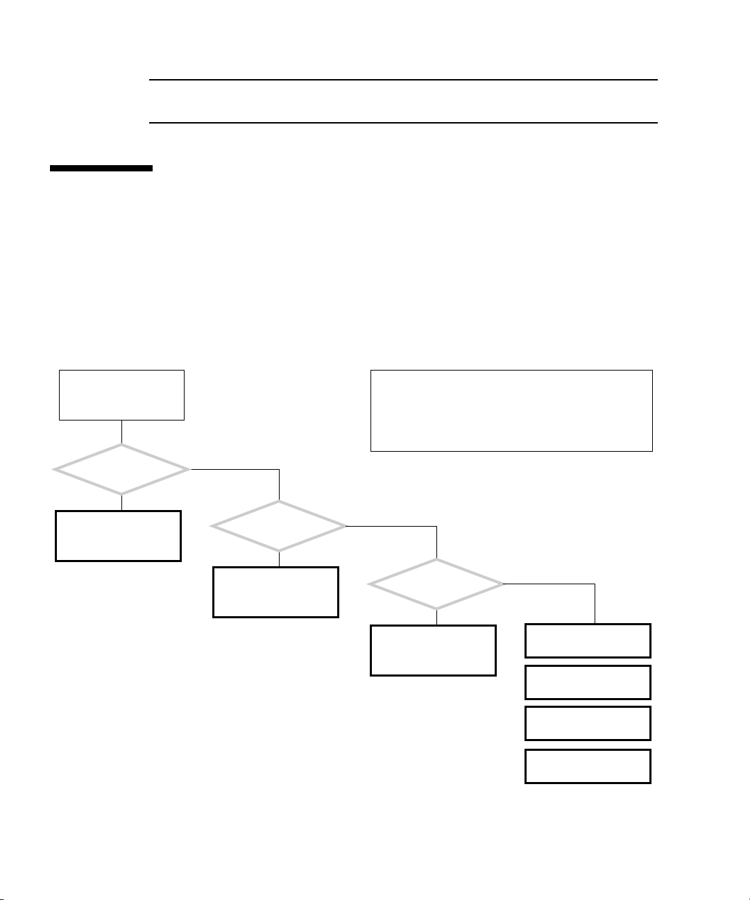
1.3 How to Use This Manual
When you service the Sun Blade 1500 workstation, begin with the Start Here
flowchart,
■ Troubleshooting
■ Component removal, installation, and verification
■ Workstation customization
■ Product information
START HERE
Is something wrong
with the system?
Y
See “Basic Troubleshoot-
ing” on page 3-1.
FIGURE 1-1. The Start Here flowchart links you to information about:
The start here flowchart helps you identify what section of
this book to read first. Boxes like this one appear at the
start of each flowchart and describe the normal operation
of the Sun Blade 1500 workstation. This box might also
have information to help clarify the flowchart or resolve
the problem.
N
Do you want to replace
a component?
Y
See “Preparing to
Replace Components” on
page 10-1.
N
Do you want
to add a component or
optional component?
Y
See “Customizing Your
System” on page 16-1.
N
See “Product Specifica-
tions” on page A-1.
FIGURE 1-1 Start Here Flowchart
1-4 Sun Blade 1500 Service, Diagnostics, and Troubleshooting Manual • December 2004
See “Signal Descrip-
tions” on page B-1.
See “Functional Descrip-
tion” on page C-1.
See “Power Manage-
ment” on page D-1.
Page 45

CHAPTER
2
Product Description
Topics covered in this chapter are:
■ “Product Overview” on page 2-1
■ “External System Description” on page 2-3
■ “Replaceable Components” on page 2-7
■ “Supported Sun Monitors” on page 2-10
2.1 Product Overview
The Sun Blade 1500 workstation has the power and expandability to handle a wide
range of tasks. Examples of these tasks range from entry-level 2D graphics EDA
applications to mid-range 3D graphics MCAD applications. Combined with the
power of the Solaris operating system, Sun Blade 1500 workstation offers reliability
and scalability to match the power of its UltraSPARC IIIi.
The Sun Blade 1500 workstation provides the following features in the base
configuration:
■ UltraSPARC IIIi 1.5 GHz 64-bit processor
■ 1 GB of DDR1 memory
■ Sun XVR-100 graphics accelerator
■ 120 GB ATA 100 hard drive
■ High-speed optical drive
2-1
Page 46

The Sun Blade 1500 workstation is configured with the features described in
TABLE 2-1.
TABLE 2-1 Sun Blade 1500 Configured Features
Feature Description
Processor 1.5 GHz UltraSPARC IIIi CPU with 1 MB integrated
Level2 cache, heat sink, and fan
Operating system Preinstalled Solaris 8 2/04 and Solaris 9 9/04
operating system supporting 32 and 64-bit
applications
Enclosure Deskside system enclosure with front-panel access
to optical media drive and smart card reader
Memory options From a minimum of 1 GB to a maximum of 8 GB of
ECC error-correcting DDR-1 SDRAM memory,
using matched pairs of 512 MB, 1 GB, or 2 GB
DIMMs
Maximum of 2 DIMM pairs per system (4 DIMMS
total)
Power supply 420 W autoranging
Internal storage One or two 120 GB ATA 100 3.5-inch hard drives
(7,200 rpm)
Note: Internal drive mirroring is not supported.
Optical media DVD/CD-RW drive
Audio CD-quality audio
Controlled system
access
Graphics accelerator PCI-based graphics accelerators
Keyboard Sun Type-6 USB AT 101 layout
Mouse Sun 3-button Crossbow USB mouse
Expansion slots on the
motherboard
Smart card reader
•Sun XVR-100 - up to 3
•Sun XVR-600 - up to 2
•Sun XVR-1200 - one
Peripheral component interconnect (PCI) slots:
1 64-bit at 66 MHz connector (slot 4)
2 64-bit at 33 MHz connectors (slots 2 and 3)
2 32-bit at 33 MHz connectors (slots 0 and 1)
2-2 Sun Blade 1500 Service, Diagnostics, and Troubleshooting Manual • December 2004
Page 47

TABLE 2-1 Sun Blade 1500 Configured Features (Continued)
Feature Description
Rear panel connectors
for external options
2 universal serial bus (USB) 1.1 connectors
2 serial connectors (DB-9)
1 parallel connector (DB-25)
1 twisted-pair Ethernet (TPE) 10/100/1000BASE-T
connector (RJ-45)
1 audio line-in connector
1 audio line-out connector
1394/USB card: 2 IEEE 1394A connectors and 3
universal serial bus (USB) 2.0 connectors
Front panel connectors
for external options
2 USB 1.1 connectors
1 headphone connector
1 microphone connector
Note – Some diskless Sun Blade 1500 workstations are configured without a hard
drive or optical drive.
Note – If you have a plastic rivet in the headphone jack of the optical drive, do not
remove the rivet. Instead, use the headphone jack at the bottom of the front panel.
The Sun Blade 1500 workstation also supports the following options:
■ Second hard drive
■ PCI SCSI host bus adapters
■ PCI serial communications adapters
■ PCI network adapters
■ PCI Fibre Channel adapters
■ SunPCi III Pro coprocessor cards
■ Sun StorEdge™ A1000, A5x00, and D1000 hard drive arrays
■ Sun StorEdge L1000 and L11000 tape drive arrays
2.2 External System Description
FIGURE 2-1, FIGURE 2-2, and FIGURE 2-3 identify external components and connectors
of the Sun Blade 1500 workstation.
Chapter 2 Product Description 2-3
Page 48

FIGURE 2-1 Monitor, Keyboard, Mouse, and Sun Blade 1500 Workstation
Note – Make sure that the keyboard and mouse are only connected to USB 1.1
compliant connectors on the bezel or rear panel. See
“Rear Panel Overview, Sun
Blade 1500 Workstation” on page 2-6.
2-4 Sun Blade 1500 Service, Diagnostics, and Troubleshooting Manual • December 2004
Page 49

1
2
3
4
5
6
789
FIGURE 2-2 Bezel Overview, Sun Blade 1500 Workstation
TABLE 2-2 Bezel Overview, Sun Blade 1500 Workstation
Callout in
FIGURE 2-2 Part Description Bezel Symbol
1 Smart card reader LED none
2 Smart card reader none
3 Optical drive none
4 Optical drive status LED none
5 Optical drive eject button
Chapter 2 Product Description 2-5
Page 50

TABLE 2-2 Bezel Overview, Sun Blade 1500 Workstation (Continued)
Callout in
FIGURE 2-2 Part Description Bezel Symbol
6 Power button with LED
7 USB v1.1 connector (2)
8 Audio connector, headphone
9 Audio connector, microphone
A
B
C
D
E
F
G
H
I
K
L
J
FIGURE 2-3 Rear Panel Overview, Sun Blade 1500 Workstation
2-6 Sun Blade 1500 Service, Diagnostics, and Troubleshooting Manual • December 2004
Page 51

TABLE 2-3 Rear Panel Overview, Sun Blade 1500 Workstation
Callout in
FIGURE 2-3 Part Description Rear Panel Symbol
A Power connector none
B USB v1.1 connector (2)
C Serial1 connector (DB-9)
D Parallel connector (DB-25)
E Serial2 connector (DB-9)
F Twisted-pair Ethernet (TPE)
G Audio connector, line-out
H Audio connector, line-in
I Graphics accelerator
J IEEE 1394/USB v2.x combination
card with 2 IEEE 1394a connectors
and 3 USB v2.0 ports
K PCI card connector (66 MHz): PCI
connector 4
L PCI card connectors (33 MHz): PCI
connector 0, PCI connector 1, PCI
connector 2, and PCI connector 3
1
2
PCI 4
66
PCI 3
PCI 2
PCI 1
PCI 0
Note – The combination card connectors for your Sun Blade 1500 workstation might
be reversed when compared with FIGURE 2-3. Their function is the same.
2.3 Replaceable Components
FIGURE 2-4 shows the replaceable components of the Sun Blade 1500 workstation.
Chapter 2 Product Description 2-7
Page 52

4
7
6
2
10
3
13
8
14
9
15
5
12
1
11
FIGURE 2-4 Exploded Diagram of Sun Blade 1500 Replaceable Components
More information about the replaceable components is listed in TABLE 2-4.
TABLE 2-4 Sun Blade 1500 Replaceable Components
Callout in
FIGURE 2-4 Component Description
1 Hard drive Hard drive, 120 GB, ATA 100/IDE
2 Optical drive DVD/CD-RW
2-8 Sun Blade 1500 Service, Diagnostics, and Troubleshooting Manual • December 2004
Page 53

TABLE 2-4 Sun Blade 1500 Replaceable Components (Continued)
Callout in
FIGURE 2-4 Component Description
3 DIMM (512 MB)
DIMM (1 GB)
DIMM (2 GB)
4 Power supply Power Supply, 420 W, 100 - 240 VAC
5 Front fan Front fan, Sun Blade 1500 chassis,
6 Rear fan Rear fan, Sun Blade 1500 chassis,
7 Smart card reader Smart card reader, bare board
8 Audio USB board USB connector board, mounting bracket
9 CPU fan and heat sink assembly Heat sink, integrated fan, 12VDC
10 Graphics accelerator Sun XVR-600 PCI graphics card
11 Combination card IEEE 1394/USB 2.0 I/O PCI card
12 Speaker assembly Speaker, 8 ohms
13 Power switch and cable kit Cable kit, Sun Blade 1500 chassis
14 Motherboard Sun Blade 1500 motherboard
15 Lithium battery Type CR2032
DIMM, 512 MB, DDR1, ECC
DIMM, 1 GB, DDR1, ECC
DIMM, 2 GB, DDR1, ECC
12VDC
12VDC
Sun XVR-100 PCI graphics card
Sun XVR-1200 PCI graphics card
Contact your Sun Microsystems service representative if you need a component.
Note – The components listed in TABLE 2-4 are subject to change without notice.
Consult your authorized Sun sales representative or service provider to confirm a
part number prior to ordering a replacement component, or search:
http://www.sun.com/ibb/spares
Chapter 2 Product Description 2-9
Page 54

2.4 Supported Sun Monitors
The Sun Blade 1500 workstation supports the monitors listed in TABLE 2-5. The Sun
XVR-100 and Sun XVR-1200 graphics accelerators can be configured to support
multiple displays.
TABLE 2-5 Monitors supported by the Sun Blade 1500 Workstation
Number of monitors supported
Monitor Maximum resolution Sun XVR-100 Sun XVR-600 Sun XVR-1200
17-inch color 1152 x 900 @ 66 Hz Up to 2 1 Up to 2
19-inch LCD color 1280 x 1024 @ 60/76 Hz Up to 2 1 Up to 2
22-inch CRT color 1600 x 1200 @ 75 Hz Up to 2 1 Up to 2
24.1-inch LCD flat screen color 1920 x 1200 @ 60 Hz Up to 2 1 Up to 2
Dual monitor support requires special cabling and software configuration. For more
information about the Sun XVR-100, Sun XVR-600, and Sun XVR-1200 graphics
accelerators, refer to the Sun XVR-100 Graphics Accelerator Installation Guide, 8167560, the
the Sun XVR-1200 Graphics Accelerator Installation and User’s Guide, 816-7386.
Sun XVR-600 Graphics Accelerator Installation and User’s Guide, 817-2195, or
2-10 Sun Blade 1500 Service, Diagnostics, and Troubleshooting Manual • December 2004
Page 55

CHAPTER
3
Basic Troubleshooting
This chapter provides basic troubleshooting assistance. Topics include:
■ “Power-On Sequence” on page 3-1
■ “Display and Audio Responses” on page 3-2
■ “Troubleshooting Commands” on page 3-15
3.1 Power-On Sequence
When you power on the Sun Blade 1500 workstation, a series of tasks and processes
brings the workstation to a user-ready state.
The following lists the sequence of power-on events that occur before a user can
interact with the Sun Blade 1500 workstation.
1. Power button is pressed.
2. OpenBoot PROM initiates system power-on reset (SPOR).
3. OpenBoot PROM initiates power-on self-test (POST) (if enabled).
4. OpenBoot PROM loads device drivers.
5. OpenBoot PROM loads workstation configuration from NVRAM.
6. OpenBoot PROM initializes bus and PCI card self-test diagnostics.
7. OpenBoot PROM loads and executes boot block.
8. Boot block loads and executes bootstrap program.
9. Bootstrap loads Solaris kernel.
10. Bus connections and hardware components are probed.
3-1
Page 56
11. init program is loaded and executed.
12. init program reads /etc/inittab.
13. init program launches rc scripts, which read, check, and mount file systems.
14. /etc/vfstab file system is checked and mounted.
15. Additional rc script files are executed.
If the power-on behavior seems erratic, see “Power-On Flowchart” on page 4-3
3.2 Display and Audio Responses
Component failures can often be diagnosed by looking at the monitor or listening to
the system. Topics in this section include:
■ “Displayed Screens” on page 3-2
■ “Displayed Messages” on page 3-5
■ “Audio Responses” on page 3-12
3.2.1 Displayed Screens
TABLE 3-1 describes what you might see on the monitor, what the images mean, and
where to find assistance in this manual to resolve the problem.
TABLE 3-1 Screen Images and What They Mean
Screen Images Description Meaning Comment
White screen with
banner and text.
Error message
displayed.
3-2 Sun Blade 1500 Service, Diagnostics, and Troubleshooting Manual • December 2004
Error from
OpenBoot PROM.
Error from Solaris
operating system.
See “OpenBoot PROM
Messages” on page 3-6.
See “Solaris Error Messages” on
page 3-8.
Page 57

TABLE 3-1 Screen Images and What They Mean (Continued)
Screen Images Description Meaning Comment
White screen with
banner and text.
Information
displayed in banner
is incorrect.
Display has
flickering horizontal
lines.
GUI is too small,
too large, or not
centered.
Corruption of
OpenBoot PROM.
Corruption of
NVRAM.
Monitor sync
problem.
Monitor settings
or sync problem.
See “OpenBoot PROM
Messages” on page 3-6.
See “NVRAM Problem” on
page 4-39.
Verify monitor can sync to set
frequency. See
“Graphics
Accelerators” on page C-21. Also
see monitor documentation.
See “Monitor Problem” on
page 4-14.
See “PCI Card Problem” on
page 4-28.
Adjust monitor according to
monitor manual.
Verify monitor can sync to set
frequency. See
“Graphics
Accelerators” on page C-21.
See “Monitor Problem” on
page 4-14.
White bar with
black text across
GUI.
Error message in
terminal window.
Error occurred in
Solaris kernel.
Error occurred in
process started
from that terminal.
See “Other Messages” on
page 3-11.
See “Solaris Error Messages” on
page 3-8.
See “Other Messages” on
page 3-11.
See “Graphical User Interface
Problem” on page 4-22.
Chapter 3 Basic Troubleshooting 3-3
Page 58

TABLE 3-1 Screen Images and What They Mean (Continued)
Screen Images Description Meaning Comment
Ψ∆
ΣΦΞ
GUI colors flash or
are wrong.
GUI has artifacts. Graphics
GUI is in wrong
language.
Color registers
exhausted.
Monitor problem. See “Monitor Problem” on
accelerator
problem.
Locale problem. 1. Log out.
Allocate more colors to GUI. See
“Avoiding Colormap Flash” on
page 11-3 7.
page 4-14.
See “PCI Card Problem” on
page 4-28.
2. At the login GUI Options
pulldown, select Language.
3. Select your language.
4. Log in as usual.
Window in GUI is
completely white.
Display is all one
color.
3-4 Sun Blade 1500 Service, Diagnostics, and Troubleshooting Manual • December 2004
Window process is
hung.
Monitor problem. See “Monitor Problem” on
Graphics
accelerator
problem.
NVRAM problem. See “NVRAM Problem” on
See “Graphical User Interface
Problem” on page 4-22.
page 4-14.
See “PCI Card Problem” on
page 4-28.
page 4-39.
Page 59

TABLE 3-1 Screen Images and What They Mean (Continued)
Screen Images Description Meaning Comment
Display is black
with hourglass.
Display is black
with mouse pointer.
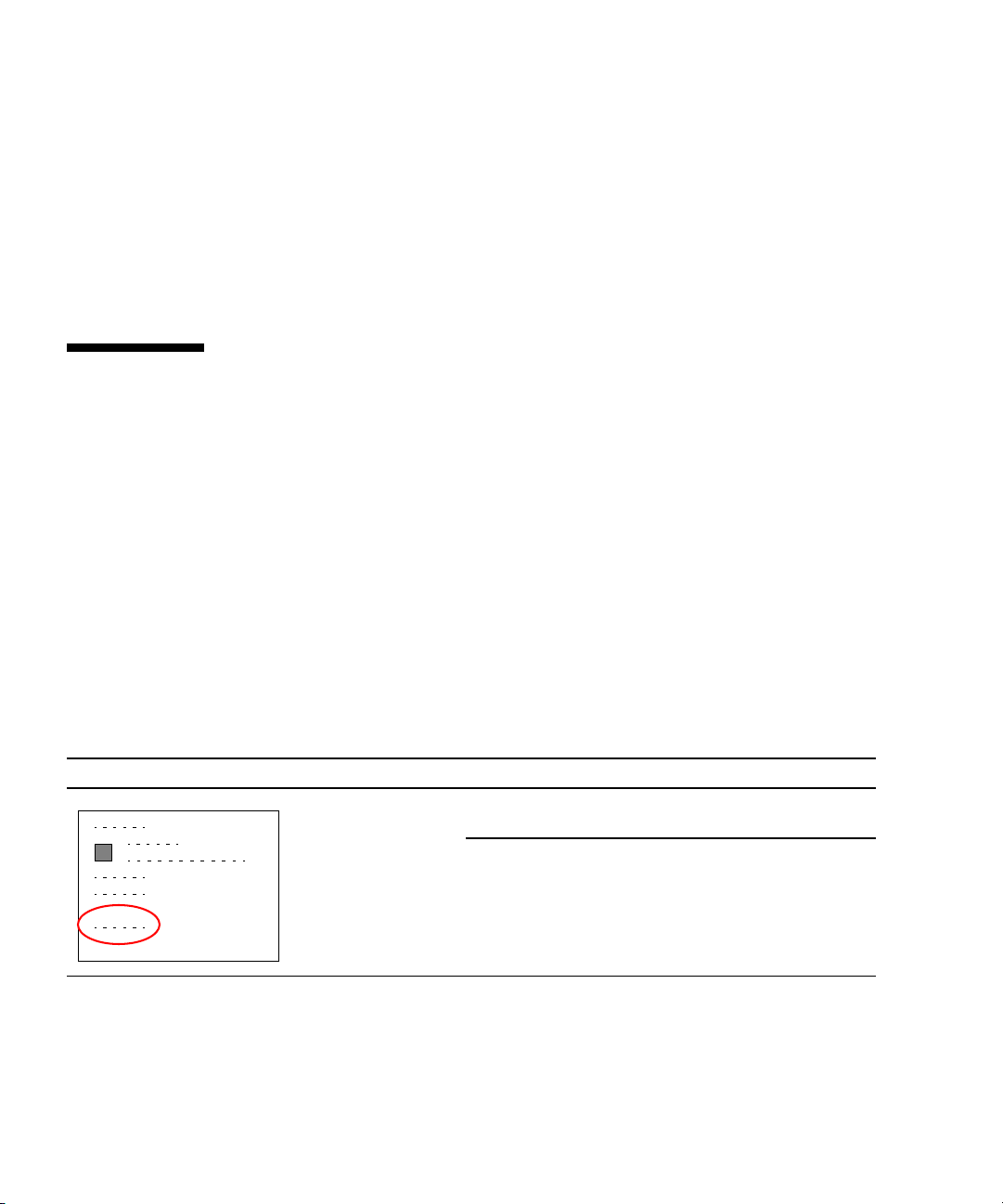
3.2.2 Displayed Messages
When a failure occurs, a message might be displayed on the system’s monitor. Use
the following flowchart to determine which message table addresses the error
message you see.
Network problem. See “Network Problem” on
page 4-17.
Dtlogin problem. See “Login Problem” on
page 4-20.
Network problem. See “Network Problem” on
page 4-17.
Dtlogin problem. See “Login Problem” on
page 4-20.
Chapter 3 Basic Troubleshooting 3-5
Page 60

An error message is displayed on the system’s
monitor.
Use this flowchart to determine which message table to
look up the error message you see. If the message is not
provided in any table, consult with a system administrator.
Was the Solaris operating
system running?
Y
Was the message
displayed in a white band
with black text across the
GUI?
Y
See “Other Messages” on
page 3-11.
FIGURE 3-1 Displayed Messages Flowchart
N
Is the screen all white
with black text?
See “OpenBoot PROM
Messages” on page 3-6.
N
See “Solaris Error Mes-
sages” on page 3-8.
3.2.2.1 OpenBoot PROM Messages
N
Y
See “Displayed Screens”
on page 3-2.
TABLE 3-2 lists some common fault messages or portions of fault messages displayed
by the OpenBoot PROM, their meanings, and what to do next.
TABLE 3-2 OpenBoot PROM Messages and Their Meaning
Message Meaning What to Do
The date is displayed as:
01/01/2000 00:00:00 GMT
3-6 Sun Blade 1500 Service, Diagnostics, and Troubleshooting Manual • December 2004
The battery has drained. Replace the battery. See
“Replacing the Battery” on
page 11-2 2.
Page 61

TABLE 3-2 OpenBoot PROM Messages and Their Meaning (Continued)
Message Meaning What to Do
Can’t open boot device
Can’t run OBDIAG from the
device tree node or with the
active instance
NOTICE - CPUx Banky DIMMs are
from different vendors.
NOTICE - CPUx Banky DIMMs have
different architectures and
will not be used.
Searching for self-test methods
. . . Rejecting alloc-mem!
Starting xv-500 self-test
The process “cs00.sh” has been
exited with retcode#256
Timeout waiting for ARP/RARP
packet
/usr/bin/ps/getexecname () has
failed
The device specified for
boot is unavailable.
Attempt to run OpenBoot
Diagnostics from a selected
device node.
A pair of DIMMs are each
from different
manufacturers.
A pair of DIMMs are each
of different architectures.
The DIMMs are not used.
OpenBoot Diagnostics
failed to start. Some devices
might be tied to other
processes.
Sun XVR-1200 PROM error. Type:
The battery has drained. Replace the battery. See
Network connection
problem.
The battery has drained. Replace the battery. See
• For hard drive, check
internal connections. Drive
might be corrupted. See
“Hard Drive Problem” on
page 4-8.
• For optical drive, check that
disc is bootable. Check
internal connections. See
“Optical Drive Problem” on
page 4-25.
• For network, check network
connections. Check boot
server. See “Network
Problem” on page 4-17.
Type:
ok unselect-dev
Install DIMMs in identical
pairs. See
DIMMs” on page 11-2.
Install DIMMs in identical
pairs. See
DIMMs” on page 11-2.
Type:
“Replacing the
“Replacing the
ok unselect-dev
ok show-devs
search for the text: xvr-1200
“Replacing the Battery” on
page 11-2 2.
Check network connection.
“Network Problem” on
See
page 4-17.
“Replacing the Battery” on
page 11-2 2.
Chapter 3 Basic Troubleshooting 3-7
Page 62

TABLE 3-2 OpenBoot PROM Messages and Their Meaning (Continued)
Message Meaning What to Do
WARNING: Timed out waiting for
NIS to come up
The name service cannot be
found.
Check network connection.
“Network Problem” on
See
page 4-17. Check system name
service configuration
information.
3.2.2.2 Solaris Error Messages
TABLE 3-3 lists some common error messages or portions of error messages displayed
while the Solaris operating system is functioning, their meanings, and what to do
next. These messages are high-level and might be related to software, rather than
hardware failure.
TABLE 3-3 Solaris Error Messages and Their Meanings
Message Meaning What to do
Arguments too long
automountd[int]:
server
hostname
responding
Bad address
Bad file number
BAD TRAP
Broken pipe
Bus error
Command not found
Connection closed
(by foreign host)
Too many arguments follow a C shell
command.
An NFS server cannot be mounted. Check the NFS server’s status
The value of an address is invalid. Determine and use the correct
A program error where the application does
not have permission to interact with the file.
Faulty hardware or mismatch of hardware and
its configuration. Can sometimes indicate a
bad or earlier version CPU. Usually precedes a
panic.
Occurs when a pipe (|) directs without data. Check the structure of the
I/O was attempted on a nonexistent device.
Might be caused by invalid file descriptors,
bad memory allocation, or corrupt boot blocks.
The C shell could not find the command you
typed.
Timeout has occurred or network connection
failed from remote host using either
telnet.
or
rlogin
Run the command in the
Bourne shell.
and network connection.
address.
Program bug, or change
permissions of the file.
Check configuration. Check
hardware functionality.
command.
Check for device and its
connection.
Check the command path.
Type the command explicitly.
Try again. Check network
connection.
3-8 Sun Blade 1500 Service, Diagnostics, and Troubleshooting Manual • December 2004
Page 63

TABLE 3-3 Solaris Error Messages and Their Meanings (Continued)
Message Meaning What to do
Connection refused
Connection reset by
peer
Device busy
Error Host Unknown
Exec format error
File descriptor in
bad state
File exists
File name too long
giving up
Illegal Instruction
Illegal seek
INIT: Cannot create
/var/adm/utmpx
Invalid argument
Remote host actively refused connection or
network security policy was violated.
Connection timed out. Try again.
Device is already mounted or there was an
attempt to unmount a device while a file was
in use. Typically seen when ejecting an optical
media disc.
Name services have not been set up correctly
or an alias is missing from NS maps.
Software is not compatible with platform. File
is not an executable, though identified as such.
Permissions on file prevent reading. Check and reset file
An attempt to overwrite a file occurred. Rename or remove the
A file name was greater than 256 characters, or
a path name was over 1024 characters.
Try issuing xhost + on the
local host.
Close all files and quit all
applications from that mount
point. If it is an optical media
disc, stop the volume
manager.
Reconfigure name services or
update NS maps.
Check that the Binary
Compatibility Package is
installed. Check that the file is
truly executable.
permissions.
existing file.
If more characters are
required, edit the
/usr/include/limits.
file.
h
An action has been retried until it has timed
out. Can occur when syncing SCSI hard drive
file systems.
Application for a different platform was run,
there is too little swap space available, or a
data file was run as an executable.
Misuse of the pipe (|). Direct the output to a file, then
The root file system has been mounted as read
only, or has become corrupted.
An invalid parameter was specified that the
system cannot interpret.
Check cabling to suspect
hardware. Check hardware
driver.
Verify the compatibility of the
software. Check swap space.
Set correct permissions for the
file.
use the file as input.
Run fsck on the root file
system. If unsuccessful,
replace the root file system.
Check that the actions you are
taking make logical sense. For
example, don’t mount a
nonexistent file system.
Chapter 3 Basic Troubleshooting 3-9
Page 64

TABLE 3-3 Solaris Error Messages and Their Meanings (Continued)
Message Meaning What to do
Invalid null
command
I/O error
process killed
ld.so.1
No carrier
Network is down
Network is
unreachable
NFS read failed for
server
NFS server not
responding still
trying
No child process
No default media
available
No such device
No utmpx entry
Typographical error when using the pipe (|).
For example, a double pipe or no command
following a pipe.
Hardware error has occurred on storage
device.
Swap space is too small or stack size is too
large.
Runtime linker could not find file or symbol.
Swap space has been diminished by rogue
program. Memory leak.
Network connection faulty. Check network connection.
Network connection faulty. Check network connection.
There is no route to network, or gateways are
refusing packets.
File-sharing permissions changed while the
file was open.
NFS server is down or slow to respond. NFS
server network connection might be down.
Application is trying to communicate with
subprocess that does not exist.
No removable media exists or volume
manager is confused.
Check the format of the
command.
Check device media. If a hard
drive, run
Check swap space. Set stack
size to 8192.
Check for missing file. Reboot
system.
See
page 4-17.
See
page 4-17.
Check network security.
Close the file and reset the
permissions.
Check resource load and
network connection of NFS
server.
Restart the parent process.
Insert media or update the
volume manager with the
fsck.
“Network Problem” on
“Network Problem” on
volcheck command.
Device does not exist. Check hardware connections
of suspect device.
File system is full. In single-user mode, zero-out
/var/adm/utmp and
the
/var/adm/utmpx files.
Bring system up and clean out
large files starting in the
directory.
/var
3-10 Sun Blade 1500 Service, Diagnostics, and Troubleshooting Manual • December 2004
Page 65

TABLE 3-3 Solaris Error Messages and Their Meanings (Continued)
Message Meaning What to do
Not on system
console
Package not
Security is set so that superuser logins occur
only at the console.
A software package is missing. Install the package.
installed
RPC: program not
Corruption of the rpc.bynumber NIS map. Check the rpc.bynumber
registered
Segmentation fault
Stale NFS file
handle
A programming error. The command file core
A file or directory opened by a NFS client was
removed from or permissions changed on the
NFS server.
3.2.2.3 Other Messages
TABLE 3-4 lists portions of fault messages that might also be displayed while the
Solaris software is functioning, their meanings, and what to do next. These messages
are mostly related to hardware failures.
TABLE 3-4 Other Messages and Their Meaning
Comment out the CONSOLE
line in the
/etc/default/login
file. This action compromises
security.
NIS map.
returns the application that
caused the fault.
Reboot the NFS client.
Message Meaning What to do
Panic in kernel
xntpd[356]: too many recvbufs
allocated (30)
metainit:hostname: there are no
existing databases
WARNING: timeout: reset target
chno = 0 targ = 0
WARNING: timeout: reset bus
The Solaris kernel can no
longer continue to run.
Usually precedes a core
dump.
Problem with network time
protocol daemon.
The Solstice Disk Suite
software is installed, but
not configured.
Hard drive is not
responding to resets. For
this example, it is HDD0.
Message might identify
hardware that is at fault.
Check memory. See
Problem” on page 4-37.
Check network. See “Network
Problem” on page 4-17. Check
time server. Contact system
administrator.
Not a problem. Message can
be ignored.
Check hard drive and
connections. See
Problem” on page 4-8.
chno = 0 targ = 0
Chapter 3 Basic Troubleshooting 3-11
“Memory
“Hard Drive
Page 66

TABLE 3-4 Other Messages and Their Meaning (Continued)
Message Meaning What to do
Bad magic number in disk label
Can’t open disk label package
starting rpc services: rpcbin
keyserv
The X-server can not be started
on display :0 ...
WARNING: fcsm: _init: Transport
Layer driver ’fp’ load failed
Partitions are corrupted on
hard drive.
Network problem if system
does not boot and message
persists.
The GUI cannot be started
for certain software
components are not
configured properly
Might appear in
/var/adm/messages.
Repartition and format hard
drive. Refer to Solaris
documentation.
Check network. See “Network
Problem” on page 4-17. Check
time server.
Attach a mouse to the rear
panel USB connectors. Check
mouse and connection.
Not a problem. Message can
be ignored.
3.2.3 Audio Responses
TABLE 3-5 describes what sounds you might hear from different areas of the system,
what the sounds mean, and where to find assistance in this manual to resolve the
problem.
TABLE 3-5 System Sounds at Locations and What They Mean
Location Sound Meaning Comment
System Silence Power delivery problem. See “Power Problem”
on page 4-6.
3-12 Sun Blade 1500 Service, Diagnostics, and Troubleshooting Manual • December 2004
Page 67

TABLE 3-5 System Sounds at Locations and What They Mean (Continued)
Location Sound Meaning Comment
Monitor Ticking Monitor is searching for
video mode or trying to sync.
Very high-pitched whine Monitor cannot sync. Change graphics
Monitor or power
Low-pitched buzz Power supply degraded. Replace the power
supply
Monitor power supply
degraded.
Verify monitor can sync
to set frequency. See
“Graphics
Accelerators” on
page C-21. Also see
monitor
documentation.
See “Monitor Problem”
on page 4-14.
See “PCI Card
Problem” on page 4-28.
accelerator resolution.
See graphics
accelerator
documentation.
See “Monitor Problem”
on page 4-14.
See “PCI Card
Problem” on page 4-28.
supply. See
“Replacing
the Power Supply” on
page 13-2.
Replace the monitor.
Chapter 3 Basic Troubleshooting 3-13
Page 68

TABLE 3-5 System Sounds at Locations and What They Mean (Continued)
Location Sound Meaning Comment
Front of system
chassis
Front or rear of
system chassis
Upon power on, three
beeps and the system
powers off
Invalid configuration.
Memory or CPU does not
match requirements.
See “Memory Problem”
on page 4-37 or
“Motherboard
Problem” on page 4-34.
Upon power on, four
beeps and the system
powers off
FRU ID checksum error. Replace motherboard.
“Replacing the
See
Motherboard” on
page 11-4 3.
Upon power on, five beeps
and the system powers off
Continuous beeping Keyboard key is stuck or
Internal reset failed. See “Motherboard
Problem” on page 4-34.
See “Keyboard
connection is bad.
Problem” on page 4-19.
Quiet scratching hard drive heads are moving. Hard drive is normal.
High-pitched humming hard drive bearings are
failing.
Replace the hard drive.
“Replacing a Hard
See
Drive” on page 12-2.
Low shrill sound Front fan bearing is failing. Replace front fan. See
“Replacing the Front
Fan” on page 13-8.
Rear fan bearing is failing. Replace rear fan. See
“Replacing the Rear
Fan” on page 13-15.
Power supply fan bearing is
failing.
Replace the power
supply. See
“Replacing
the Power Supply” on
page 13-2.
Quiet grumbling sound Temperature is such that fans
Fans are normal.
are barely turning.
Silence from fans Front fan is not spinning.
Rear fan is not spinning.
Power supply fan is not
spinning.
See “System Fan
Problem” on page 4-9.
See “Power Problem”
on page 4-6.
3-14 Sun Blade 1500 Service, Diagnostics, and Troubleshooting Manual • December 2004
Page 69

TABLE 3-5 System Sounds at Locations and What They Mean (Continued)
Location Sound Meaning Comment
Optical drive Repetitive quiet clunking Disc is unbalanced. Reposition disc.
Rapid shifting Laser pickup head is moving. Optical drive normal.
Rushing air that is
constant or intermittently
changes
Rushing air that is
rhythmically changing
Very high-pitched
squeaking
Disc is spinning properly. Optical drive normal.
Laser pickup head cannot
locate tracks on disc.
Laser pickup head is out of
alignment.
Try a different disc. If
the problem continues,
“Optical Drive
see
Problem” on page 4-25.
Try a different disc. If
the problem continues,
replace optical drive.
“Replacing the
See
Optical Drive” on
page 12-9.
3.3 Troubleshooting Commands
The section discusses superuser commands that assist in troubleshooting problems
with the Sun Blade 1500 workstation. Commands discussed are:
■ “iostat Command” on page 3-15
■ “prtdiag Command” on page 3-18
■ “prtconf Command” on page 3-20
■ “netstat Command” on page 3-23
■ “ping Command” on page 3-25
■ “ps Command” on page 3-27
■ “prstat Command” on page 3-29
Most of these commands are located in the /usr/bin or /usr/sbin directories.
3.3.1 iostat Command
The iostat command iteratively reports terminal, drive, and tape I/O activity, as
well as CPU utilization.
Chapter 3 Basic Troubleshooting 3-15
Page 70

3.3.1.1 Options
TABLE 3-6 describes options for the iostat command and how those options can
help troubleshoot the Sun Blade 1500 workstation.
TABLE 3-6 Options for iostat
Option Description How It Can Help
No option Reports status of local I/O devices. A quick three-line output of device
status.
-c
-e
-E
-n
-x
Reports the percentage of time the system has
spent in user mode, in system mode, waiting for
I/O, and idling.
Displays device error summary statistics. The
total errors, hard errors, soft errors, and transport
errors are displayed.
Displays all device error statistics. Provides information about devices:
Displays names in descriptive format. Descriptive format helps identify
For each drive, reports extended drive statistics.
The output is in tabular form.
Quick report of CPU status.
Provides a short table with accumulated
errors. Identifies suspect I/O devices.
manufacturer, model number, serial
number, size, and errors.
devices.
Similar to the -e option, but provides
rate information. This helps identify
poor performance of internal devices
and other I/O devices across the
network.
3.3.1.2 Examples
The following examples show output for the iostat command and its options.
# iostat
tty dad0 sd0 nfs1 nfs2 cpu
tin tout kps tps serv kps tps serv kps tps serv kps tps serv us sy wt id
0 5 128 15 6 0 0 0 0 0 0 50 3 9 2 8 4 86
# iostat -c
cpu
us sy wt id
2 7 4 87
3-16 Sun Blade 1500 Service, Diagnostics, and Troubleshooting Manual • December 2004
Page 71

# iostat -e
---- errors --device s/w h/w trn tot
dad0 0 0 0 0
sd0 0 2 0 2
nfs1 0 0 0 0
nfs2 0 0 0 0
nfs3 0 0 0 0
nfs4 0 0 0 0
nfs5 0 0 0 0
# iostat -x
extended device statistics
device r/s w/s kr/s kw/s wait actv svc_t %w %b
dad0 12.3 0.9 106.6 3.7 0.0 0.1 5.9 1 4
sd0 0.0 0.0 0.0 0.0 0.0 0.0 0.0 0 0
nfs1 0.0 0.0 0.0 0.0 0.0 0.0 0.0 0 0
nfs2 1.2 1.1 20.9 21.2 0.0 0.0 9.3 0 2
nfs3 0.2 0.0 0.9 0.0 0.0 0.0 2.5 0 0
nfs4 0.0 0.0 0.0 0.0 0.0 0.0 0.0 0 0
nfs5 1.5 0.0 30.2 0.0 0.0 0.1 38.6 0 4
# iostat -En
c0t0d0 Soft Errors: 0 Hard Errors: 0 Transport Errors: 0
Model: ST3120026A Revision: 8.01 Serial No: 3JT4H4C2
Size: 120.03GB <120031641600 bytes>
Media Error: 0 Device Not Ready: 0 No Device: 0 Recoverable: 0
Illegal Request: 0
c0t2d0 Soft Errors: 0 Hard Errors: 0 Transport Errors: 0
Vendor: LITE-ON Product: COMBO SOHC-4832K Revision: O3K1
Serial No:
Size: 0.00GB <0 bytes>
Media Error: 0 Device Not Ready: 0 No Device: 0 Recoverable: 0
Illegal Request: 0 Predictive Failure Analysis: 0
Chapter 3 Basic Troubleshooting 3-17
Page 72

3.3.2 prtdiag Command
The prtdiag command displays configuration and diagnostic information for a
system. The diagnostic information identifies any failed component in the system.
The prtdiag command is located in the /usr/platform/platform-name/sbin/
directory.
Note – The prtdiag command might indicate a slot number different than that
identified elsewhere in this manual. This is normal.
3.3.2.1 Options
TABLE 3-7 describes options for the prtdiag command and how those options can
help troubleshoot the Sun Blade 1500 workstation.
TABLE 3-7 Options for prtdiag
Option Description How It Can Help
No option Lists system components. Identifies CPU timing and PCI cards installed.
-v
Verbose mode. Displays the
time of the most recent AC
power failure, the most recent
hardware fatal error
information, and (if applicable)
environmental status.
Provides the same information as no option. Additionally
lists fan status, temperatures, ASIC, and PROM revisions.
3.3.2.2 Examples
The following examples show output for the prtdiag command and its options.
3-18 Sun Blade 1500 Service, Diagnostics, and Troubleshooting Manual • December 2004
Page 73

# /usr/platform/sun4u/sbin/prtdiag
System Configuration: Sun Microsystems sun4u Sun Blade 1500 workstation
System clock frequency: 160 MHZ
Memory size: 1GB
==================================== CPUs ====================================
E$ CPU CPU Temperature
CPU Freq Size Implementation Mask Die Amb. Status Location
--- -------- ---------- ------------------- ----- ---- ---- ------ ------- 0 1500 MHz 1MB SUNW,UltraSPARC-IIIi 3.3 68C 30C online MB/0
================================= IO Devices =================================
Bus Freq Slot + Name +
Type MHz Status Path Model
---- ---- ---------- ---------------------------- -------------------pci 33 MB isa/su (serial)
okay /pci@1e,600000/isa@7/serial@0,3f8
pci 33 MB isa/su (serial)
okay /pci@1e,600000/isa@7/serial@0,2e8
.
.
.
pci 66 MB pci108e,1647 (network)
okay /pci@1f,700000/network@2
pci 66 MB/PCI4 SUNW,XVR-600 (display) SUNW,375-3153
okay /pci@1f,700000/SUNW,XVR-600@3
============================ Memory Configuration ============================
Segment Table:
----------------------------------------------------------------------Base Address Size Interleave Factor Contains
----------------------------------------------------------------------0x0 1GB 1 BankIDs 0
Bank Table:
---------------------------------------------------------- Physical Location
ID ControllerID GroupID Size Interleave Way
----------------------------------------------------------0 0 0 1GB 0
Memory Module Groups:
-------------------------------------------------ControllerID GroupID Labels Status
-------------------------------------------------0 0 MB/DIMM0
0 0 MB/DIMM1
=============================== usb Devices ===============================
Name Port#
------------ ----mouse 1
keyboard 2
Chapter 3 Basic Troubleshooting 3-19
Page 74

# /usr/platform/sun4u/sbin/prtdiag -v
System Configuration: Sun Microsystems sun4u Sun Blade 1500 workstation
System clock frequency: 160 MHZ
Memory size: 1GB
. . .
============================ Environmental Status ============================
Fan Speeds:
--------------------------------------------Location Sensor Status Speed
--------------------------------------------F2 CPU okay 3183rpm
F1 Intake okay 2280rpm
F0 Outtake okay 2280rpm
Temperature sensors:
----------------------------------------------------------------------------Location Sensor Temperature Lo LoWarn HiWarn Hi Status
----------------------------------------------------------------------------MB/0 Die 68C -10C 0C 95C 100C okay
MB Ambient 37C -10C 0C 70C 75C okay
MB Ambient 30C -11C 0C 60C 70C okay
================================ HW Revisions ================================
ASIC Revisions:
------------------------------------------------------------------Path Device Status Revision
------------------------------------------------------------------/pci@1e,600000 pci108e,a801 okay 4
/pci@1f,700000 pci108e,a801 okay 4
System PROM revisions:
---------------------OBP 4.16.3 2004/11/05 18:29 Sun Blade 1500 (Silver)
OBDIAG 4.16.3 2004/11/05 18:31
3.3.3 prtconf Command
Similar to the show-devs command run at the ok prompt, the prtconf command
displays the devices that are configured for the Sun Blade 1500 workstation.
The prtconf command identifies hardware that is recognized by the Solaris
operating system. If hardware is not suspected bad, yet software applications are
having trouble with the hardware, the
software recognizes the hardware, and if a driver for the hardware is loaded.
3-20 Sun Blade 1500 Service, Diagnostics, and Troubleshooting Manual • December 2004
prtconf command can indicate if the Solaris
Page 75

3.3.3.1 Options
TABLE 3-8 describes options for the prtconf command and how those options can
help troubleshoot the Sun Blade 1500 workstation.
TABLE 3-8 Options for prtconf
Option Description How It Can Help
No option Displays the device tree of
devices recognized by the
operating system.
-D
-p
-V
Similar to the output of no
option, however the device
driver is listed.
Similar to the output of no
option, yet is abbreviated.
Displays the version and date
of the OpenBoot PROM
firmware.
If a hardware device is recognized, then it is probably
functioning properly. If the message “
attached)
device, then the driver for the device is corrupt or missing.
Informs you of the driver needed or used by the operating
system to enable the device.
Does not report a “(driver not attached)”
message, only a quick view of the devices.
Provides a quick check of firmware version.
” is displayed for the device or for a sub-
(driver not
Chapter 3 Basic Troubleshooting 3-21
Page 76

3.3.3.2 Examples
The following examples show output for the prtconf command and its options.
# prtconf
System Configuration: Sun Microsystems sun4u
Memory size: 1024 Megabytes
System Peripherals (Software Nodes):
SUNW,Sun-Blade-1500
packages (driver not attached)
SUNW,builtin-drivers (driver not attached)
deblocker (driver not attached)
disk-label (driver not attached)
terminal-emulator (driver not attached)
dropins (driver not attached)
kbd-translator (driver not attached)
obp-tftp (driver not attached)
SUNW,i2c-ram-device (driver not attached)
SUNW,fru-device (driver not attached)
SUNW,asr (driver not attached)
ufs-file-system (driver not attached)
chosen (driver not attached)
openprom (driver not attached)
client-services (driver not attached)
options, instance #0
aliases (driver not attached)
. . .
3-22 Sun Blade 1500 Service, Diagnostics, and Troubleshooting Manual • December 2004
Page 77

# prtconf -D
System Configuration: Sun Microsystems sun4u
Memory size: 1024 Megabytes
System Peripherals (Software Nodes):
. . .
aliases
memory
virtual-memory
SUNW,UltraSPARC-IIIi, instance #0 (driver name: us)
memory-controller, instance #0 (driver name: mc-us3i)
pci, instance #0 (driver name: pcisch)
isa, instance #0 (driver name: ebus)
flashprom
rtc
i2c, instance #0 (driver name: pcf8584)
hardware-monitor, instance #0 (driver name: adm1031)
motherboard-fru-prom, instance #0 (driver name: seeprom)
dimm-spd, instance #1 (driver name: seeprom)
dimm-spd, instance #2 (driver name: seeprom)
clock-generator, instance #0 (driver name: ics951601)
. . .
3.3.4 netstat Command
The netstat command displays the network status.
3.3.4.1 Options
TABLE 3-9 describes options for the netstat command and how those options can
help troubleshoot the Sun Blade 1500 workstation.
TABLE 3-9 Options for netstat
Option Description How It Can Help
-i
Displays the interface state,
including packets in/out, error
in/out, collisions, and queue.
-i interval Providing a trailing number
with the
-i option repeats the
netstat command every
interval seconds.
-p
Displays the media table. Provides MAC address for hosts on the subnet.
Provides a quick overview of the system’s network status.
Helps identify intermittent or long duration network
events. By piping
activity can be viewed all at once.
netstat output to a file, overnight
Chapter 3 Basic Troubleshooting 3-23
Page 78

TABLE 3-9 Options for netstat (Continued)
Option Description How It Can Help
-r
-n
Displays the routing table. Provides routing information.
Replaces host names with IP
addresses.
When an address is more useful than a host name.
3.3.4.2 Examples
The following examples show output for the netstat command and its options.
# netstat -i 1
input bge0 output input (Total) output
packets errs packets errs colls packets errs packets errs colls
32703 0 23906 0 0 35527 0 26730 0 0
3 0 0 0 0 5 0 2 0 0
3 0 0 0 0 5 0 2 0 0
5 0 0 0 0 7 0 2 0 0
4 0 0 0 0 6 0 2 0 0
3 0 0 0 0 5 0 2 0 0
3 0 0 0 0 5 0 2 0 0
. . .
3-24 Sun Blade 1500 Service, Diagnostics, and Troubleshooting Manual • December 2004
Page 79

# netstat -p
Net to Media Table: IPv4
Device IP Address Mask Flags Phys Addr
------ -------------------- --------------- ----- --------------bge0 phatair-46 255.255.255.255 08:00:20:92:4a:47
bge0 ns-umpk27-02-46 255.255.255.255 08:00:20:93:fb:99
bge0 moreair-46 255.255.255.255 08:00:20:8a:e5:03
bge0 fermpk28a-46 255.255.255.255 00:00:0c:07:ac:2e
bge0 fermpk28as-46 255.255.255.255 00:50:e2:61:d8:00
bge0 kayakr 255.255.255.255 08:00:20:d1:83:c7
bge0 matlock 255.255.255.255 SP 00:03:ba:27:01:48
bge0 toronto2 255.255.255.255 08:00:20:b6:15:b5
bge0 tucknott 255.255.255.255 08:00:20:7c:f5:94
bge0 mpk28-lobby 255.255.255.255 08:00:20:a6:d5:c8
bge0 eggfooyoung 255.255.255.255 08:00:20:8d:6a:80
bge0 froggy 255.255.255.255 08:00:20:73:70:44
bge0 d-mpk28-46-245 255.255.255.255 00:10:60:24:0e:00
bge0 224.0.0.0 240.0.0.0 SM 01:00:5e:00:00:00
# netstat -r
Routing Table: IPv4
Destination Gateway Flags Ref Use Interface
-------------------- -------------------- ----- ----- ------ --------mpk28-046-n matlock U 1 6 bge0
224.0.0.0 matlock U 1 0 bge0
default fermpk28a-46 UG 1 22
localhost localhost UH 25 3018 lo0
3.3.5 ping Command
The ping command sends ICMP ECHO_REQUEST packets to network hosts.
Depending upon how the
identify troublesome network links or nodes. The destination host is specified in the
variable hostname.
ping command is configured, the output displayed can
Chapter 3 Basic Troubleshooting 3-25
Page 80

3.3.5.1 Options
TABLE 3-10 describes options for the ping command and how those options can help
troubleshoot the Sun Blade 1500 workstation.
TABLE 3-10 Options for ping
Option Description How It Can Help
hostname The probe packet is sent to
hostname and returned.
-g hostname Forces the probe packet to
route through a specified
gateway.
-i interface Designates which interface to
send and receive the probe
packet through.
-n
-s
-svR
Replaces host names with IP
addresses.
Ping continuously in one
second intervals. Ctrl-C aborts.
Upon abort, statistic are
displayed.
Displays the route the probe
packet followed in one second
intervals.
3.3.5.2 Examples
The following examples show output for the ping command and its options.
# ping -s teddybear
PING teddybear: 56 data bytes
64 bytes from teddybear (192.146.77.140): icmp_seq=0. time=1.
ms
64 bytes from teddybear (192.146.77.140): icmp_seq=1. time=0.
ms
64 bytes from teddybear (192.146.77.140): icmp_seq=2. time=0.
ms
^C
----teddybear PING Statistics---3 packets transmitted, 3 packets received, 0% packet loss
round-trip (ms) min/avg/max = 0/0/1
Verifies that a host is active on the network.
By identifying different routes to the target host, those
individual routes can be tested for quality.
Enables a simple check of secondary network interfaces.
Used when an address is more beneficial than a host name.
Helps identify intermittent or long-duration network
events. By piping
later viewed at once.
Indicates probe packet route and number of hops.
Comparing multiple routes can identify bottlenecks.
ping output to file, activity overnight is
3-26 Sun Blade 1500 Service, Diagnostics, and Troubleshooting Manual • December 2004
Page 81

# ping -svR teddybear
PING teddybear: 56 data bytes
64 bytes from teddybear (192.146.77.140): icmp_seq=0. time=2. ms
IP options: <record route> smuscampk27s02-r01 (192.146.5.123),
smuscampk14s19-r02-v516 (192.146.5.90), rmpk16a-077 (192.146.77.2),
teddybear (192.146.77.140), smuscampk16s02-r01 (192.146.5.83),
smuscampk11s10-r02-v827 (192.146.5.137), fermpk28ap-46 (192.146.46.2),
matlock (192.146.46.111), (End of record)
^C
----teddybear PING Statistics---1 packets transmitted, 1 packets received, 0% packet loss
round-trip (ms) min/avg/max = 2/2/2
3.3.6 ps Command
The ps command lists the status of system processes. Using options and rearranging
the command output can assist in determining the Sun Blade 1500 workstation
resource allocation.
3.3.6.1 Options
TABLE 3-11 describes options for the ps command and how those options can help
troubleshoot the Sun Blade 1500 workstation.
TABLE 3-11 Options for ps
Option Description How It Can Help
-e
-f
Displays information for every
process.
Generates a full listing. Provides the following process information: user ID, parent
-o option Allows configurable output.
pid, pcpu, pmem, and
The
comm options display process
ID, percent CPU consumption,
percent memory consumption,
and the responsible executable,
respectively.
Identifies the process ID and the executable.
process ID, system time when executed, and the path to
the executable.
Provides only most important information. Knowing the
percentage of resource consumption helps identify
processes that are affecting system performance and might
be hung.
Chapter 3 Basic Troubleshooting 3-27
Page 82

3.3.6.2 Examples
The following examples show output for the ps command and its options.
# ps -ef
UID PID PPID C STIME TTY TIME CMD
root 0 0 0 10:06:30 ? 0:18 sched
root 1 0 0 10:06:32 ? 0:00 /etc/init root 2 0 0 10:06:32 ? 0:00 pageout
root 3 0 0 10:06:32 ? 0:00 fsflush
root 100311 1 0 10:06:50 ? 0:00 /usr/lib/saf/sac -t 300
. . .
# ps -eo pcpu,pid,comm|sort -rn
1.4 100317 /usr/openwin/bin/Xsun
0.9 100460 dtwm
0.1 100677 ps
0.1 100600 ksh
0.1 100591 /usr/dt/bin/dtterm
0.1 100462 /usr/dt/bin/sdtperfmeter
0.1 100333 mibiisa
%CPU PID COMMAND
0.0 100652 /bin/csh
. . .
# ps -eo pmem,pid,comm|sort -rn
14.2 100317 /usr/openwin/bin/Xsun
4.4 100524 /net/dickens/fmsgml60/bin/sunxm.s5.sparc/makersgml
1.8 100460 dtwm
1.1 100591 /usr/dt/bin/dtterm
1.0 100650 /usr/dt/bin/dtterm
1.0 100494 /usr/dt/bin/dtterm
1.0 100462 /usr/dt/bin/sdtperfmeter
1.0 100453 /usr/dt/bin/dtsession
0.8 100452 /usr/dt/bin/ttsession
. . .
Note – When using sort with the -r option, the column headings are printed at the point
where the value in the first column is equal to zero.
3-28 Sun Blade 1500 Service, Diagnostics, and Troubleshooting Manual • December 2004
Page 83

3.3.7 prstat Command
The prstat utility iteratively examines all active processes on the system and
reports statistics based on the selected output mode and sort order. The
command provides output similar to the
3.3.7.1 Options
TABLE 3-12 describes options for the prstat command and how those options can
help troubleshoot the Sun Blade 1500 workstation.
TABLE 3-12 Options for prstat
Option Description How It Can Help
No option Displays a sorted list of the top
processes which are consuming
the most CPU resources. List is
limited to the height of the
terminal window and the total
number of processes. Output is
automatically updated every
five seconds. Ctrl-C aborts.
-n number Limits output to number of
lines.
-s key Permits sorting list by key
parameter.
-v
Verbose mode. Displays additional parameters.
Output identifies process ID, user ID, memory used, state,
CPU consumption, and command name. By default, list is
sorted by CPU consumption.
Limits amount of data displayed and identifies primary
resource consumers.
Useful keys are cpu (default), time, and size.
prstat
ps command.
Chapter 3 Basic Troubleshooting 3-29
Page 84

3.3.7.2 Examples
The following examples show output for the prstat command and its options.
# prstat
PID USERNAME SIZE RSS STATE PRI NICE TIME CPU PROCESS/NLWP
100688 root 1760K 1376K cpu0 59 0 0:00.00 0.1% prstat/1
100524 mm39236 28M 21M sleep 48 0 0:00.25 0.1% maker6X.exe/1
100317 root 28M 69M sleep 59 0 0:00.25 0.1% Xsun/1
100591 mm39236 7584K 5416K sleep 59 0 0:00.02 0.1% dtterm/1
100333 root 2448K 2152K sleep 58 0 0:00.00 0.0% mibiisa/12
100236 root 2232K 1832K sleep 58 0 0:00.00 0.0% lp/1
100600 root 1872K 1432K run 37 0 0:00.00 0.0% ksh/1
. . .
100403 mm39236 1832K 1368K sleep 59 0 0:00.00 0.0% csh/1
100311 root 1800K 1232K sleep 58 0 0:00.00 0.0% sac/1
Total: 65 processes, 159 lwps, load averages: 0.01, 0.02, 0.04
# prstat -n 5 -s size
PID USERNAME SIZE RSS STATE PRI NICE TIME CPU PROCESS/NLWP
100524 mm39236 28M 21M sleep 48 0 0:00.26 0.3% maker6X.exe/1
100317 root 28M 69M sleep 59 0 0:00.26 0.7% Xsun/1
100460 mm39236 11M 8760K sleep 59 0 0:00.03 0.0% dtwm/8
100453 mm39236 8664K 4928K sleep 48 0 0:00.00 0.0% dtsession/4
100591 mm39236 7616K 5448K sleep 49 0 0:00.02 0.1% dtterm/1
Total: 65 processes, 159 lwps, load averages: 0.03, 0.02, 0.04
# prstat -n 5 -v
PID USERNAME USR SYS TRP TFL DFL LCK SLP LAT VCX ICX SCL SIG PROCESS/NLWP
100692 root 31 62 - - - - 31 - 0 463 57K 0 prstat/1
100524 mm39236 0.6 0.3 - - - - 99 - 89 114 2K 0 maker6X.exe/1
100317 root 0.3 0.5 - - - - 99 - 288 45 2K 108 Xsun/1
100591 mm39236 0.1 0.0 - - - - 100 - 52 9 230 0 dtterm/1
100236 root 0.0 0.0 - - - - 100 - 5 0 52 0 lp/1
Total: 65 processes, 159 lwps, load averages: 0.02, 0.02, 0.03
3-30 Sun Blade 1500 Service, Diagnostics, and Troubleshooting Manual • December 2004
Page 85

CHAPTER
4
Troubleshooting Flowcharts
This chapter contains flowcharts to help you troubleshoot problems with your Sun
Blade 1500 workstation. The flowcharts are ordered parallel to the power-on
sequence. Flowchart topics covered are:
■ “Power-On Flowchart” on page 4-2
■ “Start Up Problems” on page 4-5
■ “Power Problem” on page 4-6
■ “Hard Drive Problem” on page 4-8
■ “System Fan Problem” on page 4-9
■ “USB Problem” on page 4-10
■ “Audio Output Problem” on page 4-12
■ “Monitor Problem” on page 4-14
■ “Network Problem” on page 4-17
■ “Keyboard Problem” on page 4-19
■ “Login Problem” on page 4-20
■ “Graphical User Interface Problem” on page 4-22
■ “Data Access and Running Applications Problems” on page 4-23
■ “Storage Problems” on page 4-24
■ “Optical Drive Problem” on page 4-25
■ “PCI Card Problem” on page 4-28
■ “IEEE 1394 Problem” on page 4-30
■ “Smart Card Reader Problem” on page 4-32
■ “Advanced Problems” on page 4-33
■ “Motherboard Problem” on page 4-34
■ “Memory Problem” on page 4-37
■ “NVRAM Problem” on page 4-39
■ “Battery Problem” on page 4-40
4-1
Page 86

4.1 Power-On Flowchart
The “Power-On Flowchart” on page 4-3 indicates points where proper startup can be
recognized. This flowchart helps identify what aspect of the Sun Blade 1500
workstation is at fault.
If you suspect a system failure, power on the system and follow the flowchart.
If you answer “No” to a question, direct your attention to the section provided or to
other flowchart cross-references.
If you complete the flowchart without answering “No” to any questions yet you still
suspect a failure with the Sun Blade 1500 workstation, see
Advanced Troubleshooting” on page 5-1 for more in-depth procedures.
“Introduction to
4-2 Sun Blade 1500 Service, Diagnostics, and Troubleshooting Manual • December 2004
Page 87

Press and release the
Power button.
Does the power supply
fan spin up?
Y
Does the hard
drive spin up?
Y
Does at least one of the
system fans spin up?
Y
N
N
N
Problem with fan. See
“System Fan Problem” on
page 4-9.
In normal operation, the system power-on sequence follows the path of Y for every question. Power on your system and follow this flowchart. Should your system resolve
to a N answer to a question, go to the cross-reference. If
several cross-references are listed, the first is the most
likely solution. Try the other cross-references if the first
does not resolve the problem.
Problem with power. See
“Power Problem” on
page 4-6.
Problem with hard drive.
See “Hard Drive Problem”
on page 4-8.
Does the speaker
beep only once?
Y
Is anything displayed
on the monitor?
Y
Can you log in
as your user?
Y
Go to
Next Page
FIGURE 4-1 Power-On Flowchart
N
N
N
Problem with monitor.
See “Monitor Problem”
on page 4-14.
Problem with log in. See
“Login Problem” on
page 4-20.
Problem with network.
See “Network Problem”
on page 4-17.
OR
OR
Problem with monitor.
See “Monitor Problem”
on page 4-14.
OR
Problem with graphics
accelerator. See “PCI Card
Problem” on page 4-28.
Problem with speaker.
See “Audio Output Prob-
lem” on page 4-12.
OR
Problem with memory or
motherboard. See “Audio
Responses” on page 3-12.
Chapter 4 Troubleshooting Flowcharts 4-3
Page 88

Next Page
Can you interact
with the GUI?
Y
Can you access data
and run applications?
Y
Can you use: the optical
drive, smart card reader,
PCI cards, USB, audio
ports?
Y
N
N
N
Problem with optical
drive. See “Optical Drive
Problem” on page 4-25.
Problem with smart card
reader. See “Smart Card
Reader Problem” on
page 4-32.
Problem with PCI card.
See “PCI Card Problem”
on page 4-28.
Problem with USB. See
“USB Problem” on
page 4-10.
OR
OR
OR
Problem with remote network or servers. See
“Data Access and Running Applications Problems” on page 4-23.
Problem with resources.
See “Graphical User Inter-
face Problem” on
page 4-22.
OR
Problem with network.
See “Network Problem”
on page 4-17.
OR
Problem with audio. See
“Audio Output Problem”
on page 4-12.
OR
Problem with memory.
See “Memory Problem”
on page 4-37.
OR
System is normal. If you
suspect a problem, run
SunVTS. See “SunVTS” on
page 9-1.
FIGURE 4-2 Power-On Flowchart (Continued)
Problem with CPU or
motherboard. See “Moth-
erboard Problem” on
page 4-34.
4-4 Sun Blade 1500 Service, Diagnostics, and Troubleshooting Manual • December 2004
Page 89

4.2 Start Up Problems
The following flowcharts help troubleshoot problems that occur during system
startup.
■ “Power Problem” on page 4-6
■ “Hard Drive Problem” on page 4-8
■ “System Fan Problem” on page 4-9
■ “USB Problem” on page 4-10
■ “Audio Output Problem” on page 4-12
■ “Monitor Problem” on page 4-14
■ “Network Problem” on page 4-17
■ “Keyboard Problem” on page 4-19
■ “Login Problem” on page 4-20
■ “Graphical User Interface Problem” on page 4-22
■ “Data Access and Running Applications Problems” on page 4-23
Chapter 4 Troubleshooting Flowcharts 4-5
Page 90

4.2.1 Power Problem
There is a power problem.
Is the motherboard
LED0 on?
Y
N
Attach known good electric device or tester to
wall receptacle.
In normal operation, the motherboard LED0 glows as
standby power is supplied to the workstation. You can
view the glow from LED0 by looking into the system chassis through the rear system fan, or the mounting holes for
the fan. If room lighting is bright, the glow might not be
seen.
Upon powering on the workstation, the system fans immediately spin to full speed. In a moment, they slow down to
the required speed.
Further into the boot process, the light in the Power button flashes, then stays lit.
If there is a serious problem with the system memory, the
workstation beeps three times and power off.
Checking a component means checking the electrical connections and fit.
Power on system.
Is the specified power
supplied?
Y
Replace power cables.
Is the motherboard
LED0 on?
Y
N
N
Replace power supply.
See “Replacing the Power
Supply” on page 13-2.
Is the motherboard
Check power requirements. See “Electrical
Specifications” on
page A-2.
Resolve facility power
supply issues.
N
LED0 on?
Y
Check motherboard and
replace if necessary. See
“Motherboard Problem”
on page 4-34.
Go to
A
FIGURE 4-3 Power Problem
4-6 Sun Blade 1500 Service, Diagnostics, and Troubleshooting Manual • December 2004
Page 91

A
Does the power supply
fan spin?
Y
Do any system
fans spin?
Y
Wait a moment.
Does
the system beep and
immediately power off?
Y
Check motherboard and
replace if necessary. See
“Motherboard Problem”
on page 4-34.
N
Did you replace the
power switch?
Did you replace the
power supply?
Check motherboard and
replace if necessary. See
“Motherboard Problem”
on page 4-34.
N
N
the light in the power
button flash or stay lit?
Return to “Power-On
Flowchart” on page 4-3.
Y
Y
Does
Y
N
N
Replace power supply.
See “Replacing the Power
Supply” on page 13-2.
Does the hard
drive spin up?
System fan problem. See
“System Fan Problem” on
page 4-9.
N
Check power switch and
replace if necessary. See
“Replacing the Power
Switch Assembly” on
page 14-17.
Check power switch and
replace if necessary. See
“Replacing the Power
Switch Assembly” on
page 14-17.
N
Y
Check motherboard and
replace if necessary. See
“Motherboard Problem”
on page 4-34.
FIGURE 4-4 Power Problem (Continued)
Chapter 4 Troubleshooting Flowcharts 4-7
Page 92

4.2.2 Hard Drive Problem
There is a problem with
the hard drive.
Is a message about the
hard drive displayed?
Y
Refer to the message
tables. See “Displayed
Messages” on page 3-5.
Is the
operating system
running?
Y
N
Does the hard
drive sound like that of a
known good system?
N
In normal operation, the hard drive spins up shortly after
powering on the workstation. The drive might stop spinning later as part of the power management configuration. Clicking the mouse can bring the hard drive out of
sleep state.
Checking a component means checking the electrical connections and fit.
N
Y
Refer to audio responses
table. See “Audio
Responses” on page 3-12.
1. Save data.
2. Close all applications.
As superuser, run fsck:
# /usr/bin/fsck
Answer the questions.
Is the problem
still there?
Y
Check the hard drive with
SunVTS. See “SunVTS” on
page 9-1.
Did the hard drive
pass the test?
Y
Data on the hard drive is
corrupt. Contact the system administrator.
Is the ok prompt
displayed?
N
Return to “Power-On
Flowchart” on page 4-3.
N
Replace the hard drive.
See “Replacing a Hard
Drive” on page 12-2.
N
Y
Press the Stop-A keys.
Type:
probe-ide
Is the manufacturer
and model of the suspect
N
hard drive displayed?
Y
Type boot to start the
operating system.
Check the hard drive with
OpenBoot Diagnostics.
See “OpenBoot Diagnos-
tics” on page 8-5.
Check the hard drive with
SunVTS. See “SunVTS” on
page 9-1.
FIGURE 4-5 Hard Drive Problem
4-8 Sun Blade 1500 Service, Diagnostics, and Troubleshooting Manual • December 2004
Page 93

4.2.3 System Fan Problem
There is a problem with
the system fans.
In normal operation, the system fan’s speed is set according to the temperature inside of the workstation. If it is
cold, the fans might not turn on at all and instead make a
quiet grumbling sound.
When fan bearings fail, they have a distinct noisy sound
and the fan should be replaced. Do not mistake this for the
full fan speed sound at power on.
If might be difficult to hear the CPU fan spinning.
Checking a component means checking the electrical connections and fit.
Is the room
temperature greater than
15 °C (60 °F)?
Y
Is the rear fan
spinning?
Y
Is the
rear fan exceptionally
noisy?
Y
Replace the rear fan. See
“Replacing the Rear Fan”
on page 13-15.
N
N
N
Is the front fan
spinning?
Y
front fan exceptionally
noisy?
Y
Replace the front fan. See
“Replacing the Front Fan”
on page 13-8.
Is the
Check the rear fan and
replace if necessary. See
“Replacing the Rear Fan”
on page 13-15.
N
N
Is the CPU fan
spinning?
Y
CPU fan exceptionally
noisy?
Y
Replace the CPU fan and
heat sink. See “Replac-
ing the CPU Fan and Heat
Sink Assembly” on
page 11-13.
Is the
The system fans are thermally controlled and only
turn on when cooling is
needed.
Check the front fan and
replace if necessary. See
“Replacing the Front Fan”
on page 13-8.
N
Check CPU fan and
replace if necessary. See
“Replacing the CPU Fan
and Heat Sink Assembly”
on page 11-13.
N
Return to “Power-On
Flowchart” on page 4-3.
FIGURE 4-6 System Fan Problem
Chapter 4 Troubleshooting Flowcharts 4-9
Page 94

4.2.4 USB Problem
There is a problem with
a USB device (not keyboard or mouse), interacting with the system.
Is the
suspect device a Sun
supported device?
Y
Disconnect all USB
devices and attach the
suspect device directly to
the system.
N
This flowchart can only
be used for Sun supported devices.
In normal operation, the USB ports allow for hot-plugging
of peripherals. If the peripheral is not recognized, try plugging it in to another connector. Do not force the connection.
If the peripheral is USB 2.0-compliant, and it is not
attached to the USB 2.0 ports on the combination card, or
to a USB 2.0 hub attached to the USB 2.0 ports, then it will
have poor performance.
The keyboard and mouse do not function in the USB 2.0
ports on the combination card.
Checking a component means checking the electrical connections and fit.
Is the problem
still there?
Y
Is the suspect
device connected to the
combination card?
Y
Reconnect the suspect
device to another combination card port.
Is the problem
still there?
Y
Go to
B
FIGURE 4-7 USB Problem
N
N
Problem is with cabling,
hubs, or other USB
device.
Is the
suspect device a USB
N
1.0 or USB 1.1 device?
Y
The combination card
provides best perfor-
Go to
B
N
mance for USB 2.0
devices. Plug the USB 2.0
device into the combination card.
Is the problem
N
still there?
Y
Return to “Power-On
Flowchart” on page 4-3.
Go to
Return to “Power-On
Flowchart” on page 4-3.
B
4-10 Sun Blade 1500 Service, Diagnostics, and Troubleshooting Manual • December 2004
Page 95

B
Obtain the ok prompt.
See “Obtaining the ok
Prompt for Testing” on
page 5-2.
Type:
ok show-devs
Do you see this text?
usb@b
usb@a
Y
Do you see this text?
usb@8,2
usb@8,1
usb@8
Y
Start the operating system. Type:
ok boot -r
Determine if the USB
ports are recognized.
Type:
% prtconf
Do you see this output
five times?
usb, instance
Y
Do you see this output?
usb, instance
unit,(driver not
Y
Problem with device
driver. Contact system
administrator.
FIGURE 4-8 USB Problem (Continued)
N
N
N
N
Do you see this output?
usb, instance
device, instance
Problem with device
application or device
itself.
Problem with I/O subsystem chip. Replace
motherboard. See
“Replacing the Motherboard” on page 11-43.
Did you move
the combination card to
N
another PCI slot?
Y
Replace the combination
card. See “Replacing the
PCI Cards” on page 11-28.
Move the combination
card to another PCI slot.
See “Replacing the PCI
Cards” on page 11-28.
Go to
B
Problem with Solaris
driver. Contact system
administrator.
N
Y
Problem with device connection to system. If problem is at
front panel USB ports, check
with keyboard. See “Keyboard
Problem” on page 4-19.
Chapter 4 Troubleshooting Flowcharts 4-11
Page 96

4.2.5 Audio Output Problem
There is a problem with
the audio output.
Obtain the ok prompt.
See “Obtaining the ok
Prompt for Testing” on
page 5-2.
Check the audio with
OpenBoot Diagnostics.
See “OpenBoot Diagnos-
tics” on page 8-5.
In normal operation, system sounds are played through
the chassis speaker and headphone jack.
Some audio drivers might prevent an audio application
from making sound. Consult the system administrator in
this situation.
Loopback connectors can provide more thorough testing
with OpenBoot Diagnostics or SunVTS.
Checking a component means checking the electrical connections and fit.
Was an error
displayed?
Y
Check motherboard and
replace if necessary. See
“Motherboard Problem”
on page 4-34.
N
Change the test-args
parameter to loop-
back. See “Configuring
OpenBoot Diagnostics”
on page 8-7.
Check the audio output
with OpenBoot Diagnostics again.
Do you hear a beep from
the system speaker?
Attach headphones to
the headphone jack on
the front panel and run
the audio test again.
Do you hear a beep in
the headphones?
Y
Attach the headphones
to the audio out jack on
the rear panel and run
the audio test again.
N
Y
Check the speaker and
replace if necessary. See
“Replacing the Speaker”
on page 13-39.
N
Check the audio/USB
board and replace if necessary. See “Replacing
the Audio USB Board” on
page 13-30.
Go to
C
FIGURE 4-9 Audio Output Problem
4-12 Sun Blade 1500 Service, Diagnostics, and Troubleshooting Manual • December 2004
Page 97

C
Do you hear a beep in
N
the headphones?
Y
Start the operating system. Type:
ok boot -r
Check motherboard and
replace if necessary. See
“Motherboard Problem”
on page 4-34.
Check the audio with
SunVTS. See “SunVTS” on
page 9-1.
Did the audio
N
test pass?
Y
Problem with audio software application. Contact
system administrator.
FIGURE 4-10 Audio Output Problem (Continued)
Problem with Solaris
audio drivers. Contact
system administrator.
Chapter 4 Troubleshooting Flowcharts 4-13
Page 98

4.2.6 Monitor Problem
There is a problem with
the monitor.
In normal operation, an LED on the monitor is green.
In sleep mode the LED is either flashing or amber colored.
The monitor wakes from sleep mode by tapping the spacebar or moving the mouse.
Checking a component means checking the electrical connections and fit.
Is this a Sun
monitor?
Y
Is the monitor screen
black?
Y
Is a KVM in use?
Y
Attach monitor, keyboard, and mouse
directly to workstation.
Set the brightness and
contrast controls to their
center positions.
Tap spacebar and move
mouse.
N
N
N
Check monitor, keyboard, and mouse connections.
Refer to monitor’s documentation.
Refer to displayed screens
table. See “Displayed
Screens” on page 3-2.
Is the problem
N
still there?
Y
Go to
Return to “Power-On
Flowchart” on page 4-3.
D
FIGURE 4-11 Monitor Problem
4-14 Sun Blade 1500 Service, Diagnostics, and Troubleshooting Manual • December 2004
Page 99

D
Does an LED indicate
power to the monitor?
Y
N
Is the monitor
turned on?
Is the monitor
connected to same power
source as computer?
Replace monitor power
cable.
N
Y
N
Y
Attach known good electric device or tester to
Turn monitor on.
Return to “Power-On
Flowchart” on page 4-3.
wall receptacle.
Is the specified power
N
supplied?
Y
Check power requirements. See “Electrical
Specifications” on
page A-2.
Resolve facility power
supply issues.
Go to
E
Does an LED indicate
N
power to the monitor?
Y
Flowchart” on page 4-3.
FIGURE 4-12 Monitor Problem (Continued)
Replace monitor.Return to “Power-On
Chapter 4 Troubleshooting Flowcharts 4-15
Page 100

E
connector on the monitor
Is the
signal cable good?
Y
Is the connector
on the graphics
accelerator good?
Y
Does the monitor have
a multi-input switch?
Y
Set the switch to different positions.
Did this solve
the problem?
Y
Return to “Power-On
Flowchart” on page 4-3.
FIGURE 4-13 Monitor Problem (Continued)
N
N
N
N
Check the graphics accelerator. See “PCI Card
Problem” on page 4-28.
Replace monitor signal
cable.
Replace the graphics
accelerator. See “Replac-
ing the PCI Cards” on
page 11-28.
4-16 Sun Blade 1500 Service, Diagnostics, and Troubleshooting Manual • December 2004
 Loading...