

Page 1

Sun Adapter forTCP/IP HL7 User's Guide
Sun Microsystems, Inc.
4150 Network Circle
Santa Clara, CA 95054
U.S.A.
Part No: 821–0377–10
October 2009
Page 2

Copyright 2009 Sun Microsystems, Inc. 4150 Network Circle, Santa Clara, CA 95054 U.S.A. All rights reserved.
Sun Microsystems, Inc. has intellectual property rights relating to technology embodied in the product that is described in this document. In particular, and without
limitation, these intellectual property rights may include one or more U.S. patents or pending patent applications in the U.S. and in other countries.
U.S. Government Rights – Commercial software. Government users are subject to the Sun Microsystems, Inc. standard license agreement and applicable provisions
of the FAR and its supplements.
This distribution may include materials developed by third parties.
Parts of the product may be derived from Berkeley BSD systems, licensed from the University of California. UNIX is a registered trademark in the U.S. and other
countries, exclusively licensed through X/Open Company,Ltd.
Sun, Sun Microsystems, the Sun logo, the Solaris logo, the Java Coee Cup logo, docs.sun.com, Java, and Solaris are trademarks or registered trademarks of Sun
Microsystems, Inc. or its subsidiaries in the U.S. and other countries. All SPARC trademarks are used under license and are trademarks or registered trademarks of
SPARCInternational,Inc.inthe U.S. and other countries. Products bearing SPARC trademarks are based upon an architecture developed by Sun Microsystems, Inc.
The OPEN LOOK and Sun
of Xerox in researching and developing the concept of visual or graphical user interfaces for the computer industry. Sun holds a non-exclusive license from Xerox to
the Xerox Graphical User Interface, which license also covers Sun's licensees who implement OPEN LOOK GUIs and otherwise comply with Sun's written license
agreements.
Products covered by and information contained in this publication are controlled by U.S. Export Control laws and may be subject to the export or import laws in
other countries. Nuclear, missile, chemical or biological weapons or nuclear maritime end uses or end users, whether direct or indirect, are strictly prohibited. Export
or reexport to countries subject to U.S. embargo or to entities identied on U.S. export exclusion lists, including, but not limited to, the denied persons and specially
designated nationals lists is strictly prohibited.
DOCUMENTATION IS PROVIDED “AS IS” AND ALL EXPRESS OR IMPLIED CONDITIONS, REPRESENTATIONSAND WARRANTIES, INCLUDINGANY
IMPLIED WARRANTY OF MERCHANTABILITY, FITNESS FOR A PARTICULAR PURPOSE OR NON-INFRINGEMENT, ARE DISCLAIMED, EXCEPT TO
THE EXTENT THATSUCH DISCLAIMERS ARE HELD TO BE LEGALLY INVALID.
TM
Graphical User Interface was developed by Sun Microsystems, Inc. for its users and licensees. Sun acknowledges the pioneering eorts
091015@23031
Page 3

Contents
Sun Adapter for TCP/IP HL7 User's Guide .......................................................................................... 7
Sun Adapter for TCP/IP HL7 Overview ..............................................................................................8
About Sun Adapter for TCP/IP HL7 ............................................................................................8
About HL7 .................................................................................................................................... 10
The TCP/IP HL7 Adapter Architecture .................................................................................... 10
Modes and Roles .......................................................................................................................... 12
Inbound Functionality ................................................................................................................ 14
Outbound Functionality ............................................................................................................. 17
General Functionality .................................................................................................................. 20
TCP/IP HL7 Adapter Operation ................................................................................................ 22
Monitoring the HL7 Adapter ...................................................................................................... 24
Schematron Support in the HL7 Adapter ................................................................................. 25
Adding and Conguring a TCP/IP HL7 Adapter in a Connectivity Map .................................... 27
Adding a TCP/IP HL7 External Application to a Connectivity Map .................................... 28
Modifying the TCP/IP HL7 Adapter Properties in the Connectivity Map ........................... 29
TCP/IP HL7 V2 Adapter Inbound Connectivity Map Properties ................................................. 30
General Inbound Settings – TCP/IP HL7 V2 Inbound Adapter ............................................ 31
TCPIP Inbound Settings — TCP/IP HL7 V2 Inbound Adapter ............................................ 32
TCPIP Inbound Settings - Server Port Binding — TCP/IP HL7 V2 Inbound Adapter ....... 35
TCPIP Inbound Settings - Client Connection Establishment — TCP/IP HL7 V2 Inbound
Adapter .......................................................................................................................................... 35
TCPIP Inbound Settings - Inbound Connection Management — TCP/IP HL7 V2 Inbound
Adapter .......................................................................................................................................... 35
TCPIP Inbound Schedules - Listener Schedule — TCP/IP HL7 V2 Inbound Adapter ....... 36
TCPIP Inbound Schedules - Service Schedule TCP/IP HL7 V2 Inbound Adapter ............. 38
HL7 Acknowledgment — TCP/IP HL7 V2 Inbound Adapter ............................................... 39
Lower Layer Protocol — TCP/IP HL7 V2 Inbound Adapter ................................................. 40
Sequence Number Protocol — TCP/IP HL7 V2 Inbound Adapter ....................................... 41
HL7 MSH Segment — TCP/IP HL7 V2 Inbound Adapter ..................................................... 41
3
Page 4

Contents
HL7 SFT Segment — TCP/IP HL7 V2 Inbound Adapter ....................................................... 44
Communication Control — TCP/IP HL7 V2 Inbound Adapter ........................................... 45
HL7 Recourse Action — TCP/IP HL7 V2 Inbound Adapter .................................................. 47
TCP/IP HL7 V2 Adapter Outbound Connectivity Map Properties .............................................. 49
General Outbound Settings — TCP/IP HL7 V2 Outbound Adapter .................................... 49
TCPIP Outbound Settings — TCP/IP HL7 V2 Outbound Adapter ...................................... 50
TCPIP Outbound Settings - Client Connection Establishment — TCP/IP HL7 V2
Outbound Adapter ...................................................................................................................... 53
TCPIP Outbound Settings - Server Port Binding — TCP/IP HL7 V2 Outbound
Adapter .......................................................................................................................................... 54
HL7 Acknowledgment — TCP/IP HL7 V2 Outbound Adapter ............................................ 55
Lower Layer Protocol — TCP/IP HL7 V2 Outbound Adapter .............................................. 55
Sequence Number Protocol — TCP/IP HL7 V2 Outbound Adapter .................................... 56
HL7 MSH Segment — TCP/IP HL7 V2 Outbound Adapter .................................................. 57
HL7 SFT Segment — TCP/IP HL7 V2 Outbound Adapter .................................................... 59
Communication Control — TCP/IP HL7 V2 Outbound Adapter ........................................ 60
HL7 Recourse Action — TCP/IP HL7 V2 Outbound Adapter .............................................. 62
TCP/IP HL7 V3 Adapter Inbound Connectivity Map Properties ................................................. 64
General Inbound Settings — TCP/IP HL7 V3 Inbound Adapter .......................................... 64
TCPIP Inbound Settings — TCP/IP HL7 V3 Inbound Adapter ............................................ 65
TCPIP Inbound Settings - Server Port Binding — TCP/IP HL7 V3 Inbound Adapter ....... 68
TCPIP Inbound Settings - Client Connection Establishment — TCP/IP HL7 V3 Inbound
Adapter .......................................................................................................................................... 69
TCPIP Inbound Settings - Inbound Connection Management — TCP/IP HL7 V3 Inbound
Adapter .......................................................................................................................................... 69
TCPIP Inbound Schedules - Listener Schedule — TCP/IP HL7 V3 Inbound Adapter ....... 70
TCPIP Inbound Schedules - Service Schedule — TCP/IP HL7 V3 Inbound Adapter ........ 71
HL7 Acknowledgment — TCP/IP HL7 V3 Inbound Adapter ............................................... 73
Lower Layer Protocol — TCP/IP HL7 V3 Inbound Adapter ................................................. 73
Sequence Number Protocol — TCP/IP HL7 V3 Inbound Adapter ....................................... 74
HL7v3 Transmission Wrapper — TCP/IP HL7 V3 Inbound Adapter ................................. 74
Communication Control — TCP/IP HL7 V3 Inbound Adapter ........................................... 75
HL7 Recourse Action — TCP/IP HL7 V3 Inbound Adapter .................................................. 77
Schematron Validation — TCP/IP HL7 V3 Inbound Adapter .............................................. 79
TCP/IP HL7 V3 Adapter Outbound Connectivity Map Properties .............................................. 79
General Outbound Settings — TCP/IP HL7 V3 Outbound Adapter .................................... 80
TCPIP Outbound Settings — TCP/IP HL7 V3 Outbound Adapter ...................................... 80
Sun Adapter forTCP/IPHL7User's Guide • October 20094
Page 5

Contents
TCPIP Outbound Settings - Client Connection Establishment — TCP/IP HL7 V3
Outbound Adapter ...................................................................................................................... 83
TCPIP Outbound Settings - Server Port Binding — TCP/IP HL7 V3 Outbound
Adapter .......................................................................................................................................... 84
HL7 Acknowledgment — TCP/IP HL7 V3 Outbound Adapter ............................................ 85
Lower Layer Protocol — TCP/IP HL7 V3 Outbound Adapter .............................................. 85
Sequence Number Protocol — TCP/IP HL7 V3 Outbound Adapter .................................... 86
HL7v3 Transmission Wrapper — TCP/IP HL7 V3 Outbound Adapter .............................. 86
Communication Control — TCP/IP HL7 V3 Outbound Adapter ........................................ 87
HL7 Recourse Action — TCP/IP HL7 V3 Outbound Adapter .............................................. 89
Conguring Sun Adapter for TCP/IP HL7 Environment Properties ........................................... 91
Conguring TCP/IP HL7 Adapter Environment Properties ................................................. 91
TCP/IP HL7 Inbound Adapter Environment Properties ....................................................... 92
TCP/IP HL7 Inbound Adapter Environment Properties ....................................................... 94
Using the TCP/IP HL7 Predened Templates ................................................................................. 97
Prerequisites for the HL7 V3 Sample Projects .......................................................................... 97
Creating a Copy of an HL7 Sample Project ............................................................................... 98
Customizing Predened Collaborations for HL7 .................................................................. 102
Creating Copies of HL7 Collaborations .................................................................................. 102
Adding an HL7 Message Library to an Existing Collaboration ............................................ 104
About TCP/IP HL7 V2 Collaborations ........................................................................................... 107
TCP/IP HL7 V2 Adapter Projects Overview .......................................................................... 108
TCP/IP HL7 V2 Adapter Collaborations ................................................................................ 108
Inbound HL7 V2 Collaboration Overview ............................................................................. 109
Outbound HL7 V2 Collaboration Overview .......................................................................... 114
About TCP/IP HL7 V3 Collaborations ........................................................................................... 120
About HL7 V3 ............................................................................................................................ 120
TCP/IP HL7 V3 Adapter Projects Overview .......................................................................... 121
TCP/IP HL7 V3 Adapter Collaborations ................................................................................ 121
Inbound HL7 V3 Immediate Collaboration Overview ......................................................... 122
Inbound HL7 V3 Deferred Collaboration Overview ............................................................ 127
Outbound HL7 V3 Collaboration Overview .......................................................................... 133
MLLP V2 and the Sample Projects .................................................................................................. 140
Creating and Conguring the MLLP V2.0 Database ............................................................. 140
MLLP V2 Content Exchange Model ........................................................................................ 144
Standard Inbound HL7 V2 Collaboration Overview over MLLPV2 ................................... 146
5
Page 6

6
Page 7

Sun Adapter forTCP/IP HL7 User's Guide
This document provides information and instructions for working with the Sun Adapter for
TCP/IP HL7. It is divided into the topics listed below.
What You Need to Know
These topics provide information that is useful to know before you start working with the
TCP/IP HL7 Adapter:
■
“Sun Adapter for TCP/IP HL7 Overview” on page 8
■
“About TCP/IP HL7 V2 Collaborations” on page 107
■
“About TCP/IP HL7 V3 Collaborations” on page 120
■
“MLLP V2 Content Exchange Model” on page 144
■
“Standard Inbound HL7 V2 Collaboration Overview over MLLPV2” on page 146
What You Need to Do
These links provide information and instructions for working with the TCP/IP HL7 Adapter in
Java CAPS projects:
■
“Adding a TCP/IP HL7 External Application to a Connectivity Map” on page 28
■
“Modifying the TCP/IP HL7 Adapter Properties in the Connectivity Map” on page 29
■
“Conguring TCP/IP HL7 Adapter Environment Properties” on page 91
■
“Creating a Copy of an HL7 Sample Project” on page 98
■
“Customizing Predened Collaborations for HL7” on page 102
■
“Creating Copies of HL7 Collaborations” on page 102
■
“Adding an HL7 Message Library to an Existing Collaboration” on page 104
■
“Creating and Conguring the MLLP V2.0 Database” on page 140
Additional Information
7
Page 8

Sun Adapter forTCP/IPHL7Overview
These links provide additional information that is useful to know when working with the
TCP/IP HL7 Adapter:
■
“TCP/IP HL7 V2 Adapter Inbound Connectivity Map Properties” on page 30
■
“TCP/IP HL7 V2 Adapter Outbound Connectivity Map Properties” on page 49
■
“TCP/IP HL7 V3 Adapter Inbound Connectivity Map Properties” on page 64
■
“TCP/IP HL7 V3 Adapter Outbound Connectivity Map Properties” on page 79
■
“TCP/IP HL7 Inbound Adapter Environment Properties” on page 92
■
“TCP/IP HL7 Inbound Adapter Environment Properties” on page 94
Sun Adapter forTCP/IP HL7 Overview
The following topics provide information about HL7 and the TCP/IP HL7 Adapter:
■
“About Sun Adapter for TCP/IP HL7” on page 8
■
“About HL7” on page 10
■
“The TCP/IP HL7 Adapter Architecture” on page 10
■
“Modes and Roles” on page 12
■
“Inbound Functionality” on page 14
■
“Outbound Functionality” on page 17
■
“General Functionality” on page 20
■
“TCP/IP HL7 Adapter Operation” on page 22
■
“Monitoring the HL7 Adapter” on page 24
■
“Schematron Support in the HL7 Adapter” on page 25
About Sun Adapter forTCP/IP HL7
The Sun Adapter for TCP/IP HL7 is a component of the Sun Java Composite Application Suite
(Java CAPS) that enables the Java CAPS ESB system to exchange data with an external TCP/IP
application using the HL7 data protocol. The Sun Java CAPS ESB with the TCP/IP HL7 Adapter
provides:
■
Macro functionality, providing ease of use and productivity.
■
Prebuilt standards-compliant inbound and outbound template Collaborations that you can
use as is or that you can modify for your specic needs.
■
A complete set of congurable properties that allow you to customize the functionality of
the Adapter. The functions can further be customized by modifying the Collaborations.
■
Journaling and error messaging to JMS queues and topics. This is in addition to Sun Java
CAPS ESB’sstandard alert and debug logging.
■
Support for HL7 Standard versions 2.1, 2.2, 2.3, 2.3.1, 2.4, 2.5, 2.5.1, 2.6 and V3.
Sun Adapter forTCP/IPHL7User's Guide • October 20098
Page 9

Sun Adapter forTCP/IPHL7Overview
Note – Throughout this document the term “JMS queue” is used in the generic sense and
actually denotes JMS queues or topics.
TCP/IP HL7 Features
The TCP/IP HL7 Adapter includes the following features:
■
Bidirectional processing, including client or server mode in either direction (to or from Sun
Java CAPS ESB).
■
Handles both HL7 HLLP and MLLP protocols and envelopes.
■
Provides a wide variety of recourse action congurations.
■
Non-blocking I/O.
■
Recovery and retry logic.
■
Debug levels and error logging.
■
Journaling of HL7 messages and associated acknowledgements.
■
HL7 acknowledgement levels.
■
Fully supports the HL7 sequence numbering protocol.
■
Full support for HL7 ACK and NAK generation and validation.
■
Supports delayed ACK in both directions.
TCP/IP HL7 Adapter Components
The TCP/IP HL7 Adapter incorporates three components:
■
The HL7 TCP/IP Resource Adapter that implements the lower layer HL7 protocol over
TCP/IP.
■
Default inbound and outbound Collaborations that implement the HL7 messaging
protocol, sequence numbering, and recourse actions.
■
Generic HL7 Message Libraries that provide the structures necessary to parse and create the
data messages and ACKs used by the protocol.
The TCP/IP HL7 Message Library, also known as an Object Type Denition (OTD) Library,
enables the creation of HL7 interfaces capable of running over TCP/IP, and also utilizes the
common Adapter services available in Java CAPS. The TCP/IP HL7 Adapter works hand in
hand with the Sun Java CAPS HL7 Message Libraries, versions 2.1 through 2.5.1.
The TCP/IP HL7 Adapter properties allow the user to easily congure the operation of the
TCP/IP HL7 Adapter. The Adapter includes a set of properties that are congured in the
Connectivity Map and only apply to that Adapter in the Project. It also includes a set of
properties that are congured in the Environment and apply to all TCP/IP HL7 Adapters in the
Project. These properties are adopted into the Message Library’s functions.
Sun Adapter forTCP/IPHL7User's Guide 9
Page 10

Sun Adapter forTCP/IPHL7Overview
The Message Library handles all of the lower-layer protocol. The Message Library’s behavior is
customized using the Adapter conguration properties. These Adapter properties are used by
the resource adapter, but are also accessed and used by the prebuilt Collaborations.
About HL7
HL7 is a standard for exchanging information between medical applications and is an
abbreviation of Health Level Seven. Level Seven refers to the seventh OSI layer protocol for the
health environment. HL7 denes the format and the content of the messages that applications
must use when exchanging data with each other under various circumstances.
Hospitals and other medical institutions typically use many dierent types of systems to
communicate with one another. Everything, from patient records to billing information, is
tracked and recorded in computer systems. In order for these dierent types of systems to
communicate with each other, they use a standard like HL7.
Note – In the computer world, a protocol is a formal, well-dened standard for exchanging
information between computer applications.
An important part of the HL7 standard is the ACKnowledgment protocol, also known as an
ACK. Every time an application accepts a message and consumes the data, it is expected to send
an ACKnowledgment message back to the sending application. The sending application is
expected to keep on sending a message until it has received an ACK message.
TheTCP/IP HL7 Adapter Architecture
The TCP/IP HL7 Adapter's functionality comes from a combination of the TCP/IP HL7
Resource Adapter (RA), the predened inbound and outbound HL7 Collaborations, and the
generic HL7 Message Libraries.
TCP/IP HL7 Resource Adapter
The TCP/IP HL7 Resource Adapter communicates with external HL7 systems, establishes and
maintains the TCP/IP socket, manages message enveloping, maintains the sequence numbering
le, and provides the HL7 protocol state to the Collaboration. The RA (Resource Adapter) is
congured from the Adapter Properties Editor.
HL7 Collaborations
The inbound and outbound HL7 Collaborations provide message validation, sequence
numbering, ACK and NAK generation, and recourse actions. The predened HL7
Collaborations are designed to implement the HL7 standard protocol and inter-operate with
similar standard compliant systems by simply changing the Adapter property conguration.
Sun Adapter forTCP/IPHL7User's Guide • October 200910
Page 11

Sun Adapter forTCP/IPHL7Overview
If a system does not conform to the HL7 specication, the Collaborations can be modied for
that transaction by changing the Java code using the Collaboration Editor. The Collaborations
Java code is designed to be available and “transparent” so you can easily reference the
predened Java code to see how it currently handles HL7 transactions and make the
appropriate modications.
The Collaboration Editor allows you to create and edit Java code to modify a Collaboration for
your specic needs. In many cases this code can be created graphically (drag and drop), using
the Collaboration Editor’sBusiness Rules Designer. If you need to change the code of a prebuilt
Collaboration, you should duplicate the Collaboration rst and then modify it.
The Collaborations are designed to target one unit of work at a time, meaning the resolution of
one message at a time. Once the current message transaction is resolved, the Collaboration is
free to process the next HL7 message. The general form of the Collaborations is a state machine.
Based on the state of the connection, the Collaboration performs the appropriate action.
Additional Collaborations can be added to a Project to increase message ow.
Generic HL7 Message Libraries
The generic HL7 Message Libraries are version-agnostic structures used to send and receive
HL7 messages, acknowledgements, and negative acknowledgements (NAKs). They provide the
Collaboration with only the essential elds for implementing the HL7 protocol. If you need to
perform functions that are specic to a version or message type, you can add the appropriate
Message Library to the Collaboration.
Sun JavaComposite Application Suite Functionality
The TCP/IP HL7 Adapter takes advantage of the Java CAPS facilities to provide journaling and
error messaging, as well as monitoring, alerting, and logging. journaling and error messages are
sent to JMS queues, which allow exibility for postprocessing. For example, invalid messages
and their negative acknowledgements (NAKs) are sent to a JMS queue. This JMS queue can
then be set up to allow the invalid HL7 messages to be viewed, corrected, and resubmitted
automatically to the same Adapter.
■
Error Queues
Each Collaboration automatically sends invalid messages that have incorrect data, have
invalid formatting, or are deemed unacceptable to a JMS error queue. The error generated
by the message and, if appropriate, its associated NAK, are written as JMS properties of that
message for later processing. You can send errors to one common queue, to a specied
queue for each Adapter, or to a combination of both.
■
Journaling Queues
When journaling is enabled, the HL7 message and its related acknowledgement (ACK) are
written to a JMS journal queue. You determine the number of JMS error queues or journal
queues used by a Project. From the JMS queue, these messages can be accessed and written
to le, sent to a database, sent to a Web application for processing, and so forth.
Sun Adapter forTCP/IPHL7User's Guide 11
Page 12

Sun Adapter forTCP/IPHL7Overview
■
Monitoring
The Enterprise Manager provides a real-time picture of the Adapter's state and status. The
monitoring facilities display the following information:
■
■
■
■
■
■
Alerts
Alerts are sent from the RA and the Collaborations when conditions are identied that
endanger or stop the interface. You can add your own custom alert messages to the
Collaborations.
■
Logging
Log messages are written from both the RA and the Collaborations. You can also congure
your own log messages. The level is set in the Enterprise Manager. For more information on
monitoring, alerting and logging, see
Java CAPS
Adapter up or down
Connected to external
Current sequence number
Date and time of the last transaction
Adapter properties
Using Enterprise Manager Management Application in
and Alert Codes for Java CAPS Adapters.
Modes and Roles
The TCP/IP HL7 Adapter can operate in two modes: standard and delayed ACK. Standard
mode is the typical message exchange in HL7 where an HL7 message is sent and an HL7 ACK is
received, or the other way around. In delayed ACK mode, the exchange of a message requires
two acknowledgements: one to conrm the message was received and the other from the
external system that actually received the message to verify that it was received.
In these two modes, the Adapter and the ESB have a number of roles they play within certain
scenarios; that is, certain components can fulll dierent responsibilities within a protocol. For
example, the outbound Collaboration can fulll two roles in the delayed ACK mode: one as the
“sender of messages” that expects two delayed ACKS, and another as the “forwarder of ACKS”
from the external system.
Note – Delayed ACK mode is deprecated as of HL7 version 2.2 and was removed from the HL7
standard as of version 2.5.
Standard Mode
In standard mode, the HL7 Adapter can assume two roles, sender and receiver. These are
implemented in the outbound and inbound Collaborations respectively.
Sun Adapter forTCP/IPHL7User's Guide • October 200912
Page 13

Sun Adapter forTCP/IPHL7Overview
HL7 Adapter Sender Role
The outbound Collaboration is the implementation of the Sender and the RA is congured for
an outbound data ow. A Java CAPS Service forwards the data to the Adapter, which in turn
forwards the data to the accepting HL7 external system. The External System responds with an
ACK or NAK response.
HL7 Adapter Receiver Role
The inbound Collaboration is the implementation of the Receiver role in conjunction with the
RA being congured for inbound direction. The Adapter accepts a message from the sending
HL7 external system, forwards the data to a Java CAPS Service, and responds to the sending
system with an ACK or a NAK response.
Delayed ACK Mode
Delayed ACK mode is an extension to the basic HL7 message exchange mode, where there is
some middleware component between the Sender and the Receiver. The sending system
expects to receive the ACK from the receiving system in addition to the middleware
component. In this mode, the ESB can assume two roles in the protocol: as the Sender and as the
Receiver.
ESB Sender Role
In this role, the ESB acts as the Sender in the exchange. The HL7 RA is congured for the
outbound direction, and the HL7 outbound Collaboration is congured so the Sends App Ack
property is set to True. This parameter is used even though the ESB technically does not send an
application ACK. Rather, it receives the application ACK and provides the compliment
behavior to the ACK sent by the inbound congured Adapter. The two are related in the
protocol.
The purpose of this role is for the ESB to act as if it is a system that requires the Delayed ACKs so
that it can communicate with a system that operates in the Delayed ACK Receiver role. An
example implementation of this role is available in the HL7Outbound sample Project.
ESB Receiver and Forwarder Role
To perform this role, the ESB is congured with two instances of the HL7 Adapter , each
performing its own role as Receiver or Forwarder.
Note – For Delayed ACK, the Receiver and Forwarder must be on the same integration server.
The following steps convey the steps taken in this scenario.
1. The Receiver accepts the HL7 message. It then returns the rst ACK, with an MSH - 5, value
“D” (for the Delayed ACK), to the Sender.
Sun Adapter forTCP/IPHL7User's Guide 13
Page 14

Sun Adapter forTCP/IPHL7Overview
2. The Receiver sends the message to the Forwarder.
3. The Forwarder sends the message to the receiving External System.
4. The receiving External System sends an ACK to the Forwarder.
5. The Forwarder receives the ACK from the External and forwards it on to the Receiver.
6. The Receiver then forwards the ACK, with an MSH - 5, value “F” indicating that it is the
receiving External System’s ACK, to the Sender.
In the Receiver role, the HL7 RA is congured for inbound, and the inbound Collaboration is
used with the parameter Sends App Ack set to true. In the Forwarder role, the RA is set to
outbound, the parameter Forward External Acks to eGate, is set to true, and the outbound
Collaboration is selected.
This conguration table presents the necessary parameters used to congure the Adapter to
assume the Delayed ACK roles
TABLE 1 Adapter Delayed ACKConguration
Role Direction Sends App Ack Property Forward External Acks
Sender Out True N/A
Receiver In True N/A
Forwarder Out N/A True
An example of the receiver role is provided in the prjHL7Inbound sample Project. The
prjHL7Outbound Project provides a sample implementation of the Forwarder role.
Inbound Functionality
The inbound TCP/IP HL7 Adapter Project, prjHL7Inbound, provides a sample
implementation of an inbound ow using the Adapter. It can be congured for standard
inbound mode or for forward message mode.
Inbound Adapter Data Flow
The inbound TCP/IP HL7 Adapter Project receives HL7 messages from an external system,
sends an acknowledgement of the message to the external, provides sequence numbering,
writes the HL7 message to a JMS data queue, and also writes the HL7 message and ACK to a
JMS journal queue. Any error messages and NAKs are sent to a JMS error queue.
The HL7 data is processed so all the elds in the MSH segment of the message are stored in an
internal structure to generate an HL7 response. Non-HL7 data, including HL7
acknowledgments, automatically generate warnings in the Adapter’s log le and send an HL7
NAK to the external system.
Sun Adapter forTCP/IPHL7User's Guide • October 200914
Page 15

Sun Adapter forTCP/IPHL7Overview
Standard Inbound Message Mode Data Flow and Architecture
The following steps describe the ow of data for an inbound Adapter:
1. The external system sends the HL7 message to the Adapter.
2. The Collaboration receives the HL7 message.
3. The Collaboration validates the message (if validate is enabled). If it fails, the Collaboration
takes the congured recourse action. If the recourse action is stripped and the maximum
number of retries has been exceeded, the message and error are written to the error queue.
4. The Collaboration writes the message to the data queue.
5. The Collaboration then creates the appropriate ACK and sends it to the RA.
6. The RA envelopes the ACK and sends it to the External System.
7. If journaling is enabled, the message and its ACK are written to the journal queue.
Inbound ReceiverMessage Mode
The Inbound Receiver Message mode is used when the Delayed ACK is congured to fulll the
role of the Receiver in the Delayed ACK scenario. It accepts the message and acknowledges the
External and then forwards the message to the component fullling the Forwarder role. It then
accepts the ACK from the Forwarder and passes it on to the External that sent the message.
The following steps describe the Inbound Forward Message Role:
1. The Sender External, sends an HL7 message to the Inbound Adapter, which is congured as
a Receiver (Sends App Acks is enabled).
2. The Inbound Adapter receives the HL7 message and returns the rst Acknowledgement to
the External with an MSA - 5, value “D” for Delayed Acknowledgement. The External
receives the ACK, validates the ACK (verifying that it is a Delayed ACK), and waits for
another ACK.
3. The Inbound Adapter creates a JMS message with the HL7 message as the payload, creates a
“reply to” destination, and forwards the HL7 message to the Outbound Forwarder (to a JMS
destination).
4. The Outbound Forwarder gets the HL7 message and forwards the message to the External
System.
5. The External System receives the HL7 message and returns the HL7 ACK message to the
Outbound Forwarder.
6. The Outbound Forwarder gets the HL7 ACK message and sends it to the Inbound Receiver
Adapter using the “reply to” destination.
7. The Receiver External reads the HL7 ACK message and forwards the second HL7 ACK
message with an MSA - 5, value “F”to the Sender External. The Sender External then takes
the appropriate action: for example, journaling the HL7 message and the HL7 ACK.
Sun Adapter forTCP/IPHL7User's Guide 15
Page 16

Sun Adapter forTCP/IPHL7Overview
Message Verication
Message verication begins with reading the message from the external system. The message is
expected to match the MLLP envelope, since both HLLP and MLLP envelopes have the Start of
Block (SOB), End of Data (EOD), and a Carriage Return (CR) in common.
If a message fails the read verication, it is considered bad data. If read by an inbound Adapter,
this failure causes the Adapter to generate a Canned HL7 NAK. An outbound Adapter ignores
the message and logs a warning, reporting the nature of the problem to the log le.
An HLLP envelope needs further verication as to whether it is data or a NAK, as well as the
Block Checksum and Block Size. The Adapter behaves as described above if the HLLP envelope
verication fails.
After stripping the message envelope, the RA hands the de-enveloped message to the inbound
Collaboration where it is parsed into the generic event Message Library. This ensures that the
general form and MSH segment are valid. If the MSH property is set, the Collaboration veries
that the elds specied in the HL7 segment section are the same as those of the received MSH,
otherwise, a NAK is returned.
Acknowledgment Processing
■
Adapter Generates HL7 Acknowledgment
In this scenario, the Adapter generates an HL7 ACK after receiving and successfully storing
the message in a queue; otherwise, it generates an HL7 NAK. The HL7 ACK or NAK is
placed in the proper envelope and sent to the external system.
■
ESB Sends HL7 Acknowledgement
In this scenario, the Adapter acts as a receiver in a Delayed ACK scenario, as described in
“Inbound Receiver Message Mode” on page 15.
■
Canned HL7 NAK
A canned HL7 NAK is created when a read error occurs or when an message cannot be
identied as an HL7 message. The initial test ensures that the message conforms to the
lower-layer protocol. The Resource Adapter uses the MSH section parameters to create an
appropriate NAK.
Recourse Actions
Recourse actions can be congured for an inbound Adapter for the following conditions. For
more information, see
■
The empty read limit is reached.
■
The maximum number of NAKs are received by the Adapter.
■
The maximum number of NAKs are sent by the Adapter.
■
The maximum number of response timeouts is reached.
■
A NAK response is received.
Sun Adapter forTCP/IPHL7User's Guide • October 200916
“Recourse Actions” on page 21.
Page 17

Sun Adapter forTCP/IPHL7Overview
■
No response is received after a message is sent the maximum number of times.
Outbound Functionality
The outbound TCP/IP HL7 Adapter Project, prjHL7Outbound, can be implemented in
standard outbound mode or in two forward message modes: outbound delayed ACK or
outbound forwarder.
Outbound Adapter Data Flow
In outbound mode, the Adapter receives HL7 messages from a JMS queue. Each message is
veried to ensure it contains HL7 data only. Legitimate HL7 data is enveloped into its
congured format and sent to the external system.
A message in the JMS queue triggers the outbound Collaboration. The outbound Collaboration
is provided with an HL7 message to send to the external system
The Adapter waits for a congurable number of milliseconds for an incoming HL7 ACK or
NAK from the external system. After receiving an HL7 response from the external system, the
Adapter strips the message from its envelope and veries its integrity.
Any non-HL7 acknowledgment received from the external system causes the Adapter to resend
the same message. If the incoming response is an HL7 ACK or NAK, the Adapter might do
either of the following, as dictated by its conguration:
■
Recourse action on NAK received.
■
Recourse action on Max NAKreceived.
If journaling is set, these messages and their ACKs are placed in the journal le.
Outbound Standard Messaging Mode
The following steps describe the process for the Outbound Standard Message Mode:
1. An HL7 message triggers the Collaboration. The outbound Collaboration is designed to
accept the HL7 messages.
2. The Collaboration maps the received message into the Generic Event Message Library and
validates the MSH segment. If validation is enabled, the Collaboration checks the MSH
segment of the outbound messages against MSH values congured in the Adapter
properties le. If the validation fails or the message cannot be parsed, the message and its
error are written to the error queue. Note that the HL7 message is always checked for
structural correctness.
3. The Collaboration sends the message to the RA.
4. The RA envelopes the message and sends it to the External System and waits for an ACK.
Sun Adapter forTCP/IPHL7User's Guide 17
Page 18

Sun Adapter forTCP/IPHL7Overview
5. The Collaboration receives and validates the ACK, and then journals the ACK and the HL7
message (if journaling is enabled). If the Collaboration receives a NAK, the NAK and the
HL7 message are sent to the error queue.
6. Finally, the Collaboration commits the JMS receive.
Outbound Adapter Roles for Delayed ACK Scenarios
The outbound Adapter can fulll two roles in a delayed ACK scenario. The outbound delayed
acknowledgement mode is used to communicate with an external system that is congured to
receive messages in a delayed ACK way; that is, it receives two ACKs. One conrms the message
was received, and the other is from the application that accepts the message. For delayed ACK
mode, the process is similar to that of the standard outbound mode, except that it receives two
ACKs. The initial ACK comes from the receiving system.
Outbound Delayed ACK Role
The following steps describe the outbound delayed acknowledgement role process displayed:
1. The outbound Adapter, which is congured as Delayed Acknowledgement role, receives a
message from JMS, and sends the message to the External System.
2. The External System receives the message and returns the rst Acknowledgement to the
outbound Adapter with an MSA - 5, value “D” for Delayed Acknowledgement. The
outbound Adapter receives the ACK, validates the ACK (verifying that it is a Delayed ACK),
and waits for another ACK.
3. The outbound Adapter receives another HL7 ACK message (the second) and validates that
the second HL7 ACK message is an MSA - 5, with a value of “F.” If the second ACK is valid,
the Adapter commits the message, otherwise it resends the message.
Outbound Forwarder Role
The Outbound Forward Message role is used in conjunction with the with the inbound
Adapter, which is also congured to handle delayed ACKs. No validation is preformed: the
Adapter acts as a “pass-through.”
The following steps describe the Outbound Forwarder Role processing:
1. Data is received by the Collaboration, from the JMS queue.
2. The Collaboration extracts the JMS property “reply to” destination from the message, but
does no validation, and sends the message to the External System.
3. The Adapter receives the ACK from the External System.
4. The Collaboration sends the ACK to the temporary topic that was contained in the “reply
to.”
Sun Adapter forTCP/IPHL7User's Guide • October 200918
Page 19

Sun Adapter forTCP/IPHL7Overview
Note – For Delayed ACK, the Receiver and Forwarder must be on the same integration
server.
Message Verication
The only verication that the outbound Adapter does is to ensure that the message parses into
the generic Event Message Library, and that the MSH uses the correct elds. The acknowledge is
veried to ensure that the sent message is valid.
Acknowledgment Processing
■
Adapter Generates HL7 Acknowledgment
In this scenario, the Adapter generates an HL7 ACK after receiving and successfully storing
the message in a queue; otherwise, it generates an HL7 NAK. The HL7 ACK or NAK is
placed in the proper envelope and sent to the external system.
■
ESB Sends HL7 Acknowledgement
In this scenario, the Adapter acts as a sender in a Delayed ACK scenario, as described in
“Delayed ACK Mode” on page 13.
■
Canned HL7 NAK
A Canned HL7 NAK is created when a read error occurs, or when an message cannot be
identied as an HL7 message. The initial test ensures that the message conforms to the
lower-layer protocol. The Resource Adapter uses the MSH section parameters to create an
appropriate NAK.
Recourse Actions
Recourse actions can be congured for the outbound Adapter for the following conditions:
■
The Adapter sends the maximum number of canned negative acknowledgments.
■
The Adapter attempts to read data the maximum number of times from the external system
after a read or receive operation returns nothing.
■
The Adapter receives the maximum number of negative acknowledgments.
■
HL7 message validation fails prior to the sending of the HL7 message to the external system.
■
The Adapter reaches the maximum number of response timeouts while waiting for data
from the external system.
■
The Adapter receives an HL7 Application NAK from the external system.
■
The Adapter waits for a response from the external system for the congured amount of
time (in milliseconds).
For more information on the available recourse actions, see
Sun Adapter forTCP/IPHL7User's Guide 19
“Recourse Actions” on page 21.
Page 20

Sun Adapter forTCP/IPHL7Overview
Note – The TCP/IP HL7 Adapter includes internal counters that keep track of all error
conditions.
General Functionality
This section explains the Adapter’s general functions and features. It includes the following
topics:
■
“Non-blocking I/O” on page 20
■
“HL7 Sequence Numbering Protocol” on page 20
■
“Failed Message Handling” on page 21
■
“Recourse Actions” on page 21
Non-blocking I/O
The non-blocking I/O feature prevents the Adapter from locking up when attempting to read or
write data blocks, allowing the Adapter to continue its operation in case of any communication
errors. If the read attempt fails for a congurable number of times, the Adapter exits or resets its
connection to the external system, depending on its conguration. In the event of a failed write,
the Adapter can resume its write operation to pick up where it previously left o until the entire
message is successfully sent.
Without this feature, the Adapter might lock up when a read or write failure occurs and be
unresponsive to all external messages, including requests from the user or the Enterprise
Monitor (for status).
HL7 Sequence Numbering Protocol
The Adapter can be congured to use HL7 sequence numbering. The negotiation and
incrementation of this number is automatically performed by the Adapter. For more details on
HL7 sequence numbering, refer to Appendix C (Lower Layer Protocols) of the HL7 Standard
for the HL7 version you are using.
When the Adapter is congured for HL7 sequence numbering, the sequence number le opens
when the Adapter starts up. If the sequence number le does not exist, one is created and
populated with a zero sequence number. The sequence number le is updated on the inbound
Adapter when the Adapter generates the HL7 ACK (this process is transparent to the user), and
when the outbound Adapter receives the HL7 ACK from the external system.
If you want to change the sequence number at runtime, you need to suspend the Adapter, edit
and save the sequence number le, and reactivate the Adapter. To force the Adapter to
resynchronize its sequence number with the external system, you need to suspend the Adapter,
edit the le so it contains a “-1”, and then reactivate the Adapter.
Sun Adapter forTCP/IPHL7User's Guide • October 200920
Page 21

Sun Adapter forTCP/IPHL7Overview
The minimum HL7 sequence number is 1. The maximum HL7 sequence number is 2 billion. A
sequence number of “0“ is used to start a session. If the sequence numbers between the Adapter
and the external cannot be reconciled during start or when exchanging messages, the Adapter
shuts down and wait for human intervention as dictated by the HL7 Standard.
Failed Message Handling
The Adapter can be congured to send failed or skipped messages (destined for the external
system) to a JMS-based error queue. Messages that fail validation are also written to the error
queue. Note that the inbound mode of the Adapter will not write messages that fail the MLLP
and HLLP validation. These are automatically NAKed and not passed to the Collaboration, but
are logged to the Adapter’s log le.
The failed or skipped message is written to the JMS queue and the error type and message are
written as the JMS properties:
■
Error: the actual error message or NAK
■
Error Type: the type of error, such as HL7_NAK_error or HL7_Validation_error.
Skipped messages are those which are continuously NAKed by the external system and thus are
skipped if the Adapter is congured accordingly. If the Adapter is congured for any other
recourse action other than skip, the message remains in the queue.
Recourse Actions
The TCP/IP HL7 Adapter recourse actions include Reset, Resend, Skip Message, and Exit.
■
On Reset, the Adapter drops its connection and then attempts to reconnect.
■
On Resend, the sequence number le and journal le are opened again (provided the newly
loaded conguration parameters are set for sequence numbering and journaling).
■
On Skip Message, the Adapter remains connected, but writes the message to an error queue.
■
On Exit, the Adapter closes its journal le and sequence number le (provided these were
congured for use). The Adapter terminates its connection with the external system and
shuts down. This allows you to modify these les and resolve any errors. Once the
corrections are made, the Adapter can be reactivated from the Enterprise Manager.
Stopping the Collaboration with a Fatal Alert
When the Exit recourse action is triggered it logs the error that caused the action. It also shuts
down the Collaboration, which in turn causes the HL7 message to roll back, and then sends an
alert to the Enterprise Manager.
The Exit Recourse Action calls the fatal alerter in the Collaboration:
alerter.fatal(’’error message’’,’’HL7’’);
Sun Adapter forTCP/IPHL7User's Guide 21
Page 22

Sun Adapter forTCP/IPHL7Overview
The argument error message is the user-congured alert message. The argument HL7 is the
source component (this must be “HL7”).
Note – The alerter.fatal("error msg", "HL7") method is only applicable to the packaged
TCP/IP HL7 Collaborations.
The Exit recourse action should be applied to any error condition that requires human
intervention to correct an error. Once the error condition is resolved, the Collaboration can be
restarted from the Enterprise Manager.
TCP/IP HL7 Adapter Operation
The following topics explain the basic elements of the TCP/IP HL7 Adapter’s general operation:
■
“Direction” on page 22
■
“Connection Type” on page 22
■
“Lower Layer Protocol” on page 23
■
“HL7 Acknowledgment Level” on page 23
■
“Journaling” on page 23
■
“Error Queues” on page 24
■
“Alerts and Monitoring” on page 24
■
“Support for HL7 Version 2.5 SFT Segments” on page 24
■
“Delayed Acknowledgements” on page 24
Direction
The TCP/IP HL7 Adapter can be congured as either HL7 inbound or HL7 outbound. This
option is determined automatically by the Adapter’s binding (link) in the Connectivity Map.
Connection Type
The connection type indicates how the Adapter establishes a TCP/IP connection. The role can
be as a Client, where the RA connects to the external, or as a Server, where the RA waits for a
connection.
■
Connected as a TCP/IP HL7 Client
As a TCP/IP HL7 client, the Adapter connects to external server (host/port) and establishes
a connection (in active mode).
■
Connected as a TCP/IP HL7 Server
The Adapter waits and listens to a specic port for incoming connection requests from an
external client. Once a request is received, the Adapter accepts the request and establishes a
connection (in passive mode).
Sun Adapter forTCP/IPHL7User's Guide • October 200922
Page 23

Sun Adapter forTCP/IPHL7Overview
Lower Layer Protocol
This section describes the two supported envelope types used in the HL7 protocol:
■
HLLP (Hybrid Lower Layer Protocol)
■
MLLP (Minimal Lower Layer Protocol)
Both envelope types use the following conguration parameters. For more information on
these parameters, see
or “Lower Layer Protocol — TCP/IP HL7 V2 Outbound Adapter” on page 55.
■
Start Block Character
■
End Data Character
■
End Block Character
MLLP
The MLLP envelope consists of a Start of Block component, a Data component, an End of Data
component, and an End of Block component. The size of the HL7 Data eld is determined by
the length of the data (number of bytes between start and end), with a maximum size of 99999
Bytes.
“Lower Layer Protocol — TCP/IP HL7 V2 Inbound Adapter” on page 40
HLLP
The HLLP envelope consists of a Start of Block component, a ”D’ (Data) or ”N’ (NAK)
indicator, an HL7 Version component, a Carriage Return, a Data component, a Block Size
component, a Block Checksum component, an End of Data component, and an End of Block
component. The size of the HL7 Data eld is determined by the length of the data (number of
bytes between start and end), with a maximum size of 99999 Bytes.
HL7 Acknowledgment Level
The Adapter supports sending and receiving both HL7 acknowledgement types:
■
Application acknowledgment: This acknowledgement is sent when the message is
successfully received.
■
Commit (accept) acknowledgment: This acknowledgement is sent after the message is
successfully and functionally processed by one receiving system.
Journaling
The Adapter provides the option to journal successfully received or sent messages and their
corresponding ACKs. The messages are sent to a JMS queue or topic, depending on how you
congure the Adapter, and the ACKs are stored as a JMS property, HL7_ACK, of that message.
Sun Adapter forTCP/IPHL7User's Guide 23
Page 24

Sun Adapter forTCP/IPHL7Overview
It is expected that, when enabled, the journal queue has one or more subscribers that process the
contents of the queue so that it remains manageable. For example, the Batch Adapter or a
database Adapter could periodically consume the messages by writing them to a le or a
database.
Error Queues
The Adapter provides a mechanism to store failed or stripped messages in a JMS queue or topic.
The advantage of this is that the messages are then saved in a form readily usable by the other
data ows, that can automatically process these messages or make them available to some type
of human intervention or message repair, using tools like the JMS queue editor or an eVision
application.
Alerts and Monitoring
If the Adapter loses the connection to the external system in any direction or connection type,
due to a crash, shutdown, or suspension (including recourse actions), an alert is generated. The
monitor’s status of that Adapter is changed to “down” and the Adapter’s icon is encased in a red
warning box. The monitor also displays the number of messages it has processed along with the
date and time of the last message sent.
Support for HL7 Version 2.5 SFT Segments
HL7 version 2.5 adds a new SFT segment to every message. The Adapter not only sends and
receives messages with the new segment, it can automatically create and populate them, using
information from the Adapter properties, for the outbound message and the ACK sent from the
inbound mode. This feature is only available when the Version ID property is set to 2.5 or later.
Delayed Acknowledgements
The Adapter supports delayed acknowledgements in either direction and in a number of roles.
This functionality is described in detail in
Scenarios” on page 18
.
“Outbound Adapter Roles for Delayed ACK
Monitoring the HL7 Adapter
You can monitor the status of the HL7 Adapter in the deployed Projects that include the
adapter. This includes viewing alerts and log messages, checking connector details, and
monitoring external connections. This is done on the Enterprise Manager. For more
information about using the Enterprise Manager Monitor, see
Management Application in Java CAPS
For outbound HL7 Adapters, periodic monitoring for external connections is performed. The
time period is based on the value dened in the HL7 Adapter web application's deployment
descriptor le, web.xml. Below is an excerpt from the le dening the time period.
Sun Adapter forTCP/IPHL7User's Guide • October 200924
.
Using Enterprise Manager
Page 25

Sun Adapter forTCP/IPHL7Overview
<web-app>
...
...
<!-- Default monitoring period used in monitoring the
external system connection -->
<context-param>
<param-name>monitorperiod</param-name>
<param-value>2000</param-value>
</context-param>
...
</web-app>
Schematron Support in the HL7 Adapter
Schematron is supported for HL7 V3 Message Libraries. The Schematron uses the concept of
nding tree patterns in the parsed document rather than the grammar. This approach allows
representation of numerous structures that are inconvenient and dicult in grammar-based
schema languages.
For example, the following le denes a Person element that includes a Name eld and a
Gender eld:
<?xml version="1.0" encoding="UTF-8"?>
<Person>
<Name>Eddie</Name>
<Gender>Male</Gender>
<Person>
The above XML document can be validated against the below schematron, which denes a test
for a Title eld, a test for Name and Gender, and a test for the order of elds:
<?xml version="1.0" encoding="UTF-8"?>
<sch:schema xmlns:sch="http://www.ascc.net/xml/schematron">
<sch:pattern name="Check structure">
<sch:rule context="Person">
<sch:assert test="@Title">The element Person must have a Title attribute<sch:assert>
<sch:assert test="count(*) = 2 and count(Name) = 1 and count(Gender) = 1">The element
Person should have the child elements Name and Gender.<sch:assert>
<sch:assert test="*[1] = Name">The element Name must appear before element
Gender.</sch:assert>
</sch:rule>
</sch:pattern>
</sch:schema>
Sun Adapter forTCP/IPHL7User's Guide 25
Page 26

Sun Adapter forTCP/IPHL7Overview
In the HL7 Adapter, this schematron is useful for validating an HL7 V3 document against
predened schematron schemas that you write. You can also obtain schemas from
organizations such as NHS and HL7.org. For example, NHS provides schemas for CDA
documents.
Schematron Congurationin HL7 Adapter
You congure the schematron validation from the Connectivity Map Properties Editor. The
Properties Editor includes two properties to support schematron validation:
■
Schematron Validation: Selecting true enables schematron validation. You then need to
enter an LDAP reference.
■
Schematron Files: The list of schematron validation les. Use commas to separate multiple
les.
API for SchematronValidation
The HL7 Adapter includes an API specic to schematron validation. This API is a wrapper of
the Open source XSLT-based API available at
API is an XSL le called metastylesheet (skeleton1-5.xsl). Applying the metastylesheet to the
schematron XML document generates another XSL le. This XSL le can be applied to the
input XML document to validate, which produces the output XML document that contains the
results of the validation. This document can be embedded inside the V3 acknowledgement and
can be sent to the original sender.
http://xml.ascc.net/schematron/1.5. The
The metastylesheet can be extended and overridden so that you can customize the output XML
document.
Example,
The following is an example of an output document generated after invoking the API using the
XML input document and the schematron validation document described above.
<?xml version="1.0" encoding="UTF-8" standalone="yes"?>
<schematron-output phase="#ALL" schemaVersion="" title="" xmlns:
sch="http://www.ascc.net/xml/schematron">
<active-pattern name="Check structure"/>
<fired-rule context="Person" id="" role=""/>
<failed-assert id="" role="" test="@Title" location="/@Person[1]">
<text>The element Person must have a Title attribute</text>
</failed-assert>
<schematron-output>
Sun Adapter forTCP/IPHL7User's Guide • October 200926
Page 27

Adding and Conguring a TCP/IP HL7 Adapter in a Connectivity Map
Using the Schematron API
Perform the following to invoke the schematron API from a Java Collaboration:
■
Obtaining the Factory Object
■
Obtaining the Validator Object
■
Performing the Validation
Obtaining the Factory Object
Below is a sample call to the getSchematronValidatorFactory method.
com.stc.connector.hl7.schematron.SchematronValidatorFactory
factory = com.stc.connector.hl7.schematron.SchematronValidatorFactory.
getSchematronValidatorFactory();
Obtaining theValidatorObject
Below is a sample call to the getDefaultValidator method.
com.stc.connector.hl7.schematron.SchematronValidator
validator = factory.getDefaultValidator( domSource );
In the above example, domSource is the DOMSource object of the schematron XML.
Performing theValidation
Below is a sample call to the validate method.
com.stc.connector.hl7.schematron.ValidationOutput
output = validator.validate( dataSrc );
In the above example, dataSrc is the source of the payload. The payload can be an entire V3
XML document or a CDA document.
The ValidationOutput object contains the resulting XML document as well as a method
isValid(), which returns values when the validation has passed or failed.
Adding and Conguring a TCP/IP HL7 Adapter in a
Connectivity Map
All Adapters contain a set of properties that are unique to that Adapter type. When you add a
TCP/IP HL7 Adapter to a Connectivity Map, you can modify the properties for that specic
Adapter. When you add a TCP/IP HL7 External System in the Project’s Environment, you can
modify the properties for that Adapter type for all Projects that use that Environment.
Sun Adapter forTCP/IPHL7User's Guide 27
Page 28

Adding and Conguring a TCP/IP HL7 Adapter in a Connectivity Map
You can congure the TCP/IP HL7 Adapter properties in the following locations:
■
Connectivity Map: These properties most commonly apply to a specic component
Adapter, and may vary from other Adapters of the same type in the Project.
■
Environment Explorer: These properties are commonly global, applying to all Adapters of
the same type in the Project. The properties are shared by all Adapters in the TCP/IP HL7
External System window.
■
Collaboration: Many TCP/IP HL7 Adapter properties can also be set from a Collaboration,
in which case the settings override the corresponding properties in the Adapter’s
conguration le. Any properties that are not overridden retain their congured default
settings.
Adding a TCP/IP HL7 External Application to a Connectivity Map
To create a TCP/IP HL7 Adapter you must rst add a TCP/IP HL7 External Application to the
Connectivity Map. A TCP/IP HL7 Adapter is automatically created when you link a TCP/IP
HL7 External Application and a Service. Services are containers for Java Collaborations,
Business Processes, Data Integrator processes, and so on.
▼
To Add a TCP/IP HL7 External Application
Create a Connectivity Map for the Project, and add a Service to the Connectivity Map.
1
On the Connectivity Map toolbar, click the External Applications icon.
2
Select HL7 External Application from the menu.
3
A TCP/IP HL7 External Application icon appears on the Connectivity Map toolbar.
Drag the new HL7 ExternalApplication icon from the toolbar onto the Connectivity Map canvas.
4
To bind the External Application with the Service, do one of the following:
5
■
If messages are entering from the HL7 system, drag a link from the HL7 External Application
to the Service.
■
If messages are being sent from the Service to the HL7 system, drag a link from the Service to
the HL7 External Application.
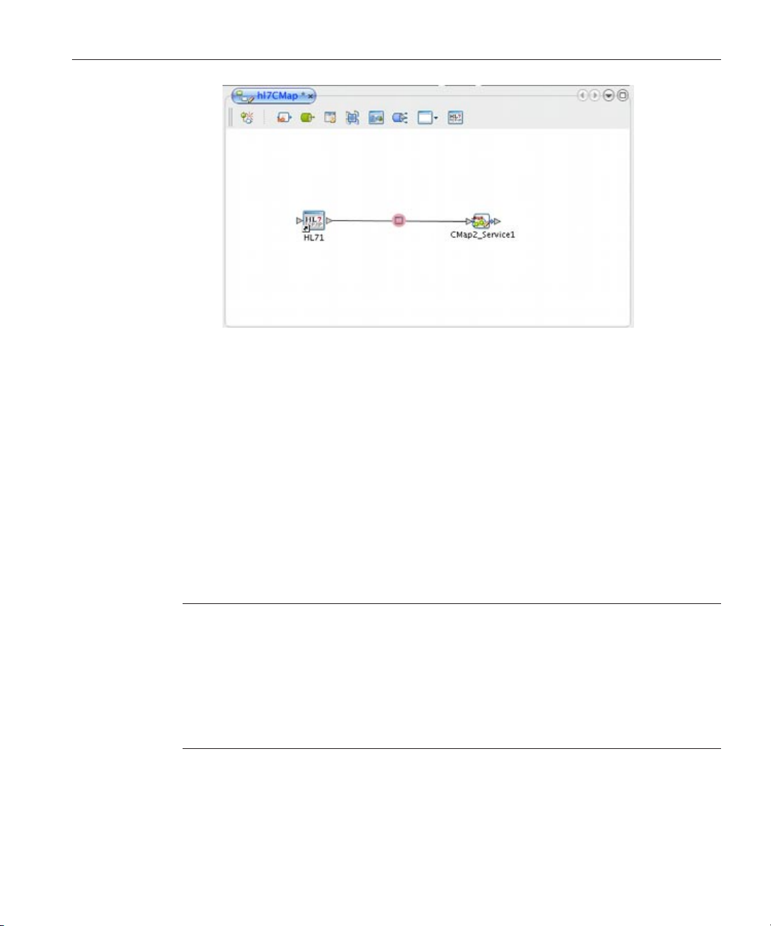
The TCP/IP HL7 Adapter appears on the link.
Sun Adapter forTCP/IPHL7User's Guide • October 200928
Page 29
Adding and Conguring a TCP/IP HL7 Adapter in a Connectivity Map
FIGURE 1 Adapter Location
6
Modify the Adapter properties, as described in “Modifying the TCP/IP HL7 Adapter Properties in
the Connectivity Map”on page 29
.
Modifying the TCP/IP HL7 Adapter Properties in the Connectivity Map
You can modify an Adapter's properties after it is created in the Connectivity Map. The
properties you modify in the Connectivity Map apply only to the specic Adapter you are
conguring. For information on modifying system-wide Adapter properties, see
Sun Adapter for TCP/IP HL7 Environment Properties” on page 91
Tip – A description of each parameter is displayed in the Description box when that parameter is
.
selected, providing an explanation of any required settings or options. Properties are also
described in the following topics:
■
“TCP/IP HL7 V2 Adapter Inbound Connectivity Map Properties” on page 30
■
“TCP/IP HL7 V2 Adapter Outbound Connectivity Map Properties” on page 49
■
“TCP/IP HL7 V3 Adapter Inbound Connectivity Map Properties” on page 64
■
“TCP/IP HL7 V3 Adapter Outbound Connectivity Map Properties” on page 79
Sun Adapter forTCP/IPHL7User's Guide 29
“Conguring
Page 30

TCP/IP HL7V2 AdapterInbound Connectivity Map Properties
▼
Modifying Adapter Properties in the Connectivity Map
From the Connectivity Map, double-click the Adapter icon located in the link between the
1
TCP/IP HL7 External Application and the Service.
The Adapter Properties Editor appears, and displays either inbound or outbound properties
depending on the link to the Service.
In the explorer panel on the left of the Properties Editor,expand the tree until you see the
2
category you want to modify and then select that category.
For example, to modify server port binding properties, expand TCPIP Inbound Settings and
then select Server Port Binding.
Modify a property by either selecting a new value from a drop-down list (if available) or by
3
typing a new value in the propertyeld.
Tip – Click on the ellipsis button next to a property eld to open a separate conguration dialog
box. This is helpful for large values that cannot be fully displayed in the property eld. Enter the
property value in the dialog box and click OK. The value appears in the parameter’s property
eld.
(Optional)To record notes and information about the currently selectedproperty, click inside
4
the Comments box in the lowerleft of the editor and enter the text.
This information is saved for future reference.
When you are done conguring the properties, click OK.
5
TCP/IP HL7 V2 Adapter Inbound Connectivity Map Properties
The TCP/IP HL7 V2 inbound adapter conguration properties are organized into the following
sections on the Properties Editor accessed from the Connectivity Map:
■
“General Inbound Settings – TCP/IP HL7 V2 Inbound Adapter” on page 31
■
“TCPIP Inbound Settings — TCP/IP HL7 V2 Inbound Adapter” on page 32
■
“TCPIP Inbound Settings - Server Port Binding — TCP/IP HL7 V2 Inbound Adapter” on
page 35
■
“TCPIP Inbound Settings - Client Connection Establishment — TCP/IP HL7 V2 Inbound
Adapter” on page 35
■
“TCPIP Inbound Settings - Inbound Connection Management — TCP/IP HL7 V2 Inbound
Adapter” on page 35
■
“TCPIP Inbound Schedules - Listener Schedule — TCP/IP HL7 V2 Inbound Adapter” on
page 36
■
“TCPIP Inbound Schedules - Service Schedule TCP/IP HL7 V2 Inbound Adapter” on
page 38
Sun Adapter forTCP/IPHL7User's Guide • October 200930
Page 31

TCP/IP HL7V2 AdapterInbound Connectivity Map Properties
■
“HL7 Acknowledgment — TCP/IP HL7 V2 Inbound Adapter” on page 39
■
“Lower Layer Protocol — TCP/IP HL7 V2 Inbound Adapter” on page 40
■
“Sequence Number Protocol — TCP/IP HL7 V2 Inbound Adapter” on page 41
■
“HL7 MSH Segment — TCP/IP HL7 V2 Inbound Adapter” on page 41
■
“HL7 SFT Segment — TCP/IP HL7 V2 Inbound Adapter” on page 44
■
“Communication Control — TCP/IP HL7 V2 Inbound Adapter” on page 45
■
“HL7 Recourse Action — TCP/IP HL7 V2 Inbound Adapter” on page 47
General Inbound Settings – TCP/IP HL7 V2 Inbound Adapter
The following table lists and describes the TCP/IP HL7 V2 inbound adapter properties that
appear on the General Inbound Settings page of the Properties Editor accessed from the
Connectivity Map.
TABLE 2 Connectivity Map - General Inbound Settings
Name Description
Max Data Size A number that indicates the maximum amount of data that the programs can
hold internally. The valid range is a numeric value from 1 to 2147483647 bytes
(2GB), which is the maximum value of a Java integer.
Scope Of State The scope of the state object, which is a Message Library node. Select one of the
following options for this property:
■
Resource Adapter Level – The state has the same life cycle as the resource
adapter.
■
Connection Level – The state has the same life cycle as the connection.
■
OTD Level – The state has the same life cycle as the Message Library object.
This scope represents the life cycle of the state.
Dedicated Session Mode An indicator of whether the server Dedicated Session Mode is enabled. When the
server Dedicated Session Mode is enabled, the current client’srequest exclusively
holds the server port to which it connects. The next client’srequest to the same
port is blocked or rejected until the previous request concludes and releases the
connection.
Select true to enable the Dedicated Session Mode, or select false to disable the
Dedicated Session Mode.
Sun Adapter forTCP/IPHL7User's Guide 31
Page 32

TCP/IP HL7V2 AdapterInbound Connectivity Map Properties
TCPIP Inbound Settings — TCP/IP HL7 V2 Inbound Adapter
The following table lists and describes the properties on the TCPIP Inbound Settings page of the
Properties Editor accessed from the Connectivity Map. These properties congure the Java
socket and server socket options.
TABLE 3 Connectivity Map - TCPIP Inbound Settings
Name Description
Connection Type The way the adapter establishes the TCP/IP connection. Select one of the
following options:
■
Client – The adapter connects to an external server (host/port) to establish
the connection. The adapter is in active mode.
■
Server – The adapter waits and listens on a certain port for an incoming
connection request from an external client. Once the request is received, the
adapter accepts the request and establishes the connection. The adapter is in
passive mode.
Server is the default setting. Unless you specically require Client mode, leave the
default value.
ServerSO Timeout The value (in milliseconds) of the SO_TIMEOUT parameter for ServerSocket. The
timeout must be greater than zero (0). A timeout of zero is interpreted as an
innite timeout.
This value is used for the ServerSocket.accept() method. When this option is
set to a non-zero timeout, calling accept() for this ServerSocket will block for
the congured length of time. If the timeout expires, a
java.net.SocketTimeoutException (or java.net.InterruptedIOException)
is thrown, but the ServerSocket remains valid.
Enable this option prior to entering the blocking operation. This property is only
used when the Connection Type property is set to Server.
Server Socket Factory
Implementation Class
Name
Sun Adapter forTCP/IPHL7User's Guide • October 200932
The name of the Java class that implements the server socket factory. This class is
used to create the server socket. If you have provided your own server socket
implementation, enter the name of the Java class that contains this
implementation here. The factory implementation class must implement the
com.stc.connector.tcpip.model.factory.TCPIPSocketFactory interface. A
default interface,
com.stc.connector.tcpip.model.factory.TCPIPSocketFactoryImpl,is
provided.
Page 33

TCP/IP HL7V2 AdapterInbound Connectivity Map Properties
TABLE 3 Connectivity Map - TCPIP Inbound Settings (Continued)
Name Description
Keep Alive An indicator of whether the client’s SO_KEEPALIVE option is enabled or
disabled. Select true to enable SO_KEEPALIVE;otherwise, select false.
When the option is enabled for a TCP socket and no data has been exchanged
across the socket in either direction for two hours, TCP automatically sends a
KEEPALIVE probe to the peer (the actual value is implementation dependent).
This probe is a TCP segment to which the peer must respond. One of three
responses is expected:
1. The peer responds with the expected ACK. The application is not notied
(since everything is OK). TCP will send another probe following another two
hours of inactivity.
2. The peer responds with an RST, which tells the local TCP that the peer host
has crashed and rebooted. The socket is closed.
3. There is no response from the peer. The socket is closed. The purpose of this
option is to detect if the peer host has crashed. This is used for the accepted
client Socket.
Note – For some properties, the server socket itself does not have direct property
settings associated with it. Instead, the properties map to the accepted client
socket.
Receive Buer Size Anumber indicating the receive buer size. This is the value of the SO_RCVBUF
option for the current socket, which is the buer size used by the operating system
for input on this socket. It provides an estimate of the size of the underlying
buers used by the platform for incoming network I/O.
When used in set mode, this is a suggestion for the kernel from the application
regarding the size of buers to use for the data to be received over the socket.
When used in get mode, this must return the actual size of the buer used by the
platform when receiving data on this socket.
Send Buer Size A number indicating the send buer size. This is the value of the SO_SNDBUF
option for the current socket, which is the buer size used by the operating system
for output on this socket. It provides an estimate of the size of the underlying
buers used by the platform for outgoing network I/O.
When used in set mode, this is a suggestion for the kernel from the application
regarding the size of buers to use for the data to be sent over the socket. When
used in get mode, this must return the actual size of the buer used by the
platform when sending out data on this socket.
Sun Adapter forTCP/IPHL7User's Guide 33
Page 34

TCP/IP HL7V2 AdapterInbound Connectivity Map Properties
TABLE 3 Connectivity Map - TCPIP Inbound Settings (Continued)
Name Description
SoLinger An indicator of whether the adapter performs a “linger-on-close” timeout. This
SoLinger Timeout The server’s linger–on–close timeout in seconds. Use SoLinger Timeout when
SoTimeout The value of the SoTimeout in milliseconds. This is used for the accepted client
option disables or enables an immediate return from a call to the close() method
for a TCP Socket. To enable the linger-on-close timeout, select true; otherwise,
select false.
If you enable this property, specify the maximum length of the timeout in the
SoLinger Timeout property.
SoLinger is set to true (see the description for SoLinger above). You can specify
an integer between -1 and 65535. The default is -1 seconds, which indicates that
the SoLinger option is disabled.
When SoLinger is set to true, the SoLinger Timeout value indicates the
following:
■
A non-zero integer means that calling close() will block pending the
transmission and acknowledgement of all data written to the peer. When all
data is written, the socket is closed gracefully. Upon reaching the linger
timeout value specied here, the socket is closed forcefully with a TCP RST. If
the specied timeout value exceeds 65,535 it will be reduced to 65,535.
■
A zero integer means that a forceful close is performed immediately.
socket. You can enter a value greater than or equal to zero (0). When set to zero
(0), the timeout is innite.
With this option set to a non-zero value, calling the read() method on the input
stream associated with this socket will block for only the congured length of
time. If the timeout expires, a java.io.InterruptedIOException or
java.net.SocketTimeoutException is thrown, but the socket remains valid.
Enable this option prior to entering the blocking operation.
TcpNoDelay An indicator of whether data packets that are smaller than the maximum transfer
unit (MTU) size are sent out immediately over the network (this refers to Nagle’s
algorithm). Select one of the following options:
■
True – Indicates that the server allows data packets that are smaller than the
MTU size to be sent out immediately over the network. This can improve
performance for higher-speed networks.
■
False– Indicates that the server does not allow data packets that are less than
the MTU size be sent out immediately over the network.
This is used for the accepted client socket.
Sun Adapter forTCP/IPHL7User's Guide • October 200934
Page 35

TCP/IP HL7V2 AdapterInbound Connectivity Map Properties
TCPIP Inbound Settings - Server Port Binding — TCP/IP HL7 V2 Inbound Adapter
The following table lists and describes the properties that appear on the Server Port Binding
page of the Properties Editor accessed from the Connectivity Map. The properties dene the
server port binding retry options. This section is only used when the Connection Type under
TCPIP Inbound Settings is set to Server.
TABLE 4 ConnectivityMap - TCPIP Inbound Settings - Server Port Binding
Name Description
Max Binding Retry The maximum number of times the adapter attempts to bind to the specied
TCP/IP port on the localhost. This value must be an integer.
Retry Binding Interval The length of time (in milliseconds) the adapter waits between attempts to bind to
the specied TCP/IP port on the localhost.
TCPIP Inbound Settings - Client Connection Establishment — TCP/IP HL7 V2 Inbound Adapter
The following table lists and describes the property that appears on the Client Connection
Establishment page of the Properties Editor accessed from the Connectivity Map. This property
denes a wait time before connecting to the external system. This section is only used when the
Connection Type under TCPIP Inbound Settings is set to Client.
TABLE 5 ConnectivityMap - TCPIP Inbound Settings - Client ConnectionEstablishment
Name Description
Time to Wait Before
Attempting Connection
The length of time (in milliseconds) that the adapter waits before attempting to
connect to the external system.
TCPIP Inbound Settings - Inbound Connection Management — TCP/IP HL7 V2 Inbound Adapter
The following table lists and describes the properties that appear on the Inbound Connection
Management page of the Properties Editor accessed from the Connectivity Map. These
properties manage the connection to inbound systems. For example, these properties include
the connection pool and the life cycle of the accepted connection.
Sun Adapter forTCP/IPHL7User's Guide 35
Page 36

TCP/IP HL7V2 AdapterInbound Connectivity Map Properties
TABLE 6 ConnectivityMap - TCPIP Inbound Settings - Inbound Connection Management
Name Description
Max Connection Pool
Size
Scope Of Connection The scope of the accepted connection that is used by the adapter. Select one of the
Close Notication A String indicating the trigger value that noties the server to close the
Idle Timeout The length of time (in milliseconds) for inactivity of the requestor (client). The
The maximum number of concurrent connections allowed for the specic
listener or monitor that is listening or monitoring the specied TCP/IP port. 0
(zero) indicates that there is no limit.
This value indicates the capability or availability of this server’s services. Each
connection request from a client gains one concurrent connection. This value
also indicates the maximum number of clients that can concurrently connect to
this server’s services and can be served by the specic listener or monitor at the
same time.
following options:
■
Resource Adapter Level – The resource adapter closes the connection upon
request (by way of ClosureCommandMessage) so the connection may “keep
alive” during multiple executions of the Collaboration.
■
Collaboration Level – The resource adapter closes the connection once the
Collaboration has been executed so the connection has the same life cycle as
the Collaboration.
connection. When the server receives a notication with content that matches
this parameter’s value, the server safely closes the connection and cancels any
corresponding schedules.
The default value is QUIT.
adapter attempts to detect in/out activity from the client. If there is no client
activity for a specied time period, then the connection is closed from the server
side to release the resource. To disable idle timeout checking, specify 0 (zero) for
this parameter.
TCPIP Inbound Schedules - Listener Schedule — TCP/IP HL7 V2 Inbound Adapter
The following table lists and describes the properties that appear on the Listener Schedule page
of the Properties Editor accessed from the Connectivity Map. These properties congure the
scheduler used by the inbound TCP/IP server. The server waits for a new client connection
establishment request. These parameters are used to congure the listener.
Two Java EE schedulers are available, both of which provide the functionality required by the
inbound TCP/IP Server.
Sun Adapter forTCP/IPHL7User's Guide • October 200936
Page 37

TCP/IP HL7V2 AdapterInbound Connectivity Map Properties
■
Timer Service – Available for Java EE, this scheduler is congured using the At Fixed Rate,
Delay, and Period properties.
■
Work Manager – Availablefor Java EE (JCA 1.5 and above), this scheduler is congured
using the Delay and Period properties.
TABLE 7 ConnectivityMap - TCPIP Inbound Schedules - Listener Schedule
Name Description
Scheduler The scheduler type for this inbound communication. Select one of the following
options:
■
Timer Service – The task is scheduled through the Java EE Timer Service.
Timer Service is supported by Java EE.
■
Work Manager – The task is scheduled through the Java EE Work Manager.
Work Manager is supported by Java EE (JCA1.5 and above).
If your container doesn’t support JCA Work Manager, select Timer Service.
Schedule Type This property, though visible from the Properties Editor, is disabled. The only
available schedule type is Repeated, indicating that the task is scheduled for
repeated execution at regular intervals dened by the Period property.
Delay An integer indicating the length of time (in milliseconds) before the task is
executed. This property applies to both the Timer Service and the Work Manager.
Period An integer indicating the length of time (in milliseconds) between successive task
executions. This property applies to both the Timer Service and the Work
Manager.
At Fixed Rate An indicator of whether a xed-rate execution or xed-delay execution is used.
This property applies to the Timer Service conguration only. Select true to
indicate xed-rate; select false to indicate xed-delay.
■
Fixed-Rate – Each execution is scheduled relative to the scheduled time of
the initial execution. If an execution is delayed for any reason (such as
garbage collection or other background activity), two or more executions
occur in rapid succession to “catch up.”In the long run, the frequency of
execution is exactly the reciprocal of the specied period, assuming the
system clock underlying Object.wait(long) is accurate.
■
Fixed-Delay – Each execution is scheduled relative to the actual time of the
previous execution. If an execution is delayed for any reason (such as garbage
collection or other background activity), subsequent executions are delayed
as well. As a result, the frequency of execution is generally slightly lower than
the reciprocal of the specied period, assuming the system clock underlying
Object.wait(long) is accurate.
Sun Adapter forTCP/IPHL7User's Guide 37
Page 38

TCP/IP HL7V2 AdapterInbound Connectivity Map Properties
TCPIP Inbound Schedules - Service Schedule TCP/IP HL7 V2 Inbound Adapter
The following table lists and describes the properties that appear on the Service Schedule page
of the Properties Editor accessed from the Connectivity Map. These properties congure the
scheduler used by the TCP/IP server that executes the business tasks (Collaboration rules) over
the existing connection. This scheduler aects the actual business rules you dene.
You can use either of the following two Java EE schedulers, both of which provide the
functionality required by the inbound TCP/IP server.
■
Timer Service – Available for Java EE, this scheduler is congured using the At Fixed Rate,
Delay, Period, and Schedule Typeproperties.
■
Work Manager – Availablefor Java EE (JCA 1.5 and above), this scheduler is congured
using the Delay, Period, and Schedule Typeproperties.
TABLE 8 ConnectivityMap - TCPIP Inbound Schedules - Service Schedule
Name Description
Scheduler The scheduler type for this inbound communication. Select one of the following
options:
■
Timer Service – The task is scheduled through the Java EE Timer Service.
Timer Service is supported by Java EE.
■
Work Manager – The task is scheduled through the Java EE Work Manager.
Work Manager is supported by Java EE (JCA1.5 and above).
If your container doesn’t support JCA Work Manager, select Timer Service.
Schedule Type An indicator of whether the task is scheduled to occur once or be repeated. This
property applies to both the Timer Service and the Work Manager. Select one of
the following options:
■
OneTime – The task is scheduled for one-time execution.
■
Repeated – The task is scheduled for repeated execution at regular intervals
dened by Period property, described below.
Delay An integer indicating the length of time (in milliseconds) before the task is
executed. This property applies to both the Timer Service and the Work Manager.
Period An integer indicating the length of time (in milliseconds) between successive task
executions. This property applies to both the Timer Service and the Work
Manager. This is used when the Schedule Type property is set to Repeated.
Sun Adapter forTCP/IPHL7User's Guide • October 200938
Page 39

TCP/IP HL7V2 AdapterInbound Connectivity Map Properties
TABLE 8 ConnectivityMap - TCPIP Inbound Schedules - Service Schedule (Continued)
Name Description
At Fixed Rate An indicator of whether a xed-rate execution or xed-delay execution is used.
This property applies to the Timer Service conguration only, and is used when
the Schedule Type property is set to Repeated. Select true to indicate xed-rate;
select false to indicate xed-delay.
■
Fixed-Rate – Each execution is scheduled relative to the scheduled time of
the initial execution. If an execution is delayed for any reason (such as
garbage collection or other background activity), two or more executions
occur in rapid succession to “catch up.”In the long run, the frequency of
execution is exactly the reciprocal of the specied period, assuming the
system clock underlying Object.wait(long) is accurate.
■
Fixed-Delay – Each execution is scheduled relative to the actual time of the
previous execution. If an execution is delayed for any reason (such as garbage
collection or other background activity), subsequent executions are delayed
as well. As a result, the frequency of execution is generally slightly lower than
the reciprocal of the specied period, assuming the system clock underlying
Object.wait(long) is accurate.
HL7 Acknowledgment —TCP/IP HL7 V2 Inbound Adapter
The following table lists and describes the properties that appear on the HL7 Acknowledgment
page of the Properties Editor accessed from the Connectivity Map. These properties dene how
the application acknowledgment events are handled.
TABLE 9 Connectivity Map - HL7 Acknowledgment
Name Description
Acknowledgment Level An indicator of whether the external application sends an Acknowledgement
after successfully receiving a message, or after the message has been successfully
committed to the application database. Select one of the following options:
■
A – Application acknowledgment. The acknowledgement is sent after the
message is successfully and functionally processed by one receiving system.
■
C – Commit (accept) acknowledgment. The acknowledgement is sent when
the message is successfully received.
Sun Adapter forTCP/IPHL7User's Guide 39
Page 40

TCP/IP HL7V2 AdapterInbound Connectivity Map Properties
TABLE 9 Connectivity Map - HL7 Acknowledgment (Continued)
Name Description
eGate Sends App Acks An indicator of whether the HL7 application acknowledgment sent to the
Forward External Acks An indicator of whether the HL7 application acknowledgment is forwarded to the
Timeout For Delayed Ack A number indicating the timeout value for delayed ACK in milliseconds. This
external system is generated by the adapter or forwarded from the application
server. Select one of the following options:
■
true – Indicates that the application server receives or creates the HL7
application acknowledgment and sends it to the adapter, which in turn
forwards it to the external system.
■
false – Indicates that the adapter creates and sends the HL7 application
acknowledgment directly to the external system.
This property is used in the inbound Collaboration code.
application server. When an HL7 application acknowledgment is received, it is
sometimes necessary to forward the contents of the HL7 application
acknowledgment to the application server (as data). This property is used for
inbound Collaboration code.
Select true if the adapter forwards HL7 application acknowledgments from the
external system to the application server for processing; otherwise select false.
property is used in the inbound Collaborationcode.
Lower Layer Protocol — TCP/IP HL7 V2 Inbound Adapter
The following table lists and describes the properties that appear on the Lower Layer Protocol
page of the Properties Editor accessed from the Connectivity Map. These properties dene the
Lower Layer Protocol (LLP) conguration.
TABLE 10 Connectivity Map - Lower Layer Protocol
Name Description
LLP Type The lower layer protocol (LLP) type. Select one of the following options:
Start Block Character The rst envelope marker character in the HL7 envelope, as a decimal ASCII
Sun Adapter forTCP/IPHL7User's Guide • October 200940
■
MLLP (Minimal Lower Layer Protocol)
■
HLLP (Hybrid Lower Layer Protocol)
■
MLLP v2.0 (Minimal Lower Layer Protocol v2.0)
For more information on the available envelope types, see “Lower Layer
Protocol” on page 23
.
number. Enter a number from 1 to 127. Unless there is a conict, the value should
be ASCII VT (decimal 11).
Page 41

TCP/IP HL7V2 AdapterInbound Connectivity Map Properties
TABLE 10 Connectivity Map - LowerLayer Protocol (Continued)
Name Description
End Data Character The second to the last envelope marker character in the HL7 envelope, as a
decimal ASCII number. Enter a number from 1 to 127. Unless there is a conict,
the value should be ASCII FS (decimal 28).
End Block Character The last envelope marker character in the HL7 envelope, as a decimal ASCII
number. Enter a number from 1 to 127. To strictly comply with the HL7
Standard, this property must be set to a carriage return (decimal 13).
HLLP Checksum Enabled An indicator of whether the HLLP Checksum is enabled or disabled.
Select true to enable checksum values; otherwise select false.
Max Number of Retries The maximum number of times the adapter tries to send a message upon
receiving the MLLP v2.0 Negative Commit Acknowledgement from the peer
before giving up. This property is used by the adapter in outbound mode. Enter
any integer.
Sequence Number Protocol — TCP/IP HL7 V2 Inbound Adapter
The following table lists and describes the property that appears on the Sequence Number
Protocol page of the Properties Editor accessed from the Connectivity Map. This property
enables or disables HL7 sequence numbering, which is used to help prevent duplication of data.
TABLE 11 Connectivity Map - Sequence NumberProtocol
Name Description
Sequence Number
Enabled
An indicator of whether sequence numbering is enabled or disabled. Enabling
sequence numbering helps prevent duplication of data. Select true to enable
sequence numbering; otherwise select false.
HL7 MSH Segment — TCP/IP HL7 V2 Inbound Adapter
The following table lists and describes the properties that appear on the HL7 MSH Segment
page of the Properties Editor accessed from the Connectivity Map. These properties dene the
conguration of the MSH segment of the HL7 message. For more information about this
segment, refer to the HL7 specication (
Sun Adapter forTCP/IPHL7User's Guide 41
http://www.hl7.org).
Page 42

TCP/IP HL7V2 AdapterInbound Connectivity Map Properties
TABLE 12 Connectivity Map - HL7 MSH Segment
Name Description
Field Separator The character that separates the segment ID and the rst real eld. This value
denes the character that is used as a separator for the rest of the message and is
the rst eld in the HL7 MSH segment (MSH-01).
The value is a decimal ASCII number, and the allowed range is 1 to 127. The
default setting is 124, which is the pipe character (|).
Encoding Characters Encoding characters in the following order:
■
Component separator
■
Repetition separator
■
Escape character
■
Subcomponent separator
This is the second eld in the HL7 MSH segment (MSH-02).
The default is ^~\& (ASCII 94, 126, 92, and 38) respectively.
Sending Application A user-dened value for the sending application among other applications within
the network enterprise. The network enterprise consists of the applications that
participate in the exchange of HL7 messages within the enterprise. The default is
Sun HL7 adapter.
This is the third eld in the HL7 MSH segment (MSH-03).
Sending Facility A user-dened value that further identies the sending application among
multiple identical instances of the application running on behalf of dierent
organizations. The default is Sun HL7 adapter.
This is the fourth eld in the HL7 MSH segment (MSH-04).
Receiving Application A user-dened value for the receiving application among other applications
within the network enterprise. The default value is Sun HL7 adapter.
This is the fth eld in the HL7 MSH segment (MSH-05).
Receiving Facility A user-dened value that further identies the receiving application among
multiple identical instances of the application running on behalf of dierent
organizations. The default value is Sun HL7 adapter.
This is the sixth eld in the HL7 MSH segment (MSH-06).
Security The implemented application level security features.
This is the eighth eld in the HL7 MSH segment (MSH-08).
Sun Adapter forTCP/IPHL7User's Guide • October 200942
Page 43

TCP/IP HL7V2 AdapterInbound Connectivity Map Properties
TABLE 12 Connectivity Map - HL7 MSH Segment (Continued)
Name Description
Processing ID The subcomponent processing ID of the MSH-11 eld. MSH-11 is used to
indicate whether a message is processed as dened in the HL7 Application
processing rules.
Specify one of the following options:
■
D - The message is part of a debugging system.
■
P - The message is part of a production system.
■
T - The message is part of a training system.
In some cases there may be an additional value, the processing mode,
following the initial value. This value can be A (archive), R (restore from
archive), or I (initial load).
Version ID The HL7 version as displayed in HL7 Table 0104 - Version ID. This value is
matched by the receiving system to its own version to ensure that messages are
interpreted correctly. The default value is 2.5.
This is the 12th eld in the HL7 MSH segment (MSH-12).
Country Code A code that indicates the country of origin for the message (see HL7 Table 0399).
Use the 3-character (alphabetic) form of ISO 3166. This value is used to specify
default elements in a message, such as currency. The default value is USA.
This is the 17th eld in the HL7 MSH segment (MSH-17).
Character Set The character set(s) used by the messages (see HL7 Table 0211). If the eld is left
blank, the character set is assumed to be the 7-bit ASCII set. The default value is
8859/1 (printable 7-bit ASCII character set).
This is the 18th eld in the HL7 MSH segment (MSH-18).
Principal Language of
Message
The 2-character ISO 639 alphabetic code that species the principal language of
the message.
This is the 19th eld in the HL7 MSH segment (MSH-19).
Alternate Character Set
Handling Scheme
The value for the alternate character set handling scheme to be used when any
alternative character sets are used and a special handling scheme is necessary (see
HL7 Table 0356). Possible values are ISO 2022-1994, 2.3,or<null> (blank).
Leaving the eld blank indicates that no character set switching will occur.
This is the 20th eld in the HL7 MSH segment (MSH-20).
Conformance StatementIDA unique identier that applies to a query’s conformance statement. It can also be
used as a Message Prole Identier to assert constancy with a message prole
(grammar, syntax, usage, and so on).
This is the 21st eld in the HL7 MSH segment (MSH-21).
Sun Adapter forTCP/IPHL7User's Guide 43
Page 44

TCP/IP HL7V2 AdapterInbound Connectivity Map Properties
TABLE 12 Connectivity Map - HL7 MSH Segment (Continued)
Name Description
Validate MSH An indicator of whether to validate the MSH segment of the data message (for
HL7 SFT Segment — TCP/IP HL7 V2 Inbound Adapter
The following table lists and describes the properties that appear on the HL7 SFT Segment page
of the Properties Editor accessed from the Connectivity Map. These properties dene the
conguration of the SFT segment of the HL7 message, which provides additional information
about one or more software products used as sending applications. The primary purpose of this
segment is for diagnostic use. There may be additional uses per site-specic agreements. For
more information about this segment, refer to the HL7 specication (
Note – The SFT segment is available starting with HL7 version 2.5.
inbound) and the MSH segment of the ACK (for outbound). Select true if you
want the Collaboration to validate the MSH segment; otherwise select false.
This parameter is used in Collaboration code.
Note – This property does not aect structural validation of the entire HL7
message itself. Structural validation is always performed.
http://www.hl7.org).
TABLE 13 Connectivity Map - HL7 SFT Segment
Name Description
Enable Anindicator of whether the SFT optional segment is enabled in the ACK. Select
true to enable the segment; otherwise select false.
Note – If Enable is set to true, and the HL7 version is not congured as 2.5, the
adapter will error upon startup.
Software Vendor
Organization
Sun Adapter forTCP/IPHL7User's Guide • October 200944
The name of the company that publishes or distributes the sending software that
created the transaction. This eld identies the vendor responsible for
maintaining the application. The purpose of this eld, along with the remaining
elds in this segment, is to provide a more complete prole of the sending
applications.
This is the rst eld in the HL7 SFT segment (SFT-01).
Page 45

TCP/IP HL7V2 AdapterInbound Connectivity Map Properties
TABLE 13 Connectivity Map - HL7 SFT Segment (Continued)
Name Description
Software Certied
Version or Release
Number
Software Product Name The name of the software product that submitted the transaction. The default
Software Binary ID The unique software binary ID. Software binary IDs are issued by a vendor for
Software Product
Information
The latest software version number or release number for the sending system,
which helps provide a more complete prole of the application that is sending or
receiving HL7 messages.
Version numbers are important in identifying the specic release of an
application. In some situations, the receiving application validates the software
certied version or release number against a list of certied versions or releases of
the particular software. This helps determine whether the sending application
adheres to specic business rules required by the receiving application.
Alternatively, the software may perform dierent processing, depending on the
version of the sending software.
This is the second eld in the HL7 SFT segment (SFT-02).
value is Sun TCP/IP HL7 adapter Intelligent Adapter.
This is the third eld in the HL7 SFT segment (SFT-03).
each unique software version instance. These IDs are used to dierentiate
between multiple versions of the same software. Identical primary IDs indicate
that the software is identical at the binary level, but conguration settings may
dier.
This is the fourth eld in the HL7 SFT segment (SFT-04).
Any additional information about the sending application for more complete
identication. This could include a description of the software application,
conguration settings, modications made to the software, and so on. This
information is used for diagnostic purposes and provides greater exibility in
identifying the application software.
This is the fth eld in the HL7 SFT segment (SFT-05).
Software Install Date The date on which the submitting software was installed at the sending site. The
software installation date on its own can often provide key information about the
behavior of the application.
This is the sixth eld in the HL7 SFT segment (SFT-06).
Communication Control — TCP/IP HL7 V2 Inbound Adapter
The following table lists and describes the properties that appears on the Communication
Control page of the Properties Editor accessed from the Connectivity Map. These properties
dene how data is transferred (that is, sent and received) over the TCP/IP connection.
Sun Adapter forTCP/IPHL7User's Guide 45
Page 46

TCP/IP HL7V2 AdapterInbound Connectivity Map Properties
TABLE 14 Connectivity Map - Communication Control
Name Description
Time To Wait For A
Response
The amount of time (in milliseconds) that the adapter waits for a response from
the external system before taking recourse action (see Action on No Response in
HL7 Recourse Action). Any data from the external system is considered a
response.
This property corresponds to the initial read/receive operation timeout. Once a
response is received, the subsequent read/receive operation uses the value
specied for SoTimeout ( see
TCPIP Inbound Settings). A value of 0 (zero)
indicates an innite timeout.
Max Empty Read Retry The maximum number of times the adapter attempts to read data from the
external system after the read/receive operation returns nothing. This applies to
the read or receive operation after a response starts to arrive. Empty Read means
that a timeout occurs on the read/receive operation, which uses the SoTimeout
parameter in the TCPIP Server Base Settings section as the timeout setting (see
TCPIP Inbound Settings). The corresponding recourse action is specied by the
Action on Max Failed Read Retry (see
HL7 Recourse Action).
Max No Response The maximum number of response timeouts the adapter allows while waiting for
data from the external system before taking recourse action (see ActiononMax
No Response in
HL7 Recourse Action).
This property is used in the inbound Collaboration code. It is only used by
outbound adapters and works in conjunction with the Resend option of the
Action on No Response property. It congures the adapter to resend the last
message for the specied maximum number of times before the subsequent
recourse action is taken.
Max NAK Receive Retry The maximum number of negative acknowledgments (NAKs) the adapter
receives before taking recourse action (see Action on Max Nak Received in
Recourse Action
).
HL7
This property is used for the inbound Collaboration code.
Max NAK Send Retry The maximum number of negative acknowledgments (NAKs) the adapter sends
before taking recourse action (see Action on Max Nak Sent in
).
Action
HL7 Recourse
This property is used in the inbound Collaboration code.
Max Canned NAKSend
Retry
The maximum number of canned negative acknowledgments that the adapter
sends before taking recourse action (see Action on Max Nak Sent in
Recourse Action
). A value of 0 (zero) indicates that the adapter will not attempt to
HL7
create or send a canned NAK.
Enable Journaling An indicator of whether message journaling is enabled. To enable message
journaling, select true; otherwise select false.
This property is used for inbound Collaborationcode.
Sun Adapter forTCP/IPHL7User's Guide • October 200946
Page 47

TCP/IP HL7V2 AdapterInbound Connectivity Map Properties
HL7 Recourse Action — TCP/IP HL7 V2 Inbound Adapter
The following table lists and describes the properties that appear on the HL7 Recourse Action
page of the Properties Editor accessed from the Connectivity Map. These properties dene the
actions the adapter takes when operations occur outside the congured constraints.
TABLE 15 Connectivity Map - HL7 Recourse Action
Name Description
Action on No Response The action the adapter takes when no ACK is received from the external system in
the allotted time. The amount of time is determined by the Time To Wait For A
Response property (see
options:
■
Exit – The adapter terminates its connection with the external system and
shuts down.
■
Resend – The adapter attempts to resend the message to the external system.
The Resend option is only allowed when sequence numbering is in eect.
■
Reset – The adapter closes its connection with the external system and goes
through the connection scenario.
This property is used for inbound Collaborationcode.
Communication Control). Select one of the following
Action on Max No
Response
The action the adapter takes when it attempts to send a message to the external
system the maximum allowed number of times and does not receive any response
(HL7 Application Acknowledgement) from the external system. The maximum
number times the adapter sends a message without receiving a response is
determined by the Max No Response property (see
Communication Control).
Select one of the following options:
■
Exit – The adapter terminates its connection with the external system and
shuts down.
■
Reset – The adapter closes its connection with the external system and goes
through the connection scenario.
This property is used for inbound Collaborationcode.
Action on Max Failed
Read Retry
The action the adapter takes after it has reached the empty read limit set by the
Max Empty Read Retry property. This property is used by inbound adapters only.
Select one of the following recourse options:
■
Exit – The adapter terminates its connection with the external system and
shuts down.
■
Reset – The adapter closes its connection with the external system and goes
through the connection scenario.
This property is used for inbound Collaborationcode.
Sun Adapter forTCP/IPHL7User's Guide 47
Page 48

TCP/IP HL7V2 AdapterInbound Connectivity Map Properties
TABLE 15 Connectivity Map - HL7 Recourse Action (Continued)
Name Description
Action on Nak Received The action the adapter takes when it receives an HL7 Application NAK from the
external system. Select one of the following options:
■
Resend – The adapter attempts to resend the message to the external system.
■
Reset – The adapter closes its connection with the external system and goes
through the connection scenario.
■
Skip Message – The adapter remains connected, but writes the message to an
error queue.
Note – Do not set both the Action On NAK Received and Action On Max NAK
Received properties to Skip Message.
This property is used for inbound Collaborationcode.
Action on Max Nak
Received
The action the adapter takes when the maximum number of HL7 Application
NAKs have been received from the external system, as set by the Max NAK
Receive Retry property (see
Communication Control). Select one of the
following options:
■
Exit – The adapter terminates its connection with the external system and
shuts down.
■
Reset – The adapter closes its connection with the external system and goes
through the connection scenario.
■
Skip Message – The adapter remains connected, but writes the message to an
error queue.
This property is used for inbound Collaborationcode.
Note – Do not set both the Action On NAK Received and Action On Max NAK
Received properties to Skip Message.
Action on Max Nak Sent The action the adapter takes when it has sent the maximum allowed number of
NAKs to the external system, as set by the Max NAK Send Retry parameter (see
Communication Control). Select one of the following options:
■
Exit – The adapter terminates its connection with the external system and
shuts down.
■
Reset – The adapter closes its connection with the external system and goes
through the connection scenario.
This property is used for inbound Collaborationcode.
Sun Adapter forTCP/IPHL7User's Guide • October 200948
Page 49

TCP/IP HL7V2 AdapterOutbound Connectivity Map Properties
TCP/IP HL7 V2 Adapter Outbound Connectivity Map
Properties
The TCP/IP HL7 V2 server outbound adapter conguration properties are organized into the
following sections on the Properties Editor accessed from the Connectivity Map:
■
“General Outbound Settings — TCP/IP HL7 V2 Outbound Adapter” on page 49
■
“TCPIP Outbound Settings — TCP/IP HL7 V2 Outbound Adapter” on page 50
■
“TCPIP Outbound Settings - Client Connection Establishment — TCP/IP HL7 V2
Outbound Adapter” on page 53
■
“TCPIP Outbound Settings - Server Port Binding — TCP/IP HL7 V2 Outbound Adapter” on
page 54
■
“HL7 Acknowledgment — TCP/IP HL7 V2 Outbound Adapter” on page 55
■
“Lower Layer Protocol — TCP/IP HL7 V2 Outbound Adapter” on page 55
■
“Sequence Number Protocol — TCP/IP HL7 V2 Outbound Adapter” on page 56
■
“HL7 MSH Segment — TCP/IP HL7 V2 Outbound Adapter” on page 57
■
“HL7 SFT Segment — TCP/IP HL7 V2 Outbound Adapter” on page 59
■
“Communication Control — TCP/IP HL7 V2 Outbound Adapter” on page 60
■
“HL7 Recourse Action — TCP/IP HL7 V2 Outbound Adapter” on page 62
General Outbound Settings — TCP/IP HL7 V2 Outbound Adapter
The following table lists and describes the TCP/IP HL7 V2 outbound adapter properties that
appear on the General Outbound Settings page of the Properties Editor accessed from the
Connectivity Map.
TABLE 16 Connectivity Map - General Outbound Settings
Name Description
Max Data Size A number that indicates the maximum amount of data that the programs can
hold internally. The valid range is a numeric value from 1 to 2147483647 bytes
(2GB), which is the maximum value of a Java integer.
Scope Of State The scope of the state object, which is a Message Library node. Select one of the
following options for this property:
■
Resource Adapter Level – The state has the same life cycle as the resource
adapter.
■
Connection Level – The state has the same life cycle as the connection.
■
OTD Level – The state has the same life cycle as the Message Library object.
This scope represents the life cycle of the state.
Sun Adapter forTCP/IPHL7User's Guide 49
Page 50

TCP/IP HL7V2 AdapterOutbound Connectivity Map Properties
TCPIP Outbound Settings — TCP/IP HL7 V2 Outbound Adapter
The following table lists and describes the properties on the TCPIP Outbound Settings page of
the Properties Editor accessed from the Connectivity Map. These properties congure the Java
socket and server socket options. For more information, see the Javadocs for Java SDK.
TABLE 17 Connectivity Map - TCPIP Outbound Settings
Name Description
Connection Type The way the adapter establishes the TCP/IP connection. Select one of the
following options:
■
■
Server is the default setting. Unless you specically require Client mode, leave the
default value.
Client – The adapter connects to an external server (host/port) to establish
the connection. The adapter is in active mode.
Server – The adapter waits and listens on a certain port for an incoming
connection request from an external client. Once the request is received, the
adapter accepts the request and establishes the connection. The adapter is in
passive mode.
ServerSo
Timeout
Sun Adapter forTCP/IPHL7User's Guide • October 200950
The value (in milliseconds) of the SO_TIMEOUT parameter for ServerSocket. The
timeout must be greater than zero (0). A timeout of zero is interpreted as an
innite timeout.
This value is used for the ServerSocket.accept() method. When this option is
set to a non-zero timeout, calling accept() for this ServerSocket will block for
the congured length of time. If the timeout expires, a
java.net.SocketTimeoutException (or java.net.InterruptedIOException)
is thrown, but the ServerSocket remains valid.
Enable this option prior to entering the blocking operation. This property is only
used when the Connection Type property is set to Server.
Page 51

TCP/IP HL7V2 AdapterOutbound Connectivity Map Properties
TABLE 17 Connectivity Map - TCPIP Outbound Settings (Continued)
Name Description
Keep Alive An indicator of whether the client’s SO_KEEPALIVE option is enabled or
disabled. Select true to enable SO_KEEPALIVE;otherwise, select false.
When the option is enabled for a TCP socket and no data has been exchanged
across the socket in either direction for two hours, TCP automatically sends a
KEEPALIVE probe to the peer (the actual value is implementation dependent).
This probe is a TCP segment to which the peer must respond. One of three
responses is expected:
1. The peer responds with the expected ACK. The application is not notied
(since everything is OK). TCP will send another probe following another two
hours of inactivity.
2. The peer responds with an RST, which tells the local TCP that the peer host
has crashed and rebooted. The socket is closed.
3. There is no response from the peer. The socket is closed. The purpose of this
option is to detect if the peer host has crashed. This is used for the accepted
client Socket.
Note – For some properties, the server socket itself does not have direct property
settings associated with it. Instead, the properties map to the accepted client
socket.
Receive Buer Size A number indicating the receive buer size. This is the value of the SO_RCVBUF
option for the current socket, which is the buer size used by the operating system
for input on this socket. It provides an estimate of the size of the underlying
buers used by the platform for incoming network I/O.
When used in set mode, this is a suggestion for the kernel from the application
regarding the size of buers to use for the data to be received over the socket.
When used in get mode, this must return the actual size of the buer used by the
platform when receiving data on this socket.
Send Buer Size A number indicating the send buer size. This is the value of the SO_SNDBUF
option for the current socket, which is the buer size used by the operating system
for output on this socket. It provides an estimate of the size of the underlying
buers used by the platform for outgoing network I/O.
When used in set mode, this is a suggestion for the kernel from the application
regarding the size of buers to use for the data to be sent over the socket. When
used in get mode, this must return the actual size of the buer used by the
platform when sending out data on this socket.
Sun Adapter forTCP/IPHL7User's Guide 51
Page 52

TCP/IP HL7V2 AdapterOutbound Connectivity Map Properties
TABLE 17 Connectivity Map - TCPIP Outbound Settings (Continued)
Name Description
SoLinger An indicator of whether the adapter performs a “linger-on-close” timeout. This
option disables or enables an immediate return from a call to the close() method
for a TCP Socket. To enable the linger-on-close timeout, select true; otherwise,
select false.
If you enable this property, specify the maximum length of the timeout in the
SoLinger Timeout property.
SoLinger Timeout The server’s linger–on–close timeout in seconds. Use SoLinger Timeout when
SoLinger is set to true (see the description for SoLinger above). You can specify
an integer between -1 and 65535. The default is -1 seconds, which indicates that
the SoLinger option is disabled.
When SoLinger is set to true, the SoLinger Timeout value indicates the
following:
■
■
SoTimeout The value of the SoTimeout in milliseconds. You can enter a value greater than or
equal to zero (0). When set to zero (0), the timeout is innite.
With this option set to a non-zero value, calling the read() method on the input
stream associated with this socket will block for only the congured length of
time. If the timeout expires, a java.io.InterruptedIOException or
java.net.SocketTimeoutException is thrown, but the socket remains valid.
Enable this option prior to entering the blocking operation.
A non-zero integer means that calling close() will block pending the
transmission and acknowledgement of all data written to the peer. When all
data is written, the socket is closed gracefully. Upon reaching the linger
timeout value specied here, the socket is closed forcefully with a TCP RST. If
the specied timeout value exceeds 65,535 it will be reduced to 65,535.
A zero integer means that a forceful close is performed immediately.
TcpNoDelay An indicator of whether data packets that are smaller than the maximum transfer
unit (MTU) size are sent out immediately over the network (this refers to Nagle’s
algorithm). Select one of the following options:
■
True – Indicates that the server allows data packets that are smaller than the
MTU size to be sent out immediately over the network. This can improve
performance for higher-speed networks.
■
False– Indicates that the server does not allow data packets that are less than
the MTU size be sent out immediately over the network.
This is used for the accepted client socket.
Sun Adapter forTCP/IPHL7User's Guide • October 200952
Page 53

TCP/IP HL7V2 AdapterOutbound Connectivity Map Properties
TABLE 17 Connectivity Map - TCPIP Outbound Settings (Continued)
Name Description
Socket Factory
Implementation Class
Name
The name of the Java class that implements the socket factory. This class is used to
create the socket. If you have provided your own socket implementation, enter
the name of the Java class that contains this implementation here. The factory
implementation class must implement the
com.stc.connector.tcpip.model.factory.TCPIPSocketFactory interface.
The default value is
com.stc.connector.tcpip.model.factory.TCPIPSocketFactoryImpl
TCPIP Outbound Settings - Client Connection Establishment — TCP/IP HL7 V2 Outbound Adapter
The following table lists and describes the properties that appear on the Client Connection
Establishment page of the Properties Editor accessed from the Connectivity Map. These
properties congure how connections are established. This section is only used when the
Connection Type under TCPIP Outbound Settings is set to Client.
TABLE 18 ConnectivityMap - TCPIP Outbound Settings - Client Connection Establishment
Name Description
Time To Wait Before
Attempting Connection
Always Create New
Connection
The length of time (in milliseconds) the adapter waits before attempting to
connect to the external system.
An indicator of whether the adapter always attempts to create a new connection
when a connection establishment request is received. Select on of the following
options:
■
true – The adapter always attempts to create a new connection without
attempting to match an existing connection.
■
false – The adapter attempts to match an existing connection (managed by
the container).
Sun Adapter forTCP/IPHL7User's Guide 53
Page 54

TCP/IP HL7V2 AdapterOutbound Connectivity Map Properties
TABLE 18 ConnectivityMap - TCPIP Outbound Settings - Client Connection Establishment
(Continued)
Name Description
Auto Reconnect Upon
Matching Failure
Max Connection Retry The maximum number of times the adapter attempts to connect to a specic
Retry Connection
Interval
An indicator or whether to attempt to reconnect automatically when the adapter
gets a matching connection from a container, even though this connection is not
valid; for example, the external side of the connection is closed or reset due to the
external application’s logic.
Select one of the following options:
■
true – The adapter discards the invalid matching connection and
automatically attempts to reconnect using a new connection.
■
false – The adapter does not automatically attempt to reconnect using a new
connection. Instead, the adapter defers the reconnect control to the user
business rules. It is up to the business rules to detect this type of failure and act
appropriately.
external TCP/IP destination (host/port) before giving up.
The length of time (in milliseconds) the adapter waits between attempts to
connect to a specic external TCP/IP destination (host or port).
TCPIP Outbound Settings - Server Port Binding — TCP/IP HL7 V2 Outbound Adapter
The following table lists and describes the properties that appear on the Server Port Binding
page of the Properties Editor accessed from the Connectivity Map. The properties dene the
server port binding retry options. This section is only used when the Connection Type under
TCPIP Outbound Settings is set to Server.
TABLE 19 ConnectivityMap - TCPIP Outbound Settings - Server Port Binding
Name Description
Max Binding Retry The maximum number of times the adapter will attempt to bind to the specied
TCP/IP port on the localhost before giving up.
Retry Binding Interval The amount of time (in milliseconds) that the adapter waits between attempts to
bind to the specied TCP/IP port on the localhost.
Sun Adapter forTCP/IPHL7User's Guide • October 200954
Page 55

TCP/IP HL7V2 AdapterOutbound Connectivity Map Properties
HL7 Acknowledgment —TCP/IP HL7 V2 Outbound Adapter
The following table lists and describes the properties that appear on the HL7 Acknowledgment
page of the Properties Editor accessed from the Connectivity Map. These properties dene how
the application acknowledgment events are handled.
TABLE 20 Connectivity Map - HL7 Acknowledgement
Name Description
Acknowledgment Level An indicator of whether the external application sends an Acknowledgement
after successfully receiving a message, or after the message has been successfully
committed to the application database. Select one of the following options:
■
A – Application acknowledgment. The acknowledgement is sent after the
message is successfully and functionally processed by one receiving system.
■
C – Commit (accept) acknowledgment. The acknowledgement is sent when
the message is successfully received.
eGate Sends App Acks An indicator of whether the outbound Collaboration is in outbound delayed ACK
mode; that is, the outbound adapter connects to an external system that
communicates as a Delayed ACK receiver and sends two ACKs to the adapter.
Select one of the following options:
■
true – Indicates that the adapter is expecting a Delayed ACK (two ACKS).
■
false – Indicates that the adapter does not expect a Delayed ACK.
Forward External Acks An indicator of whether the HL7 application acknowledgment is forwarded to the
application server. When an HL7 application acknowledgment is received, it is
sometimes necessary to forward the contents of the HL7 application
acknowledgment to the application server (as data). This property is used for
outbound Collaboration code.
Select true if the adapter forwards HL7 application acknowledgments from the
external system to the application server for processing; otherwise select false.
Timeout For Delayed Ack A number indicating the timeout value for delayed ACK in milliseconds. This
property is used in the outbound Collaborationcode.
Lower Layer Protocol — TCP/IP HL7 V2 Outbound Adapter
The following table lists and describes the properties that appear on the Lower Layer Protocol
page of the Properties Editor accessed from the Connectivity Map. These properties dene the
Lower Layer Protocol (LLP) conguration.
Sun Adapter forTCP/IPHL7User's Guide 55
Page 56

TCP/IP HL7V2 AdapterOutbound Connectivity Map Properties
TABLE 21 Connectivity Map - Lower Layer Protocol
Name Description
LLP Type MLLP is the congured default value.
The lower layer protocol (LLP) type. Select one of the following options:
■
■
■
For more information on the available envelope types, see
Protocol” on page 23
Start Block Character The rst envelope marker character in the HL7 envelope, as a decimal ASCII
number. Enter a number from 1 to 127. Unless there is a conict, the value should
be ASCII VT (decimal 11).
End Data Character The second to the last envelope marker character in the HL7 envelope, as a
decimal ASCII number. Enter a number from 1 to 127. Unless there is a conict,
the value should be ASCII FS (decimal 28).
End Block Character The last envelope marker character in the HL7 envelope, as a decimal ASCII
number. Enter a number from 1 to 127. To strictly comply with the HL7
Standard, this property must be set to a carriage return (decimal 13).
HLLP Checksum Enabled An indicator of whether the HLLP Checksum is enabled or disabled.
Select true to enable checksum values; otherwise select false.
MLLP (Minimal Lower Layer Protocol)
HLLP (Hybrid Lower Layer Protocol)
MLLP v2.0 (Minimal Lower Layer Protocol v2.0)
“Lower Layer
.
Max Number of Retries The maximum number of times the adapter tries to send a message upon
receiving the MLLP v2.0 Negative Commit Acknowledgement from the peer
before giving up. This property is used by the adapter in outbound mode. Enter
any integer.
Sequence Number Protocol — TCP/IP HL7 V2 Outbound Adapter
The following table lists and describes the property that appears on the Sequence Number
Protocol page of the Properties Editor accessed from the Connectivity Map. This property
enables or disables HL7 sequence numbering, which is used to help prevent duplication of data.
TABLE 22 Connectivity Map - Sequence NumberProtocol
Name Description
Sequence Number
Enabled
Sun Adapter forTCP/IPHL7User's Guide • October 200956
An indicator of whether sequence numbering is enabled or disabled. Enabling
sequence numbering helps prevent duplication of data. Select true to enable
sequence numbering; otherwise select false.
Page 57

TCP/IP HL7V2 AdapterOutbound Connectivity Map Properties
HL7 MSH Segment — TCP/IP HL7 V2 Outbound Adapter
The following table lists and describes the properties that appear on the HL7 MSH Segment
page of the Properties Editor accessed from the Connectivity Map. These properties dene the
conguration of the MSH segment of the HL7 message. For more information about this
segment, refer to the HL7 specication (
TABLE 23 Connectivity Map - HL7 MSH Segment
Name Description
Field Separator The character that separates the segment ID and the rst real eld. This value
denes the character that is used as a separator for the rest of the message and is
the rst eld in the HL7 MSH segment (MSH-01).
The value is a decimal ASCII number, and the allowed range is 1 to 127. The
default setting is 124, which is the pipe character (|).
http://www.hl7.org).
Encoding Characters Encoding characters in the following order:
Sending Application A user-dened value for the sending application among other applications within
Sending Facility A user-dened value that further identies the sending application among
Receiving Application A user-dened value for the receiving application among other applications
■
Component separator
■
Repetition separator
■
Escape character
■
Subcomponent separator
This is the second eld in the HL7 MSH segment (MSH-02).
The default is ^~\& (ASCII 94, 126, 92, and 38) respectively.
the network enterprise. The network enterprise consists of the applications that
participate in the exchange of HL7 messages within the enterprise. The default is
Sun HL7 adapter.
This is the third eld in the HL7 MSH segment (MSH-03).
multiple identical instances of the application running on behalf of dierent
organizations. The default is Sun HL7 adapter.
This is the fourth eld in the HL7 MSH segment (MSH-04).
within the network enterprise. The default value is Sun HL7 adapter.
This is the fth eld in the HL7 MSH segment (MSH-05).
Sun Adapter forTCP/IPHL7User's Guide 57
Page 58

TCP/IP HL7V2 AdapterOutbound Connectivity Map Properties
TABLE 23 Connectivity Map - HL7 MSH Segment (Continued)
Name Description
Receiving Facility A user-dened value that further identies the receiving application among
multiple identical instances of the application running on behalf of dierent
organizations. The default value is Sun HL7 adapter.
This is the sixth eld in the HL7 MSH segment (MSH-06).
Security The implemented application level security features.
This is the eighth eld in the HL7 MSH segment (MSH-08).
Processing ID The sub-component processing ID of the MSH-11 eld. MSH-11 is used to
indicate whether a message is processed as dened in the HL7 Application
processing rules.
Specify one of the following options:
■
■
■
Version ID The HL7 version as displayed in HL7 Table 0104 - Version ID. This value is
matched by the receiving system to its own version to ensure that messages are
interpreted correctly. The default value is 2.5.
This is the 12th eld in the HL7 MSH segment (MSH-12).
D - The message is part of a debugging system.
P - The message is part of a production system.
T - The message is part of a training system.
In some cases there may be an additional value, the processing mode,
following the initial value. This value can be A (archive), R (restore from
archive), or I (initial load).
Country Code A code that indicates the country of origin for the message (see HL7 Table 0399).
Use the 3-character (alphabetic) form of ISO 3166. This value is used to specify
default elements in a message, such as currency. The default value is USA.
This is the 17th eld in the HL7 MSH segment (MSH-17).
Character Set The character set(s) used by the messages (see HL7 Table 0211). If the eld is left
blank, the character set is assumed to be the 7-bit ASCII set. The default value is
8859/1 (printable 7-bit ASCII character set).
This is the 18th eld in the HL7 MSH segment (MSH-18).
Principal Language of
Message
The 2-character ISO 639 alphabetic code that species the principal language of
the message.
This is the 19th eld in the HL7 MSH segment (MSH-19).
Alternate Character Set
Handling Scheme
The value for the alternate character set handling scheme to be used when any
alternative character sets are used and a special handling scheme is necessary (see
HL7 Table 0356). Possible values are ISO 2022-1994, 2.3,or<null> (blank).
Leaving the eld blank indicates that no character set switching will occur.
This is the 20th eld in the HL7 MSH segment (MSH-20).
Sun Adapter forTCP/IPHL7User's Guide • October 200958
Page 59
TCP/IP HL7V2 AdapterOutbound Connectivity Map Properties
TABLE 23 Connectivity Map - HL7 MSH Segment (Continued)
Name Description
Conformance StatementIDA unique identier that applies to a query’s conformance statement. It can also be
used as a Message Prole Identier to assert constancy with a message prole
(grammar, syntax, usage, and so on).
This is the 21st eld in the HL7 MSH segment (MSH-21).
Validate MSH An indicator of whether to validate the MSH segment of the data message (for
inbound) and the MSH segment of the ACK (for outbound). Select true if you
want the Collaboration to validate the MSH segment; otherwise select false.
This parameter is used in Collaboration code.
Note – This property does not aect structural validation of the entire HL7
message itself. Structural validation is always performed.
HL7 SFT Segment — TCP/IP HL7 V2 Outbound Adapter
The following table lists and describes the properties that appear on the HL7 SFT Segment page
of the Properties Editor accessed from the Connectivity Map. These properties dene the
conguration of the SFT segment of the HL7 message, which provides additional information
about one or more software products used as sending applications. The primary purpose of this
segment is for diagnostic use. There may be additional uses per site-specic agreements. For
more information about this segment, refer to the HL7 specication (
http://www.hl7.org).
Note – The SFT segment is available starting with HL7 version 2.5.
TABLE 24 Connectivity Map - HL7 SFT Segment
Name Description
Enable Anindicator of whether the SFT optional segment is enabled in the ACK. Select
true to enable the segment; otherwise select false.
Note – If Enable is set to true, and the HL7 version is not congured as 2.5, the
adapter will error upon startup.
Software Vendor
Organization
Sun Adapter forTCP/IPHL7User's Guide 59
The name of the company that publishes or distributes the sending software that
created the transaction. This eld identies the vendor responsible for
maintaining the application. The purpose of this eld, along with the remaining
elds in this segment, is to provide a more complete prole of the sending
applications.
This is the rst eld in the HL7 SFT segment (SFT-01).
Page 60

TCP/IP HL7V2 AdapterOutbound Connectivity Map Properties
TABLE 24 Connectivity Map - HL7 SFT Segment (Continued)
Name Description
Software Certied
Version or Release
Number
Software Product Name The name of the software product that submitted the transaction. The default
Software Binary ID The unique software binary ID. Software binary IDs are issued by a vendor for
Software Product
Information
The latest software version number or release number for the sending system,
which helps provide a more complete prole of the application that is sending or
receiving HL7 messages.
Version numbers are important in identifying the specic release of an
application. In some situations, the receiving application validates the software
certied version or release number against a list of certied versions or releases of
the particular software. This helps determine whether the sending application
adheres to specic business rules required by the receiving application.
Alternatively, the software may perform dierent processing, depending on the
version of the sending software.
This is the second eld in the HL7 SFT segment (SFT-02).
value is Sun TCP/IP HL7 adapter Intelligent Adapter.
This is the third eld in the HL7 SFT segment (SFT-03).
each unique software version instance. These IDs are used to dierentiate
between multiple versions of the same software. Identical primary IDs indicate
that the software is identical at the binary level, but conguration settings may
dier.
This is the fourth eld in the HL7 SFT segment (SFT-04).
Any additional information about the sending application for more complete
identication. This could include a description of the software application,
conguration settings, modications made to the software, and so on. This
information is used for diagnostic purposes and provides greater exibility in
identifying the application software.
This is the fth eld in the HL7 SFT segment (SFT-05).
Software Install Date The date on which the submitting software was installed at the sending site. The
software installation date on its own can often provide key information about the
behavior of the application.
This is the sixth eld in the HL7 SFT segment (SFT-06).
Communication Control — TCP/IP HL7 V2 Outbound Adapter
The following table lists and describes the properties that appear on the Communication
Control page of the Properties Editor accessed from the Connectivity Map. These properties
dene how data is transferred (that is, sent and received) over the TCP/IP connection.
Sun Adapter forTCP/IPHL7User's Guide • October 200960
Page 61

TABLE 25 Connectivity Map - Communication Control
Name Description
TCP/IP HL7V2 AdapterOutbound Connectivity Map Properties
Time To Wait For A
Response
The amount of time (in milliseconds) that the adapter waits for a response from
the external system before taking recourse action (see Action on No Response in
HL7 Recourse Action). Any data from the external system is considered a
response.
This property corresponds to the initial read/receive operation timeout. Once a
response is received, the subsequent read/receive operation uses the value
specied for SoTimeout (see
Table 17). A value of 0 (zero) indicates an innite
timeout.
Max Empty Read Retry The maximum number of times the adapter attempts to read data from the
external system after the read/receive operation returns nothing. This applies to
the read or receive operation after a response starts to arrive. Empty Read means
that a timeout occurs on the read/receive operation, which uses the SoTimeout
parameter in the TCPIP Outbound Settings section as the timeout setting (see
TCPIP Outbound Settings). The corresponding recourse action is specied by the
Action on Max Failed Read Retry (see
HL7 Recourse Action).
Max No Response The maximum number of response timeouts the adapter allows while waiting for
data from the external system before taking recourse action (see Action on Max
No Response in
HL7 Recourse Action).
This property is used in the Collaborationcode. It is only used by outbound
adapters and works in conjunction with the Resend option of the Action on No
Response property.
Max NAK Receive Retry The maximum number of negative acknowledgments (NAKs) the adapter
receives before taking recourse action (see Action on Max Nak Received in
Recourse Action
).
HL7
This property is used for the outbound Collaboration code.
Max NAK Send Retry The maximum number of negative acknowledgments (NAKs) the adapter sends
HL7 Recourse
HL7
Max Canned NAKSend
Retry
before taking recourse action (see Action on Max Nak Sent in
).
Action
The maximum number of canned negative acknowledgments that the adapter
sends before taking recourse action (see Action on Max Nak Sent in
Recourse Action
). A value of 0 (zero) indicates that the adapter will not attempt to
create or send a canned NAK.
Enable Journaling An indicator of whether message journaling is enabled. To enable message
journaling, select true; otherwise select false.
This property is used for outbound Collaborationcode.
Sun Adapter forTCP/IPHL7User's Guide 61
Page 62

TCP/IP HL7V2 AdapterOutbound Connectivity Map Properties
HL7 Recourse Action — TCP/IP HL7 V2 Outbound Adapter
The following table lists and describes the properties that appear on the HL7 Recourse Action
page of the Properties Editor accessed from the Connectivity Map. These properties dene the
actions the adapter takes when operations occur outside the congured constraints.
TABLE 26 Connectivity Map - HL7 Recourse Action
Name Description
Action on No Response The action the adapter takes when no ACK is received from the external system in
the allotted time. The amount of time is determined by the Time To Wait For A
Response property (see
options:
■
■
■
Communication Control). Select one of the following
Exit – The adapter terminates its connection with the external system and
shuts down.
Resend – The adapter attempts to resend the message to the external system.
The Resend option is only allowed when sequence numbering is in eect.
Reset – The adapter closes its connection with the external system and goes
through the connection scenario.
This property is used for outbound Collaborationcode.
Action on Max No
Response
Action on Max Failed
Read Retry
Sun Adapter forTCP/IPHL7User's Guide • October 200962
The action the adapter takes when it attempts to send a message to the external
system the maximum allowed number of times and does not receive any response
(HL7 Application Acknowledgement) from the external system. The maximum
number times the adapter sends a message without receiving a response is
determined by the Max No Response property (see
Communication Control).
Select one of the following options:
■
Exit – The adapter terminates its connection with the external system and
shuts down.
■
Reset – The adapter closes its connection with the external system and goes
through the connection scenario.
This property is used for outbound Collaborationcode.
The action the adapter takes after it has reached the empty read limit set by the
Max Empty Read Retry property. Select one of the following recourse options:
■
Exit – The adapter terminates its connection with the external system and
shuts down.
■
Reset – The adapter closes its connection with the external system and goes
through the connection scenario.
This property is used for outbound Collaborationcode.
Page 63

TCP/IP HL7V2 AdapterOutbound Connectivity Map Properties
TABLE 26 Connectivity Map - HL7 Recourse Action (Continued)
Name Description
Action on Nak Received The action the adapter takes when it receives an HL7 Application NAK from the
external system. Select one of the following options:
■
Resend – The adapter attempts to resend the message to the external system.
■
Reset – The adapter closes its connection with the external system and goes
through the connection scenario.
■
Skip Message – The adapter remains connected, but writes the message to an
error queue.
Note – Do not set both the Action On NAK Received and Action On Max NAK
Received properties to Skip Message.
This property is used for outbound Collaborationcode.
Action on Max Nak
Received
The action the adapter takes when the maximum number of HL7 Application
NAKs have been received from the external system, as set by the Max NAK
Receive Retry property (see
Communication Control). Select one of the
following options:
■
Exit – The adapter terminates its connection with the external system and
shuts down.
■
Reset – The adapter closes its connection with the external system and goes
through the connection scenario.
■
Skip Message – The adapter remains connected, but writes the message to an
error queue.
This property is used for outbound Collaborationcode.
Note – Do not set both the Action On NAK Received and Action On Max NAK
Received properties to Skip Message.
Action on Max Nak Sent The action the adapter takes when it has sent the maximum allowed number of
NAKs to the external system, as set by the Max NAK Send Retry parameter (see
Communication Control). Select one of the following options:
■
Exit – The adapter terminates its connection with the external system and
shuts down.
■
Reset – The adapter closes its connection with the external system and goes
through the connection scenario.
This property is used for inbound Collaborationcode.
Sun Adapter forTCP/IPHL7User's Guide 63
Page 64

TCP/IP HL7V3 AdapterInbound Connectivity Map Properties
TCP/IP HL7 V3 Adapter Inbound Connectivity Map Properties
The TCP/IP HL7 V3 Server inbound adapter conguration properties are organized into the
following sections on the Properties Editor accessed from the Connectivity Map:
■
“General Inbound Settings — TCP/IP HL7 V3 Inbound Adapter” on page 64
■
“TCPIP Inbound Settings — TCP/IP HL7 V3 Inbound Adapter” on page 65
■
“TCPIP Inbound Settings - Server Port Binding — TCP/IP HL7 V3 Inbound Adapter” on
page 68
■
“TCPIP Inbound Settings - Client Connection Establishment — TCP/IP HL7 V3 Inbound
Adapter” on page 69
■
“TCPIP Inbound Settings - Inbound Connection Management — TCP/IP HL7 V3 Inbound
Adapter” on page 69
■
“TCPIP Inbound Schedules - Listener Schedule — TCP/IP HL7 V3 Inbound Adapter” on
page 70
■
“TCPIP Inbound Schedules - Service Schedule — TCP/IP HL7 V3 Inbound Adapter” on
page 71
■
“HL7 Acknowledgment — TCP/IP HL7 V3 Inbound Adapter” on page 73
■
“Lower Layer Protocol — TCP/IP HL7 V3 Inbound Adapter” on page 73
■
“Sequence Number Protocol — TCP/IP HL7 V3 Inbound Adapter” on page 74
■
“HL7v3 Transmission Wrapper — TCP/IP HL7 V3 Inbound Adapter” on page 74
■
“Communication Control — TCP/IP HL7 V3 Inbound Adapter” on page 75
■
“HL7 Recourse Action — TCP/IP HL7 V3 Inbound Adapter” on page 77
■
“Schematron Validation — TCP/IP HL7 V3 Inbound Adapter” on page 79
General Inbound Settings — TCP/IP HL7 V3 Inbound Adapter
The following table lists and describes the TCP/IP HL7 V3 inbound adapter properties that
appear on the General Inbound Settings page of the Properties Editor accessed from the
Connectivity Map.
TABLE 27 Connectivity Map - GeneralInbound Settings (V3)
Name Description
Max Data Size A number that indicates the maximum amount of data that the programs can
hold internally. The valid range is a numeric value from 1 to 2147483647 bytes
(2GB), which is the maximum value of a Java integer.
Sun Adapter forTCP/IPHL7User's Guide • October 200964
Page 65

TCP/IP HL7V3 AdapterInbound Connectivity Map Properties
TABLE 27 ConnectivityMap - General Inbound Settings (V3) (Continued)
Name Description
Scope Of State The scope of the state object, which is a Message Library node. Select one of the
following options for this property:
■
Resource Adapter Level – The state has the same life cycle as the resource
adapter.
■
Connection Level – The state has the same life cycle as the connection.
■
OTD Level – The state has the same life cycle as the Message Library object.
This scope represents the life cycle of the state.
Dedicated Session Mode An indicator of whether the server Dedicated Session Mode is enabled. When the
server Dedicated Session Mode is enabled, the current client’srequest exclusively
holds the server port to which it connects. The next client’srequest to the same
port is blocked or rejected until the previous request concludes and releases the
connection.
Select true to enable the Dedicated Session Mode, or select false to disable the
Dedicated Session Mode.
TCPIP Inbound Settings — TCP/IP HL7 V3 Inbound Adapter
The following table lists and describes the properties on the TCPIP Inbound Settings page of the
Properties Editor accessed from the Connectivity Map. These properties congure the Java
socket and server socket options.
TABLE 28 Connectivity Map - TCPIP Inbound Settings (V3)
Name Description
Connection Type The way the adapter establishes the TCP/IP connection. Select one of the
following options:
■
Client – The adapter connects to an external server (host/port) to establish
the connection. The adapter is in active mode.
■
Server – The adapter waits and listens on a certain port for an incoming
connection request from an external client. Once the request is received, the
adapter accepts the request and establishes the connection. The adapter is in
passive mode.
Server is the default setting. Unless you specically require Client mode, leave the
default value.
Sun Adapter forTCP/IPHL7User's Guide 65
Page 66

TCP/IP HL7V3 AdapterInbound Connectivity Map Properties
TABLE 28 ConnectivityMap - TCPIP Inbound Settings (V3) (Continued)
Name Description
ServerSO Timeout The value (in milliseconds) of the SO_TIMEOUT parameter for ServerSocket. The
timeout must be greater than zero (0). A timeout of zero is interpreted as an
innite timeout.
This value is used for the ServerSocket.accept() method. When this option is
set to a non-zero timeout, calling accept() for this ServerSocket will block for
the congured length of time. If the timeout expires, a
java.net.SocketTimeoutException (or java.net.InterruptedIOException)
is thrown, but the ServerSocket remains valid.
Enable this option prior to entering the blocking operation. This property is only
used when the Connection Type property is set to Server.
Server Socket Factory
Implementation Class
Name
The name of the Java class that implements the server socket factory. This class is
used to create the server socket. If you have provided your own server socket
implementation, enter the name of the Java class that contains this
implementation here. The factory implementation class must implement the
com.stc.connector.tcpip.model.factory.TCPIPSocketFactory interface. A
default interface,
com.stc.connector.tcpip.model.factory.TCPIPSocketFactoryImpl,is
provided.
Keep Alive An indicator of whether the client’s SO_KEEPALIVE option is enabled or
disabled. Select true to enable SO_KEEPALIVE;otherwise, select false.
When the option is enabled for a TCP socket and no data has been exchanged
across the socket in either direction for two hours, TCP automatically sends a
KEEPALIVE probe to the peer (the actual value is implementation dependent).
This probe is a TCP segment to which the peer must respond. One of three
responses is expected:
1. The peer responds with the expected ACK. The application is not notied
(since everything is OK). TCP will send another probe following another two
hours of inactivity.
2. The peer responds with an RST, which tells the local TCP that the peer host
has gone down and rebooted. The socket is closed.
3. There is no response from the peer. The socket is closed. The purpose of this
option is to detect if the peer host has crashed. This is used for the accepted
client Socket.
Note – For some properties, the server socket itself does not have direct property
settings associated with it. Instead, the properties map to the accepted client
socket.
Sun Adapter forTCP/IPHL7User's Guide • October 200966
Page 67

TCP/IP HL7V3 AdapterInbound Connectivity Map Properties
TABLE 28 ConnectivityMap - TCPIP Inbound Settings (V3) (Continued)
Name Description
Receive Buer Size A number indicating the receive buer size. This is the value of the SO_RCVBUF
option for the current socket, which is the buer size used by the operating system
for input on this socket. It provides an estimate of the size of the underlying
buers used by the platform for incoming network I/O.
When used in set mode, this is a suggestion for the kernel from the application
regarding the size of buers to use for the data to be received over the socket.
When used in get mode, this must return the actual size of the buer used by the
platform when receiving data on this socket.
Send Buer Size A number indicating the send buer size. This is the value of the SO_SNDBUF
option for the current socket, which is the buer size used by the operating system
for output on this socket. It provides an estimate of the size of the underlying
buers used by the platform for outgoing network I/O.
When used in set mode, this is a suggestion for the kernel from the application
regarding the size of buers to use for the data to be sent over the socket. When
used in get mode, this must return the actual size of the buer used by the
platform when sending out data on this socket.
SoLinger An indicator of whether the adapter performs a “linger-on-close” timeout. This
option disables or enables an immediate return from a call to the close() method
for a TCP Socket. To enable the linger-on-close timeout, select true; otherwise,
select false.
If you enable this property, specify the maximum length of the timeout in the
SoLinger Timeout property.
SoLinger Timeout The server’s linger–on–close timeout in seconds. Use SoLinger Timeout when
SoLinger is set to true (see the description for SoLinger above). You can specify
an integer between -1 and 65535. The default is -1 seconds, which indicates that
the SoLinger option is disabled.
When SoLinger is set to true, the SoLinger Timeout value indicates the
following:
■
A non-zero integer means that calling close() will block pending the
transmission and acknowledgement of all data written to the peer. When all
data is written, the socket is closed gracefully. Upon reaching the linger
timeout value specied here, the socket is closed forcefully with a TCP RST. If
the specied timeout value exceeds 65,535 it will be reduced to 65,535. A
value of –1 indicates the SoLinger property is disabled.
■
A zero integer means that a forceful close is performed immediately.
Sun Adapter forTCP/IPHL7User's Guide 67
Page 68

TCP/IP HL7V3 AdapterInbound Connectivity Map Properties
TABLE 28 ConnectivityMap - TCPIP Inbound Settings (V3) (Continued)
Name Description
SoTimeout The value of the SoTimeout in milliseconds. This is used for the accepted client
TcpNoDelay An indicator of whether data packets that are smaller than the maximum transfer
socket. You can enter a value greater than or equal to zero (0). When set to zero
(0), the timeout is innite.
With this option set to a non-zero value, calling the read() method on the input
stream associated with this socket will block for only the congured length of
time. If the timeout expires, a java.io.InterruptedIOException or
java.net.SocketTimeoutException is thrown, but the socket remains valid.
Enable this option prior to entering the blocking operation.
unit (MTU) size are sent out immediately over the network (this refers to Nagle’s
algorithm). Select one of the following options:
■
True – Indicates that the server allows data packets that are smaller than the
MTU size to be sent out immediately over the network. This can improve
performance for higher-speed networks.
■
False– Indicates that the server does not allow data packets that are less than
the MTU size be sent out immediately over the network.
This is used for the accepted client socket.
TCPIP Inbound Settings - Server Port Binding — TCP/IP HL7 V3 Inbound Adapter
The following table lists and describes the properties that appear on the Server Port Binding
page of the Properties Editor accessed from the Connectivity Map. The properties dene the
server port binding retry options. This section is only used when the Connection Type under
TCPIP Inbound Settings is set to Server.
TABLE 29 ConnectivityMap - TCPIP Inbound Settings (V3) - Server Port Binding
Name Description
Max Binding Retry The maximum number of times the adapter attempts to bind to the specied
TCP/IP port on the localhost. This value must be an integer.
Retry Binding Interval The length of time (in milliseconds) the adapter waits between attempts to bind to
the specied TCP/IP port on the localhost.
Sun Adapter forTCP/IPHL7User's Guide • October 200968
Page 69

TCP/IP HL7V3 AdapterInbound Connectivity Map Properties
TCPIP Inbound Settings - Client Connection Establishment — TCP/IP HL7 V3 Inbound Adapter
The following table lists and describes the property that appears on the Client Connection
Establishment page of the Properties Editor accessed from the Connectivity Map. This property
denes a wait time before connecting to the external system. This section is only used when the
Connection Type under TCPIP Inbound Settings is set to Client.
TABLE 30 ConnectivityMap - TCPIP Inbound Settings (V3) - Client Connection Establishment
Name Description
Time to Wait Before
Attempting Connection
The length of time (in milliseconds) that the adapter waits before attempting to
connect to the external system.
TCPIP Inbound Settings - Inbound Connection Management — TCP/IP HL7 V3 Inbound Adapter
The following table lists and describes the properties that appear on the Inbound Connection
Management page of the Properties Editor accessed from the Connectivity Map. These
properties manage the connection to inbound systems. For example, these properties include
the connection pool and the life cycle of the accepted connection.
TABLE 31 ConnectivityMap - TCPIP Inbound Settings (V3) - Inbound Connection Management
Name Description
Max Connection Pool
Size
The maximum number of concurrent connections allowed for the specic
listener or monitor that is listening or monitoring the specied TCP/IP port. 0
(zero) indicates that there is no limit.
This value indicates the capability or availability of this server’s services. Each
connection request from a client gains one concurrent connection. This value
also indicates the maximum number of clients that can concurrently connect to
this server’s services and can be served by the specic listener or monitor at the
same time.
Sun Adapter forTCP/IPHL7User's Guide 69
Page 70

TCP/IP HL7V3 AdapterInbound Connectivity Map Properties
TABLE 31 ConnectivityMap - TCPIP Inbound Settings (V3) - Inbound Connection Management
(Continued)
Name Description
Scope Of Connection The scope of the accepted connection that is used by the adapter. Select one of the
Close Notication A String indicating the trigger value that noties the server to close the
Idle Timeout The length of time (in milliseconds) for inactivity of the requestor (client). The
following options:
■
Resource Adapter Level – The resource adapter closes the connection upon
request (by way of ClosureCommandMessage) so the connection may “keep
alive” during multiple executions of the Collaboration.
■
Collaboration Level – The resource adapter closes the connection once the
Collaboration has been executed so the connection has the same life cycle as
the Collaboration.
connection. When the server receives a notication with content that matches
this parameter’s value, the server safely closes the connection and cancels any
corresponding schedules.
The default value is QUIT.
adapter attempts to detect in/out activity from the client. If there is no client
activity for a specied time period, then the connection is closed from the server
side to release the resource. To disable idle timeout checking, specify 0 (zero) for
this parameter.
TCPIP Inbound Schedules - Listener Schedule — TCP/IP HL7 V3 Inbound Adapter
The following table lists and describes the properties that appear on the Listener Schedule page
of the Properties Editor accessed from the Connectivity Map. These properties congure the
scheduler used by the inbound TCP/IP server. The server waits for a new client connection
establishment request. These parameters are used to congure the listener.
Two Java EE schedulers are available, both of which provide the functionality required by the
inbound TCP/IP Server.
■
Timer Service – Available for Java EE, this scheduler is congured using the At Fixed Rate,
Delay, and Period properties.
■
Work Manager – Availablefor Java EE (JCA 1.5 and above), this scheduler is congured
using the Delay and Period properties.
Sun Adapter forTCP/IPHL7User's Guide • October 200970
Page 71

TCP/IP HL7V3 AdapterInbound Connectivity Map Properties
TABLE 32 ConnectivityMap - TCPIP Inbound Schedules (V3) - Listener Schedule
Name Description
Scheduler The scheduler type for this inbound communication. Select one of the following
options:
■
Timer Service – The task is scheduled through the Java EE Timer Service.
Timer Service is supported by Java EE.
■
Work Manager – The task is scheduled through the Java EE Work Manager.
Work Manager is supported by Java EE (JCA1.5 and above).
If your container doesn’t support JCA Work Manager, select Timer Service.
Schedule Type This property, though visible from the Properties Editor, is disabled. The only
available schedule type is Repeated, indicating that the task is scheduled for
repeated execution at regular intervals dened by the Period property.
Delay An integer indicating the length of time (in milliseconds) before the task is
executed. This property applies to both the Timer Service and the Work Manager.
Period An integer indicating the length of time (in milliseconds) between successive task
executions. This property applies to both the Timer Service and the Work
Manager.
At Fixed Rate An indicator of whether a xed-rate execution or xed-delay execution is used.
This property applies to the Timer Service conguration only. Select true to
indicate xed-rate; select false to indicate xed-delay.
■
Fixed-Rate – Each execution is scheduled relative to the scheduled time of
the initial execution. If an execution is delayed for any reason (such as
garbage collection or other background activity), two or more executions
occur in rapid succession to “catch up.”In the long run, the frequency of
execution is exactly the reciprocal of the specied period, assuming the
system clock underlying Object.wait(long) is accurate.
■
Fixed-Delay – Each execution is scheduled relative to the actual time of the
previous execution. If an execution is delayed for any reason (such as garbage
collection or other background activity), subsequent executions are delayed
as well. As a result, the frequency of execution is generally slightly lower than
the reciprocal of the specied period, assuming the system clock underlying
Object.wait(long) is accurate.
TCPIP Inbound Schedules - Service Schedule —TCP/IP HL7 V3 Inbound Adapter
The following table lists and describes the properties that appear on the Service Schedule page
of the Properties Editor accessed from the Connectivity Map. These properties congure the
Sun Adapter forTCP/IPHL7User's Guide 71
Page 72

TCP/IP HL7V3 AdapterInbound Connectivity Map Properties
scheduler used by the TCP/IP server that executes the business tasks (Collaboration rules) over
the existing connection. This scheduler aects the actual business rules you dene.
You can use either of the following two Java EE schedulers, both of which provide the
functionality required by the inbound TCP/IP server.
■
Timer Service – Available for Java EE, this scheduler is congured using the At Fixed Rate,
Delay, Period, and Schedule Typeproperties.
■
Work Manager – Availablefor Java EE (JCA 1.5 and above), this scheduler is congured
using the Delay, Period, and Schedule Typeproperties.
TABLE 33 ConnectivityMap - TCPIP Inbound Schedules (V3) - Service Schedule
Name Description
Scheduler The scheduler type for this inbound communication. Select one of the following
options:
■
Timer Service – The task is scheduled through the Java EE Timer Service.
Timer Service is supported by Java EE.
■
Work Manager – The task is scheduled through the Java EE Work Manager.
Work Manager is supported by Java EE (JCA1.5 and above).
If your container doesn’t support JCA Work Manager, select Timer Service.
Schedule Type An indicator of whether the task is scheduled to occur once or be repeated. This
property applies to both the Timer Service and the Work Manager. Select one of
the following options:
■
OneTime – The task is scheduled for one-time execution.
■
Repeated – The task is scheduled for repeated execution at regular intervals
dened by Period property, described below.
Delay An integer indicating the length of time (in milliseconds) before the task is
executed. This property applies to both the Timer Service and the Work Manager.
Period An integer indicating the length of time (in milliseconds) between successive task
executions. This property applies to both the Timer Service and the Work
Manager. This is used when the Schedule Type property is set to Repeated.
Sun Adapter forTCP/IPHL7User's Guide • October 200972
Page 73

TCP/IP HL7V3 AdapterInbound Connectivity Map Properties
TABLE 33 ConnectivityMap - TCPIP Inbound Schedules (V3) - Service Schedule (Continued)
Name Description
At Fixed Rate An indicator of whether a xed-rate execution or xed-delay execution is used.
This property applies to the Timer Service conguration only, and is used when
the Schedule Type property is set to Repeated. Select true to indicate xed-rate;
select false to indicate xed-delay.
■
Fixed-Rate – Each execution is scheduled relative to the scheduled time of
the initial execution. If an execution is delayed for any reason (such as
garbage collection or other background activity), two or more executions
occur in rapid succession to “catch up.”In the long run, the frequency of
execution is exactly the reciprocal of the specied period, assuming the
system clock underlying Object.wait(long) is accurate.
■
Fixed-Delay – Each execution is scheduled relative to the actual time of the
previous execution. If an execution is delayed for any reason (such as garbage
collection or other background activity), subsequent executions are delayed
as well. As a result, the frequency of execution is generally slightly lower than
the reciprocal of the specied period, assuming the system clock underlying
Object.wait(long) is accurate.
HL7 Acknowledgment —TCP/IP HL7 V3 Inbound Adapter
The following table lists and describes the property that appears on the HL7 Acknowledgment
page of the Properties Editor accessed from the Connectivity Map. This property denes how
the application acknowledgment events are handled.
TABLE 34 Connectivity Map - HL7 Acknowledgment (V3)
Name Description RequiredValue
Acknowledgment
Type
The acknowledgment type provided by the Java
Collaboration. Select one of the following types:
■
Immediate
■
Deferred
■
Queued
Lower Layer Protocol — TCP/IP HL7 V3 Inbound Adapter
The following table lists and describes the properties that appear on the Lower Layer Protocol
page of the Properties Editor accessed from the Connectivity Map. These properties dene the
Lower Layer Protocol (LLP) conguration.
Sun Adapter forTCP/IPHL7User's Guide 73
Page 74

TCP/IP HL7V3 AdapterInbound Connectivity Map Properties
TABLE 35 Connectivity Map - LowerLayer Protocol (V3)
Name Description
LLP Type The lower layer protocol (LLP) type. The supported option is MLLP v2.0
Start Block Character The rst envelope marker character in the HL7 envelope, as a decimal ASCII
End Data Character The second to the last envelope marker character in the HL7 envelope, as a
End Block Character The last envelope marker character in the HL7 envelope, as a decimal ASCII
Max Number of Retries The maximum number of times the adapter tries to send a message upon
(Minimal Lower Layer Protocol v2.0).
For more information on MLLP v2.0, see
number. Enter a number from 1 to 127. Unless there is a conict, the value should
be ASCII VT (decimal 11).
decimal ASCII number. Enter a number from 1 to 127. Unless there is a conict,
the value should be ASCII FS (decimal 28).
number. Enter a number from 1 to 127. To strictly comply with the HL7
Standard, this property must be set to a carriage return (decimal 13).
receiving the MLLP v2.0 Negative Commit Acknowledgement from the peer
before giving up. This property is used by the adapter in outbound mode. Enter
any integer.
“Lower Layer Protocol” on page 23.
Sequence Number Protocol — TCP/IP HL7 V3 Inbound Adapter
The following table lists and describes the property that appears on the Sequence Number
Protocol page of the Properties Editor accessed from the Connectivity Map. This property
enables or disables HL7 sequence numbering, which is used to help prevent duplication of data.
TABLE 36 Connectivity Map - Sequence Number Protocol (V3)
Name Description
Sequence Number
Enabled
An indicator of whether sequence numbering is enabled or disabled. Enabling
sequence numbering helps prevent duplication of data. Select true to enable
sequence numbering; otherwise select false.
HL7v3 TransmissionWrapper — TCP/IP HL7V3 Inbound Adapter
The following table lists and describes the properties that appear on the HL7 Transmission
Wrapper page of the Properties Editor accessed from the Connectivity Map. The HL7
transmission wrapper includes information a sending application or message handling service
Sun Adapter forTCP/IPHL7User's Guide • October 200974
Page 75

TCP/IP HL7V3 AdapterInbound Connectivity Map Properties
needs to package and route the message to the specied receiving applications or message
handling services. The transmission wrapper is a cluster of classes and identies the sender and
receiver of the message and the particular kind of message being communicated.
TABLE 37 Connectivity Map - HL7v3 Transmission Wrapper
Name Description
Interaction ID The identication of the unique information interchange. The attribute values are
derived from the HL7 MDF interaction names; for example, POLB_INI00100 and
COMT_IN300652.
Processing Code An indicator of the type of system the message is part of. Specify one of the
following options:
■
D - The message is part of a debugging system.
■
P - The message is part of a production system.
■
T - The message is part of a training system.
Processing Mode Code An indicator of the mode in which the message is processed. Specify one of the
following options:
■
T – Current processing (online mode)
■
A – Archive mode
■
I – Initial mode
■
R – Restore from archive mode
Version Code The HL7 version. This value is matched by the receiving system to its own version
to ensure that messages are interpreted correctly. The default value is v3.0.
Validate Transmission
Wrapper
An indicator of whether to validate the transmission wrapper of the data message
(for inbound case) and transmission wrapper of the ACK response (for outbound
case). Select true to validate messages; otherwise select false.
This property is used in the Collaborationcode.
Communication Control — TCP/IP HL7 V3 Inbound Adapter
The following table lists and describes the properties that appears on the Communication
Control page of the Properties Editor accessed from the Connectivity Map. These properties
dene how data is transferred (that is, sent and received) over the TCP/IP connection.
Sun Adapter forTCP/IPHL7User's Guide 75
Page 76

TCP/IP HL7V3 AdapterInbound Connectivity Map Properties
TABLE 38 Connectivity Map - Communication Control (V3)
Name Description
Time To Wait For A
Response
The amount of time (in milliseconds) that the adapter waits for a response from
the external system before taking recourse action (see Action on No Response in
HL7 Recourse Action). Any data from the external system is considered a
response.
This property corresponds to the initial read/receive operation timeout. Once a
response is received, the subsequent read/receive operation uses the value
specied for SoTimeout (see
TCPIP Inbound Settings). A value of 0 (zero)
indicates an innite timeout.
Max Empty Read Retry The maximum number of times the adapter attempts to read data from the
external system after the read/receive operation returns nothing. This applies to
the read or receive operation after a response starts to arrive. Empty Read means
that a timeout occurs on the read/receive operation, which uses the SoTimeout
parameter in the TCPIP Server Base Settings section as the timeout setting (see
TCPIP Inbound Settings). The corresponding recourse action is specied by the
Action on Max Failed Read Retry (see
HL7 Recourse Action).
Max No Response The maximum number of response timeouts the adapter allows while waiting for
data from the external system before taking recourse action (see ActiononMax
No Response in
HL7 Recourse Action).
This property is used in the inbound Collaboration code.
Max NAK Receive Retry The maximum number of negative acknowledgments (NAKs) the adapter
receives before taking recourse action (see Action on Max Nak Received in
Recourse Action
).
HL7
This property is used for the inbound Collaboration code.
Max NAK Send Retry The maximum number of negative acknowledgments (NAKs) the adapter sends
before taking recourse action (see Action on Max Nak Sent in
).
Action
HL7 Recourse
This property is used in the inbound Collaboration code.
Max Canned NAKSend
Retry
The maximum number of canned negative acknowledgments that the adapter
sends before taking recourse action (see Action on Max Nak Sent in
Recourse Action
). A value of 0 (zero) indicates that the adapter will not attempt to
HL7
create or send a canned NAK.
Enable Journaling An indicator of whether message journaling is enabled. To enable message
journaling, select true; otherwise select false.
This property is used for inbound Collaborationcode.
Sun Adapter forTCP/IPHL7User's Guide • October 200976
Page 77

TCP/IP HL7V3 AdapterInbound Connectivity Map Properties
HL7 Recourse Action — TCP/IP HL7 V3 Inbound Adapter
The following table lists and describes the properties that appear on the HL7 Recourse Action
page of the Properties Editor accessed from the Connectivity Map. These properties dene the
actions the adapter takes when operations occur outside the congured constraints.
TABLE 39 Connectivity Map - HL7 Recourse Action (V3)
Name Description
Action on No Response The action the adapter takes when no ACK is received from the external system in
the allotted time. The amount of time is determined by the Time To Wait For A
Response property (see
options:
■
Exit – The adapter terminates its connection with the external system and
shuts down.
■
Resend – The adapter attempts to resend the message to the external system.
The Resend option is only allowed when sequence numbering is in eect.
■
Reset – The adapter closes its connection with the external system and goes
through the connection scenario.
This property is used for inbound Collaborationcode.
Communication Control). Select one of the following
Action on Max No
Response
The action the adapter takes when it attempts to send a message to the external
system the maximum allowed number of times and does not receive any response
(HL7 Application Acknowledgement) from the external system. The maximum
number times the adapter sends a message without receiving a response is
determined by the Max No Response property (see
Communication Control).
Select one of the following options:
■
Exit – The adapter terminates its connection with the external system and
shuts down.
■
Reset – The adapter closes its connection with the external system and goes
through the connection scenario.
This property is used for inbound Collaborationcode.
Action on Max Failed
Read Retry
The action the adapter takes after it has reached the empty read limit set by the
Max Empty Read Retry property. This property is used by inbound adapters only.
Select one of the following recourse options:
■
Exit – The adapter terminates its connection with the external system and
shuts down.
■
Reset – The adapter closes its connection with the external system and goes
through the connection scenario.
This property is used for inbound Collaborationcode.
Sun Adapter forTCP/IPHL7User's Guide 77
Page 78

TCP/IP HL7V3 AdapterInbound Connectivity Map Properties
TABLE 39 ConnectivityMap - HL7 Recourse Action (V3) (Continued)
Name Description
Action on Nak Received The action the adapter takes when it receives an HL7 Application NAK from the
external system. Select one of the following options:
■
Resend – The adapter attempts to resend the message to the external system.
■
Reset – The adapter closes its connection with the external system and goes
through the connection scenario.
■
Skip Message – The adapter remains connected, but writes the message to an
error queue.
Note – Do not set both the Action On NAK Received and Action On Max NAK
Received properties to Skip Message.
This property is used for inbound Collaborationcode.
Action on Max Nak
Received
The action the adapter takes when the maximum number of HL7 Application
NAKs have been received from the external system, as set by the Max NAK
Receive Retry property (see
Communication Control). Select one of the
following options:
■
Exit – The adapter terminates its connection with the external system and
shuts down.
■
Reset – The adapter closes its connection with the external system and goes
through the connection scenario.
■
Skip Message – The adapter remains connected, but writes the message to an
error queue.
This property is used for inbound Collaborationcode.
Note – Do not set both the Action On NAK Received and Action On Max NAK
Received properties to Skip Message.
Action on Max Nak Sent The action the adapter takes when it has sent the maximum allowed number of
NAKs to the external system, as set by the Max NAK Send Retry parameter (see
Communication Control). Select one of the following options:
■
Exit – The adapter terminates its connection with the external system and
shuts down.
■
Reset – The adapter closes its connection with the external system and goes
through the connection scenario.
This property is used for inbound Collaborationcode.
Sun Adapter forTCP/IPHL7User's Guide • October 200978
Page 79

TCP/IP HL7V3 AdapterOutbound Connectivity Map Properties
SchematronValidation — TCP/IP HL7 V3 Inbound Adapter
The following table lists and describes the properties that appears on the Schematron
Validation page of the Properties Editor accessed from the Connectivity Map. The schematron
uses the concept of nding tree patterns in a parsed document rather than grammar patterns.
TABLE 40 Connectivity Map - Communication Control (V3)
Name Description
Enable Schematron
Validation
Schematron Files One or more les containing a predened schema to validate an HL7 V3
An indicator of whether schematron validation is enabled. Select true to validate
a document's tree patterns; otherwise select false.
Click the ellipsis button next to this property to display a dialog box that allows
you to enter an LDAP reference. Prex the LDAP reference with ldap:// or
ldaps://.
document against. These les must have an .xml extension. Separate le names by
commas. You can create these les or obtain les from organizations such as
HL7.org.
TCP/IP HL7 V3 Adapter Outbound Connectivity Map
Properties
The TCP/IP HL7 V3 server outbound adapter conguration properties are organized into the
following sections on the Properties Editor accessed from the Connectivity Map:
■
“General Outbound Settings — TCP/IP HL7 V3 Outbound Adapter” on page 80
■
“TCPIP Outbound Settings — TCP/IP HL7 V3 Outbound Adapter” on page 80
■
“TCPIP Outbound Settings - Client Connection Establishment — TCP/IP HL7 V3
Outbound Adapter” on page 83
■
“TCPIP Outbound Settings - Server Port Binding — TCP/IP HL7 V3 Outbound Adapter” on
page 84
■
“HL7 Acknowledgment — TCP/IP HL7 V3 Outbound Adapter” on page 85
■
“Lower Layer Protocol — TCP/IP HL7 V3 Outbound Adapter” on page 85
■
“Sequence Number Protocol — TCP/IP HL7 V3 Outbound Adapter” on page 86
■
“HL7v3 Transmission Wrapper — TCP/IP HL7 V3 Outbound Adapter” on page 86
■
“Communication Control — TCP/IP HL7 V3 Outbound Adapter” on page 87
■
“HL7 Recourse Action — TCP/IP HL7 V3 Outbound Adapter” on page 89
Sun Adapter forTCP/IPHL7User's Guide 79
Page 80

TCP/IP HL7V3 AdapterOutbound Connectivity Map Properties
General Outbound Settings — TCP/IP HL7 V3 Outbound Adapter
The following table lists and describes the TCP/IP HL7 V3 outbound adapter properties that
appear on the General Outbound Settings page of the Properties Editor accessed from the
Connectivity Map.
TABLE 41 Connectivity Map - GeneralOutbound Settings (V3)
Name Description
Max Data Size A number that indicates the maximum amount of data that the programs can
hold internally. The valid range is a numeric value from 1 to 2147483647 bytes
(2GB), which is the maximum value of a Java integer.
Scope Of State The scope of the state object, which is a Message Library node. Select one of the
following options for this property:
■
■
■
Resource Adapter Level – The state has the same life cycle as the resource
adapter.
Connection Level – The state has the same life cycle as the connection.
OTD Level – The state has the same life cycle as the Message Library object.
This scope represents the life cycle of the state.
TCPIP Outbound Settings — TCP/IP HL7 V3 Outbound Adapter
The following table lists and describes the properties on the TCPIP Outbound Settings page of
the Properties Editor accessed from the Connectivity Map. These properties congure the Java
socket and server socket options. For more information, see the Javadocs for Java SDK.
Sun Adapter forTCP/IPHL7User's Guide • October 200980
Page 81

TCP/IP HL7V3 AdapterOutbound Connectivity Map Properties
TABLE 42 Connectivity Map - TCPIP Outbound Settings (V3)
Name Description
Connection Type The way the adapter establishes the TCP/IP connection. Select one of the
following options:
■
Client – The adapter connects to an external server (host/port) to establish
the connection. The adapter is in active mode.
■
Server – The adapter waits and listens on a certain port for an incoming
connection request from an external client. Once the request is received, the
adapter accepts the request and establishes the connection. The adapter is in
passive mode.
Server is the default setting. Unless you specically require Client mode, leave the
default value.
ServerSoTimeout The value (in milliseconds) of the SO_TIMEOUT parameter for ServerSocket. The
timeout must be greater than zero (0). A timeout of zero is interpreted as an
innite timeout.
This value is used for the ServerSocket.accept() method. When this option is
set to a non-zero timeout, calling accept() for this ServerSocket will block for
the congured length of time. If the timeout expires, a
java.net.SocketTimeoutException (or java.net.InterruptedIOException)
is thrown, but the ServerSocket remains valid.
Enable this option prior to entering the blocking operation. This property is only
used when the Connection Type property is set to Server.
Keep Alive An indicator of whether the client’s SO_KEEPALIVE option is enabled or
disabled. Select true to enable SO_KEEPALIVE;otherwise, select false.
When the option is enabled for a TCP socket and no data has been exchanged
across the socket in either direction for two hours, TCP automatically sends a
KEEPALIVE probe to the peer (the actual value is implementation dependent).
This probe is a TCP segment to which the peer must respond. One of three
responses is expected:
1. The peer responds with the expected ACK. The application is not notied
(since everything is OK). TCP will send another probe following another two
hours of inactivity.
2. The peer responds with an RST, which tells the local TCP that the peer host
has crashed and rebooted. The socket is closed.
3. There is no response from the peer. The socket is closed. The purpose of this
option is to detect if the peer host has crashed. This is used for the accepted
client Socket.
Note – For some properties, the server socket itself does not have direct property
settings associated with it. Instead, the properties map to the accepted client
socket.
Sun Adapter forTCP/IPHL7User's Guide 81
Page 82

TCP/IP HL7V3 AdapterOutbound Connectivity Map Properties
TABLE 42 ConnectivityMap - TCPIP Outbound Settings (V3) (Continued)
Name Description
Receive Buer Size A number indicating the receive buer size. This is the value of the SO_RCVBUF
option for the current socket, which is the buer size used by the operating system
for input on this socket. It provides an estimate of the size of the underlying
buers used by the platform for incoming network I/O.
When used in set mode, this is a suggestion for the kernel from the application
regarding the size of buers to use for the data to be received over the socket.
When used in get mode, this must return the actual size of the buer used by the
platform when receiving data on this socket.
Send Buer Size A number indicating the send buer size. This is the value of the SO_SNDBUF
option for the current socket, which is the buer size used by the operating system
for output on this socket. It provides an estimate of the size of the underlying
buers used by the platform for outgoing network I/O.
When used in set mode, this is a suggestion for the kernel from the application
regarding the size of buers to use for the data to be sent over the socket. When
used in get mode, this must return the actual size of the buer used by the
platform when sending out data on this socket.
SoLinger An indicator of whether the adapter performs a “linger-on-close” timeout. This
option disables or enables an immediate return from a call to the close() method
for a TCP Socket. To enable the linger-on-close timeout, select true; otherwise,
select false.
If you enable this property, specify the maximum length of the timeout in the
SoLinger Timeout property.
SoLinger Timeout The server’s linger–on–close timeout in seconds. Use SoLinger Timeout when
SoLinger is set to true (see the description for SoLinger above). You can specify
an integer between -1 and 65535. The default is -1 seconds, which indicates that
the SoLinger option is disabled.
When SoLinger is set to true, the SoLinger Timeout value indicates the
following:
■
A non-zero integer means that calling close() will block pending the
transmission and acknowledgement of all data written to the peer. When all
data is written, the socket is closed gracefully. Upon reaching the linger
timeout value specied here, the socket is closed forcefully with a TCP RST. If
the specied timeout value exceeds 65,535 it will be reduced to 65,535.
■
A zero integer means that a forceful close is performed immediately.
Sun Adapter forTCP/IPHL7User's Guide • October 200982
Page 83

TCP/IP HL7V3 AdapterOutbound Connectivity Map Properties
TABLE 42 ConnectivityMap - TCPIP Outbound Settings (V3) (Continued)
Name Description
SoTimeout The value of the SoTimeout in milliseconds. You can enter a value greater than or
equal to zero (0). When set to zero (0), the timeout is innite.
With this option set to a non-zero value, calling the read() method on the input
stream associated with this socket will block for only the congured length of
time. If the timeout expires, a java.io.InterruptedIOException or
java.net.SocketTimeoutException is thrown, but the socket remains valid.
Enable this option prior to entering the blocking operation.
TcpNoDelay An indicator of whether data packets that are smaller than the maximum transfer
unit (MTU) size are sent out immediately over the network (this refers to Nagle’s
algorithm). Select one of the following options:
■
True – Indicates that the server allows data packets that are smaller than the
MTU size to be sent out immediately over the network. This can improve
performance for higher-speed networks.
■
False– Indicates that the server does not allow data packets that are less than
the MTU size be sent out immediately over the network.
This is used for the accepted client socket.
Socket Factory
Implementation Class
Name
The name of the Java class that implements the socket factory. This class is used to
create the socket. If you have provided your own socket implementation, enter
the name of the Java class that contains this implementation here. The factory
implementation class must implement the
com.stc.connector.tcpip.model.factory.TCPIPSocketFactory interface.
The default value is
com.stc.connector.tcpip.model.factory.TCPIPSocketFactoryImpl
TCPIP Outbound Settings - Client Connection Establishment — TCP/IP HL7 V3 Outbound Adapter
The following table lists and describes the properties that appear on the Client Connection
Establishment page of the Properties Editor accessed from the Connectivity Map. These
properties congure how connections are established. This section is only used when the
Connection Type under TCPIP Outbound Settings is set to Client.
TABLE 43 ConnectivityMap - TCPIP Outbound Settings (V3) - Client Connection Establishment
Name Description
Time To Wait Before
Attempting Connection
The length of time (in milliseconds) the adapter waits before attempting to
connect to the external system.
Sun Adapter forTCP/IPHL7User's Guide 83
Page 84

TCP/IP HL7V3 AdapterOutbound Connectivity Map Properties
TABLE 43 ConnectivityMap - TCPIP Outbound Settings (V3) - Client Connection Establishment
(Continued)
Name Description
Always Create New
Connection
Auto Reconnect Upon
Matching Failure
Max Connection Retry The maximum number of times the adapter attempts to connect to a specic
Retry Connection
Interval
An indicator of whether the adapter always attempts to create a new connection
when a connection establishment request is received. Select on of the following
options:
■
true – The adapter always attempts to create a new connection without
attempting to match an existing connection.
■
false – The adapter attempts to match an existing connection (managed by
the container).
An indicator or whether to attempt to reconnect automatically when the adapter
gets a matching connection from a container, even though this connection is not
valid; for example, the external side of the connection is closed or reset due to the
external application’s logic.
Select one of the following options:
■
true – The adapter discards the invalid matching connection and
automatically attempts to reconnect using a new connection.
■
false – The adapter does not automatically attempt to reconnect using a new
connection. Instead, the adapter defers the reconnect control to the user
business rules. It is up to the business rules to detect this type of failure and act
appropriately.
external TCP/IP destination (host/port) before giving up.
The length of time (in milliseconds) the adapter waits between attempts to
connect to a specic external TCP/IP destination (host or port).
TCPIP Outbound Settings - Server Port Binding — TCP/IP HL7 V3 Outbound Adapter
The following table lists and describes the properties that appear on the Server Port Binding
page of the Properties Editor accessed from the Connectivity Map. The properties dene the
server port binding retry options. This section is only used when the Connection Type under
TCPIP Outbound Settings is set to Server.
TABLE 44 ConnectivityMap - TCPIP Outbound Settings (V3) - Server Port Binding
Name Description
Max Binding Retry The maximum number of times the adapter will attempt to bind to the specied
TCP/IP port on the localhost before giving up.
Sun Adapter forTCP/IPHL7User's Guide • October 200984
Page 85

TCP/IP HL7V3 AdapterOutbound Connectivity Map Properties
TABLE 44 Connectivity Map - TCPIP Outbound Settings (V3) - Server Port Binding (Continued)
Name Description
Retry Binding Interval The amount of time (in milliseconds) that the adapter waits between attempts to
bind to the specied TCP/IP port on the localhost.
HL7 Acknowledgment —TCP/IP HL7 V3 Outbound Adapter
The following table lists and describes the properties that appear on the HL7 Acknowledgment
page of the Properties Editor accessed from the Connectivity Map. These properties dene how
the application acknowledgment events are handled.
TABLE 45 Connectivity Map - HL7 Acknowledgement (V3)
Name Description
Acknowledgment Level The acknowledgment type provided by the Java Collaboration. Select one of the
following types:
■
Immediate
■
Deferred
■
Queued
Lower Layer Protocol — TCP/IP HL7 V3 Outbound Adapter
The following table lists and describes the properties that appear on the Lower Layer Protocol
page of the Properties Editor accessed from the Connectivity Map. These properties dene the
Lower Layer Protocol (LLP) conguration.
TABLE 46 Connectivity Map - LowerLayer Protocol (V3)
Name Description
LLP Type The lower layer protocol (LLP) type. The supported option is MLLP v2.0
(Minimal Lower Layer Protocol v2.0).
For more information on MLLP v2.0, see
Start Block Character The rst envelope marker character in the HL7 envelope, as a decimal ASCII
number. Enter a number from 1 to 127. Unless there is a conict, the value should
be ASCII VT (decimal 11).
Sun Adapter forTCP/IPHL7User's Guide 85
“Lower Layer Protocol” on page 23.
Page 86

TCP/IP HL7V3 AdapterOutbound Connectivity Map Properties
TABLE 46 ConnectivityMap - Lower Layer Protocol (V3) (Continued)
Name Description
End Data Character The second to the last envelope marker character in the HL7 envelope, as a
decimal ASCII number. Enter a number from 1 to 127. Unless there is a conict,
the value should be ASCII FS (decimal 28).
End Block Character The last envelope marker character in the HL7 envelope, as a decimal ASCII
number. Enter a number from 1 to 127. To strictly comply with the HL7
Standard, this property must be set to a carriage return (decimal 13).
Max Number of Retries The maximum number of times the adapter tries to send a message upon
receiving the MLLP v2.0 Negative Commit Acknowledgement from the peer
before giving up. This property is used by the adapter in outbound mode. Enter
any integer.
Sequence Number Protocol — TCP/IP HL7 V3 Outbound Adapter
The following table lists and describes the property that appears on the Sequence Number
Protocol page of the Properties Editor accessed from the Connectivity Map. This property
enables or disables HL7 sequence numbering, which is used to help prevent duplication of data.
TABLE 47 Connectivity Map - Sequence Number Protocol (V3)
Name Description
Sequence Number
Enabled
An indicator of whether sequence numbering is enabled or disabled. Enabling
sequence numbering helps prevent duplication of data. Select true to enable
sequence numbering; otherwise select false.
HL7v3 TransmissionWrapper — TCP/IP HL7V3 Outbound Adapter
The following table lists and describes the properties that appear on the HL7 Transmission
Wrapper page of the Properties Editor accessed from the Connectivity Map. The HL7
transmission wrapper includes information a sending application or message handling service
needs to package and route the message to the specied receiving applications or message
handling services. The transmission wrapper is a cluster of classes and identies the sender and
receiver of the message and the particular kind of message being communicated.
Sun Adapter forTCP/IPHL7User's Guide • October 200986
Page 87

TCP/IP HL7V3 AdapterOutbound Connectivity Map Properties
TABLE 48 Connectivity Map - HL7v3 Transmission Wrapper
Name Description
Interaction ID The identication of the unique information interchange. The attribute values are
derived from the HL7 MDF interaction names; for example, POLB_INI00100 and
COMT_IN300652.
Processing Code An indicator of the type of system the message is part of. Specify one of the
following options:
■
D - The message is part of a debugging system.
■
P - The message is part of a production system.
■
T - The message is part of a training system.
Processing Mode Code An indicator of the mode in which the message is processed. Specify one of the
following options:
■
T – Current processing (online mode)
■
A – Archive mode
■
I – Initial mode
■
R – Restore from archive mode
Version Code The HL7 version. This value is matched by the receiving system to its own version
to ensure that messages are interpreted correctly. The default value is v3.0.
Validate Transmission
Wrapper
An indicator of whether to validate the transmission wrapper of the data message
(for inbound case) and transmission wrapper of the ACK response (for outbound
case). Select true to validate messages; otherwise select false.
This property is used in the Collaborationcode.
Communication Control — TCP/IP HL7 V3 Outbound Adapter
The following table lists and describes the properties that appear on the Communication
Control page of the Properties Editor accessed from the Connectivity Map. These properties
dene how data is transferred (that is, sent and received) over the TCP/IP connection.
Sun Adapter forTCP/IPHL7User's Guide 87
Page 88

TCP/IP HL7V3 AdapterOutbound Connectivity Map Properties
TABLE 49 Connectivity Map - Communication Control (V3)
Name Description
Time To Wait For A
Response
The amount of time (in milliseconds) that the adapter waits for a response from
the external system before taking recourse action (see Action on No Response in
HL7 Recourse Action). Any data from the external system is considered a
response.
This property corresponds to the initial read/receive operation timeout. Once a
response is received, the subsequent read/receive operation uses the value
specied for SoTimeout (see
TCPIP Outbound Settings). A value of 0 (zero)
indicates an innite timeout.
Max Empty Read Retry The maximum number of times the adapter attempts to read data from the
external system after the read/receive operation returns nothing. This applies to
the read or receive operation after a response starts to arrive. Empty Read means
that a timeout occurs on the read/receive operation, which uses the SoTimeout
property in the TCPIP Outbound Settings section as the timeout setting (see
TCPIP Outbound Settings). The corresponding recourse action is specied by the
Action on Max Failed Read Retry (see
HL7 Recourse Action).
Max No Response The maximum number of response timeouts the adapter allows while waiting for
data from the external system before taking recourse action (see ActiononMax
No Response in
HL7 Recourse Action).
This property is used in the Collaborationcode. It works in conjunction with the
Resend option of the Action on No Response property (see
table).
Action
HL7 Recourse
Max NAK Receive Retry The maximum number of negative acknowledgments (NAKs) the adapter
receives before taking recourse action (see Action on Max Nak Received in
Recourse Action
).
HL7
This property is used for the outbound Collaboration code.
Max NAK Send Retry The maximum number of negative acknowledgments (NAKs) the adapter sends
HL7 Recourse
HL7
Max Canned NAKSend
Retry
before taking recourse action (see Action on Max Nak Sent in
).
Action
The maximum number of canned negative acknowledgments that the adapter
sends before taking recourse action (see Action on Max Nak Sent in
Recourse Action
). A value of 0 (zero) indicates that the adapter will not attempt to
create or send a canned NAK.
Enable Journaling An indicator of whether message journaling is enabled. To enable message
journaling, select true; otherwise select false.
This property is used for outbound Collaborationcode.
Sun Adapter forTCP/IPHL7User's Guide • October 200988
Page 89

TCP/IP HL7V3 AdapterOutbound Connectivity Map Properties
HL7 Recourse Action — TCP/IP HL7 V3 Outbound Adapter
The following table lists and describes the properties that appear on the HL7 Recourse Action
page of the Properties Editor accessed from the Connectivity Map. These properties dene the
actions the adapter takes when operations occur outside the congured constraints.
TABLE 50 Connectivity Map - HL7 Recourse Action (V3)
Name Description
Action on No Response The action the adapter takes when no ACK is received from the external system in
the allotted time. The amount of time is determined by the Time To Wait For A
Response property (see
following options:
■
Exit – The adapter terminates its connection with the external system and
shuts down.
■
Resend – The adapter attempts to resend the message to the external system.
The Resend option is only allowed when sequence numbering is in eect.
■
Reset – The adapter closes its connection with the external system and goes
through the connection scenario.
This property is used for outbound Collaborationcode.
Communication Control - TCP/IP). Select one of the
Action on Max No
Response
The action the adapter takes when it attempts to send a message to the external
system the maximum allowed number of times and does not receive any response
(HL7 Application Acknowledgement) from the external system. The maximum
number times the adapter sends a message without receiving a response is
determined by the Max No Response property (see
). Select one of the following options:
TCP/IP
■
Exit – The adapter terminates its connection with the external system and
Communication Control -
shuts down.
■
Reset – The adapter closes its connection with the external system and goes
through the connection scenario.
This property is used for outbound Collaborationcode.
Action on Max Failed
Read Retry
The action the adapter takes after it has reached the empty read limit set by the
Max Empty Read Retry property. Select one of the following recourse options:
■
Exit – The adapter terminates its connection with the external system and
shuts down.
■
Reset – The adapter closes its connection with the external system and goes
through the connection scenario.
This property is used for outbound Collaborationcode.
Sun Adapter forTCP/IPHL7User's Guide 89
Page 90

TCP/IP HL7V3 AdapterOutbound Connectivity Map Properties
TABLE 50 ConnectivityMap - HL7 Recourse Action (V3) (Continued)
Name Description
Action on Nak Received The action the adapter takes when it receives an HL7 Application NAK from the
external system. Select one of the following options:
■
■
■
Resend – The adapter attempts to resend the message to the external system.
Reset – The adapter closes its connection with the external system and goes
through the connection scenario.
Skip Message – The adapter remains connected, but writes the message to an
error queue.
Note – Do not set both the Action On NAK Received and Action On Max NAK
Received properties to Skip Message.
This property is used for outbound Collaborationcode.
Action on Max Nak
Received
The action the adapter takes when the maximum number of HL7 Application
NAKs have been received from the external system, as set by the Max NAK
Receive Retry property (see
Communication Control - TCP/IP). Select one of
the following options:
■
Exit – The adapter terminates its connection with the external system and
shuts down.
■
Reset – The adapter closes its connection with the external system and goes
through the connection scenario.
■
Skip Message – The adapter remains connected, but writes the message to an
error queue.
This property is used for outbound Collaborationcode.
Note – Do not set both the Action On NAK Received and Action On Max NAK
Received properties to Skip Message.
Action on Max Nak Sent The action the adapter takes when it has sent the maximum allowed number of
NAKs to the external system, as set by the Max NAK Send Retry parameter (see
Communication Control - TCP/IP). Select one of the following options:
■
Exit – The adapter terminates its connection with the external system and
shuts down.
■
Reset – The adapter closes its connection with the external system and goes
through the connection scenario.
This property is used for inbound Collaborationcode.
Sun Adapter forTCP/IPHL7User's Guide • October 200990
Page 91

Conguring Sun Adapter for TCP/IPHL7EnvironmentProperties
Conguring Sun Adapter for TCP/IP HL7 Environment
Properties
The adapter environment conguration properties dene how the adapter connects to and
interacts with other Java CAPS components within the environment. The environment
properties are accessed from the NetBeans IDE Services window. The following sections
provide instructions on how to congure Java CAPS component environment properties and
lists the environment properties for the various communications adapters.
ConguringTCP/IP HL7 Adapter Environment
Properties
The adapter environment conguration properties contain parameters that dene how the
adapter connects to and interacts with other Java CAPS components within the environment.
The environment properties are accessed from the NetBeans IDE Services window.
▼
To Congure the Environment Properties
From the NetBeans Services window, expand the CAPS Environmentsnode.
1
Expand the environment created for your project and locate the External System for your
2
specic adapter.
Right-click the External System and select Properties.
3
The Environment Conguration Properties window appears.
On the Properties Editor,click on any folder in the left panel to display the properties for that
4
section.
For information about the folders and properties on the Properties Editor, see
Inbound Adapter Environment Properties” on page 92
Environment Properties” on page 94
Click on any property eld to modify it.
5
Once you have nished modifying the properties, click OK to save your changes and close the
6
editor.
Sun Adapter forTCP/IPHL7User's Guide 91
.
and “TCP/IP HL7 Inbound Adapter
“TCP/IP HL7
Page 92

Conguring Sun Adapter for TCP/IPHL7EnvironmentProperties
TCP/IP HL7 Inbound Adapter Environment Properties
The TCP/IP HL7 Adapter conguration parameters accessed from the Environment tree apply
to both the inbound and outbound Adapters, and are the same for HL7 v2 and HL7 v3
Adapters.
The inbound TCP/IP HL7 Adapter’s Environment properties are divided into the following
sections:
■
“HL7 Inbound Adapter - TCPIP Inbound Settings” on page 92
■
“HL7 Inbound Adapter - MDB Pool Settings” on page 92
■
“HL7 Inbound Adapter - Sequence Number Protocol” on page 93
■
“HL7 Inbound Adapter - Database Settings” on page 94
HL7 Inbound Adapter - TCPIP Inbound Settings
The following table lists and describes the TCP/IP HL7 inbound adapter properties that appear
on the TCPIP Inbound Settings page of the Properties Editor accessed from the Environment.
These properties congure the Java socket and server socket options. For more information, see
the Javadocs provided with Java SDK.
TABLE 51 Environment - HL7 Inbound Adapter - TCPIP Inbound Settings
Name Description
Host The host name or IP address used to establish a TCP/IP connection. This
property is only used when the Connection Type is set to Client.
ServerPort The port number of the TCP/IP destination. This is dependent on the value set for
Connection Type.IfConnection Type is set to Server, it indicates the port
number on the local host; if Connection Type is set to Client, it indicates the port
number of the external host.
Enter an integer between 0 and 65535.
Backlog An integer indicating the maximum length of the queue for incoming connection
requests when creating the server socket. When a connection indication arrives
and the queue is full, the connection is refused.
This parameter is only used when Connection Type is set to Server.
HL7 Inbound Adapter - MDB Pool Settings
The following table lists and describes the properties that appear on the MDB Pool Setting page
of the Properties Editor accessed from the Environment. These properties are specic to the
message–driven bean (MDB) pool of the GlassFish Server or Sun Runtime Server. These
properties settings are packaged into sun-ejb-jar.xml.
Sun Adapter forTCP/IPHL7User's Guide • October 200992
Page 93

Conguring Sun Adapter for TCP/IPHL7EnvironmentProperties
TABLE 52 Environment - HL7 Inbound Adapter - TCPIP Inbound Settings
Name Description
Steady Pool Size An integer indicating the minimum number of message–driven beans to
maintain. When the value is set to a number greater than 0 (zero), the container
pre-populates the MDB pool with the specied number and tries to ensure that
there are always this number of beans in the free pool. This ensures that there are
enough MDB beans in the ready-to-serve state to process user requests.
This property does not necessarily guarantee that no more than steady-pool-size
instances exist at a given time. It only governs the number of instances that are
pooled over a long period of time. For example, if an idle stateless session
container has a fully-populated pool with a steady-pool-size of 10 and 20
concurrent requests arrive for the MDB component, the container creates 10
additional instances to satisfy the burst of requests. The advantage of this is that it
prevents the container from blocking any of the incoming requests. However, if
the activity is reduced to 10 or fewer concurrent requests, the additional 10
instances are discarded.
Max Pool Size Aninteger indicating the maximum number of message–driven beans in the
pool. A value of 0 (zero) indicates that the pool is unbounded.
Pool Idle Timeout in
Seconds
The maximum amount of time (in seconds) that an MDB instance can remain
idle in the pool. When an MDB has exceeded the congured timeout, a timer
thread removes the unused MDB. This property denes the interval at which this
thread runs.
A value greater than 0 indicates that the container removes or destroys any MDB
instance that is idle at this specied duration. A value of 0 (zero) species that idle
MDB instances can remain in the pool indenitely.
HL7 Inbound Adapter - Sequence Number Protocol
The following table lists and describes the property that appears on the Sequence Number
Protocol page of the Properties Editor accessed from the Environment. Sequence numbering
helps prevent duplication of data.
Sun Adapter forTCP/IPHL7User's Guide 93
Page 94

Conguring Sun Adapter for TCP/IPHL7EnvironmentProperties
TABLE 53 Environment - HL7 Inbound Adapter - Sequence Number Protocol
Name Description
Sequence Number File
Location
The location of the sequence number le (a local directory). This is required when
the Sequence Number Protocol is enabled. The sequence number folder is a
nonvolatile directory that stores the sequence number les used to persist the
HL7 sequence number. The unique base le name is automatically generated
according to project or Collaboration information.
For the inbound Adapter the le names are created as follows:
ProjectName + DeploymentName + ExternalApplicationName +
CollaborationName + .seqno
For example, prjHL7Inbound_dpIn_eaHL7Inbound_ jcdHL7inbound1.seqno
The default setting is /temp/hl7inbound/seq.
HL7 Inbound Adapter - Database Settings
The following table lists and describes the property that appears on the Database Settings page
of the Properties Editor accessed from the Environment. These properties are used for storing
HL7 messages as part of MLLP v2 support.
TABLE 54 Environment - HL7 Inbound Adapter - Database Settings
Name Description
JNDI Name of the JDBC
Datasource
The JNDI name of the JDBC data source as dened in the application server. This
data source is used by MLLP v2 protocol to persist the HL7 messages before
sending a commit acknowledgment.
For more information, see
“MLLP V2 and the Sample Projects” on page 140.
TCP/IP HL7 Inbound Adapter Environment Properties
The TCP/IP HL7 Adapter conguration parameters accessed from the Environment tree apply
to both the inbound and outbound Adapters, and are the same for HL7 v2 and HL7 v3
Adapters.
The onbound TCP/IP HL7 Adapter’s Environment properties are divided into the following
sections:
■
“HL7 Outbound Adapter - TCPIP Outbound Settings” on page 95
■
“HL7 Outbound Adapter - Connection Pool Settings” on page 95
■
“HL7 Outbound Adapter - Sequence Number Protocol” on page 96
Sun Adapter forTCP/IPHL7User's Guide • October 200994
Page 95

Conguring Sun Adapter for TCP/IPHL7EnvironmentProperties
HL7 Outbound Adapter - TCPIP Outbound Settings
The following table lists and describes the properties that appear on the MDB Pool Setting page
of the Properties Editor accessed from the Environment. These properties congure the Java
socket and server socket options. For more information, see the Javadocs provided with Java
SDK.
TABLE 55 Environment - HL7 Outbound Adapter - TCPIP Outbound Settings
Name Description
Host The host name or IP address used to establish a TCP/IP connection. This
property is only used when the Connection Type is set to Client. The default value
is localhost.
ServerPort An integer between 0 and 65535, indicating the port number of the TCP/IP
destination. This is dependent on the value set for Connection Type.If
Connection Type is set to Server, it indicates the port number on the local host; if
Connection Type is set to Client, it indicates the port number of the external host.
Backlog An integer indicating the maximum length of the queue for incoming connection
requests when creating the server socket. When a connection indication arrives
and the queue is full, the connection is refused.
This parameter is only used when Connection Type is set to Server.
Connection Mode An indicator of how the Adapter connects to the external system. Select one of the
following options:
■
Automatic – The Adapter connects to the external system during
initialization based on the connection settings (host and port number)
dened in the environment. This enables dynamic connections
■
Manual – The connection settings are provided in the Java Collaboration
through method calls, so the connection is done manually.
HL7 Outbound Adapter - Connection Pool Settings
The following table lists and describes the properties that appear on the Connection Pool
Setting page of the Properties Editor accessed from the Environment. These properties are
specic to the resource adapter pool of the GlassFish Server or Sun Runtime Server. These
properties settings are packaged into sun-ra.xml.
Sun Adapter forTCP/IPHL7User's Guide 95
Page 96

Conguring Sun Adapter for TCP/IPHL7EnvironmentProperties
TABLE 56 Environment - HL7 Outbound Adapter - Connection Pool Settings
Name Description
Steady Pool Size An integer indicating the minimum number of resource adapter connections to
be maintained. When the value is set to a number greater than 0 (zero), the
container pre-populates the RA connection pool with the specied number and
tries to ensure that there are always this many connections in the free pool. This
ensures that there are enough connections in the ready-to-serve state to process
user requests.
This property does not necessarily guarantee that no more than steady-pool-size
instances exist at a given time. It only governs the number of instances that are
pooled over a long period of time. For example, if an idle stateless session
container has a fully-populated pool with a steady-pool-size of 10 and 20
concurrent requests arrive for the resource adapter connection component, the
container creates 10 additional instances to satisfy the burst of requests. The
advantage of this is that it prevents the container from blocking any of the
incoming requests. However, if the activity is reduced to 10 or fewer concurrent
requests, the additional 10 instances are discarded.
Max Pool Size Aninteger indicating the maximum number of resource adapter connections in
the pool. A value of 0 (zero) indicates that the pool is unbounded.
Pool Idle Timeout in
Seconds
The maximum amount of time (in seconds) that a resource adapter connection
instance can remain idle in the pool. When a connection has exceeded the
congured timeout, a timer thread removes the unused connection. This
property denes the interval at which this thread runs.
A value greater than 0 (zero) indicates that the container removes or destroys any
resource adapter connection instance that is idle at this specied duration. A
value of 0 (zero) species that idle connections can remain in the pool
indenitely.
HL7 Outbound Adapter - Sequence Number Protocol
The following table lists and describes the property that appears on the Sequence Number
Protocol page of the Properties Editor accessed from the Environment. Sequence numbering
helps prevent duplication of data.
Sun Adapter forTCP/IPHL7User's Guide • October 200996
Page 97

Using the TCP/IPHL7 PredenedTemplates
TABLE 57 Environment - HL7 Outbound Adapter - Sequence Number Protocol
Name Description
Sequence Number File
Location
The location of the sequence number le (a local directory). This is required when
the Sequence Number Protocol is enabled. The sequence number folder is a
nonvolatile directory that stores the sequence number les used to persist the
HL7 sequence number. The unique base le name is automatically generated
according to project or Collaboration information.
For the outbound Adapter the le names are created as follows:
ProjectName + DeploymentName + CollaborationName +
ExternalApplicationName + .seqno
For example, prjHL7Outbound_dpOut_jcolHL7Outbound_
eaHL7Outbound.seqno
The default setting is /temp/hl7outbound/seq.
Using the TCP/IP HL7 Predened Templates
The TCP/IP HL7 Adapter provides several sample Projects to help you customize a solution
using either HL7 V2.x or HL7 V3 messaging. In addition to the HL7 Adapter, these Projects
include several Collaborations that dene processing logic in addition to the rules congured
for the Adapter. You can use these Collaborations as a template for the Projects you create for
your own HL7 system.
The following topics provide instructions for copying and customizing HL7 Collaborations:
■
“Prerequisites for the HL7 V3 Sample Projects” on page 97
■
“Creating a Copy of an HL7 Sample Project” on page 98
■
“Customizing Predened Collaborations for HL7” on page 102
■
“Creating Copies of HL7 Collaborations” on page 102
■
“Adding an HL7 Message Library to an Existing Collaboration” on page 104
The following topics provide information about how the Collaborations are dened and the
functional ow of the Collaborations:
■
“About TCP/IP HL7 V2 Collaborations” on page 107
■
“About TCP/IP HL7 V3 Collaborations” on page 120
Prerequisites for the HL7V3 Sample Projects
The predened Collaborations are designed to be extended and modied, however, for HL7 V3
compliant systems this is not necessary. If you need to modify an HL7 V3 Collaboration, it is
strongly suggested that you use these template Collaborations as the basis for any new
Sun Adapter forTCP/IPHL7User's Guide 97
Page 98

Using the TCP/IPHL7 PredenedTemplates
Collaborations. Therefore, it is important to maintain the original predened
jcdHL7V3Inbound and jcdHL7V3Outbound Collaborations in their initial form for future use.
Before working with the HL7 V3 sample Projects, be sure that the required HL7 V3 SAR les
are uploaded to the repository. The required les are listed below:
1. HL7eWay.sar
2. HL7OTDLibrary.sar
3. HL7V32006ACCTBilling.sar
4. HL7V32006ClaimsAndReimb.sar
5. HL7V32006ClinicalGenomics.sar
6. HL7V32006MedicalRecords.sar
7. HL7V32006MsgContActInfra.sar
8. HL7V32006PatientAdmin.sar
9. HL7V32006PersonnelManagement.sar
10. HL7V32006PublicHealthRepot.sar
11. HL7V32006QueryInfra.sar
12. HL7V32006RegulateStudies.sar
13. HL7V32006Scheduling.sar
14. HL7V32006SharedMessages.sar
15. HL7V32006TransInfra.sar
Creating a Copy of an HL7 Sample Project
It is recommended that you retain the sample Projects as they are and create copies of the
Projects to use as a basis for your new customized Projects. To create a copy of a Project, you
rst export the original Project to a le, change the name of the original Project, and import the
exported Project back into the Repository.
▼
To Create a Copy of a Project
Start the CAPS Repository.
1
Start the NetBeans IDE.
2
On the NetBeans toolbar,click Tools, point to CAPS Repository, and then select Connect.
3
The Connect to CAPS Repository dialog box appears.
Enter the connection information and click Connect.
4
Note – When connected the icon in the status bar turns from red to green.
Sun Adapter forTCP/IPHL7User's Guide • October 200998
Page 99

Using the TCP/IPHL7 PredenedTemplates
5
Export the Project you want to copy:
a. On the Projects window, right-click the Project to copy,click Export, and then click Project.
The Export Manager dialog box appears.
FIGURE 2 Export Manager
b. Select the Projects and Environments to export.
The selected Project appears in the Selected Projects: pane of the Export Manager.
c. Select the Project or the Environment from the left pane and click the right-arrow button to
add the Project to the Selected Projects pane.
Sun Adapter forTCP/IPHL7User's Guide 99
Page 100

Using the TCP/IPHL7 PredenedTemplates
Tip – Click the left-arrow button , if you want to move the selected projects from the right
pane to the left pane.
d. ClickBrowseand select an appropriate directoryto save the exported Project.
FIGURE 3 Export Manager — Browse Option
e. Click Export.
The Project is compressed and saved to the specied directory and le name.
6
Rename the original Project in the NetBeans IDE.
Sun Adapter forTCP/IPHL7User's Guide • October 2009100
 Loading...