

Page 1
Sun StorEdge
™
A3500/A3500FC
Hardware Configuration
Guide
Sun Microsystems, Inc.
901 San Antonio Road
Palo Alto, CA 94303-4900 USA
650 960-1300 Fax 650 969-9131
Part No. 805-4981-13
December 1999, Revision A
Send comments about this document to: docfeedback@sun.com
Page 2

Copyright 1999 Sun Microsystems,Inc.,901SanAntonioRoad•PaloAlto,CA94303-4900USA.Allrightsreserved.
This productordocumentisprotectedbycopyrightanddistributedunderlicensesrestrictingitsuse,copying,distribution,anddecompilation.
No part of this productordocumentmaybereproducedinanyformbyanymeanswithoutpriorwrittenauthorizationofSunand its licensors,
if any.Third-party software, including font technology,is copyrighted and licensed from Sun suppliers.
Parts of the product may be derived from Berkeley BSD systems, licensed from the University of California. UNIX is a registeredtrademark in
theU.S. and other countries, exclusively licensed through X/OpenCompany, Ltd.For Netscape Communicator™, the following notice applies:
Copyright 1995 Netscape Communications Corporation. All rights reserved.
Sun, Sun Microsystems, the Sun logo, AnswerBook, docs.sun.com, Solaris, StorEdge, Ultra, Ultra Enterprise, and RSM are trademarks,
registeredtrademarks, or service marks of Sun Microsystems, Inc. in the U.S. and other countries. All SPARCtrademarks areused under license
and are trademarks or registered trademarks of SPARCInternational, Inc. in the U.S. and other countries. Products bearing SPARCtrademarks
arebased upon an architecture developed by Sun Microsystems, Inc.
The OPEN LOOK and Sun™ Graphical User Interface was developed by Sun Microsystems, Inc. for its users and licensees. Sun acknowledges
the pioneering efforts of Xerox in researching and developing the concept of visual or graphical user interfaces for the computer industry.Sun
holds a non-exclusive license from Xerox to the Xerox Graphical User Interface, which license also covers Sun’s licensees who implement OPEN
LOOK GUIs and otherwise comply with Sun’s written license agreements.
RESTRICTEDRIGHTS: Use, duplication, or disclosureby the U.S. Government is subject to restrictions of FAR52.227-14(g)(2)(6/87) and
FAR52.227-19(6/87), or DFAR252.227-7015(b)(6/95) and DFAR227.7202-3(a).
DOCUMENTATION IS PROVIDED “AS IS” ANDALL EXPRESS OR IMPLIEDCONDITIONS, REPRESENTATIONS AND WARRANTIES,
INCLUDING ANY IMPLIED WARRANTY OF MERCHANTABILITY, FITNESS FOR A PARTICULAR PURPOSE OR NONINFRINGEMENT, ARE DISCLAIMED, EXCEPT TO THE EXTENT THAT SUCH DISCLAIMERS ARE HELD TO BE LEGALLY INVALID.
Copyright 1999 Sun Microsystems, Inc., 901 San Antonio Road • Palo Alto, CA 94303-4900 Etats-Unis. Tousdroits réservés.
Ce produit ou document est protégé par un copyright et distribué avec des licences qui en restreignentl’utilisation, la copie, la distribution, et la
décompilation. Aucune partie de ce produit ou document ne peut être reproduite sous aucune forme, par quelque moyen que ce soit, sans
l’autorisation préalable et écrite de Sun et de ses bailleurs de licence, s’il y en a. Le logiciel détenu par des tiers, et qui comprend la technologie
relativeaux polices de caractères, est protégé par un copyright et licencié par des fournisseurs de Sun.
Des parties de ce produit pourront être dérivées des systèmes Berkeley BSD licenciés par l’Université de Californie. UNIX est une marque
déposée aux Etats-Unis et dans d’autres pays et licenciée exclusivement par X/Open Company, Ltd. La notice suivante est applicable à
Netscape Communicator™ : Copyright 1995 Netscape Communications Corporation. All rights reserved.
Sun, Sun Microsystems, the Sun logo, AnswerBook2, docs.sun.com, Solaris, StorEdge, Ultra, Ultra Enterprise, et RSM sont des marques de
fabrique ou des marques déposées, ou marques de service, de Sun Microsystems, Inc. aux Etats-Unis et dans d’autrespays. Toutesles marques
SPARC sont utilisées sous licence et sont des marquesde fabrique ou des marques déposéesde SPARCInternational, Inc. aux Etats-Unis et
dans d’autres pays. Les produits portant les marques SPARCsont basés sur une architecturedéveloppée par Sun Microsystems, Inc.
L’interfaced’utilisation graphique OPEN LOOK et Sun™ a été développée par Sun Microsystems, Inc. pour ses utilisateurs et licenciés. Sun
reconnaîtles efforts de pionniers de Xerox pour la rechercheet le développement du concept des interfaces d’utilisation visuelle ou graphique
pour l’industrie de l’informatique. Sun détient une licence non exclusive de Xerox sur l’interface d’utilisation graphique Xerox, cette licence
couvrant également les licenciés de Sun qui mettent en place l’interface d’utilisation graphique OPEN LOOK et qui en outre se conforment aux
licences écrites de Sun.
CETTE PUBLICATIONEST FOURNIE"EN L’ETAT" ET AUCUNE GARANTIE, EXPRESSE OU IMPLICITE, N’EST ACCORDEE, Y COMPRIS
DES GARANTIES CONCERNANT LA VALEURMARCHANDE, L’APTITUDE DE LA PUBLICATION A REPONDRE A UNE UTILISATION
PARTICULIERE, OU LE FAIT QU’ELLE NE SOIT PAS CONTREFAISANTE DE PRODUIT DE TIERS. CE DENI DE GARANTIE NE
S’APPLIQUERAIT PAS, DANS LA MESURE OU IL SERAIT TENU JURIDIQUEMENT NUL ET NON AVENU.
Please
Recycle
Page 3

Contents
Preface vii
1. SCSI Host Connections 1-1
1.1 Configuration Guidelines 1-2
1.2 Supported SCSI Host Configurations 1-3
1.2.1 Single Host Connected to One Controller Module 1-3
1.2.2 Two Controller Modules Daisy-Chained to
One Host 1-4
1.2.3 Independent Controller Module Connected to Two Hosts 1-5
1.2.4 Multi-Host 1-6
1.3 Ultra 2 Host System Power Connection Requirement 1-7
2. FC-AL Host Connections 2-1
2.1 Configuration Guidelines 2-2
2.2 Supported FC-AL Host Configurations 2-3
2.2.1 Single Host Connected to One Controller Module 2-4
2.2.2 Independent Controller Module Connected to Two Hosts 2-5
2.2.3 Single Host Connected to One Controller Module
Using Hubs 2-6
2.2.4 Single Host Connected to Two Controller Modules
Using Hubs 2-7
Contents iii
Page 4

2.2.5 Single Host Connected to Four Controller Modules in a Loop
Using Hubs 2-9
2.2.6 Multi-Host 2-11
2.3 Setting the Loop ID 2-13
3. Sun StorEdge A3500/A3500FC Configurations 3-1
3.1 StorEdge D1000 Disk Array Settings 3-2
3.1.1 1x2 Configuration 3-3
3.1.1.1 Option Switch 3-3
3.1.1.2 Module ID Switch 3-4
3.1.1.3 SCSI Jumper Cables and Terminators 3-4
3.1.2 1x5 Configuration 3-5
3.1.2.1 Option Switch 3-5
3.1.2.2 Module ID Switch 3-6
3.1.2.3 SCSI Jumper Cables and Terminators 3-6
3.1.3 2x7 Configuration 3-7
3.1.3.1 Option Switch 3-7
3.1.3.2 Module ID Switch 3-8
3.1.3.3 SCSI Jumper Cables and Terminators 3-8
3.1.4 3x15 Configuration 3-9
3.1.4.1 Option Switch 3-9
3.1.4.2 Module ID Switch 3-9
3.1.4.3 SCSI Jumper Cables and Terminators 3-10
3.2 1x2 Cables and Connections 3-11
3.2.1 Driveside SCSI Connections 3-11
3.2.2 Power Connections 3-13
3.3 1x5 Cables and Connections 3-14
3.3.1 Driveside SCSI Connections 3-14
3.3.2 Power Connections 3-16
iv Sun StorEdge A3500/A3500FC Hardware Configuration Guide • December 1999
Page 5

3.4 2x7 Cables and Connections 3-17
3.4.1 SCSI Cable Lengths 3-17
3.4.2 Power Connections 3-19
3.5 3x15 Cables and Connections 3-20
3.5.1 SCSI Cable Lengths 3-20
3.5.2 Connections Between Power Sequencers 3-25
3.5.3 Connections to AC Power Sources 3-25
3.5.4 Power Connections for Expansion Cabinets 3-26
A. Sun StorEdge A3500 and A3500FCSpecifications A-1
A.1 Initial Cold Start Surge Current Specifications A-1
Contents v
Page 6

vi Sun StorEdge A3500/A3500FC Hardware Configuration Guide • December 1999
Page 7
Preface
The Sun StorEdge A3500/A3500FC Hardware Configuration Guide provides
configuration instructions for the Sun StorEdge™ A3500/A3500FC systems. These
instructions are designed for an experienced system administrator.
How This Book Is Organized
Chapter 1 describes configurations for one or two small computer system interface
(SCSI) StorEdge A3500 controller modules connected to one or more hosts. It also
contains information about connecting power to a Sun Ultra™ host system.
Chapter 2 describes configurations for one or two Fibre Channel-Arbitrated Loop
(FC-AL) StorEdge A3500FC controller modules connected to one or more hosts.
Chapter 3 explains how to set up the configurations supported by Sun. It also
includes information about StorEdge D1000 disk array settings and cables and
connections for each configuration.
Appendix A contains specifications for the StorEdge A3500/A3500FC systems.
Using UNIX Commands
This document does not contain information on basic UNIX®commands and
procedures such as shutting down the system, booting the system, and configuring
devices.
vii
Page 8

See one or more of the following for this information:
■ Solaris Handbook for Sun Peripherals
■ AnswerBook™ online documentation for the Solaris™ software environment
■ Other software documentation that you received with your system
Typographic Conventions
TABLEP-1 Typographic Conventions
Typeface or
Symbol Meaning Examples
AaBbCc123 The names of commands, files,
and directories; on-screen
computer output.
AaBbCc123
AaBbCc123 Book titles, new words or
What you type, when
contrasted with on-screen
computer output.
terms, words to be emphasized.
Command-line variable;
replace with a real name or
value.
Edit your .login file.
Use ls -a to list all files.
% You have mail.
% su
Password:
Read Chapter 6 in the User’s Guide.
These are called class options.
You must be root to do this.
To delete a file, type rm filename.
Shell Prompts
TABLEP-2 Shell Prompts
Shell Prompt
C shell machine_name%
C shell superuser machine_name#
Bourne shell and Korn shell $
Bourne shell and Korn shell superuser #
viii Sun StorEdge A3500/A3500FC Hardware Configuration Guide • December 1999
Page 9

Related Documentation
TABLEP-3 Related Documentation
Title Part Number
Sun StorEdge A3500/A3500FC Controller Module Guide 805-4980
Sun StorEdge A3500/A3500FC Task Map 805-4982
Sun StorEdge Expansion Cabinet Installation and Service Manual 805-3067
Sun StorEdge RAID Manager Controller Replacement Guide 805-7854
Sun StorEdge A3500FC Controller Upgrade Guide 806-0479
Sun StorEdge RAID Manager 6.22 Release Notes 805-7758
Sun StorEdge RAID Manager 6.22 Installation and Support Guide for Solaris 805-7756
Sun StorEdge RAID Manager 6.22 User’s Guide 806-0478
Sun StorEdge RAID Manager 6.1.1 Update 2 Release Notes 805-3656
Sun StorEdge RAID Manager 6.1.1 Installation and Support Guide for Solaris 805-4058
Sun StorEdge RAID Manager 6.1.1 User’s Guide 805-4057
Sun StorEdge RAID Manager 6.2.21 Release Notes for Microsoft Windows NT 805-6890
Sun StorEdge RAID Manager 6.2 Installation and Support Guide for Microsoft
Windows NT
Sun StorEdge RAID Manager 6.2 User’s Guide 805-6887
805-6888
ix
Page 10

Sun Documentation on the Web
The docs.sun.comsmweb site enables you to access Sun technical documentation
on the Web. You can browse the docs.sun.com archive or search for a specific book
title or subject at:
http://docs.sun.com
Sun Welcomes Your Comments
We are interested in improving our documentation and welcome your comments
and suggestions. You can email your comments to us at:
docfeedback@sun.com
Please include the part number of your document in the subject line of your email.
x Sun StorEdge A3500/A3500FC Hardware Configuration Guide • December 1999
Page 11

CHAPTER
1
SCSI Host Connections
This chapter describes configurations for one or two small computer system
interface (SCSI) Sun StorEdge A3500 controller modules connected to one or more
hosts. It also contains information about connecting power to a Sun Ultra™ host
system.
The topics covered in this chapter are:
■ Configuration Guidelines—page 1-2
■ Supported SCSI Host Configurations—page 1-3
■ Single Host Connected to One Controller Module—page 1-3
■ Two Controller Modules Daisy-Chained to One Host—page 1-4
■ Independent Controller Module Connected to Two Hosts—page 1-5
■ Multi-Host—page 1-6
■ Ultra 2 Host System Power Connection Requirement—page 1-7
Note – The RAID Manager 6.22 software does not support Ultra 2 host systems.
1-1
Page 12

1.1 Configuration Guidelines
Use the following guidelines to install and cable or reconfigure your StorEdge A3500
system.
■ The part number for the 12 meter SCSI host cable is 530-1886-xx.
■ Do not exceed a SCSI bus length of 25 meters (82 feet).
■ Make sure that the last StorEdge A3500 controller module in any daisy chain has
a total of two terminators—one in each SCSI OUT port.
■ If you are adding a controller module to an already existing configuration, halt all
activity on the SCSI bus before removing any SCSI cables.
■ Once you finish cabling the devices and powering on, reboot the system by
typing boot -r at the ok prompt before beginning any SCSI bus activity.
■ Perform a system check to make sure that SCSI connections are secure. Look for
fault LEDs on the hardware or error messages in the RAID Manager GUI.
Note – Refer to your server and rack documentation for instructions on grounding
the StorEdge A3500 expansion cabinet.
1-2 Sun StorEdge A3500/A3500FC Hardware Configuration Guide • December 1999
Page 13
1.2 Supported SCSI Host Configurations
The illustrations in this section show the SCSI cable connections for the
configurations that are supported by Sun.
■ Single Host Connected to One Controller Module
■ Two Controller Modules Daisy-Chained to One Host
■ Independent Controller Module Connected to Two Hosts
■ Multi-Host
1.2.1 Single Host Connected to One Controller Module
FIGURE 1-1 shows one host connected with SCSI cables to one StorEdge A3500
controller module.
StorEdge A3500 Controller Module
Differential SCSI terminators
FIGURE 1-1 One Host Connected to One Controller Module
Chapter 1 SCSI Host Connections 1-3
Host
Page 14
1.2.2 Two Controller Modules Daisy-Chained to One Host
FIGURE 1-2 shows two StorEdge A3500 controller modules daisy-chained with SCSI
cables to one host. You can daisy-chain controller modules in the same or separate
cabinets.
Host
StorEdge A3500 Controller Modules
Differential SCSI terminators
SCSI cables
FIGURE 1-2 Two Controller Modules Daisy-Chained to One Host
Note – The SCSI cables between the two controller modules are crossed to prevent
the SCSI IDs for the controllers from conflicting.
1-4 Sun StorEdge A3500/A3500FC Hardware Configuration Guide • December 1999
Page 15
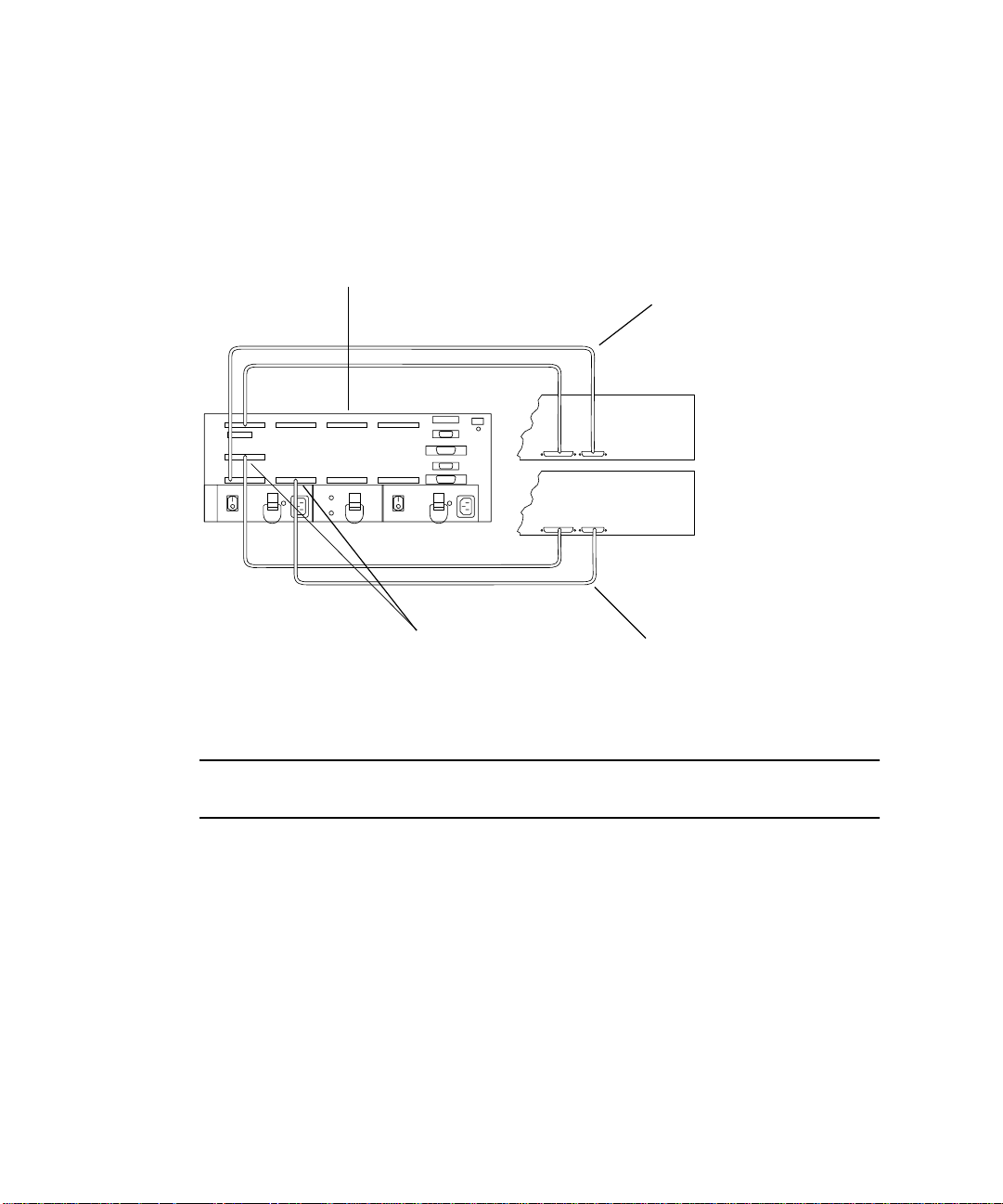
1.2.3 Independent Controller Module Connected to Two Hosts
FIGURE 1-3 shows one StorEdge A3500 controller module connected with SCSI cables
to two hosts.
StorEdge A3500 Controller Module
SCSI cables
Differential SCSI terminators
FIGURE 1-3 Independent Controller Module Connected to Two Hosts
Hosts
Chapter 1 SCSI Host Connections 1-5
Page 16
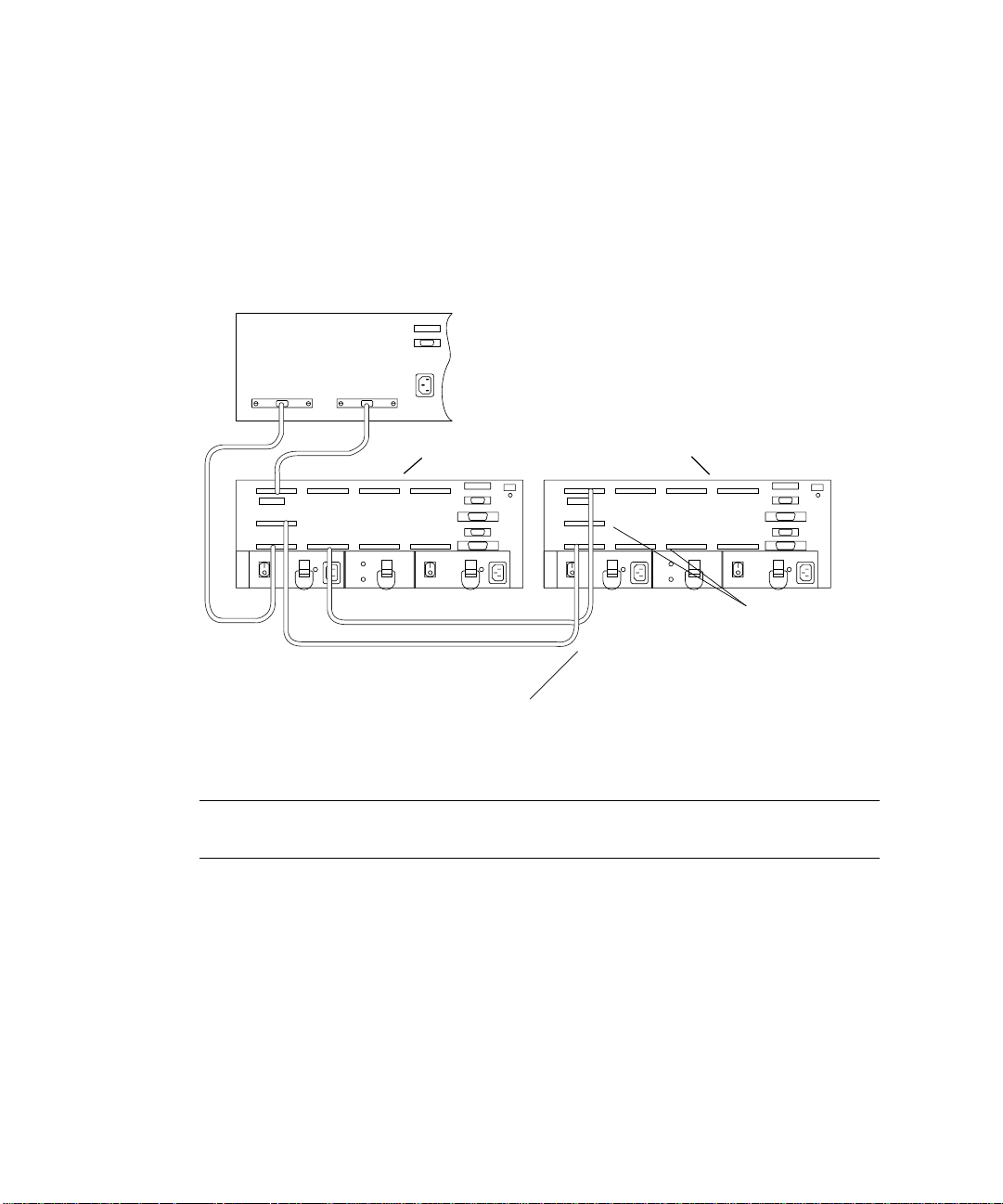
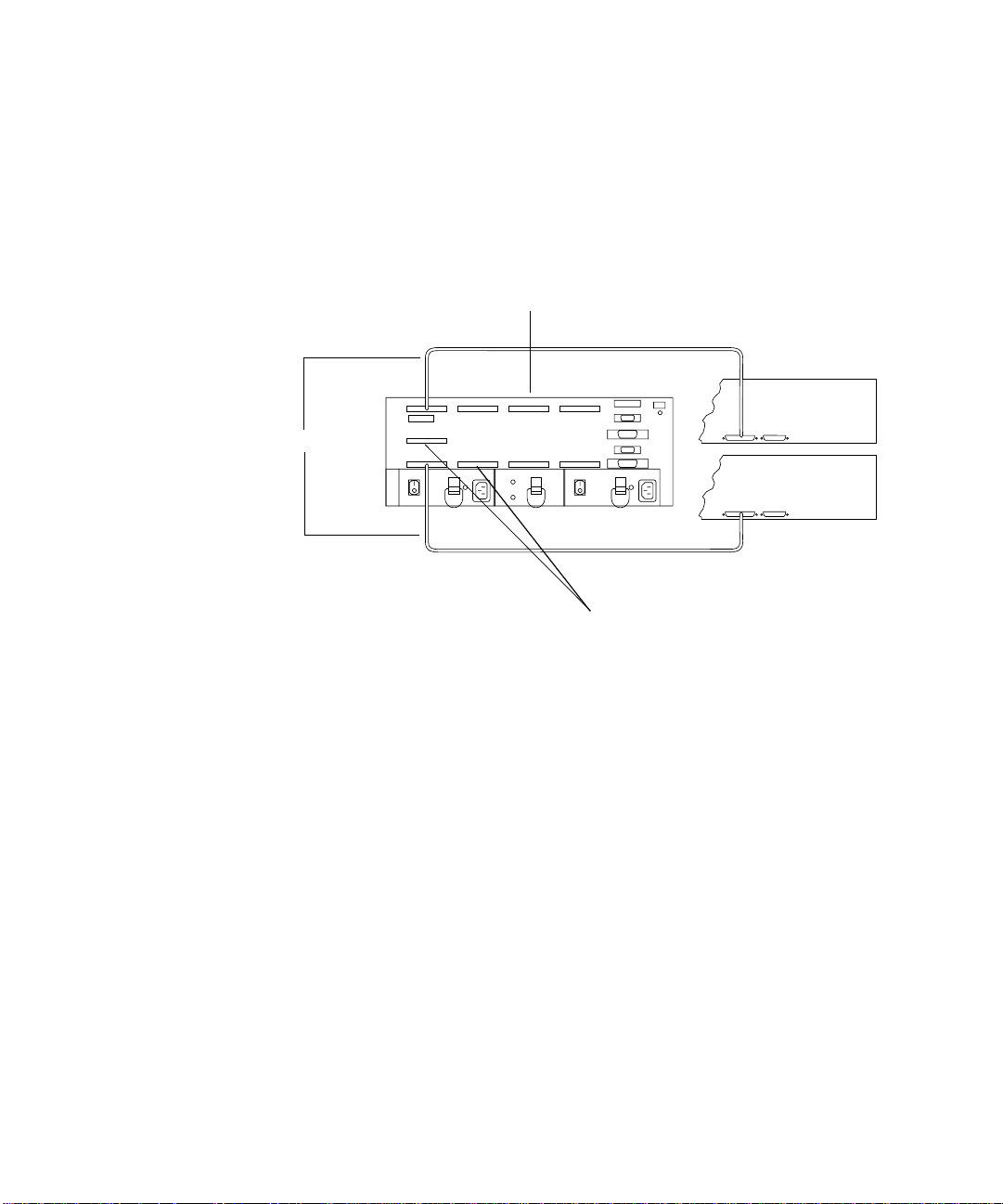
1.2.4 Multi-Host
FIGURE 1-4 shows a two-node multi-host configuration: one StorEdge A3500
controller module connected with SCSI cables to two hosts.
StorEdge A3500 Controller Module
SCSI cables
Hosts
Differential SCSI
terminators
FIGURE 1-4 Two-Node Multi-Host Configuration
SCSI cables
Note – The configuration shown in FIGURE 1-4 requires cluster software for
management.
For more information regarding the two-node multi-host configuration, such as
instructions for setting host SCSI IDs, refer to the Sun™ Cluster documentation that
is shipped with the host system.
For information about StorEdge A3500/A3500FC support for multi-host
configurations, refer to “Frequently Asked Questions” (FAQ) in the Sun StorEdge
RAID Manager 6.1.1 Release Notes (805-3656-xx) and in the Sun StorEdge RAID
Manager 6.22 Release Notes (805-7758-xx) and to the Sun StorEdge RAID Manager
User’s Guide.
1-6 Sun StorEdge A3500/A3500FC Hardware Configuration Guide • December 1999
Page 17
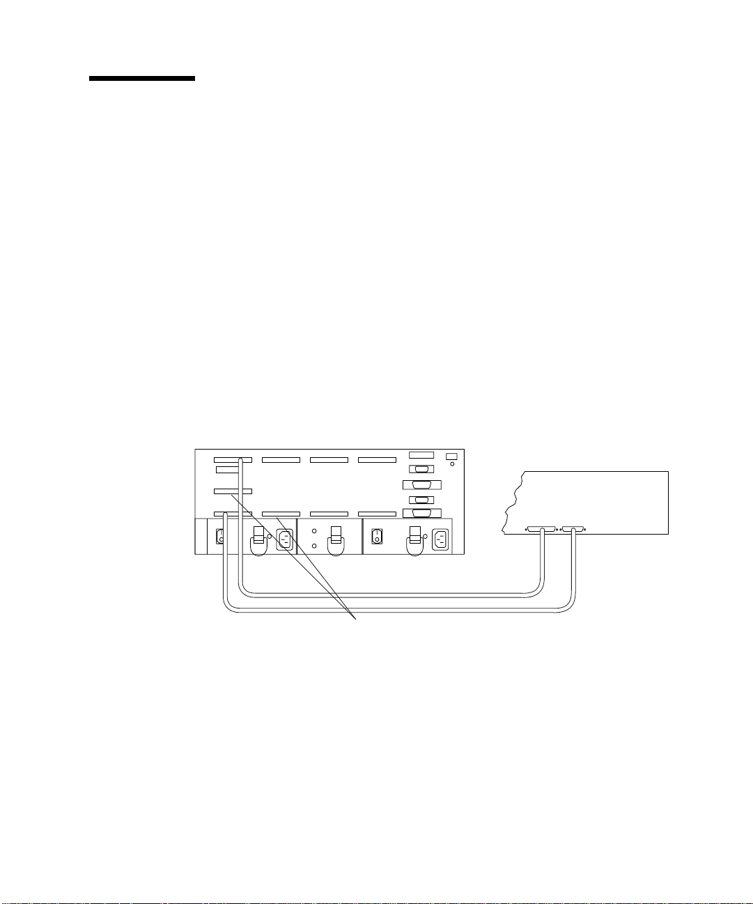
1.3 Ultra 2 Host System Power Connection Requirement
You can connect a controller module to an Ultra 2 host system; however, you must
connect the power cord of the Ultra 2 host to one of the AC power sequencers in the
expansion cabinet that contains the controller module.
Note – The RAID Manager 6.22 software does not support Ultra 2 host systems.
You need to order one of the following power cords depending on the type of power
sequencer in the expansion cabinet (
■ Ultra Enterprise™ expansion cabinet and StorEdge expansion cabinet—
part number 530-2197
■ 1422 mm/56-inch Data Center expansion cabinet—part number 180-1189 (United
States) or 180-1190 NEMA (European)
Caution – Failure to connect the power cord correctly as described here may cause
excessive ground current that could damage the system.
FIGURE 1-5):
Chapter 1 SCSI Host Connections 1-7
Page 18
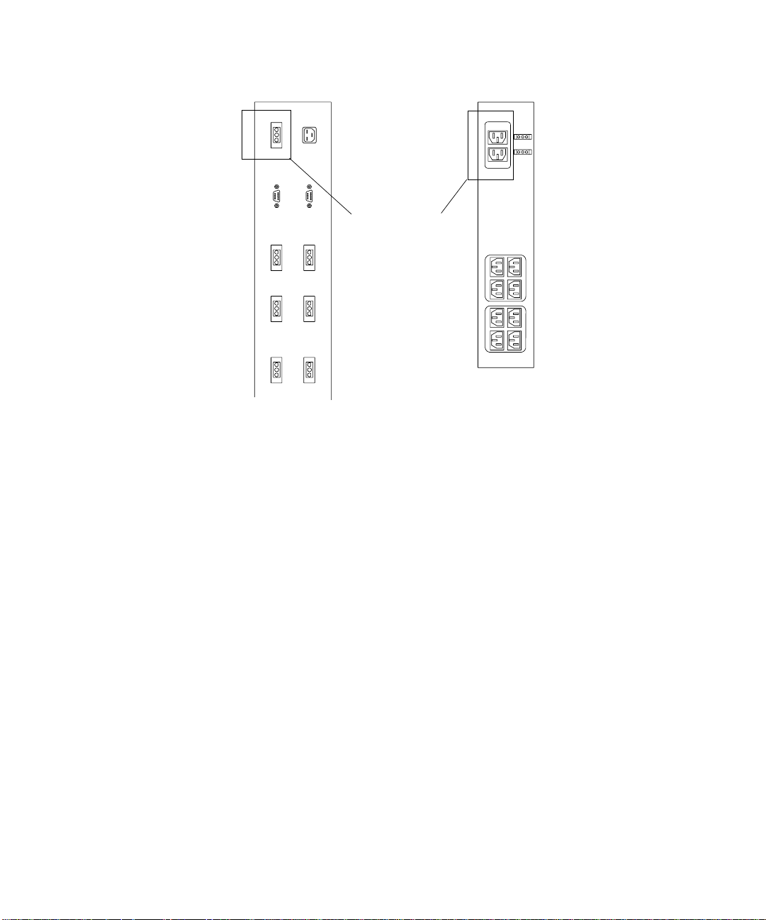
Ultra Enterprise
expansion cabinet
and StorEdge
expansion cabinet
power sequencer
FIGURE 1-5 AC Power Sequencers—Ultra 2 Power Connector
Connect Ultra 2
power cord here
1422 mm/56-inch
data center
expansioncabinet
power sequencer
To connect the power cord:
1. Gain access to the AC power sequencers.
See the documentation that came with the expansion cabinet.
2. Route the power cable from the Ultra 2 host under the expansion cabinet frame on
the same side as the power sequencer.
3. Connect the power cord from the Ultra 2 host into the top power connector of
either power sequencer (
FIGURE 1-5).
The power connectors are located on the other side of the power sequencer from the
main switch.
4. Reassemble the expansion cabinet.
See the documentation that you received with the expansion cabinet.
1-8 Sun StorEdge A3500/A3500FC Hardware Configuration Guide • December 1999
Page 19

CHAPTER
2
FC-AL Host Connections
This chapter describes configurations for one or two Fibre Channel-Arbitrated Loop
(FC-AL) Sun StorEdge A3500FC controller modules connected to one or more hosts.
The following topics are covered in this chapter:
■ Configuration Guidelines—page 2-2
■ Supported FC-AL Host Configurations—page 2-3
■ Single Host Connected to One Controller Module—page 2-4
■ Independent Controller Module Connected to Two Hosts—page 2-5
■ Single Host Connected to One Controller Module Using Hubs—page 2-6
■ Single Host Connected to Two Controller Modules Using Hubs—page 2-7
■ Single Host Connected to Four Controller Modules in a Loop Using Hubs—
page 2-9
■ Multi-Host—page 2-11
■ Setting the Loop ID—page 2-13
2-1
Page 20

2.1 Configuration Guidelines
Use the following guidelines to install and cable or reconfigure your StorEdge
A3500FC system.
Caution – The onboard SOC+ on the I/O board is not qualified yet to work with
the StorEdge A3500FC controller module.
Caution – At this time, only single port connection is qualified on the dual-ported
host bus adapter card.
■ The part number for the 15 meter FC-AL host cable is 595-3379-xx; the Marketing
part number is X978A.
■ Do not exceed a fiber-optic cable length of 500 meters (1640.5 feet).
■ Install 16-bit, differential terminators to both HOST IN connectors on the back of
the controller module (
Differential SCSI terminators—HOST IN
FIGURE 2-1).
FIGURE 2-1 Differential SCSI Terminators on Rear of Controller Module
2-2 Sun StorEdge A3500/A3500FC Hardware Configuration Guide • December 1999
Page 21

■ Once you finish cabling the devices and powering on, reboot the system by
typing boot -r at the ok prompt before beginning any SCSI bus activity.
■ Perform a system check to make sure that SCSI and fiber-optic cable connections
are secure. Check for fault LEDs on the hardware or error messages in the RAID
Manager GUI.
Note – Refer to your server and rack documentation for instructions on grounding
the StorEdge A3500FC expansion cabinet.
2.2 Supported FC-AL Host Configurations
The illustrations in this section show the FC-AL cable connections for the following
configurations:
■ Single Host Connected to One Controller Module
■ Independent Controller Module Connected to Two Hosts
■ Single Host Connected to One Controller Module Using Hubs
■ Single Host Connected to Two Controller Modules Using Hubs
■ Single Host Connected to Four Controller Modules in a Loop Using Hubs
■ Multi-Host
Chapter 2 FC-AL Host Connections 2-3
Page 22

2.2.1 Single Host Connected to One Controller Module
FIGURE 2-2 shows one host directly connected through fiber-optic cables to one
StorEdge A3500FC controller module.
Host
Host adapter
Host adapter
Fiber-optic cables
FIGURE 2-2 One Host Connected to One Controller Module
StorEdge A3500FC controller module
Controller A
FC-AL port
Controller B
FC-AL port
SCSI x 5
Drive tray x 5
2-4 Sun StorEdge A3500/A3500FC Hardware Configuration Guide • December 1999
Page 23

2.2.2 Independent Controller Module Connected to Two Hosts
FIGURE 2-3 shows one StorEdge A3500FC controller module connected through fibre-
optic cables to two hosts. Refer to the Sun StorEdge RAID Manager Installation and
Support Guide for instructions on setting up independent controller configurations in
the RAID Manager software.
Hosts
StorEdge A3500FC controller module
Host adapter
Host adapter
Fiber-optic cables
FIGURE 2-3 Independent Controller Module Connected to Two Hosts
Controller A
FC-AL port
Controller B
FC-AL port
Drive tray x 5
SCSI x 5
Chapter 2 FC-AL Host Connections 2-5
Page 24

2.2.3 Single Host Connected to One Controller Module Using Hubs
FIGURE 2-4 shows one host connected through fiber-optic cables to one StorEdge
A3500FC controller module using hubs.
Note – No other type of fibre channel device should share the same loop or hub
connected to the A3500FC controller module.
Host
Host adapter
Host adapter
Fiber-optic cables
FIGURE 2-4 Single Host Connected to One Controller Module Using Hubs
Hubs
StorEdge A3500FC controller module
Controller A
FC-AL port
Controller B
FC-AL port
Drive tray x 5
SCSI x 5
2-6 Sun StorEdge A3500/A3500FC Hardware Configuration Guide • December 1999
Page 25

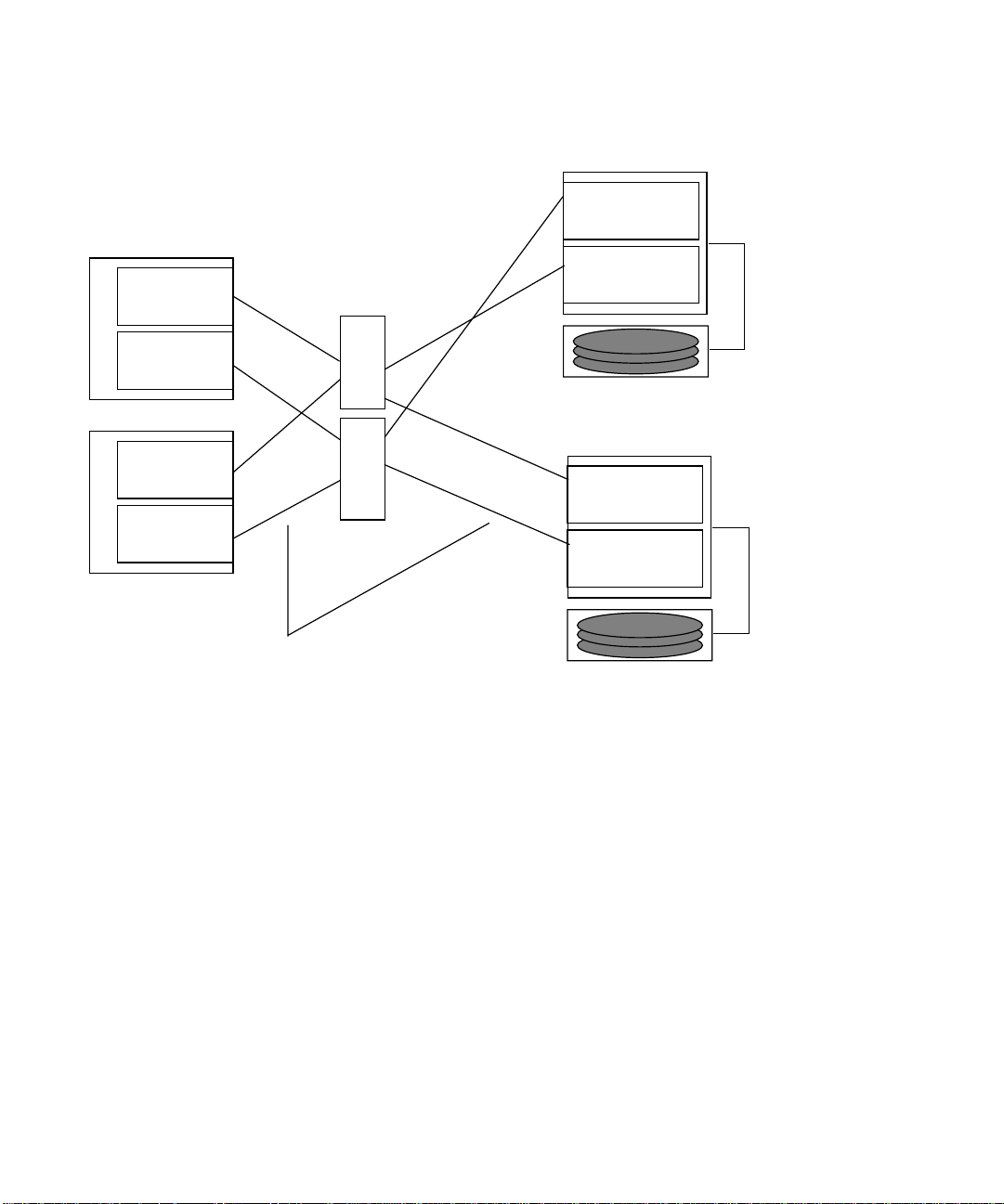
2.2.4 Single Host Connected to Two Controller Modules Using Hubs
FIGURE 2-5 shows one host connected through fiber-optic cables to two StorEdge
A3500FC controller modules using hubs. You can connect controller modules in the
same or separate cabinets.
Note – No other type of fibre channel device should share the same loop or hub
connected to the A3500FC controller module.
Each controller that is connected to a hub must have a unique loop ID. Whenever
you add a second controller to a hub, make sure that the loop ID of the controller
being connected is different from the loop ID of any other controller currently
connected to the same hub.
Refer to Section 2.3 “Setting the Loop ID” on page 2-13 for instructions on setting the
loop ID of a controller.
Caution – Ensure that the controller module IDs are set so that each hub is
connected to A and B controller canisters.
Chapter 2 FC-AL Host Connections 2-7
Page 26

StorEdge A3500FC controller module
Controller A
FC-AL port
Controller B
FC-AL port
SCSI x 5
Host
Host adapter
Host adapter
FIGURE 2-5 Single Host Connected to Two Controller Modules Using Hubs
Hubs
B
A
A
B
Fiber-optic cables
Drive tray x 5
StorEdge A3500FC controller module
Controller A
FC-AL port
Controller B
FC-AL port
SCSI x 5
Drive tray x 5
2-8 Sun StorEdge A3500/A3500FC Hardware Configuration Guide • December 1999
Page 27

2.2.5 Single Host Connected to Four Controller Modules in a Loop Using Hubs
FIGURE 2-6 shows an example of one host connected through fiber-optic cables to four
StorEdge A3500FC controller modules in a loop using hubs.
Note – No other type of fibre channel device should share the same loop or hub
connected to the A3500FC controller module.
Each controller that is connected to a hub must have a unique loop ID. Whenever
you add a second controller to a hub, make sure that the loop ID of the controller
being connected is different from the loop ID of any other controller currently
connected to the same hub.
Refer to Section 2.3 “Setting the Loop ID” on page 2-13 for instructions on setting the
loop ID of a controller.
Caution – Ensure that the controller module IDs are set so that each hub is
connected to A and B controller canisters.
Chapter 2 FC-AL Host Connections 2-9
Page 28

Host
Host adapter
Host adapter
Hubs
B
A
A
B
StorEdge A3500FC controller module
Controller A FC-AL port
Controller B FC-AL port
SCSI x 5
Drive tray x 5
StorEdge A3500FC controller module
Controller A FC-AL port
Controller B FC-AL port
SCSI x 5
Drive tray x 5
StorEdge A3500FC controller module
Controller A FC-AL port
Controller B FC-AL port
Drive tray x 5
StorEdge A3500FC controller module
Controller A FC-AL port
Fiber-optic cables
Controller B FC-AL port
Drive tray x 5
FIGURE 2-6 Single Host Connected to Four Controller Modules in a Loop Using Hubs
2-10 Sun StorEdge A3500/A3500FC Hardware Configuration Guide • December 1999
SCSI x 5
SCSI x 5
Page 29

2.2.6 Multi-Host
FIGURE 2-7 shows an example of a multi-host configuration: two hosts connected
through fiber-optic cables to two StorEdge A3500FC controller modules using hubs.
Note – No other type of fibre channel device should share the same loop or hub
connected to the A3500FC controller module.
Each controller that is connected to a hub must have a unique loop ID. Whenever
you add a second controller to a hub, make sure that the loop ID of the controller
being connected is different from the loop ID of any other controller currently
connected to the same hub.
Refer to Section 2.3 “Setting the Loop ID” on page 2-13 for instructions on setting the
loop ID of a controller.
Caution – Ensure that the controller module IDs are set so that each hub is
connected to A and B controller canisters.
Chapter 2 FC-AL Host Connections 2-11
Page 30
Host
Host adapter
Hubs
StorEdge A3500FC controller module
Controller A
FC-AL port
Controller B
FC-AL port
SCSI x 5
Host adapter
Host
Host adapter
Host adapter
FIGURE 2-7 Two Hosts Connected to Two Controller Modules Using Hubs
Fiber-optic cables
B
A
Drive tray x 5
StorEdge A3500FC controller module
A
B
Controller A
FC-AL port
Controller B
FC-AL port
SCSI x 5
Drive tray x 5
2-12 Sun StorEdge A3500/A3500FC Hardware Configuration Guide • December 1999
Page 31

2.3 Setting the Loop ID
This section explains how to set the loop ID of a controller that is connected to a
hub.
Tools and equipment needed:
■ Needlenose pliers
■ Jumpers (supplied with the StorEdge A3500/A3500FC unit)
■ Antistatic wrist strap
Every device attached to a SCSI or FC-AL bus must have a unique controller module
ID number in order to communicate. The factory default ID settings for controller A
and B are ID 5 and ID 4, respectively.
Note – Do not configure more than four controller modules on the same loop.
1. Locate the 16 pins on the rear of the FC-AL controller module (
FIGURE 2-8).
The eight pins on the right determine the host ID for controller 1(A); the pins on the
left determine the ID for controller 2(B).
2. Wearing the antistatic wrist strap, install jumpers on the pins as shown in
FIGURE 2-8.
If necessary, use the needlenose pliers to remove the jumpers.
Chapter 2 FC-AL Host Connections 2-13
Page 32

Controller B Controller A
Controller B Controller A
ID AL
8
4
2 1 Dec PA
15
16
8421 8421
1
2
842 1 Dec PA
0EF
1E8
2E4
3E2
4E1
5E0
6DC
7DA
8D9
9D6
10 D5
ID AL
0EF
1E8
2E4
3E2
4E1
5E0
6DC
7DA
8D9
9D6
10 D5
11 D4
12 D3
13 D2
14 D1
15 CE 15 CE
FIGURE 2-8 Controller Module FC-AL ID Settings
2-14 Sun StorEdge A3500/A3500FC Hardware Configuration Guide • December 1999
11 D4
12 D3
13 D2
14 D1
Page 33

CHAPTER
3
Sun StorEdge A3500/A3500FC Configurations
This chapter explains how to set up the following configurations:
■ 1x2—One controller module with two StorEdge D1000 disk arrays
■ 1x5—One controller module with five StorEdge D1000 disk arrays
■ 2x7—Two controller modules with seven StorEdge D1000 disk arrays
■ 3x15—Three controller modules with fifteen StorEdge D1000 disk arrays
The topics covered in this chapter are:
■ StorEdge D1000 Disk Array Settings—page 3-2
■ 1x2 Configuration—page 3-3
■ 1x5 Configuration—page 3-5
■ 2x7 Configuration—page 3-7
■ 3x15 Configuration—page 3-9
■ 1x2 Cables and Connections—page 3-11
■ Driveside SCSI Connections—page 3-11
■ Power Connections—page 3-13
■ 1x5 Cables and Connections—page 3-14
■ Driveside SCSI Connections—page 3-14
■ Power Connections—page 3-16
■ 2x7 Cables and Connections—page 3-17
■ SCSI Cable Lengths—page 3-18
■ Power Connections—page 3-19
■ 3x15 Cables and Connections—page 3-20
■ SCSI Cable Lengths—page 3-23
■ Connections Between Power Sequencers—page 3-25
■ Connections to AC Power Sources—page 3-25
■ Power Connections for Expansion Cabinets—page 3-26
3-1
Page 34

3.1 StorEdge D1000 Disk Array Settings
This section describes how to set attributes for the StorEdge D1000
disk arrays (
■ 1x2—One controller module with two StorEdge D1000 disk arrays
■ 1x5—One controller module with five StorEdge D1000 disk arrays
■ 2x7—Two controller modules with seven StorEdge D1000 disk arrays
■ 3x15—Three controller modules with fifteen StorEdge D1000 disk arrays
For the D1000 disk arrays, you must set the following attributes:
■ Option switch
■ Module ID
■ SCSI jumper cables and terminators
FIGURE 3-1) in the following configurations:
Option switch
Module ID
IN/OUT-1 IN/OUT-1
Rear
FIGURE 3-1 StorEdge D1000 Disk Array
IN/OUT -2
IN/OUT -2
3-2 Sun StorEdge A3500/A3500FC Hardware Configuration Guide • December 1999
Page 35

3.1.1 1x2 Configuration
The 1x2 configuration includes one controller module with two StorEdge D1000 disk
arrays.
Note – The 1x2 configuration is not qualified on the A3500FC controller module.
3.1.1.1 Option Switch
Both disk arrays have split buses. Their option switches should be set as shown in
FIGURE 3-2.
53124
FIGURE 3-2 1x2 Option Switch Settings for StorEdge D1000 Disk Array
This setting will cause the disk drives in the StorEdge D1000 disk arrays to be
numbered as shown in
FIGURE 3-3 and FIGURE 3-4.
123 01 230
FIGURE 3-3 8-Drive StorEdge D1000 SCSI ID (Split Bus)
Chapter 3 Sun StorEdge A3500/A3500FC Configurations 3-3
Page 36

123 012304545
FIGURE 3-4 12-Drive StorEdge D1000 SCSI Disk ID (Split Bus)
3.1.1.2 Module ID Switch
Ensure that the module IDs for the StorEdge D1000 disk arrays are set according to
TABLE 3-1.
TABLE3-1 1x2 Module ID Switch Settings
Disk array number Module ID setting
2 (Top) 2
1 (Bottom) 1
Note – Since the top and bottom disk arrays are split between one controller
module, the Module IDs will overlap. This may result in error messages while the
host system is booting. The ASC/ASCQ codes for this error is 98/01, and the Sense
Key is 6. These error messages are information only and will not impact system
performance.
3.1.1.3 SCSI Jumper Cables and Terminators
The StorEdge D1000 disk arrays should have differential SCSI terminators on the
inside IN/OUT-1 and IN/OUT-2 SCSI connectors. This configuration is shown in
FIGURE 3-11.
3-4 Sun StorEdge A3500/A3500FC Hardware Configuration Guide • December 1999
Page 37

3.1.2 1x5 Configuration
The 1x5 configuration includes one controller module with five StorEdge D1000 disk
arrays.
3.1.2.1 Option Switch
All StorEdge D1000 disk arrays in this configuration should have their option
switches set as shown in
53124
FIGURE 3-5 1x5 Option Switch Settings for StorEdge D1000 Disk Array
This will cause the disk drives in the StorEdge D1000 disk arrays to be numbered as
shown in
FIGURE 3-6 and FIGURE 3-7.
FIGURE 3-5.
123 8910110
FIGURE 3-6 8-Drive StorEdge D1000 SCSI ID (Single Bus)
123 8910110121345
FIGURE 3-7 12-Drive StorEdge D1000 SCSI ID (Single Bus)
Chapter 3 Sun StorEdge A3500/A3500FC Configurations 3-5
Page 38

3.1.2.2 Module ID Switch
Ensure that the module IDs for the StorEdge D1000 disk arrays are set according to
TABLE 3-2.
TABLE3-2 1x5 Module ID Switch Settings
Disk Array Number Module ID Setting
5 (Top) 5
44
33
22
1 (Bottom) 1
3.1.2.3 SCSI Jumper Cables and Terminators
All Sun StorEdge D1000 disk arrays in this configuration should have SCSI jumper
cables between the middle SCSI connectors (IN/OUT-1 and IN/OUT-2) and a
differential SCSI terminator in the far right SCSI connector (IN/OUT-2). This
configuration is shown in
FIGURE 3-15.
3-6 Sun StorEdge A3500/A3500FC Hardware Configuration Guide • December 1999
Page 39

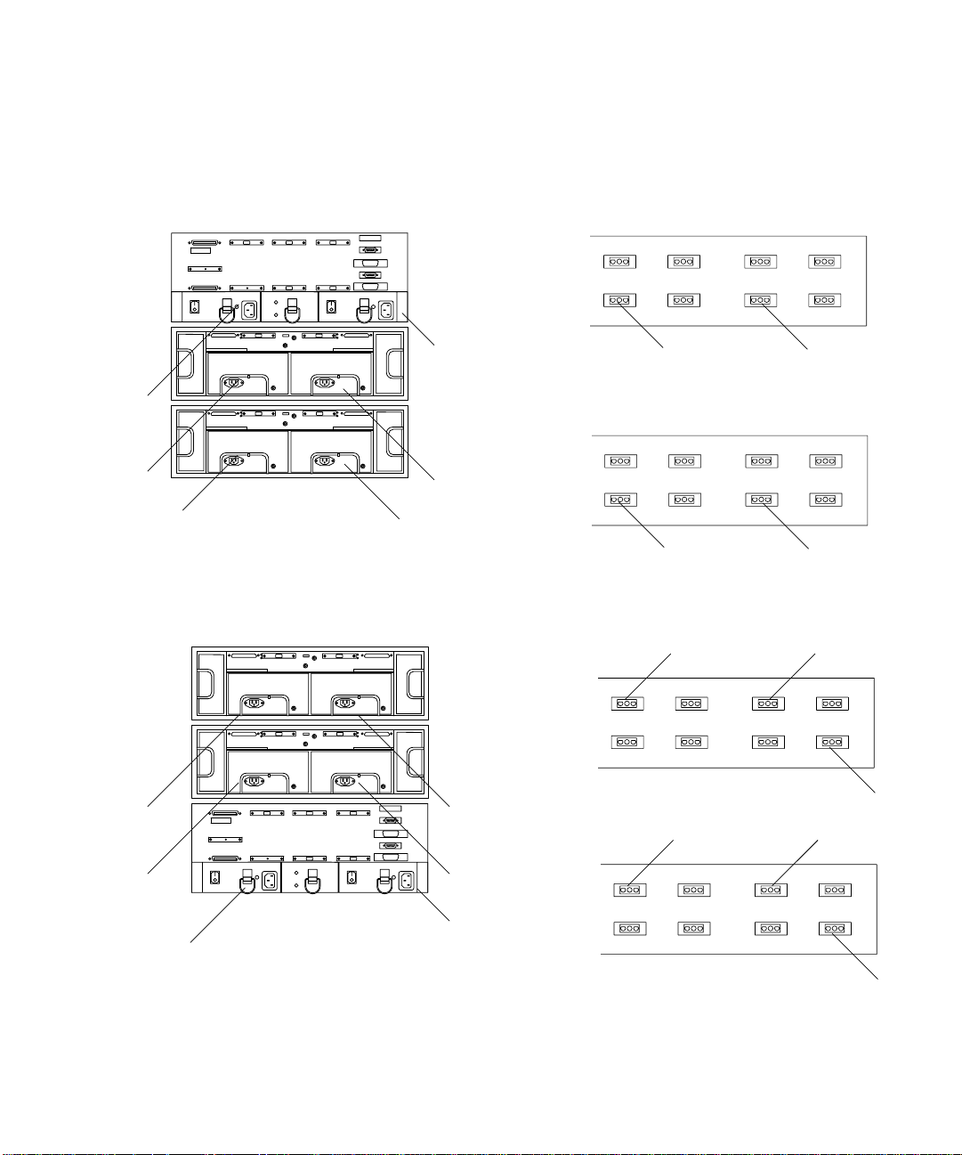
3.1.3 2x7 Configuration
The 2x7 configuration includes two controller modules with seven StorEdge D1000
disk arrays.
3.1.3.1 Option Switch
In FIGURE 3-17, the disk drives in each of the top four disk arrays are on a single bus
and should be set as described in Section 3.1.2.1 “Option Switch” on page 3-5. The
bottom three disk arrays have split buses. Their option switches should be set as
shown in
53124
FIGURE 3-8 2x7 Option Switch Settings for StorEdge D1000 Disk Array
This will cause the disk drives in the StorEdge D1000 disk arrays to be numbered as
shown in
FIGURE 3-8.
FIGURE 3-9 and FIGURE 3-10.
123 01 230
FIGURE 3-9 8-Drive StorEdge D1000 SCSI ID (Split Bus)
123 012304545
FIGURE 3-10 12-Drive StorEdge D1000 SCSI Disk ID (Split Bus)
Chapter 3 Sun StorEdge A3500/A3500FC Configurations 3-7
Page 40

3.1.3.2 Module ID Switch
Ensure that the module IDs for the StorEdge D1000 disk arrays are set according to
TABLE 3-3.
TABLE3-3 2x7 Module ID Switch Settings
Disk Array Number Module ID Setting
7 (Top) 5
64
55
44
33
22
1 (Bottom) 1
In this configuration (from the front of the expansion cabinet), the following occurs:
■ Controller module A controls the right side of disk arrays 1 through 3 and all of
disk arrays 4 and 5.
■ Controller module B controls the left side of disk arrays 1 through 3 and all of
disk arrays 6 and 7.
This configuration is shown in
FIGURE 3-17.
3.1.3.3 SCSI Jumper Cables and Terminators
The top four StorEdge D1000 disk arrays should have SCSI jumper cables between
the middle SCSI connectors (IN/OUT-1 and IN/OUT-2) and a differential SCSI
terminator in the far right SCSI connector (IN/OUT-2).
The bottom three StorEdge D1000 disk arrays should have differential SCSI
terminators on the inside IN/OUT-1 and IN/OUT-2 SCSI connectors. This
configuration is shown in
3-8 Sun StorEdge A3500/A3500FC Hardware Configuration Guide • December 1999
FIGURE 3-17.
Page 41

3.1.4 3x15 Configuration
The 3x15 configuration includes three controller modules with a total of fifteen
StorEdge D1000 disk arrays combined in a 2x7 cabinet or a 1x8 cabinet.
3.1.4.1 Option Switch
All disk arrays are on a single bus and should be set as described in Section 3.1.2.1
“Option Switch” on page 3-5.
3.1.4.2 Module ID Switch
Ensure that the module IDs for the StorEdge D1000 disk arrays are set according to
TABLE 3-4 and TABLE 3-5.
TABLE3-4 3x15 Module ID Switch Settings in the 2x7 Cabinet
Disk Array Number Module ID Setting
7 (Top) 5
64
53
42
31
21
1 (Bottom) 2
TABLE3-5 3x15 Module ID Switch Settings in the 1x8 Cabinet
Disk Array Number Module ID Setting
8 (Top) 5
74
63
52
41
35
24
1 (Bottom) 3
Chapter 3 Sun StorEdge A3500/A3500FC Configurations 3-9
Page 42

In this configuration (from the front of the expansion cabinet), the following occurs:
■ Controller module A controls disk arrays 1 and 2 in the 2x7 cabinet and disk
arrays 1 through 3 in the 1x8 cabinet (
■ Controller module B controls disk arrays 3 through 7 in the 2x7 cabinet
(
FIGURE 3-20).
■ Controller module C controls disk arrays 4 through 8 in the 1x8 cabinet
(
FIGURE 3-21).
FIGURE 3-19).
3.1.4.3 SCSI Jumper Cables and Terminators
All StorEdge D1000 disk arrays in this configuration should have SCSI jumper cables
between the middle SCSI connectors (IN/OUT-1 and IN/OUT-2) and a differential
SCSI terminator in the far right SCSI connector (IN/OUT-2).
3-10 Sun StorEdge A3500/A3500FC Hardware Configuration Guide • December 1999
Page 43

3.2 1x2 Cables and Connections
This section contains information about SCSI and power connections for one
StorEdge A3500 with two StorEdge D1000 disk arrays.
Note – The 1x2 configuration is not qualified on the A3500FC controller module.
In the 1x2 configuration, the controller module can be either on top of or below the
two disk arrays. Both configurations are described in this section.
Tip – Do not place the controller module at the bottom of the rack because the
controller board diagnostic LEDs will not be visible.
3.2.1 Driveside SCSI Connections
The following table shows the length of each SCSI cable connected to the drive
connections on the controller module.
TABLE3-6 Controller Module A (1x2) Cables
SCSI Port Number Cable Length Part Number
1 0.8m/2.6 ft 530-1884
2 0.8m/2.6 ft 530-1884
3 0.8m/2.6 ft 530-1884
4 0.8m/2.6 ft 530-1884
5 Differential SCSI terminator 150-1890
The inboard IN/OUT connectors on each disk array are terminated with a
differential SCSI terminator, part number 150-1890.
FIGURE 3-11 and FIGURE 3-12 show the SCSI connections between the StorEdge A3500
controller module and the two StorEdge D1000 disk arrays.
Chapter 3 Sun StorEdge A3500/A3500FC Configurations 3-11
Page 44

SCS
2
1
Differential SCSI
terminator
Differential
terminator
Differential SCSI
terminator
I
FIGURE 3-11 One StorEdge A3500 Controller Module and Two StorEdge D1000
Disk Arrays (SCSI)
Differential SCSI
terminator
Differential SCSI
terminator
2
1
Differential SCSI
terminator
FIGURE 3-12 Two StorEdge D1000 Disk Arrays and One StorEdge A3500
Controller Module (SCSI)
3-12 Sun StorEdge A3500/A3500FC Hardware Configuration Guide • December 1999
Page 45
3.2.2 Power Connections
Because the controller module must receive power after the disk arrays, connect the
disk arrays to the first stage of the power sequencer and the controller module to the
second. Two examples are shown in
FIGURE 3-13 and FIGURE 3-14.
Front
sequencer
L3
L2
L6
L1
R3
Rear
R2
Rear view
FIGURE 3-13 One StorEdge A3500 Controller Module and Two StorEdge D1000
Disk Arrays (Power)
R1
R6
sequencer
Front
sequencer
R1&R2
L1&L2
R6 R4
L6 L4
R3
L3
R5
L5
L4
R5
Rear view
FIGURE 3-14 Two StorEdge D1000 Disk Arrays and One StorEdge A3500
Controller Module (Power)
R4
Chapter 3 Sun StorEdge A3500/A3500FC Configurations 3-13
Rear
sequencer
L5
Page 46

3.3 1x5 Cables and Connections
This section contains information about SCSI, FC-AL, and power connections for one
StorEdge A3500, or one StorEdge A3500FC controller module, with five StorEdge
D1000 disk arrays.
3.3.1 Driveside SCSI Connections
The following table shows the lengths of each SCSI cable connected to the drive
connections on the controller module.
TABLE3-7 Controller Module A (1x5) Cables
SCSI Port Number Cable Length Part Number
1 2.0m/6.5 ft 530-1885
2 2.0m/6.5 ft 530-1885
3 2.0m/6.5 ft 530-1885
4 2.0m/6.5 ft 530-1885
5 2.0m/6.5 ft 530-1885
The inboard IN/OUT connectors on each of the disk arrays are connected using a
0.2m/0.65 ft SCSI jumper cable, part number 530-1883.
The outboard IN/OUT-2 connector on each disk array is terminated with a
differential SCSI terminator, part number 150-1890.
FIGURE 3-15 shows the SCSI connections between the A3500 controller module and
the five D1000 disk arrays.
3-14 Sun StorEdge A3500/A3500FC Hardware Configuration Guide • December 1999
Page 47

5
4
3
2
Differential SCSI
1
terminator
SCSI jumper cable
FIGURE 3-15 One StorEdge A3500 Controller Module and Five StorEdge D1000
Disk Arrays (SCSI)
Chapter 3 Sun StorEdge A3500/A3500FC Configurations 3-15
Page 48

3.3.2 Power Connections
FIGURE 3-16 shows the power connections for 1x5 configurations.
R5
L5
L6
R6
L4
R4
L3
R3
L2
R2
Front
sequencer
L1
3-16 Sun StorEdge A3500/A3500FC Hardware Configuration Guide • December 1999
Rear view
FIGURE 3-16 One StorEdge A3500 or A3500FC Controller Module and Five StorEdge
D1000 Disk Arrays (Power)
R1
Rear
sequencer
R6 R4
R1&R2 R3
L6 L4
L1&L2 L3
R5
L5
Page 49

3.4 2x7 Cables and Connections
This section contains information about SCSI, FC-AL, and power connections for
two StorEdge A3500 controller modules, or two StorEdge A3500FC controller
modules, with seven StorEdge D1000 disk arrays.
3.4.1 SCSI Cable Lengths
The following tables show the lengths of each SCSI cable connected to the drive
connections on the respective controller modules.
TABLE3-8 Controller Module A (2x7) Cables
SCSI Port Number Cable Length Part Number
1 0.8m/2.6 ft 530-1884
2 0.8m/2.6 ft 530-1884
3 0.8m/2.6 ft 530-1884
4 2.0m/6.5 ft 530-1885
5 2.0m/6.5 ft 530-1885
TABLE3-9 Controller Module B (2x7)
SCSI Port Number Cable Length Part Number
1 2.0m/6.5 ft 530-1885
2 0.8m/2.6 ft 530-1884
3 0.8m/2.6 ft 530-1884
4 2.0m/6.5 ft 530-1885
5 2.0m/6.5 ft 530-1885
The inboard IN/OUT connectors on each of the top four disk arrays are connected
using a 0.2m/0.65 ft SCSI jumper cable, part number 530-1883.
The inboard IN/OUT connectors on the bottom three disk arrays are terminated
with differential SCSI terminators, part number 150-1890.
Chapter 3 Sun StorEdge A3500/A3500FC Configurations 3-17
Page 50

A5
A4
FIGURE 3-17 shows the SCSI connections between the two StorEdge A3500 controller
modules and the seven
StorEdge D1000 disk arrays.
B5
B4
Differential SCSI
terminator
SCSI jumper cable
A3
A2
A1
Controller Module A
FIGURE 3-17 Two StorEdge A3500 Controller Modules and Seven StorEdge D1000
Differential SCSI
terminators
Controller Module B
Disk Arrays (SCSI)
3-18 Sun StorEdge A3500/A3500FC Hardware Configuration Guide • December 1999
B3
B2
B1
Page 51

3.4.2 Power Connections
FIGURE 3-16 shows the power connections for 2x7 configurations.
L9
L8
L7
L6
L5
L3
L4
R9
R8
R7
R6
R5
R4
R3
Front
sequencer
R6 R4 R9
R1&R2
L6 L4 L9
R8
R7
L8
R3
R5
L2
R2
Rear viewL1
FIGURE 3-18 Two StorEdge A3500 or A3500FC Controller Modules and Seven StorEdge
R1
D1000 Disk Arrays (Power)
Rear
sequencer
L1&L2
Chapter 3 Sun StorEdge A3500/A3500FC Configurations 3-19
L7
L3
L5
Page 52

3.5 3x15 Cables and Connections
This section contains information about SCSI, FC-AL, and power connections for
three StorEdge A3500 controller modules, or three StorEdge A3500FC controller
modules, with fifteen StorEdge D1000 disk arrays in either the 2x7 StorEdge
expansion cabinet or the 1x8 StorEdge expansion cabinet.
Caution – The components in the expansion cabinets are configured as a single
unit. Make sure that the serial numbers on each expansion cabinet match.
3.5.1 SCSI Cable Lengths
The following tables show the lengths of each SCSI cable connected to the drive
connections on the respective controller modules.
TABLE3-10 Controller Module A (3x15 Configuration) Cables
SCSI Port Number Cable Length Part Number
1 0.8m/2.6 ft 530-1884
2 0.8m/2.6 ft 530-1884
3 4.0m/13.1 ft 530-2352
4 4.0m/13.1 ft 530-2352
5 4.0m/13.1 ft 530-2352
TABLE3-11 Controller Module B (3x15 Configuration) Cables
SCSI Port Number Cable Length Part Number
1 0.8m/2.6 ft 530-1884
2 0.8m/2.6 ft 530-1884
3 2.0m/6.5 ft 530-1885
4 2.0m/6.5 ft 530-1885
5 2.0m/6.5 ft 530-1885
3-20 Sun StorEdge A3500/A3500FC Hardware Configuration Guide • December 1999
Page 53

TABLE3-12 Controller Module C (3x15 Configuration) Cables
SCSI Port Number Cable Length Part Number
1 0.8m/2.6 ft 530-1884
2 0.8m/2.6 ft 530-1884
3 2.0m/6.5 ft 530-1885
4 2.0m/6.5 ft 530-1885
5 2.0m/6.5 ft 530-1885
The inboard IN/OUT connectors on each of the disk arrays are connected using a
0.2m/0.65 ft SCSI jumper cable, part number 530-1883.
The outboard IN/OUT-2 connector on each disk array is terminated with a
differential SCSI terminator, part number 150-1890.
Chapter 3 Sun StorEdge A3500/A3500FC Configurations 3-21
Page 54

FIGURE 3-19 shows the SCSI connections for controller module A.
Differential SCSI
A1
terminator
SCSI jumper cable
A2
3-22 Sun StorEdge A3500/A3500FC Hardware Configuration Guide • December 1999
2x7
FIGURE 3-19 Controller Module A—3x15 Configuration
1x8
A5
A4
A3
Page 55

B5
FIGURE 3-20 shows the SCSI connections for controller module B.
B4
B3
B2
B1
Differential SCSI
terminator
SCSI jumper cable
2x7
FIGURE 3-20 Controller Module B—3x15 Configuration
Chapter 3 Sun StorEdge A3500/A3500FC Configurations 3-23
1x8
Page 56

FIGURE 3-21 shows the SCSI connections for controller module C.
C5
SCSI jumper cable
Differential SCSI
terminator
C4
C3
C2
C1
2x7
FIGURE 3-21 Controller Module C—3x15 Configuration
3-24 Sun StorEdge A3500/A3500FC Hardware Configuration Guide • December 1999
1x8
Page 57

3.5.2 Connections Between Power Sequencers
The front and rear power sequencers in the 2x7 expansion cabinet and the 1x8
expansion cabinet must be interconnected. Make sure an interconnect cable (part
number 530-2325) is connected between the OUT on the front sequencer in the 2x7
expansion cabinet and the IN on the front sequencer in the 1x8 expansion cabinet
(
FIGURE 3-22). Make sure that the rear sequencers are likewise connected.
Out
In
FIGURE 3-22 Connecting the Power Sequencers
3.5.3 Connections to AC Power Sources
Each of the AC power cords connected to the expansion cabinets should be on
independent circuit breakers.
To ensure proper redundancy, if independent circuit breaker boxes or AC power
sources are used, make sure that power cords from the same expansion cabinet are
connected to different circuit breaker boxes or AC power sources.
Caution – Ensure that the second rack will not lose power before the first rack loses
power. Data loss is likely to occur if this happens. Do not configure the 3x15
expansion cabinets as shown in
electrician if you do not understand the schematics in these figures.
FIGURE 3-23 and FIGURE 3-24. Consult with an
Chapter 3 Sun StorEdge A3500/A3500FC Configurations 3-25
Page 58
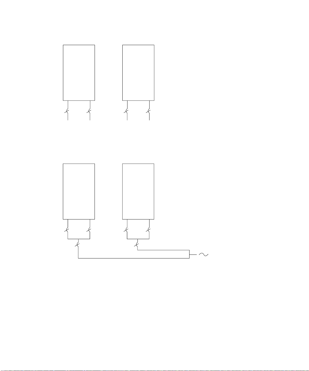
2x7
1x8
Phase A
FIGURE 3-23 Power Connections to Avoid (Different Phases)
2x7
FIGURE 3-24 Power Connections to Avoid (Same Phase)
Phase B
1x8
Same phase AC
3.5.4 Power Connections for Expansion Cabinets
The power connections for the 2x7 expansion cabinet are the same as those in the
standard 2x7 expansion cabinet (
3-26 Sun StorEdge A3500/A3500FC Hardware Configuration Guide • December 1999
FIGURE 3-18).
Page 59

The power connections for the 1x8 expansion cabinet are shown in FIGURE 3-25.
L9
L8
L7
L6
L5
L3
L4
R9
R8
R7
R6
R5
R4
R3
Front
sequencer
R6 R4 R9
R1&R2
L6 L4 L9
R3
R7
L3
R8
R5
L2
L1
R2
R1
Rear
sequencer
Rear view
L1&L2
FIGURE 3-25 One StorEdge A3500 or A3500FC Controller Module and Eight StorEdge
L7
L8
D1000 Disk Arrays (Power)
Chapter 3 Sun StorEdge A3500/A3500FC Configurations 3-27
L5
Page 60

3-28 Sun StorEdge A3500/A3500FC Hardware Configuration Guide • December 1999
Page 61

APPENDIX
A
Sun StorEdge A3500 and A3500FC Specifications
A.1 Initial Cold Start Surge Current
Specifications
The following tables provide the initial cold start surge specifications for the
StorEdge A3500 and A3500FC systems.
TABLEA-1 Device Surge Current Specifications
Device Specification for Each Power Supply
StorEdge A3x00 controller module 25A rms or 35A peak for one line cycle
™ disk array 15A rms or 21A peak for one line cycle
RSM
StorEdge D1000 disk array 11A rms or 22A peak for one line cycle
A-1
Page 62

TABLEA-2 Cabinet Surge Current Specifications
Device Specification for Each Power Cord
StorEdge A3000 (StorEdge A3000 controller module with RSM disk arrays
in 1422mm/56-in. cabinet):
1x5 configuration 120A rms or 169A peak for one line cycle
StorEdge A3500 (StorEdge A3000 controller with StorEdge D1000 disk arrays
in 1828mm/72-in. cabinet):
1x5 configuration 44A rms or 88A peak for one line cycle
2x7 configuration 72A rms or 114A peak for one line cycle
1x8 configuration 55A rms or 110A peak for one line cycle
A-2 Sun StorEdge A3500/A3500FC Hardware Configuration Guide • December 1999
 Loading...