

Page 1

Sun StorEdge™Network
FC Switch-8 and Switch-16
Installation and Configuration Guide
Sun StorEdge SAN 3.0 Release
Sun Microsystems, Inc.
901 San Antonio Road
Palo Alto, CA 94303
U.S.A. 650-960-1300
Part No. 816-0830-12
October 2001, Revision A
Send comments about this document to: docfeedback@sun.com
Page 2
Copyright 2001Sun Microsystems, Inc.,901 SanAntonio Road,Palo Alto,CA 94303-4900U.S.A. Allrights reserved.
This product ordocument isdistributed underlicenses restrictingits use,copying, distribution,and decompilation.No partof thisproduct or
document may be reproduced inany formby anymeans withoutprior writtenauthorization ofSun andits licensors,if any.Third-party
software,including fonttechnology,is copyrighted and licensed fromSun suppliers.
Parts of the product maybe derivedfrom BerkeleyBSD systems,licensed fromthe University of California. UNIX is a registered trademarkin
the U.S. and other countries, exclusively licensed through X/OpenCompany,Ltd.
Sun, Sun Microsystems,the Sunlogo, AnswerBook2,docs.sun.com, SunStorEdge, SunEnterprise, Java,Solstice DiskSuite,Solstice Backup,
StorTools, JDK, and Solaris aretrademarks, registeredtrademarks, or service marks of Sun Microsystems, Inc. inthe U.S.and othercountries.
All SPARCtrademarks areused underlicense andare trademarks or registered trademarksof SPARCInternational, Inc.in theU.S. andother
countries. Products bearingSPARCtrademarks arebased upon an architecture developedby SunMicrosystems, Inc.The EnergyStar logo is a
registeredtrademark ofEPA.
The OPEN LOOK and Sun™ Graphical User Interface was developed bySun Microsystems,Inc. forits usersand licensees.Sun acknowledges
the pioneering effortsof Xeroxin researchingand developing the concept of visual orgraphical userinterfaces forthe computerindustry.Sun
holds a non-exclusive license fromXerox tothe XeroxGraphical User Interface, which license also covers Sun’s licensees who implement OPEN
LOOK GUIs and otherwise comply with Sun’s written license agreements.
As an Energy Star partner, Sun Microsystems, Inc. has determined that configurations of this
product that bear the Energy Star Logo meet the Energy Star guidelines for energy efficiency.
Federal Acquisitions: CommercialSoftware—Government UsersSubject toStandard License TermsandConditions.
DOCUMENTATION IS PROVIDED “AS IS” AND ALL EXPRESS OR IMPLIED CONDITIONS, REPRESENTATIONS AND WARRANTIES,
INCLUDING ANY IMPLIED WARRANTYOF MERCHANTABILITY,FITNESS FOR A PARTICULARPURPOSE OR NON-INFRINGEMENT,
ARE DISCLAIMED, EXCEPT TO THE EXTENT THAT SUCH DISCLAIMERS ARE HELD TO BE LEGALLY INVALID.
Copyright 2001 Sun Microsystems, Inc.,901 SanAntonio Road,Palo Alto,CA 94303-4900Etats-Unis. Tousdroits réservés.
Ce produit oudocument estdistribué avecdes licencesqui enrestreignent l’utilisation, la copie, la distribution, et la décompilation. Aucune
partie de ce produit oudocument nepeut êtrereproduitesous aucuneforme, parquelque moyenque cesoit, sansl’autorisation préalableet
écrite de Sun et de ses bailleurs de licence, s’il y en a.Le logicieldétenu pardes tiers,et quicomprend latechnologie relativeaux policesde
caractères,est protégépar uncopyright etlicencié pardes fournisseursde Sun.
Des parties de ce produitpourront êtredérivées des systèmes Berkeley BSD licenciés par l’Université de Californie. UNIX est une marque
déposée aux Etats-Unis et dans d’autres payset licenciéeexclusivement parX/Open Company,Ltd.
Sun, Sun Microsystems,le logoSun, AnswerBook2,docs.sun.com,Sun StorEdge,Sun Enterprise,Java, SolsticeDiskSuite, SolsticeBackup,
StorTools, JDK, et Solaris sont des marquesde fabriqueou desmarques déposées,ou marquesde service, de Sun Microsystems,Inc. auxEtatsUnis et dans d’autres pays.Toutesles marquesSPARCsontutilisées souslicence etsont desmarques defabrique oudes marquesdéposées de
SPARC International, Inc. aux Etats-Unis et dans d’autres pays.Les produitsportant lesmarques SPARC sont baséssur unearchitecture
développée par Sun Microsystems, Inc.
L’interfaced’utilisation graphique OPEN LOOK et Sun™ a été développéepar SunMicrosystems, Inc.pour sesutilisateurs etlicenciés. Sun
reconnaîtles effortsde pionniersde Xeroxpour la rechercheet ledéveloppement duconcept desinterfaces d’utilisationvisuelle ougraphique
pour l’industrie de l’informatique. Sun détient une licence non exclusive deXerox surl’interface d’utilisationgraphique Xerox,cette licence
couvrant également les licenciés de Sun qui mettent en place l’interfaced’utilisation graphiqueOPEN LOOKet quien outrese conformentaux
licences écrites de Sun.
LA DOCUMENTATIONEST FOURNIE “EN L’ETAT” ET TOUTESAUTRES CONDITIONS, DECLARATIONS ET GARANTIES EXPRESSES
OU TACITES SONT FORMELLEMENTEXCLUES, DANSLA MESUREAUTORISEE PARLA LOIAPPLICABLE, YCOMPRIS NOTAMMENT
TOUTE GARANTIE IMPLICITE RELATIVE A LA QUALITE MARCHANDE, A L’APTITUDE A UNE UTILISATION PARTICULIERE OU A
L’ABSENCE DE CONTREFAÇON.
Please
Recycle
Page 3

Declaration of Conformity
Compliance Model Number: Compliance ID
Product Name: Sun StorEdge network FC
EMC
European Union
This equipment complies with the following requirements of the EMC Directive 89/336/EEC:
EN55022:1998/CISPR22:1997 Class A
EN55024:1998 EN61000-4-2 4 kV (Direct), 8 kV (Air)
EN61000-4-3 3 V/m
EN61000-4-4 1.0 kV AC Power Lines, 0.5 kV Signal and DC Power Lines
EN61000-4-5 1 kV AC Line-Line and Outdoor Signal Lines
EN61000-4-6 3 V
EN61000-4-8 1 A/m
EN61000-4-11 Pass
EN61000-3-2:1995 w/Amendments 1, 2 Pass
EN61000-3-3:1995 Pass
Safety
This equipment complies with the following requirements of the Low Voltage Directive 73/23/EEC:
EC Type Examination Certificates:
EN60950:1992, 2nd Edition, Amendments 1, 2, 3, 4, 11 TUV Rheinland Certificate No. AL 99-03-33778
IEC 950:1991, 2nd Edition, Amendments 1, 2, 3, 4
Evaluated to all CB Countries CB Scheme Certificate No. DE 3-5207
switch-16
2 kV AC Line-Gnd, 0.5 kV DC Power Lines
Supplementary Information
This product was tested and complies with all the requirements for the CE Mark.
/S/ /S/
Dennis P. Symanski DATE
Manager, Compliance Engineering
Sun Microsystems, Inc.
901 San Antonio Road, MPK15-102
Palo Alto, CA 94303-4900 U.S.A
Tel: 650-786-3255
Fax: 650-786-3723
Peter Arkless DATE
Quality Manager
Sun Microsystems Scotland, Limited
Springfield, Linlithgow
West Lothian, EH49 7LR
Scotland, United Kingdom
Tel: 0506-670000
Fax: 0506-760011
iii
Page 4

iv Sun StorEdge Network FC Switch-8 and Switch-16 Installation and Configuration Guide • October 2001
Page 5
Safety Agency Compliance
Statements
Read this section before beginning any procedure. The
following text provides safety precautions to follow when
installing a Sun Microsystems product.
Depending on the type of power switch your device has,
one of the following symbols may be used:
Off - Removes AC power from the system.
Safety Precautions
For your protection, observe the following safety
precautions when setting up your equipment:
■ Follow all cautions and instructions marked on the
equipment.
■ Ensure that the voltage and frequency of your power
source match the voltage and frequency inscribed on
the equipment’s electrical rating label.
■ Never push objects of any kind through openings in
the equipment. Dangerous voltages may be present.
Conductive foreign objects could produce a short
circuit that could cause fire, electric shock, or damage
to your equipment.
Symbols
The following symbols may appear in this book:
Caution – There is risk of personal injury and
equipment damage. Follow the instructions.
Caution – Hot surface. Avoid contact.
Surfaces are hot and may cause personal
injury if touched.
Standby – The On/Standby switch is in the
standby position.
Modifications to Equipment
Do not make mechanical or electrical modifications to the
equipment. Sun Microsystems is not responsible for
regulatory compliance of a modified Sun product.
Placement of a Sun Product
Caution – Do not block or cover the openings
of your Sun product. Never place a Sun
product near a radiator or heat register.
Failure to follow these guidelines can cause
overheating and affect the reliability of your
Sun product.
Caution – The workplace-dependent noise
level defined in DIN 45 635 Part 1000 must be
70Db(A) or less.
Caution – Hazardous voltages are present. To
reduce the risk of electric shock and danger to
personal health, follow the instructions.
On – Applies AC power to the system.
v
Page 6
SELV Compliance
Safety status of I/O connections comply to SELV
requirements.
Power Cord Connection
Caution – Sun products are designed to work
with single-phase power systems having a
grounded neutral conductor. To reduce the
risk of electric shock, do not plug Sun
products into any other type of power system.
Contact your facilities manager or a qualified
electrician if you are not sure what type of
power is supplied to your building.
Caution – Not all power cords have the same
current ratings. Household extension cords do
not have overload protection and are not
meant for use with computer systems. Do not
use household extension cords with your Sun
product.
Caution – Your Sun product is shipped with
a grounding type (three-wire) power cord. To
reduce the risk of electric shock, always plug
the cord into a grounded power outlet.
The following caution applies only to devices with a
Standby power switch:
Lithium Battery
Caution – On Sun CPU boards, there is a
lithium battery molded into the real-time
clock, SGS No. MK48T59Y, MK48TXXB-XX,
MK48T18-XXXPCZ, M48T59W-XXXPCZ, or
MK48T08. Batteries are not customer
replaceable parts. They may explode if
mishandled. Do not dispose of the battery in
fire. Do not disassemble it or attempt to
recharge it.
Battery Pack
Caution – There is a sealed lead acid battery
in Sun StorEdge network FC switch-16 units.
Portable Energy Products No. TLC02V50.
There is danger of explosion if the battery
pack is mishandled or incorrectly replaced.
Replace only with the same type of Sun
Microsystems battery pack. Do not
disassemble it or attempt to recharge it
outside the system. Do not dispose of the
battery in fire. Dispose of the battery properly
in accordance with local regulations.
System Unit Cover
You must remove the cover of your Sun computer system
unit to add cards, memory, or internal storage devices. Be
sure to replace the top cover before powering on your
computer system.
Caution – The power switch of this product
functions as a standby type device only. The
power cord serves as the primary disconnect
device for the system. Be sure to plug the
power cord into a grounded power outlet that
is nearby the system and is readily accessible.
Do not connect the power cord when the
power supply has been removed from the
system chassis.
Sun StorEdge Network FC Switch-8 and Switch-16 Installation and Configuration Guide • October 2001
Caution – Do not operate Sun products
without the top cover in place. Failure to take
this precaution may result in personal injury
and system damage.
Page 7
Laser Compliance Notice
Sun productsthat use laser technology complywith Class 1
laser requirements.
Class 1 Laser Product
Luokan 1 Laserlaite
Klasse 1 Laser Apparat
Laser KLasse 1
CD-ROM
Symbole
Die Symbole in diesem Handbuch haben folgende
Bedeutung:
Achtung – Gefahr von Verletzung und
Geräteschaden. Befolgen Sie die
Anweisungen.
Achtung – Hohe Temperatur. Nicht
berühren, da Verletzungsgefahr durch heiße
Oberfläche besteht.
Caution – Use of controls, adjustments, or
the performance of procedures other than
those specified herein may result in hazardous
radiation exposure.
Einhaltung sicherheitsbehördlicher Vorschriften
Auf dieser Seite werden Sicherheitsrichtlinien beschrieben,
die bei der Installation von Sun-Produkten zu beachten
sind.
Sicherheitsvorkehrungen
Treffen Sie zu Ihrem eigenen Schutz die folgenden
Sicherheitsvorkehrungen, wenn Sie Ihr Gerät installieren:
■ Beachten Sie alle auf den Geräten angebrachten
Warnhinweise und Anweisungen.
■ Vergewissern Sie sich, daß Spannung und Frequenz
Ihrer Stromquelle mit der Spannung und Frequenz
übereinstimmen, die auf dem Etikett mit den
elektrischen Nennwerten des Geräts angegeben sind.
■ Stecken Sie auf keinen Fall irgendwelche Gegenstände
in Öffnungen in den Geräten. Leitfähige Gegenstände
könnten aufgrund der möglicherweise vorliegenden
gefährlichen Spannungen einen Kurzschluß
verursachen, der einen Brand, Stromschlag oder
Geräteschaden herbeiführen kann.
Achtung – Gefährliche Spannungen.
Anweisungen befolgen, um Stromschläge und
Verletzungen zu vermeiden.
Ein – Setzt das System unter Wechselstrom.
Je nach Netzschaltertyp an Ihrem Gerät kann eines der
folgenden Symbole benutzt werden:
Aus – Unterbricht die Wechselstromzufuhr
zum Gerät.
Wartezustand (Stand-by-Position) - Der Ein-
/Wartezustand-Schalter steht auf
Wartezustand. Änderungen an Sun-Geräten.
Nehmen Sie keine mechanischen oder elektrischen
Änderungen an den Geräten vor. Sun Microsystems,
übernimmt bei einem Sun-Produkt, das geändert wurde,
keine Verantwortung für die Einhaltung behördlicher
Vorschriften
vii
Page 8
Aufstellung von Sun-Geräten
Achtung – Um den zuverlässigen Betrieb
Ihres Sun-Geräts zu gewährleisten und es vor
Überhitzung zu schützen, dürfen die
Öffnungen im Gerät nicht blockiert oder
verdeckt werden. Sun-Produkte sollten
niemals in der Nähe von Heizkörpern oder
Heizluftklappen aufgestellt werden.
Achtung – Der arbeitsplatzbezogene
Schalldruckpegel nach DIN 45 635 Teil 1000
beträgt 70Db(A) oder weniger.
Einhaltung der SELV-Richtlinien
Die Sicherung der I/O-Verbindungen entspricht den
Anforderungen der SELV-Spezifikation.
Anschluß des Netzkabels
Achtung – Sun-Produkte sind für den Betrieb
an Einphasen-Stromnetzen mit geerdetem
Nulleiter vorgesehen. Um die
Stromschlaggefahr zu reduzieren, schließen
Sie Sun-Produkte nicht an andere
Stromquellen an. Ihr Betriebsleiter oder ein
qualifizierter Elektriker kann Ihnen die Daten
zur Stromversorgung in Ihrem Gebäude
geben.
Achtung – Nicht alle Netzkabel haben die
gleichen Nennwerte. Herkömmliche, im
Haushalt verwendete Verlängerungskabel
besitzen keinen Überlastungsschutz und sind
daher für Computersysteme nicht geeignet.
Achtung – Ihr Sun-Gerät wird mit einem
dreiadrigen Netzkabel für geerdete
Netzsteckdosen geliefert. Um die Gefahr eines
Stromschlags zu reduzieren, schließen Sie das
Kabel nur an eine fachgerecht verlegte,
geerdete Steckdose an.
Die folgende Warnung gilt nur für Geräte mit
Wartezustand-Netzschalter:
Achtung – Der Ein/Aus-Schalter dieses
Geräts schaltet nur auf Wartezustand (StandBy-Modus). Um die Stromzufuhr zum Gerät
vollständig zu unterbrechen, müssen Sie das
Netzkabel von der Steckdose abziehen.
Schließen Sie den Stecker des Netzkabels an
eine in der Nähe befindliche, frei zugängliche,
geerdete Netzsteckdose an. Schließen Sie das
Netzkabel nicht an, wenn das Netzteil aus der
Systemeinheit entfernt wurde.
Lithiumbatterie
Achtung – CPU-Karten von Sun verfügen
über eine Echtzeituhr mit integrierter
Lithiumbatterie (Teile-Nr. MK48T59Y,
MK48TXXB-XX, MK48T18-XXXPCZ,
M48T59W-XXXPCZ, oder MK48T08). Diese
Batterie darf nur von einem qualifizierten
Servicetechniker ausgewechselt werden,da sie
bei falscher Handhabung explodieren kann.
Werfen Sie die Batterie nicht ins Feuer.
Versuchen Sie auf keinen Fall, die Batterie
auszubauen oder wiederaufzuladen.
Batterien
Achtung – Die Geräte Sun StorEdge network
FC switch-16 enthalten auslaufsichere
Bleiakkumulatoren. Produkt-Nr. TLC02V50
für portable Stromversorgung. Werden bei der
Behandlung oder beim Austausch der Batterie
Fehler gemacht, besteht Explosionsgefahr.
Batterie nur gegen Batterien gleichen Typs von
Sun Microsystems austauschen. Nicht
demontieren und nicht versuchen, die Batterie
außerhalb des Geräts zu laden. Batterie nicht
ins Feuer werfen. Ordnungsgemäß
entsprechend den vor Ort geltenden
Vorschriften entsorgen.
Sun StorEdge Network FC Switch-8 and Switch-16 Installation and Configuration Guide • October 2001
Page 9
Gehäuseabdeckung
Sie müssen die obere Abdeckung Ihres Sun-Systems
entfernen, um interne Komponenten wie Karten,
Speicherchips oderMassenspeicher hinzuzufügen. Bringen
Sie die obere Gehäuseabdeckung wieder an, bevor Sie Ihr
System einschalten.
■ Ne jamais introduire d’objets quels qu’ils soient dans
une des ouvertures de l’appareil. Vous pourriez vous
trouver en présence de hautes tensions dangereuses.
Tout objet conducteur introduit de la sorte pourrait
produire un court-circuit qui entraînerait des
flammes, des risques d’électrocution ou des dégâts
matériels.
Achtung – Bei Betrieb des Systems ohne
obere Abdeckung besteht die Gefahr von
Stromschlag und Systemschäden.
Einhaltung der Richtlinien für Laser
Sun-Produkte, die mit Laser-Technologie arbeiten,
entsprechen den Anforderungen der Laser Klasse 1.
Class 1 Laser Product
Luokan 1 Laserlaite
Klasse 1 Laser Apparat
Laser KLasse 1
CD-ROM
Warnung – Die Verwendung von anderen
Steuerungen und Einstellungen oder die
Durchfhrung von Prozeduren, die von den
hier beschriebenen abweichen, knnen
gefhrliche Strahlungen zur Folge haben.
Symboles
Vous trouverez ci-dessous la signification des différents
symboles utilisés :
Attention: – risques de blessures corporelles
et de dégâts matériels. Veuillez suivre les
instructions.
Attention: – surface à température élevée.
Evitez le contact. La température des surfaces
est élevée et leur contact peut provoquer des
blessures corporelles.
Attention: – présence de tensions
dangereuses. Pour éviter les risques
d’électrocution et de danger pour la santé
physique, veuillez suivre les instructions.
MARCHE – Votre système est sous tension
(courant alternatif).
Conformité aux normes de sécurité
Ce texte traite des mesures de sécurité qu’il convient de
prendre pour l’installation d’un produit Sun Microsystems.
Mesures de sécurité
Pour votre protection, veuillez prendre les précautions
suivantes pendant l’installation du matériel :
■ Suivre tous les avertissements et toutes les
instructions inscrites sur le matériel.
■ Vérifier que la tension et la fréquence de la source
d’alimentation électrique correspondent à la tension et
à la fréquence indiquées sur l’étiquette de
classification de l’appareil.
Un des symboles suivants sera peut-être utilisé en fonction
du type d'interrupteur de votre système:
ARRET - Votre système est hors tension
(courant alternatif).
VEILLEUSE – L'interrupteur Marche/
Veilleuse est en position « Veilleuse ».
ix
Page 10
Modification du matériel
Ne pas apporter de modification mécanique ou électrique
au matériel. Sun Microsystems n’est pas responsable de la
conformité réglementaire d’un produit Sun qui a été
modifié.
Positionnement d’un produit Sun
Attention: – pour assurer le bon
fonctionnement de votre produit Sun et pour
l’empêcher de surchauffer, il convient de ne
pas obstruer ni recouvrir les ouvertures
prévues dans l’appareil. Un produit Sun ne
doit jamais être placé à proximité d’un
radiateur ou d’une source de chaleur.
Attention: – Le niveau de pression
acoustique au poste de travail s'élève selon la
norme DIN 45 635 section 1000, à 70 dB (A) ou
moins.
Conformité SELV
Sécurité : les raccordements E/S sont conformes aux
normes SELV.
Connexion du cordon d’alimentation.
Attention: – tous les cordons d’alimentation
n’ont pas forcément la même puissance
nominale en matière de courant. Les rallonges
d’usage domestique n’offrent pas de
protection contre les surcharges et ne sont pas
prévues pour les systèmes d’ordinateurs. Ne
pas utiliser de rallonge d’usage domestique
avec votre produit Sun.
Attention: – votre produit Sun a été livré
équipé d’un cordon d’alimentation à trois fils
(avec prise de terre). Pour écarter tout risque
d’électrocution, branchez toujours ce cordon
dans une prise mise à la terre.
L'avertissement suivant s'applique uniquement aux
systèmes équipés d'un interrupteur VEILLEUSE:
Attention: – le commutateur d’alimentation
de ce produit fonctionne comme un dispositif
de mise en veille uniquement. C’est la prise
d’alimentation qui sert à mettre le produit
hors tension. Veillezdonc à installer le produit
à proximité d’une prise murale facilement
accessible. Ne connectez pas la prise
d’alimentation lorsque le châssis du système
n’est plus alimenté.
Attention: – les produits Sun sont conçus
pour fonctionner avec des alimentations
monophasées munies d’un conducteur neutre
mis à la terre. Pour écarter les risques
d’électrocution, ne pas brancher de produit
Sun dans un autre type d’alimentation secteur.
En cas de doute quant au type d’alimentation
électrique du local, veuillez vous adresser au
directeur de l’exploitation ou à un électricien
qualifié.
Sun StorEdge Network FC Switch-8 and Switch-16 Installation and Configuration Guide • October 2001
Batterie au lithium
Attention: – sur les cartes CPU Sun, une
batterie au lithium (référence MK48T59Y,
MK48TXXB-XX, MK48T18-XXXPCZ,
M48T59W-XXXPCZ, ou MK48T08.) a été
moulée dans l’horloge temps réel SGS. Les
batteries ne sont pas des pièces remplaçables
par le client. Elles risquent d’exploser en cas
de mauvais traitement. Ne pas jeter la batterie
au feu. Ne pas la démonter ni tenter de la
recharger.
Page 11
Bloc-batterie
CD-ROM
Attention: – Les unités Sun StorEdge
network FC switch-16 contiennent une
batterie étanche au plomb (produits
énergétiques portatifs n˚TLC02V50). Il existe
un risque d’explosion si ce bloc-batterie est
manipulé de façon erronée ou mal mis en
place. Ne remplacez ce bloc que par un blocbatterie Sun Microsystems du même type. Ne
le démontez pas et n’essayez pas de le
recharger hors du système. Ne faites pas
brûler la batterie mais mettez-la au rebut
conformément aux réglementations locales en
vigueur.
Couvercle
Pour ajouter des cartes, de la mémoire, ou des unités de
stockage internes, vous devrez démonter le couvercle de
l’unitésystème Sun. Nepas oublierde remettrece couvercle
en place avant de mettre le système sous tension.
Attention: – il est dangereux de faire
fonctionner un produit Sun sans le couvercle
en place. Si l’on néglige cette précaution, on
encourt des risques de blessures corporelles et
de dégâts matériels.
Attention: – L’utilisation de contrôles, de
réglages ou de performances de procédures
autre que celle spécifiée dans le présent
document peut provoquer une exposition à
des radiations dangereuses.
Normativas de seguridad
El siguiente texto incluye las medidas de seguridad que se
deben seguir cuando se instale algún producto de Sun
Microsystems.
Precauciones de seguridad
Para su protección observe las siguientes medidas de
seguridad cuando manipule su equipo:
■ Siga todas los avisos e instrucciones marcados en el
equipo.
■ Asegúrese de que el voltaje y la frecuencia de la red
eléctrica concuerdan con las descritas en las etiquetas
de especificaciones eléctricas del equipo.
■ No introduzca nunca objetos de ningún tipo a través
de los orificios del equipo. Pueden haber voltajes
peligrosos. Los objetos extraños conductores de la
electricidad pueden producir cortocircuitos que
provoquen un incendio, descargas eléctricas o daños
en el equipo.
Conformité aux certifications Laser
Les produitsSun quifont appel auxtechnologies lasers sont
conformes aux normes de la classe 1 en la matière.
Class 1 Laser Product
Luokan 1 Laserlaite
Klasse 1 Laser Apparat
Laser KLasse 1
Símbolos
En este libro aparecen los siguientes símbolos:
Precaución – Existe el riesgo de lesiones
personales y daños al equipo. Siga las
instrucciones.
Precaución – Superficie caliente. Evite el
contacto. Las superficies están calientes y
pueden causar daños personales si se tocan.
xi
Page 12
Precaución – Voltaje peligroso presente. Para
reducir el riesgo de descarga y daños para la
salud siga las instrucciones.
Encendido – Aplica la alimentación de CA al
sistema.
Según el tipo de interruptor de encendido que su equipo
tenga, es posible que se utilice uno de los siguientes
símbolos:
Apagado - Elimina la alimentación de CA del
sistema.
Cumplimiento de la normativa SELV
El estado de la seguridad de las conexiones de entrada/
salida cumple los requisitos de la normativa SELV.
Conexión del cable de alimentación eléctrica
Precaución – Los productos Sun están
diseñados para trabajar en una red eléctrica
monofásica con toma de tierra. Para reducir el
riesgo de descarga eléctrica, no conecte los
productos Sun a otro tipo de sistema de
alimentación eléctrica. Póngase en contacto
con el responsable de mantenimiento o con un
electricista cualificado si no está seguro del
sistema de alimentación eléctrica del que se
dispone en su edificio.
En espera – El interruptor de Encendido/En
espera se ha colocado en la posición de En
espera.
Modificaciones en el equipo
No realice modificacionesde tipo mecánico o eléctrico en el
equipo. Sun Microsystems no se hace responsable del
cumplimiento de las normativas de seguridad en los
equipos Sun modificados.
Ubicación de un producto Sun
Precaución – Para asegurar la fiabilidad de
funcionamiento de su producto Sun y para
protegerlo de sobrecalentamien-tos no deben
obstruirse o taparse las rejillas del equipo. Los
productos Sun nunca deben situarse cerca de
radiadores o de fuentes de calor.
Precaución – De acuerdo con la norma DIN
45 635, Parte 1000, se admite un nivel de
presión acústica para puestos de trabajo
máximo de 70Db(A).
Precaución – No todos los cables de
alimentación eléctrica tienen la misma
capacidad. Los cables de tipo doméstico no
están provistos de protecciones contra
sobrecargas y por tanto no son apropiados
para su uso con computadores. No utilice
alargadores de tipo doméstico para conectar
sus productos Sun.
Precaución – Con el producto Sun se
proporciona un cable de alimentación con
toma de tierra. Para reducir el riesgo de
descargas eléctricas conéctelo siempre a un
enchufe con toma de tierra.
Sun StorEdge Network FC Switch-8 and Switch-16 Installation and Configuration Guide • October 2001
Page 13
La siguiente advertencia se aplica solamente a equipos con
un interruptor de encendido que tenga una posición "En
espera":
Precaución – El interruptor de encendido de
este producto funciona exclusivamente como
un dispositivo de puesta en espera. El enchufe
de la fuente de alimentación está diseñado
para ser el elemento primario de desconexión
del equipo. El equipo debe instalarse cerca del
enchufe de forma que este último pueda ser
fácil y rápidamente accesible. No conecte el
cable de alimentación cuando se ha retirado la
fuente de alimentación del chasis del sistema.
Batería de litio
Precaución – En las placas de CPU Sun hay
una batería de litio insertada en el reloj de
tiempo real, tipo SGS Núm. MK48T59Y,
MK48TXXB-XX, MK48T18-XXXPCZ,
M48T59W-XXXPCZ, o MK48T08. Las baterías
no son elementos reemplazables por el propio
cliente. Pueden explotar si se manipulan de
forma errónea. No arroje las baterías al fuego.
No las abra o intente recargarlas.
Tapa de la unidad del sistema
Debe quitarla tapa del sistema cuandosea necesario añadir
tarjetas, memoria o dispositivos de almacenamiento
internos. Asegúrese de cerrar la tapa superior antes de
volver a encender el equipo.
Precaución – Es peligroso hacer funcionar
los productos Sun sin la tapa superior
colocada. El hecho de no tener en cuenta esta
precaución puede ocasionar daños personales
o perjudicar el funcionamiento del equipo.
Aviso de cumplimiento con requisitos de láser
Los productos Sun que utilizan la tecnología de láser
cumplen con los requisitos de láser de Clase 1.
Class 1 Laser Product
Luokan 1 Laserlaite
Klasse 1 Laser Apparat
Laser KLasse 1
CD-ROM
Paquete de pilas
Precaución – Las unidades Sun StorEdge
network FC switch-16 contienen una pila de
plomo sellada, Productos de energía portátil
nº TLC02V50. Existe riesgo de estallido si el
paquete de pilas se maneja sin cuidado o se
sustituye de manera indebida. Las pilas sólo
deben sustituirse por el mismo tipo de
paquete de pilas de Sun Microsystems. No las
desmonte ni intente recargarlas fuera del
sistema. No arroje las pilas al fuego.
Deséchelas siguiendo el método indicado por
las disposiciones vigentes.
Precaución – El manejo de los controles, los
ajustes o la ejecución de procedimientos
distintos a los aquí especificados pueden
exponer al usuario a radiaciones peligrosas.
xiii
Page 14
GOST-R Certification Mark
Nordic Lithium Battery Cautions
Norge
ADVARSEL – Litiumbatteri —
Eksplosjonsfare.Ved utskifting benyttes kun
batteri som anbefalt av apparatfabrikanten.
Brukt batteri returneres apparatleverandøren.
Sverige
VARNING – Explosionsfara vid felaktigt
batteribyte. Använd samma batterityp eller
en ekvivalent typ som rekommenderas av
apparattillverkaren. Kassera använt batteri
enligt fabrikantens instruktion.
Danmark
ADVARSEL! – Litiumbatteri —
Eksplosionsfare ved fejlagtig håndtering.
Udskiftning må kun ske med batteri af samme
fabrikat og type. Levér det brugte batteri
tilbage til leverandøren.
Suomi
VAROITUS – Paristo voi räjähtää, jos se on
virheellisesti asennettu. Vaihda paristo
ainoastaan laitevalmistajan suosittelemaan
tyyppiin. Hävitä käytetty paristo valmistajan
ohjeiden mukaisesti.
Sun StorEdge Network FC Switch-8 and Switch-16 Installation and Configuration Guide • October 2001
Page 15

Regulatory Compliance Statements
Your Sun product is marked to indicate its compliance class:
• Federal Communications Commission (FCC) — USA
• Industry Canada Equipment Standard for Digital Equipment (ICES-003) — Canada
• Voluntary Control Council for Interference (VCCI) — Japan
• Bureau of Standards Metrology and Inspection (BSMI) — Taiwan
Please read the appropriate section that corresponds to the marking on your Sun product before attempting to install the
product.
FCC Class A Notice
This device complies with Part 15 of the FCC Rules. Operation is subject to the following two conditions:
1. This device may not cause harmful interference.
2. This device must accept any interference received, including interference that may cause undesired operation.
Note: This equipment has been tested and found to comply with the limits for a Class A digital device, pursuant to Part 15 of
the FCC Rules. These limits are designed to provide reasonable protection against harmful interference when the equipment
is operated in a commercial environment. This equipment generates, uses, and can radiate radio frequency energy, and if it is
not installed andused in accordance with theinstruction manual, it may causeharmful interference to radio communications.
Operation of thisequipment in a residentialarea is likely to causeharmful interference, in which casethe user will be required
to correct the interference at his own expense.
Shielded Cables:Connections between theworkstation and peripheralsmust be made usingshielded cables tocomply with
FCC radio frequency emission limits. Networking connections can be made using unshielded twisted-pair (UTP) cables.
Modifications: Any modifications made to this device that are not approved by Sun Microsystems, Inc. may void the
authority granted to the user by the FCC to operate this equipment.
FCC Class B Notice
This device complies with Part 15 of the FCC Rules. Operation is subject to the following two conditions:
1. This device may not cause harmful interference.
2. This device must accept any interference received, including interference that may cause undesired operation.
Note: This equipment has been tested and found to comply with the limits for a Class B digital device, pursuant to Part 15 of
the FCC Rules. These limits are designed to provide reasonable protection against harmful interference in a residential
installation. This equipment generates, uses and can radiate radio frequency energy and, if not installed and used in
accordance with the instructions, may cause harmful interference to radio communications. However, there is no guarantee
that interference will not occur in a particular installation. If this equipment does cause harmful interference to radio or
television reception,which can be determined byturning the equipment offand on, the user isencouraged to try tocorrect the
interference by one or more of the following measures:
• Reorient or relocate the receiving antenna.
• Increase the separation between the equipment and receiver.
• Connect the equipment into an outlet on a circuit different from that to which the receiver is connected.
• Consult the dealer or an experienced radio/television technician for help.
Shielded Cables: Connections between the workstation and peripherals must be made using shielded cables in order to
maintain compliance with FCC radio frequency emission limits. Networking connections can be made using unshielded
twisted pair (UTP) cables.
Modifications: Any modifications made to this device that are not approved by Sun Microsystems, Inc. may void the
authority granted to the user by the FCC to operate this equipment.
xv
Page 16
ICES-003 Class A Notice- AvisNMB-003, Classe A
This Class A digital apparatus complies with Canadian ICES-003.
Cet appareil numérique de la classe A est conforme à la norme NMB-003 du Canada.
ICES-003 Class B Notice- AvisNMB-003, Classe B
This Class B digital apparatus complies with Canadian ICES-003.
Cet appareil numérique de la classe B est conforme à la norme NMB-003 du Canada.
xvi Sun StorEdge Network FC Switch-8 and Switch-16 Installation and Configuration Guide • October 2001
Page 17
BSMI Class A Notice
The following statement is applicable to products shipped to Taiwan and marked as Class A on the product compliance
label.
xvii
Page 18

xviii Sun StorEdge Network FC Switch-8 and Switch-16 Installation and Configuration Guide • October 2001
Page 19

Contents
1. Introduction 1
New Features, Benefits, and Products 2
New Device Names 2
On-Demand Node Creation 3
Fabric Connection of Hosts 3
Cascading of Switches 3
Higher Realized Bandwidth 3
Support of Multiple Protocols 4
Support for More, Heterogeneous Storage Devices 4
Support for New Hardware and Software 4
Software Upgrade Only 4
Building Blocks for More Complex Topologies 4
2. Configurations 5
The Switch 5
Supported Hardware 5
Supported Configurations 7
Hosts 7
Arrays 8
Contents xix
Page 20

Supported Host Bus Adapters 8
FC Tape 8
Software/Drivers 8
Array Storage Rules 8
L180 and L700 FC Tape Libraries 10
FCIP (NFS/NAS and SNDR) 10
Switches 10
FC Tape Libraries 11
Ports 12
Zones 12
Guidelines for Configuration 15
Switches 15
Zones and Arrays 15
Zones and Storage 15
Configuration Examples 16
Single Host Connected to One Storage Array 16
Single Host Connected to Multiple Storage Arrays 18
Multihost 26
Setting the Loop ID 32
3. Installation Overview 35
Software Components and Patches 36
Overview-Installing a New Switch 37
Overview for Software Installations 38
PatchPro™ Interactive 38
PatchPro Expert 39
4. Hardware Installation 41
Preparing for the Installation 41
Sun StorEdge Network FC Switch-8 and Switch-16 Installation and Configuration Guide • October 2001
Page 21

Attaching the Mounting Rails to the Expansion Cabinet 42
Installing the Mounting Rails for 8-Port Switches 42
Installing the Switch 46
Installing the Vent Panel 47
Connecting the Cables 50
Sun StorEdge A5200 and T3 Arrays 51
5. Switch Activation 57
Configuring the Switch Ethernet Port 57
Using RARP to Change the IP Address 57
Installing the Sun StorEdge Network FC Switch 3.0 GUI 61
Upgrading the GUI 61
Setting the Stage Type 66
6. Installing a New SAN 67
Required Software Components 67
Software Components 67
Downloading Patches and Packages 69
Verifying Successful Patch Downloads 69
Installing the Software 70
7. Upgrading the SAN 77
Downloading Patches and Packages 77
Verifying Upgrade Compliance 77
8. Configuring the SAN 85
Managing Multiple Switches 85
Managing Cascaded Switches 87
Managing Switch Zones 88
Broadcast Zones 88
Contents xxi
Page 22

SL Zones and Name Server Zones 88
Creating On-Demand Device Nodes on Hosts for Fabric Configurations 89
Creating Device Nodes Without the Sun StorEdge Traffic Manager Software
Enabled 89
Creating Device Nodes With the Sun StorEdge Traffic Manager Software
Enabled 99
9. Managing the SAN 117
Managing Sun StorEdge Traffic Manager with a Volume Manager 117
Managing Without a Volume Manager 118
Managing With VxVM/VxDMP 118
Managing With the Solstice DiskSuite Software 118
Managing Switch Zones 119
Rezoning Hosts and Arrays 119
Rezoning and Reassigning a Sun StorEdge A5200 Arrays from Host A to
Host B 119
Rezoning and Reassigning Sun StorEdge A3500FC LUNs from Host A to
Host B 121
Rezoning and Reassigning Sun StorEdge T3 Arrays from Host A to Host
B 122
Adding Storage Devices 123
Adding a Sun StorEdge A5200 Array 123
Adding a Sun StorEdge T3 Workgroup or Enterprise Array 124
Adding a Sun StorEdge A3500FC Array 124
Adding a FC-Tape Drive 124
Removing Storage Devices 124
Removing a Sun StorEdge A5200 Array 125
Removing a Sun StorEdge T3 Array Workgroup or Enterprise
Configuration 125
Removing a FC-Tape Drive 126
Sun StorEdge Network FC Switch-8 and Switch-16 Installation and Configuration Guide • October 2001
Page 23

Managing Fabric Devices Through Dynamic Reconfiguration 126
Managing IP Networks Over Fibre Channel Networks 127
Managing IP Networks in a SAN 128
Installation 128
Configuration 131
Invocation 131
Usage 132
10. Troubleshooting Tools and Resources 133
Diagnostics 133
Common Problems 135
General Tips For Troubleshooting 135
Problems and Corrective Measures—General Storage 135
Problems and Corrective Measures—Sun StorEdge Traffic Manager 136
Problems and Corrective Measures—Error Messages 140
Problems and Corrective Measures—Switch 140
A. Software Architecture 143
B. Error Messages 145
cfgadm Error Messages 145
Fabric Display Error Messages 146
Faceplate Display Error Messages 147
Help Error Messages 149
Application Error Messages 149
Network Configuration Error Messages 150
Port Display Error Messages 150
Topology Display Error Messages 151
User Administration Error Messages 153
Contents xxiii
Page 24

Zoning Error Messages 153
C. Frequently Asked Questions 155
D. Sample Installation Session 163
Sun StorEdge Network FC Switch-8 and Switch-16 Installation and Configuration Guide • October 2001
Page 25

Figures
FIGURE 2-1 Single Host Connected to One Sun StorEdge A3500FC Controller Module 17
FIGURE 2-2 Single Host Connected to One Sun StorEdge A5200 Array 17
FIGURE 2-3 Single Host Connected to One Sun StorEdge T3 Partner Pair 18
FIGURE 2-4 Single Host Connected to Multiple Sun StorEdge A3500FC Arrays,
All SL Ports 20
FIGURE 2-5 Single Host Connected to Multiple Sun StorEdge A5200 Arrays,
All SL Ports 21
FIGURE 2-6 Single Host Connected to Multiple Sun StorEdge A5200 Arrays and a Single FC-Tape
Library 22
FIGURE 2-7 Single Host Connected to Multiple Sun StorEdge T3 Partner Pairs 23
FIGURE 2-8 Single Host Connected to Multiple Sun StorEdge T3 Arrays and Multiple Sun StorEdge
A3500FC Arrays 24
FIGURE 2-9 Single Host Cascading Switches Connected to Sun StorEdge T3 Array and Local Storage
Sun StorEdge A5200 Array and Sun StorEdge T3 Array 25
FIGURE 2-10 Two Hosts Connected to a Maximum of Four Sun StorEdge A3500FC Arrays
All Ports SL 27
FIGURE 2-11 Two Hosts Connected to Three Sun StorEdge A5200 Arrays, All Ports SL 28
FIGURE 2-12 Two Hosts Connected to Four Sun StorEdge T3 Partner Pairs 29
FIGURE 2-13 Two Hosts Connected to Sun StorEdge T3 Partner Group: Each Host with Separate Non-
shared Storage 30
FIGURE 2-14 MultiHostwithCascadingSwitchesConnectedtoFC-Tape,Sun StorEdge T3 Array, and Sun
StorEdge A5200 Array 31
FIGURE 2-15 Sun StorEdge A3500 FC-AL ID Settings 34
Figures xxv
Page 26

FIGURE 4-1 Attaching the Mounting Rails 43
FIGURE 4-2 Detail of Rail Slots 44
FIGURE 4-3 Attaching the Mounting Rails for a 16-port Switch 45
FIGURE 4-4 Installing Four 8-Port Switches Into the Mounting Rails 47
FIGURE 4-5 Installing the Vent Panel— Two 8-Port Switch Configuration 48
FIGURE 4-6 Installing the Vent Panel—Four 8-Port Switch Configuration 49
FIGURE 4-7 Installing the Vent Panel for a 16-Port Switch 50
FIGURE 4-8 Power Sequencer 51
FIGURE 4-9 The 8-Port Switch Power Connector 53
FIGURE 4-10 The 16-Port Switch Power Connector 53
FIGURE 4-11 Power Connection for Two or Four Switches 54
FIGURE 4-12 Cable Routing for the 8-Port Switch 55
FIGURE 4-13 Cable Routing for the 16-Port Switch 55
FIGURE 5-1 Sun StorEdge Network FC Switch-8 MAC Address Location 58
FIGURE 5-2 Sun StorEdge network FC switch-16 MAC Address Location 58
Figures xxvi
Page 27

Preface
The Sun StorEdge Network FC Switch-8 and Switch-16 Installation and Configuration
Guide describes how to set up the Sun StorEdge™ Network FC Switch-8 and
Switch -16 hardware and configure it to the network. It provides information and
pointers to additional documentation you may need for configuring,
troubleshooting, and using the switch. The book is intended for technical users who
have experience with storage systems.
Using UNIX Commands
This document may not contain information on basic UNIX®commands and
procedures such as shutting down the system, booting the system, and configuring
devices.
See one or more of the following for this information:
■ Solaris Handbook for Sun Peripherals
■ AnswerBook2™ online documentation for the Solaris™ operating environment
■ Other software documentation that you received with your system
xxvii
Page 28

Typographic Conventions
TABLEP-1
Typeface Meaning Examples
AaBbCc123 The names of commands, files,
and directories; on-screen
computer output
AaBbCc123
AaBbCc123 Book titles, new words or terms,
What you type, when
contrasted with on-screen
computer output
words to be emphasized
Edit your .login file.
Use ls -a to list all files.
% You have mail.
% su
Password:
Read Chapter 6 in the User’s Guide.
These are called class options.
You must be superuser to do this.
Command-line variable; replace
with a real name or value
To delete a file, type rm filename.
Shell Prompts
TABLEP-2
Shell Prompt
C shell machine_name%
C shell superuser machine_name#
Bourne shell and Korn shell $
Bourne shell and Korn shell superuser #
xxviii Sun StorEdge Network FC Switch-8 and Switch-16 Installation and Configuration Guide • October 2001
Page 29
Related Documentation
Product Application Title Part Number
SANbox
Arrays
Installer/User’s
information
Installer/User’s
information
Installer/User’s
Information
Installer/User’s
Information
Latest Information Sun StorEdge Network FC Switch-8 and
SANbox-16STD Fibre Channel Switch
Installer’s/User’s Manual
SANbox-8 Fibre Channel Switch
Installer’s/User’s Manual
SANbox 8/16 Switch Management
User’s Manual
SANbox 8/16 Switch Management
User’s Manual
Switch-16 Release Notes
1
Software CDInsert
Latest Information Sun StorEdge A5000 Product Notes
1
Latest Information Sun StorEdge T3 Disk Tray Release1
Notes
Late news - Best
Practices
Sun StorEdge A3x00/A3500 FC Best
Practices Guide
875-3141-10
875-3142-10
875-3060-10
875-3143-10
816-0842-10
805-1018-13
806-1497-12
806-6419-10
Other
Components
Latest Information Sun StorEdge A3500FC Release Notes
Sun StorEdge T3 Array/
Switch
Sun StorEdge T3Array to Sun StorEdge
Network FC Switch Configuration Guide
Traffic Management Sun StorEdge Traffic Manager
Installation and Configuration Guide
Hub information Sun StorEdge FC-100 Hub Installation
and Service Manual
1
805-7758-11
816-2096-10
816-1420-10
805-0315-12
Preface xxix
Page 30
Product Application Title Part Number
Storage
Cabinet
Software
manpage
1. Check for the latest updates at http://sunsolve.sun.com.
Rackmount information
Online
RAID software RAID Manager 6.22 User's Guide 806-0478-10
cfgadm utility cfgadm_fp
Accessing Sun Documentation Online
A broad selection of Sun system documentation is located at:
http://www.sun.com/products-n-solutions/hardware/docs
A complete set of Solaris documentation and many other titles are located at:
http://docs.sun.com
Rackmount Placement Matrix 805-4748-xx
Sun Welcomes Your Comments
Sun is interested in improving its documentation and welcomes your comments and
suggestions. You can email your comments to Sun at:
docfeedback@sun.com
Please include the part number (816-0830-10) of your document in the subject line of
your email.
xxx Sun StorEdge Network FC Switch-8 and Switch-16 Installation and Configuration Guide • October 2001
Page 31

CHAPTER
1
Introduction
This guide provides instructions for installing and configuring Sun StorEdge
Network FC Switch-8 and Switch-16, Sun StorEdge SAN 3.0 release, hardware and
software components. Hardware components include Fibre Channel switches, Fibre
Channel host adapters, and storage devices and enclosures. The software
components include drivers bundled with the operating system, firmware for the
switches, management tools for the switches and storage devices, volume managers,
if needed, and other administration tools.
Before installing or configuring any SAN components, you need to plan how your
site will use the SAN and identify your goals in implementing the SAN. There are
numerous options at various steps in the installation and configuration process, and
understanding the purpose of the SAN clarifies appropriate decisions for your site.
Many new features, benefits, and products are supported in this release of the SAN
products, allowing larger, more complex and more supportable configurations.
This chapter provides a list of the configuration rules that you must follow to
implement a SAN. Planning a SAN outside these rules results in an unsupported
configuration that might not perform optimally or at all.
Hardware installation of new switches is covered in this guide. Hardware
installation of host adapters and storage devices and enclosures is described in the
documentation delivered with those products.
This guide also describes software installation, starting from an installation or
upgrade of Solaris, and including firmware upgrades for any SAN component
required. Installation of administration tools such as Veritas Volume Manager or
Solstice Disk Suite, Stortools, and switch administration tools is also explained.
This guide expounds upon configuring the SAN, including initial configuration of a
switch, identifying hosts and storage, managing multiple and cascaded switches,
handling multiple paths to storage using Sun StorEdge Traffic Manager and working
with volume managers. Additionally, this guide explains managing Fibre Channel
1
Page 32

Fabrics and name services, configuring and changing zones on switches, converting
to long device names used by Fabrics and Sun StorEdge Traffic Manager, and using
on-demand device creation.
New Features, Benefits, and Products
This version of the Sun StorEdge SAN Product provides new features and benefits. It
delivers a larger high-performing SAN, with native Fabric host connectivity,
improved manageability, an integrated multipathing solution (Sun StorEdge Traffic
Management software), and support for a variety of new hardware and software
products.
New Device Names
One of the most noticeable new features that require additional planning is new,
longer, device names. SANs and multipath storage devices require the devices to be
addressed by device-specific static global identifiers, and not by physical port IDs,
which are dynamic in nature and are different across different host’s systems.
Traditionally, Solaris has named storage devices based on the controller, target ID
and logical unit number (LUN) of the device. When large SANs with multiple paths
to large storage arrays are constructed, this naming convention could lead to
thousands of targets per controller and storage identified more than once by
different controllers and targets. The new method incorporates the World Wide
Name of the device into the device name used by the host.
The new names provide the benefit of uniquely identifying storage devices to the
host. When using the Sun StorEdge Traffic Manager, a device with multiple
connections to a host is known to that host by one name.
Note – This feature comes into play only if you use Sun StorEdge Traffic Manager or
Fabric-attached storage devices.
Examples
Old device path:
/devices/pci@f,4000/pci@4/SUNW,qlc@4/fp@0,0/ssd@3,0
New device path:
2 Sun StorEdge Network FC Switch-8 and Switch-16 Installation and Configuration Guide • October 2001
Page 33

/devices/pci@f,4000/pci@4/SUNW,qlc@4/fp@0,0/ssd@w50020f200000225,0.
Old symbolic device name:
/dev/dsk/c4t3d0s2
New symbolic designation:
/dev/dsk/c4t
50020f200000225d0s2.
On-Demand Node Creation
The number of storage devices that can be attached to a host can grow to the
thousands with the advent of SANs with native Fabric connectivity. Probing all these
devices at boot time and creating device nodes can increase the boot time greatly. In
addition, a host might not need access to all of the storage devices it can access.
The Sun StorEdge Network FC Switch-16, Version 3.0, no longer creates device
nodes for every storage device attached. Instead, device nodes are created on
demand by the administrator using the cfgadm utility. The device nodes, once
created, are persistent accross reboots. The cfgadm utility, which provides on-
demand node creation, is described in greater detail in Chapter 9.
Fabric Connection of Hosts
Hosts can connect to switches in a Fabric topology, using F_Ports, allowing
construction of scalable, high performing SANs.
Cascading of Switches
Switches can now be cascaded to increase the distance between ports available in a
zone and across the entire SAN. Cascading of switches allows for distances of up to
ten kilometers between ports, supporting highly available, disaster-tolerant
configurations.
Higher Realized Bandwidth
Host connections to switch Fabric connections (F-Ports) and InterSwitch Links (ISLs)
are full duplex connections. On a one gigabit Fibre Channel link, this can provide an
aggregate two gigabits per second of bandwidth when I/Os are flowing in both
directions.
Chapter 1 Introduction 3
Page 34

Support of Multiple Protocols
The StorEdge Network product supports both SCSI (FCP) and IP(FCIP) over the
Fibre Channel. This allows both storage and networking applications to work on the
SAN and minimizes the need for multiple networks.
FCIP can be used in any supported topology and can be used for traditional IP
applications and IP file access at the same time. Simultaneous SCSI and IP traffic in
the same switch zone is not currently supported.
Support for More, Heterogeneous Storage Devices
Block, sequential, and file access protocols are supported with this product. A
variety of SCSI devices can be attached to the SAN, such as block-storage disks,
intelligent RAID controllers, sequential FC-tape devices, robotic tape libraries and
SCSI enclosure services. File-access devices, such as Network Attached Storage
(NAS) and NFS devices can be attached to the SAN, as well.
Support for New Hardware and Software
This version of the StorEdge Network provides support for new Fibre Channel host
adapters, such as the Sun StorEdge PCI Dual Fibre Channel Network Adapter+ and
CPCI Dual Fibre Channel Network Adapter. New software support includes
Multiplexed I/O Sun StorEdge Traffic Manager, allowing management and load
balancing across multiple paths between a host and storage device, the newest
release of Sun’s Solstice Disk Suite volume manager, SDS 4.2.1, and the StorEdge
Network Data Replicator (SNDR).
Software Upgrade Only
Upgrading from previous versions of the Sun StorEdge Network FC product doesn’t
have to involve any new hardware. While new hardware is supported, none is
required for this version of the product.
Building Blocks for More Complex Topologies
This version of the StorEdge Area Network introduces configurations with
interconnected switches. While not all configurations are supported or permitted,
cascaded switches allow more reliability, speed and larger SANs.
4 Sun StorEdge Network FC Switch-8 and Switch-16 Installation and Configuration Guide • October 2001
Page 35

CHAPTER
2
Configurations
This chapter contains information and instructions for configuring your Sun
StorEdge Network FC Switch-8 or Switch-16 with one or more hosts and storage.
“Supported Hardware” on page 5
“Supported Configurations” on page 7
“Guidelines for Configuration” on page 15
“Configuration Examples” on page 16
“Setting the Loop ID” on page 32
The Switch
Either of the Sun StorEdge Network FC Switch-8 or Switch-16 units functions with a
Sun StorEdge A3500 FC array, a Sun StorEdge A5200 array, a Sun StorEdge T3 array
and STK 94840 FC Tape drives with Sun StorEdge L700/L180 Tape Libraries.
Supported Hardware
In a single switch configuration, the switch is connected to the host through a fiber-
optic cable to a Sun StorEdge PCI Fibre Channel Network Adapter. The other ports
of the switch are connected to storage devices through a fiber-optic cable.
5
Page 36

In a cascaded configuration, two switches are connected together via
InterSwitchLinks (ISL). A hard zone and a nameserver zone span both switches. All
hosts connected to these zones must be on one switch, and all storage must be on the
other. Cascaded switches are supported only for long distance, and long wave
GBICS are required between switches.
Note – Only long wave Gigabit Interface Converters (LW GBIC) and cables are
supported for connecting the cascading switches. You must use LW GBIC and
corresponding LW fiber cable if you cascade more than 500 meters.
TABLE2-1 Supported Hardware
Part Number Description
540-4026 Sun StorEdge A3500FC FC-AL controller for Sun StorEdge
A3500FC array (with Sun StorEdge D1000 tray)
540-4027 Sun StorEdge A3500FC FC-AL controller for Sun StorEdge A3000
array (with Sun StorEdge RSM tray)
Sun StorEdge A5200 array
Sun StorEdge T3 array
X6799A Sun StorEdge PCI Single Fibre Channel Network Adapter
X6727A Sun StorEdge PCI Dual Fibre Channel Network Adapter+
X6798A Sun StorEdge CPCI Dual Fibre Channel Network Adapter
X6731A Gigabit Interface Converter (GBIC)
X7637A Long Wave (LW) GBIC
X978A 15m fiber optic cable
X6746A Sun StorEdge Network FC Switch-8 and Switch-16
SG-XSW16-
Sun StorEdge Network FC Switch-16
32P
Sun StorEdge L180 or L700 FC Tape Library
6 Sun StorEdge Network FC Switch-8 and Switch-16 Installation and Configuration Guide • October 2001
Page 37

Supported Configurations
To support a high-availability environment, use these configurations to ensure
switch redundancy. See the example diagrams in this chapter for more information
on the supported configurations.
Hosts
■ Sun Enterprise™ E220R, E250, E420R, and E450 server hosts
■ Sun Enterprise E10000 server host
■ Sun Enterprise E3000-E6000 server hosts
■ Sun Enterprise E3500-E6500 server hosts
■ Sun Enterprise F3800 server host (only with the Sun StorEdge CPCI Dual Fibre
Channel Adapter)
■ Sun Enterprise F4800 and F4810 server hosts
■ Sun Enterprise F6800 server host
Note – Sun Enterprise F4800, F4810, and F6800 are supported with the Sun StorEdge
PCI Single Fibre Channel Network Adapter and the Sun StorEdge PCI Dual Fibre
Channel Network Adapter+ only.
Host/Operating Environment Rules
■ All hosts in a zone must be running Solaris 8 Release 4/01 operating environment
with all appropriate patches installed.
You can download the patches from the following web site:
http://sunsolve.Sun.COM/pub-cgi/show.pl?target=patches/patch-access
■ Mixing PCI Dual Fibre Channel Network Adapter, PCI single Fibre Channel
Network Adapter, and CPCI dual Fibre Channel Network Adapter HBAs in the
same switch zone is supported.
■ Mixing hosts from different Sun server families in the same zone is supported.
You must be using PCI Dual Fibre Channel Network Adapters, PCI Single Fibre
Channel Network Adapters, and CPCI Dual Fibre Channel Network Adapters.
Chapter 2 Configurations 7
Page 38

Arrays
■ Sun StorEdge A5200 array
■ Sun StorEdge T3 array
■ Sun StorEdge T3+ array
■ Sun StorEdge A3500FC array
Supported Host Bus Adapters
■ PCI Single Fibre Channel Network Adapter
■ PCI Dual Fibre Channel Network Adapter+
■ CPCI Dual Fibre Channel Network Adapter
FC Tape
■ Sun StorEdge L180 Tape Library with STK 9840 tape drives
■ Sun StorEdge L700 FC Tape Library with STK 9840 tape drives
Software/Drivers
For the most recent patches, go to
http://sunsolve.Sun.COM/.
For a table of software drivers, refer to
TABLE 3-1.
Array Storage Rules
The following tables specify the supported features of the Sun StorEdge A5200 array,
the Sun StorEdge T3 array, and the Sun StorEdge A3500FC array
8 Sun StorEdge Network FC Switch-8 and Switch-16 Installation and Configuration Guide • October 2001
Page 39

Sun StorEdge A5000 and A5100 arrays are not supported.
TABLE2-2 Sun StorEdge A5200 Array
Feature Supported
Cascading No
Zone type SL zone only
Maximum number of arrays per SL zone 3
Maximum initiators per SL zone 2
Maximum initiators per array 4 (2 per loop)
Split loop support No
TABLE2-3 Sun StorEdge T3 Array and T3+ Array
Feature Supported
Cascading Yes
1
Zone Type nameserver zone
Maximum number of arrays per zone 8
Maximum initiators per LUN 2
Maximum initiators per zone 2
1. The host must be connected to theF-Port onthe switch;Sun StorEdgeT3 arraymust beconnected tothe TLport
of the switch.
2. This implies 2 initiators (2 hosts) for simple arrays (T3WG), but 4 initiators (2 hosts) for a partner pair (T3ES).
Each host has one path to each of the Sun StorEdge T3 arrays in the partner pair.
2
, SL zone
Chapter 2 Configurations 9
Page 40

The Sun StorEdge T3 array and the Sun StorEdge T3+ array can be part of the same
SL zone or nameserver zone.
TABLE2-4 Sun StorEdge A3500FC array
Feature Supported
Cascading No
Zone Type SL zone only
Maximum number of arrays per SL zone 4
Maximum initiators per SL zone 2
1. The Sun StorEdge A3500 FC array is not supported on hosts that have Sun StorEdge Traffic Manager enabled
or that have Fabric-connected host ports.
1
L180 and L700 FC Tape Libraries
Both the L180 and L700 FC Tape Libraries require STK 9840 FC tape drives.
You must upgrade to the most recent software for your L180 or L700 FC-Tape unit.
See the release documentation that came with your tape library for more
information.
FCIP (NFS/NAS and SNDR)
TABLE2-5 FCIP (NFS/NAS and SNDR)
Supported
Cascading Fabric nameserver zone
Zone Type Fabric nameserver zone (HBA as F-Port
point-to-point)
Maximum device ports per zone 8
1. With the PCI dual Fibre Channel Network Adapter+ , only physical port 2 can be used for FCIP.
2. With the CPCI Dual Fibre Channel Network Adapter , only physical port 1 can be used for FCIP.
1,2
Switches
For high availability, configure any two sets of switches in parallel:
10 Sun StorEdge Network FC Switch-8 and Switch-16 Installation and Configuration Guide • October 2001
Page 41

■ Sun StorEdge Network FC Switch-8
■ Sun StorEdge Network FC Switch-16
Note – Make sure the switch chassis ID is not 0. You can change the chassis ID in
the Switch Faceplate Display window. After changing the chassis ID, click the Apply
button. For more information on the chassis ID, refer to the SANbox-8/16 Switch
Management User ’s Manual for Sun StorEdge Network FC switch 3.0.
FC Tape Libraries
You can configure either the Sun StorEdge L180 or L700 Tape Library with a switch.
■ The switch may be zoned to allow up to four hosts per zone
■ You can configure a maximum of three Storage Tech (STK) 9840FC drives per
zone
■ A library may share a zone with up to three drives
■ A single zone cannot have more than one tape library
Chapter 2 Configurations 11
Page 42

Ports
TABLE2-6 Switch Port Types
Port Type Supported
SL-Ports Private loop (Sun StorEdge A5200 array, Sun
StorEdge A3500FC array, Sun StorEdge T3
array, L180 or L700 FC-Tape device)
TL-Ports Translated loop (Sun StorEdge T3 array)
F-Ports Point-to-Point Fabric (HBA)
T-Ports Trunk ports for switch cascading (ISLs)
configured initially in Fabric port mode
Zones
Zoning allows the user to divide the switch ports into zones for more efficient and
secure communication among functionally grouped nodes. There are several types
of zones. No port can be in all zone types simultaneously. F_Ports and TL_Ports
have to be in nameserver zones, and SL zones have to be in SL zones. Nameserver
zones and SL zones must also be in separate hard zones.
Hard Zones
Hard zones isolate ports through internal switch hardware; no communication
across hard zone boundaries is possible. Hard zoning is desirable for security and
resource dedication because it provides a way of isolating a set of ports from other
ports within the Fabric.. Up to sixteen hard zones are possible within a Fabric. A
particular port may be placed in only one hard zone (no overlapping hard zones). If
hard zones are enabled, nameserver zones and SL zones do not communicate across
defined hard zone boundaries. Nameserver zones and SL zones must also be in
separate hard zones.
Nameserver Zones
Nameserverzones allow the division of the Fabric (one or more Switch chassis) into
as many as 256 Fabric-wide zones; each Nameserver zone defines which ports or
devices receive nameserver information. If hard zones are enabled, nameserver
zones do not communicate across defined hard zone boundaries. Up to 16
12 Sun StorEdge Network FC Switch-8 and Switch-16 Installation and Configuration Guide • October 2001
Page 43

nameserver zones are possible within one hard zone. Overlapping nameserver zones
are not supported. In a hard zone containing F_Ports and TL_Ports, nameserver
zones must be created if you need more than one zone.
SL Zones
SL zones on the switch allow the division of the Fabric into zones that define the
ports that can communicate with each other. A particular port may be placed in only
one SL zone (no overlapping SL zones). If hard zones are enabled, SL zones do not
communicate across defined hard zone boundaries. In a hard zone consisting of SL
ports, SL zones must be created if you need more than one zone.
The switch does not prevent the user from creating an SL zone spanning more than
one switch; however, the current release of the Sun StorEdge FC switch requires the
user not to extend the SL zone beyond one switch.
TABLE2-7 Zones
Zone Type Supported Behavior
Hard Zone Supports Segmented Loop zones and nameserver zones
Segmented Loop
zone
Nameserver Zone F-Ports, T-Ports, and TL-Ports
1. The Segmented Loop zone and the nameserver zones must not co-exist in the same hard zone.
SL ports only
1
Zoning Rules
■ Only port-based zoning is supported.
■ Zones are non-overlapping, except in cascading switches, in which ISL can be
shared across nameserver zones that exist in the same hard zone.
■ Nameserver zones and SL zones must be in separate hard zones.
■ A minimum of one switch port per zone is supported.
You can have a maximum of 16 hard zones and 16 nameserver or SL zones on a
16-port switch. In a cascaded configuration (16-port to 16-port), you can configure
a maximum of 16 hard zones and 30 nameserver or SL zones.
Cascading Rules
■ Hub-to-switch connectivity is not supported
■ Maximum of two switches cascaded in series
Chapter 2 Configurations 13
Page 44

■ Maximum cascading distance is ten kilometers
■ In cascaded configurations, hosts cannot be connected to both switches in a single
zone with storage connected, and storage cannot be connected to both switches in
a single zone. In other words, a switch zone can have remote storage only or local
storage only, but cannot mix the two.
■ Switch-to-switch connection is supported for distance only
■ Only LW GBICS are supported between switches
■ Cascading is supported for nameserver zones only. These are used for Sun
StorEdge T3 array and FCIP connectivity.
■ A maximum of two switches can be connected for distance
■ Both 8-port to 16-port and 16-port to 8-port switch connectivity is supported
Rules for Adding and Removing Devices While the Hosts are
Online
You can add all initial and additional storage devices while the host is online, except
the Sun StorEdge A3500 FC array, which requires rebooting the host on the first LUN
addition.
In high availability configurations, where alternative methods to reconstruct the data
exist, a device or path to the device can be removed. Host volume management or
multi-pathing software handles this device removal. For non-available
configurations, the user must ensure that no host application is configured to use the
device.
In the case of a Fabric configuration (nameserver zone) the user must unconfigure
the device on the host. This ensures that during the boot process the host does not
attempt to probe this device to create device nodes.
For details on adding a storage device, refer to “Adding Storage Devices” on
page 123. For details on removing a storage device, refer to “Removing Storage
Devices” on page 124.
You can add or remove a host without shutting down the SAN.
14 Sun StorEdge Network FC Switch-8 and Switch-16 Installation and Configuration Guide • October 2001
Page 45

Guidelines for Configuration
Switches
For high-availability applications, configure two sets of switches in parallel.
Zones and Arrays
See TABLE 2-7 for more information on Zones and TABLE 2-8 for more information on
zones, arrays and initiators.
■ Sun StorEdge T3 arrays support SL zones and nameserver zones (or zones in
which a host has made a point-to-point Fabric connection to a switch and the Sun
StorEdge T3 array is attached to a TL-port).
■ Do not mix different arrays in the same zone. A single zone can contain only Sun
StorEdge A3500FC arrays, or only Sun StorEdge A5200 arrays, or only Sun
StorEdge T3 arrays.
■ You may configure a minimum of one port per zone
For example, a 16-port switch can have a maximum of 16 zones
■ Zones cannot overlap (for example, a particular port can only belong to one zone)
Zones and Storage
■ You can dynamically add storage to an SL zone, using luxadm procedures for the
Sun StorEdge A5200 array. See “Adding a Sun StorEdge A5200 Array” on
page 123.
■ Segmented Loop (SL) zones and nameserver zones (translated loop zones) must
be in different hard zones on a switch.
Chapter 2 Configurations 15
Page 46

TABLE2-8 Arrays, Zones, and Initiators
Array Maximum Arrays/Zone Maximum Initiators/Zone
Sun StorEdge
A3500FCarray
Sun StorEdge A5200
array
Sun StorEdge T3
array
42
3 2 initiators per loop, or a maximum of four
per array
8 Sun StorEdge
T3WG or 4 Sun
StorEdge T3ES
2 for a single array, 4 for a partner pair
Configuration Examples
Single Host Connected to One Storage Array
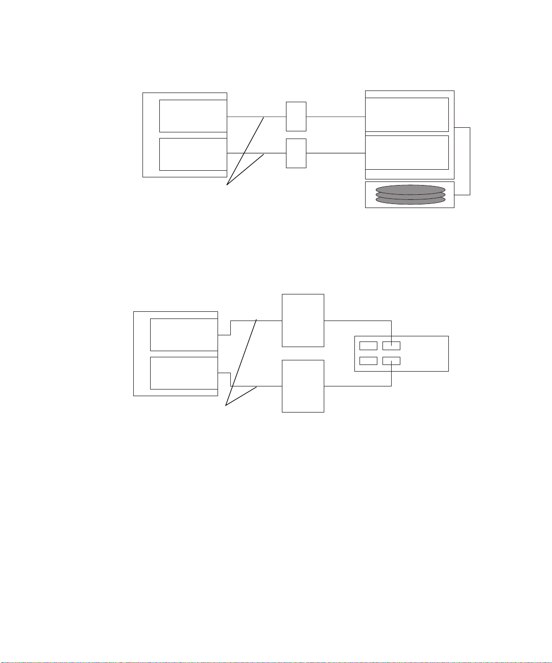
FIGURE 2-1 shows one host connected through fiber-optic cables to one Sun StorEdge
A3500FC controller module. Each controller module has two Fibre Channel ports.
FIGURE 2-2 shows one host connected through fiber-optic cables to one Sun StorEdge
A5200 controller module. Each controller module has two Fibre Channel ports.
FIGURE 2-3 shows one host connected through fiber-optic cables to one Sun StorEdge
T3 partner pair.
16 Sun StorEdge Network FC Switch-8 and Switch-16 Installation and Configuration Guide • October 2001
Page 47
Sun StorEdge A3500FC Arrays
Host
Switches
Controller A
Host adapter
SL
FC-AL ports
Controller B
Host adapter
SL
FC-AL ports
SCSI x 5
Fiber-optic cables
Drive tray x 5
FIGURE 2-1 Single Host Connected to One Sun StorEdge A3500FC Controller Module
Switches
Host
Sun StorEdge A5200 array
SL SL
IBA
IBB
SL SL
Fiber-optic cables
FIGURE 2-2 Single Host Connected to One Sun StorEdge A5200 Array
Chapter 2 Configurations 17
Page 48

Host
Host Adapter
Switches
F
TL
Sun StorEdge T3 partner pair
Host Adapter
Fiber-optic cables
FIGURE 2-3 Single Host Connected to One Sun StorEdge T3 Partner Pair
TL
F
Single Host Connected to Multiple Storage Arrays
FIGURE 2-4 shows one host connected through fiber-optic cables to Sun StorEdge
A3500FC controller modules. You can connect controller modules in the same or
separate cabinets.
FIGURE 2-5 shows one host connected to multiple Sun StorEdge A5200 arrays.
FIGURE 2-6 shows one host connected to Multiple Sun StorEdge A5200 arrays and a
Single FC-Tape library.
FIGURE 2-7 shows a single host connected to multiple Sun StorEdge T3 partner pairs.
FIGURE 2-8 shows a single host connected to multiple Sun StorEdge T3 arrays and
multiple Sun StorEdge A3500FC arrays.
FIGURE 2-9 shows a single host with cascading switches connected to a Sun StorEdge
T3 array and a local storage Sun StorEdge A5200 array and Sun StorEdge T3 array.
Note – You can attach different types of storage devices to the same switch, as long
as the storage devices are on different zones.
Each controller that is connected to a switch must have a unique loop ID. Whenever
you add a second controller to a switch, make sure that the loop ID of the controller
being connected is different from the loop ID of any other controller currently
connected to the same switch. See “Setting the Loop ID” on page 32-34 for
instructions about setting the loop ID.
18 Sun StorEdge Network FC Switch-8 and Switch-16 Installation and Configuration Guide • October 2001
Page 49

Caution – Make sure that the controller module of the array is split between two
switches. For example, connect controller A to switch 1 and controller B to switch 2.
Chapter 2 Configurations 19
Page 50

Host
Host Adapter
Host Adapter
Sun StorEdge A3500FC Array
Controller A
FC-AL port
Controller B
FC-AL port
SCSI x 5
Drive tray x 5
Sun StorEdge A3500FC Array
Switches
SCSI x 5
Drive tray x 5
Sun StorEdge A3500FC Array
Drive tray x 5
FIGURE 2-4 Single Host Connected to Multiple Sun StorEdge A3500FC Arrays,
All SL Ports
20 Sun StorEdge Network FC Switch-8 and Switch-16 Installation and Configuration Guide • October 2001
SCSI x 5
Page 51

Sun StorEdge A5200 arrays
SL
IBA
IBBSwitches
Host
SL SL
SL
Host Adapter
IBA
IBB
Host Adapter
SL
SL
SL
SL
FIGURE 2-5 Single Host Connected to Multiple Sun StorEdge A5200 Arrays,
All SL Ports
IBA
IBB
Chapter 2 Configurations 21
Page 52

Host
Switch 0
1
3
5
Sun StorEdge A5200 arrays
IBA
IBB
2
4
6
Host Adapter
8
7
IBA
IBB
2
Host Adapter
1
4
3
6
5
7
8
IBA
Switch 1
IBB
Switch 0
SL Zone 1 = Ports 1,2,3,4,6
Ports = All SL
SL Zone 2 = Ports 5,7,8
FC Tape library
Ports = All SL
Switch 1
SL Zone 1’ = Ports 1,2,3,4,6
Ports = All SL
SL Zone 2’ = Ports 5,7,8
Ports = All SL
FIGURE 2-6 Single Host Connected to Multiple Sun StorEdge A5200 Arrays and a Single
FC-Tape Library
22 Sun StorEdge Network FC Switch-8 and Switch-16 Installation and Configuration Guide • October 2001
Page 53

Sun StorEdge T3 partner pairs
Host
Switches
TL
TL
F
Host Adapter
Host Adapter
TL
TL
TL
TL
F
TL
TL
FIGURE 2-7 Single Host Connected to Multiple Sun StorEdge T3 Partner Pairs
Chapter 2 Configurations 23
Page 54
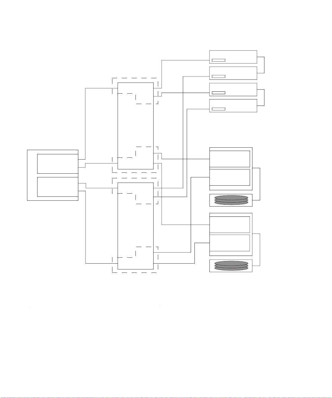
Switch 0
Sun StorEdge T3 partner pairs
Host
Host Adapter
Host Adapter
1
3
5
7
9
11
13
15
1
3
5
7
9
11
13
15
10
12
14
16
10
12
14
16
2
4
6
8
Sun StorEdge A3500 FC array
Controller A
FC-AL Port
Controller A
FC-AL Port
2
SCSI
x 5
4
6
8
Controller A
FC-AL Port
Controller A
FC-AL Port
SCSI
x 5
Switch 1
Hard zone 1 = Ports 1-8
Hard zone 2= Ports 9-16
Switch 0
Nameserver Zone 1 = Ports 1,2,4
Ports: 1 = F
Ports: 2 = TL
Ports: 4 = TL
Segmented loop zone 1 = Ports 14,15,16
Ports = All SL
FIGURE 2-8 Single Host Connected to Multiple Sun StorEdge T3 Arrays and Multiple Sun
Switch 1
Nameserver zone 1’ = Ports 1,2,4
Ports: 1 = F
Ports: 2 = TL
Ports: 4 = TL
Segmented loop zone 1’ = Ports 14,15,16
Ports = All SL
StorEdge A3500FC Arrays
24 Sun StorEdge Network FC Switch-8 and Switch-16 Installation and Configuration Guide • October 2001
Page 55

Zone 1
Zone 1
2
1
3
4
5
6
Host
8
7
Host Adapter
Switch 0
Host Adapter
Host Adapter
Zone 1’
Host Adapter
1
2
4
Switches 0,2 and
Switches 1,3
Nameserver Zone 1,1’
Switch 0,1
Ports: 1 = F
Ports: 2 = T
Switch 2,3
Ports: 1= T
Ports: 2 = TL
3
5
7
Switch 1
6
8
Ports: 4 = TL
Switch 0 and Switch 1
Segmented Loop Zone 1, Segmented Loop Zone 1’
Ports = 3,4,6
All Ports are SL
Switch 0 and Switch 1
Nameserver Loop Zone 1 and 1’ respectively
Ports: 5 = F
Ports: 7 = TL (empty)
Ports: 8 = TL
1
3
5
7
9
11
13
15
Switch 2
Zone 1
1
3
5
7
9
11
13
15
Switch 3
2
4
6
8
10
12
14
16
IBA
IBB
IBA
IBB
2
4
6
8
10
12
14
16
FIGURE 2-9 Single Host Cascading Switches Connected to Sun StorEdge T3 Array and
Local Storage Sun StorEdge A5200 Array and Sun StorEdge T3 Array
Chapter 2 Configurations 25
Page 56

Multihost
FIGURE 2-10 shows an example of a multihost configuration: two hosts connected
through fiber-optic cables, using switches, to two Sun StorEdge A3500FC controller
modules.
FIGURE 2-10 shows two hosts connect to a maximum of four Sun StorEdge A3500 FC
arrays.
FIGURE 2-11 shows two hosts connected to three Sun StorEdge A5200 arrays.
FIGURE 2-12 shows two hosts connected to four Sun StorEdge T3 partner pairs.
FIGURE 2-13 shows two hosts connected to a Sun StorEdge T3 Partner Group in which
each host maintains separate, non-shared storage.
FIGURE 2-14 shows a multihost configuration with cascading switches connected to an
FC tape library, a Sun StorEdge T3 array, and a Sun StorEdge A5200 array.
26 Sun StorEdge Network FC Switch-8 and Switch-16 Installation and Configuration Guide • October 2001
Page 57
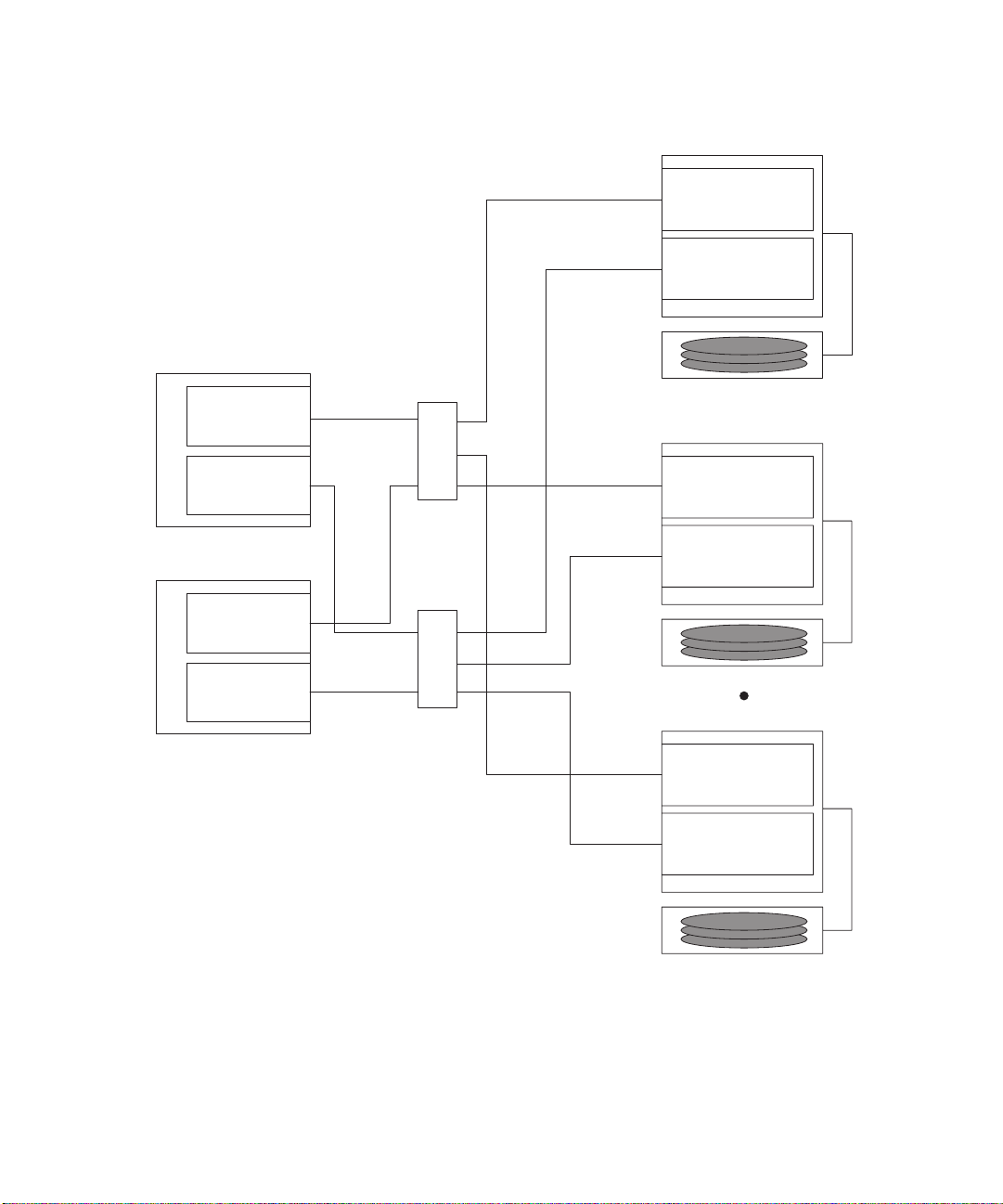
Host
Host Adapter
Host Adapter
Switches
A
Sun StorEdge A3500 FC Arrays
Controller A
FC-AL Port
Controller B
FC-AL Port
Drive Tray x 5
Controller A
FC-AL Port
Controller B
SCSI x 5
Host Adapter
Host Adapter
FIGURE 2-10 Two Hosts Connected to a Maximum of Four Sun StorEdge A3500FC Arrays
All Ports SL
FC-AL Port
SCSI x 5
B
Drive Tray x 5
Controller A
FC-AL Port
Controller B
FC-AL Port
SCSI x 5
Drive Tray x 5
Chapter 2 Configurations 27
Page 58
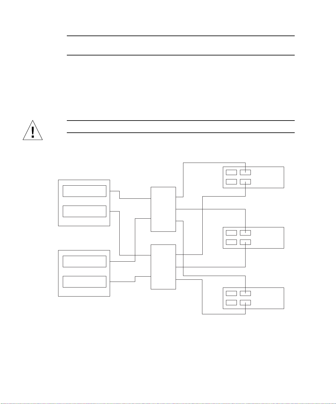
Note – You can attach different storage types to the same switch so long as the
storage devices are on different zones.
Each controller that is connected to a switch must have a unique loop ID. Whenever
you add a second controller to a switch, make sure that the loop ID of the controller
being connected is different from the loop ID of any other controller currently
connected to the same switch.
Refer to “Setting the Loop ID” on page 32 for instructions on setting the loop ID of a
controller.
Caution – Ensure that the controller modules are not connected to the same switch.
Sun StorEdge A5200 arrays
Host
Switches
Host Adapter
Host Adapter
Host Adapter
Host Adapter
FIGURE 2-11 Two Hosts Connected to Three Sun StorEdge A5200 Arrays, All Ports SL
IBA
IBB
IBA
IBB
IBA
IBB
28 Sun StorEdge Network FC Switch-8 and Switch-16 Installation and Configuration Guide • October 2001
Page 59

Sun StorEdge T3 partner pairs
Host
Host Adapter
Host Adapter
Host
Host Adapter
Host Adapter
Switches
TL
F
TL
TL
F
TL
TL
F
TL
TL
F
TL
FIGURE 2-12 Two Hosts Connected to Four Sun StorEdge T3 Partner Pairs
Chapter 2 Configurations 29
Page 60
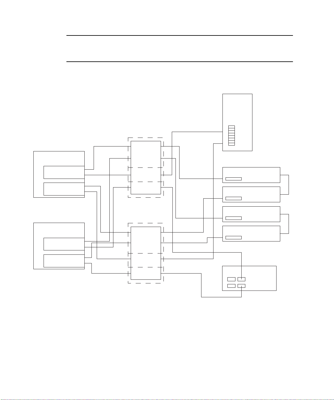
Note – You must enable Sun StorEdge Traffic Manager software or use Veritas
VxDMP 3.2 for failover across multiple hosts to work. Set the mp_support on the
Sun StorEdge T3 to mpxio.
Sun StorEdge L180 or L700 FC Tape Library
Switch 0
Sun Enterprise 420
Host Adapter
Host Adapter
Sun Enterprise 3500
Host Adapter
Host Adapter
Switch 0,1
Nameserver zones
Ports 1 = F
Ports 3 = F
Ports 2 = TL
Ports 4 = TL
SL Zones
Ports 5, 6 are SL ports
SL zone
Ports 7, 8 are SL ports
1
3
5
7
Switch 1
1
3
5
7
2
4
Sun StorEdge T3 partner pairs
6
8
2
4
6
8
Sun StorEdge A5200 Array
IBA
IBB
FIGURE 2-13 Two Hosts Connected to Sun StorEdge T3 Partner Group: Each Host with
Separate Non-shared Storage
30 Sun StorEdge Network FC Switch-8 and Switch-16 Installation and Configuration Guide • October 2001
Page 61
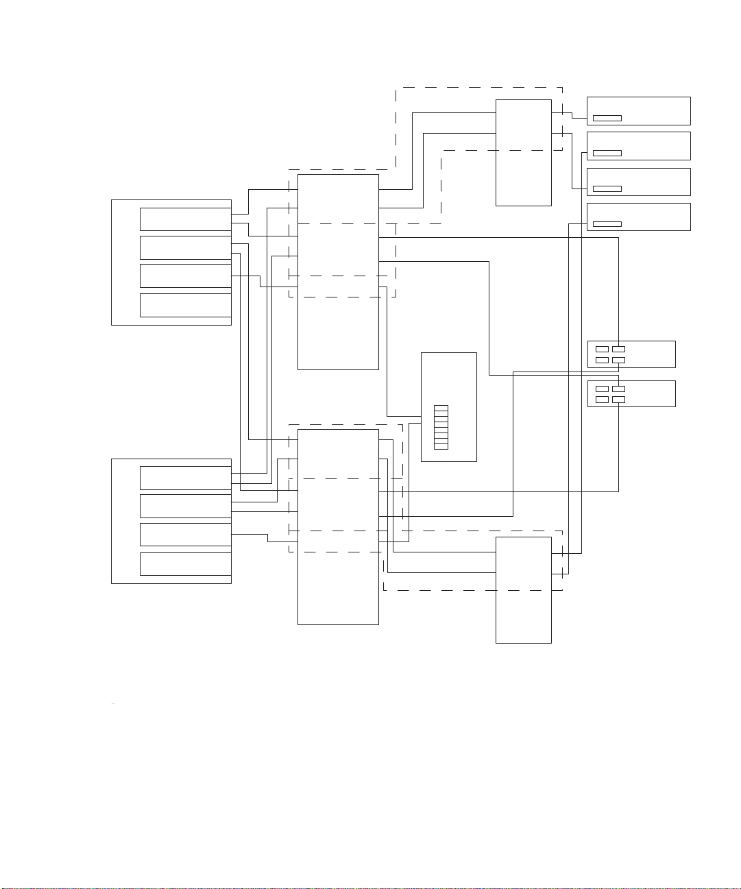
Sun Enterprise E220
Host A
Host Adapter
Host Adapter
Host Adapter
Host Adapter
1
3
5
7
9
11
13
15
Switch 0
10
12
16
2
4
6
8
14
Tape library
1
2
4
3
6
5
7
8
Sun StorEdge A5200 Array
Sun Enterprise E3000
Host A
Host Adapter
Host Adapter
Host Adapter
Host Adapter
Nameserver zone and SL zone
cannot be in the same zone.
Switches 0,1,2,3
Nameserver Zone 1 and 1’
Switch 0,1
Ports 1 = F
Ports 2 = T
Ports 3 = F
Port 4 = T
Switch 2,3
Ports 1 = T
Ports 2 = TL
Ports 3 = T
Ports 4 = TL
FIGURE 2-14 MultiHost with Cascading Switches Connected to FC-Tape, Sun StorEdge T3
Array, and Sun StorEdge A5200 Array
1
3
5
7
9
11
13
15
2
4
6
8
10
12
14
16
Switch 1
Segmented Loop Zones 1,1’
Switch 1,1
Ports 5,6,7,8 All Ports SL
Ports 9,10 All ports SL
2
1
3
4
6
5
8
7
Switch 3
Tape libraries
The tape library controller
is accessible to one host only.
Chapter 2 Configurations 31
Page 62
Note – You must enable Sun StorEdge Traffic Manager software or use Veritas
VxDMP 3.2 for failover across multiple hosts to function. The mp_support on the
Sun StorEdge T3 should be set to mpxio.
Setting the Loop ID
Setting the loop ID of the Sun StorEdge A3500 FC array is different from the
procedure for the Sun StorEdge A5200 array and for the Sun StorEdge T3 array.
▼ To Set the Loop ID of a Sun StorEdge A3500 FC
Controller
This section explains how to set the loop ID of a Sun StorEdge A3500 FC controller
that is connected to a switch.
Tools and equipment needed:
■ Needle-nose pliers
■ Jumpers (supplied with the Sun StorEdge A3500/A3500FC unit)
■ Antistatic wrist strap
Every device attached to a SCSI or FC-AL bus must have a unique controller module
ID number in order to communicate. The factory default ID settings for controller A
and B are ID 5 and ID 4, respectively.
Caution – Do not configure more than four controller modules on the same loop.
1. Attach the antistatic wrist strap to your wrist and to the metal casing of the switch.
2. Locate the 16 pins on the rear of the FC-AL controller module (
The eight pins on the right determine the host ID for controller 1 (A); the pins on the
left determine the ID for controller 2 (B).
3. Install the jumpers on the pins as shown in
If necessary, use the needlenose pliers to remove the jumpers.
32 Sun StorEdge Network FC Switch-8 and Switch-16 Installation and Configuration Guide • October 2001
FIGURE 2-15.
FIGURE 2-15).
Page 63

▼ To Verify the Loop ID of the Sun StorEdge
A5200 and T3 Arrays
● Make sure that each array on a single loop has a unique target ID.
If two Sun StorEdge T3 arrays have the same target ID on the same FC-AL loop, the
software does not recognize their presence.
Refer to the Sun StorEdge T3 documentation for information on verifying the loop
ID. Refer to the Sun StorEdge A5200 documentation on verifying the loop ID for the
Sun StorEdge A5200 array.
Chapter 2 Configurations 33
Page 64

Controller B Controller A
Controller B Controller A
ID AL
8
4
2 1 Dec PA
15
16
8421 8421
1
2
842 1 Dec PA
0EF
1E8
2E4
3E2
4E1
5E0
6DC
7DA
8D9
9D6
10 D5
ID AL
0EF
1E8
2E4
3E2
4E1
5E0
6DC
7DA
8D9
9D6
10 D5
11 D4
12 D3
13 D2
14 D1
11 D4
12 D3
13 D2
14 D1
15 CE 15 CE
FIGURE 2-15 Sun StorEdge A3500 FC-AL ID Settings
34 Sun StorEdge Network FC Switch-8 and Switch-16 Installation and Configuration Guide • October 2001
Page 65

CHAPTER
3
Installation Overview
This chapter contains an overview of the tasks required for installing new Sun
StorEdge Network FC Switch-8 and Switch-16 hardware and software. It also
provides an overview of the tasks required to update the software for previously
installed Sun StorEdge Network FC Switch-8 and Switch-16 SAN switches.
To install the software for a Sun StorEdge Network FC Switch-8 and Switch-16
Version 3.0 switch, refer to the instructions in Chapter 6 in this guide.
To upgrade software on a Sun StorEdge Network FC Switch-8 and Switch-16,
Version 2.0/2.1, switch, refer to the instructions in Chapter 7 in this guide. After you
have performed the upgrade to the Version 3.0 level, you can use the new features
and functions in Version. 3.0.
“Software Components and Patches” on page 36
“Overview-Installing a New Switch” on page 37
“Overview for Software Installations” on page 38
“To Download Patches Using PatchPro Interactive” on page 39
“To Download Patches Using PatchPro Expert” on page 40
Refer to the Sun StorEdge Network FC Switch-8 and Switch-16 Release Notes,
shipped with your system, for the most recent versions and patches.
35
Page 66

Software Components and Patches
For the most recent updates to TABLE 3-1, refer to the Sun StorEdge Network FC Switch-
8 and Switch-16 Release Notes .
TABLE3-1 Minimum Software Component Versions and Patches
Non-Bundled Software Minimum Version Minimum Patch
Recommended and Security Patches - Solaris 8 04/01 108982-09
108984-08
109529-06
SAN Foundation Kit package SUNWsan
SAN Foundation Kit patch 111847-01
Sun StorEdge Traffic Manager patch 111412-04
fctl/fp/fcp/usoc driver patch 111095-05
fcip driver patch 111096-03
/kernel/drv/qlc driver patch 111097-04
luxadm, liba5k and libg_fc patch 111413-04
/kernel/fs/specfs 111267-02
cfgadm fp plug-in 32-bit
cfgadm fp plug-in 64-bit
cfgadm fp plug-in for Library patch
/kernel/drv/ses 110614-02
Raid Manager RM6 6.22.1
Solstice Disk Suite™ 4.2.1 4.2.1 108693-06
Component Manager 2.2
Sun StorEdge A5200 IB Firmware 1.09
Switch Firmware 3.04.62 110696-03
SANsurfer Switch Manager™ (SUNWsmgr) 2.07.54
Sun StorEdge PCI Single Fibre Channel Network
Adapter Fcode x6799a
Sun StorEdge PCI Dual Fibre Channel Network
Adapter+ Fcode x6727a
StorageTek™ 9840 Native FC 1.28.126
Sun StorEdge T3 Firmware 1.17b 109115-09
1
1.12
1.12
SUNWcfpl
SUNWcfplx
111846-01
110696-03
36 Sun StorEdge Network FC Switch-8 and Switch-16 Installation and Configuration Guide • October 2001
Page 67

TABLE3-1 Minimum Software Component Versions and Patches (Continued)
Non-Bundled Software Minimum Version Minimum Patch
Sun StorEdge T3 18Gb disk Firmware 109115-09
VERITAS Volume Manager™ 3.2
VERITAS File System 3.4
Instant Image™ 3.0
fast Write Cache™ 3.0
SNDR 3.0
AP 2.3.1 110722-01
110432-01
StorTools™ 4.1
Sun StorEdge Network Storage Agent™ 2.1
VERITAS NetBackup™ 3.4 110539-04
Solstice Backup™ 6.0
Sun Enterprise 3x00/4x00/5x00/6x00 Flash
prom
Sun Fire™ 3800/4800/4810/6800 Flash prom 5.11.6 111346-02
E450 Flash prom 3.22.0 106122-09
E250 Flash prom 3.22.0 106503-06
E420R Flash prom 3.29.0 109082-04
1. After patch 110696-03 is applied, the SANsurfer GUI windows display the package level as 2.08.30.
3.2.28 103346-29
Overview-Installing a New Switch
The following provides the major steps for installing either the 8-port or 16-port
switch hardware and software.
1. Select the area for the expansion cabinet onto which you plan to install the switch.
Be sure to allow for the minimum airflow, temperature, and power restrictions. See
the SANbox-16STD Fibre Channel Switch Installer's/User's Manual for instructions.
2. Verify the configuration for your system.
Supported configurations are detailed in Chapter 2, "Configuration."
Chapter 3 Installation Overview 37
Page 68

3. Install the GBICs.
See the Sun Switch Management Installer's/User's Manual for the 8-port switch, or
the SANbox Segmented Loop Switch User's Manual for instructions.
4. Install the vent panel.
See "Installing the Vent Panel" on page 47.
5. Connect the cables and power cords.
See Chapter 2 for configuration information.
See also "Connecting the Cables" on page 50.
6. Configure the switch for the network.
See Chapter 5 for information on configuring the switch to the network.
7. Install the SANSurfer 3.0 application.
See "Installing the Sun StorEdge Network FC Switch 3.0 GUI" on page 61 for
information on installing the GUI application.
8. Confirm the switch firmware and GUI revision level for your switch.
Refer to TABLE 3-1.
Overview for Software Installations
To install software in your Sun StorEdge Network FC Switch-8 and Switch-16 for
the first time, see “PatchPro™ Interactive” on page 38 and “To Download Patches
Using PatchPro Interactive” on page 39.
To upgrade your software to the Version 3.0 software, see “PatchPro Expert” on
page 39 and “To Download Patches Using PatchPro Expert” on page 40.
PatchPro™ Interactive
Use PatchPro Interactive the first time you install Version 3.0 software. After the
Sun StorEdge Network FC Switch-8 and Switch-16, Version 3.0, software has been
installed, use PatchPro Expert to perform future upgrades to the latest software
revision levels.
38 Sun StorEdge Network FC Switch-8 and Switch-16 Installation and Configuration Guide • October 2001
Page 69

PatchPro Expert
PatchPro Expert analyzes the system configuration and currently installed patches
with the latest patch revisions available on the http://sunsolve.Sun.Com. If new
patch revisions are available on http://sunsolve.Sun.Com, it generates a list and
allows you to download the patches. It also generates a list to indicate the order in
which patches should be installed.
▼ To Download Patches Using PatchPro
Interactive
PatchPro Interactive does not verify that the selected configuration is a valid
configuration, nor does it interrogate your system to discover which patches may
already be installed. PatchPro presents to the user all the patches (in install order)
for the selected configuration. A README.txt file with the install order is supplied
as part of the tar file.The patch installation order listed in the README.txt file may
not coincide with those listed in this book. Follow the installation order defined in
TABLE 6-2.
1. For Sun StorEdge Network FC Switch-8 and Switch-16, Switch 3.0, go to
http://sunsolve.sun.com.
2. Select Patches from the menu on the left side of the page.
3. From the same menu, select PatchPro.
4. From the same menu, select Storage Products.
5. Select the PatchPro Interactive link on the main page.
6. Select the pieces of hardware/software for analysis:
a. From the SAN Product Bundle section, select Network FC Switch and version
3.0.
This will provide the driver and utility patches, Sun StorEdge Traffic Manager, the
switch firmware and the switch GUI patch necessary to use and install the 3.0
software.
b. From the software section, select the packages that you have installed or are
planning to install before loading the patches.
This selection provides you with patches to the packages, but it does not provide
the package itself. You must obtain each package separately, and install each one
on your host before you install the patches.
c. Select the disk arrays that you plan to connect to your SAN switch.
Chapter 3 Installation Overview 39
Page 70

d. Under switches and HBAs, select the HBAs in your SAN.
You do not need to select the switches under this block because the switch GUI/
firmware was captured when you selected the Network FC Switch, Version 3.0.
7. When your selections are complete, select Generate Patch List.
An ordered list of the patches required for your selections displays. You can choose
which patches to download, or you can download them all in one tar file.
If the patch list contains any contract patches, provide your SunSolve User ID &
password.
▼ To Download Patches Using PatchPro Expert
PatchPro Expert analyzes the system configuration and currently installed patches
with the latest patch revisions available on http://sunsolve.Sun.Com. If newer patch
revisions are available on http://sunsolve.Sun.Com, it generates a list and allows
you to download the patches. It also generates a list to indicate the order in which
patches should be installed. Follow the installation order outlined in
1. Go to http://sunsolve.sun.com.
2. Select Patches from the menu on the left side of the page.
3. From the same menu select PatchPro.
TABLE 6-2.
4. From the same menu select Storage Products.
5. Select the PatchPro Expert link on the main page.
This analyzes the currently installed patches on the system and generates the list of
patches that need to be updated.
After you follow the instructions on the screen and select the hardware products
attached to your system, an ordered list of the patches required for your system
displays.
6. Download the patches.
40 Sun StorEdge Network FC Switch-8 and Switch-16 Installation and Configuration Guide • October 2001
Page 71

CHAPTER
4
Hardware Installation
This chapter describes how to mount the switch in an expansion cabinet, install the
vent panel, and connect the switch to your disk arrays. This chapter is arranged as
follows:
“Preparing for the Installation” on page 41
“Attaching the Mounting Rails to the Expansion Cabinet” on page 42
“Installing the Switch” on page 46
“Installing the Vent Panel” on page 47
“Connecting the Cables” on page 50
Preparing for the Installation
Before you begin installing the switch:
■ Refer to the Rackmount Placement Matrix, available on the Sun Microsystems web
site for hole positions in an expansion cabinet.
http://www.sun.com/products-n-solutions/hardware/docs/
Network_Storage_Solutions/Cabinets_and_Enclosures/index.html
■ If you currently have a hub installed in your expansion cabinet, you must remove
it, and the mounting tray, prior to installing the switch and mounting rails. Refer
to the hub removal instructions in the Sun StorEdge FC-100 Hub Installation and
Service Manual, which is packaged with the hub.
41
Page 72

Attaching the Mounting Rails to the Expansion Cabinet
The 8-port switch comes with a set of mounting rails that holds two switches. The
16-port switch comes with individual rails for each switch.
This section describes how to attach the mounting rails to an expansion cabinet for
two-switch and four-switch configurations.
“To Attach Mounting Rails for Two 8-port Switches” on page 42
“To Attach Mounting Rails for Four 8- Port Switches” on page 44
Installing the Mounting Rails for 8-Port Switches
▼ To Attach Mounting Rails for Two 8-port
Switches
1. Before you install the rails into the cabinet, loosely start two stopper screws into
each mounting rail. (
FIGURE 4-1).
2. Working from the back of the cabinet, loosely start two screws into the cabinet
rails. (
FIGURE 4-1.)
Refer to the Rackmount Placement Matrix for the locations of the screw holes of your
configuration.
42 Sun StorEdge Network FC Switch-8 and Switch-16 Installation and Configuration Guide • October 2001
Page 73
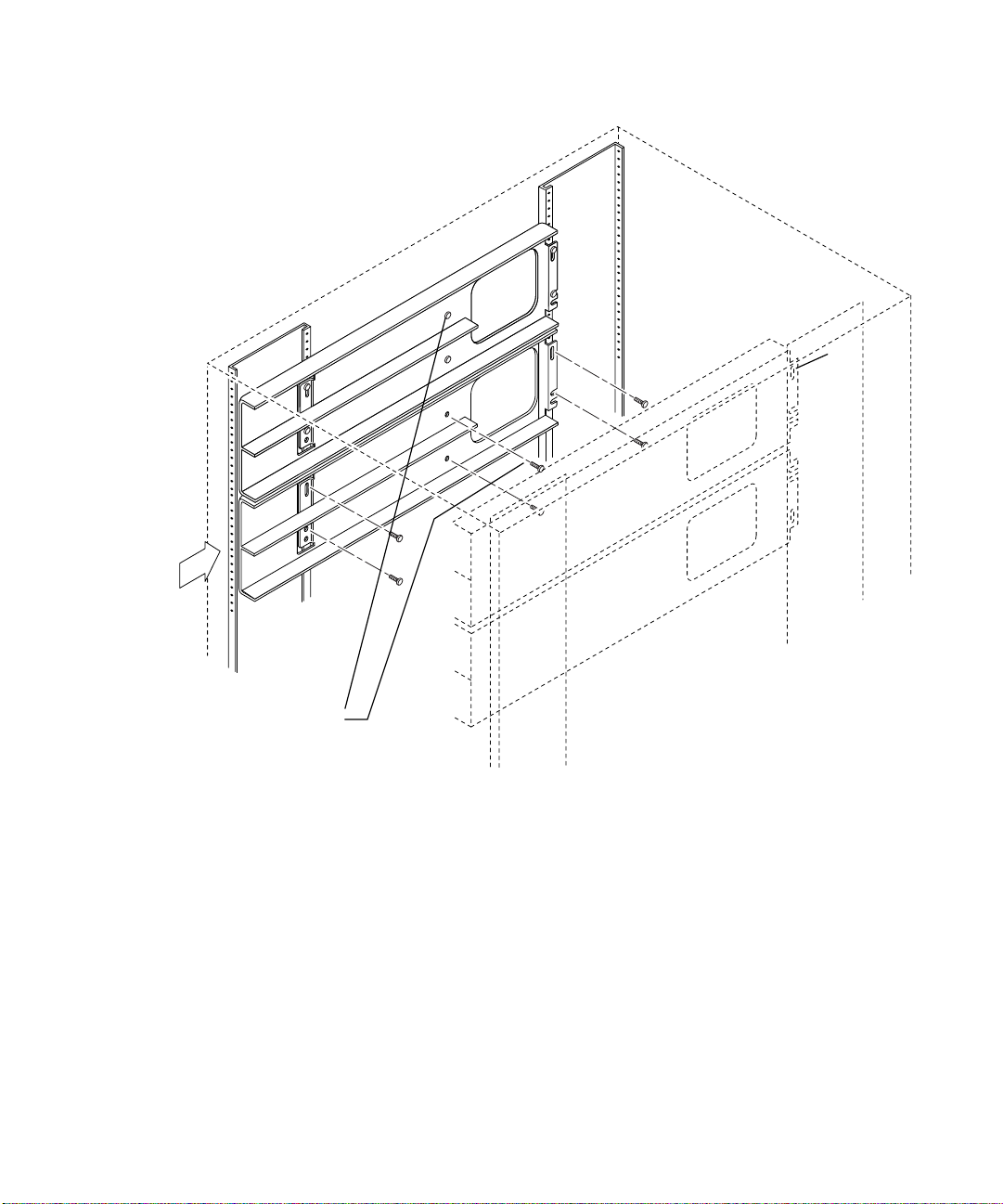
Stopper screws
Back
L
R
FIGURE 4-1 Attaching the Mounting Rails
3. Working from the front of the cabinet, install the mounting rails by sliding the
keyhole slot in the rail onto the screw.
The rails for left and right are identical, but reversed, for the two sides.
The large hole is oriented near the back for both rails.
Use the slot marked L for the left rail. Use the slot marked R for the right rail.
(
FIGURE 4-2)
Chapter 4 Hardware Installation 43
Page 74
RL
FIGURE 4-2 Detail of Rail Slots
4. Install three 10-32 screws on each rail.
5. Tighten the fourth screw.
▼ To Attach Mounting Rails for Four 8- Port
Switches
1. Mount the first two switches.
See “To Attach Mounting Rails for Two 8-port Switches” on page 42.
2. Before you install the rails into the cabinet, loosely start two stopper screws into
each rail (see
3. Working from the back of the cabinet, loosely start two screws for the mounting
rails into the cabinet (see
Refer to the Rackmount Placement Matrix for the locations of the screw holes for your
configuration.
FIGURE 4-2).
FIGURE 4-2).
4. Working from the front of the cabinet, install the mounting rails by sliding the
slot in each rail onto the screw.
The large hole is oriented near the rear for both rails. Use the slot marked L for the
left rail. Use the slot marked R for the right rail. (
44 Sun StorEdge Network FC Switch-8 and Switch-16 Installation and Configuration Guide • October 2001
FIGURE 4-2)
Page 75

▼ To Attach Mounting Rails for Two 16-Port
Switches
Each 16-port switch comes with two identical mounting rails. There is no difference
between the left rail and the right rail.
1. Before you install the rails into the cabinet, loosely start two stopper screws into
each rail (see
2. Working from the rear of the cabinet, loosely start two screws into the cabinet for
each mounting rail, one at each end (see
Refer to the online Rackmount Placement Matrix for the correct hole positions for your
configuration.
Note – Install the screws into the cabinet holes before you place the rails.
Stopper screw hole
FIGURE 4-3).
FIGURE 4-3).
Preinstalled screws
Preinstalled screws
FIGURE 4-3 Attaching the Mounting Rails for a 16-port Switch
3. Working from the front of the cabinet, install the mounting rails by sliding the
keyhole slot in the rail onto the screw.
In a two-switch configuration install the lower rail before you install the upper one.
Chapter 4 Hardware Installation 45
Page 76

4. Insert the remaining screws through the mounting rail into the cabinet rail.
Do not tighten any of the screws until you have them all loosely started.
5. Tighten all the screws when all four screws in each bracket are in place.
The order of tightening does not matter.
Installing the Switch
▼ To Install the 8-port or 16-port Switch into the
Cabinet
1. From the front of the cabinet, slide the first switch into the lowest of the mounting
rails.
The GigaBit Interface Converter (GBIC) side goes toward the back of the rack. The
switch casing stops moving when it meets the stopper screw on the mounting rail.
2. Insert the front lockdown screws (see
3. Tighten the stopper screws.
FIGURE 4-4 for 8-port switch only).
46 Sun StorEdge Network FC Switch-8 and Switch-16 Installation and Configuration Guide • October 2001
Page 77
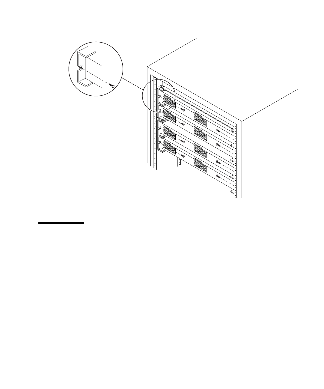
FIGURE 4-4 Installing Four 8-Port Switches Into the Mounting Rails
Installing the Vent Panel
This section describes how to install the vent panel on the switches in your
configuration.
“To Install the Vent Panel on Two 8-Port Switches” on page 47
“To Install the Vent Panels on Four 8-Port Switches” on page 48
“To Install the Vent Panel on a 16-Port Switch” on page 49
▼ To Install the Vent Panel on Two 8-Port Switches
1. Mount the 1-U filler panel at the very top. Tighten the captive screws.
Chapter 4 Hardware Installation 47
Page 78
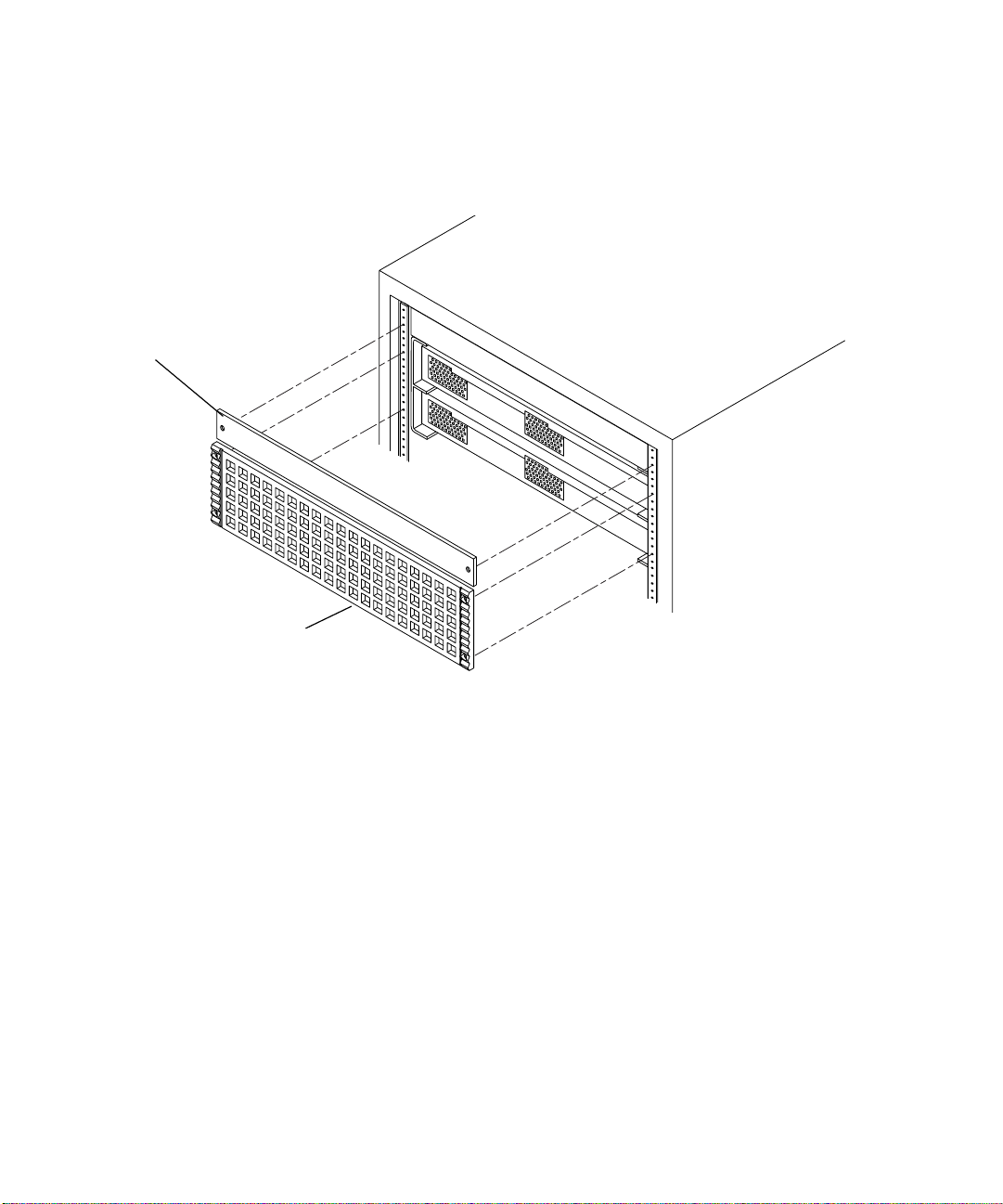
2. Mount the 1-U filler panel above the vent panel and below the existing 2-U filler
panel.
3. Tighten the captive screws.
1-U filler panel
3- U Vent panel
FIGURE 4-5 Installing the Vent Panel— Two 8-Port Switch Configuration
▼ To Install the Vent Panels on Four 8-Port
Switches
1. Mount each of the two vent panels over the front of a set of two switches.
No filler panel is necessary.
2. Tighten the captive screws.
48 Sun StorEdge Network FC Switch-8 and Switch-16 Installation and Configuration Guide • October 2001
Page 79
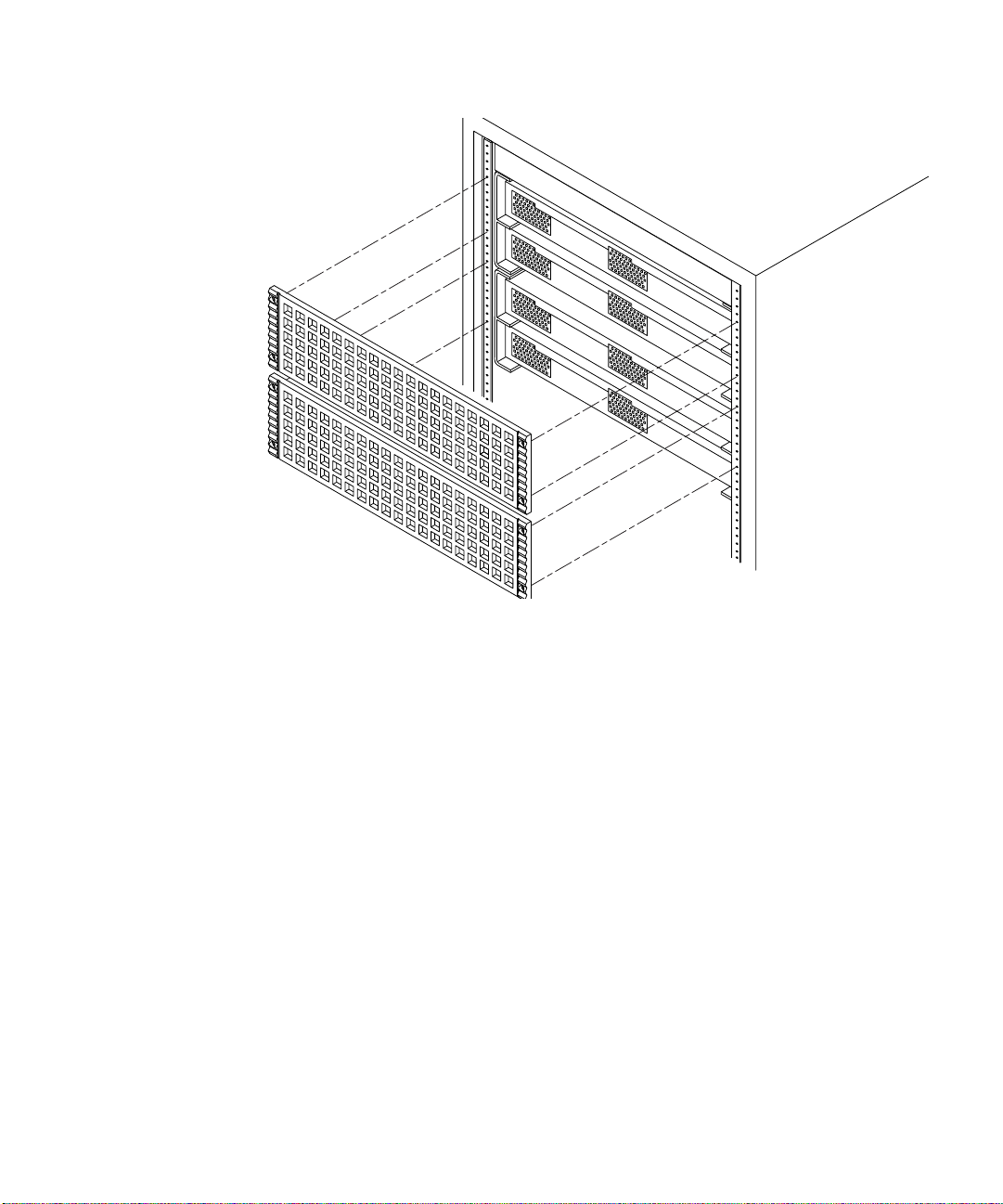
FIGURE 4-6 Installing the Vent Panel—Four 8-Port Switch Configuration
▼ To Install the Vent Panel on a 16-Port Switch
Each 16-port switch comes with its own vent panel.
1. Mount a vent panel over the front of each switch.
No filler panel is necessary.
2. Tighten the captive screws.
Chapter 4 Hardware Installation 49
Page 80

FIGURE 4-7 Installing the Vent Panel for a 16-Port Switch
Connecting the Cables
Some storage cabinets may have shorter and fewer power cords. In these cases, you
must use the Y cable, provided with your switch, to increase the number of power
connections and provide adequate power cord length. Install the Y cables only in the
J8 or J12 connections of the power sequencer.
“To Connect the Cables to a Sun StorEdge T3 Array” on page 51
“To Connect the Cables to a Sun StorEdge A5200 Array” on page 52
“To Connect the Cables to a Sun StorEdge A3500FC Array” on page 52
“To Connect the Cables to a Sun StorEdge L180 or L700 FC Tape Library” on page 56
50 Sun StorEdge Network FC Switch-8 and Switch-16 Installation and Configuration Guide • October 2001
Page 81

Sun StorEdge A5200 and T3 Arrays
▼ To Connect the Cables to a Sun StorEdge
T3 Array
1. Power off the system.
For instructions about powering off the Sun StorEdge T3 Array, refer to the
documentation that came with the array.
2. Unplug the power cord from both fan trays and from the J12 connections on both
sequencers.
See
FIGURE 4-8 for the J12 location.
J12
FIGURE 4-8 Power Sequencer
3. From the back of the cabinet, follow the route of the existing cables to the sides
and up the rear of the cabinet, to the level of the switches.
The Y cable on the back sequencer routes up the right side. The Y cable on the front
sequencer routes up the left side. Use tie wraps as necessary to secure the cables.
4. Connect the Y cable on the right side to the right side of the fan tray and the right
side of number 8, T3.
5. Connect the Y cable on the left side to the left side of the fan tray and the left side
of number 8, T3.
6. Connect the existing R8 cable to the lowest switch.
7. Connect the existing L8 cable to the highest switch.
J8
Chapter 4 Hardware Installation 51
Page 82

▼ To Connect the Cables to a Sun StorEdge A5200
Array
If the existing power cords are too short, replace them with the Y cable.
1. Power off the system.
For instructions about powering off the Sun StorEdge A5200 Array, refer to the
documentation that came with the array.
2. Remove the lower vented side panel from the right side.
3. Working from the back, push the lowest Sun StorEdge A5200 array about eight
inches toward the front of the cabinet.
This provides access to the cables.
4. Disconnect the power cord from the J8 port on both sequencers.
See
FIGURE 4-8 for J8 location.
5. Connect the Y cable to the J8 port on both sequencers.
6. Replace the side vent panel.
7. From the front, push the lowest Sun StorEdge A5200 array back into place.
8. Connect one end of the left Y cable to the lowest switch. Connect the other end to
the next switch.
If there are four switches, connect one end of the right Y cable to the third switch.
Connect the other end of the Y cable to the highest switch.
9. From the back of the cabinet, follow the route of the existing cables to the sides
and up the rear of the cabinet, to the level of the switches.
The Y cable on the back sequencer routes up the right side. The Y cable on the front
sequencer routes up the left side. Use tie wraps as necessary to secure the cables.
▼ To Connect the Cables to a Sun StorEdge
A3500FC Array
When you have the switch(es), vent, and filler panels in place, you must connect and
route the cables. If the existing power cords are too short, replace them with the Y
cable before performing this procedure.
52 Sun StorEdge Network FC Switch-8 and Switch-16 Installation and Configuration Guide • October 2001
Page 83

1. Working from the back, connect the power cord(s).
FIGURE 4-9 shows the 8-port switch power connector.
FIGURE 4-10 shows the 16-port switch power connector.
FIGURE 4-11 shows the power connections for two or four switches.
Allow the power cord to dangle temporarily.
GBIC
Power
Port 1
Port 2
Port 4
Port 3
Port 6
Port 5
Power
FIGURE 4-9 The 8-Port Switch Power Connector
Port 2
GBIC
Port 1 Port 3 Port 5 Port 7 Port 9 Port 11 Port 13 Port 15
FIGURE 4-10 The 16-Port Switch Power Connector
Port 4
Port 6 Port 8 Port 10 Port 12 Port 14 Port 16
Port 8
Port 7
microsystems
Chapter 4 Hardware Installation 53
Page 84

Switch 1
Power
cords
Switch 2
Switch 3
Switch 4
FIGURE 4-11 Power Connection for Two or Four Switches
2. Install the GBIC.
See the “Removal and Replacement Procedures” chapter of the SANbox 8/16
Segmented Loop Switch User’s Manual for instructions on installing a GBIC.
3. Use a tie wrap to secure the Fibre Channel cables, as shown in
FIGURE 4-13.
FIGURE 4-12 and
54 Sun StorEdge Network FC Switch-8 and Switch-16 Installation and Configuration Guide • October 2001
Page 85

Power
Fibre Channel cablesFibre Channel cablesFibre Channel cables
Fibre channel cables
Tie wrap
FIGURE 4-12 Cable Routing for the 8-Port Switch
Extension power cord
Fibre channel cables
microsystems
FIGURE 4-13 Cable Routing for the 16-Port Switch
Note – Connections to storage arrays are not shown in these figures.
Chapter 4 Hardware Installation 55
Page 86

▼ To Connect the Cables to a Sun StorEdge L180 or
L700 FC Tape Library
1. Refer to the installation documentation that came with your tape library for
instructions on cabling.
2. Comply with the rules for configuring an FC Tape Library with a Sun StorEdge FC
Network Switch. See “FC Tape Libraries” on page 11.
56 Sun StorEdge Network FC Switch-8 and Switch-16 Installation and Configuration Guide • October 2001
Page 87

CHAPTER
5
Switch Activation
This chapter contains the procedures for bringing the new Sun StorEdge FC Switch
3.0 software onto the network. For more details about the switch, refer to Switch
Management User ’s Manual.
“Configuring the Switch Ethernet Port” on page 57
“Installing the Sun StorEdge Network FC Switch 3.0 GUI” on page 61
“Setting the Stage Type” on page 66
Configuring the Switch Ethernet Port
The IP address of the switch is set to the default value of 10.0.0.1. You can change
this default IP address using the Reverse Address Resolution Protocol (RARP), or
the switch management GUI. This guide provides the procedures for changing the IP
address using RARP only. To set the IP address using the GUI method, see Chapter
2 in the Sun Switch Management User’s Manual .
Using RARP to Change the IP Address
You can use RARP to change the address when you first receive the switch or if you
forget the address.
The Sun StorEdge FC Switch 3.0 RARP feature automatically downloads the
assigned IP address to the switch. After you cable the switch and turn the power on,
the IP address is automatically assigned.
57
Page 88
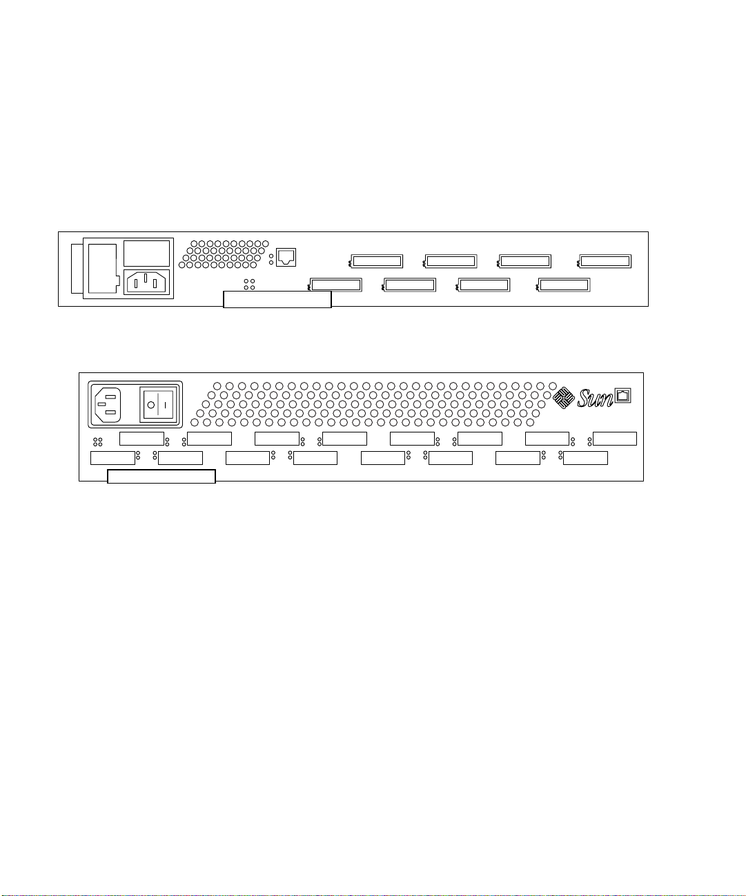
You will need the following information to change the IP address:
IP address _______________________ Contact the person who maintains your
network for this information.
MAC address _____________________ See
FIGURE 5-1 and FIGURE 5-2 for the location
of the MAC Address.
Switch name ______________________ This is the assigned name of the switch you
are installing.
MAC Address
FIGURE 5-1 Sun StorEdge Network FC Switch-8 MAC Address Location
MAC Address
microsystems
FIGURE 5-2 Sun StorEdge network FC switch-16 MAC Address Location
▼ To Set the Network IP Address Using RARP:
1. On a host connected to the same subnet as the switch, save your current
configuration.
2. Check that the /etc/ethers file exists.
# ls /etc/ethers
3. If you find the file, create the /etc/ethers.SAV backup file:
# cp -p /etc/ethers /etc/ethers.SAV
58 Sun StorEdge Network FC Switch-8 and Switch-16 Installation and Configuration Guide • October 2001
Page 89

4. Back up the affected management station configuration files:
# cp -p /etc/nsswitch.conf /etc/nsswitch.conf.SAV
# cp -p /etc/hosts /etc/hosts.SAV
5. On a host connected to the same subnet as the switch, edit the /etc/ethers file
by adding the MAC address and switch name.
For example:
8:0:20:7d:93:7e
switch-name
In this example:
■ 8:0:20:7d:93:7e is the MAC address
■ switch-name is the name of the switch you are installing.
6. Edit the /etc/hosts file with the IP address and switch name.
For example:
192.129.122.111
switch-name
In this example, 192.129.122.111 is the assigned IP address.
7. Edit the /etc/nsswitch.conf file to reference the local system files.
To ensure that the Solaris software environment uses the changes made to
/etc/ethers and /etc/hosts files, edit the host and ethers entries in the
/etc/nsswitch.conf file so that the files parameter appears before the
[NOTFOUND=return] statements.
hosts: nis files [NOTFOUND=return]
ethers: nis files [NOTFOUND=return]
8. Determine whether the RARP daemon is running by typing:
# ps -eaf | grep rarpd
Chapter 5 Switch Activation 59
Page 90

9. If RARP is not running, start the RARP daemon in the Solaris software
environment by typing:
# /usr/sbin/in.rarpd -ad
The IP address will now automatically download to the switch after you install the
switch and power on the system.
Note – RARP might not work properly if you have connected the ethernet port of
the FC switch to an Ethernet switch; this is due to the long time it might take for the
Ethernet switch to transmit the RARP. In such a case you can use the management
GUI to change the IP address. See the Sun Switch Management User’s Manual.
10. Power off the switch and then power it back on.
11. Verify the switch IP address.
# ping <ip-address>
For example:
# ping 192.129.122.111
12. If the RARP daemon has started, return to the window in which the daemon was
activated.
Perform the Control-C key sequence to the stop the daemon operation.
Note – The IP address setting for the switch that you obtain using RARP is not a
permanent setting until RARP is disabled.
▼ To Make the IP Address Setting Permanent
Refer to the SANsurfer Switch Management chapter of the SANbox 8/16 Switch
Management User’s Manual.
Static IP Address Radio Button for information on enabling / disabling RARP via
the GUI
60 Sun StorEdge Network FC Switch-8 and Switch-16 Installation and Configuration Guide • October 2001
.
See the Network Configuration Window section and the
Page 91

Installing the Sun StorEdge Network FC Switch 3.0 GUI
The Sun StorEdge FC Switch 3.0 GUI application is supported on the JDK™ 1.3.02 .
Refer to the CD documentation, 804-7880-10, packaged with the system, for
installing the JDK.
▼ To View the SANsurfer Application Version
1. Open the Help menu in the SANsurfer Graphical User Interface (GUI).
2. Select About SANsurfer.
The SANsurfer application version number displays in the window.
Upgrading the GUI
If the Sun StorEdge FC Switch 2.0 (Version 2.07.50) or 2.1 (Version 2.07.54) GUI has
been installed in the system, you must perform a package removal before you install
the Sun StorEdge FC Switch 3.0 GUI.
Note – If you have the patch for the Sun StorEdge FC Switch 3.0, you can update
your version using patchadd.
Chapter 5 Switch Activation 61
Page 92
▼ To Remove the 2.0 GUI
1. In the root directory, type:
# pkgrm SUNWsmgr
The following message displays:
The following package is currently installed.
SUNWsmgr SANsurfer, Qlogic Fibre Channel Administration
(i86pc, sparc) 2.07
Do you want to remove this package?
2. Type:
# y [Yes]
The following message is displayed.
## Removing installed package instance <SUNWsmgr>
## Verifying package dependencies.
## Processing package information.
## Removing pathnames in class <none>
/usr/opt/SUNWsmgr/bin/esm_smgr
/usr/opt/SUNWsmgr/bin/Sun.jar
/usr/opt/SUNWsmgr/bin
/usr/opt/SUNWsmgr/app.dat
/usr/opt/SUNWsmgr <non-emty directory not removed>
## Updating system information.
Removal of <SUNWsmgr> was successful.
▼ To Install the 3.0 GUI Software
● Add the GUI package by typing
# pkgadd -d SUNWsmgr
1. i18nsupport isnot availablein thisrelease.
2. UnitedStates,ISO8859-15 localeis notsupported inthis release.
62 Sun StorEdge Network FC Switch-8 and Switch-16 Installation and Configuration Guide • October 2001
1,2
:
Page 93
▼ To Install the 3.0 GUI Patch
If you have the 2.0 or 2.1 GUI already installed and you have the patch for the 3.0
GUI, you can upgrade the GUI with the 3.0 patch.
1. If you want to preserve your current user administration and Fabric
configurations, copy the current user administration file ( app.dat) and Fabric
information file (default.fab) to another file.
2. Type:
# patchadd 110696-
xx
▼ To Start the GUI Software
You can start the GUI in two ways:
● Use the command line and type:
/usr/opt/SUNWsmgr/bin/esm_smgr
● Use Component Manager 2.2.
a. Click the Launch button.
See the Component Manager documentation that came with your software for
more details on how to install and use Component Manager.
The login window appears.
If this is the first time this switch has been logged into, or if no username and
password file have been created by a superuser, use the default username and
password, which is su for each one. Otherwise, use the username and password
assigned during a previous session.
Chapter 5 Switch Activation 63
Page 94

b. Enter the switch IP address in the Fabric window of the GUI.
It may take a few seconds for the switch icon to become gray. You can click the
Refresh button.
c. After the switch icon becomes gray, click the Sun logo.
Note – If the icon remains red, it is likely that the IP address is wrong, or that the
switch cannot be accessed from that subnet, or the switch lacks power or an ethernet
connection.
▼ To Verify and Load the Switch Firmware
You must have the correct firmware revision for the 3.0 version of the GUI in each
switch of the Fabric. For cascaded switches, both switches must have the same
firmware revision.
▼ To Verify the Firmware Revision Level of the switch(es):
Perform the following procedure for each switch.
1. Verify that the switches are not connected to each other.
2. Connect one switch to the net.
3. Launch the GUI and bring up the switch.
See “To Start the GUI Software” on page 63.
4. Open the Topology View screen.
The switch icon representing the connected switch displays in the right window
pane.
64 Sun StorEdge Network FC Switch-8 and Switch-16 Installation and Configuration Guide • October 2001
Page 95

5. Double-click the switch icon.
The Topology View screen is erased, and the Switch FacePlate Display screen
displays.
6. Make a note of the firmware revision level.
The revision level appears on the second line of the text in the upper right corner of
the Switch FacePlate Display screen.
▼ To Load the Firmware Revision
1. Locate the file containing the new firmware on the management station.
The default location is /usr/opt/SUNWsmgr/flash.
2. Choose Special>Update Flash.
The application displays a standard Open dialog box that allows you to browse to
and then open the firmware revision binary file. When you select the firmware
revision file, the switch checks the file for a valid checksum. Then, if the checksum
is correct, the Flash load begins.
If the checksum is not correct, the application warns you.
3. Make sure you select the correct firmware file.
The firmware file for the 8-port switch is m080304xx.fls.
The firmware file for the 16-port switch is m160304xx.fls.
Select the filename with the highest xx number.
The application displays information about the progress of the firmware update:
■ File: The name of the firmware binary file
■ Position: Number of bytes downloaded
■ Total: The total number of bytes in the file
■ Complete: The percentage of the file sent to the chassis
When the firmware update is complete, the application displays a dialog box that
states that the flash load is complete and asks whether to Reset Immediately.
4. If you want to Reset, click Yes.
Remember that a Reset operation disrupts the operation of the switch.
5. If you do not want to Reset until traffic is removed from the switch, click No.
You can perform the Reset later by choosing Special>Reset in any of the Chassis
FacePlate windows.
Chapter 5 Switch Activation 65
Page 96

Setting the Stage Type
After installing the GUI, you can leave the stage type to SL zoning (segmented loop)
or change it to FLS-IO Transfer (IOT) mode.
SL zones enable you to divide the SL ports into multiple zones that define which
ports will communicate with each other. Communications occur only between ports
in the defined SL zone.
The default state type is SL zoning. IOT mode allows F-port, T-port, and TL-port
configuration. Only switches in IOT mode can be cascaded together.
▼ To Change SL Zoning to FLS-IO Transfer (IOT)
1. In the Fabric window, enter the IP address of the switch in the IP Address Field.
SANsurfer finds the switch and a gray Sun icon is displayed in the status box.
If a red Sun icon is displayed in the Status box, SANsurfer did not find the switch.
If the red Sun icon appears, check the following:
a. Does the switch have power?
b. Is the Ethernet cable plugged into the switch?
c. Is the IP address on the switch the same as the IP address in the IP Address
Field in SANsurfer?
d. Do you have access to the switch from your subnet?
2. When the gray Sun icon appears, select it.
The Topology window opens.
3. In the Topology window, select Special.
4. From the Special menu, select Change Stage Type.
Changing the stage type is a disruptive event. When the stage type on one switch
changes, all the switches in the Fabric change to the same stage type, and each
switch resets.
5. When the prompt appears to continue, choose Yes.
After the reset, the display returns to the Fabric window.
66 Sun StorEdge Network FC Switch-8 and Switch-16 Installation and Configuration Guide • October 2001
Page 97

CHAPTER
6
Installing a New SAN
This chapter contains the following topics that describe how to install a new SAN
system:
■ “Required Software Components” on page 67
■ “Downloading Patches and Packages” on page 69
■ “Verifying Successful Patch Downloads” on page 69
■ “Installing the Software” on page 70
Required Software Components
The following software components might be required for your particular SAN
system. Refer to the documentation for each individual product to insure proper
installation.
Software Components
■ Sun StorEdge Traffic Manager
This is available as a patch which can be installed on Solaris 8 release 4/01 or later.
It should be installed with the latest revision of Sun StorEdge Network Foundation
Software.
■ Sun StorEdge Network Foundation
This software is included with the Solaris upgrades for the FC switch product. It
includes the drivers to support switches, management tools and storage devices.
67
Page 98

■ Solstice DiskSuite
Solstice DiskSuite is an unbundled software product that is delivered with Solaris
software. Solstice DiskSuite provides host-based storage management, such as
mirroring and striping of disks, which provides greater reliability and volume size.
Solstice DiskSuite 4.2.1 also implements RAID 5.
■ VERITAS Volume Manager
VERITAS Volume Manager is a separately installed software product that provides
host-based storage management, such a disk labeling, mirroring, striping, and RAID
5.
■ SANsurfer Switch Manager
SANsurfer Switch Manager is software supplied with the switch. This software
provides management capabilities such as maintaining zones, setting port attributes,
setting up cascaded switches, and setting broadcast zones for IP support.
■ StorTools
StorTools is a separately installed software product. It provides a system-level “tree”
view of storage devices connected by way of a SAN or direct attachment. StorTools
software provides field replaceable unit (FRU) diagnostics and an expert-mode
diagnostic utility.
■ Sun StorEdge Component Manager
Component Manager provides a web-based front end for SANsurfer Switch
Manager, Sun StorEdge T3 array management and diagnostics, device discovery,
enclosure monitoring and log viewing.
■ cfgadm plugin for Fabric on-demand node creation
This component is delivered with the Solaris upgrades for the FC switch product. It
is used to discover SAN-attached devices, in addition to creating and deleting nodes
for these devices. These features are implemented through the cfgadm framework.
See the cfgadm_fp(1M) man page for additional information.
■ luxadm and libg_fc/liba5k
These components are enhanced to support the SAN-attached devices. They provide
persistent switch-attached device configuration across reboots, probe SAN-attached
devices that are available on a host, and provide information on various devices.
■ Network Storage Agent
Network Storage Agent is a separately installed software product. It is a lightweight,
remote, monitoring agent designed to track storage product reliability, availability
and serviceability. Network Storage Agent also provides revision and patch level
checking as well as log file monitoring.
68 Sun StorEdge Network FC Switch-8 and Switch-16 Installation and Configuration Guide • October 2001
Page 99

Downloading Patches and Packages
You can download the required software components from the following web sites
listed in
TABLE6-1 Software Download Sites
Software Downloading Web Site
packages and
documentation
patches http://sunsolve.sun.com
TABLE 6-1.
http://www.sun.com/storage/san/
Note – You can also get all the patches and packages for your configuration from
the SunSolve web site. If you use PatchPro to generate a patch list, a README.txt
file with the installation order is included. Follow the installation order defined in
TABLE 6-2. For instructions about how to get patches using PatchPro, refer to “To
Download Patches Using PatchPro Interactive” on page 39.
Verifying Successful Patch Downloads
Refer to TABLE 3-1 “Minimum Software Component Versions and Patches” for the list
of required software versions, packages, and patches.
▼ To Verify Successful Patch Downloads
1. Use one of the following three utilities to obtain the checksum value of the patch
you downloaded:
CODE EXAMPLE 6-1 Solaris /usr/5bin/sum Utility
% /usr/5bin/sum 108982-09.zip
2010 880 108982-09.zip
% /usr/5bin/sum -r 108982-09.zip
63160 880 108982-09.zip
Chapter 6 Installing a New SAN 69
Page 100

Note – The direcotry /usr/ucb has another version of the sum utility. Use /usr/
5bin/sum.
CODE EXAMPLE 6-2 Example of GNU md5sum Utility
% md5sum 108982-09.zip
1297fcd385f618c726489c6c7f57c900 108982-09.zip
Download the GNU md5sum utility from http://www.sunfreeware.com or from
http://sunsolve.sun.com/md5/md5.tar.z.
2. Compare the checksum value that is displayed to the patch checksum value given
at the Checksum File link
http://sunsolve.Sun.COM
If the values are identical, the patches were properly downloaded.
Note – The checksum file at http://sunsolve.Sun.COM is approximately 614
KBytes.
Installing the Software
TABLE 6-2 lists the required software installation sequence.
TABLE6-2 Software Installation Sequence
Patch or Package Software
Solaris 8 Solaris 8 4/01
8_Recommended Solaris 8 Recommended and Security patch cluster
SUNWsan Sun StorEdge SAN Foundation Kit
SUNWcfpl cfgadm plug-in 32-bit package
SUNWcfplx cfgadm plug-in 64-bit package
111847-01 SAN Foundation Kit patch
110614-02
108982-09
70 Sun StorEdge Network FC Switch-8 and Switch-16 Installation and Configuration Guide • October 2001
1
1
ses driver patch
fctl/fp/fcp/usoc driver patch
 Loading...