


SunATM™3U CompactPCI Adapter
Installation and User’s Guide
Sun Microsystems, Inc.
901 San Antonio Road
Palo Alto, CA 94303-4900 U.S.A.
650-960-1300
Part No. 806-3005-10
February 2001, Revision A
Send comments about this document to: docfeedback@sun.com

Copyright 2000Sun Microsystems, Inc.,901 SanAntonio Road,Palo Alto,CA 94303-4900U.S.A. Allrights reserved.
This product ordocument isdistributed underlicenses restrictingits use,copying, distribution,and decompilation.No partof thisproduct or
document may be reproduced inany formby anymeans withoutprior writtenauthorization ofSun andits licensors,if any.Third-party
software,including fonttechnology,is copyrightedand licensedfromSun suppliers.
Parts of the product maybe derivedfrom BerkeleyBSD systems,licensed fromthe Universityof California.UNIX isa registered trademark in
the U.S. and other countries, exclusively licensed through X/OpenCompany,Ltd.
Sun, Sun Microsystems,the Sunlogo, AnswerBook2,docs.sun.com, SunATM, SunVTS, OpenBoot, and Solaris are trademarks,registered
trademarks, or service marks of Sun Microsystems,Inc. inthe U.S.and othercountries. AllSPARCtrademarks areused under license and are
trademarks or registeredtrademarks ofSPARCInternational, Inc.in theU.S. andother countries.Productsbearing SPARCtrademarks are
based upon an architecture developedby SunMicrosystems, Inc.
The OPEN LOOK and Sun™ Graphical User Interface was developed bySun Microsystems,Inc. forits usersand licensees.Sun acknowledges
the pioneering effortsof Xeroxin researchingand developing the concept of visual orgraphical userinterfaces forthe computerindustry.Sun
holds a non-exclusive license fromXerox tothe XeroxGraphical UserInterface, whichlicense alsocovers Sun’s licensees who implement OPEN
LOOK GUIs and otherwise comply with Sun’s written license agreements.
Federal Acquisitions: CommercialSoftware—Government UsersSubject toStandard LicenseTerms andConditions.
DOCUMENTATION IS PROVIDED “AS IS” AND ALL EXPRESS OR IMPLIED CONDITIONS, REPRESENTATIONS AND WARRANTIES,
INCLUDING ANYIMPLIED WARRANTYOF MERCHANTABILITY,FITNESS FOR A PARTICULARPURPOSE OR NON-INFRINGEMENT,
ARE DISCLAIMED, EXCEPT TO THE EXTENT THAT SUCH DISCLAIMERS ARE HELD TO BE LEGALLY INVALID.
Copyright 2000 Sun Microsystems, Inc.,901 SanAntonio Road,Palo Alto,CA 94303-4900Etats-Unis. Tousdroits réservés.
Ce produit oudocument estdistribué avecdes licencesqui enrestreignent l’utilisation,la copie,la distribution,et la décompilation. Aucune
partie de ce produit oudocument nepeut êtrereproduitesous aucuneforme, parquelque moyenque cesoit, sansl’autorisation préalableet
écrite de Sun et de ses bailleurs de licence, s’il y en a.Le logicieldétenu pardes tiers,et quicomprend latechnologie relativeaux policesde
caractères,est protégépar uncopyright etlicencié pardes fournisseursde Sun.
Des parties de ce produitpourront êtredérivées dessystèmes BerkeleyBSD licenciéspar l’Universitéde Californie.UNIX estune marque
déposée aux Etats-Unis et dans d’autres payset licenciéeexclusivement parX/Open Company,Ltd.
Sun, Sun Microsystems,le logoSun, AnswerBook2,docs.sun.com, SunATM,SunVTS, OpenBoot,et Solarissont desmarques defabrique ou des
marquesdéposées, oumarques deservice, deSun Microsystems,Inc. auxEtats-Unis etdans d’autres pays.Touteslesmarques SPARCsont
utilisées sous licence et sont des marquesde fabriqueou desmarques déposéesde SPARCInternational, Inc.aux Etats-Uniset dansd’autres
pays. Les produitsportant lesmarques SPARCsont baséssur unearchitecture développée par Sun Microsystems,Inc.
L’interfaced’utilisation graphique OPEN LOOK et Sun™ a été développéepar SunMicrosystems, Inc.pour sesutilisateurs etlicenciés. Sun
reconnaîtles effortsde pionniersde Xeroxpour larechercheet ledéveloppement duconcept desinterfaces d’utilisationvisuelle ougraphique
pour l’industrie de l’informatique. Sun détient une licence non exclusive deXerox surl’interface d’utilisationgraphique Xerox,cette licence
couvrant également les licenciés de Sun qui mettent en place l’interfaced’utilisation graphiqueOPEN LOOKet quien outrese conformentaux
licences écrites de Sun.
LA DOCUMENTATIONEST FOURNIE “EN L’ETAT” ET TOUTESAUTRES CONDITIONS, DECLARATIONS ET GARANTIES EXPRESSES
OU TACITES SONT FORMELLEMENTEXCLUES, DANSLA MESUREAUTORISEE PARLA LOIAPPLICABLE, YCOMPRIS NOTAMMENT
TOUTE GARANTIE IMPLICITE RELATIVE A LA QUALITE MARCHANDE, A L’APTITUDE A UNE UTILISATION PARTICULIERE OU A
L’ABSENCE DE CONTREFAÇON.
Please
Recycle

Regulatory Compliance Statements
Your Sun product is marked to indicate its compliance class:
• Federal Communications Commission (FCC) — USA
• Industry Canada Equipment Standard for Digital Equipment (ICES-003) — Canada
• Voluntary Control Council for Interference (VCCI) — Japan
• Bureau of Standards Metrology and Inspection (BSMI) — Taiwan
Please read the appropriate section that corresponds to the marking on your Sun product before attempting to install the
product.
FCC Class A Notice
This device complies with Part 15 of the FCC Rules. Operation is subject to the following two conditions:
1. This device may not cause harmful interference.
2. This device must accept any interference received, including interference that may cause undesired operation.
Note: This equipment has been tested and found to comply with the limits for a Class A digital device, pursuant to Part 15 of
the FCC Rules. These limits are designed to provide reasonable protection against harmful interference when the equipment
is operated in a commercial environment. This equipment generates, uses, and can radiate radio frequency energy, and if it is
not installed andused in accordance with theinstruction manual, it may causeharmful interference to radio communications.
Operation of thisequipment in a residentialarea is likelytocause harmful interference, inwhich case the user willberequired
to correct the interference at his own expense.
Shielded Cables:Connections between theworkstationand peripheralsmustbe made usingshielded cables tocomply with
FCC radio frequency emission limits. Networking connections can be made using unshielded twisted-pair (UTP) cables.
Modifications: Any modifications made to this device that are not approved by Sun Microsystems, Inc. may void the
authority granted to the user by the FCC to operate this equipment.
FCC Class B Notice
This device complies with Part 15 of the FCC Rules. Operation is subject to the following two conditions:
1. This device may not cause harmful interference.
2. This device must accept any interference received, including interference that may cause undesired operation.
Note: This equipment has been tested and found to comply with the limits for a Class B digital device, pursuant to Part 15 of
the FCC Rules. These limits are designed to provide reasonable protection against harmful interference in a residential
installation. This equipment generates, uses and can radiate radio frequency energy and, if not installed and used in
accordance with the instructions, may cause harmful interference to radio communications. However, there is no guarantee
that interference will not occur in a particular installation. If this equipment does cause harmful interference to radio or
television reception,which can be determined byturning the equipment offand on, the user isencouraged to try tocorrectthe
interference by one or more of the following measures:
• Reorient or relocate the receiving antenna.
• Increase the separation between the equipment and receiver.
• Connect the equipment into an outlet on a circuit different from that to which the receiver is connected.
• Consult the dealer or an experienced radio/television technician for help.
Shielded Cables: Connections between the workstation and peripherals must be made using shielded cables in order to
maintain compliance with FCC radio frequency emission limits. Networking connections can be made using unshielded
twisted pair (UTP) cables.
Modifications: Any modifications made to this device that are not approved by Sun Microsystems, Inc. may void the
authority granted to the user by the FCC to operate this equipment.
iii

ICES-003 Class A Notice- AvisNMB-003, ClasseA
This Class A digital apparatus complies with Canadian ICES-003.
Cet appareil numérique de la classe A est conforme à la norme NMB-003 du Canada.
ICES-003 Class B Notice- AvisNMB-003, ClasseB
This Class B digital apparatus complies with Canadian ICES-003.
Cet appareil numérique de la classe B est conforme à la norme NMB-003 du Canada.
iv SunATM 3U CompactPCI Adapter Installation and User’s Guide • February 2001

BSMI Class A Notice
The following statement is applicable to products shipped to Taiwan and marked as Class A on the product compliance
label.
v

vi SunATM 3U CompactPCI Adapter Installation and User’s Guide • February 2001

Declaration of Conformity
Compliance Model Number: ATM622F3U
Product Name: SunATM 622 3U Compact PCI Adapter (X1268A)
EMC
European Union
This equipment complies with the following requirements of the EMC Directive 89/336/EEC:
EN55022:1995/CISPR22:1997 Class A
EN550024:1998 EN61000-4-2 4 kV (Direct), 8 kV (Air)
EN61000-4-3 3 V/m
EN61000-4-4 1.0 kV Power Lines, 0.5 kV Signal Lines
EN61000-4-5 1 kV Line-Line, 2 kV Line-Gnd Power Lines
EN61000-4-6 3 V
EN61000-4-8 3 A/m
EN61000-4-11 Pass
EN61000-3-2:1995 Pass
EN61000-3-3:1995 Pass
Safety
This equipment complies with the following requirements of the Low Voltage Directive 73/23/EEC:
EC Type Examination Certificates:
EN60950:1992, 2nd Edition
Supplementary Information
This product was tested and complies with all the requirements for the CE Mark.
/s/ /s/
Dennis P. Symanski DATE
Manager, Compliance Engineering
Sun Microsystems, Inc.
901 San Antonio Road, MPK15-102
Palo Alto, CA 94303-4900, USA
Tel: 650-786-3255
Fax: 650-786-3723
Peter Arkless DATE
Quality Manager
Sun Microsystems Scotland, Limited
Springfield, Linlithgow
West Lothian, EH49 7LR
Scotland, United Kingdom
Tel: 0506-670000
Fax: 0506 760011
vii

viii SunATM 3U CompactPCI Adapter Installation and User’s Guide • February 2001

Contents
1. Product Overview 1
Product Description 1
Software Features 1
SunATM 155 3U Compact PCI Adapter 2
Hardware Features 2
SunATM 622 3U Compact PCI Adapter 3
Hardware Features 3
Hardware and Software Requirements 3
Overview of the Installation Procedure 4
2. Installing the SunATM Software 5
Checking the System for SunATM Software 5
▼ To Check for Previously Installed SunATM Software Packages 5
Installing the SunATM Software 6
▼ To Install the SunATM Software 7
▼ To Check the Package Installation Using pkginfo 8
▼ To Check the Package Installation Using pkgchk 8
▼ To Remove the Software Packages Using pkgrm 8
Configuring the SunATM Interfaces 9
ix

3. Installing and Extracting the Adapter 11
Preparing for the Installation 12
Tools and Equipment Needed 12
Contents of the Ship Kit 12
Determining the Type of Adapter Installation 12
Models of Hot Swap 13
Installing the Adapter 14
▼ To Prepare the System for Hot Installation 14
▼ To Prepare the System for a Cold Installation 15
▼ To Install the Adapter 15
Attaching the Adapter to the System 18
▼ To Attach the Adapter in a Hot Swap Environment 18
▼ To Power On the System After a Cold Installation 19
Extracting the Adapter 19
Determining the Type of Adapter Extraction 19
▼ To Extract the Adapter from a Hot Swap Environment 20
▼ To Extract the Adapter from a Cold Environment 21
4. Configuring the SunATM Interfaces 23
Using the atmadmin Configuration Program 24
Starting the atmadmin Configuration Program 24
atmadmin Main Menu 25
atmadmin Navigation Commands 25
System Parameter Group Menu 26
ATM SNMP Agent Status 26
Interface Configuration Menu 27
atmadmin and the SunATM Configuration Files 27
atmadmin Parameter Groups 28
x SunATM 3U CompactPCI Adapter Installation and User’s Guide • February 2001

Physical-Layer Parameter Group 30
Framing Interface 30
Signalling Parameter Group 31
UNI Version 31
ILMI Parameter Group 32
Classical IP Parameter Group 32
Classical IP Interface Type 33
Hostname and IP Address 34
Local ATM Address 34
ATM ARP Server Address 35
Permanent Virtual Circuit (PVC) 36
LAN Emulation Parameter Group 36
Per-Instance LAN Emulation 37
5. Editing SunATM Configuration Files 41
Editing the atmconfig File 42
Changing the Framing Interface in the atmconfig File 43
Example of an atmconfig File 43
Configuring a Classical Internet Protocol Interface 44
Editing the aarconfig File 44
Using Variables in the aarconfig File 47
Sample Classical IP Configurations 50
Configuring a LAN Emulation Interface 53
Editing the laneconfig File 53
Using Variables in the laneconfig File 56
Sample LAN Emulation Configurations 57
Supporting Multiple Emulated LANs
on a Single Interface 58
Contents xi

6. Plumbing and Unplumbing SunATM Interfaces 61
Starting the SunATM Software for the First Time 62
Plumbing and Unplumbing Individual ATM Interfaces 62
7. Classical IP and LAN Emulation Protocols 65
ATM Network Protocols 65
ATM Addresses and Address Registration 66
ATM Address Registration Daemon (ilmid)67
Classical Internet Protocol 67
ATM Address Resolution 67
ATM ARP Address Resolution Tables 68
LAN Emulation 69
LAN Emulation Servers 70
LAN Emulation Configuration Server 70
LAN Emulation Server 70
Broadcast and Unknown Address Server 70
Resolving an IP Address to an ATM Connection 71
LAN Emulation Connections 72
8. SunATM and Solaris Networking Features 73
ATM and SNMP 73
SNMP and Solaris 74
Solaris 2.6, Solaris 7, and Solaris 8 Compatible Software 74
ATM and Logical Interfaces 75
A. Specifications 77
Physical Dimensions 77
Performance Specifications 78
Power Specifications 78
Environmental Specifications 78
xii SunATM 3U CompactPCI Adapter Installation and User’s Guide • February 2001

B. Testing the Adapter 81
Using the SunVTS Diagnostic Software 81
Using the OpenBoot PROM FCode
Self-Test 82
▼ To Run the FCode Self-Test Diagnostic 83
C. Application Programmer’s Interface 87
SunATM API Introduction 87
Using the SunATM API with the Q.93B and the ATM Device Drivers 88
Q.93B Driver Interface 89
Establishing a Connection to the Q.93B Driver 89
Setting Up an ATM Connection Over a Switched Virtual Circuit (SVC) 90
Call Setup 93
Release Procedure 94
Exception Conditions 94
Connecting, Sending, and Receiving Data with the ATM Device Driver 96
Raw Mode Connections 97
DLPI Mode Connections 97
D. Troubleshooting and SunATM Error Messages 99
Known Issues About the SunATM 5.0 Release 100
Redundant LANE Servers 100
SunATM and Solstice FireWall-1 100
Troubleshooting While Starting a SunATM Interface 101
▼ To Diagnose Generic Configuration Problems 101
▼ To Diagnose Classical IP Configuration Problems 102
▼ To Diagnose LAN Emulation Configuration Problems 105
Common Problems 108
Error Messages 110
Contents xiii

Error Messages from S00sunatm 110
Error Messages From aarsetup and lanesetup 113
Error Messages From the Kernel Drivers 115
xiv SunATM 3U CompactPCI Adapter Installation and User’s Guide • February 2001

Figures
FIGURE 1-1 SunATM 3U Compact PCI Adapter 2
FIGURE 3-1 Opening the Ejection Lever 16
FIGURE 3-2 Closing the Ejection Lever 16
FIGURE 3-3 Tightening the Ejection Lever Captive Screw 17
FIGURE 7-1 ATM Address Fields 66
FIGURE 8-1 Using atmsnmpd as a Forwarding Agent 74
FIGURE C-1 ATM Signalling 88
FIGURE C-2 Message Format 91
FIGURE C-3 Message Flow for Normal Call Setup and Tear-Down 95
xv

xvi SunATM 3U CompactPCI Adapter Installation and User’s Guide • Februar y 2001

Tables
TABLE 1-1 Installation Overview 4
TABLE 2-1 SunATM Software Packages 6
TABLE 4-1 Basic Navigation Commands in atmadmin 25
TABLE 4-2 Configurable Parameters in the SunATM Software 28
TABLE 4-3 Predefined SunATM Variables 35
TABLE 5-1 /etc/opt/SUNWconn/atm/atmconfig Field Descriptions 42
TABLE 5-2 /etc/opt/SUNWconn/atm/aarconfig File Flag Descriptions 45
TABLE 5-3 /etc/opt/SUNWconn/atm/aarconfig File Flag Requirements and Options 47
TABLE 5-4 Predefined SunATM Variables 48
TABLE 5-5 /etc/opt/SUNWconn/atm/laneconfig Entry Descriptions 54
TABLE 5-6 /etc/opt/SUNWconn/atm/laneconfig Flag Descriptions 54
TABLE 5-7 laneconfig Flag Requirements and Options 55
TABLE 5-8 Predefined SunATM Variables 56
TABLE 6-1 Parameter Options for atmifconfig 63
TABLE 7-1 LAN Emulation Connections 72
TABLE A-1 Physical Dimensions 77
TABLE A-2 Performance Specifications 78
TABLE A-3 Power Specifications 78
TABLE A-4 Environmental Specifications 78
TABLE B-1 SunVTS Tests 81
xvii

TABLE B-2 SunVTS Documentation 82
TABLE C-1 Messages Between the User and the Q.93B Driver 90
TABLE C-2 Fields in the M_PROTO mblock 91
TABLE C-3 qcc Functions 93
TABLE C-4 atm_util Function Overview 96
xviii SunATM 3U CompactPCI Adapter Installation and User’s Guide • February 2001

Preface
The SunATM 3U CompactPCI Adapter Installation and User’s Guide provides
instructions for installing and using both the SunATM™ 155 and the SunATM 622
3U Compact PCI adapters. This manual also describes how to install and configure
the SunATM software.
These instructions are designed for network administrators with experience in
installing similar hardware and software.
How This Book Is Organized
This manual contains the following chapters and appendixes:
Chapter 1, “Product Overview,” introduces the SunATM 155 and SunATM 622 3U
Compact PCI adapters.
Chapter 3, “Installing and Extracting the Adapter,” contains instructions on
installing and extracting the SunATM 622 3U Compact PCI adapter using either hot
swap or cold installation procedures.
Chapter 2, “Installing the SunATM Software,” describes how to install SunATM
software from the Solaris Sun Computer Systems Supplement CD.
Chapter 4, “Configuring the SunATM Interfaces,” describes how to configure the
software using the atmadmin configuration program.
Chapter 5, “Editing SunATM Configuration Files,” describes how you can
optionally edit the SunATM configuration files by hand.
Chapter 6, “Plumbing and Unplumbing SunATM Interfaces,” explains how you
can plumb and unplumb the configured SunATM interface using the atmifconfig
command.
xix

Chapter 7, “Classical IP and LAN Emulation Protocols,” describes ATM protocols
and how they are supported by the SunATM software.
Chapter 8 “SunATM and Solaris Networking Features,” describes how to manage
network architecture using the SunATM simple network management protocol
(SNMP) software.
Appendix A, “Specifications,” lists the adapter ’s specifications.
Appendix B, “Testing the Adapter,” describes how to test the adapter using either
the SunVTS diagnostic application or the onboard FCode self-test.
Appendix C, “Application Programmer’s Interface,” describes the SunATM
Application Programmer’s Interface (API).
Appendix D, “Troubleshooting and SunATM Error Messages,” describes
troubleshooting procedures for diagnosing problems with the SunATM interfaces.
Using UNIX Commands
This document may not contain information on basic UNIX®commands and
procedures such as shutting down the system, booting the system, and configuring
devices.
See one or more of the following for this information:
■ Solaris on Sun Hardware Platform Guide
■ AnswerBook2™ online documentation for the Solaris™ operating environment
■ Other software documentation that you received with your system
xx SunATM 3U CompactPCI Adapter Installation and User’s Guide • February 2001

Typographic Conventions
TABLE P-1 Typographic Conventions
Typeface Meaning Examples
AaBbCc123 The names of commands, files,
and directories; on-screen
computer output
AaBbCc123
AaBbCc123 Book titles, new words or terms,
What you type, when
contrasted with on-screen
computer output
words to be emphasized
Command-line variable; replace
with a real name or value
Edit your .login file.
Use ls -a to list all files.
% You have mail.
% su
Password:
Read Chapter 6 in the User ’s Guide.
These are called class options.
You must be superuser to do this.
To delete a file, type rm filename.
Shell Prompts
TABLE P-2 Shell Prompts
Shell Prompt
C shell machine_name%
C shell superuser machine_name#
Bourne shell and Korn shell $
Bourne shell and Korn shell superuser #
Preface xxi

Related Documentation
TABLE P-3 Related Documentation
Application Title
System administration System Administration Guide, Vol. I
System administration System Administration Guide, Vol. II
System administration System Administration Guide, Vol. III
Software installation Solaris Sun Hardware Platform Guide
Configuration Platform Notes: SunATM Driver Software
Accessing Sun Documentation Online
The docs.sun.comsmweb site enables you to access Sun technical documentation
on the Web. You can browse the docs.sun.com archive or search for a specific book
title or subject at:
http://docs.sun.com
Sun Welcomes Your Comments
We are interested in improving our documentation and welcome your comments
and suggestions. You can email your comments to us at:
docfeedback@sun.com
Please include the part number (806-2995-01) of your document in the subject line of
your email.
xxii SunATM 3U CompactPCI Adapter Installation and User’s Guide • February 2001

CHAPTER
1
Product Overview
This chapter introduces the SunATM 155 and SunATM 622 3U CompactPCI
adapters. The features, hardware requirements, and software requirements of these
adapters are described in the following sections:
■ “Product Description” on page 1
■ “Hardware and Software Requirements” on page 3
■ “Overview of the Installation Procedure” on page 4
Product Description
The SunATM 3U CompactPCI adapters are designed for operation in hot swap
systems that run under Solaris 8 6/00. An on-board FCode PROM provides the
configuration support that identifies the SunATM 3U compact PCI adapters to the
system.
Software Features
The SunATM software is compatible with relevant emerging standards (including
existing ATM Forum baseline specifications and ITU-TS), and supports:
■ IETF RFC 1577 for Classical IP over ATM
■ IETF RFC 1483 for Protocol Encapsulation over ATM (except for bridge
encapsulation)
■ ATM Forum recommendation for UNI 3.0, 3.1, or 4.0
■ ATM Forum recommendation for LAN Emulation 1.0
1

Hot swap LED
Ejection lever in locked position
FIGURE 1-1 SunATM 3U CompactPCI Adapter
SunATM 155 3U CompactPCI Adapter
The SunATM 155 CompactPCI adapter is a 155 Mbps ATM network interface board
with a multi-mode fiber optical transceiver for LAN access. The SunATM 155
compact PCI adapter provides full duplex transmission of data between a host on a
compact PCI (cPCI) bus and the fiber optics with a data rate of 155 Mbits/sec.
Hardware Features
■ Supports 155-Mbps operation over 62.5/125 µ multimode fiber
■ Integrates PCI and SAR (segmentation and reassembly) functions in an ASIC
implemented in standard CMOS
■ Aligns SAR function with ATM Forum specified and International
Telecommunications Union-Telecommunication Sector (ITU-TS) approved ATM
Adaptation Layer (AAL) 5
■ Supports 32- and 64-bit bus master interface
■ Supports 33 MHz clock speeds
■ Supports the SONET and SDH (Synchronous Optical NETwork/Synchronous
Digital Hierarchy) physical layer framing structure
2 SunATM 3U CompactPCI Adapter Installation and User’s Guide • February 2001

SunATM 622 3U CompactPCI Adapter
The SunATM 622 compact PCI adapter is a 622 Mbps ATM network interface board
with a multi-mode fiber optical transceiver for LAN access. The SunATM 622
compact PCI adapter provides full duplex transmission of data between a host on a
compact PCI (cPCI) bus and the fiber optics with a data rate of 622 Mbits/sec.
Hardware Features
■ Supports 622-Mbps operation over 62.5/125 µ multimode fiber cable at 1300 nm
wavelength
■ Integrates PCI and SAR (segmentation and reassembly) functions in an ASIC
implemented in standard CMOS
■ Aligns SAR function with ATM Forum specified and International
Telecommunications Union-Telecommunication Sector (ITU-TS) approved ATM
Adaptation Layer (AAL) 5
■ Supports 32- and 64-bit bus master interface
■ Supports 33 MHz clock speeds
■ Supports the SONET and SDH (Synchronous Optical NETwork/Synchronous
Digital Hierarchy) physical layer framing structure
Hardware and Software Requirements
To connect the Sun adapter to an ATM switch, you need a multimode fiber cable
with an SC connector.
Refer to the manuals supplied with the ATM switch for specific instructions about
the switch’s cable connections and cabling an ATM network.
The software drivers required for operating the adapter are located on the Solaris
Sun Computer Systems Supplement CD-ROM, which is included with the Solaris
software.
Chapter 1 Product Overview 3

Overview of the Installation Procedure
The following table lists the major tasks in the order you must perform them when
you install the SunATM adapter into your system.
These tasks are just the common, high level procedures required to install the
SunATM software and hardware. Because of the complexity of the ATM networking
environment, your specific installation procedure may require tasks not listed below.
TABLE 1-1 Installation Overview
Task Chapter Documented
Installing the SunATM software Chapter 2
Installing the adapter into the system Chapter 3
Attaching the cable to an ATM network Chapter 3
Configuring the SunATM software interface:
• Using the interactive atmadmin utility Chapter 4
• Editing the configuration files by hand Chapter 5
Plumbing the SunATM interface Chapter 6
Note – If you experience problems during the installation of the SunATM hardware
or software, see Appendix D for troubleshooting procedures and error message
descriptions.
4 SunATM 3U CompactPCI Adapter Installation and User’s Guide • February 2001

CHAPTER
2
Installing the SunATM Software
This chapter describes how to install SunATM software from the Solaris Sun
Computer Systems Supplement CD. You must install the SunATM software before
installing the adapter into your system.
This chapter contains the following sections:
■ “Checking the System for SunATM Software” on page 5
■ “Installing the SunATM Software” on page 6
■ “Configuring the SunATM Interfaces” on page 9
Checking the System for SunATM
Software
Before installing the new SunATM software, check to see if it is already installed on
the system.
▼ To Check for Previously Installed SunATM
Software Packages
● Using the pkginfo command, check your system for the SunATM software
packages.
# /usr/bin/pkginfo | grep SUNWatm
system SUNWatm SunATM Device Drivers
application SUNWatma SunATM Interim Api Support Software
application SUNWatmu SunATM Runtime Support Software
5

■ If you see the pkginfo output above, your system already has the SunATM
software installed. If you are certain these are new software packages installed
from the Solaris Sun Computer Systems Supplement CD, you can install the adapter
as described in Chapter 3.
■ If these packages may have been installed from a previous SunATM installation,
remove them as described in “To Remove the Software Packages Using pkgrm”
on page 8.
■ If your system does not have the SunATM software installed, install the software
as described in “Installing the SunATM Software” on page 6.
Note – Refer to the pkginfo(1) man page for more information about the
command.
Installing the SunATM Software
The table below describes the SunATM software packages included on the Sun
Computer Systems Supplement CD-ROM. Refer to the Solaris Sun Hardware Platform
Guide for more information about the contents of this CD-ROM.
TABLE 2-1 SunATM Software Packages
Package Description
SUNWatm Contains the device driver software.
SUNWatmu Contains the man pages and the files required to configure an ATM
SNMP management system.
SUNWatma Contains the SunATM interim API libraries and header files.
Note – For basic ATM functionality, the SUNWatm package is the only required
software package.
6 SunATM 3U CompactPCI Adapter Installation and User’s Guide • February 2001

▼ To Install the SunATM Software
● Install the SunATM software as described in the Solaris Sun Hardware Platform
Guide included on the Sun Computer Systems Supplement CD-ROM.
The Solaris Sun Hardware Platform Guide contains the software package installation
instructions specific to the Solaris operating environment supported by the software.
The software from the SunATM packages will be installed in the following
directories:
■ SunATM Device Drivers and Utilities (SUNWatm) go into:
■ /kernel/mod
■ /kernel/mod/sparcv9
■ /kernel/drv
■ /etc/init.d
■ /kernel/drv/sparcv9
■ /etc/opt/SUNWconn/atm
■ /etc/rc2.d
■ /etc/opt/SUNWconn/bin
■ SunATM Runtime Support Software (SUNWatmu) goes into:
■ /opt/SUNWconn/atm
■ /opt/SUNWconn/man.
Note – Man pages contained in the SUNWatmu package will be installed in
/opt/SUNWconn/atm/man and will have symbolic links in /opt/SUNWconn/man.
(To view these man pages, add the /opt/SUNWconn/man directory to your system’s
$MANPATH environment variable.) Interim API examples will go into
/opt/SUNWconn/atm/examples.
■ SunATM Interim API (SUNWatma) goes into:
■ /opt/SUNWconn/atm/include
■ /opt/SUNWconn/atm/lib
■ /opt/SUNWconn/include
■ /opt/SUNWconn/lib.
Note – The SunATM adapters are not currently supported on diskless, dataless, or
autoclient systems. The root and /usr file systems must be local for SunATM to
operate.
Chapter 2 Installing the SunATM Software 7

▼ To Check the Package Installation Using
pkginfo
● After installing the SunATM software, you can check the installation using the
pkginfo command.
The following example shows that pkginfo found the three SunATM software
packages.
# /usr/bin/pkginfo | grep SUNWatm
system SUNWatm SunATM Device Drivers
application SUNWatma SunATM Interim Api Support Software
application SUNWatmu SunATM Runtime Support Software
Refer to the pkginfo(1) man page for more information about the command.
▼ To Check the Package Installation Using pkgchk
● Once the package is installed, you can use the pkgchk command to see if the
installation is complete.
# /usr/sbin/pkgchk SUNWatm
You can specify multiple packages at the command line by separating the package
names with a space. If you do not specify a package identifier, the entire contents of
the machine are checked. Refer to the pkgchk(1M) man page for more information
about the command.
▼ To Remove the Software Packages Using pkgrm
● To remove the SunATM software packages from your system, use the pkgrm
command as superuser.
In this example, the pkgrm command will remove the three SunATM software
packages from the system.
# /usr/sbin/pkgrm SUNWatm SUNWatma SUNWatmu
Refer to the pkgrm(1M) man page for more information about the command.
8 SunATM 3U CompactPCI Adapter Installation and User’s Guide • February 2001

Configuring the SunATM Interfaces
After installing the SunATM software, you must configure the SunATM interfaces
before you reboot your system. You can either use the SunATM configuration
program, atmadmin, to configure the interfaces, or you can edit the SunATM
configuration files directly.
Note – If you are installing the adapter in a hot swap environment do not reboot
your system.
See Chapter 4 for instructions on how to use the atmadmin program, and see
Chapter 5 for information about how to edit the SunATM configuration files.
Chapter 2 Installing the SunATM Software 9

10 SunATM 3U CompactPCI Adapter Installation and User’s Guide • February 2001

CHAPTER
3
Installing and Extracting the
Adapter
This chapter contains instructions for installing and extracting the SunATM 3U
CompactPCI adapter using either hot swap or cold swap procedures.
This chapter contains the following sections:
■ “Preparing for the Installation” on page 12
■ “Installing the Adapter” on page 14
■ “Attaching the Adapter to the System” on page 18
■ “Extracting the Adapter” on page 19
11

Preparing for the Installation
Before installing the adapter, prepare for the installation by assembling the
appropriate tools, unpacking the ship kit, verifying the system software, and
selecting an I/O slot.
Tools and Equipment Needed
■ Number 0 Phillips screwdriver
■ Antistatic wrist strap
■ Multimode fiber-optic cable
■ Electrostatic discharge (ESD) mat (optional)
Contents of the Ship Kit
The ship kit should contain the following items:
■ SunATM CompactPCI card
■ Antistatic wrist strap
■ This manual
■ A product note document (if needed)
Caution – Electrostatic discharge can damage the integrated circuits on the cards.
Leave the cards in their antistatic envelopes until you are ready to install them in the
system.
Determining the Type of Adapter Installation
The adapter is a hot-swappable component that can be installed into a hot-swapcompliant system without interrupting the operation of the system. The adapter can
also be installed in a cold environment, where you power down the system before
you install the adapter.
Determine whether you want to perform a hot swap installation of the adapter or a
cold installation.
12 SunATM 3U CompactPCI Adapter Installation and User’s Guide • February 2001

■ In a hot swap installation, you can install the adapter while the system is running,
without interrupting the operation of the server. Depending on the level of hot
swap your server is running (full or basic), you may be required to enter software
commands before and after the installation.
■ In a cold installation, you must shut down the operating system and power down
the system before installing the adapter. After the installation, you must power
the system back on for the system to recognize the new adapter.
Note – This chapter describes the general procedure needed for either a hot swap or
a cold installation. Because software commands and LED displays can differ for each
server, refer to you server’s documentation for the exact installation procedures.
Models of Hot Swap
Hot swap, a key feature of the PCI Industrial Computer Manufacturers Group
(PICMG) standard, means that a CompactPCI adapter that meets the PICMG
standard can be reliably inserted into or extracted from a powered and operating
CompactPCI platform without affecting the other functions of the platform. The
standard also defines state transitions fro the hardware and software connection
processes that allow the card to be connected and configured.
The adapter supports two models of hot swap:
■ Basic hot swap
■ Full hot swap
The models can be explained by first defining the following processes:
■ Hardware connection process—the electrical connection (and disconnection) of an
I/O card.
■ Software connection process—the software management by the operating system
of the board (allocating/releasing resources, attaching/detaching device drivers,
and so on).
In the basic hot swap model, the hardware connection process can be performed
automatically by the hardware, while the software connection process requires
operator assistance.
In the full hot swap model, both the hardware and the software connection process
are performed automatically.
If you install the adapter in a server set to full hot swap mode, you will not need to
type in any software commands during the installation. However, if you install the
adapter in a server set to basic hot swap mode, you will need to type in software
Chapter 3 Installing and Extracting the Adapter 13

commands during the installation. For example, if you were installing the adapter in
a server set to basic hot swap mode, you might use the cfgadm command to identify
and attach the adapter during the installation.
Installing the Adapter
This section contains the procedures required for installing the card in the server.
Note – This section provides a general overview of the tasks needed to prepare for
either a hot or cold installation. For the exact procedures required for your system,
refer to the documentation that shipped with your system.
▼ To Prepare the System for Hot Installation
● Follow the appropriate procedures, as documented in the system’s documentation,
to prepare the system for a hot installation of the adapter.
Refer to the system’s documentation for the complete hot swap instructions.
1. Boot the Solaris operating environment with a special operating system kernel.
At the ok prompt, type:
ok boot disk_pathname/sparcv9/unix
2. Start cPCI hot swap.
% drvconfig -i sghsc
3. Type the following command:
% cfgadm pci
Confirm that the intended slot can be identified as unconfigured on the list.
14 SunATM 3U CompactPCI Adapter Installation and User’s Guide • February 2001

▼ To Prepare the System for a Cold Installation
1. Before shutting down the operating environment and halting the system, ensure
that all significant application activity on the server has stopped.
2. Follow the appropriate procedures, as documented in the system’s service manual,
to shut down and halt the system.
Refer to the system’s documentation for the complete power off procedure.
3. Power off the system.
Refer to the system’s documentation for the location of the power switch.
4. Verify that the system’s power LED is off (not lit) indicating that the system is
completely powered off.
Once the system has been shut down and powered off, you can safely install the
card.
▼ To Install the Adapter
Note – Refer to the system service or administration guide for detailed instructions
for following tasks.
1. Get the antistatic wrist strap from the ship kit.
2. Unwrap the first two folds of the wrist strap and wrap the adhesive side firmly
against your wrist.
3. Peel the liner from the copper foil at the opposite end of the wrist strap and attach
the copper end of the strap to a bare metal area on the front of the server.
4. Remove the card from its antistatic envelope and package and place it on the
electrostatic discharge mat.
If an electrostatic discharge mat is not available, place the card on the antistatic
envelope it was packaged in.
Before installing the card in the system, open the card’s ejection levers (see
FIGURE 3-1).
Chapter 3 Installing and Extracting the Adapter 15

FIGURE 3-1 Opening the Ejection Lever
5. Pull back the ejection lever and slide the card into the cPCI slot.
Caution – Do not use excessive force when installing the adapter into the cPCI slot.
You may damage the adapter’s connector. If the adapter does not seat properly
when you apply even pressure, remove the adapter and carefully reinstall it.
6. Applying even pressure at both corners of the card, push the card until it is firmly
seated in the slot.
In a full hot swap installation, when the card is properly seated and the physical
connection is complete, the blue LED lights up.
7. Push the ejection lever over the sprocket toward the card and into the locked
position.
FIGURE 3-2 Closing the Ejection Lever
This locks the card into the slot and completes the hardware installation. In a full hot
swap installation, the blue LED should go off.
If the blue LED does not go off, it either means the system into which you inserted
the card does not fully support the hot-swap feature or the card is not properly
seated.
16 SunATM 3U CompactPCI Adapter Installation and User’s Guide • February 2001

8. Check your system documentation for any additional actions that may be required
to configure the system software for the newly inserted card.
For example, in some systems you must type the following command:
% cfgadm -c configure attachment_point
This turns off the blue LED and initiates the software, which responds by
configuring the system software for the newly inserted card.
If the blue LED does not go off, you know that the card is not properly seated and
you must remove it and repeat the installation procedure.
If the blue LED does go off, proceed to Step 9.
9. Using a No. 0 Phillips screwdriver, tighten the captive screws inside the card’s
ejection lever.
FIGURE 3-3 Tightening the Ejection Lever Captive Screw
10. Remove the wrist strap from the chassis and your wrist.
11. Connect one end of the multimode fiber cable to the fiber receptacle on the
SunATM adapter and the other end to the ATM networking device (for example,
an ATM switch).
Refer to the documentation supplied with the ATM networking device for additional
cabling information.
Chapter 3 Installing and Extracting the Adapter 17

Attaching the Adapter to the System
After installing the adapter, you must make the system recognize the new adapter
and its interfaces. The procedure you use for attaching the adapter to the system
depends on whether you installed the adapter in a hot swap or cold environment.
If you performed a hot installation, see “To Attach the Adapter in a Hot Swap
Environment” on page 18. If you powered down the system before installing the
card, see “To Power On the System After a Cold Installation” on page 19.
Note – After attaching the adapter to the system, see Chapter 4 for the software
configuration instructions.
▼ To Attach the Adapter in a Hot Swap
Environment
1. Follow the hot swap procedures for attaching an I/O card to the system in the
system’s documentation.
Refer to the system’s server or hardware installation manual for the attachment
procedure specific to your system.
2. On some systems, for example, you would log into the system console as
superuser and identify the board slot number (attachment point).
# cfgadm -s select=class(pci)
3. At the system console, activate the adapter with the cfgadm -c connect
command:
# cfgadm -c connect ap_id
Where ap_id is the attachment point ID.
4. Check the hot swap LED on the adapter.
■ If the adapter was installed correctly, the blue LED should be off.
■ If the hot swap LED remains on (lit), the adapter was not installed correctly.
Remove and reinstall the adapter to make sure it is seated correctly in the slot.
18 SunATM 3U CompactPCI Adapter Installation and User’s Guide • February 2001

If you have to reinstall the card, be sure to follow the instructions outlined in your
system’s service manual for the removal and replacement of I/O cards.
Refer to the system documentation for additional troubleshooting instructions.
▼ To Power On the System After a Cold
Installation
1. Before powering on the system, make sure that all the cables are connected and
the peripheral devices are powered on.
2. Follow the appropriate procedures, as documented in the system’s hardware
installation manual, to power on the system.
Refer to the system’s documentation for the complete power-on procedure.
3. Check the hot swap LED on the adapter.
■ If the adapter was installed correctly, the blue LED should be off.
■ If the hot swap LED remains on (lit), the adapter was not installed correctly.
Remove and reinstall the adapter to make sure it is seated correctly in the slot.
If you have to reinstall the card, be sure to follow the instructions outlined in your
system’s service manual for the removal and replacement of I/O cards.
Refer to the system documentation for additional troubleshooting instructions.
4. Verify that the system’s power LED is on (lit), indicating that the system has
completely powered on.
Extracting the Adapter
The adapter is a hot-swappable component that can be extracted from a hot-swapcompliant system without interrupting the operation of the system. The adapter can
also be extracted from a cold environment, where you power down the system
before you extract the adapter.
Determining the Type of Adapter Extraction
Determine whether you want to perform a hot swap extraction of the adapter or a
cold extraction.
Chapter 3 Installing and Extracting the Adapter 19

■ In a hot swap extraction, you may be required to enter software commands before
and after the extraction to detach the adapter from the system correctly.
■ In a cold extraction, you must shut down the system’s operating system and
power down the system before extracting the adapter.
Note – The sections below provide a general overview of the tasks needed to
prepare for either a hot or cold extraction. For the exact procedures required for your
system, refer to the documentation that shipped with your system.
▼ To Extract the Adapter from a Hot Swap
Environment
1. Start cPCI hot swap.
% drvconfig -i sghsc
2. As superuser, identify the cPCI card to be removed.
You must know the slot number (attachment point ID).
# cfgadm pci
I/O assemblies are indicated by “..sg--.. ”. The attachment points (board slots)
displayed are numbered starting with 0 at the system board side of the cPCI I/O
assembly.
3. Detach (unconfigure) the cPCI card to be removed.
# cfgadm -c unconfigure attachment_point
where attachment_point is pcischxxx.
4. Repeat the attachment point list to confirm the board detachment.
# cfgadm pci
5. Check that the blue LED is on.
The Removal OK LED must change from green to amber to signal the unconfigured
state. When the Removal OK LED is amber, it is safe to remove the cPCI card.
20 SunATM 3U CompactPCI Adapter Installation and User’s Guide • February 2001

6. Pull back the ejection lever.
7. Slide the card out of the cPCI slot.
▼ To Extract the Adapter from a Cold
Environment
1. Before shutting down the operating environment and halting the system, ensure
that all significant application activity on the server has stopped.
2. Follow the appropriate procedures, as documented in the system’s service manual,
to shut down and halt the system.
Refer to the system’s documentation for the complete power down procedure.
3. Press the power switch on the system’s status panel to power down the system.
Refer to the system’s documentation for the location of the power switch.
4. Verify that the system’s power LED is off (unlit) indicating that the system is
completely powered off.
Once the system has been shut down and powered off, you can safely extract the
card.
5. Pull back the ejection lever.
6. Slide the card out of the cPCI slot.
Chapter 3 Installing and Extracting the Adapter 21

22 SunATM 3U CompactPCI Adapter Installation and User’s Guide • February 2001

CHAPTER
4
Configuring the SunATM Interfaces
After installing the adapter in your system, you must configure the SunATM
software before you can use the new interface. This chapter describes how to
configure the software using the atmadmin configuration program. This program
enables you to configure the software parameters through an interactive commandline interface.
This chapter contains the following sections:
■ “Using the atmadmin Configuration Program” on page 24
■ “Starting the atmadmin Configuration Program” on page 24
■ “atmadmin Main Menu” on page 25
■ “atmadmin Navigation Commands” on page 25
■ “System Parameter Group Menu” on page 26
■ “Interface Configuration Menu” on page 27
■ “atmadmin Parameter Groups” on page 28
■ “Physical-Layer Parameter Group” on page 30
■ “Signalling Parameter Group” on page 31
■ “ILMI Parameter Group” on page 32
■ “Classical IP Parameter Group” on page 32
■ “LAN Emulation Parameter Group” on page 36
Note – After configuring the SunATM interface, you must activate (plumb) it using
the atmifconfig utility. See Chapter 6 for more information.
23

Using the atmadmin Configuration
Program
The SunATM configuration program, atmadmin, is an interactive command-line
interface. The program contains a hierarchy of menus, which divide the
configuration into six main parameter groups: system, physical layer, signalling,
ILMI, Classical IP, and LAN Emulation. All but the system parameter group are
specific to individual SunATM interfaces, so you must configure the parameters in
these groups separately for each interface.
If you prefer, you can enter and change the SunATM configuration information by
editing the SunATM configuration files directly. See Chapter 5 for a description of
the configuration files contents and formats.
Note – See Chapter 5 and Chapter 7 for more information about ATM protocols and
the SunATM implementation of these protocols.
Caution – Modifications to individual interfaces will take effect when the interface
is plumbed. This will happen at boot time or when you use the atmifconfig utility
to plumb interfaces. If you plan to modify an existing (already running) interface,
you must first unplumb it with the atmifconfig utility. Refer to the
atmifconfig(1m) man page or Chapter 6 for more information.
Starting the atmadmin Configuration Program
The atmadmin program is installed with the SUNWatm software package in the
/etc/opt/SUNWconn/bin directory. The program must be run as superuser (root).
It can be run in any local or remote shell on the SunATM system.
# /etc/opt/SUNWconn/bin/atmadmin
24 SunATM 3U CompactPCI Adapter Installation and User’s Guide • February 2001

atmadmin Main Menu
After you start the atmadmin configuration program, you see the atmadmin Main
Menu. From this menu, you can either go to the system parameter group menu (see
“System Parameter Group Menu” on page 26) or enter the SunATM interface you
want to configure. The following screen example is from a system with one interface
named ba0.
Welcome to the SunATM Admin Program.
The following interfaces are installed in your system:
ba0
[S] Modify System Parameters
[X] Exit
[?] Help
Enter interface name or option: ba0
After selecting an interface, you will see the Interface Configuration menu (see
“Interface Configuration Menu” on page 27).
atmadmin Navigation Commands
TABLE 4-1 lists the basic commands that let you navigate through the menu hierarchy.
TABLE 4-1 Basic Navigation Commands in atmadmin
Command Action
m Return to the atmadmin main menu
p Return to the previous menu
x Exit atmadmin
? Provide more information about the options on this menu
Chapter 4 Configuring the SunATM Interfaces 25

System Parameter Group Menu
The system parameter group contains parameters that are not specific to an
interface; they apply to the entire system. The following example shows the system
parameter group menu.
Modifying system-wide parameters;
Currently configured as an ATM SNMP agent, using UDP port 1000
The SNMP agent options are:
[A] ATM SNMP agent
[N] not an agent
[U] UDP Port
[P] Previous Menu
[M] Main Menu
[X] Exit
[?] Help
Enter selection:
ATM SNMP Agent Status
You can configure your SunATM system as an ATM SNMP agent. The SunATM
SNMP daemon, atmsnmpd, always runs on an ATM host. If you do not run your
system as an SNMP agent, the daemon does not bind to a UDP port.
Note – See “ATM and SNMP” on page 73 for more information about the atmsnmpd
command options.
26 SunATM 3U CompactPCI Adapter Installation and User’s Guide • February 2001

Interface Configuration Menu
Once you select a SunATM interface, you will see the atmadmin Interface
Configuration menu. From this menu you can proceed to the interface parameter
group submenus, which are described in “atmadmin Parameter Groups” on page 28.
You can use these sub-menus to change the SunATM interface configuration
parameters.
Modifying ba0
[Y] Physical Layer
[U] UNI Signalling
[I] ILMI Address Registration
[C] Classical IP
[L] LAN Emulation
[P] Previous Menu
[M] Main Menu
[X] Exit
[?] Help
Enter selection:
atmadmin and the SunATM Configuration Files
The atmadmin program first attempts to read the current configuration
information from the following directories
■ /etc/opt/SUNWconn/atm/atmconfig
■ /etc/opt/SUNWconn/atm/aarconfig
■ /etc/opt/SUNWconn/atm/laneconfig
If no configuration information is found, or if the files do not exist, the default
values listed in
Caution – When saving configuration information, atmadmin overwrites the
existing SunATM configuration files in the /etc/opt/SUNWconn/atm directory.
Therefore, any comments or other changes you manually made to the files will be
lost.
TABLE 4-2 are applied to the installed interfaces.
Chapter 4 Configuring the SunATM Interfaces 27

atmadmin Parameter Groups
The atmadmin configuration program contains a series of menus where you can
input or alter the configuration of specific SunATM software parameters.
TABLE 4-2 summarizes the configurable parameters in each parameter group.
Although the parameter list appears lengthy, you need only the default values for
most standard configurations. The large number of parameters offer the flexibility to
support special-case configurations and to allow interoperability with equipment
from other vendors.
Note – In most cases, you need to configure only the parameters that do not have
default values.
TABLE 4-2 Configurable Parameters in the SunATM Software
Group Parameters Possible Values Default Values Required?
System SNMP agent status agent or not_agent not_agent Yes
SNMP agent UDP
port
Physical layer Framing interface SONET or SDH SONET Yes
Signalling UNI version 3.0, 3.1, 4.0, or none No default Yes
ILMI ILMI status Enabled or Disabled Enabled Yes
Classical IP Hostname/IP address Valid hostname and
Interface Type Client, server, or
Local ATM address Valid ATM address $myaddress For Classical IP
ARP server Valid ATM address $localswitch_se
PVC 32 <= n < 1024 32 For Classical IP
Destination hostname
or IP address
LAN emulation Instance number 0 <= n <= 999 No default For LAN
0<= n <= 65355 1000 For SNMP
agent
No default For Classical IP
IP address
No default For Classical IP
Standalone
clients or
servers
For Classical IP
Valid hostname and
IP address
rver
No default For Classical IP
clients
standalones
standalones
emulation
28 SunATM 3U CompactPCI Adapter Installation and User’s Guide • February 2001

TABLE 4-2 Configurable Parameters in the SunATM Software (Continued)
Group Parameters Possible Values Default Values Required?
Per-instance
parameters
Per-additional
hostname
Hostname/IP address Valid hostname and
IP address
No default For LAN
emulation
Local ATM address Valid ATM address $myaddress For LAN
emulation
LECS indicator No LECS or LECS
present
LECS ATM address Valid ATM address ILMI value or the
LECS Present For LAN
emulation
For LAN
well-known LECS
address
emulation,
lecs_present
LES ATM address Valid ATM address No default For LAN
emulation,
no_lecs
Emulated LAN name Character string No default For additional
instance on a
physical
interface
Additional
hostnames?
Minor instance
number
Yes or no No For LAN
emulation
0<=n <= 8190 None For LAN
emulation,
additional IP
Hostname/IP address Valid hostname and
IP address
Chapter 4 Configuring the SunATM Interfaces 29
No default For LAN
emulation,
additional IP

Physical-Layer Parameter Group
The physical-layer parameter group contains only the framing interface parameter.
The following example shows the physical-layer parameter menu.
Modifying ba0; Current framing interface is SONET
The framing interfaces that may be configured are:
sonet
sdh
[P] Previous Menu
[M] Main Menu
[X] Exit
[?] Help
Enter selection:
Framing Interface
The framing interface defines the encapsulation method used for ATM cells as they
are sent onto the wire. The default framing interface is SONET, but the SunATM
software also supports the SDH interface. Your switch product information should
indicate whether your switch uses either the SONET or the SDH interface. If the
switch uses the SDH interface, you will need to select SDH from the physical-layer
parameter group menu.
30 SunATM 3U CompactPCI Adapter Installation and User’s Guide • February 2001

Signalling Parameter Group
The signalling parameter group contains only the UNI version parameter. The
following example shows the signalling parameter menu.
Modifying ba0; Current UNI Version is 3.0
The UNI versions that may be configured are:
3.0
3.1
4.0
[N] No Signalling Enabled
[P] Previous Menu
[M] Main Menu
[X] Exit
[?] Help
Enter selection:
UNI Version
The SunATM software supports three versions of the ATM Forum's User Network
Interface (UNI) Specification: versions 3.0, 3.1, and 4.0. You may choose not to enable
signalling, but in order to support either Classical IP or LAN emulation (or both),
you must select one of the three UNI versions.
Chapter 4 Configuring the SunATM Interfaces 31

ILMI Parameter Group
If your ATM switch does not support the Interim Local Management Interface
(ILMI), you can turn off the ILMI address registration on your SunATM interface
from the ILMI configuration menu. The following example shows the ILMI
configuration menu.
Modifying ba0; Currently ILMI is enabled
[E] Enable ILMI
[D] Disable ILMI
[P] Previous Menu
[M] Main Menu
[X] Exit
[?] Help
Enter selection:
Note – This parameter group allows you to enable or disable address registration.
ILMI is an integral part of the SunATM software stack, and it will always be present
when the software is running. This parameter option simply allows interoperability
with switching equipment that does not perform address registration by way of
ILMI.
Classical IP Parameter Group
Classical Internet Protocol (Classical IP), specified by RFC 1577, is one way of
supporting the TCP/IP and UDP/IP protocols in an ATM environment. In Classical
IP, an ATM ARP server is used to resolve IP addresses to ATM addresses, replacing
the traditional ARP protocol. In this configuration, each host must register with the
ARP server when the ATM interface is brought up. For more information on the
Classical IP protocols, see “Classical Internet Protocol” on page 67.
One reason ATM ARP is used instead of the traditional ARP is that ATM does not
support broadcast (a network capability providing transmission from one point to
all points on a network). Because Classical IP over ATM does not support broadcast,
you cannot use the ypbind -broadcast UNIX command to automatically locate
the NIS server (ypserver) on a Classical IP ATM subnet.
32 SunATM 3U CompactPCI Adapter Installation and User’s Guide • February 2001

If you are planning to run NIS over your ATM network, you must specify the list of
NIS servers (ypservers) using the ypinit -c command. See the ypinit(1M) man
page for details of setting up the ypserver. Be sure that the IP addresses of the
ypservers are listed in the /etc/hosts file.
The Routing Information Protocol (RIP) also uses the broadcast feature of IP, so it is
not supported under the Classical IP environment. In the Solaris operating
environment, RIP is implemented by the daemon in.routed.
Classical IP alone also does not support the multicast packet delivery system. If you
are using Classical IP, you must explicitly add the routes to the routers in the ATM
subnet. You may also specify one router as the default router to provide connectivity
outside of the ATM subnet. See the route(1M) man page for information on using
the route command to add specific router entries and to add a default router.
You can use the Classical IP parameter group menu to define the Classical IP
configuration of a SunATM interface.
Modifying ba0; Current Configuration:
Arp Client
IP = atm_cip
ATM = $myaddress
ARPSRV = $localswitch_server
[N] No Classical IP Enabled
[C] Client
[S] Arp Server
[T] Standalone
[I] Hostname or IP Address
[L] Local ATM Address
[A] ATM ARP Server Address
[P] Previous Menu
[M] Main Menu
[X] Exit
[?] Help
Enter Selection:
Classical IP Interface Type
The SunATM software allows you to configure your interface as either a Classical IP
ARP server or a client. In addition, you can connect two systems back-to-back, in a
standalone configuration, using a Permanent Virtual Circuit (PVC). These three
modes are options on the Classical IP parameter menu.
Chapter 4 Configuring the SunATM Interfaces 33

Hostname and IP Address
Regardless of the Classical IP interface type, you must assign an IP address and
hostname to the interface. If you enter a hostname that appears in the /etc/hosts
file, or if NIS, NIS+, or DNS is enabled and the hostname is resolvable over it, you
are not prompted to enter an IP address. Instead, the resolution is performed
automatically. If the hostname cannot be resolved, you are prompted to enter an IP
address. If you must enter an IP address, or if the address is available only through
NIS, NIS+, or DNS, the SunATM software updates the /etc/hosts file.
A valid IP hostname is no more than 80 characters. A valid IP address is a set of four
decimal numbers in the range of 0 to 255, separated by dots (for example,
149.144.130.9).
Local ATM Address
The local ATM address is the 20-byte ATM address associated with a specific
Classical IP instance. You must assign an ATM address to each Classical IP client
and server, but you do not need to assign an ATM address on standalone (back-toback) configurations. The following section describes ATM address formats and
some of the SunATM software defined address variables.
ATM Address Formats and Variables
ATM addresses, like Network Service Access Point (NSAP) addresses, are 20 octets
long, with each octet made up of 1 or 2 hexadecimal digits. The ATM address is
divided into three fields: the End System Identifier field, the Selector field, and the
Network Prefix field. The End System Identifier (ESI) field is a unique six-octet
value, which can be the IEEE hardware MAC address conventionally associated with
every network interface. The Selector field is one octet long. The 13 octets that make
up the rest of the ATM address are called the Network Prefix. This field should be
derived from the ATM switch fabric to which the interface is connected. Every ATM
switch fabric is configured with a 13-octet prefix.
34 SunATM 3U CompactPCI Adapter Installation and User’s Guide • February 2001

To simplify references to ATM addresses in the SunATM software, several systemdefined variables are built into the software. Variables are referenced with the $
operator, as in UNIX shell scripts.
TABLE 4-3 summarizes the system-defined
SunATM ATM address variables.
TABLE 4-3 Predefined SunATM Variables
Variable Description
prefix The 13-byte prefix associated with the local switch.
mac The 6-byte medium access control (MAC) address associated
with the local host or interface.
sel The default 1-byte selector for the local interface.
macsel The concatenation of $mac:$sel.
myaddress Concatenation of $prefix:$mac:$sel, resulting in the
default address for the local interface.
sunmacselN Concatenation of one of a series of reserved MAC addresses
and $sel to create a block of reserved ATM ARP server
addresses. N should be a decimal number in the range 0–199.
localswitch_server Concatenation of $prefix, a unique reserved MAC address,
and $sel. When used as a server address, restricts server
access to clients connected to the local switch only.
Note – The $prefix variable, and any other variables that use it (including
$myaddress and $localswitch_server), may not be used on interfaces that are
not running ILMI.
ATM addresses are represented by 20 colon-separated octets, with each octet made
up of 1 or 2 hexadecimal digits. You can combine variables representing portions of
an ATM address with other variables and/or octets to make up a complete address.
For example, $prefix:aa:bb:cc:dd:ee:ff:$sel represents a valid ATM
address.
ATM ARP Server Address
If you configured the Classical IP instance as a client, you must also enter the
address of the ARP server. This parameter, like the local ATM address, must be a
20-byte ATM address. See “ATM Address Formats and Variables” on page 34 for a
discussion of ATM address formats and variables.
Chapter 4 Configuring the SunATM Interfaces 35

Permanent Virtual Circuit (PVC)
The Permanent Virtual Circuit parameter applies only to standalone configurations.
It identifies the PVC that will be used to communicate between the two systems
connected back to back. Both systems must use the same PVC value. The PVC
parameter must be an integer (not hexadecimal) between 32 and 1023.
LAN Emulation Parameter Group
LAN emulation, standardized by the ATM Forum’s LAN emulation 1.0 specification,
is another way of providing TCP/IP and UDP/IP support over an ATM interface.
Address resolution information is provided by a series of LAN emulation services.
When a LAN Emulation interface is brought up, it must register with these LAN
Emulation services (known as “joining the LAN”). This registration process and the
address resolution process are described in “LAN Emulation” on page 69.
Unlike Classical IP, the LAN Emulation protocol provides a broadcast service to the
upper-layer protocols. Therefore, the multicast and RIP limitations described in
“Classical IP Parameter Group” on page 32 do not affect LAN Emulation interfaces.
The SunATM software allows a single ATM interface to join up to 16 emulated local
area networks (ELANs), provided that this action is allowed by the switch and LAN
Emulation (LANE) services. Each ELAN joined is represented by a unique lane
instance (for example, lane0 or lane1).
Note – A requirement for supporting this feature is that the adapter card be
assigned multiple MAC addresses, which the adapter supports. Use the
atmgetmac(1M) command with the count option to find the number of MAC
addresses assigned to your SunATM adapter.
36 SunATM 3U CompactPCI Adapter Installation and User’s Guide • February 2001

After you configure LAN Emulation parameters, you are asked to choose an existing
(previously configured) LAN Emulation (lane) instance or to create a new one in
the LAN Emulation Instance menu. The following is an example of this menu.
The following lane instances are configured on ba0:
lane0
lane1
[C] Create new lane instance
[D] Delete lane instance
[P] Previous Menu
[M] Main Menu
[X] Exit
[?] Help
Enter lane instance or option: lane0
Per-Instance LAN Emulation
The Per-Instance LAN Emulation Parameters menu allows you to configure the
per-instance LAN Emulation parameters.
Modifying lane0; Current Configuration:
IP = atm_lane
ATM = $myaddress
LECS Present
LECS_Address = well-known address
no additional IP hostnames
[I] Hostname or IP Address
[L] Local ATM Address
[C] LECS Present
[N] No LECS
[A] LECS ATM Address
[E] Emulated LAN Name
[H] Additional Hostnames
[P] Previous Menu
[M] Main Menu
[X] Exit
[?] Help
Enter Selection:
Chapter 4 Configuring the SunATM Interfaces 37

Hostname or IP Address
If IP traffic runs over a LAN Emulation instance, assign a hostname and
corresponding IP address to the instance. If you enter a hostname that appears in the
/etc/hosts file, or if NIS, NIS+, or DNS is enabled and the hostname is resolvable
over it, you are not prompted to enter an IP address. Instead, the resolution is
performed automatically. If the hostname cannot be resolved, you are prompted to
enter an IP address. If you must enter an IP address, or if the address is only
available through NIS, NIS+, or DNS, the SunATM software updates the /etc/
hosts file.
A valid hostname is no more than 80 characters. A valid IP address is a set of four
decimal numbers in the range of 0 to 255, separated by dots (for example,
149.144.130.9).
Local ATM Address
The local ATM address is the 20-byte ATM address associated with this LAN
Emulation instance. See “ATM Address Formats and Variables” on page 34 for more
information about ATM address formats and variables.
Each lane instance must be assigned a unique ATM address. Each SunATM adapter
has been assigned 16 unique MAC addresses; if you use the variable $myaddress
for each lane instance, the SunATM software will automatically distribute those
MAC addresses to the lane instances associated with each physical interface.
LECS Indicator
Most LAN Emulation services include a LAN Emulation Configuration Server
(LECS), which is the first server contacted when bringing up a LAN Emulation
client. The LECS provides the ATM address of the LAN Emulation Server (LES), as
well as other configuration information about the emulated LAN. However, some
LAN Emulation services do not include an LECS, and the LES must be contacted
directly. With the LECS Indicator parameter, you specify which service should be
contacted first in your configuration. The possible values for this parameter are
displayed as individual options on the LAN Emulation Instance menu.
Note – If the value of this parameter is No LECS, you must specify a value for the
LES ATM Address parameter.
38 SunATM 3U CompactPCI Adapter Installation and User’s Guide • February 2001

LECS ATM Address
By default, the SunATM software attempts to obtain the LECS address using ILMI,
as specified in the LAN Emulation specification. If this is not successful, the “wellknown” ATM address, also specified by the ATM Forum, is used.
If your LECS uses a different ATM address (not the well-known address), and does
not make that address available via ILMI, specify it using this parameter. If
applicable, any of the ATM address variables described in “ATM Address Formats
and Variables” on page 34 may be used. Use variable $prefix, in particular.
LES ATM Address
This parameter is required if the value of the LECS Indicator parameter is no_LECS.
There is no “well-known” address for the LES, so an ATM address must be specified
for the LES since there is not an LECS present to provide one. This parameter is a
standard ATM address. If any of the SunATM address variables described in Section
5.3.4.3 under “ATM Address Formats and Variables” ($prefix in particular) are
applicable, they can be used.
Emulated LAN Name
If multiple Emulated LANs (ELANs) are present, you can enter a character string in
the Emulated LAN Name parameter. The LAN emulation client uses this parameter
to tell the LAN emulation services which ELAN it wants to join. By default, if a
SunATM LAN emulation client does not specify an ELAN name, it tells the services
to assign it to the default (or only) ELAN.
Note – If you have multiple LAN emulation instances configured on a physical
interface, only one instance can join the default (unspecified) ELAN. You must
specify an ELAN name for all other instances.
Additional Hostnames
The SunATM software supports logical interfaces in the SunATM LAN emulation
environment. Logical interfaces allow you to assign multiple IP addresses to a single
LAN Emulation interface. A logical interface name consists of three parts: the device
name (in the case of SunATM LAN emulation, lane); the major number, which
corresponds to the lane instance number; and the minor number, which
distinguishes the logical interfaces on a single lane instance. The format of a LAN
Emulation logical interface name is laneN:X, where N is the major number and X is
the minor number (for example, lane0:2).
Chapter 4 Configuring the SunATM Interfaces 39

The SunATM software associates each logical interface with a unique hostname and
IP address. All logical interfaces on a given physical interface are associated with the
same ATM and MAC addresses.
The hostname displayed in the LAN Emulation instance menu corresponds to the
minor instance 0. The additional IP Address parameter indicates if any additional
hostnames are assigned to the instance. Select this parameter to modify or create
additional hostnames. You must enter or modify each additional IP hostname in the
same manner as other IP hostname and address pairs (see “ATM Address Formats
and Variables” on page 34 for more details), and associate it with a minor number
between 0 and 255.
40 SunATM 3U CompactPCI Adapter Installation and User’s Guide • February 2001

CHAPTER
5
Editing SunATM Configuration
Files
This chapter describes how to configure SunATM interfaces by editing the
configuration files.
You are not required to edit these configuration files by hand. You can use the
atmadmin configuration program, described in “Using the atmadmin Configuration
Program” on page 24, to configure the SunATM files. From the program’s commandline interface, you can change most of the SunATM parameters.
Caution – When the atmadmin program saves configuration information,
it overwrites the existing SunATM configuration files in the
/etc/opt/SUNWconn/atm/ directory. Therefore, any comments or other
changes you made to the files by hand will be lost.
This chapter contains the following sections:
■ “Editing the atmconfig File” on page 42
■ “Configuring a Classical Internet Protocol Interface” on page 44
■ “Configuring a LAN Emulation Interface” on page 53
■ “Supporting Multiple Emulated LANs on a Single Interface” on page 58
41

Editing the atmconfig File
The /etc/opt/SUNWconn/atm/atmconfig file is a generic file that must appear
on every SunATM system. The file provides general configuration information used
by the SunATM setup utilities to bring up SunATM interfaces that are plumbed
(using the atmifconfig utility).
The file consists of one or more entries per interface. An entry contains the fields
described in
TABLE 5-1 /etc/opt/SUNWconn/atm/atmconfig Field Descriptions
Field Description
Interface Physical interface, baN.
UNI/Framing Version of the UNI specification used for signalling,
CIP_Host Hostname used for Classical IP.
LANE_Instance Instance number for a LAN Emulation interface; LAN Emulation
TABLE 5-1.
3.0, 3.1, or 4.0; or, for entries with only two fields, the Framing
Interface, SONET or SDH.
interfaces will be called laneN where N is the LAN Emulation
instance number. The LANE instance number must be between 0
and 999.
Note: The LANE instance number is not necessarily the same as the
physical instance number.
LANE_Host Hostname used for LAN Emulation
The Interface and UNI fields are required for all interfaces. The CIP_Host field is
required for interfaces that run Classical IP, and the LANE_Instance and LANE_Host
fields are required for interfaces that run LAN Emulation. If a field is not used, it is
represented by a hyphen.
Caution – Modifications to individual interfaces will take effect when the interface
is plumbed. This will happen at boot time or when you use the atmifconfig utility
to plumb interfaces. If you plan to modify an existing (already running) interface,
you must first unplumb it with the atmifconfig utility. Refer to the
atmifconfig(1m) man page or Chapter 6 for more information.
42 SunATM 3U CompactPCI Adapter Installation and User’s Guide • February 2001

Changing the Framing Interface in the
atmconfig File
The framing interface defines the encapsulation method used for ATM cells as they
are sent onto the wire. The default framing interface is SONET, but the SunATM
software also supports the SDH interface. Your switch product information should
indicate which interface your switch uses.
Previous versions of the SunATM software allowed you to choose a framing
interface for the entire system (by setting a variable in the /etc/system file). In the
SunATM software, the system variable can be used to allow backward compatibility,
but the preferred method is to select the framing interface for each interface and to
add an entry in the /etc/opt/SUNWconn/atm/atmconfig file. An entry in /etc/
opt/SUNWconn/atm/atmconfig overrides a variable set in /etc/system for a
particular interface. If there is no value in either
/etc/system or /etc/opt/SUNWconn/atm/atmconfig, the default framing
interface is SONET.
Framing entries in /etc/opt/SUNWconn/atm/atmconfig should appear on
individual lines, with two fields. The first field indicates the interface, maN, where N
is the instance number (for example: ba0). The second is either SDH or SONET,
depending on the desired setting.
Example of an atmconfig File
The following sample /etc/opt/SUNWconn/atm/atmconfig file creates this
configuration:
■ A LAN Emulation interface lane0, supporting UNI 3.1, on the ba0 interface.
■ An interface that supports both Classical IP and LAN Emulation on ba, using
UNI 4.0. The LAN Emulation interface name is lane1.
■ A Classical IP interface, supporting UNI 3.0, on ba2, which uses the SDH framing
interface.
#Interface UNI/Framing CIP_Host LANE_Instance LANE_Host
#------------------------------------------------------------- ba0 3.1 - 0 atm0
ba1 4.0 atm1 1 atm2
ba2 3.0 atm3 - ba2 SDH
Chapter 5 Editing SunATM Configuration Files 43

Configuringa Classical Internet Protocol
Interface
Classical Internet Protocol (Classical IP), specified by RFC 1577, is one way of
supporting the TCP/IP and UDP/IP protocols in an ATM environment. In Classical
IP, an ATM ARP server is used to resolve IP addresses to ATM addresses, replacing
the traditional ARP protocol. In this configuration, each host must register with the
ARP server when the ATM interface is brought up. For more information on the
Classical IP protocols, see “Classical Internet Protocol” on page 67.
ATM ARP is used instead of the traditional ARP because ATM does not support
broadcast (a network capability providing transmission from one point to all points
on a network). Because Classical IP over ATM does not support broadcast, you
cannot use the ypbind UNIX command with the -broadcast option to
automatically locate the NIS server (ypserver) on a Classical IP ATM subnet.
If you are planning to run NIS over your ATM network, use the ypinit -c
command to specify the list of NIS servers (ypservers). See the ypinit(1M) man
page for details of setting up the ypserver. Be sure that the IP addresses of the
ypservers are listed in the /etc/hosts file.
The Routing Information Protocol (RIP) also uses the broadcast feature of IP, so it is
not supported under the Classical IP environment. In the Solaris operating
environment, RIP is implemented by the daemon in.routed.
If you are using Classical IP only, you must explicitly add the routes to the routers in
the ATM subnet. You can also specify one router as the default router to provide
connectivity outside the ATM subnet. See the route(1M) man page for information
on using the route command to add specific router entries and to add a default
router.
Editing the aarconfig File
The /etc/opt/SUNWconn/atm/aarconfig file is a generic file that must appear
on every SunATM system that is supporting Classical IP interfaces. It allows you to
specify IP to ATM address translation, permanent virtual circuits (PVCs) to
destinations, and the address of the ATM ARP server. The environment allows for a
mix of PVCs and switched virtual circuits (SVCs).
Each time the /etc/opt/SUNWconn/atm/aarconfig file is modified, run the ATM
ARP setup program, aarsetup, which is in the /etc/opt/SUNWconn/bin
directory.
44 SunATM 3U CompactPCI Adapter Installation and User’s Guide • February 2001

Every node, or client, has both an IP address and either an ATM address or a virtual
circuit identifier (VCI). See “ATM Address Resolution” on page 67, for ATM
addressing scheme information.
In the IP-ATM address table shown in the /etc/opt/SUNWconn/atm/aarconfig
file:
■ Interface is the last part of the device name (ba0, for example).
■ Hostname is either an IP address in “dot” notation or the name of a host that
should be locally available unless a non-ATM network connection also exists.
■ ATM Address consists of 20 octets with each octet represented by a one- or two-
digit hexadecimal number and separated by colons.
■ The VCI field is a positive decimal integer.
■ An unused field is denoted by a hyphen.
TABLE 5-2 lists the flags, including configuration flags, and the options they provide.
TABLE 5-2 /etc/opt/SUNWconn/atm/aarconfig File Flag Descriptions
Flag Description
l Represents the ATM address of the local interface on ARP clients or systems not
using an ARP server for ATM address resolution, and can be used to assign an
ATM address to the host. Hostname should not appear; ATM Address should be
provided if, and only if, SVCs are used. If you provide an s entry to use an ARP
server (see below), you must also provide an ATM Address (a server is
meaningful only in an SVC environment). See
TABLE 5-3.
L Represents the ATM address of the local interface on an ARP server. Hostname
should not appear; ATM Address is required. See
TABLE 5-3.
s Specifies a connection to the ATM ARP server. Either ATM Address or VCI (in
the case of a PVC connection) should appear, but not both. Hostname should not
appear. The s entry is required on all clients that need to communicate with the
server for ATM address resolution. See
Chapter 5 Editing SunATM Configuration Files 45
TABLE 5-3.

TABLE 5-2 /etc/opt/SUNWconn/atm/aarconfig File Flag Descriptions (Continued)
Flag Description
t Represents an IP to ATM address/VCI entry. aarsetup adds these entries into
the local table. Any t entries on the server must contain ATM Address and may
also contain VCI if PVC communication between the server and client is desired.
In addition, there are some cases when a t entry may be useful on an ARP client
system. If a client wants to communicate with another system over PVCs, the
PVC to be used is provided in a t entry containing VCI; or if a client wants to
cache frequently used addresses to avoid frequent ARP requests, a t entry
containing ATM Address may be provided. See
Note: If your naming service (NIS+ or DNS) server is an ATM host, you must
provide the hostname to IP address resolution for the hosts included in t entries,
either by using the IP address in the Hostname field of the t entry, or by adding
an entry to the local /etc/hosts file
a Represents an address that may have access to this host. If no a entries appear in
the aarconfig file, access to the host is unrestricted. Including a entries allows
access to be restricted to known hosts. As an alternative to listing individual
addresses, the ATM address field may contain a prefix, followed by the
wildcard $anymacsel, which matches any 7-byte ESI/Selector combination
following the given prefix. This allows access by any host connected to the
switch that is specified by the given prefix. Hostname and VCI should not
appear; ATM Address is required. See
TABLE 5-3.
TABLE 5-3.
m Notifies the system that the entire ATM address, including the network prefix,
must be configured manually on this interface. If your interface is connected to
a switch that does not support ILMI address registration, you must include this
option in your /etc/opt/SUNWconn/atm/aarconfig file. Note that you may
not use the variables $myaddress, $prefix, and $localswitch_server
(which use the switch prefix obtained from the switch via ILMI) if ILMI address
registration is disabled.
Note – Although SunATM supports PVC connections to a server for ARP traffic,
RFC 1577 does not specify this case. For interoperability with other implementations,
connections to the server should use SVCs.
Note – For two hosts to communicate over PVCs, corresponding PVC connections
must also be established in the ATM switch fabric.
46 SunATM 3U CompactPCI Adapter Installation and User’s Guide • February 2001

TABLE 5-3 describes the required, optional, and illegal fields for each flag type. If a
field is unused, it is represented by a hyphen.
TABLE 5-3 /etc/opt/SUNWconn/atm/aarconfig File Flag Requirements and Options
Interface * Host ATM Address VCI Flags *
required illegal SVC only illegal l local information
required illegal required illegal L local information on server
required illegal required illegal a access list entry
required required or* or* t permanent table entry
required illegal xor** xor** s server address/PVC
required illegal illegal illegal m manual address registration
*or – Means one or the other required, but using both is also legal.
**xor – Means one or the other required, but using both is illegal.
Note – Group entries in the aarconfig file in a designated order: the local (l or L)
entry first, followed by any other flags in any order. You only need to maintain the
ordering within entries for each physical interface; for example, all of the ba0 entries
can appear first, and then all of the ba1 entries, etc.
Using Variables in the aarconfig File
Because the prefix portion of an ATM address specifies the ATM switch, a number of
hosts specified in an aarconfig file can have ATM addresses that share the same
prefix. To simplify setting up the aarconfig file, you can define variables that
contain part of an ATM address.
A variable’s name is an identifier consisting of a collection of no more than 32 letters,
digits, and underscores. The value associated with the variable is denoted by a
dollar sign followed immediately by the variable name.
Note – Use variables in the ATM address field only. They are not valid in any of the
other fields in an entry.
You can use a colon to concatenate multiple variables to represent a single ATM
address expression. Thus, if one variable, v1, is set to 11:22 and another variable,
v2, is set to 33:44, the sequence $v1:$v2 represents 11:22:33:44. You can
include hexadecimal numbers with variables in the expression. The expression
45:$v1:$v2 would have the value 45:11:22:33:44.
Chapter 5 Editing SunATM Configuration Files 47

Use the following format to define variables in the aarconfig file:
set
VARIABLE =EXPRESSION
where VARIABLE is the name of a variable and EXPRESSION is an expression
concatenating one or two-digit hexadecimal numbers or the values of variables that
have been previously defined. The equal sign is optional, but separate the variable
and expression either by white space (spaces or tabs), an equal sign, or both.
Several predefined variables are built into the SunATM software. These variables are
summarized in
TABLE 5-4.
Note – You cannot use the $prefix variable or any other variables that use it
(including $myaddress and $localswitch_server) on interfaces that are not
using ILMI address registration.
TABLE 5-4 Predefined SunATM Variables
Variable Description
prefix The 13-byte prefix associated with the local switch.
mac The 6-byte medium access control (MAC) address associated
with the local host or interface.
sel The default 1-byte selector for the local interface.
macsel The concatenation of $mac:$sel.
myaddress The concatenation of $prefix:$mac:$sel, resulting in the
default address for the local interface.
anymac A wild card representing any 6-byte ESI. Should only be used
in a entries.
anymacsel A wild card representing any 7-byte ESI and Selector
combination. Should only be used in a entries.
48 SunATM 3U CompactPCI Adapter Installation and User’s Guide • February 2001

TABLE 5-4 Predefined SunATM Variables (Continued)
Variable Description
? A wild card matching one or two hexadecimal digits within
any colon-separated field. For example, $prefix:$anymac:?
is equivalent to both $prefix:$anymac:?? and
$prefix:$anymacsel. However, it is not the same as
$prefix:$anymacsel:0?, which requires that the first digit
of the selector byte is a 0. This wild card should only be used in
a entries.
sunmacselN The concatenation of one of a series of reserved MAC addresses
and $sel to create a block of reserved ATM ARP server
addresses. N should be a decimal number in the range 0–199.
localswitch_server The concatenation of $prefix, a unique reserved MAC
address, and $sel. When used as a server address, restricts
server access to clients connected to the local switch only.
In most network configurations, the ATM address assigned to the local interface is
$myaddress; using this variable in the l entry makes it possible to use identical
aarconfig files on all Classical IP clients using a given server.
The sunmacselN variables can be used in conjunction with a prefix, as well as with
known server addresses that are not bound to a particular system. As an example,
consider the case where a server that supports 50 clients fails. If the ATM address of
the server is specific to that particular server, you must change the s entry on all 50
clients to switch to a backup server. However, if the ATM address used for that
server is $prefix:$sunmacsel3, this address is not only guaranteed to be unique,
since it uses reserved medium access control (MAC) addresses. You can also simply
assign that address to the backup server on the same switch by changing the l entry
to an s entry on one system and bringing up a new server with no changes to the
clients.
Note – The sunmacselN variables do not include a prefix since a client and server
may be on different switches and thus have different local prefix values.
In the case of a single-switch network, you can use localswitch_server as a
well-known server address that includes the prefix associated with the local switch
and a MAC address. It will restrict server access to clients on the local switch and
provide a unique ATM address among all ATM clients connected to that switch.
Thus, any host with a network prefix other than that of the local switch will be
refused a connection to the ARP server if the ARP server's address is
$localswitch_server.
Chapter 5 Editing SunATM Configuration Files 49

Several rules apply to the use of variables in the aarconfig file:
■ Two variables cannot follow each other in an expression without an intervening
colon. Thus $v1:$v2 is legal while $v1$v2 is not.
■ Fields in each line in the aarconfig file are separated by white space. Therefore,
variables should not be separated from the rest of an ATM address with white
space. For example, $v1: $v2 is illegal.
■ Once a variable is defined by a set command, it may not be redefined later in the
same configuration file.
■ The reserved variable names cannot be set. These names include prefix, mac,
sel, macsel, myaddress, anymac, anymacsel, sunmacselN (where N is a
number between 0 and 199), and localswitch_server.
Note – The ESI portion of localswitch_server and the sunmacselN variables is
a reserved MAC address. The hexadecimal values of the reserved addresses are:
localswitch_server 08:00:20:75:48:08
sunmacselN base 08:00:20:75:48:10
To calculate the ESI portion for a sunmacselN address, simply add the value of N
(converted to a hexadecimal number) to the sunmacselN base address. For
example, the ESI portion of sunmacsel20 would be
08:00:20:75:48:10 + 0x14 = 08:00:20:75:48:24.
Sample Classical IP Configurations
The following examples demonstrate entries in the /etc/opt/SUNWconn/atm/
aarconfig file for several typical network configurations.
Although some of the examples show only one sample aarconfig file, similarly
configured files must appear on each system. Example 2 shows the files for each of
the three systems in the configuration.
1. SVC-only: Clients use the default address and access to the ARP server is
restricted to clients on the local switch only.
a. The /etc/opt/SUNWconn/atm/aarconfig file on a client:
Interface Host ATM Address VCI Flag
ba0 - $myaddress - l
ba0 - $localswitch_server - s
50 SunATM 3U CompactPCI Adapter Installation and User’s Guide • February 2001

b. The /etc/opt/SUNWconn/atm/aarconfig file on the server:
Interface Host ATM Address VCI Flag
ba0 - $localswitch_server - L
2. PVC-only: hosta is connected to hostb and hostc over PVCs. There is no ARP server.
a. /etc/opt/SUNWconn/atm/aarconfig on hosta:
Interface Host ATM Address VCI Flag
ba0 - - - l
ba0 hostb - 100 t
ba0 hostc - 101 t
b. on hostb:
Interface Host ATM Address VCI Flag
ba0 - - - l
ba0 hosta - 100 t
ba0 hostc - 102 t
c. on hostc:
Interface Host ATM Address VCI Flag
ba0 -- -l
ba0 hosta - 101 t
ba0 hostb - 102 t
3. SVC with no ARP server: hosta uses SVCs to connect to hostb and hostc. All hosts
are connected to the same switch; there is no ARP server.
Interface Host ATM Address VCI Flag
ba0 - $myaddress - l
ba0 hostb $prefix:08:00:20:d5:08:a8:00 - t
ba0 hostc $prefix:08:00:20:21:20:c3:00 - t
Chapter 5 Editing SunATM Configuration Files 51
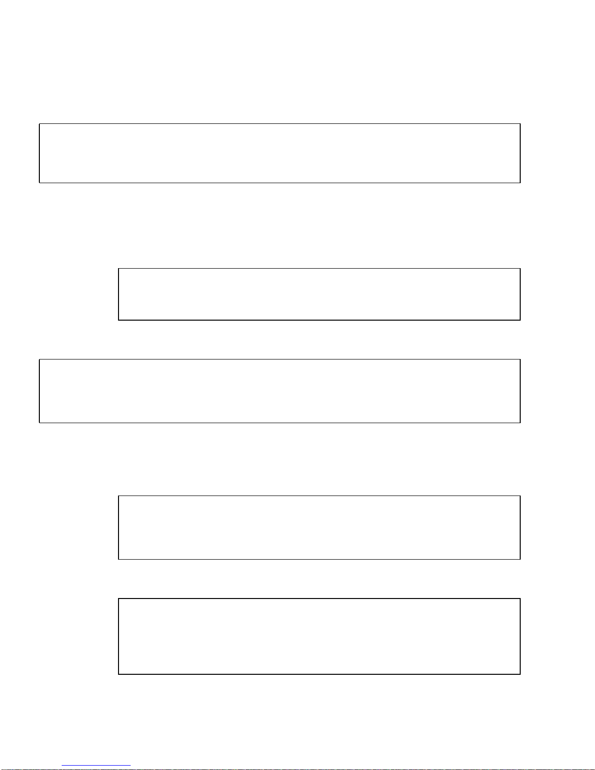
4. PVC/SVC mix: hosta uses an SVC to connect to hostb, and a PVC to connect to
hostc. hostb is not on the local switch; there is no ARP server.
Interface Host ATM Address VCI Flag
ba0 - $myaddress - l
ba0 hostb 45:00:00:00:00:00:00:00:0f:00:00:00:00:08:00:20:d5:08:a8:00 - t
ba0 hostc - 100 t
5. ARP server with access restrictions: Hosts are connected to an ATM ARP server
that resolves addresses. Access is restricted to the local switch subnet and one
additional switch subnet.
a. /etc/opt/SUNWconn/atm/aarconfig on hosta:
Interface Host ATM Address VCI Flag
ba0 - $myaddress - l
ba0 - $prefix:$sunmacsel0 - s
b. /etc/opt/SUNWconn/atm/aarconfig on server:
Interface Host ATM Address VCI Flag
ba0 - $prefix:$sunmacsel0 - L
ba0 - $prefix:$anymacsel - a
ba0 - 45:00:00:00:00:00:00:00:0f:00:00:00:00:$anymacsel - a
6. Manual address configuration: Hosts are connected to a switch that does not
support ILMI.
a. /etc/opt/SUNWconn/atm/aarconfig on server:
set prfx = 45:00:00:00:00:00:00:00:0f:00:00:00:00
Interface Host ATM Address VCI Flag
ba0 - $prfx:$sunmacsel0 - L
ba0 - - - m
b. /etc/opt/SUNWconn/atm/aarconfig on client:
set prfx = 45:00:00:00:00:00:00:00:0f:00:00:00:00
Interface Host ATM Address VCI Flag
ba0 - $prfx:$macsel - l
ba0 - $prfx:$sunmacsel0 - s
ba0 - - - m
52 SunATM 3U CompactPCI Adapter Installation and User’s Guide • February 2001

Configuring a LAN Emulation Interface
LAN Emulation, standardized by the ATM Forum’s LAN Emulation 1.0
specification, is another way of providing TCP/IP and UDP/IP support over an
ATM interface. Address resolution information is provided by a series of LAN
Emulation services. When a LAN Emulation interface is brought up, it must “join
the LAN;” that is, it must register with these services. This process, and the address
resolution process are described in “LAN Emulation” on page 69.
Unlike Classical IP, the LAN Emulation protocol provides a broadcast service to the
upper layer protocols. Therefore, the multicast and broadcast limitations described
in “Configuring a Classical Internet Protocol Interface” on page 44 do not affect LAN
emulation interfaces.
Editing the laneconfig File
The /etc/opt/SUNWconn/atm/laneconfig file contains the required
configuration information for each interface that uses LAN Emulation. One entry is
required for each SunATM interface.
Each time you modify the /etc/opt/SUNWconn/atm/laneconfig file, run the
LAN Emulation setup program (lanesetup). lanesetup is in the
/etc/opt/SUNWconn/atm/bin directory.
Each /etc/opt/SUNWconn/atm/laneconfig entry follows this format:
Interface MAC Address/ ATM Address VCI Flag
ELAN Name
Chapter 5 Editing SunATM Configuration Files 53

These entry fields are described in TABLE 5-5.
TABLE 5-5 /etc/opt/SUNWconn/atm/laneconfig Entry Descriptions
Field Description
Interface Refers to the LAN Emulation interface, laneN.
MAC Address/ELAN Name This field is for the 6-byte MAC address of the
interface, or, in the case of an n entry, the name of the
emulated LAN to join.
ATM Address This field is for the 20-byte ATM address. The
$myaddress variable assigns the local switch prefix,
local MAC address, and default selector.
VCI The VCI field is a positive decimal integer identifying
a Permanent Virtual Circuit. Place a dash in this field if
VCI is not used.
Flag This field identifies the type of entry. For a complete
description of the laneconfig flags, see
TABLE 5-6 describes the flags used in the /etc/opt/SUNWconn/atm/laneconfig
TABLE 5-6.
file.
TABLE 5-6 /etc/opt/SUNWconn/atm/laneconfig Flag Descriptions
Flag Description
l This flag designates a local address entry. There must be a l entry for each
interface running LAN Emulation. The interface and the ATM address must be
included; the MAC address may be included (default is the MAC address
assigned to the board).
t This flag designates a table entry for the local MAC-ATM address resolution
table. If you want to avoid the address resolution process for a frequently
accessed system, for instance, you may include a t entry for that system; you
may also create PVCs with a t entry. The interface, MAC address, and either
ATM address or VCI (for SVC or PVC connection, respectively) must be
included.
n This flag allows you to specify the name of an emulated LAN to join. By default,
the SunATM implementation will use the name provided by the LECS. If you
want to specify a different name, or if your LECS requires that a user include a
name in its requests, a name may be provided with this flag. Interface is
required; the name should be entered in the second field.
M Notifies the system that a larger MTU size will be used in the ELAN that this
lane instance will join. The default MTU size is 1500 bytes. With the M flag, you
can set the MTU size to be either 4 Kbytes (4528 bytes) or 9 Kbytes (9218 bytes).
54 SunATM 3U CompactPCI Adapter Installation and User’s Guide • February 2001

TABLE 5-6 /etc/opt/SUNWconn/atm/laneconfig Flag Descriptions (Continued)
Flag Description
a Represents an address that may have access to this host. If no a entries appear
in the laneconfig file, access to the host is unrestricted. Including a entries
allows access to be restricted to known hosts. As an alternative to listing
individual addresses, the ATM address field may contain a prefix, followed by
the wildcard $anymacsel, which matches any 7-byte ESI/Selector combination
following the given prefix. This allows access by any host connected to the
switch specified by the given prefix. Mac Address and VCI should not appear;
ATM Address is required. See
TABLE 5-7.
c This flag allows an alternate LECS address to be specified. By default, the
SunATM software uses the well-known address specified in the LAN Emulation
standard. If, however, your LECS has a different address, or you want to
connect to the LECS over a PVC, you may provide the alternate ATM address or
VCI in a c entry. If you want to make a PVC connection, the VCI must be 17, as
required by the LAN Emulation standard. The interface and ATM address or
VCI must be included.
s This flag specifies the LES address or VCI, and instructs the system to contact
the LES directly, and to use default subnet configuration information. This flag
should be used if your subnet does not have an LECS. Without this entry, the
system first connects to the LECS, which provides the LES address and
configuration information.
m Notifies the system that the entire ATM address, including the network prefix,
must be configured manually on this interface. If your interface is connected to
a switch that does not support ILMI address registration, you must include this
option in your or /etc/opt/SUNWconn/atm/laneconfig file. Note that the
variables $myaddress, $prefix, and $localswitch_server (which use the
switch prefix obtained from the switch via ILMI) may not be used if ILMI
address registration is disabled.
TABLE 5-7 describes the required, optional, and illegal fields for each flag type.
TABLE 5-7 laneconfig Flag Requirements and Options
Interface MAC Address/ELAN Name ATM Address VCI Flag
required optional required illegal l
required required xor
1
xor
1
t
required Emulated LAN name illegal illegal n
required MTU size in bytes illegal illegal M
required illegal required illegal a
required illegal xor
1
xor c
Chapter 5 Editing SunATM Configuration Files 55

TABLE 5-7 laneconfig Flag Requirements and Options (Continued)
Interface MAC Address/ELAN Name ATM Address VCI Flag
required illegal xor
required illegal illegal illegal m
1
xor means that you can use either the ATM Address field or the VCI field, but not both.
1
xor s
Note – Designate unused fields in the /etc/opt/SUNWconn/atm/laneconfig file
with a dash.
Using Variables in the laneconfig File
You can use some of the predefined variables from /etc/opt/SUNWconn/atm/
aarconfig file in the /etc/opt/SUNWconn/atm/laneconfig file. These
variables are listed in
variables, see “Using Variables in the aarconfig File” on page 47.
Note – Using predefined or user-defined variables in the MAC address field of local
(‘l’) entries is not supported. Variables may be used in the MAC address field of
other entry types, such as in table (‘t’) entries.
TABLE 5-8. For a complete description of how to use these
Note – You cannot use the $prefix variable, or any other variables that use it
(including $myaddress), on interfaces that are not using ILMI address registration.
TABLE 5-8 Predefined SunATM Variables
Variable Description
prefix The 13-byte prefix associated with the local switch.
mac The 6-byte MAC address associated with the local host or
interface.
sel The default 1-byte selector for the local interface.
macsel The concatenation of $mac:$sel.
myaddress The concatenation of $prefix:$mac:$sel, resulting in the
default address for the local interface.
56 SunATM 3U CompactPCI Adapter Installation and User’s Guide • February 2001
TABLE 5-8 Predefined SunATM Variables (Continued)
Variable Description
anymac A wild card representing any 6-byte ESI. Should only be used
in a entries.
anymacsel A wild card representing any 7-byte ESI and Selector
combination. Should only be used in a entries.
? A wild card matching one or two hexadecimal digits within
any colon-separated field. For example, $prefix:$anymac:?
is equivalent to both $prefix:$anymac:?? and
$prefix:$anymacsel. However, it is not the same as
$prefix:$anymacsel:0?, which requires that the first digit
of the selector byte is a 0. This wild card should only be used in
a entries.
Sample LAN Emulation Configurations
The following examples demonstrate entries in the /etc/opt/SUNWconn/atm/
laneconfig file for several common configurations.
Although some of the examples show only one sample laneconfig file, similarly
configured files must appear on each LAN Emulation client.
1. Basic LAN Emulation client. The ATM and MAC address of a frequently used
server is provided. The LECS provides the name of the Emulated LAN.
set srvr_mac = 08:00:20:01:02:03
Interface MAC_Address/ ATM_Address VCI Flag
ELAN Name
lane0 - $myaddress - l
lane0 $srvr_mac $prefix:$srvr_mac:00 - t
2. LAN Emulation client. The LECS requires that the client send the Emulated LAN
name in its messages.
Interface MAC_Address/ ATM_Address VCI Flag
ELAN Name
lane0 - $myaddress - l
lane0 elan1 - - n
Chapter 5 Editing SunATM Configuration Files 57

Supporting Multiple Emulated LANs
on a Single Interface
The SunATM software allows a single ATM interface to join up to 16 emulated local
area networks (ELANs), provided this is allowed by the switch and LAN Emulation
(LANE) services. Each ELAN joined will be represented by a unique lane instance
(for example, lane0 or lane1).
Note – A requirement for supporting this feature is that the adapter card be
assigned multiple MAC addresses, which is supported by the SunATM adapter. You
can find the number of MAC addresses assigned to your SunATM adapter by using
the atmgetmac(1M) command with the count option.
Configure multiple ELANs by placing multiple entries in the
/etc/opt/SUNWconn/atm/atmconfig and /etc/opt/SUNWconn/atm/
laneconfig files. Each lane instance will have a unique hostname and IP address,
ATM address, and MAC address associated with it. In addition, assign an ELAN
name to the instance if any ELAN other than the default is to be joined. Provide this
information, with the exception of the MAC address, which is retrieved from the
board itself, in the /etc/opt/SUNWconn/atm/atmconfig and /etc/opt/
SUNWconn/atm/laneconfig configuration files.
Note – Only one signalling protocol (for example, UNI 3.0 or 3.1) and one Classical
IP instance are supported per physical interface. Specify the UNI version in the first
/etc/opt/SUNWconn/atm/atmconfig entry for a given interface; the Classical IP
instance may be specified in any entry.
The following example shows the /etc/opt/SUNWconn/atm/atmconfig and
/etc/opt/SUNWconn/atm/laneconfig files and the ifconfig -a output for a
system with one SunATM interface, ba0. The interface uses UNI 3.0 for signalling,
and does not run Classical IP. It joins four emulated LANs: the default, elan1,
elan2, and elan3.
The example /etc/opt/SUNWconn/atm/atmconfig file:
Interface UNI CIP Hostname LANE Instance LANE Hostname
ba0 3.0 - 0 atm0
ba0 - - 1 atm1
ba0 - - 2 atm2
ba0 - - 3 atm3
58 SunATM 3U CompactPCI Adapter Installation and User’s Guide • February 2001

The corresponding example /etc/opt/SUNWconn/atm/laneconfig file:
Interface MAC Address/ ATM Address VCI Flag
ELAN Name
lane0 - $myaddress - l
lane1 - $myaddress - l
lane1 elan1 - - n
lane2 - $myaddress - l
lane2 elan2 - - n
lane3 - $myaddress - l
lane3 elan3 - - n
The resulting ifconfig -a output:
# ifconfig -a
lo0: flags=849<UP,LOOPBACK,RUNNING,MULTICAST> mtu 8232
inet 127.0.0.1 netmask ff000000
lane0:flags=863<UP,BROADCAST,NOTRAILERS,RUNNING,MULTICAST> mtu 1500
inet 192.29.240.36 netmask ffffff00 broadcast 192.29.240.255
ether 8:0:20:7a:37:af
lane1:flags=863<UP,BROADCAST,NOTRAILERS,RUNNING,MULTICAST> mtu 1500
inet 192.29.241.36 netmask ffffff00 broadcast 192.29.241.255
ether 8:0:20:7a:37:b0
lane2:flags=863<UP,BROADCAST,NOTRAILERS,RUNNING,MULTICAST> mtu 1500
inet 192.29.242.36 netmask ffffff00 broadcast 192.29.242.255
ether 8:0:20:7a:37:b1
lane3:flags=863<UP,BROADCAST,NOTRAILERS,RUNNING,MULTICAST> mtu 1500
inet 192.29.243.36 netmask ffffff00 broadcast 192.29.243.255
ether 8:0:20:7a:37:b2
Chapter 5 Editing SunATM Configuration Files 59

60 SunATM 3U CompactPCI Adapter Installation and User’s Guide • February 2001

CHAPTER
6
Plumbing and Unplumbing
SunATM Interfaces
This chapter describes how to start the SunATM software on your system or use the
atmifconfig utility to connect and disconnect individual SunATM interfaces
without rebooting the system.
Note – You only need to start the SunATM software on your system if you have just
installed the SunATM software and one or more SunATM adapters on your system.
If the software is already operating on your system, or if you have rebooted your
system you do not need to start the software manually.
This chapter contains the following sections:
■ “Starting the SunATM Software for the First Time” on page 62
■ “Plumbing and Unplumbing Individual ATM Interfaces” on page 62
61

Starting the SunATM Software for the
First Time
This section will describe how to use the drvconfig command and the S00sunatm
run control script to start up the SunATM software and load the driver module to
the system. When you reboot the system, these commands will be run and start the
software correctly.
Plumbing and Unplumbing Individual
ATM Interfaces
The atmifconfig utility allows interfaces to be added, modified, or removed
without rebooting the system by setting up and tearing down the streams necessary
to use an ATM device. This setting up and tearing down of streams is referred to as
plumbing and unplumbing.
The two required parameters for the utility are an interface name and plumbing
instructions. If an interface is being set up for native ATM applications (no TCP/IP)
or for Classical IP, the interface name should have the format ba
instance number. For LAN Emulation instances, the interface should have the format
laneN, where N is the LAN Emulation instance number.
N, where N is the
The second required parameter is the plumbing instruction. There are four possible
values: plumb, unplumb, plumb-all, and unplumb-all. The plumb and unplumb
options will set up or tear down the specified interface. The plumb-all and
unplumb-all options will set up or tear down all ATM instances on the specified
physical interface. In this case, the interface parameter must be a ba
this specifies the physical interface name. This will set up or tear down all the ATM
instances on this physical interface, including up to 16 LAN Emulation instances and
the Classical IP instance.
62 SunATM 3U CompactPCI Adapter Installation and User’s Guide • February 2001
N value, since

A summary of the parameter options for the atmifconfig utility is provided in
TABLE 6-1.
TABLE 6-1 Parameter Options for atmifconfig
Utility Interface Name Plumb Instruction
atmifconfig baN plumb
atmifconfig baN unplumb
atmifconfig laneN plumb
atmifconfig laneN unplumb
atmifconfig baN plumb-all
atmifconfig baN unplumb-all
The following example shows the use of atmifconfig and the output of
ifconfig -a before and after the utility is run.
# ifconfig -a
lo0: flags=849<UP,LOOPBACK,RUNNING,MULTICAST> mtu 8232
inet 127.0.0.1 netmask ff000000
ba0: flags=863<UP,BROADCAST,NOTRAILERS,RUNNING,MULTICAST> mtu 9180
inet 129.144.234.12 netmask ffffff00 broadcast 129.144.234.255
ether 8:0:20:84:e5:31
lane0: flags=863<UP,BROADCAST,NOTRAILERS,RUNNING,MULTICAST> mtu 1500
inet 129.144.161.12 netmask ffffff00 broadcast 129.144.161.255
ether 8:0:20:84:e5:31
# atmifconfig ba0 unplumb
# ifconfig -a
lo0: flags=849<UP,LOOPBACK,RUNNING,MULTICAST> mtu 8232
inet 127.0.0.1 netmask ff000000
lane0: flags=863<UP,BROADCAST,NOTRAILERS,RUNNING,MULTICAST> mtu 1500
inet 129.144.161.12 netmask ffffff00 broadcast 129.144.161.255
ether 8:0:20:84:e5:31
# atmifconfig lane0 unplumb
NOTICE: lane0: leaving ELAN
# ifconfig -a
lo0: flags=849<UP,LOOPBACK,RUNNING,MULTICAST> mtu 8232
inet 127.0.0.1 netmask ff000000
# atmifconfig ba0 plumb-all
q93b on ba0: Data Link Up
Configuring ATM interfaces: ba0
Configuring ATM LAN Emulation interfaces: lane0
Chapter 6 Plumbing and Unplumbing SunATM Interfaces 63

64 SunATM 3U CompactPCI Adapter Installation and User’s Guide • February 2001

CHAPTER
7
Classical IP and LAN Emulation
Protocols
This chapter describes ATM protocols and how they are supported by the SunATM
software. This chapter is composed of the following sections:
■ “ATM Network Protocols” on page 65
■ “ATM Addresses and Address Registration” on page 66
■ “Classical Internet Protocol” on page 67
■ “LAN Emulation” on page 69
ATM Network Protocols
ATM is a connection-oriented network protocol, which means that a connection
must be established between two communicating entities before data transfer can
begin. IP is inherently connectionless. The implementation on the host must
therefore reconcile the differences in these two paradigms.
There are two standard ways of doing this: Classical IP, standardized in RFC 1577,
and LAN Emulation, standardized in the LAN Emulation 1.0 specification from the
ATM Forum. The SunATM architecture supports both of these methods. This chapter
discusses some of the key ideas of these two methods.
Both methods allow IP to run transparently over the ATM interface. Thus IP itself
sees the ATM interface just as it sees any traditional network interface. Every
SunATM interface has a subnet IP address. As an ATM interface starts up,
appropriate modules and drivers are plumbed. All the TCP/IP and
UDP/IP applications run without modifications over these modules, and all the
utilities associated with the network interfaces also run without modification and
display similar results (for example, netstat and ifconfig utilities), with one
exception. Because of the different plumbing of the ATM modules, the plumb and
unplumb options of ifconfig will not work on ATM interfaces. The
atmifconfig(1M) command may be used to plumb and unplumb ATM interfaces.
IP treats the ATM interface as a subnet, choosing the interface used to send a packet
out based on the IP address of the destination and on the IP address and netmask of
the interface itself.
65

The transparency to IP is enabled in different ways in Classical IP and LAN
Emulation. Those differences will be discussed in later sections of this chapter.
SunATM signalling conforms to the user network interface (UNI) specification of the
ATM Forum. Versions 3.0, 3.1, and 4.0 of that specification are supported. This
signalling, called Q.2931, runs on top of QSAAL and uses VC 5 for signalling as
specified in the Forum specification.
ATM Addresses and Address
Registration
UNI signalling uses ATM addresses for signalling. Every ATM interface has an ATM
address in addition to its IP address.
ATM addresses, like Network Service Access Point (NSAP) addresses, are 20 octets
long. The End System Identifier (ESI) field within the ATM address is a unique
six-octet value; this can be the IEEE hardware MAC address conventionally
associated with every network interface. The Selector field is one octet long. The 13
octets that make up the rest of the ATM address are called the Network Prefix, and
are derived from the ATM switch fabric to which the interface is connected. Every
ATM switch fabric is configured with a 13-octet prefix.
On a SunATM host, the prefix associated with the local switch fabric is represented
by the $prefix variable. Its value is obtained by the system at configuration time.
1 octet
Determined by the ATM switch/13 ESI/6 octets SEL
FIGURE 7-1 ATM Address Fields
The UNI specification specifies the Interim Local Management Interface (ILMI)
service interface for a client to learn and register its ATM address. The ILMI service
interface is based on the use of SNMP over AAL5. In the SunATM software package,
ILMI service is provided by an address registration daemon, ilmid.
66 SunATM 3U CompactPCI Adapter Installation and User’s Guide • February 2001

ATM Address Registration Daemon (ilmid)
Address registration with a switch is controlled by ilmid. When an ATM interface
is brought up at boot time, ilmid is also started. ilmid then begins an exchange of
messages with the switch: relaying local address information (the seven-octet ESI
and selector) to the switch and receiving the 13-octet network prefix information
from the switch.
The default local address that is registered with the switch at boot time consists of
the network prefix provided by the switch, the MAC address assigned to the local
interface, and the default selector for that interface (usually 0). Additional addresses
are registered in two different ways. aarsetup(1M) and lanesetup(1M) register
additional local addresses that may appear in aarconfig(4) and laneconfig(4),
respectively. You can also use atmreg(1M) to register addresses, unregister
addresses, and check the status of any address.
Classical Internet Protocol
For ATM to work transparently under IP, an IP address must be resolved to an ATM
address and a connection to that destination must be established. Classical IP does
this via a database of IP/ATM address pairs that is either provided by an ATM ARP
server that is accessible to all hosts on the subnet, or is maintained locally in each
host.
ATM Address Resolution
Traditional TCP/IP and UDP/IP applications use IP addresses for communicating to
a destination. For these applications to run like traditional applications, IP addresses
need to be resolved into ATM addresses. The ATM address then signals to establish
an ATM connection to the destination. An ATM connection in turn is represented by
a VPI/VCI. The host must use this returned VPI/VCI to send packets to the
destination that represents the ATM connection.
ATM address resolution, also called ATM ARP, follows RFC 1577, the classic draft
that describes the ATM ARP process.
RFC 1577 assumes the existence of an ATM ARP server on every subnet. Every client
on the subnet communicates with the ATM ARP server to derive the destination’s
ATM address from its IP address. The ATM ARP server holds the IP-to-ATM address
information for all hosts in the ATM subnet. It is likely that initial ATM
configurations will not rely on dynamic ATM address resolution because it requires
the presence of an ATM ARP server on every subnet. Also, there are no specified
Chapter 7 Classical IP and LAN Emulation Protocols 67

standards for providing redundant ATM ARP servers for a subnet. As specified, the
ATM ARP server would constitute a single point of failure in the system. From a
practical standpoint, however, early configurations can use an IP-to-ATM address
database in every system, thus avoiding the IP-to-ATM address resolution step
altogether.
The RFC requires a router for passing data between subnets. SunATM software
provides ATM utilities that allow configurations to specify IP-to-ATM addresses in
/etc/opt/SUNWconn/atm/aarconfig files. The aarsetup program uses the
information in /etc/opt/SUNWconn/atm/aarconfig to create IP-to-ATM address
resolution tables. Dynamic entries into a server’s resolution table are also supported.
TABLE 5-2 shows the format of the /etc/opt/SUNWconn/atm/aarconfig file for
specifying the IP-to-ATM address. It is important for the file to be consistent on all
systems in the subnet. See “Editing the aarconfig File” on page 44.
ATM ARP Address Resolution Tables
Depending on the aarconfig file, the Classical IP software runs as either a server
or a client. As a server, the Classical IP software handles ATM ARP requests
originating from its clients. An ATM server has to be configured for each subnet. The
ATM ARP server code conforms to RFC 1577: clients send ATM ARP requests to the
server to resolve a destination IP address to an ATM address. The server then replies
to ATM ARP requests by sending an ATM ARP response. If the server does not have
the IP-to-ATM address entry, then it replies with NAK.
All the IP-to-ATM address entries specified in the /etc/opt/SUNWconn/atm/
aarconfig file are entered into a kernel resident table by the ATM ARP setup
program, aarsetup. Additional entries in the kernel table are added dynamically
using the inverse ARP process. When a client connects to the server, the server sends
an inverse ARP request back to the client to obtain the client’s IP address. When a
response is received, an entry is created for that client. The Classical IP software also
responds to client ARP requests. The software looks up a kernel IP-to-ATM address
entry and responds to an ATM ARP request with either an ATM ARP reply or ATM
ARP NAK (if there is no entry in the table). Note that an ATM ARP client uses the
virtual channel (VC) specified in the /etc/opt/SUNWconn/atm/aarconfig file to
communicate with the server; or, if an ATM address is specified, it establishes a
switched virtual circuit (SVC) connection to communicate with the server.
While dynamic entries in the ARP server’s table make network administration less
complex, they also create a security problem. Any host can register with the ARP
server and therefore gain access to the subnet. To resolve this issue, you can provide
a list of hosts or networks with a entries in the server’s
/etc/opt/SUNWconn/atm/aarconfig file. If no a entries appear, any host can
connect to the server. If any a entries exist, only those hosts whose addresses match
those specified will be allowed to connect.
68 SunATM 3U CompactPCI Adapter Installation and User’s Guide • February 2001

Although the a entry requires a complete ATM address, you can reference multiple
addresses in a single entry using the provided wildcards. See “Using Variables in the
aarconfig File” on page 47 for more information about this feature.
The advantage of having an ATM ARP server in the subnet is that it represents a
known source for all address resolutions. It is the only host that a client must know
about to have IP addresses resolved to ATM connections, and it allows for access
control in the ATM network.
When the /etc/opt/SUNWconn/atm/aarconfig file has been modified on a
system, it is necessary to rerun aarsetup.
Note – For better caching, all clients have the option of adding to their
configuration file the IP-to-ATM address information for other clients.
This can benefit clients that communicate frequently because it eliminates having to
go through the ATM ARP server for IP-to-ATM address resolution.
If a host has multiple SunATM cards, the host can be a server for one IP subnet and
a client for another. This is handled transparently by aarsetup.
LAN Emulation
As described in previous sections, Classical IP provides its own (IP-to-ATM) address
resolution mechanism that corresponds to and replaces ARP, thus allowing IP-based
applications to run transparently over ATM. A shortcoming of Classical IP, and a
primary reason it must replace the traditional ARP, is that it does not support
broadcast messages.
Because ATM is a connection-oriented protocol (unlike ethernet), implementing
broadcast is much more difficult. The only host that receives a message is the host to
which the message is addressed, and a call must be established to that host before
the message can be sent.
Local area network (LAN) Emulation, as standardized by the ATM Forum, provides
mechanisms to send broadcast messages in an ATM environment. Given this
capability, LAN Emulation is also able to work transparently with ARP, as well as IP.
IP and ARP send broadcast messages over the ATM interface, and thus resolve IP
addresses to MAC addresses; messages are then sent to the LAN Emulation driver,
which has its own address resolution protocol (similar to that of Classical IP) to
resolve the medium access control (MAC) address to an ATM address and
connection.
Chapter 7 Classical IP and LAN Emulation Protocols 69

The SunATM software implements the client side of the LAN Emulation standard.
To use LAN Emulation in an environment, several LAN Emulation services must
also exist in the emulated LAN. These services, called the LAN Emulation
Configuration Server (LECS), the LAN Emulation Server (LES), and the Broadcast
and Unknown Address Server (BUS), are generally provided in an ATM switch. The
following sections provide an overview of the functions of these servers.
LAN Emulation Servers
There are three types of LAN Emulation servers. Each type is briefly described in
this section.
LAN Emulation Configuration Server
This server is first contacted by a host interface when the host is brought up on the
emulated LAN. Its address is generally a well-known address specified by the LAN
Emulation standard that is coded into the host software; thus establishing this
connection requires no input from you. When contacted by a host wishing to join its
emulated LAN, the LECS replies with configuration parameters for the emulated
LAN, as well as the address of the LES.
LAN Emulation Server
The second step in joining an emulated LAN is to make a connection to the LAN
Emulation Server. After receiving the LES address from the LECS, a host will
establish a connection to the LES. The LES may add the host to a point-to-multipoint
call that is maintained by the LES with connections to every host in the emulated
LAN. This point-to-multipoint connection, if created by the LES, is used to send
control information to each host on the emulated LAN.
The LES acts as the ATM ARP server. Since IP and ARP work with MAC addresses,
an additional address resolution step is required to convert a MAC address to the
corresponding ATM address, which is used to make a connection to the target host;
this resolution step is provided by the LES.
Broadcast and Unknown Address Server
The final step in joining an emulated LAN is to make a connection to the BUS. The
ATM address of the BUS is obtained by sending a LAN Emulation ARP request to
the LES for the broadcast address. Once established, this connection is used to send
broadcast messages to the BUS, which will add the client to a point-to-multipoint
call including all hosts on the emulated LAN. Thus when a broadcast message (such
70 SunATM 3U CompactPCI Adapter Installation and User’s Guide • February 2001

as an IP ARP request) is received by the LAN Emulation host from its upper layers,
it sends that message to the BUS, which forwards it to all hosts in the emulated
LAN. Just as in the case of ethernet, the correct host responds to the sender, and thus
the IP address is resolved to a MAC address.
Resolving an IP Address to an ATM Connection
The entire process from the time IP sends a message addressed to an IP address to
the arrival of that message at the appropriate destination was hinted at in the
previous descriptions of the LAN Emulation servers. To demonstrate how those
pieces work together during the actual transmission of a message, the process is
described below. This description assumes that none of the needed addresses have
been previously resolved and cached. The two hosts involved are referred to as the
source (the system that wishes to send a message) and the target (the system to
which the message is addressed).
1. IP has a message to transmit and only knows the IP address of the target system.
IP first sends a message to ARP, to resolve the IP address to a MAC address.
2. ARP creates a broadcast request for the MAC address corresponding to the given
IP address, which it sends to the LAN Emulation driver.
3. The LAN Emulation driver recognizes that this message has a broadcast address,
and sends it to the BUS, which forwards the message to every host on the
emulated LAN.
4. The message is received on each host, and sent up to ARP by the LAN Emulation
driver.
5. On the target, ARP recognizes the IP address as its own and sends a response
with its MAC address (addressed to the source’s MAC address) down to the LAN
Emulation driver.
6. The LAN Emulation driver sends an LE ARP request to the LES to resolve the
source’s MAC address to its ATM address.
7. The LES responds with the requested ATM address, and the target host sets up an
ATM connection to the source host, over which it sends the IP ARP response.
8. The LAN Emulation driver on the source receives the IP ARP response message
and sends it up to ARP. ARP then inserts the MAC address into the original
message and sends it back down to the LAN Emulation driver.
9. The LAN Emulation driver then must send an LE ARP request to the LES to
resolve the MAC address in the message from ARP to an ATM address. When it
receives an LE ARP response, it then sees that it has a connection to that address
(established by the target to return the IP ARP response) and sends the original IP
message to the target over that connection.
Chapter 7 Classical IP and LAN Emulation Protocols 71

LAN Emulation Connections
There are several connections established at all times when a host is a member of an
emulated LAN. The following table outlines the various LAN Emulation-related
connections that should be on a LAN Emulation client (LEC).
Note – Use the command qccstat(1M) to view all existing connections for a given
interface.
TABLE 7-1 LAN Emulation Connections
VCC Endpoints Comments
Configuration Direct LEC —> LECS This connection is not required to remain open
after the initial join of the emulated LAN, and
thus may time out after a host has joined the
LAN.
Control Direct LEC —> LES Point-to-point connection over which the host
may send LE ARP requests and receive
responses from the LES.
Control Distribute LES —> LEC Point-to-multipoint connection over which the
LES may send administrative information to all
hosts. Hosts may not send on this connection.
Multicast Send LEC —> BUS Point-to-point connection over which the host
may send broadcast messages to the BUS. A
limited amount of data is also allowed on this
connection.
Multicast Forward BUS —> LEC Point-to-multipoint connection over which the
BUS sends broadcast messages. Hosts may not
send on this connection.
72 SunATM 3U CompactPCI Adapter Installation and User’s Guide • February 2001

CHAPTER
8
SunATM and Solaris Networking
Features
This chapter discusses the SunATM and Solaris Networking features.
This chapter includes the following sections:
■ ATM and SNMP on page 73
■ ATM and Logical Interfaces on page 75
ATM and SNMP
Two of the ATM standards supported by the SunATM software (the User Network
Interface (UNI) and LAN Emulation (LANE) specifications) include definitions of
SNMP-style Management Information Bases (MIBs) relevant to those standards.
These MIBs are referred to as the ATM Forum (ATMF) and LAN Emulation (LANE)
MIBs, respectively.
The ATM SNMP daemon (atmsnmpd) handles requests for information in both
MIBs, as well as the system MIBs, from SNMP-based network management systems
(such as the SunNet Manager program), and from ilmid, when it is required, for
SNMP requests coming from the switch.
atmsnmpd can be used as a forwarding agent. If you configure it as a forwarding
agent, atmsnmpd will forward SNMP requests for unknown MIBs to the port
specified with the forward option, -f. This allows a system to have two SNMP
agents respond to requests received over the SNMP port.
required configuration. To set up this example configuration, atmsnmpd must be
started with the parameter -f 1000 and other_snmpd must be started so that it
listens on port 1000.
FIGURE 8-1 illustrates the
73

SunATM Host
atmsnmpd
UDP
FIGURE 8-1 Using atmsnmpd as a Forwarding Agent
other_snmpd
1000161
Forwarding channel
Note – If you do not specify a forwarding port for unknown requests, atmsnmpd
will respond with a “No Such Name” error to requests for MIBs that it does not
support. If you do specify a forwarding port, atmsnmpd instead forwards the
request to that port. Responses received from the agent running on the forwarding
port are sent to the requesting SNMP manager with no modification. If the agent
does not respond, then atmsnmpd does not send a response back.
SNMP and Solaris
The ATM SNMP agent in SunATM supports a framework for SNMP agents;
however, this means that its setup depends on the version of the Solaris operating
environment in which it is running. This section discusses those differences, which
are mostly transparent to the user.
Solaris 2.6, Solaris 7, and Solaris 8 Compatible Software
The Solaris 2.6, 7, and 8 operating environments include a bundled SNMP agent that
is designed to run as a master agent, binding by default to UDP port 161. Configure
other agents to listen to other UDP ports and act as subagents, then configure the
master agent to forward particular requests to those subagents. This framework
provides a single agent at port 161 with the combined capabilities of the master
agent and all the additional subagents.
74 SunATM 3U CompactPCI Adapter Installation and User’s Guide • February 2001

The SunATM software has been designed to take advantage of this framework if it is
installed on a system running Solaris 2.6, 7, or 8. The files necessary for the ATM
SNMP agent to be recognized by the master agent (atm.reg and atm.rsrc)are
copied under /etc/snmp/conf by the S00sunatm startup script if it detects that
the system is running Solaris 2.6, 7, or 8. SNMP requests pertaining to the ATM
Forum subtree (atmForum) are forwarded to the atmsnmpd from the master agent.
In addition, atmsnmpd binds, by default, to port 1000, rather than 161, under Solaris
2.6 or later. The UDP port may still be changed using atmadmin, but the default will
be 1000 in Solaris 2.6, 7, or 8.
ATM and Logical Interfaces
The SunATM software supports logical interfaces in the LAN Emulation
environment. Logical interfaces allow you to assign multiple IP addresses to a single
Emulated LAN interface. A logical interface name consists of three parts: the device
name (in the case of SunATM LAN Emulation, lane); the major number, which
corresponds to the lane instance number; and the minor number, which
distinguishes the logical interfaces on a single physical interface. The format of a
LAN Emulation logical interface name is laneN:X, where N is the major number
and X is the minor number.
Each logical interface will be associated with a unique IP hostname and address. All
logical interfaces on a given physical interface will be associated with the same ATM
and MAC addresses. Configure logical interfaces by placing multiple entries for a
given interface in the /etc/opt/SUNWconn/atm/atmconfig file.
Consider the following rules when you use logical interfaces with the SunATM
software:
■ Only one signalling protocol (UNI 3.0, 3.1, or 4.0) is supported per interface, and
must appear in the first entry for that interface.
■ Only one Classical IP hostname may be assigned to an interface; it can appear in
any entry, in any order, in /etc/opt/SUNWconn/atm/atmconfig.
■ The first laneN entry on an interface must be for laneN:0, or simply laneN.
laneN and laneN:0 are identical and interchangeable.
■ IP limits the number of logical interfaces on a physical interface to 256
(the minor number X must be in the range 0 - 255) in Solaris 2.5.1, and to 8194
(the minor number X must be in the range0 - 8193) in Solaris 2.6 and later
releases.
Chapter 8 SunATM and Solaris Networking Features 75

The following examples show the atmconfig and laneconfig files and the
ifconfig -a output for a system with one physical interface, ba0. That interface
runs both Classical IP and LAN Emulation under UNI 3.1, and has 4 different IP
addresses. Configure the hostnames, cip0, atm0, atm1, and atm2, appropriately in
/etc/hosts.
The example /etc/opt/SUNWconn/atm/atmconfig file:
Interface UNI CIP Hostname LANE Instance LANE Hostname
ba0 3.1 cip0 0 atm0
ba0 - - 0:1 atm1
ba0 - - 0:2 atm2
The corresponding example /etc/opt/SUNWconn/atm/laneconfig file:
Interface MAC Address/ ATM Address VCI Flag
ELAN Name
lane0 - $myaddress - l
The resulting ifconfig -a output:
# ifconfig -a
lo0: flags=1000849<UP,LOOPBACK,RUNNING,MULTICAST,IPv4> mtu 8232 index 1
inet 127.0.0.1 netmask ff000000
ba0: flags=1000843<UP,BROADCAST,RUNNING,MULTICAST,IPv4> mtu 9180 index 3
inet 192.29.235.36 netmask ffffff00 broadcast 192.29.235.255
ether 8:0:20:7a:37:af
lane0: flags=1000843<UP,BROADCAST,RUNNING,MULTICAST,IPv4> mtu 1500 index 4
inet 192.29.240.36 netmask ffffff00 broadcast 192.29.240.255
ether 8:0:20:8b:6d:d0
lane0:1: flags=1000843<UP,BROADCAST,RUNNING,MULTICAST,IPv4> mtu 1500 index 4
inet 192.29.241.36 netmask ffffff00 broadcast 192.29.241.255
lane0:2: flags=1000843<UP,BROADCAST,RUNNING,MULTICAST,IPv4> mtu 1500 index 4
inet 192.29.242.36 netmask ffffff00 broadcast 192.29.242.255
76 SunATM 3U CompactPCI Adapter Installation and User’s Guide • February 2001

APPENDIX
A
Specifications
This appendix lists the specifications of the SunATM 3U compact PCI adapter.
Physical Dimensions
TABLE A-1 Physical Dimensions
Dimension Measurement
Length 160 mm
Width 100 mm
77

Performance Specifications
TABLE A-2 Performance Specifications
Feature Specification
cPCI clock 33MHz .
Maximum burst transfer rate 34 Mbytes/sec (approximately)
Steady state transfer rate 5 Mbytes/sec
cPCI bus modes Master/Slave
Power Specifications
TABLE A-3 Power Specifications
Specification Measurement
Power dissipation 8 Watt/33 MHz operation mode
Voltage tolerance +/- 5%
Ripple < = 100 mV
Operational current 1.6 Amps/33 MHz operation mode
Environmental Specifications
TABLE A-4 Environmental Specifications
Condition Operating Specification Storage Specification
Temperature 0 to 70 C (+32 to +131 F) -25 to 70 C(-25 to +131 F)
Relative humidity 5 to 85% non-condensing
(40 C,wet bulb temperature)
Altitude -1000 to +15,000 ft. -1000 to +50,000 ft.
0 to 95% non-condensing
40 C/hour
78 SunATM 3U CompactPCI Adapter Installation and User’s Guide • February 2001
 Loading...