


Sun Enterprise
™
6500/5500/4500 Systems
Installation Guide
Sun Microsystems, Inc.
901 San Antonio Road
Palo Alto, CA 94303
U.S.A. 650-960-1300
Part No. 805-2631-11
August 2001 , Revision A
Send comments about this document to: docfeedback@sun.com

Copyright 2001Sun Microsystems, Inc.,901 SanAntonio Road,Palo Alto,CA 94303-4900U.S.A. Allrights reserved.
This product ordocument isdistributed underlicenses restrictingits use,copying, distribution,and decompilation.No partof thisproduct or
document may be reproduced inany formby anymeans withoutprior writtenauthorization ofSun andits licensors,if any.Third-party
software,including fonttechnology,is copyrightedand licensedfromSun suppliers.
Parts of the product maybe derivedfrom BerkeleyBSD systems,licensed fromthe Universityof California.UNIX isa registered trademark in
the U.S. and other countries, exclusively licensed through X/OpenCompany,Ltd.
Sun, Sun Microsystems,the Sunlogo, AnswerBook,AnswerBook2, docs.sun.com,Sun Enterprise,OpenBoot, JumpStart,Solstice SunNet
Manager,Sun StorEdge, and Solaris aretrademarks, registeredtrademarks, orservice marksof Sun Microsystems,Inc. inthe U.S.and other
countries. All SPARC trademarks areused underlicense andare trademarksor registeredtrademarksof SPARC International, Inc. in theU.S.
and other countries. Products bearingSPARCtrademarks arebased uponan architecture developed by Sun Microsystems,Inc.
The OPEN LOOK and Sun™ Graphical User Interface was developed bySun Microsystems,Inc. forits usersand licensees.Sun acknowledges
the pioneering effortsof Xeroxin researchingand developing the concept of visual orgraphical userinterfaces forthe computerindustry.Sun
holds a non-exclusive license fromXerox tothe XeroxGraphical UserInterface, whichlicense alsocovers Sun’s licensees who implement OPEN
LOOK GUIs and otherwise comply with Sun’s written license agreements.
Federal Acquisitions: CommercialSoftware—Government UsersSubject toStandard LicenseTerms andConditions.
Sun Microsystems, Inc.has intellectualproperty rightsrelating totechnology embodiedin thisproduct.In particular, andwithout limitation,
these intellectual propertyrights mayinclude oneor moreof theU.S. patentslisted athttp://www.sun.com/patentsand one or more
additional patents or pending patent applications in the U.S. and other countries.
DOCUMENTATION IS PROVIDED “AS IS” AND ALL EXPRESS OR IMPLIED CONDITIONS, REPRESENTATIONS AND WARRANTIES,
INCLUDING ANYIMPLIED WARRANTYOF MERCHANTABILITY,FITNESS FOR A PARTICULARPURPOSE OR NON-INFRINGEMENT,
ARE DISCLAIMED, EXCEPT TO THE EXTENT THAT SUCH DISCLAIMERS ARE HELD TO BE LEGALLY INVALID.
Copyright 2001 Sun Microsystems, Inc.,901 SanAntonio Road,Palo Alto,CA 94303-4900Etats-Unis. Tousdroits réservés.
Ce produit oudocument estdistribué avecdes licencesqui enrestreignent l’utilisation,la copie,la distribution,et la décompilation. Aucune
partie de ce produit oudocument nepeut êtrereproduitesous aucuneforme, parquelque moyenque cesoit, sansl’autorisation préalableet
écrite de Sun et de ses bailleurs de licence, s’il y en a.Le logicieldétenu pardes tiers,et quicomprend latechnologie relativeaux policesde
caractères,est protégépar uncopyright etlicencié pardes fournisseursde Sun.
Des parties de ce produitpourront êtredérivées dessystèmes BerkeleyBSD licenciéspar l’Universitéde Californie.UNIX estune marque
déposée aux Etats-Unis et dans d’autres payset licenciéeexclusivement parX/Open Company,Ltd.
Sun, Sun Microsystems,le logoSun, AnswerBook,AnswerBook2, docs.sun.com,Sun Enterprise,OpenBoot, JumpStart,Solstice SunNet
Manager,Sun StorEdge, et Solaris sont des marquesde fabriqueou desmarques déposées,ou marquesde service, de Sun Microsystems,Inc.
aux Etats-Unis et dans d’autrespays. Toutesles marquesSPARCsont utiliséessous licenceet sontdes marques defabrique oudes marques
déposées de SPARC International, Inc. aux Etats-Unis et dans d’autres pays.Les produitsportant lesmarques SPARCsont baséssur une
architecturedéveloppée parSun Microsystems,Inc.
L’interfaced’utilisation graphique OPEN LOOK et Sun™ a été développéepar SunMicrosystems, Inc.pour sesutilisateurs etlicenciés. Sun
reconnaîtles effortsde pionniersde Xeroxpour larechercheet ledéveloppement duconcept desinterfaces d’utilisationvisuelle ougraphique
pour l’industrie de l’informatique. Sun détient une licence non exclusive deXerox surl’interface d’utilisationgraphique Xerox,cette licence
couvrant également les licenciés de Sun qui mettent en place l’interfaced’utilisation graphiqueOPEN LOOKet quien outrese conformentaux
licences écrites de Sun.
Sun Microsystems, Inc.a lesdroits depropriété intellectuelsrelatantsà latechnologie incorporéedans ceproduit. Enparticulier,et sansla
limitation, ces droitsde propriétéintellectuels peuventinclure unou plusdes brevetsaméricainsénumérés àhttp://www.sun.com/patentset
un ou les brevets plussupplémentaires oules applicationsde breveten attentedans lesEtats -Unis etles autres pays.
LA DOCUMENTATIONEST FOURNIE “EN L’ETAT” ET TOUTESAUTRES CONDITIONS, DECLARATIONS ET GARANTIES EXPRESSES
OU TACITES SONT FORMELLEMENTEXCLUES, DANSLA MESUREAUTORISEE PARLA LOIAPPLICABLE, YCOMPRIS NOTAMMENT
TOUTE GARANTIE IMPLICITE RELATIVE A LA QUALITE MARCHANDE, A L’APTITUDE A UNE UTILISATION PARTICULIERE OU A
L’ABSENCE DE CONTREFAÇON.
Please
Recycle

Contents
1. Preparing for Installation 1-1
1.1 Unpacking the Enterprise 6500/5500 Cabinet Systems 1-2
1.1.1 Shipping and Storing the System 1-4
1.2 Preparing the Electrical Circuits 1-5
1.2.1 Enterprise 6500/5500 Cabinet Systems 1-5
1.2.2 Enterprise 4500 System 1-6
1.3 Preparing the Air Conditioning 1-6
1.4 Preparing the Ethernet Network 1-7
1.5 Preparing the Area 1-9
1.5.1 Enterprise 6500/5500 Cabinet Systems 1-9
1.5.2 Enterprise 4500 System 1-10
1.6 Preparing the Enterprise 6500/5500 Cabinet Systems 1-11
1.6.1 Moving the Server 1-11
1.6.2 Adjusting the Levelling Pads 1-12
1.7 Adding Storage Devices 1-14
1.8 Preparing the Enterprise 4500 System 1-15
1.9 Using the User Naming Area 1-15
2. Cabling the System 2-1
2.1 Preparing the System for Cabling 2-1
Contents iii

2.2 Removing and Replacing the Enterprise 6500/5500 Cabinet Rear Door and
Kick Panel 2-1
2.2.1 Removing the Rear Door and Kick Panel 2-1
2.2.2 Replacing the Rear Door and Kick Panel 2-3
2.3 Connecting the Power Cords 2-3
2.3.1 Enterprise 6500/5500 System Power Cord 2-3
2.3.2 Enterprise 4500 System Power Cord 2-4
2.4 Connecting the Network Cable to the System 2-5
2.5 Connecting the System to the Network 2-6
2.6 Connecting an ASCII Terminal 2-9
2.7 Connecting the Fiber Cable to the I/O+ Board 2-10
2.8 Connecting External SCSI Devices 2-12
3. Powering the System On and Off 3-1
3.1 Using JumpStart Automatic Installation 3-1
3.2 Enterprise 6500/5500 Cabinet Systems 3-2
3.2.1 Powering On the System 3-2
3.2.2 Reading Boot Messages 3-6
3.2.3 Interpreting Status LED Patterns 3-7
3.2.4 Powering Off the System 3-8
3.3 Enterprise 4500 System 3-9
3.3.1 Powering On the System 3-9
3.3.2 Reading Boot Messages 3-12
3.3.3 Interpreting Status LED Patterns 3-13
3.3.4 Powering Off the System 3-14
3.4 Failure of Network Communications 3-15
4. Software 4-1
4.1 Operating System Software and Patches 4-1
4.2 Sun™ Management Center Software 4-1
4.3 Dynamic Reconfiguration for Hot-Pluggable System Boards 4-2
iv Sun Enterprise 6500/5500/4500 Systems Installation Guide • August 2001

4.4 CPU Over-Temperature Safeguard (COS) 4-2
A. Regulatory Agency Compliance Statements A-1
A.1 FCC Class A Notice A-2
A.2 FCC Class B Notice A-3
A.3 DOC Class A Notice – Avis DOC, Classe A A-4
A.4 DOC Class B Notice – Avis DOC, Classe B A-4
A.5 BSMI Class A Notice A-5
Contents v

vi Sun Enterprise 6500/5500/4500 Systems Installation Guide • August 2001

Figures
FIGURE 1-1 Enterprise 6500/5500/4500 Systems 1-1
FIGURE 1-2 Attaching the Ramps to the Shipping Pallet 1-4
FIGURE 1-3 Types of Network Cables Used 1-7
FIGURE 1-4 Example of 10/100BASE-T (Twisted-Pair) Ethernet 1-8
FIGURE 1-5 Cabinet Server Access Areas — Top View 1-9
FIGURE 1-6 Standalone Server Access Areas — Top View 1-10
FIGURE 1-7 Moving the Server Safely Down the Ramps 1-12
FIGURE 1-8 Levelling Pad 1-13
FIGURE 1-9 Stabilizer Bar 1-14
FIGURE 2-1 Key Switch Standby Position 2-2
FIGURE 2-2 AC Power Sequencer Power Switch 2-2
FIGURE 2-3 Key Switch Positions 2-4
FIGURE 2-4 AC Power Switch and Power Receptacle 2-4
FIGURE 2-5 Network Cable 2-5
FIGURE 2-6 10/100BASE-T Ethernet Connection 2-6
FIGURE 2-7 Connecting Twisted Pair Ethernet to N-type Coaxial Cable 2-7
FIGURE 2-8 Ethernet Cabling Length — Example Using N-type Cable 2-8
FIGURE 2-9 Clock+ Board 2-9
FIGURE 2-10 Fiber Cable and Fiber Card Connectors and Ports on the I/O+ Board 2-11
Figures vii

FIGURE 2-11 Onboard Single-ended SCSI Connector on the I/O+ Board 2-13
FIGURE 3-1 Key Switch on the Enterprise 6500/5500 3-3
FIGURE 3-2 Switches on the AC Power Sequencer 3-4
FIGURE 3-3 Reset Switches on the Clock+ Board 3-6
FIGURE 3-4 System Status LEDs (Cabinet Server) 3-7
FIGURE 3-5 Key Switch on the Enterprise 4500 3-10
FIGURE 3-6 AC Power Switch on the Enterprise 4500 3-11
FIGURE 3-7 Reset Switches on the Clock+ Board 3-12
FIGURE 3-8 System Status LEDs (Standalone Server) 3-13
viii Sun Enterprise 6500/5500/4500 Systems Installation Guide • August 2001

Tables
TABLE 2-1 Ethernet Cabling Limitations for N-type Coaxial Cable 2-8
TABLE 2-2 Internal SCSI Lengths (Approximate) 2-12
TABLE 3-1 Key Switch Positions 3-3
TABLE 3-2 Front Panel LED Status Indicators 3-7
TABLE 3-3 Key Switch Positions 3-10
TABLE 3-4 Front Panel LED Status Indicators 3-13
Tables ix

x Sun Enterprise 6500/5500/4500 Systems Installation Guide • August 2001

Preface
The Sun Enterprise™ 6500/5500/4500 Systems Installation Guide provides installation
instructions for factory-configured 16-slot and 8-slot cabinet and standalone server
systems. These instructions are for an experienced system administrator with
networking knowledge.
UNIX Commands
This document may not contain information on basic UNIX®commands and
procedures such as shutting down the system, booting the system, and configuring
devices.
See one or more of the following for this information:
■ Solaris Operating Environment Handbook for SMCC Peripherals which contains
Solaris Operating Environment software commands
■ AnswerBook2™ online documentation for the Solaris operating environment
software environment
■ Other software documentation that you received with your system
Preface xi

Typographic Conventions
TABLE P-1 Typographic Conventions
Typeface Meaning Examples
AaBbCc123 The names of commands, files,
and directories; on-screen
computer output
AaBbCc123
AaBbCc123 Book titles, new words or
What you type, when
contrasted with on-screen
computer output
terms, words to be emphasized
Command-line variable;
replace with a real name or
value
Shell Prompts
TABLE P-2 Shell Prompts
Edit your.login file.
Use ls -a to list all files.
% You have mail.
% su
Password:
Read Chapter 6 in the User ’s Guide.
These are called class options.
You must be superuser to do this.
To delete a file, type rm filename.
Shell Prompt
C shell machine_name%
C shell superuser machine_name#
Bourne shell and Korn shell $
Bourne shell and Korn shell superuser #
xii Sun Enterprise 6500/5500/4500 Systems Installation Guide • August 2001

Related Documentation
The following documents contain topics that relate to the information
in the Sun Enterprise 6500/5500/4500 Systems Installation Guide.
TABLE P-3 Related Documents
Application Title Part Number
Service Sun Enterprise 6500/5500/4500 Systems Reference Manual 805-2632
Software SMCC SPARC Hardware Platform Guide 802-5341
Sun Management Center User ’s Guide 802-5355
Dynamic
Reconfiguration User’s Guide
for Sun Enterprise 6x00/5x00/4x00/3x00 Systems 805-3530
Options Sun Enterprise Expansion Cabinet Installation and Service Manual 805-4009
Sun Enterprise 6/5/4/3x00 Board Installation Guide 805-4007
4 Mbyte UltraSPARC II Installation Guide 805-1150
Sun Enterprise xx00 Systems CPU Module Installation for 400-MHz
8-Mbyte CPU Module
Sun Enterprise xx00 Systems CPU Module Installation for 464-MHz
8-Mbyte CPU Module
SBus+ and Graphics+ I/O Boards (100 MB/sec Fibre Channels) for Sun
Enterprise 6/5/4/3x00 Systems 805-2704
PCI+ I/O Board Installation and Component Replacement for Sun
Enterprise 6/5/4/3x00 Systems 805-1372
Sun Enterprise Systems Peripheral Power Supply Installation Guide 802-5033
Sun Enterprise Systems Power/Cooling Module Installation Guide 802-6244
Sun Enterprise Cabinet Floor Brackets Mounting Guide 802-7543
Sun Enterprise Caster Base Installation Guide 802-5034
806-0960
816-1994
Sun Enterprise 6x00/5x00/4x00/3x00 Capacity-on-Demand (COD) Building
Blocks User’s Guide 806-4592
Rackmount Placement Matrix web site at docs.sun.com
Preface xiii

Accessing Sun Documentation Online
A broad selection of Sun system documentation is located at the following web site:
http://www.sun.com/products-n-solutions/hardware/docs
To locate the most current documentation at this site, select a product category. The
documents at that location may include updated information that did not ship with
your product, such as product notes, release notes, late-breaking news, or later
revisions of manuals.
Ordering Sun Documentation
Fatbrain.com, an Internet professional bookstore, stocks select product
documentation from Sun Microsystems, Inc.
For a list of documents and how to order them, visit the Sun Documentation Center
on Fatbrain.com at:
http://www.fatbrain.com/documentation/sun
Sun Welcomes Your Comments
Sun is interested in improving its documentation and welcomes your comments and
suggestions. You can email your comments to Sun at:
docfeedback@sun.com
Please include the part number (805-2631-10) of your document in the subject line of
your email.
xiv Sun Enterprise 6500/5500/4500 Systems Installation Guide • August 2001

Notes, Cautions, and Warnings
Caution – This equipment contains lethal voltage. Accidental contact with
centerplane, card cage, and drive areas can result in serious injury or death.
Caution – Improper handling by unqualified personnel can cause serious damage
to this equipment. Unqualified personnel who tamper with this equipment may be
held liable for any resultant damage to the equipment.
Individuals who remove any outer panels or open covers to access this equipment
must observe all safety precautions and ensure compliance with skill level
requirements, certification, and all applicable local and national laws.
Procedures contained in this document must be performed by qualified servicetrained maintenance providers.
Note – Before you begin, carefully read each of the procedures in this manual. If
you have not performed similar operations on comparable equipment, do not
attempt to perform these procedures.
Preface xv

xvi Sun Enterprise 6500/5500/4500 Systems Installation Guide • August 2001

CHAPTER
1
Preparing for Installation
This chapter describes how to prepare your site for these systems:
■ Sun Enterprise 6500 system—16-slot cabinet server
■ Sun Enterprise 5500 system— 8-slot cabinet server
■ Sun Enterprise 4500 system— 8-slot standalone server
■ Sun Enterprise 4500 system— 8-slot Rack-Ready server
Enterprise 6500 system (16 slots)
Enterprise 5500 system (8 slots)
FIGURE 1-1 Enterprise 6500/5500/4500 Systems
Enterprise Rack-Ready 4500 system
(8 slots)
Enterprise 4500 standalone enclosure (8 slots)
1-1

The tasks for installing the systems are:
■ Unpacking the cabinet server on page 1-2
■ Preparing the servers on page 1-6
■ Preparing the site on page 1-9
■ Cabling on page 2-1
■ Powering on on page 3-1
■ Using the softwareon page 4-1
Note – For information about physical specifications, electrical specifications, and
environmental requirements, refer to Appendix A, “Specifications,” in the Sun
Enterprise 6500/5500/4500 Systems Manual.
1.1 Unpacking the Enterprise 6500/5500
Cabinet Systems
Note – Inspect all shipping cartons for evidence of physical damage. If a shipping
carton is damaged, request that the carrier’s agent be present when the carton is
opened. Keep all contents and packing material for the agent’s inspection.
If you have a standalone Enterprise 4500 system, or the cabinet is already unpacked,
go to Section 1.2 “Preparing the Electrical Circuits.”
Note – Any unpacking instructions printed on the outside of the shipping carton
take precedence over instructions in this section.
Caution – If your cabinet system is on a wooden pallet, extend the cabinet levelling
pads so that the cabinet cannot roll. If the original shipping pallet has side rails, it is
not necessary to lower the levelling pads.
1. Cut the plastic or metal straps that are around the shipping container and lift off
the corrugated top.
Store the shipping materials for future shipments.
2. Remove the sides of the container.
The container is held together by six plastic clips. To unlock a clip, press the two
inner tabs together and pull out the entire clip.
1-2 Sun Enterprise 6500/5500/4500 Systems Installation Guide • August 2001

3. Remove inner packing materials from the top and corners of the cabinet.
4. At the front of the pallet, lift the Velcro™ strip at each end of the wooden bar to
detach the bar, then set it aside.
5. Slide out the two wooden ramps from under the cabinet.
6. Attach the wooden ramps to the pallet using the Velcro strip that is attached to
each ramp.
Ensure both wheel guides (wooden strips) are to the outside. See
FIGURE 1-2.
Caution – Three or more people are needed to move the server cabinet safely. Two
people must push at the front of the cabinet to control the movement of the cabinet.
Caution – To prevent the cabinet from tipping over, push or pull only on the upper
half of the cabinet.
Chapter 1 Preparing for Installation 1-3

Adhesive strip
Wheel guide
FIGURE 1-2 Attaching the Ramps to the Shipping Pallet
1.1.1 Shipping and Storing the System
Save the original shipping containers and packing materials in case you need to
store or ship your system.
If you cannot store the shipping materials, recycle or dispose of the materials
properly. Consult your local recycling authority for information.
1-4 Sun Enterprise 6500/5500/4500 Systems Installation Guide • August 2001

1.2 Preparing the Electrical Circuits
In planning where to place your equipment, remember that each of the following
items requires access (by way of a separate power cord) to a power outlet:
■ Sun Enterprise 6500/5500/4500 system
■ External peripherals
■ Monitor used for diagnostics
1.2.1 Enterprise 6500/5500 Cabinet Systems
The 16-slot and 8-slot system cabinets require a 30A circuit and a detachable cable.
The equipment relies on the protective device in the building installation, thus it
requires a 30A circuit breaker.
Caution – Do not attach other electrical equipment to the server AC circuit; server
reliability may be affected.
Note – If the appropriate electrical receptacle is not available in your country, the
connect may be removed from the cord. The cord can then be permanently
connected to a dedicated branch circuit by a qualified electrician. Check local
electrical codes for proper installation requirements.
Caution – The system cabinet has a high leakage current to ground. Strictly observe
the following instructions to reduce the risk of electric shock.
The system requires an electrical circuit that is grounded to earth. The UL1950,
CSA950, and EN60950 specify:
An insulated earthing conductor that is identical in size, insulation
material, and thickness to the earthed and unearthed branch-circuit
supply conductors, except that it is green with or without one or more
yellow stripes, is to be installed as part of the branch circuit that supplies
the unit or system. The earthing conductor described is to be connected
to earth at the service equipment or, if supplied by a separately derived
system, at the supply transformer or motor-generator set.
Chapter 1 Preparing for Installation 1-5

The attachment-plug receptacles in the vicinity of the unit or system are
all to be of an earthing type, and the earthing conductors serving these
receptacles are to be connected to earth at the service equipment.
The power cord provides a ground path that will protect the drives and boards in
the cabinet from static electricity damage.
Caution – Do not make mechanical or electrical modifications to the server cabinet.
Sun Microsystems® is not responsible for the regulatory compliance if the cabinet is
modified.
1.2.2 Enterprise 4500 System
The 8-slot Enterprise 4500 system uses nominal input voltages of 100-120 VAC or
200-240 VAC. Sun products are designed to work with single-phase power systems
having a grounded neutral conductor.
To reduce the risk of electrical shock, do not connect Sun products into another type
of power source. Contact your facilities manager or a qualified electrician if you are
unsure what type of power is supplied to your building.
1
1.3 Preparing the Air Conditioning
For the most reliable system operation:
■ The room should have sufficient air-conditioning capacity to support the cooling
needs of the entire system.
■ The air-conditioning system should have controls that prevent excessive
temperature changes.
1. InformationTechnologyEquipment —UL 1950,copyright 1989, 1991 by UnderwritersLaboratories, Inc.
1-6 Sun Enterprise 6500/5500/4500 Systems Installation Guide • August 2001

1.4 Preparing the Ethernet Network
The Enterprise 6500/5500/4500 systems follow the IEEE standard for 10/100BASE-T
Ethernet (twisted-pair) or MII (Media Independent Interface).
Twisted-pair cables used with Sun Microsystems products have RJ-45 connectors
that resemble the smaller RJ-11 connectors used for modular telephone cables. For
twisted-pair cable length, see Chapter 2,
A MII to AUI converter cable, available from Sun, enables the 10/100 Mbps Ethernet
interface to run over 10 Mbps coaxial Ethernet networks. Other MII Ethernet
connectivity products are available from third parties.
FIGURE 1-3 and FIGURE 1-4 illustrate types of network cables and possible
implementations of 10/100BASE-T Ethernet.
Set up the network using Sun or third-party components. To obtain the best results,
read any applicable manufacturer instructions. Be aware that Sun Microsystems
cannot guarantee the performance of any components that are not purchased from
Sun.
TABLE 2-1 on page 2-8.
Ethernet cable
Transceiver
Transceiver drop cable
(coaxial or optical fiber)
FIGURE 1-3 Types of Network Cables Used
Hardware interface
Vampire tap or N-type connectors
10/100BASE-T
twisted-pair cable
Server
Chapter 1 Preparing for Installation 1-7

Coaxialcableor
optical fiber
Network cable
Tap
Concentrator hub
Workstation
Server
Twisted-pair cable
FIGURE 1-4 Example of 10/100BASE-T (Twisted-Pair) Ethernet
Tap
Concentrator hub
Note – Multiplexer boxes require a transceiver when used with the Ethernet
applications described in this manual. Although these transceivers are compatible
with Sun equipment, Sun Microsystems does not guarantee the performance of any
component that was not purchased from Sun.
Many transceivers are compatible with both level-1 and level-2 Ethernet. To operate
these transceivers with Sun equipment, set the device for level-2 operation following
the manufacturer’s instructions.
Sun equipment conforms to the Ethernet 10/100BASE-T standard, which states that
the 10/100BASE-T Link Integrity Test function should always be enabled on both the
host and the hub. If you have problems verifying connection between Sun
equipment and your hub, verify that your hub also has the link test function
enabled. See Section 3.4 “Failure of Network Communications,” and refer to the
manual provided with your hub.
1-8 Sun Enterprise 6500/5500/4500 Systems Installation Guide • August 2001

1.5 Preparing the Area
1.5.1 Enterprise 6500/5500 Cabinet Systems
■ Server cabinets require approximately 4 feet (120 cm) of space in front and 3 feet
(90 cm) in back (
■ Server and expansion cabinets can be placed next to each other, without space
between them, since there are no side clearance requirements during operation.
To access and remove side panels, however, allow approximately 1 foot (30 cm) of
space on the sides.
■ The server system (including expansion cabinets) should have a dedicated AC
breaker panel. The server system should not share this breaker panel with other,
unrelated equipment.
■ Keep power and interface cables out of the way of foot traffic. Cables can be
routed inside walls, floors, ceilings, or in protective channels. Interface cables
should be routed away from motors and other sources of electric/magnetic or
radio frequency interference.
■ If the cabinet is installed on a raised floor, conditioned air should be directed to
the bottom of each rack through perforated panels.
FIGURE 1-5) for access by service personnel.
Tape/disk
EXP
■ Refer to the Sun Microsystems Data Center Site Planning Guide, Data Centers’ Best
Practices (805-5863) for more information on the recommended optimal operating
environment.
3 feet access at rear
1 foot, at left
and right sides
(for access only)
System
Tape/disk
EXP
FIGURE 1-5 Cabinet Server Access Areas — Top View
Tape/disk
EXP
4 feet access at front
cabinet
Tape/disk
EXP
NOTE: During operation, system and expansion
cabinets can be side by side –with 0 clearance–
since there are no side clearance requirements.
Tape/disk
EXP
Tape/disk
EXP
Chapter 1 Preparing for Installation 1-9

1.5.2 Enterprise 4500 System
The Enterprise 4500 system is designed to sit on the floor, on a caster base, or on a
desk or table.
Note – Do not stack multiple Enterprise 4500 systems directly on top of each other.
Follow these guidelines to prepare a location.
■ The server unit requires approximately 1.5 feet (50 cm) of space in the front and
back for access by service personnel (
■ A minimum space of 6 inches (16 cm) is required on both sides of the server to
afford adequate air flow.
■ A minimum space of 3 feet (91 cm) is recommended to avoid exhaust air
recirculation if systems are placed next to each other.
Caution – To avoid recirculating exhaust air from one system into another, do not
put systems or peripherals side by side closer than 3 feet (91 cm).
■ Keep power and interface cables clear of foot traffic. Route cables inside walls,
under the floor, through the ceiling, or in protective channels. Route interface
cables away from motors and other sources of magnetic or radio frequency
interference.
FIGURE 1-6).
■ Refer to the Sun Microsystems Data Center Site Planning Guide, Data Centers’ Best
Practices (805-5863) or the Thermal Guidelines for Mounting Sun Products in a NonSun Cabinet (805-1454) for more information on the recommended optimal
operating system environment.
on each side
* 3 feet on each side if systems or peripherals
are placed next to each other, side by side
FIGURE 1-6 Standalone Server Access Areas — Top View
1.5 feet access at rear
6 inches*
Standalone
system
1.5 feet access at front
1-10 Sun Enterprise 6500/5500/4500 Systems Installation Guide • August 2001

1.6 Preparing the Enterprise 6500/5500
Cabinet Systems
You need the following tools:
■ No. 1 Phillips screwdriver
■ Levelling wrench (packed inside the system cabinet)
■ Front panel key (packed in a bag in the accessory box)
1.6.1 Moving the Server
The server weighs at least 835 pounds (375 kg). Observe the following precautions
when moving the server.
Caution – Three or more people are needed to move the server cabinet safely. Two
people must push at the front of the cabinet to control the movement of the cabinet
(FIGURE 1-7).
Caution – To prevent the cabinet from tipping over, push or pull only on the upper
half of the cabinet.
Chapter 1 Preparing for Installation 1-11

FIGURE 1-7 Moving the Server Safely Down the Ramps
1.6.2 Adjusting the Levelling Pads
After moving the cabinet to its operating location, adjust the levelling pads.
1. Remove the levelling wrench from inside the server cabinet.
The levelling wrench is attached to the cabinet frame by a reusable plastic strap.
Press the plastic tab to unlock the plastic strap around the wrench, then slide part of
the strap through the lock to loosen the wrench. Do not cut the strap.
2. Fully extend the stabilizer bar (
3. Screw the two stabilizer bar levelling pads down until they are 1/8- to 1/4-inch
(three to six millimeters) above the floor.
Make sure both pads are at equal heights above the floor. This clearance allows an
extended stabilizer bar to stop the cabinet if it should begin to tilt.
1-12 Sun Enterprise 6500/5500/4500 Systems Installation Guide • August 2001
FIGURE 1-9) from the bottom of the cabinet.

Levelling pad
(1 of 6)
FIGURE 1-8 Levelling Pad
4. Slide the stabilizer bar into the cabinet.
Caution – Always extend the stabilizer bar before pulling the disk drive trays out
for servicing.
5. Adjust the four levelling pads on the cabinet frame. The four pads should press
against the floor so that the cabinet does not move.
To adjust levelling pads on the cabinet rear, you may have to remove the kick panel.
Two captive screws attach the panel to the cabinet (
This completes the first part of the system installation.
6. If you are unable to continue the installation at this time, secure the levelling
wrench inside the cabinet and close the rear door.
FIGURE 1-8).
Chapter 1 Preparing for Installation 1-13

Stabilizer bar
FIGURE 1-9 Stabilizer Bar
1.7 Adding Storage Devices
For hole numbers for mounting screws on Sun disk arrays and other storage trays
and devices, refer to the Rackmount Placement Matrix at the docs.sun.com web site.
Unless otherwise specified in the Rackmount Placement Matrix, mount the heaviest
subassemblies at the bottom of the racks to minimize the effects of earthquakes.
Refer to the installation guide for the storage device for additional instructions.
1-14 Sun Enterprise 6500/5500/4500 Systems Installation Guide • August 2001
1.8 Preparing the Enterprise 4500 System
Caution – The server weighs more than 150 lbs (68 kg). Two people are needed to
lift the server safely.
You need the following tools:
■ No. 1 Phillips screwdriver
■ Front panel key (packed in a bag in the accessory box)
Follow the graphic instructions on the shipping container to remove the server from
the container. The front panel key and the power cord are in the shipping container.
1.9 Using the User Naming Area
The front of the server has an area for a label where you can list the system name or
other information. The document set includes gray paper that is suitable for a label.
To add a label to the front of the system:
1. Remove the top front bezel.
Refer to Chapter 12, “Preparing for Service,” in the Sun Enterprise 6500/5500/4500
Systems Reference Manual.
■ Enterprise 6500/5500 systems: refer to Section 12.3.3, “Top Front Bezel.”
■ Enterprise 4500 system: refer to Section 12.4.1, “Top Bezel.”
2. Snap out the narrow transparent window.
From the rear side of the bezel, gently squeeze the top and bottom edges together as
you simultaneously push the transparent window out through the front of the bezel.
3. Choose the information that will appear on the label.
Common items include the name of the server, IP address, name and contact
information for the system administrator, and the group of users that the machine
services.
4. Use the colored paper provided with the system to make a label.
Print or write the desired information and cut the label to fit the transparent
window. The label should be 0.5 in x 5.9 in (12 mm x 150 mm).
Chapter 1 Preparing for Installation 1-15

5. Place the label inside the window, and snap the window back in place from the
front side of the bezel.
1-16 Sun Enterprise 6500/5500/4500 Systems Installation Guide • August 2001

CHAPTER
2
Cabling the System
This chapter contains procedures for connecting the power cord to the AC power
supply and instructions for cabling the system to the network.
2.1 Preparing the System for Cabling
Make sure the server is in an area that allows access to both the front and rear of the
chassis. This site should conform to site preparation guidelines and specifications
covered in Chapter 1.
2.2 Removing and Replacing the Enterprise
6500/5500 Cabinet Rear Door and Kick
Panel
The rear door and kick panel can be removed to facilitate the installation of power
and interface cables.
2.2.1 Removing the Rear Door and Kick Panel
1. Locate the plastic key in the accessory box.
2. Open the door on the left side of the top bezel to access the key switch.
The door opens when you press on the recessed area.
2-1

3. Turn the system key switch to (the Standby position) (FIGURE 2-1).
Standby position
Front view
FIGURE 2-1 Key Switch Standby Position
4. Ensure that the AC power sequencer switch (FIGURE 2-2) is set to Off.
FIGURE 2-2 AC Power Sequencer Power Switch
5. Open the back door and take out the AC power cord that is coiled inside the
server cabinet.
2-2 Sun Enterprise 6500/5500/4500 Systems Installation Guide • August 2001
AC power sequencer
AC power socket
Kick panel

6. If you are installing or rearranging interface cables, remove the kick panel
(
FIGURE 2-2) by loosening the two screws on the kick panel.
To protect and organize the interface cables, place the cables behind the kick panel.
7. If it is necessary to remove the rear door, pull the hinge pins out of the hinges and
lift the door off.
2.2.2 Replacing the Rear Door and Kick Panel
1. If you removed the panel, secure the kick panel to the cabinet (FIGURE 2-2).
Interface cables should be placed between the bottom panel and the kick panel.
2. Place the rear door on the hinges on the cabinet.
3. Insert the hinge pins in the hinges.
2.3 Connecting the Power Cords
2.3.1 Enterprise 6500/5500 System Power Cord
1. Open the AC socket cover (FIGURE 2-2) on the AC power sequencer and connect the
AC power cord.
2. Connect the other end of the AC power cord into a grounded wall outlet.
The outlet must be a 200-240 VAC 30A circuit, dedicated solely to the server cabinet,
as described in the site preparation instructions in Chapter 1.
Caution – Risk of electric shock. Do NOT turn on AC power to the unit yet.
3. Continue with Section 2.4 through Section 2.7 for further cabling instructions.
Chapter 2 Cabling the System 2-3

2.3.2 Enterprise 4500 System Power Cord
1. Insert the key provided with your system into the front panel key switch. Turn it
to the Standby position (fully counterclockwise,
Standby
Front view
FIGURE 2-3 Key Switch Positions
FIGURE 2-3).
2. Turn the AC power switch (FIGURE 2-4)toOff.
Rear view
AC connector
AC power switch
FIGURE 2-4 AC Power Switch and Power Receptacle
3. Connect the power cord to the AC connector.
4. Connect the power cord to a grounded wall outlet.
The outlet must be a 100-240 VAC 15A circuit.
2-4 Sun Enterprise 6500/5500/4500 Systems Installation Guide • August 2001

Caution – Do NOT turn on power to the unit yet.
5. Continue with Section 2.4 through Section 2.7 for further cabling instructions.
2.4 Connecting the Network Cable to the
System
The locations specified in the following instructions assume the use of twisted-pair.
1. Locate the network cable.
FIGURE 2-5 shows the twisted-pair Ethernet network cable.
FIGURE 2-5 Network Cable
2. Connect one end of the network cable into the RJ-45 twisted-pair network port.
For 10/100BASE-T Ethernet, the default interface port is the onboard connector on
the I/O+ board in slot 1. See
FIGURE 2-6.
Chapter 2 Cabling the System 2-5

Ethernet port
FIGURE 2-6 10/100BASE-T Ethernet Connection
3. For Enterprise 6500/5500 systems only: route the cable down along the right
mounting rail of the chassis.
Use tie wraps to secure the cable to the rail.
2.5 Connecting the System to the Network
1. Connect the network cable to a twisted-pair-to-transceiver interface box.
2. Connect the interface box with an appropriate cable to a network transceiver.
FIGURE 2-7 shows a typical arrangement for connecting the system to an Ethernet
network.
3. For Ethernet cables, determine if the cable has N-type screw-on connectors at the
ends.
■ If the Ethernet cable lacks N-type connectors at the ends, use a “vampire” tap to
connect the cable to the transceiver (
transceiver, use instructions provided with the “vampire” tap.
■ If the Ethernet cable has N-type connectors, connect the Ethernet cable to the
transceiver.
2-6 Sun Enterprise 6500/5500/4500 Systems Installation Guide • August 2001
FIGURE 2-7). To connect the cable to the

a. Screw the Ethernet coaxial cable into one of the round screw-on type
connectors on the transceiver.
Use either one of the transceiver connectors.
b. Screw the other Ethernet coaxial cable into the other round screw-on type
connector on the transceiver.
4. Determine if a terminator should be installed.
TABLE 2-1 lists the cabling limitations for Ethernet.
5. If termination is required, install a 50-ohm terminator in the unused transceiver N
connector or at the end of the coaxial cable. Use a female double N-type connector.
FIGURE 2-7 shows the elements used in the installation process.
Ethernet cable
Transceiver
Vampire tap or N-type connectors
Server
Transceiver drop cable
(coaxial or optical fiber)
Hardware interface
10/100BASE-T
twisted-pair cable
FIGURE 2-7 Connecting Twisted Pair Ethernet to N-type Coaxial Cable
Chapter 2 Cabling the System 2-7

TABLE 2-1 lists the cabling limitations for Ethernet.
TABLE 2-1 Ethernet Cabling Limitations for N-type Coaxial Cable
Cable Segment Length in Meters
Transceiver
Transceiver drop cable
Allowed contiguous length of cable segments
23.4
70.2
117.0
1
500.0
23.4
50.0
110.
2.5
2
Distance between transceivers (multiples-of)
Minimum length of Ethernet coaxial cable segments
Maximum length of transceiver “drop” cable
Minimum length of twisted pair cable
no minimum
Maximum length of twisted pair cable
1. Finite lengths (as constrained by transmission line phenomena). Minimum length = 23.4M; maximum = 500M.
If cable falls shorter than one of these values, add cable to achieve next-highest value.
2. Transceivers are placed at intervals of 2.5 meters, or multiples of 2.5 meters along the Ethernet cable.
Example: transceivers are connected 2.5 meters apart, not 2.0 meters.
Example: transceivers are connected 15 meters apart (6 multiples of 2.5 meters), not 14.0 meters.
FIGURE 2-8 shows an example of a typical network setup. The Sun Enterprise 6500/
5500/4500 systems can be any server shown in this figure.
5 Meters
Transceiver Transceiver
15 Meters
3.4 Meter
Extension
Twisted pair cable
Server or
workstation
Server or
workstation
Server or
workstation
Note: 5 Meters + 15 Meters + 3.4 Meter Extension = 23.4 Meters minimum length allowed.
FIGURE 2-8 Ethernet Cabling Length — Example Using N-type Cable
2-8 Sun Enterprise 6500/5500/4500 Systems Installation Guide • August 2001
Terminator
Note – Sun equipment conforms to the Ethernet 10/100BASE-T standard, which
states that the 10/100BASE-T Link Integrity Test function should always be enabled
on both the host and the hub. If you have problems verifying connection between
Sun equipment and your hub, verify that your hub also has the link test function
enabled. See Section 3.4 “Failure of Network Communications,” and refer to the
manual provided with your hub for more information about the Link Integrity Test
function.
2.6 Connecting an ASCII Terminal
An ASCII terminal (or workstation) can be attached to the server to display
diagnostic messages produced by the firmware (power-on self-test/POST or
OpenBoot™ PROM/OBP) program. A terminal is not required for normal server
operations, so it may be necessary to locate a terminal to connect to the server.
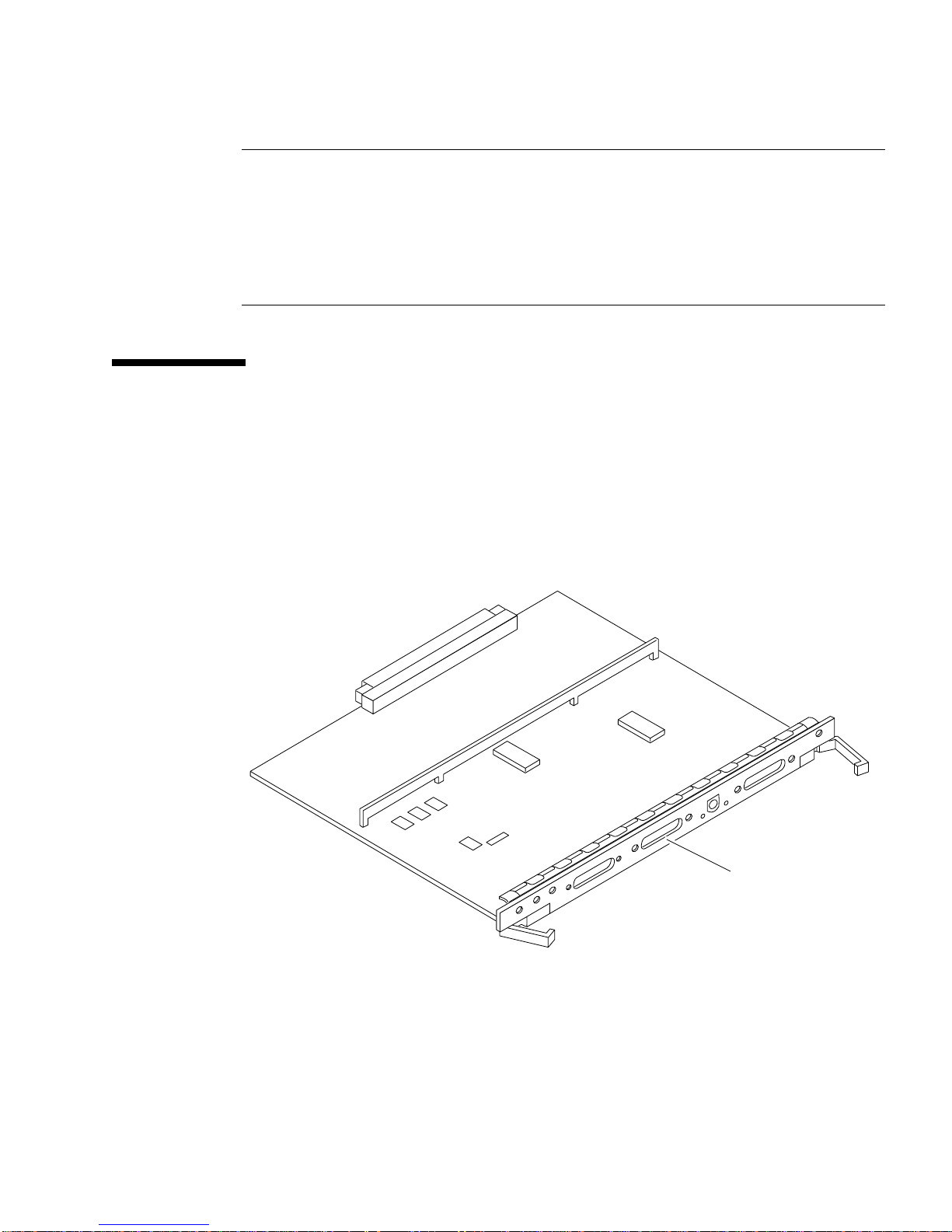
1. Connect the terminal cable into serial port A on the clock+ board (
Serial port A
FIGURE 2-9 Clock+ Board
FIGURE 2-9).
2. For Enterprise 6500/5500 systems only: route the terminal cable from the clock+
board down along the right mounting rail of the cabinet.
Use tie wraps to secure the terminal cable to the mounting rail.
Chapter 2 Cabling the System 2-9

3. Connect the terminal power cord into an AC wall outlet.
4. Configure the ASCII terminal as follows:
■ 9600 bps
■ 1 stop bit
■ 8 data bits
■ Parity off
■ Full duplex
Refer to the instruction manual shipped with the terminal for specific configuration
instructions.
Note – The setup parameters listed in Step 4 may differ from the setup at the
customer site. These parameters can be changed in the NVRAM. Refer to the s
defaults
and printenv commands in the OpenBoot Command Reference manual,
et-
part number 802-3242.
2.7 Connecting the Fiber Cable to the I/O+
Board
1. Remove the two plastic caps that cover the cable connector on the GBIC module.
2. Remove the single plastic cap covering the ends of the fiber cable.
3. Connect the fiber cable to the GBIC module installed on the I/O+ board.
Align the notch in the cable connector (
connector.
4. Connect the other end of the fiber cable to the GBIC connector on the rear panel
of the SPARCstorage™ Array (or other storage device with fiber optics interface).
Align the notch in the cable connector with the notch in the connector on the storage
device rear panel.
FIGURE 2-10) with the key notch in the module
2-10 Sun Enterprise 6500/5500/4500 Systems Installation Guide • August 2001

Fiber 0 (port A)
Fiber 1(port B)
Notch
Keyway notch
in module
connector
FIGURE 2-10 Fiber Cable and Fiber Card Connectors and Ports on the I/O+ Board
Chapter 2 Cabling the System 2-11

2.8 Connecting External SCSI Devices
External SCSI-2 devices connect to your system through the built-in single-ended
Fast/Wide SCSI-2 port on I/O+ boards (except for the board in slot 1), or through
FSBE/S, DSBE/S, SWIS/S, or DWIS/S SBus cards installed on I/O+ boards.
Note – The onboard SCSI-2 bus on the I/O+ board in slot 1 controls internal media
tray devices. Therefore, the external SCSI connector on the I/O+ board in slot 1 must
always have a terminator installed.
Note – The maximum combined length for a string of SCSI cables is 6 meters for
non-differential cables. For differential SCSI cables, the maximum is 25 meters.
When calculating the total length of a SCSI string, include external cables, internal
cables, and printed traces.
servers.
TABLE 2-2 Internal SCSI Lengths (Approximate)
Location Internal Length Comments
TABLE 2-2 lists internal measurements for the Enterprise
Enterprise 6500 slot 1 3.7 meters Includes I/O+ board traces and cables to media tray
Enterprise 5500 slot 1 3.7 meters Includes I/O+ board traces and cables to media tray
Enterprise 4500 slot 1 1.4 meters Includes I/O+ board traces and cables to media tray
SBus+ I/O board 0.43 meter Includes board traces only
Graphics+ I/O board 0.43 meter Includes board traces only
Disk board 0.64 meter Includes board traces only
For information on device addressing, priorities, and slot assignments, refer to
Appendix D, “Rules for System Configuration” in the Sun Enterprise 6500/5500/4500
Systems Reference Manual, part number 805-2632.
Caution – Do not assign the same SCSI address to two devices sharing the same
SCSI bus or SBus card. Doing so may result in equipment damage.
2-12 Sun Enterprise 6500/5500/4500 Systems Installation Guide • August 2001
To connect an external SCSI device to your system:
1. Connect a SCSI cable to the appropriate SCSI-2 host on the I/O+ board.
■ For the I/O+ board in slot 1, use an SBus card. The onboard SCSI-2 port is
reserved for the cable to the media tray.
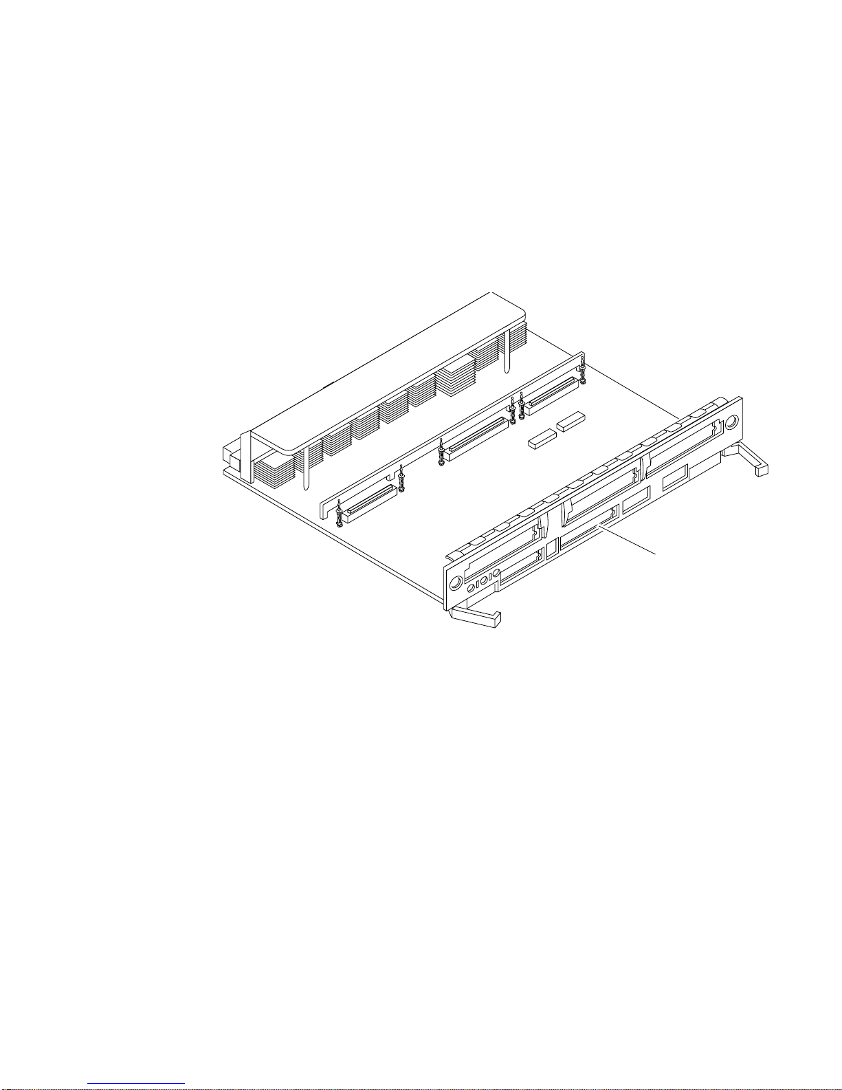
■ For I/O+ boards in slots 2 through 15, use the onboard SCSI-2 port (FIGURE 2-11)
or an SBus card.
Fast/Wide SCSI-2
FIGURE 2-11 Onboard Single-ended SCSI Connector on the I/O+ Board
2. For Enterprise 6500/5500 systems only: route the cable from the I/O+ board down
along the left mounting rail inside the cabinet.
Use tie wraps to secure the cable to the left mounting rail.
3. Connect the other end of the SCSI cable to the external SCSI-2 device.
4. For Enterprise 6500/5500 systems only: replace the rear door and kick panel.
This step concludes the hardware installation for the standalone server. You can now
power on the system and test the server.
Chapter 2 Cabling the System 2-13

2-14 Sun Enterprise 6500/5500/4500 Systems Installation Guide • August 2001

CHAPTER
3
Powering the System On and Off
This chapter contains information about powering the system on and off, reading
boot messages, and interpreting system status by viewing the LEDs.
3.1 Using JumpStart Automatic Installation
The Sun Enterprise 6500/5500/4500 systems can use the JumpStart™ automatic
installation feature that is described in installation documents for Solaris software.
The software that enables this feature is present on a hard disk in your system if the
system was built at the factory with internal disk boards or disk trays.
JumpStart will run only when the system is powered on for the first time.
Caution – JumpStart may incorrectly install the system as a standalone workstation.
You should prevent JumpStart automatic installation from proceeding if the
appropriate server-specific configuration information is not in place. Information
about the JumpStart feature is available on a card titled, “JumpStart Installation
Instructions” that is provided with the system documentation.
To prevent JumpStart installation from occurring unintentionally:
■ Do not connect the system to a network when you power it on initially.
■ Do not place a Solaris release DVD-ROM in a drive when you first power on the
machine.
Note – If JumpStart automatic installation begins unintentionally, interrupt it by
pressing L1-A (Stop-A) or Break (on TTYa). Perform a manual installation when you
are ready.
3-1

If JumpStart completes the installation incorrectly, you may need to reinstall Solaris
2.x manually.
3.2 Enterprise 6500/5500 Cabinet Systems
3.2.1 Powering On the System
Note – It is advisable to connect an ASCII terminal to the system during
installation. See Section 2.6 “Connecting an ASCII Terminal,” for terminal settings
and connections.
Observe the yellow (middle) LED on the front panel. It should go off when the boot
process completes. If it remains lit, observe the terminal screen for boot messages
produced by the firmware diagnostic program during power on.
To power on the cabinet system:
1. Begin with a safety inspection of the system:
a. Turn the system key switch to (the Standby position).
Note – The standby position ()does not turn off any AC-powered drive trays in
the lower part of the system cabinet. The key switch controls only the DC power
supply and DC-powered devices in the main cabinet.
b. Turn the AC power sequencer power switch (
The AC power sequencer is at the rear of the cabinet.
c. Verify that the cabinet AC power cord is connected to a power outlet.
FIGURE 3-2)toOff.
3-2 Sun Enterprise 6500/5500/4500 Systems Installation Guide • August 2001

On
Standby
Diagnostics
Locked
FIGURE 3-1 Key Switch on the Enterprise 6500/5500
TABLE 3-1 Key Switch Positions
Position Function
Front view
Standby
On
Diagnostics
Locked
1. Full power on self-test verbose
Off, no DC power
Normal power on
Normal power on, with full diagnostics
Normal power on, in secure mode
1
Caution – The outlet must be a 200-240 VAC 30A circuit intended solely for use by
the server cabinet. The electrical receptacles must be grounded, and the grounding
conductors serving these receptacles must be connected to the earth ground at the
service equipment.
Caution – Do not disconnect the AC power cord from the wall socket when you
work on or in the server cabinet. This connection provides a ground path that
prevents damage from electrostatic discharge.
Caution – Never move the system or expansion cabinets when system power is on.
Excessive movement can cause catastrophic disk drive failure. Always power the
system OFF before moving it.
Chapter 3 Powering the System On and Off 3-3

2. Turn on power to any expansion cabinets.
Read the documentation supplied with each type of expansion cabinet for specific
instructions.
Local/Remote switch
AC power switch
FIGURE 3-2 Switches on the AC Power Sequencer
3. Turn on power to the terminal (if applicable).
4. Set the system cabinet Local/Remote switch (
5. Turn the AC power switch (
FIGURE 3-2)toOn.
FIGURE 3-2) to Local.
Listen for the sound of AC-powered devices such as disk drives and fans in the disk
drive tray(s).
Note – The front panel keys for this switch are packed in the accessory box.
3-4 Sun Enterprise 6500/5500/4500 Systems Installation Guide • August 2001

6. Turn the key switch to the On position.
The system will run firmware diagnostics for about one minute and then boot.
You should see and hear several things happen:
■ The fans in the power supplies begin turning.
■ The left LED (green) on the front of the cabinet turns on immediately to indicate
the DC power supply is functioning.
■ The middle LED (yellow) begins flashing.
■ The right LED (green) flashes after firmware completes to denote that the
operating system is running.
■ The terminal screen lights up upon completion of the internal self-test.
7. Watch the terminal screen for any firmware error messages.
Note – If the middle front panel LED remains lit after the system has booted,
firmware has found (and deconfigured) failing hardware in the main cabinet.
POST (power-on-self-test) tests subassemblies and some interface paths between
subassemblies.
At the conclusion of testing, firmware automatically attempts to reconfigure the
system, omitting any parts of the system that have failed diagnostics.
If there are no faults, or if firmware completes a successful reconfiguration in
response to detected faults, the system boots.
If the system is unable to communicate with the network, see Section 3.4 “Failure of
Network Communications.”
Note – POST does not test drives or internal parts of SBus cards. To test these
devices, run OpenBoot PROM (OBP) diagnostics manually after the system has
booted. Refer to the OpenBoot Command Reference for instructions.
Note – If faulty parts are detected and configured out of the working system, you
and the system manager must decide whether to operate the system until
replacement parts arrive, or to halt operation. Also, if a faulty component cannot be
replaced in the field, the entire subassembly (like the system board) must be
replaced.
8. To restart firmware, or if the system hangs, press the CPU reset switch on the
clock+ board (
FIGURE 3-3).
Chapter 3 Powering the System On and Off 3-5

FIGURE 3-3 Reset Switches on the Clock+ Board
3.2.2 Reading Boot Messages
Use the boot software messages to verify that all options are installed and
recognized by the system. After firmware completes the system self-test, a message
similar to the following will appear on your screen. The message lists hardware
detected in the system.
Note – This screen display is an example only. The actual message displayed on the
screen will vary with the software running on the system.
System reset
CPU reset
16-slot Sun Enterprise 6500, Keyboard Present
OpenBoot -.- FCS, --- MB memory installed, Serial #---.
Ethernet address -:-:--:-:--:--, Host ID: ------.
If firmware indicates a hardware problem at this time, refer to the
Sun Enterprise 6500/5500/4500 Systems Reference Manual, Part 3, “Troubleshooting,”
for further instructions.
3-6 Sun Enterprise 6500/5500/4500 Systems Installation Guide • August 2001

Note – When the system finishes booting for the first time — if there is no
appropriate server configuration file on the disk drive — it may be necessary to
prevent the JumpStart automatic configuration program from running. See the
caution in Section 3.1 “Using JumpStart Automatic Installation.”
3.2.3 Interpreting Status LED Patterns
If there is no terminal on the system, basic system status information is available on
the front panel LEDs, as shown in
DC power
Fault
System running
FIGURE 3-4.
Front view
FIGURE 3-4 System Status LEDs (Cabinet Server)
TABLE 3-2 summarizes LED status indications.
TABLE 3-2 Front Panel LED Status Indicators
LED Position Condition
Left LED
(green)
Middle LED
(yellow)
Right LED
(green)
On — DC power supply is receiving AC current.
Off — There is no DC power.
On Flashing — (first 60 seconds) self-tests are running.
Off — (after self-tests end) No hardware failures.
On — (after self-tests end) Hardware failure was detected.
Off — (first 60 seconds) self-tests are running.
On Flashing — (after self-tests end) System is running.
Off — (after self-tests end) System cannot run; repair is needed.
Chapter 3 Powering the System On and Off 3-7

3.2.4 Powering Off the System
Before turning off the system power, you must halt the operating system. See the
Preface, “UNIX Commands,” to find references if you need help with the commands
for this task or other system administration procedures.
Note – Failure to halt the operating system properly can cause the loss of disk drive
data.
Note – Do not disconnect the terminal while the system is running.
Caution – To avoid damaging internal circuits, do not disconnect or connect any
cable while power is applied to the system.
To shut down the system:
1. Notify users that the system is going down.
2. Back up the system files and data to tape, if necessary.
3. Halt the system using the appropriate commands.
Refer to the Solaris Handbook for SMCC Peripherals that corresponds to your operating
system.
4. Wait for the system-halted message and the boot monitor prompt.
5. Turn the key switch on the front panel of the server to the Standby position (fully
counterclockwise).
6. Turn off the system power in this order:
1. External drives and expansion cabinets (if any)
2. System cabinet AC power switch
3. Terminal
For more system administration information on methods for shut-down and backup,
see the Preface, “UNIX Commands,” for a reference to documentation that describes
these procedures.
3-8 Sun Enterprise 6500/5500/4500 Systems Installation Guide • August 2001

3.3 Enterprise 4500 System
3.3.1 Powering On the System
Note – It is advisable to connect an ASCII terminal to the system during
installation. See Section 2.6 “Connecting an ASCII Terminal,” for terminal settings
and connections.
Observe the yellow (middle) LED on the front panel. It should go off when the boot
process completes. If it remains on, observe the terminal screen for boot messages
produced by the firmware diagnostic program during power-on.
To power on the Enterprise 4500 system:
1. Begin with a safety inspection of the system.
a. Turn the system key switch to (the Standby position).
b. Turn the AC power switch (
c. Verify that the AC power cord is connected to a power outlet.
Caution – Do not disconnect the power cord from the wall socket when working on
the server. This connection provides a ground path that prevents damage from
uncontrolled electrostatic discharge.
2. Turn on power to any expansion cabinets.
Read the documentation supplied with each type of expansion cabinet for specific
instructions.
3. Turn on the terminal (if applicable).
FIGURE 3-6)toOff.
Chapter 3 Powering the System On and Off 3-9

Standby
Front view
FIGURE 3-5 Key Switch on the Enterprise 4500
TABLE 3-3 Key Switch Positions
Position Function
On
Diagnostics
Locked
Standby
On
Diagnostics
Locked
1. Full power on self-test verbose.
Off, no DC power
Normal power on
Normal power on, with full diagnostics
Normal power on, in secure mode
1
4. Turn the AC power switch (FIGURE 3-6)toOn.
5. Turn the key switch (
FIGURE 3-5) to the On position.
You should see and hear several things happen:
■ The fans in the power supplies begin turning.
■ The top front panel LED (green) turns on immediately denoting the power
supply is delivering DC power.
■ The middle front panel LED (yellow) flashes while POST runs for
approximately 60 seconds. After 60 seconds, this LED turns off if the tests pass.
If the LED remains lighted after 60 seconds, a test has failed.
■ The bottom front panel LED (green) flashes to show that booting is successful
and the operating system is running. If this LED fails to turn on and the
middle LED is on, a severe hardware fault exists.
3-10 Sun Enterprise 6500/5500/4500 Systems Installation Guide • August 2001

Rear view
AC connector
AC power switch
FIGURE 3-6 AC Power Switch on the Enterprise 4500
Caution – Never move the system when the power is on. Doing so may result in
catastrophic disk drive failure. Always power the system off before moving it.
6. Watch the terminal screen for error messages.
POST (power-on-self-test) tests subassemblies and some interface paths between
subassemblies.
At the conclusion of testing, firmware automatically attempts to reconfigure the
system, omitting any parts of the system that have failed diagnostics.
If there are no faults, or if firmware completes a successful reconfiguration in
response to detected faults, the system boots.
Note – If faulty parts are detected and configured out of the working system, you
and the system manager must decide whether to operate the system until
replacement parts arrive, or to halt operation. Also, if a faulty component cannot be
replaced in the field, the entire subassembly (like the system board) must be
replaced.
7. To restart firmware, or if the system hangs, press the CPU reset switch (
FIGURE 3-7)
on the clock+ board.
Chapter 3 Powering the System On and Off 3-11

FIGURE 3-7 Reset Switches on the Clock+ Board
3.3.2 Reading Boot Messages
Use the boot software messages to verify that all options are installed and
recognized by the system. After firmware completes the system self-test, a message
similar to the one below will appear on your screen. The message lists hardware
detected in the system.
Note – This screen display is an example only. The actual message displayed on the
screen will depend on the software running on your system.
System reset
CPU reset
8-slot Sun Enterprise 5500/4500, Keyboard Present
OpenBoot -.- FCS, --- MB memory installed, Serial #---.
Ethernet address -:-:--:-:--:--, Host ID: ------.
If firmware indicates a hardware problem at this time, refer to the
Sun Enterprise 6500/5500/4500 Systems Reference Manual, Part 3, “Troubleshooting,”
for further instructions.
Boot the system using the procedure that is appropriate for your operating system.
See the Preface, “UNIX Commands,” for a reference to documentation that describes
this procedure.
3-12 Sun Enterprise 6500/5500/4500 Systems Installation Guide • August 2001

3.3.3 Interpreting Status LED Patterns
If there is no terminal on the system, examine the front panel LEDs (FIGURE 3-8) for
the status of the system (
Front view
FIGURE 3-8 System Status LEDs (Standalone Server)
TABLE 3-2).
DC power
Fault
System running
TABLE 3-4 Front Panel LED Status Indicators
LED Position Condition
Left LED
(green)
Middle LED
(yellow)
Right LED
(green)
On — DC power supply is receiving AC current.
Off — There is no DC power.
On Flashing — (first 60 seconds) self-tests are running.
Off — (after self-tests end) No hardware failures.
On — (after self-tests end) Hardware failure was detected.
Off — (first 60 seconds) self-tests are running.
On Flashing — (after self-tests end) System is running.
Off — (after self-tests end) System cannot run; repair is needed.
When the self-test completes, both top and bottom LEDs should be on. If the system
runs but needs service, all three LEDs will be on. If the system cannot boot, the top
and middle LEDs will be on. In a complete failure, none of the LEDs will light.
Chapter 3 Powering the System On and Off 3-13

3.3.4 Powering Off the System
Before turning off the system power, you must halt the operating system. See the
Preface, “UNIX Commands,” to find references that can help with the commands for
this task or other system administration procedures.
Note – Failure to halt the operating system properly can cause the loss of disk drive
data.
Note – Do not disconnect the terminal while the system is running.
Caution – To avoid damaging internal circuits, do not disconnect or connect in any
cable while power is applied to the system.
To shut down the system:
1. Notify users that the system is going down.
2. Back up the system files and data to tape, if necessary.
3. Halt the system using the appropriate commands.
Refer to the Solaris Handbook for SMCC Peripherals that corresponds to your operating
system.
4. Wait for the system-halted message and the boot monitor prompt.
5. Turn the key switch on the front panel of the server to the Standby position (fully
counterclockwise).
6. Turn off the system power in this order:
1. External drives and expansion cabinets (if any)
2. System AC power switch
3. Terminal
For more system administration information on methods for shut-down and backup,
see the Preface, “UNIX Commands,” for references to documentation that describes
these procedures.
3-14 Sun Enterprise 6500/5500/4500 Systems Installation Guide • August 2001

3.4 Failure of Network Communications
Description of the Problem
The system cannot communicate with a network if the system and the network hub
are not set in the same way for the Ethernet link integrity test. This problem
particularly applies to 10BASE-T network hubs, where the Ethernet link integrity
test is optional. This is not a problem for 100BASE-T networks, where the test is
enabled by default.
If you connect the system to a network and the network does not respond, use the
OpenBoot command watch-net-all to display conditions for all network
connections:
ok watch-net-all
For SBus Ethernet cards, the test can be enabled or disabled with a hardware jumper,
which you must set manually. For the TPE and MII onboard ports on the I/O+
board, the link test is enabled or disabled through software, as shown below.
Remember also that the TPE and MII ports are not independent circuits and as a
result, both ports cannot be used at the same time.
Note – Some hub designs do not use a software command to enable/disable the
test, but instead permanently enable (or disable) the test through a hardware jumper.
Refer to the hub installation or user manual for details of how the test is
implemented.
Determining the Device Names of the I/O+ Boards
To enable or disable the link test for an onboard TPE (hme) port, you must first know
the device name for the I/O+ board. To list the device names:
1. Shut down the system and take the system into OpenBoot.
2. Determine the device names of the I/O+ boards:
Chapter 3 Powering the System On and Off 3-15

a. Type:
ok show-devs
b. In the show-devs listing, find the node names.
Node names take the general form /sbus@3,0/SUNW,hme@3,8c00000.
Solution 1
Use this method while the operating system is running:
1. Become superuser.
2. Type:
# eeprom nvramrc=”probe-all install-console banner apply disable-link-pulse \
device-name “
(Repeat for any additional device names.)
# eeprom “use-nvramrc?”=true
3. Reboot the system (when convenient) to make the changes effective.
Solution 2
Use this alternate method when the system is already in OpenBoot:
1. At the monitor OpenBoot prompt, type:
ok nvedit
0: probe-all install-console banner
1: apply disable-link-pulse device-name
(Repeat this step for other device names as needed.)
(Press CONTROL-C to exit nvedit.)
ok nvstore
ok setenv use-nvramrc? true
2. Reboot to make the changes effective.
3-16 Sun Enterprise 6500/5500/4500 Systems Installation Guide • August 2001

CHAPTER
4
Software
4.1 Operating System Software and Patches
Refer to the operating system documentation that came with your system for more
information on operating system software.
4.2 Sun™ Management Center Software
Sun Management Center features a graphical user interface (GUI) that shows
various graphs reflecting system status.
Sun Management Center, intended to complement network-wide and enterprisewide system management tools, is accessible through an SNMP interface from
network tools such as Solstice SunNet Manager™.
Refer to the online Sun Management Center User’s Guide for start up and operating
instructions.
4-1

4.3 Dynamic Reconfiguration for
Hot-Pluggable System Boards
If the dynamic reconfiguration feature is enabled in the operating environment,
service providers can install, remove, or replace a hot-pluggable system board
without powering down the system. For the Solaris 2.6, Solaris 7, and Solaris 8
Operating Environments, dynamic reconfiguration applies to specific types of
boards in the Sun Enterprise 3x00. For instructions, refer to the Sun Enterprise
6x00,5x00,4x00, and 3x00 Systems Dynamic Reconfiguration User ’s Guide included in the
online AnswerBook2 for your Solaris Operating Environment or refer to the
docs.sun.com web site for more information on dynamic reconfiguration.
4.4 CPU Over-Temperature Safeguard
(COS)
The CPU over-temperature safeguard (COS) software feature is automatically
available on the Sun Enterprise server systems. COS ensures that the temperature on
any CPU/Memory+ board does not rise above the safe operating range.
Refer to the online Platform Notes for information about COS requirements and
operation.
4-2 Sun Enterprise 6500/5500/4500 Systems Installation Guide • August 2001

APPENDIX
A
Regulatory Agency Compliance
Statements
Your Sun product is marked to indicate its compliance class:
■ Federal Communications Commission (FCC)—U.S.A.
■ Department of Communications (DOC)—Canada
■ Voluntary Control Council for Interference (VCCI)—Japan
■ European Union (CE mark)—Europe
■ Bureau of Standards Metrology and Inspection (BSMI) — Taiwan
Please read the appropriate section that corresponds to the marking on your Sun
product before attempting to install the product.
A-1

A.1 FCC Class A Notice
This device complies with Part 15 of the FCC Rules. Operation is subject to the
following two conditions:
1. This device may not cause harmful interference.
2. This device must accept any interference received, including interference that
may cause undesired operation.
Note – This equipment has been tested and found to comply with the limits for a
Class A digital device, pursuant to Part 15 of the FCC Rules. These limits are
designed to provide reasonable protection against harmful interference when the
equipment is operated in a commercial environment. This equipment generates, uses
and can radiate radio frequency energy and, if not installed and used in accordance
with the instruction manual, may cause harmful interference to radio
communications. Operation of this equipment in a residential area is likely to cause
harmful interference in which case the user will be required to correct the
interference at his own expense.
Shielded Cables: Connections between the workstation and peripherals must be
made using shielded cables in order to maintain compliance with FCC radio
frequency emission limits. Networking connections can be made using unshielded
twisted-pair (UTP) cables.
Modifications: Any modifications made to this device that are not approved by Sun
Microsystems™, Inc. may void the authority granted to the user by the FCC to
operate this equipment.
A-2 Sun Enterprise 6500/5500/4500 Systems Installation Guide • August 2001

A.2 FCC Class B Notice
This device complies with Part 15 of the FCC Rules. Operation is subject to the
following two conditions:
1. This device may not cause harmful interference.
2. This device must accept any interference received, including interference that
may cause undesired operation.
Note – This equipment has been tested and found to comply with the limits for a
Class B digital device, pursuant to Part 15 of the FCC Rules. These limits are
designed to provide reasonable protection against harmful interference in a
residential installation. This equipment generates, uses and can radiate radio
frequency energy and, if not installed and used in accordance with the instructions,
may cause harmful interference to radio communications. However, there is no
guarantee that interference will not occur in a particular installation. If this
equipment does cause harmful interference to radio or television reception, which
can be determined by turning the equipment off and on, the user is encouraged to
try to correct the interference by one or more of the following measures:
■ Reorient or relocate the receiving antenna.
■ Increase the separation between the equipment and receiver.
■ Connect the equipment into an outlet on a circuit different from that to which the
receiver is connected.
■ Consult the dealer or an experienced radio/television technician for help.
Shielded Cables: Connections between the workstation and peripherals must be
made using shielded cables in order to maintain compliance with FCC radio
frequency emission limits. Networking connections can be made using unshielded
twisted pair (UTP) cables.
Modifications: Any modifications made to this device that are not approved by Sun
Microsystems, Inc. may void the authority granted to the user by the FCC to operate
this equipment.
Appendix A Regulatory Agency Compliance Statements A-3

A.3 DOC Class A Notice – Avis DOC,
Classe A
This Class A digital apparatus meets all requirements of the Canadian InterferenceCausing Equipment Regulations.
Cet appareil numérique de la classe A respecte toutes les exigences du Règlement
sur le matériel brouilleur du Canada.
A.4 DOC Class B Notice – Avis DOC,
Classe B
This Class B digital apparatus meets all requirements of the Canadian InterferenceCausing Equipment Regulations.
Cet appareil numérique de la classe B respecte toutes les exigences du Règlement sur
le matériel brouilleur du Canada.
A-4 Sun Enterprise 6500/5500/4500 Systems Installation Guide • August 2001

A.5 BSMI Class A Notice
The following statement is applicable to products shipped to Taiwan and marked as
Class A on the product compliance label.
Appendix A Regulatory Agency Compliance Statements A-5

Declaration of Conformity
Compliance ID: 1610/1601
Product Name: Sun Enterprise 6500 Family
EMC
European Union
This equipment complies with the following requirements of the EMC Directive 89/336/EEC:
EN55022:1998/CISPR22:1997 Class A
EN55024:1998 EN61000-4-2 4 kV (Direct), 8 kV (Air)
EN61000-4-3 3 V/m
EN61000-4-4 1.0 kV AC Power Lines, 0.5 kV Signal and DC Power Lines
EN61000-4-5 1 kV AC Line-Line and Outdoor Signal Lines
2 kV AC Line-Gnd, 0.5 kV DC Power Lines
EN61000-4-6 3 V
EN61000-4-8 1 A/m
EN61000-4-11 Pass
EN61000-3-2:1995 w/Amendments 1, 2 Pass
EN61000-3-3:1995 Pass
Safety
This equipment complies with the following requirements of the Low Voltage Directive 73/23/EEC:
EC Type Examination Certificates:
EN60950:1992, 2nd Edition, Amendments 1, 2, 3, 4, 11 TUV Rheinland Certificate No. S 9677038
IEC 950:1991, 2nd Edition, Amendments 1, 2, 3, 4
Evaluated to all CB Countries CB Scheme Certificate No. UL918-138989/USA
FDA DHHS Accession Number (Monitors Only)
Supplementary Information
This product was tested and complies with all the requirements for the CE Mark.
/S/ /S/
Dennis P. Symanski DATE
Manager, Compliance Engineering
Sun Microsystems, Inc.
901 San Antonio Road, MPK15-102
Palo Alto, CA 94303-4900 U.S.A
Tel: 650-786-3255
Fax: 650-786-3723
Peter Arkless DATE
Quality Manager
Sun Microsystems Scotland, Limited
Springfield, Linlithgow
West Lothian, EH49 7LR
Scotland, United Kingdom
Tel: 0506-670000
Fax: 0506-760011
A-6 Sun Enterprise 6500/5500/4500 Systems Installation Guide • August 2001

Declaration of Conformity
Compliance ID: 800/1601
Product Name: Sun Enterprise 5500 Family
EMC
European Union
This equipment complies with the following requirements of the EMC Directive 89/336/EEC:
EN55022:1998/CISPR22:1997 Class A
EN55024:1998 EN61000-4-2 4 kV (Direct), 8 kV (Air)
EN61000-4-3 3 V/m
EN61000-4-4 1.0 kV AC Power Lines, 0.5 kV Signal and DC Power Lines
EN61000-4-5 1 kV AC Line-Line and Outdoor Signal Lines
2 kV AC Line-Gnd, 0.5 kV DC Power Lines
EN61000-4-6 3 V
EN61000-4-8 1 A/m
EN61000-4-11 Pass
EN61000-3-2:1995 w/Amendments 1, 2 Pass
EN61000-3-3:1995 Pass
Safety
This equipment complies with the following requirements of the Low Voltage Directive 73/23/EEC:
EC Type Examination Certificates:
EN60950:1992, 2nd Edition, Amendments 1, 2, 3, 4, 11 TUV Rheinland Certificate No. S 9677038
IEC 950:1991, 2nd Edition, Amendments 1, 2, 3, 4
Evaluated to all CB Countries CB Scheme Certificate No. UL918-138989/USA
FDA DHHS Accession Number (Monitors Only)
Supplementary Information
This product was tested and complies with all the requirements for the CE Mark.
/S/ /S/
Dennis P. Symanski DATE
Manager, Compliance Engineering
Sun Microsystems, Inc.
901 San Antonio Road, MPK15-102
Palo Alto, CA 94303-4900 U.S.A
Tel: 650-786-3255
Fax: 650-786-3723
Peter Arkless DATE
Quality Manager
Sun Microsystems Scotland, Limited
Springfield, Linlithgow
West Lothian, EH49 7LR
Scotland, United Kingdom
Tel: 0506-670000
Fax: 0506-760011
Appendix A Regulatory Agency Compliance Statements A-7

Declaration of Conformity
Compliance ID: 800
Product Name: Sun Enterprise 4500 Family
EMC
European Union
This equipment complies with the following requirements of the EMC Directive 89/336/EEC:
EN55022:1998/CISPR22:1997 Class A
EN55024:1998 EN61000-4-2 4 kV (Direct), 8 kV (Air)
EN61000-4-3 3 V/m
EN61000-4-4 1.0 kV AC Power Lines, 0.5 kV Signal and DC Power Lines
EN61000-4-5 1 kV AC Line-Line and Outdoor Signal Lines
2 kV AC Line-Gnd, 0.5 kV DC Power Lines
EN61000-4-6 3 V
EN61000-4-8 1 A/m
EN61000-4-11 Pass
EN61000-3-2:1995 w/Amendments 1, 2 Pass
EN61000-3-3:1995 Pass
Safety
This equipment complies with the following requirements of the Low Voltage Directive 73/23/EEC:
EC Type Examination Certificates:
EN60950:1992, 2nd Edition, Amendments 1, 2, 3, 4, 11 TUV Rheinland Certificate No. S 9677038
IEC 950:1991, 2nd Edition, Amendments 1, 2, 3, 4
Evaluated to all CB Countries CB Scheme Certificate No. UL918-138989/USA
FDA DHHS Accession Number (Monitors Only)
Supplementary Information
This product was tested and complies with all the requirements for the CE Mark.
/S/ /S/
Dennis P. Symanski DATE
Manager, Compliance Engineering
Sun Microsystems, Inc.
901 San Antonio Road, MPK15-102
Palo Alto, CA 94303-4900 U.S.A
Tel: 650-786-3255
Fax: 650-786-3723
Peter Arkless DATE
Quality Manager
Sun Microsystems Scotland, Limited
Springfield, Linlithgow
West Lothian, EH49 7LR
Scotland, United Kingdom
Tel: 0506-670000
Fax: 0506-760011
A-8 Sun Enterprise 6500/5500/4500 Systems Installation Guide • August 2001

Index
A
AC switch, 2-4, 3-2, 3-9
adjust, levelling pads, 1-12
air conditioning needs, 1-6
ASCII terminal
cabling and setup, 2-9
removal, 3-8, 3-14
automatic installation, JumpStart, 3-1
B
bar, stabilizer, 1-13
boot messages, 3-6, 3-12
C
cabling
ASCII terminal, 2-9
ethernet, length, 2-8
fiber, 2-10
network, 2-5
power, 2-3
preparing for, 2-1
SCSI, 2-12
twisted-pair, 1-7
cautions
notes, warnings, xv
SCSI bus, SBus, 2-12
clearance, system, 1-10
cord, power, 1-15
D
disk drive
tray, use stabilizer bar, 1-13
drive
disk, caution
improper shutdown, 3-8
moving with power on, 3-3
test, 3-5
tray, safety, 1-13
duplicate addresses, caution, 2-12
E
error messages
POST, 3-2, 3-9
terminal, 3-2, 3-9
ethernet
cable
length, 2-8
limitations, 2-8
F
fiber cable, 2-10
floorspace, 1-9
H
halting the system, 3-8, 3-14
Index-1

I
installation, preparing for, 1-1
J
JumpStart installation program, 3-1
K
key
location in container, 1-15
switch
positions, 2-4
kick panel
replace, 2-1
L
LEDs
interpretation, 3-5
leveling
wrench, 1-13
levelling
pads, adjust, 1-12
lifting the server, 1-15
limitations, cable, ethernet, 2-8
link test function, 1-8, 2-9
local/remote switch, 3-4
M
messages
boot, 3-6, 3-12
error, 3-2, 3-9
MII connector, 1-7
P
panel
replace
kick, 2-1
rear screen, 2-1
POST
error messages, 3-2, 3-9
LED interpretation, 3-5
program, 2-9
reconfiguration of system, 3-5, 3-11
restart, 3-5
SBus card, 3-5
power
cabling, 2-3
cord, location, 1-15
off the system, 3-8, 3-14
on the system, 3-2 to 3-6
power-on self-test See POST
precaution, automatic installation JumpStart, 3-1
preparing
for cabling, 2-1
for installation, 1-1
R
rear screen
replace, 2-1
reconfiguration, system, POST, 3-11
remove
ASCII terminal, 3-8, 3-14
replace
panel
kick, 2-1
rear screen, 2-1
reset switch, 3-5
usage of, 3-11
restart, POST, 3-5
N
network
cabling, 2-5 to 2-6
site preparation, 1-7
transceiver, 1-8
notes, cautions, warnings, xv
Index-2 Sun Enterprise 6500/5500/4500 Systems Installation Guide • August 2001
S
SBus
card
POST, 3-5
test, 3-5
caution, 2-12
SCSI
bus, caution, 2-12

cabling, 2-12
server, lifting, 1-15
shipping and storing, 1-4
site preparation
air conditioning, 1-6
floorspace, 1-9
network, 1-7
stabilizer bar, 1-13
status LEDs, 3-5
switch
AC, 2-4, 3-2, 3-9
key, 3-3, 3-10
local/remote, 3-4
reset, 3-5
system clearance, 1-10
T
test
drives, 3-5
link test, 2-9
SBus cards, 3-5
tools list, 1-11, 1-15
transceiver, network, 1-8
tray, stabilizer bar, 1-13
TTY terminal, See ASCII terminal
twisted-pair cable, 1-7
U
unpacking, 1-2
W
warnings, notes, cautions, xv
wrench, leveling, 1-13
Index-3

Index-4 Sun Enterprise 6500/5500/4500 Systems Installation Guide • August 2001
 Loading...