

Page 1

Enterprise Fabric Suite 2007
User Guide
Sun Storage Fibre Channel Switch 5802
Firmware Version 7.4
Sun Microsystems, Inc.
www.sun.com
Part No. 820-4966-10
September 2008, Revision A
Submit comments about this document at: http://www.sun.com/hwdocs/feedback
Page 2

Copyright 2008 Sun Microsystems, Inc., 4150 Network Circle, Santa Clara, California 95054, U.S.A. All rights reserved.
Sun Microsystems, Inc. has intellectual property rights relating to technology that is described in this document. In particular, and without
limitation, these intellectual property rights may include one or more of the U.S. patents listed at http://www.sun.com/patents and one or
more additional patents or pending patent applications in the U.S. and in other countries.
This document and the product to which it pertains are distributed under licenses restricting their use, copying, distribution, and
decompilation. No part of the product or of this document may be reproduced in any form by any means without prior written authorization of
Sun and its licensors, if any.
Third-party software, including font technology, is copyrighted and licensed from Sun suppliers.
QLogic, Enterprise Fabric Suite, SANdoctor, and QuickTools are trademarks or registered trademarks of QLogic Corporation.
Parts of the product may be derived from Berkeley BSD systems, licensed from the University of California. UNIX is a registered trademar k in
the U.S. and in other countries, exclusively licensed through X/Open Company, Ltd.
Sun, Sun Microsystems, the Sun logo, Java, AnswerBook2, docs.sun.com, StorageTek, and Solaris are trademarks or registered trademarks of
Sun Microsystems, Inc., or its subsidiaries, in the U.S. and in other countries.
All SPARC trademarks are used under license and are trademarks or registered trademarks of SPARC International, Inc. in the U.S. and in other
countries. Products bearing SPARC trademarks are based upon an architecture developed by Sun Microsystems, Inc.
The OPEN LOOK and Sun™ Graphical User Interface was developed by Sun Microsystems, Inc. for its users and licensees. Sun acknowledges
the pioneering efforts of Xerox in researching and developing the concept of visual or graphical user interfaces for the computer industry. Sun
holds a non-exclusive license from Xerox to the Xerox Graphical User Interface, which license also covers Sun’s licensees who implement OPEN
LOOK GUIs and otherwise comply with Sun’s written license agreements.
U.S. Government Rights—Commercial use. Government users are subject to the Sun Microsystems, Inc. standard license agreement and
applicable provisions of the FAR and its supplements.
DOCUMENTATION IS PROVIDED "AS IS" AND ALL EXPRESS OR IMPLIED CONDITIONS, REPRESENTATIONS AND WARRANTIES,
INCLUDING ANY IMPLIED WARRANTY OF MERCHANTABILITY, FITNESS FOR A PARTICULAR PURPOSE OR NON-INFRINGEMENT,
ARE DISCLAIMED, EXCEPT TO THE EXTENT THAT SUCH DISCLAIMERS ARE HELD TO BE LEGALLY INVALID.
Copyright 2008 Sun Microsystems, Inc., 4150 Network Circle, Santa Clara, Californie 95054, États-Unis. Tous droits réservés.
Sun Microsystems, Inc. possède les droits de propriété intellectuels relatifs à la technologie décrite dans ce document. En particulier, et sans
limitation, ces droits de propriété intellectuels peuvent inclure un ou plusieurs des brevets américains listés sur le site
http://www.sun.com/patents, un ou les plusieurs brevets supplémentaires ainsi que les demandes de brevet en attente aux les États-Unis et
dans d’autres pays.
Ce document et le produit auquel il se rapporte sont protégés par un copyright et distribués sous licences, celles-ci en restreignent l’utilisation,
la copie, la distribution, et la décompilation. Aucune partie de ce produit ou document ne peut être reproduite sous aucune forme, par quelque
moyen que ce soit, sans l’autorisation préalable et écrite de Sun et de ses bailleurs de licence, s’il y en a.
Tout logiciel tiers, sa technologie relative aux polices de caractères, comprise, est protégé par un copyright et licencié par des fournisseurs de
Sun.
QLogic, Enterprise Fabric Suite, SANdoctor, et QuickTools sont des marques de fabrique ou des marques déposées de QLogic Corporation.
Des parties de ce produit peuvent dériver des systèmes Berkeley BSD licenciés par l’Université de Californie. UNIX est une marque déposée aux
États-Unis et dans d’autres pays, licenciée exclusivement par X/Open Company, Ltd.
Sun, Sun Microsystems, le logo Sun, Java, AnswerBook2, docs.sun.com, StorageTek, et Solaris sont des marques de fabrique ou des marques
déposées de Sun Microsystems, Inc., ou ses filiales, aux États-Unis et dans d’autres pays.
Toutes les marques SPARC sont utilisées sous licence et sont des marques de fabrique ou des marques déposées de SPARC International, Inc.
aux États-Unis et dans d’autres pays. Les produits portant les marques SPARC sont basés sur une architecture développée par Sun
Microsystems, Inc.
L’interface utilisateur graphique OPEN LOOK et Sun™ a été développée par Sun Microsystems, Inc. pour ses utilisateurs et licenciés. Sun
reconnaît les efforts de pionniers de Xerox dans la recherche et le développement du concept des interfaces utilisateur visuelles ou graphiques
pour l’industrie informatique. Sun détient une license non exclusive de Xerox sur l’interface utilisateur graphique Xerox, cette licence couvrant
également les licenciés de Sun implémentant les interfaces utilisateur graphiques OPEN LOOK et se conforment en outre aux licences écrites de
Sun.
LA DOCUMENTATION EST FOURNIE "EN L’ÉTAT" ET TOUTES AUTRES CONDITIONS, DÉCLARATIONS ET GARANTIES EXPRESSES
OU TACITES SONT FORMELLEMENT EXCLUES DANS LA LIMITE DE LA LOI APPLICABLE, Y COMPRIS NOTAMMENT TOUTE
GARANTIE IMPLICITE RELATIVE À LA QUALITÉ MARCHANDE, À L’APTITUDE À UNE UTILISATION PARTICULIÈRE OU À
L’ABSENCE DE CONTREFAÇON.
Please
Recycle
Page 3

Contents
Preface xix
1. Using Enterprise Fabric Suite 2007 1
Workstation Requirements 1
Installing Enterprise Fabric Suite 2007 2
Starting Enterprise Fabric Suite 2007 3
Exiting Enterprise Fabric Suite 2007 6
Uninstalling Enterprise Fabric Suite 2007 8
Changing the Encryption Key for the Default Fabric View File 8
Saving and Opening Fabric View Files 9
Setting Enterprise Fabric Suite 2007 Preferences 9
Using Online Help 11
Viewing Software Version and Copyright Information 12
Enterprise Fabric Suite 2007 User Interface 12
Fabric Tree 15
Graphic Window 16
Data Window and Tabs 16
Menus 17
Topology Display Menu 17
Faceplate Display Menu 18
iii
Page 4

Menu Shortcut Keys 20
Popup Menus 21
Tool Bar 22
Using the Topology Display 23
Working with Switches and Links 24
Selecting Switches and Links 24
Arranging Switches in the Topology Display 25
Topology Data Windows 25
Using the Faceplate Display 26
Alerts Panel 27
Port Views and Status 28
Working with Po rts 29
Selecting Ports 29
Faceplate Data Windows 29
2. Managing Fabrics 31
Tracking Fabric Firmware and Software Versions 31
Saving a Version Snapshot 32
Viewing and Comparing Ver si on Sn ap sh ot s 32
Exporting Version Snapshots to a File 32
Managing the Fabric Database 33
Adding a Fabric 33
Removing a Fabric 35
Opening a Fabric View File 35
Saving a Fabric View File 36
Rediscovering a Fabric 36
Deleting Switches and Links 36
Adding a New Switch to a Fabric 36
Replacing a Failed Switch 37
iv Enterprise Fabric Suite 2007 User Guide • September 2008
Page 5

Displaying Fabric Information 38
Link and Stack Link Data Windows 39
Devices Data Window 40
Displaying Fabric Status 41
Displaying the Event Browser 42
Filtering the Event Browser 44
Sorting the Event Browser 45
Saving the Event Browser to a File 46
Verifying Fibre Channel Connections 46
FC Ping Dialog 46
FC TraceRoute Dialog 47
Working with Device Information and Nicknames 49
Displaying Detailed Device Information 49
Exporting Device Information to a File 50
Managing Nicknames for Fabric Devices 50
Creating a Nickname 50
Editing a Nickname 51
Deleting a Nickname 51
Exporting Nicknames to a File 51
Importing a Nicknames File 52
Enabling Fabric Services 52
Enabling SNMP Configuration 53
Enabling In-band Management 53
3. Managing Fabric Zoning 55
Zoning Concepts 55
Zones 55
Aliases 56
Zone Sets 56
Contents v
Page 6

Zoning Database 57
Active Zoneset Data Window 58
Configured Zonesets Data Window 59
Zoning a Fabric 60
Using the Zoning Wizard 61
Managing the Zoning Database 61
Editing the Zoning Database 61
Resolving Zoning 65
Configuring the Zoning Database 65
Saving the Zoning Database to a File 67
Restoring the Zoning Database from a File 67
Restoring the Default Zoning Database 67
Removing All Zoning Definitions 68
Managing Zone Sets 68
Creating a Zone Set 68
Activating and Deactivating a Zone Set 69
Renaming a Zone Set 70
Removing a Zone Set 70
Managing Zones 70
Creating a Zone in a Zone Set 71
Copying a Zone to a Zone Set 72
Adding Zone Members 72
Renaming a Zone 73
Removing a Zone Member 73
Removing a Zone from a Zone Set 74
Removing a Zone from All Zone Sets 74
Managing Aliases 74
Creating an Alias 75
vi Enterprise Fabric Suite 2007 User Guide • September 2008
Page 7

Adding a Member to an Alias 75
Removing an Alias from All Zones 76
Merging Fabrics and Zoning 76
Zone Merge Failure 76
Zone Merge Failure Recovery 77
4. Managing Fabric Security 79
Security Consistency Checklist 79
Connection Security 80
User Account Security 80
Port Security 81
Configured Security Data Window 82
Active Security Data Window 83
Fabric Binding 84
Device Security 85
Managing Device Security 86
Using the Edit Security Dialog 87
Creating a Security Set 88
Create a Security Group Dialog 89
Creating a Security Group 89
Create a Security Group Member Dialog 90
Editing the Security Configuration on a Switch 92
Viewing Properties of a Security Set or Security Group 93
Using the Security Config Dialog 94
Archiving a Security Configuration to a File 94
Activating a Security Set 95
Deactivating a Security Set 95
Using RADIUS Servers 95
Adding a RADIUS Server 96
Contents vii
Page 8

Removing a RADIUS Server 99
Editing RADIUS Server Information 100
Modifying Authentication Order RADIUS Server Information 101
5. Managing Switches 103
Managing User Accounts 104
Creating User Accounts 105
Removing a User Account 106
Changing a User Account Password 107
Modifying a User Account 108
Displaying Switch Information 108
Switch Data Window 109
Configuring Port Threshold Alarms 116
Paging a Switch 118
Setting the Date/Time and Enabling NTP Client 119
Resetting a Switch 120
Managing Switch Stacks 121
Configuring a Switch 122
Using the Configuration Wizard 123
Switch Properties 123
Domain ID and Domain ID Lock 124
Syslog 125
Symbolic Name 125
Switch Administrative States 125
Broadcast Support 126
In-band Management 126
Fabric Device Management Interface 126
Advanced Switch Properties 127
Timeout Values 128
viii Enterprise Fabric Suite 2007 User Guide • September 2008
Page 9

Managing System Services 128
Archiving a Switch 130
Restoring a Switch 131
Testing a Switch 133
Restoring the Factory Default Configuration 135
Configuring the Network 137
Network Properties 137
Network IP Configuration 138
Network DNS Configuration 141
Network IP Security 143
Security Policies 143
Security Associations 143
Create IP Security Association Dialog 145
Create IP Security Policy Dialog 147
Configuring SNMP 149
SNMP Properties 149
SNMP Configuration 150
SNMP Trap Configuration 150
SNMP v3 Security 151
Downloading a Support File 154
Installing Feature License Keys 154
Installing Firmware 155
Using Call Home 157
Using the Call Home Profile Manager 160
Using the Call Home Profile Editor 161
Using the Call Home Profile Editor - Tech Support Center Profile Dialog
163
Applying All Profiles on a Switch to Other Switches 165
Using the Call Home Message Queue 166
Contents ix
Page 10

Testing Call Home Profiles 166
Change Over 167
6. Managing Ports 169
Displaying Port Information 169
Port Statistics Data Window 169
Port Information Data Window 173
Digital Diagnostics Monitoring 176
Monitoring Port Status 179
Displaying Port Types 179
Displaying Port Operational States 180
Displaying Port Speeds 180
Displaying Transceiver Media Status 181
Configuring Ports 181
Changing Port Symbolic Name 182
Changing Port Administrative States 183
Changing Port Speeds 183
Changing Port Types 184
I/O Stream Guard 185
Device Scan 185
Auto Performance Tuning and AL Fairness 185
Using the Extended Credits Wizard 186
Resetting a Port 188
Moving a Licensed Port 189
Testing Ports 189
Graphing Port Performance 191
Starting Performance View 192
Exiting Performance View 193
Saving and Opening Performance View Files 194
x Enterprise Fabric Suite 2007 User Guide • September 2008
Page 11

Changing the Default Performance View File Encryption Key 194
Setting Performance View Preferences 195
Setting the Polling Frequency 195
Displaying Graphs 196
Arranging Graphs in the Display 197
Customizing Graphs 197
Setting Global Graph Type 199
Rescaling a Selected Graph 199
Saving Graph Statistics to a File 200
Contents xi
Page 12

xii Enterprise Fabric Suite 2007 User Guide • September 2008
Page 13

Figures
FIGURE 1-1 Enter CD Serial Number and License Key Dialog 4
FIGURE 1-2 Password Change Required Dialog 5
FIGURE 1-3 Initial Start Dialog 5
FIGURE 1-4 Enterprise Fabric Suite 2007 Window 6
FIGURE 1-5 Save Default Fabric View File Dialog 7
FIGURE 1-6 Load Default Fabric File Dialog 7
FIGURE 1-7 Preferences Dialog – Enterprise Fabric Suite 2007 11
FIGURE 1-8 Topology Display Elements 13
FIGURE 1-9 Faceplate Display 14
FIGURE 1-10 Backplate Display 14
FIGURE 1-11 Fabric Tree 15
FIGURE 1-12 Topology Display 24
FIGURE 1-13 Faceplate Display 27
FIGURE 1-14 Alerts Panel 28
FIGURE 2-1 Fabric Version Snapshot Analysis Dialog 33
FIGURE 2-2 Add a New Fabric Dialog 34
FIGURE 2-3 Link Data Window 39
FIGURE 2-4 Devices Data Window 40
FIGURE 2-5 Events Browser 43
FIGURE 2-6 Filter Events Dialog 45
xiii
Page 14

FIGURE 2-7 FC Ping Dialog 47
FIGURE 2-8 FC TraceRoute Dialog 48
FIGURE 2-9 Detailed Devices Display Dialog 49
FIGURE 3-1 Active Zoneset Data Window 59
FIGURE 3-2 Configured Zonesets Data Window 60
FIGURE 3-3 Edit Zoning Dialog 62
FIGURE 3-4 Zoning Config Dialog 66
FIGURE 4-1 Port Binding Dialog 81
FIGURE 4-2 Configured Security Data Window 82
FIGURE 4-3 Active Security Data Window 83
FIGURE 4-4 Edit Security Dialog 87
FIGURE 4-5 Create Security Set Dialog 88
FIGURE 4-6 Create Security Group Dialog 89
FIGURE 4-7 Create a Security Group Member Dialog 90
FIGURE 4-8 Security Config Dialog 94
FIGURE 4-9 Add Server 97
FIGURE 4-10 Remove Server 99
FIGURE 4-11 Edit Radius Server Information 100
FIGURE 4-12 Modify Authentication Order - Radius Server Information 101
FIGURE 5-1 User Account Administration Dialog – Add Account 105
FIGURE 5-2 User Account Administration Dialog – Remove Account 106
FIGURE 5-3 User Account Administration Dialog – Change Password 107
FIGURE 5-4 User Account Administration Dialog – Modify Account 108
FIGURE 5-5 Switch Data Window 110
FIGURE 5-6 Switch Data Window Buttons 111
FIGURE 5-7 Port Threshold Alarm Configuration Dialog 117
FIGURE 5-8 Port Threshold Alarm Example 118
FIGURE 5-9 Switch Stacks 121
FIGURE 5-10 Switch Properties Dialog 124
FIGURE 5-11 Advanced Switch Properties Dialog 128
xiv Enterprise Fabric Suite 2007 User Guide • September 2008
Page 15

FIGURE 5-12 System Services Dialog 129
FIGURE 5-13 Restore Dialogs – Full and Selective 132
FIGURE 5-14 Switch Diagnostics Dialog 134
FIGURE 5-15 Network Properties Dialogs 138
FIGURE 5-16 IPsec Configuration Dialog 144
FIGURE 5-17 Create IP Security Association Dialog 145
FIGURE 5-18 Create IP Security Policy Dialog 147
FIGURE 5-19 SNMP Properties Dialog 149
FIGURE 5-20 SNMP v3 Manager Dialog 152
FIGURE 5-21 SNMP v3 User Editor Dialog 153
FIGURE 5-22 Features License Key Dialog 155
FIGURE 5-23 Add License Key Dialog 155
FIGURE 5-24 Load Firmware Dialog 157
FIGURE 5-25 Call Home Setup Dialog 158
FIGURE 5-26 Call Home Profile Manager Dialog 161
FIGURE 5-27 Call Home Profile Editor Dialog 162
FIGURE 5-28 Call Home Profile Editor - Tech Support Center Profile Dialog 163
FIGURE 5-29 Call Home Profile Multiple Switch Apply Dialog 165
FIGURE 5-30 Call Home Message Queue Dialog 166
FIGURE 5-31 Call Home Profile Manager Dialog 166
FIGURE 6-1 Faceplate Display — Port Statistics 170
FIGURE 6-2 Faceplate Display — Port Information 173
FIGURE 6-3 Port Information Data Window Buttons 174
FIGURE 6-4 DDM Entries and Information Button 177
FIGURE 6-5 Detailed Media Display Dialog 178
FIGURE 6-6 Port Properties Dialog 182
FIGURE 6-7 Advanced Port Properties Dialog 186
FIGURE 6-8 Designate Donor Ports 188
FIGURE 6-9 Move Port Dialog 189
FIGURE 6-10 Port Diagnostics Dialog 190
Figures xv
Page 16

FIGURE 6-11 Fabric View Graphs 192
FIGURE 6-12 Save Default Performance View File Dialog 193
FIGURE 6-13 Load Default Performance File Dialog 194
FIGURE 6-14 Preferences – Performance View 195
FIGURE 6-15 Set Graph Polling Frequency Dialog 196
FIGURE 6-16 Default Graph Options Dialog 198
xvi Enterprise Fabric Suite 2007 User Guide • September 2008
Page 17

Tables
TABLE 1-1 Workstation Requirements 2
TABLE 1-2 Topology Menu Options 17
TABLE 1-3 Faceplate Menu Options 18
TABLE 1-4 Tool Bar Buttons 22
TABLE 2-1 Devices Data Window Entries 41
TABLE 2-2 Topology Display Switch and Status Icons 42
TABLE 2-3 Severity Levels 44
TABLE 3-1 Edit Zoning Dialog Tool Bar Buttons and Icons 63
TABLE 5-1 Factory User Accounts 104
TABLE 5-2 Switch Data Window Entries 111
TABLE 5-3 Switch Resets 120
TABLE 5-4 Switch Administrative States 126
TABLE 5-5 Factory Default Configuration Settings 135
TABLE 5-6 Network Properties- IP Configuration 139
TABLE 5-7 Network Properties - DNS Configuration 141
TABLE 5-8 IPsec Configuration Dialog Buttons 144
TABLE 5-9 Create IP Security Association Dialog Fields 146
TABLE 5-10 Create IP Security Policy Dialog Fields 147
TABLE 5-11 SNMP Configuration Parameters 150
TABLE 5-12 SNMP Trap Configuration Parameters 151
xvii
Page 18

TABLE 5-13 SNMP v3 User Editor Dialog 153
TABLE 5-14 Call Home Setup Entries 158
TABLE 5-15 Call Home Editor - Tech Support Center Profile Entries 164
TABLE 6-1 Port Statistics Data Window Entries 170
TABLE 6-2 Port Information Data Window Entries 174
TABLE 6-3 Port Types 179
TABLE 6-4 Port Operational States 180
TABLE 6-5 Port Speeds 180
TABLE 6-6 Transceiver Media View 181
TABLE 6-7 Port Administrative States 183
TABLE 6-8 Port Speeds 184
TABLE 6-9 Port Types 185
xviii Enterprise Fabric Suite 2007 User Guide • September 2008
Page 19

Preface
This guide describes the Enterprise Fabric Suite™ 2007 application for Sun FC
switches and directors. This guide introduces the switch management products and
explains their installation and use. It is intended for users responsible for installing
and using switch management tools.
How This Document Is Organized
The Enterprise Fabric Suite 2007 switch management application is the primary
focus of this manual which is organized as follows:
■ Chapter 1 describes how to use Enterprise Fabric Suite 2007, its menus, and its
displays.
■ Chapter 2 describes fabric management tasks.
■ Chapter 3 describes fabric zoning management tasks.
■ Chapter 4 describes fabric security management tasks.
■ Chapter 5 describes switch management tasks.
■ Chapter 6 describes port and device management tasks.
A glossary of terms and an index are also provided.
xix
Page 20

Typographic Conventions
Typeface Meaning Examples
AaBbCc123 The names of commands, files,
and directories; on-screen
computer output
AaBbCc123 What you type, when contrasted
with on-screen computer output
AaBbCc123 Book titles, new words or terms,
words to be emphasized.
Replace command-line variables
with real names or values.
Note – Characters display differently depending on browser settings. If characters
do not display correctly, change the character encoding in your browser to Unicode
UTF-8.
Edit your.login file.
Use ls -a to list all files.
% You have mail.
%
su
Password:
Read Chapter 6 in the User’s Guide.
These are called class options.
You must be superuser to do this.
To delete a f ile, typ e rm filename.
Related Documentation
The following table lists the documentation for this product. The online
documentation is available at:
http://docs.sun.com/app/docs/prod/switch.dir#hic
Application Title Part Number Format Location
Regulatory
and safety
information
Hardware
and software
requirements
Initial switch
installation
xx Enterprise Fabric Suite 2007 User Guide • September 2008
Sun Storage Regulatory and Safety
Compliance Manual
Sun Storage Fibre Channel Switch
5802 Hardware Release Notes
Sun Storage Fibre Channel Switch
5802 Setup
820-5506-xx PDF Online
820-5539-xx PDF Online
820-4950-xx Printed
PDF
Shipping kit
Online
Page 21

Application Title Part Number Format Location
Switch
installation
Manage the
switch
Manage the
switch
Command
line interface
reference
Look up
messages and
correct
problems
Manage the
switch
Manage the
switch
Sun Storage Fibre Channel Switch
5802 Installation Guide
Sun Storage Fibre Channel Switch
5802 QuickTools User Guide
Sun Storage Fibre Channel Switch
5802 Command Line Interface Guide
Command Line Interface Quick
Reference Guide
Event Message Guide 820-4971-xx PDF Online
Simple Network Management
Protocol Reference Guide
CIM Agent Reference Guide 820-4959-xx PDF Online
820-4969-xx PDF Online
820-4972-xx PDF Online
820-4960-xx PDF Online
820-4962-xx PDF Online
820-4974-xx PDF Online
Documentation, Support, Training, and Service
Sun Function URL
Documentation http://www.sun.com/documentation/
Support http://www.sun.com/support/
Tr ai ni ng http://www.sun.com/training/
Service http://www.sun.com/service/contacting/index.xml
Sun Welcomes Your Comments
Sun is interested in improving its documentation and welcomes your comments and
suggestions. You can submit your comments by going to:
Preface xxi
Page 22

http://www.sun.com/hwdocs/feedback
Please include the title and part number of your document with your feedback:
Enterprise Fabric Suite 2007 User Guide, part number 820-4966-10.
xxii Enterprise Fabric Suite 2007 User Guide • September 2008
Page 23

CHAPTER
1
Using Enterprise Fabric Suite 2007
This section describes how to use the Enterprise Fabric Suite 2007 application and its
menus. The following topics are covered:
■ Workstation Requirements
■ Installing Enterprise Fabric Suite 2007
■ Starting Enterprise Fabric Suite 2007
■ Exiting Enterprise Fabric Suite 2007
■ Uninstalling Enterprise Fabric Suite 2007
■ Changing the Encryption Key for the Default Fabric View File
■ Saving and Opening Fabric View Files
■ Setting Enterprise Fabric Suite 2007 Preferences
■ Using Online Help
■ Viewing Software Version and Copyright Information
■ Enterprise Fabric Suite 2007 User Interface
■ Using the Topology Display
■ Using the Faceplate Display
Workstation Requirements
The requirements for fabric management workstations running Enterprise Fabric
Suite 2007 are described in
TABLE 1-1:
1
Page 24

TABLE 1-1 Workstation Requirements
Operating System • Windows 2003, XP SP1/SP2
• Solaris™ 9, 10, and 10 x86 Operating System (Solaris OS)
• Red Hat Enterprise Linux 4, 5
• SUSE Linux Enterprise Server 9, 10
Memory 512 MB or more (1GB recommended)
Disk Space 150 MB per installation
Processor 1 GHz or faster
Hardware CD-ROM drive, RJ-45 Ethernet port, RS-232 serial port (optional)
Internet Browser
(to view online help)
• Microsoft Internet Explorer 6.0 and later
• Netscape Navigator 6.0 and later
• Firefox 1.5 and later
Installing Enterprise Fabric Suite 2007
You can install Enterprise Fabric Suite 2007 on a Windows, Linux, or Solaris OS
workstation using the Enterprise Fabric Suite 2007 Installation Disk.
Note – Contact your switch distributor or authorized reseller to purchase Enterprise
Fabric Suite 2007.
To install the Enterprise Fabric Suite 2007 application, do the following:
For a Windows platform:
1. Close all programs currently running, and insert the Enterprise Fabric Suite 2007
Installation Disk into the management workstation CD-ROM drive.
2. In the upper left corner of the product introduction screen, click Management
Software.
3. Locate your platform in the table and click Install.
If the product introduction screen does not open in step 2, open the CD with
Windows Explorer and run the installation program with the following path:
data\files\Management_Software\Windows\Windows_7.04.xx.xx.exe
For a Linux platform:
Open the CD and run the installation program with the following path:
2 Enterprise Fabric Suite 2007 User Guide • September 2008
Page 25

data/files/Management_Software/Linux/Linux_7.04.xx.xx.bin
If there is no CD-ROM icon, do the following:
1. Open an xterm or other terminal window.
2. Mount the CD-ROM. From a shell prompt, enter the following:
mount /mnt/cdrom
3. Change directory to the location of the install program:
cd /mnt/cdrom/data/files/Management_Software/Linux
4. Execute the install program and follow the installation instructions.
Linux_7.04.xx.xx.bin
For a Solaris OS platform:
1. Open a terminal window. If the disk isn’t already mounted, enter the following
command:
volcheck
2. Enter following command to move to the directory on the CD that contains the
executable:
cd /cdrom/cdrom0/data/files/Management_Software/solaris
3. Execute the install program and follow the installation instructions:
Solaris_7.04.xx.xx.bin
Starting Enterprise Fabric Suite 2007
To start Enterprise Fabric Suite 2007 for the first time, do the following.
1. Start the Enterprise Fabric Suite 2007 application using one of the following
methods:
■ For Windows, double-click the Enterprise Fabric Suite 2007 shortcut, or
select Enterprise Fabric Suite 2007 from Start menu, depending on how you
installed the application. From a command line, enter the following
command:
<install_directory>\Enterprise_Fabric_Suite_2007.exe
■ For Linux or Solaris OS enter the Enterprise_Fabric_Suite_2007 command:
Chapter 1 Using Enterprise Fabric Suite 2007 3
Page 26
<install_directory>./Enterprise_Fabric_Suite_2007
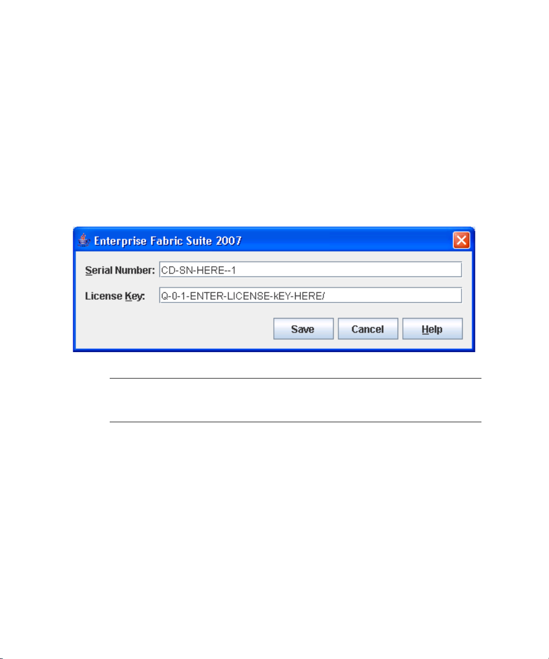
2. The serial number/license key dialog allows you to enter the serial number on the
Enterprise Fabric Suite 2007 CD ROM to activate the application, and to enter
license keys you have purchased, if any. Refer to “Installing Feature License
Keys” on page 154 for more information on license keys. Choose one of the
following:
■ If you have not purchased license keys, enter the serial number on the
Enterprise Fabric Suite 2007 CD ROM and click the Save button.
■ If you have purchased a license key(s), enter the serial number on the
Enterprise Fabric Suite 2007 CD ROM, enter the license keys, and click the
Save button.
FIGURE 1-1 Enter CD Serial Number and License Key Dialog
Note – If this is not the first session, you can update the current serial number or
license key. Open the Help menu and select License Info. On information dialog,
click the Enter Key button to openthe dialog below.
3. When Enterprise Fabric Suite 2007 first establishes a connection with a switch, for
security reasons, you will be prompted (
password initially set up by the administrator. You will be prompted to change
the default password each time you attempt to open the fabric until you change
the password. Click the OK button, and change the user account password. Refer
to “Managing User Accounts” on page 104 for more information.
4 Enterprise Fabric Suite 2007 User Guide • September 2008
FIGURE 1-2) to change your user account
Page 27
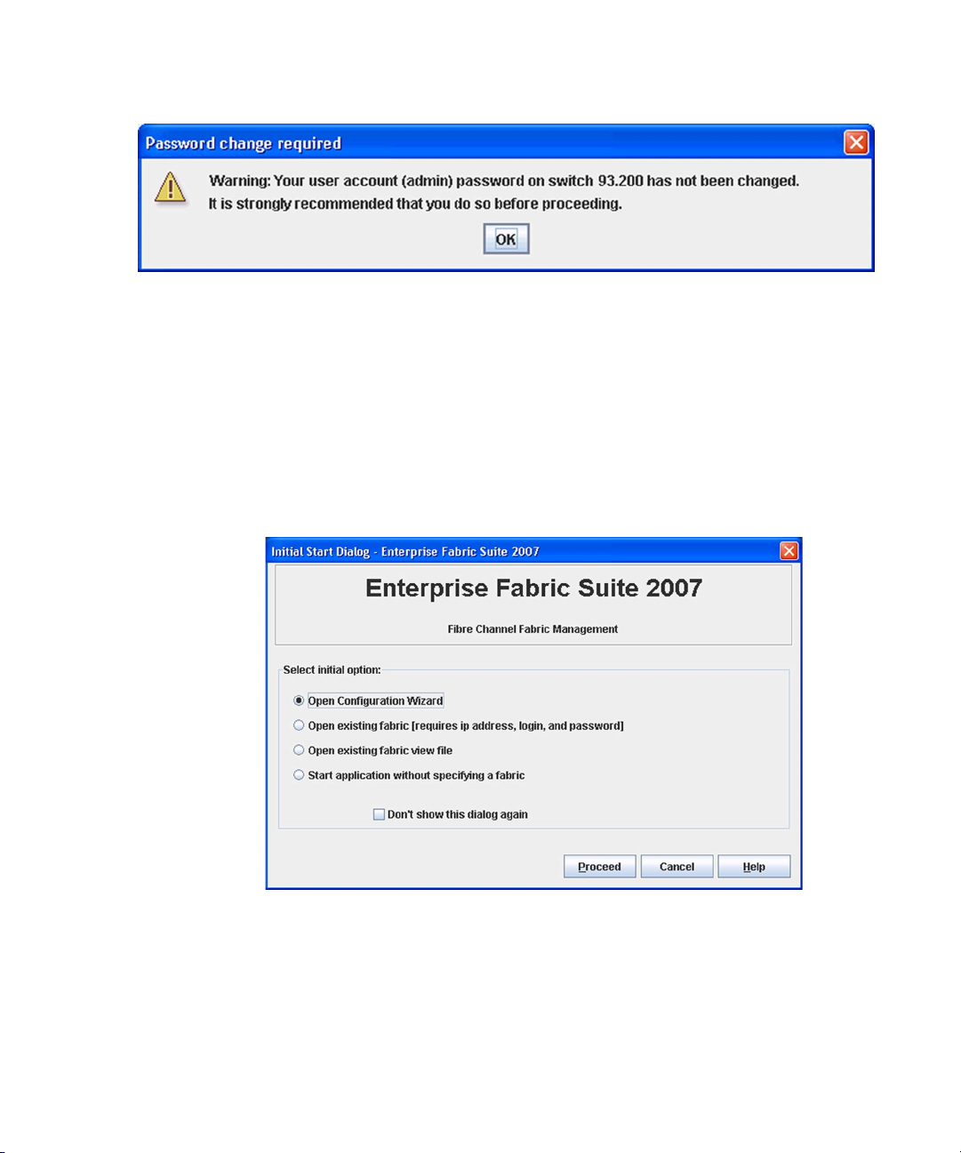
FIGURE 1-2 Password Change Required Dialog
4. If this is the first time you are managing this switch, in the Initial Start dialog,
click the Open Configuration Wizard button. When you power-up the switch, the
Configuration Wizard will recognize the switch and lead you through the
configuration process.
When starting Enterprise Fabric Suite 2007 the first time, the application opens with
the Initial Start dialog (
FIGURE 1-3). If you prefer not to see this dialog, select the
Don’t show this dialog again option. This has the same effect as disabling the
Display Initial Start Dialog preference. Refer to “Setting Enterprise Fabric Suite 2007
Preferences” on page 9 for information about setting preferences.
FIGURE 1-3 Initial Start Dialog
■ Select the Open Configuration Wizard option to open the Configuration
Wizard to configure a switch, add a new switch, replace/restore a switch, or
recover or edit an IP configuration of an existing switch.
■ Select the Open Existing Fabric option to open the Add a New Fabric dialog,
which prompts you for a fabric name, IP address, account name, and
password. Refer to “Adding a Fabric” on page 33.
Chapter 1 Using Enterprise Fabric Suite 2007 5
Page 28
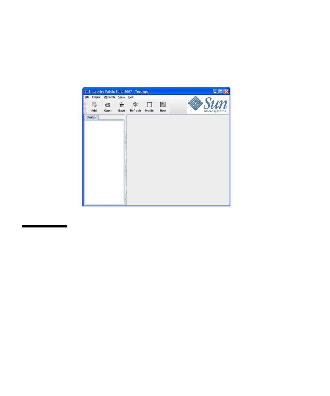
■ Select the Open Existing Fabric View File option to open the Open View dialog
which prompts you to specify a fabric view file that you saved earlier. Refer to
“Opening a Fabric View File” on page 35.
■ Select the Start Application Without Specifying a Fabric option to open the
Enterprise Fabric Suite 2007 window (FIGURE 1-4).
FIGURE 1-4 Enterprise Fabric Suite 2007 Window
Exiting Enterprise Fabric Suite 2007
To exit a Enterprise Fabric Suite 2007 application session, open the File menu and
select Exit. If you have not yet saved the default fabric view file, the Save Default
Fabric View File dialog (
the default fabric view file. Enter an encryption key in the Default Fabric File
Encryption Key field. Re-enter the encryption key in the Re-enter Encryption Key to
Confirm field. Click the OK button to save the current set of fabrics to the default
fabric view file in the working directory.
6 Enterprise Fabric Suite 2007 User Guide • September 2008
FIGURE 1-5) prompts you to save the current fabric view as
Page 29
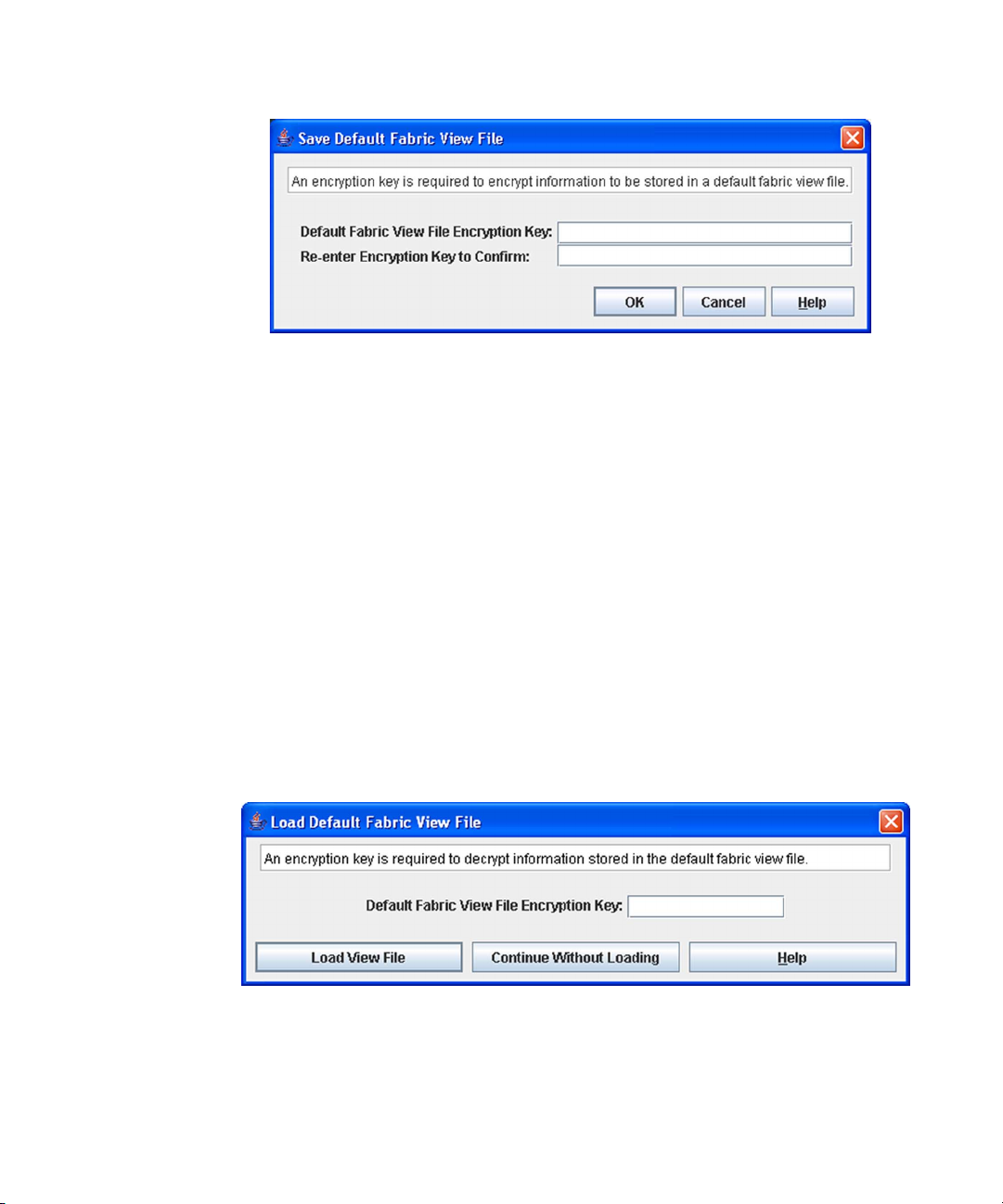
FIGURE 1-5 Save Default Fabric View File Dialog
The encryption key is used to encrypt the sensitive data in the default fabric view
file. Refer to “Changing the Encryption Key for the Default Fabric View File” on
page 8 for information about changing this encryption key. If an encryption key has
been defined and the View File Auto Save and Load preferences settings are set to
Enable, the current fabric view is automatically saved to your default fabric view file
when you close future Enterprise Fabric Suite 2007 sessions.
To prevent Enterprise Fabric Suite 2007 from prompting you to save the default
fabric view file between Enterprise Fabric Suite 2007 sessions, set the View File Auto
Save and Load preferences setting to Enable (default). Refer to “Setting Enterprise
Fabric Suite 2007 Preferences” on page 9 for more information.
In your next Enterprise Fabric Suite 2007 session, the Load Default Fabric File dialog
FIGURE 1-6) prompts you to load the default fabric view file and to specify its
(
encryption key, if there is one. In the Default Fabric File Encryption Key field, enter
the encryption key and click the Load View File button. If you do not want to load
the default fabric view file, click the Continue Without Loading button to open the
Enterprise Fabric Suite 2007 with no fabric displayed.
FIGURE 1-6 Load Default Fabric File Dialog
Chapter 1 Using Enterprise Fabric Suite 2007 7
Page 30

Uninstalling Enterprise Fabric Suite 2007
A program to uninstall Enterprise Fabric Suite 2007 was included as part of the
installation process. The UninstallerData folder in the Install directory contains the
uninstall program Uninstall_Enterprise Fabric Suite 2007. Also, a shortcut/link to
the uninstall program was installed in the installation directory during the
Enterprise Fabric Suite 2007 installation process.
The default installation directories are:
■ For Windows: C:\Program Files\Sun\Enterprise_Fabric_Suite_2007
■ For Linux: /opt/Sun/Enterprise_Fabric_Suite_2007
■ For Solaris OS: /usr/opt/Sun/Enterprise_Fabric_Suite_2007
To uninstall the Enterprise Fabric Suite 2007 application, do the following:
■ For Windows, browse for the uninstall program file or the shortcut/link that
points to the uninstall program file. The uninstall program shortcut is in the
same folder as the program shortcut (Start menu, program group, on desktop,
or user specified) that is used to start the Enterprise Fabric Suite 2007
application. Double-click the uninstall program file or shortcut/link, and
follow the instructions to uninstall the Enterprise Fabric Suite 2007 application.
■ For Linux or Solaris OS, execute the link to
Uninstall_Enterprise_Fabric_Suite_2007. If no links were created during the
installation, enter the Uninstall_Enterprise_Fabric_Suite_2007 command from
the following directory:
UninstallerData/Uninstall_Enterprise_Fabric_Suite_2007
Changing the Encryption Key for the Default Fabric View File
To change the encryption key for the Enterprise Fabric Suite 2007 default fabric view
file, do the following:
1. Open the File menu and select Save Default Fabric View File to open the Save
Default Fabric View File dialog. Enter an encryption key in the Default Fabric File
Encryption Key field.
2. Re-enter the same encryption key in the Re-enter Encryption Key to Confirm
field.
8 Enterprise Fabric Suite 2007 User Guide • September 2008
Page 31

3. Click the OK button to save the current set of fabrics to the default fabric view file
in the working directory.
Saving and Opening Fabric View Files
A fabric view file is one or more fabrics saved to a file. In addition to the Enterprise
Fabric Suite 2007 default fabric view file, you can save and open your own fabric
view files. To save a set of fabrics to a file, do the following:
1. Open the File menu and select Save View As to open the Save View dialog.
2. Enter a name for the fabric view file or click the Browse button to select an
existing file. Files are saved in the working directory.
3. Enter a password. When you attempt to open this fabric view file, you will be
prompted for this password. If you leave the File Password field blank, no
password will be required when attempting to open this fabric view file.
4. Click the OK button to save the view.
To open a fabric view file, do the following:
1. Open the File menu and select Open View File to open the Open View dialog.
2. Enter a name for the fabric view file or click the Browse button to select an
existing file.
3. If the fabric view file was saved with a password, enter the password and click
the OK button.
4. Click the OK button to open the view.
Setting Enterprise Fabric Suite 2007 Preferences
Using the Preferences dialog (FIGURE 1-7) you can:
■ Change the location of the working directory in which to save files.
■ Change the location of the browser used to view the online help.
Chapter 1 Using Enterprise Fabric Suite 2007 9
Page 32

■ Enable (default) or disable the view file auto save and load feature. Refer to
“Exiting Enterprise Fabric Suite 2007” on page 6 for more information on the
default fabric view file.
■ Enable (default) or disable the use of the Initial Start Dialog at the beginning of
an Enterprise Fabric Suite 2007 session. Refer to “Starting Enterprise Fabric
Suite 2007” on page 3 for information about the Initial Start Dialog. After a
default fabric view file is created, this setting has no effect.
■ Enable (default) or disable the Non Secure Connections Check dialog that is
displayed when you attempt to open a non secure fabric. If Display Dialog
When Making Non-secure Connections is enabled, you can open a fabric with
a non-secure fabric. Otherwise, you must have a secure connection.
■ Enable (default) or disable the Event Browser. Refer to “Displaying the Event
Browser” on page 42. If the Event Browser is enabled using the Preferences
dialog (
FIGURE 1-7), the next time Enterprise Fabric Suite 2007 is started, all
events will be displayed. If the Event Browser is disabled when Enterprise
Fabric Suite 2007 is started and later enabled, only those events from the time
the Event Browser was enabled and forward will be displayed.
■ Choose the default port view when opening the faceplate display. You can set
the faceplate to reflect the current port type (default), port speed, port
operational state, or port transceiver media. Regardless of the default port view
you choose, you can change the port view in the faceplate display by opening
the View menu and selecting a different port view option. Refer to the
corresponding subsection for more information:
■ “Displaying Port Types” on page 179
■ “Displaying Port Operational States” on page 180
■ “Displaying Port Speeds” on page 180
■ “Displaying Transceiver Media Status” on page 181
10 Enterprise Fabric Suite 2007 User Guide • September 2008
Page 33

FIGURE 1-7 Preferences Dialog – Enterprise Fabric Suite 2007
To set preferences for your Enterprise Fabric Suite 2007 sessions, do the following:
1. Open the File menu, and select Preferences to open the Preferences dialog.
2. Enter or browse for the paths to the working directory and browser.
3. In the Application-wide Options area, choose the preferences you want.
4. Click the OK button to save the changes.
Using Online Help
The browser-based online help system can be accessed from the Enterprise Fabric
Suite 2007 application several ways. Online help is also context-sensitive, that is, the
online help opens to the topic that describes the dialog you have open.
To open the first topic in the help system, choose one of the following:
■ Open the Help menu and select Help Topics
■ Click the Help button in the tool bar
■ With no dialog displayed, press the F1 function key
To open the help system to the topic that describes the dialog you have open, choose
one of the following:
■ Click the Help button in the dialog
■ Press the F1 function key
Chapter 1 Using Enterprise Fabric Suite 2007 11
Page 34

Viewing Software Version and Copyright Information
To view Enterprise Fabric Suite 2007 software version and copyright information,
open the Help menu and select About.
Enterprise Fabric Suite 2007 User Interface
The Enterprise Fabric Suite 2007 application uses the topology display (FIGURE 1-8) to
manage the fabric. The topology display shows all switches in the fabric that are able
to communicate and all connections between switches. All display types share the
basic elements including fabric tree, menu bar, tool bar, graphic window, data
window, and data window tabs.
12 Enterprise Fabric Suite 2007 User Guide • September 2008
Page 35

FIGURE 1-8 Topology Display Elements
1
2
3
4
7
5
6
Figure Legend
1 Menu Bar 5 Data Window
2 Tool Bar 6 Data Window Tabs
3 Switch/Fabric Name and Status 7 Fabric Tree
4 Graphic Window
The faceplate display (FIGURE 1-9) and backplate display (FIGURE 1-10) are used to
manage individual switches. The faceplate display shows the front of a single switch
and its ports. The backplate display shows the back of a single switch.
Chapter 1 Using Enterprise Fabric Suite 2007 13
Page 36

FIGURE 1-9 Faceplate Display
FIGURE 1-10 Backplate Display
14 Enterprise Fabric Suite 2007 User Guide • September 2008
Page 37

Fabric Tree
The fabric tree lists the managed fabrics and their switchesFIGURE 1-11. The window
width can be adjusted by clicking and dragging the moveable window border. An
fabric name entry handle located to the left of an entry in the tree indicates that the
entry can be expanded or collapsed. Click this handle or double-click the entry to
expand or collapse a fabric tree entry. A fabric entry expands to show its member
switches.
FIGURE 1-11 Fabric Tree
1
2
3
4
5
Figure Legend
1 Fabric Name Entry 4 Switch Entries
2 Fabric Name Entry Handle 5 Moveable Window Border
3 Security Lock Icon
The fabric tree provides access to the topology and faceplate displays for any fabric
or switch.
■ To open the topology display from the fabric tree, click a fabric entry.
■ To open the faceplate/backplate displays from the fabric tree, click a switch
entry.
Each fabric tree entry has a small icon next to it that uses color to indicate
operational status.
■ A green icon indicates normal operation.
Chapter 1 Using Enterprise Fabric Suite 2007 15
Page 38

■ A yellow icon indicates the switch is operational, but may require attention to
maintain maximum performance.
■ A red icon indicates a potential failure or non-operational state as when the
switch is offline.
■ A blue icon indicates that a switch is unknown, unreachable, or unmanageable.
If the status of the fabric is not normal, the fabric icon in the fabric tree will indicate
the reason for the abnormal status. The same message is provided when you rest the
mouse over the fabric icon in the fabric tree.
Note – The small lock icon next to the fabric icon in the fabric tree indicates a secure
fabric connection (SSL — Secure Socket Layer). The Security menu is available only
on a secure fabric and on the entry switch (out of band switch). Open the Switch
menu and select Services to enable the SSL option for that switch. You must then
close the fabric and re-establish a connection to secure the fabric using SSL.
Graphic Window
The graphic window (FIGURE 1-8) presents graphic information about fabrics and
switches such as the fabric topology and the switch faceplate. The window height
can be adjusted by clicking and dragging the window border that it shares with the
data window.
The faceplate display (
FIGURE 1-9) shows the front of a switch. To view the faceplate
display, open the View menu, and select View Faceplate.
The backplate display (
FIGURE 1-10) shows the back of the switch. To view the
backplate display, open the View menu, and select View Backplate.
Data Window and Tabs
The data window (FIGURE 1-8) presents a table of data and statistics associated with
the selected tab. Use the scroll bar to browse through the data. The window length
can be adjusted by clicking and dragging the border that it shares with the graphic
window.
Adjust the column width by moving the pointer over the column heading border
shared by two columns until a right/left arrow graphic is displayed. Click and drag
the arrow to the desired width.
The data window tabs present options for the type of information to display in the
data window. These options vary depending on the display.
16 Enterprise Fabric Suite 2007 User Guide • September 2008
Page 39

Menus
The Enterprise Fabric Suite 2007 menus and the tasks offered in them vary
depending on the display. For example, the Port menu and many of the Switch menu
selections are only available in the faceplate display. Refer to “Topology Display
Menu” on page 17 and “Faceplate Display Menu” on page 18 for information on the
menus.
Topology Display Menu
TABLE 1-2 lists the topology display menu options.
TABLE 1-2 Topology Menu Options
Menu Options
File Open View File
Save View As
Save Default Fabric View File
Preferences
Exit
Fabric Add Fabric
Remove Fabric
Nicknames
Fabric Tracker
Security Consistency Checklist
Rediscover Fabric
Start Performance View
FC TraceRoute (requires SANdoctor license key)
Show Event Browser
Switch Delete (available only if one switch is selected)
Export Devices
Switch Properties (available only if one switch is selected)
Network Properties (available only if one switch is selected)
SNMP Properties (available only if one switch is selected)
Stack (these options
are available only if
one stack is selected in
the graphic window)
Delete
Syslog
SNMP Properties
Set Date/Time
User Accounts
Security Consistency Checklist
Load Firmware
Edit Zoning Configuration
Chapter 1 Using Enterprise Fabric Suite 2007 17
Page 40

TABLE 1-2 Topology Menu Options (Continued)
Menu Options
View Refresh
Layout Topology
Toggle Auto Layout
Remember Layout
Wizards
Configuration Wizard
Help Help Topics
License Info
About
Faceplate Display Menu
TABLE 1-3 lists the faceplate display menu options.
TABLE 1-3 Faceplate Menu Options
Menu Options
File Open View File
Save View As
Save Default Fabric View File
Preferences
Exit
Fabric Add Fabric
Remove Fabric
Nicknames
Fabric Tracker
FC TraceRoute (requires SANdoctor license key)
Show Event Browser
18 Enterprise Fabric Suite 2007 User Guide • September 2008
Page 41

TABLE 1-3 Faceplate Menu Options (Continued)
Menu Options
Switch Archive
Restore
User Accounts
Set Date/Time
Switch Properties
Advanced Switch Properties (available only on entry switch)
Services
Call Home (Setup, Profile Manager, Message Queue, Test Profile,
Change Over)
Security Consistency Checklist
Network (Network Properties, IPv6 Ipsec Properties (available only
on secure entry switch))
SNMP (SNMP Properties, SNMP v3 Manager (available only on
secure entry switch))
Switch Diagnostics (Online Switch Diagnostics, Offline Switch
Diagnostics)
Toggle Beacons
Port Threshold Alarm Configuration
Load Firmware
Reset Switch (Hot Reset, Reset, Hard Reset)
Restore Factory Defaults
Features
Radius Servers
Download Support File
FC Ping (requires SANdoctor license key)
Stack Refresh Stack
Select All Ports
Syslog
SNMP Properties
Set Date/Time
User Accounts
Security Consistency Checklist
Reset
Load Firmware
Move Switch Up (available when a switch in stack is selected)
Move Switch Down (available when a switch in stack is selected)
Remove Switch (available when a switch in stack is selected)
Remove Links
Chapter 1 Using Enterprise Fabric Suite 2007 19
Page 42

TABLE 1-3 Faceplate Menu Options (Continued)
Menu Options
Port Port Properties
Advanced Port Properties
Reset Port
Port Binding
Port Diagnostics (requires SANdoctor license key)
Move Port
Zoning
Security Edit Security
View Refresh
Wizards
Help Help Topics
Edit Zoning
Resolve Zoning (Capture Active Zoning, Restore Configured Zoning,
Capture Merged Zoning, View Merged/Configured Differences)
Edit Zoning Config
Activate Zone Set
Deactivate Zone Set
Restore Default Zoning
Edit Security Config
Activate Security Set
Deactivate Security Set
View Port Types
View Port States
View Port Speeds
View Port Media
View Faceplate
View Backplate
Configuration Wizard
Extended Credit Wizard
Zoning Wizard
License Info
About
Menu Shortcut Keys
Shortcut key combinations, available in both the topology and faceplate displays,
provide an alternative method of accessing menu options in the application. For
example, to exit the application, press Alt+F, then press X. The shortcut key
combinations are not case-sensitive.
20 Enterprise Fabric Suite 2007 User Guide • September 2008
Page 43

Press the F1 function key to open the online help system. With no dialog displayed,
the online help system opens to the first topic. With a dialog displayed, the help
system opens to the topic describing that dialog.
Popup Menus
Popup (or shortcut) menus provide quick access to the menu options within the
current context of the application. They are displayed when you right-click on
certain areas of the topology or faceplate displays, such as inside the graphic
window of the topology display, or on a port on the faceplate display. The options
available in popup menus vary by display type (topology or faceplate) and where
you click.
Note – Additionally, mouse-over information is displayed when you rest the cursor
over key elements in the Enterprise Fabric Suite 2007 interface, such as ports, LEDs,
and fabric tree entries.
Opening the Topology Popup Menus
The topology display also offers a fabric, switch, and a link popup menu:
■ To open the fabric popup menu, right-click the graphic window background.
The fabric popup menu presents selections to refresh the fabric, select all
switches, select all links, or layout topology.
■ To open the switch popup menu, right-click the switch icon in the graphic
window. The switch popup menu presents selections to refresh the switch,
delete the switch from the display, open the Switch Properties dialog, or open
the Network Properties dialog.
■ To open the link popup menu, right-click the link. The Link popup menu
presents a selection to delete the link from the display.
Opening the Faceplate Popup Menus
To open the faceplate popup menu, right-click the faceplate image. The faceplate
popup menu presents selections to refresh the switch, select all ports, open the
Switch Properties dialog, open the Network Properties dialog, open the SNMP
Properties dialog, use the Extended Credits Wizard, open the Port Properties dialog,
run port diagnostic tests, configure RADIUS servers, open the Services dialog, and
view the Security Consistency Checklist dialog.
Chapter 1 Using Enterprise Fabric Suite 2007 21
Page 44

If no ports are selected, the port-related tasks will be unavailable in the popup
menu. Right-click a port to open the corresponding popup menu. Press the Shift or
Control key to select more than one port. If multiple ports are selected, right-click
one of the selected ports.
Tool Bar
The tool bar consists of a row of graphical buttons that you can use to access
Enterprise Fabric Suite 2007 functions. The tool bar buttons are an alternative
method to using the menu bar.
TABLE 1-4 Tool Bar Buttons
Button Description
Add Fabric — adds a new fabric to the fabric view.
Open View File — opens an existing fabric view file.
TAB LE 1- 4 describes the tool bar buttons.
Save View As — saves the current fabric view to a file.
Refresh — updates the topology or faceplate display with current
information.
Event Browser — opens the events browser.
Edit Zoning — opens the Edit Zoning dialog (available only in
faceplate/backplate displays).
22 Enterprise Fabric Suite 2007 User Guide • September 2008
Page 45

TABLE 1-4 Tool Bar Buttons (Continued)
Button Description
Edit Security — opens the Edit Security dialog (faceplate/backplate
displays on entry switch that has a secure fabric connection (SSL
enabled).
Help Topics — opens the online help file.
The Sun Microsystems logo opens a browser to the Sun Microsystems
Web site.
Using the Topology Display
The topology display (FIGURE 1-12) receives information from the selected fabric and
displays its topology. Switches and inter-switch links (ISLs) appear in the graphic
window and use color to indicate status.
■ Working w ith Switches and Links
■ Selecting Switches and Links
■ Arranging Switches in the Topology Display
■ Topology Da ta Windows
Note – Mouse-over information is displayed when you rest the cursor over key
elements in the Enterprise Fabric Suite 2007 interface, such as ports LEDs, and fabric
tree entries.
Chapter 1 Using Enterprise Fabric Suite 2007 23
Page 46

FIGURE 1-12 Topology Display
Working with Switches and Links
Switch and link icons are selectable and moveable, and serve as access points for
other displays and menus. You select switches and links to display information
about them, modify their configuration, or delete them from the display. Contextsensitive popup menus are displayed when you right-click on a switch or link icon,
or in the background of the topology display and graphic window.
Switch icon shape and color provide information about the switch and its
operational state. Lines represent links between switches. The topology display uses
green to indicate normal operation, yellow to indicate operational with errors, red to
indicate a potential failure or non-operational state, and blue to indicate unknown,
unreachable, or unmanageable. Refer to “Displaying Fabric Status” on page 41 for
more information about topology display icons.
Selecting Switches and Links
Selected ISL links in the topology display are displayed with a heavier line. Selected
switches are displayed with a light blue background. You can select switches and
links the following ways:
24 Enterprise Fabric Suite 2007 User Guide • September 2008
Page 47

■ To select one switch or link, click the switch or link.
■ To select a group of switches or links, press the Shift or Control key while
clicking each switch or link.
■ To select all switches or links, right-click anywhere in the graphic window
background, and select Select All Links or Select All Switches from the popup
menu.
■ To cancel all selections, click in the background of the graphic window.
■ To un-select one switch or link in a group of selected switches and/or links,
press the Shift or Control key while clicking the switch or link.
■ To add a switch or link to a group of selected switches and/or links, press the
Shift or Control key while clicking the switch or link.
Arranging Switches in the Topology Display
You can arrange individual switch icons in the topology display or allow Enterprise
Fabric Suite 2007 to arrange all switch icons for you:
■ To move an individual switch icon, click and drag the icon to another location
in the graphic window. Links stretch or contract to remain connected.
■ To arrange all switch icons in the topology display automatically, open the
View menu and select Layout Topology.
By default, the Toggle Auto Layout box in the View menu is selected which causes
Enterprise Fabric Suite 2007 to arrange the icons when you select Layout Topology.
You can save a custom arrangement, or layout, and restore that layout during a
Enterprise Fabric Suite 2007 session. Begin by arranging the icons, then open the
View menu and select Remember Layout. To restore the saved layout, open the View
menu, unselect the Toggle Auto Layout option, and select Layout Topology.
Topology Data Windows
The topology display provides the following data windows corresponding to the
data window tabs:
■ Devices — displays all devices logged with the name server and their
addresses within the current fabric configuration, and displays information
from the fabric and allows devices to register certain information with the
fabric. Refer to “Devices Data Window” on page 40 for more information.
■ Active Zoneset — displays the active zone set for the fabric including zones
and their member ports. Refer to “Active Zoneset Data Window” on page 58
for more information about this data window. Refer to “Zoning a Fabric” on
page 60 for information about zone sets and zones.
Chapter 1 Using Enterprise Fabric Suite 2007 25
Page 48

■ Switch — displays current network and switch configuration data for the
selected switches. Refer to “Switch Data Window” on page 109 for more
information.
■ Link — displays information about the inter-switch links. Refer to “Link and
Stack Link Data Windows” on page 39 for more information.
Using the Faceplate Display
The faceplate display (FIGURE 1-13) shows the front of a single switch, the switch
name, the switch operational state, the ports, and the port status. To open the
faceplate display when viewing the topology display, click the switch name/icon in
the fabric tree, or double-click the switch icon in the graphic window.
■ Alerts Panel
■ Port Views and Status
■ Working with Ports
■ Faceplate Data Windows
Note – Additionally, mouse-over information is displayed when you rest the cursor
over key elements in the Enterprise Fabric Suite 2007 interface, such as ports, LEDs,
and fabric tree entries.
26 Enterprise Fabric Suite 2007 User Guide • September 2008
Page 49

FIGURE 1-13 Faceplate Display
Alerts Panel
The Alerts Panel shows all reasons for status, including faults. The Alerts Panel
entries are the highlighted rows between the faceplate image and the data window
entries.
Note – The up/down arrows on the divider bar (between the Alerts Panel entries
and data windows) enable you to move the divider bar up or down. With the
faceplate image and data windows displayed, click the up arrow (on left) to move
the divider up to the top of the window, thus completely hiding the faceplate image.
Click the down arrow (on right) to move the divider back to the middle; click the
down arrow again to completely hide the data window. You can also click-and-drag
the divider bar to manually move it up or down.
Chapter 1 Using Enterprise Fabric Suite 2007 27
Page 50

FIGURE 1-14 Alerts Panel
1
2
Figure Legend
1 Aler ts Panel Entries 2 Move Divider Arrows
Port Views and Status
Port color and text provide information about the port and its operational state.
Green indicates active; gray indicates inactive. The faceplate display provides the
following views of port status corresponding to the View menu options in the
faceplate display. Refer to “Monitoring Port Status” on page 179 for more
information about these displays.
■ Port type
■ Port state
■ Port speed
■ Port media
28 Enterprise Fabric Suite 2007 User Guide • September 2008
Page 51

Working with Ports
Ports are selectable and serve as access points for other displays and menus. You
select ports to display information about them in their respective data windows or to
modify them. Context-sensitive popup menus and properties windows are accessible
through the port icons.
Selecting Ports
Selected ports in the faceplate display are outlined in light-blue.
Note – When using the Shift key to select a range of ports, the first port you click in
the range is the "anchor" selection. Subsequent ranges are based on this anchor
selection. For example, after clicking port 4 and port 9 respectively, port 4 becomes
the anchor selection. The next range includes all ports between port 4 and the next
port you select.
You can select ports the following ways.
■ To select a port, click the port.
■ To un-select a port, click outside that port.
■ To select all ports, right-click on the faceplate image and select Select All Ports
from the popup menu.
■ To select a range of consecutive ports, click a port, press the Shift key and click
another port. The application selects both end ports and all ports in between
the end ports.
■ To select several non-consecutive ports, press the Control key while clicking
each port.
■ To un-select ports in a group of selected ports, press the Control key while
clicking each port.
Faceplate Data Windows
The faceplate display provides the following data windows corresponding to the
data window tabs:
■ Devices — displays information about devices (hosts and storage targets)
connected to the switch. Refer to “Devices Data Window” on page 40 for more
information.
■ Switch — displays current switch configuration data. Refer to “Switch Data
Window” on page 109 for more information.
Chapter 1 Using Enterprise Fabric Suite 2007 29
Page 52

■ Stack Links — displays information about the links between all switches in the
stack.
■ Port Statistics — displays performance data for the selected ports. Refer to
“Port Statistics Data Window” on page 169 for more information.
■ Port Information — displays information for the selected ports. Refer to “Port
Information Data Window” on page 173 for more information.
■ Configured Zonesets — displays all zone sets, zones, and zone membership in
the zoning database. Refer to “Configured Zonesets Data Window” on page 59
for more information.
■ Configured Security — displays all security definitions currently saved in the
database. Refer to “Configured Security Data Window” on page 82 for more
information.
■ Active Security — displays the active security set. Refer to “Active Security
Data Window” on page 83 for more information.
30 Enterprise Fabric Suite 2007 User Guide • September 2008
Page 53

CHAPTER
2
Managing Fabrics
This section describes the following fabric management tasks:
■ Tracking Fabric Firmware and Software Versions
■ Managing the Fabric Database
■ Displaying Fabric Information
■ Verifying Fibre Channel Connections
■ Working w ith Dev ice Information and Nicknames
■ Enabling Fabric Services
Tracking Fabric Firmware and Software Versions
The Fabric Tracker option allows you to generate a snapshot or baseline of current
system version information, which can be viewed, analyzed and compared to other
snapshot files, and exported to a file. Information includes date and time, switch
active firmware version, device hardware, drivers, and firmware version from FDMI.
The Snapshot Analyzer option allows you to:
■ Compare two snapshots
■ Detect mismatches of firmware and driver versions
■ Detect devices that have been moved, added to or removed from the fabric.
31
Page 54

Saving a Version Snapshot
To save the current snapshot to an XML file, do the following:
1. In the faceplate display, open the Fabric menu and select Fabric Tracker, and then
select Save Snapshot.
2. Enter a filename.
3. Click the Save button to save the snapshot as an XML file.
Viewing and Comparing Version Snapshots
To view and analyze system version information, open the Fabric menu, select
Fabric Tracker, and select Analyze Snapshots. The Fabric Version Snapshot Analysis
dialog (
Click the Browse buttons to open and view the snapshot files in the corresponding
tab pages. Click the Close button to exit the Fabric Version Snapshot Analysis dialog.
The color key below the scrollable area defines the meanings of the colors used. The
Summary tab page shows a brief description of the changes that have occurred
between the older snapshot and the newer one. Use the Summary tab page to
quickly view what has changed. The Differences tab page shows a side-by-side
comparison of two snapshots.
The timestamp of each snapshot is displayed above the scroll area showing that
snapshot. The background color of the older snapshot is darker than the background
of the newer snapshot. The arrow icon between the snapshot selectors always points
from the older snapshot to the newer one. If the two snapshots have the same
timestamp, the arrow will not be displayed. The scroll bars are synchronized to view
the same portion of each snapshot file simultaneously. Click and drag the separator
bar between the two panes to resize each pane. At the top of the separator bar
between the two panes, click the left/right arrows to close the corresponding pane.
The left/right arrows move to one side.
FIGURE 2-1) opens with the Summary, Differences and Reports tab pages.
Exporting Version Snapshots to a File
The Reports tab page allows you to select one report to save to a text file. There are
two types of reports. The Summary report type shows the same format displayed on
the Summary tab page without the color highlighting. The Detail report type shows
a detailed breakdown of the differences. Use the Export button to save the selected
report to a text file.
32 Enterprise Fabric Suite 2007 User Guide • September 2008
Page 55

FIGURE 2-1 Fabric Version Snapshot Analysis Dialog
Managing the Fabric Database
A fabric database contains the set of fabrics that you have added during an
Enterprise Fabric Suite 2007 session. Initially, if you do not open an existing fabric or
fabric view file, the Enterprise Fabric Suite 2007 application opens with an empty
fabric database.
Adding a Fabric
To add a fabric to the database, do the following:
1. Open the Fabric menu and select Add Fabric to open the Add a New Fabric
dialog (
FIGURE 2-2).
Chapter 2 Managing Fabrics 33
Page 56

FIGURE 2-2 Add a New Fabric Dialog
2. Enter a fabric name in the Fabric Name field. This step is optional.
Note – Assigning a fabric name is recommended. However, if you enter a fabric
name, it must be unique.
3. In the Entry Switch field, enter the IP address or Domain Name Server (DNS)
name of the switch through which to manage the fabric. Refer to “IPv4 and IPv6
Addressing” on page 138 for more information.
4. Enter an account name and password. The factory login name and password are
"admin" and "password". The password is for the switch and is stored in the
switch firmware. Refer to “Managing User Accounts” on page 104.
5. Click the Add Fabric button.
Note – A switch supports a combined maximum of 19 logins or sessions reserved as
follows:
■ 4 logins or sessions for internal applications such as management server and
SNMP
■ 9 high priority Telnet sessions
■ 6 logins or sessions for Enterprise Fabric Suite 2007 inband and out-of-band
logins, Application Programming Interface (API) inband and out-of-band
logins, and Telnet logins. Additional logins will be refused.
34 Enterprise Fabric Suite 2007 User Guide • September 2008
Page 57

6. For security reasons, you will be prompted (FIGURE 1-2) to change your user
account password initially set up by the administrator. You will be prompted to
change the password each time you attempt to open the fabric until you change
the password. Click the OK button, and change the user account password. Refer
to “Managing User Accounts” on page 104 for more information.
Note – If the entry switch has SSL (Secure Socket Layer) enabled, the switch will
generate and display a Verify Certificate dialog that you must accept before gaining
access to the fabric. Refer to “Connection Security” on page 80 and for more
information on certificates and SSL.
Removing a Fabric
To delete a fabric from the database, do the following:
1. Select a fabric in the fabric tree.
2. Open the Fabric menu and select Remove Fabric.
Note – The Closing Sessions dialog is then displayed with the status of closing the
fabric sessions. Click the OK button to close the dialog.
Opening a Fabric View File
A fabric view file is one or more fabrics saved to a file. To open an existing view file,
do the following:
1. Open the File menu and select Open View File, or click the Open button. If the
fabric you are currently viewing has changed, you will be prompted to save the
changes to the fabric view file with the Save View dialog before opening a
different view file.
2. In the Open View dialog, enter the name of the file to open, and enter a file
password, if a password was entered when this fabric view file was saved.
3. Click the OK button.
Note – To maximize system performance and reduce the fabric event logs, limit the
number of large fabrics open at one time.
Chapter 2 Managing Fabrics 35
Page 58

Saving a Fabric View File
To save a fabric view file, do the following:
1. Open the File menu, and select Save View As.
2. In the Save View dialog, enter a new file name.
3. Enter a file password, if necessary.
4. Click the OK button.
Rediscovering a Fabric
The rediscover fabric option clears out the current fabric information being
displayed, and rediscovers all switch information. To rediscover a fabric, open the
Fabric menu, and select Rediscover Fabric. The rediscover function is more
comprehensive than the refresh function.
Deleting Switches and Links
The Enterprise Fabric Suite 2007 application does not automatically delete switches
or links that have failed or have been physically removed from the fabric Fibre
Channel network. In these cases, you can delete switches and links to bring the
display up to date. If you delete a switch or a link that is still active, the Enterprise
Fabric Suite 2007 application will restore it automatically. You can also refresh the
display. To delete a switch from the topology display, do the following:
1. Select a switch in the topology display.
2. Open the Switch menu and select Delete.
To delete a link, do the following:
1. Select a link in the topology display.
2. Right-click the link and select Delete from the popup menu.
Adding a New Switch to a Fabric
If there are no special conditions to be configured for the new switch, simply plug in
the switch and the switch becomes functional with the default fabric configuration.
The default fabric configuration settings are:
36 Enterprise Fabric Suite 2007 User Guide • September 2008
Page 59

■ Fabric zoning is sent to the switch from the fabric.
■ All ports will be GL_Ports.
■ The default IP address 10.0.0.1 is assigned to the switch without a gateway or
boot protocol configured (RA R P, BO O TP, a n d D H C P) .
If you are adding a switch to a fabric and do not want to accept the default fabric
configuration, do the following:
1. If the switch is not new from the factory, reset the switch to the factory
configuration before adding the switch to the fabric by selecting Restore Factory
Defaults in the Switch menu from the faceplate display.
2. If you want to manage the switch through the Ethernet port, you must first
configure the IP address using the Network Properties dialog or the
Configuration Wizard.
3. Configure any special switch settings. To open the Zoning Config dialog, open
the Zoning menu, and select Edit Zoning Config.
4. Plug in the inter-switch links (ISL), but do not connect the devices.
5. Configure the port types for the new switch using the Port Properties dialog. The
ports can be G_Port, GL_Port, F_Port, FL_Port, or Donor.
6. Connect the devices to the switch.
7. Make any necessary zoning changes using the Edit Zoning dialog. To open the
Edit Zoning dialog, open the Zoning menu, and select Edit Zoning. To open the
Zoning Config dialog, open the Zoning menu, and select Edit Zoning Config.
Replacing a Failed Switch
The archive/restore works for all switches. However, the Restore menu item is not
available for the in-band switches. You can only restore a switch out-of-band (the
fabric management switch). Enterprise Fabric Suite 2007 will archive and restore
only the settings that can be configured with Enterprise Fabric Suite 2007. Refer to
“Archiving a Switch” on page 130 and “Restoring a Switch” on page 131 for
information about archive and restore. Use the following procedure to replace a
failed switch for which an archive is available.
1. At the failed switch:
a. Turn off the power and disconnect the AC power cords.
b. Note port locations and remove the interconnection cables and SFPs.
c. Remove the failed switch.
Chapter 2 Managing Fabrics 37
Page 60

2. At the replacement switch:
a. Mount the switch in the location where the failed switch was removed.
b. Install the SFPs using the same ports as were used on the failed switch.
Caution – Do not reconnect inter-switch links, target devices, and initiator devices
at this time. Doing so could invalidate the fabric zoning configuration.
c. Attach the AC power cords and power up the switch.
3. Select the failed switch in the topology display. Open the Switch menu and select
Delete.
4. Restore the configuration from the failed switch to the replacement switch:
a. Open a new fabric to the replacement switch.
b. Open the faceplate display for the replacement switch. Open the Switch menu
and select Restore.
c. In the Restore dialog, enter the archive file from the failed switch or browse for
the file.
d. Click the Restore button.
5. Reset the replacement switch to activate the configuration formerly possessed by
the failed switch including the domain ID and the zoning database. Open the
Switch menu and select Reset Switch.
6. Reconnect the inter-switch links, target devices, and initiator devices to the
replacement switch using the same ports as were used on the failed switch.
Displaying Fabric Information
The topology display is your primary tool for monitoring a fabric. The graphic
window of the topology display provides status information for switches, interswitch links, and the Ethernet connection to the management workstation. Refer to
Link data window (
The topology display data windows show device, active zone set, switch, and link
information.
38 Enterprise Fabric Suite 2007 User Guide • September 2008
FIGURE 2-3) for more information.
Page 61

Refer to “Devices Data Window” on page 40 for information on devices in a fabric.
Refer to “Active Zoneset Data Window” on page 58 for information on zone
definitions for the active zone set. Refer to “Switch Data Window” on page 109 for
information about the Name Server and Switch data windows. Refer to “Link and
Stack Link Data Windows” on page 39 for information on switch links.
Link and Stack Link Data Windows
The Link data window (FIGURE 2-3) displays information about all switch links in the
fabric or selected links in the topology display. This information includes the switch
name, the port number at the end of each link, and the link status icon. To open the
Link data window, click the Link tab below the data window in the topology
display.
The Stack Links data window displays information about all switch links for a stack
of switches in the faceplate display. This information includes the switch names, the
port number at the end of each link, and the link status icon. To open the Stack Links
data window, click a stack icon in the fabric tree, and click the Stack Links tab below
the data window in the stack faceplate display.
FIGURE 2-3 Link Data Window
Chapter 2 Managing Fabrics 39
Page 62

Devices Data Window
The Devices data window (FIGURE 2-4) displays information about the devices that
are logged into the fabric. Click the Devices tab below the data window to display
device information for all devices that are logged into the selected fabric. To narrow
the display to devices that are logged into specific switches, select one or more
switches in the fabric tree or the topology display. Refer to “Exporting Device
Information to a File” on page 50 for exporting device information.
FIGURE 2-4 Devices Data Window
TABLE 2-1 describes the entries in the Devices data window.
40 Enterprise Fabric Suite 2007 User Guide • September 2008
Page 63

TABLE 2-1 Devices Data Window Entries
Entry Description
Port WWN Port world wide name
Nickname Device port nickname. To create a new nickname or edit an
existing nickname, double-click the cell and enter a nickname in
the Edit Nickname dialog. Refer to “Managing Nicknames for
Fabric Devices” on page 50 for more information.
Details Click the (i) to display additional information about the device.
Refer to “Displaying Detailed Device Information” on page 49.
FC Address Fibre Channel address
Switch Switch name
Port Switch port number
Target/Initiator Device type: Target, Initiator, or Both
Vendor Host Bus Adapter/Device Vendor
Active Zones The active zone to which the device belongs
Row # Row number reference for each listing in the Devices data
window table
Displaying Fabric Status
The fabric updates the topology and faceplate displays by forwarding changes in
status to the management workstation as they occur. You can allow the fabric to
update the display status, or you can refresh the display at any time. To refresh the
topology display, do one of the following:
■ Click the Refresh button.
■ Open the View menu and select Refresh.
■ Press the F5 key.
■ Right-click anywhere in the background of the topology display and select
Refresh Fabric from the popup menu.
The topology display uses switch and status icons to provide status information
about switches, inter-switch links, and the Ethernet connection. The switch status
icons, displayed on the left side of a switch, vary in shape and color. Switches
controlled by an Ethernet Internet Protocol have a colored Ethernet icon displayed
on the right side of the switch. A green Ethernet icon indicates normal operation,
yellow indicates a condition that may require attention to maintain maximum
performance, and red indicates a potential failure.
TABLE 2-2 shows the different
switch icons and their meanings.
Chapter 2 Managing Fabrics 41
Page 64

Note – Enterprise Fabric Suite 2007 may not support all firmware versions. If the
version of Enterprise Fabric Suite 2007 was not intended to support the firmware
version on the switch, a warning status of “FW/GUI mismatch” is displayed for the
switch. A switch with this status will still be manageable, but may preclude some
operations from being performed.
TABLE 2-2 Topology Display Switch and Status Icons
Switch Icon Description
Switch status icons
• Normal operation (green)
• Warning–operational with errors (yellow)
• Critical–potential failure (red)
• Unknown–communication status unknown, unreachable,
or unmanageable (blue)
Fabric management switch Ethernet icons
• Ethernet connection normal (green)
• Ethernet connection warning (yellow)
• Ethernet connection critical (red)
Switch is not manageable with this version of Enterprise
Fabric Suite 2007. Use the management application that was
shipped with this switch.
Displaying the Event Browser
The Event Browser (FIGURE 2-5) displays a list of events generated by the switches in
the fabric and the Enterprise Fabric Suite 2007 application. Events that are generated
by the Enterprise Fabric Suite 2007 application are not saved on the switch, but can
be saved to a file during the Enterprise Fabric Suite 2007 session.
Entries in the Event Browser are formatted by severity, time stamp, source, type, and
description. The maximum number of entries allowed in the Event Browser is 10,000.
The maximum number of entries allowed on a switch is 1200. Once the maximum is
reached, the event list wraps and the oldest events are discarded and replaced with
the new events. Event entries from the switch, use the switch time stamp, while
event entries generated by the application have a workstation time stamp. You can
filter, sort, and export the contents of the Event Browser to a file. The Event Browser
begins recording when enabled and Enterprise Fabric Suite 2007 is running.
42 Enterprise Fabric Suite 2007 User Guide • September 2008
Page 65

If the Event Browser is enabled using the Preferences dialog, the next time
Enterprise Fabric Suite 2007 is started all events from the switch log will be
displayed. If the Event Browser is disabled when Enterprise Fabric Suite 2007 is
started and later enabled, only those events from the time the Event Browser was
enabled and forward will be displayed.
To display the Event Browser, open the Fabric menu and select Show Event Browser,
or click the Events button on the tool bar. If the Show Event Browser selection or the
Events button is grayed-out, you must first enable the Events Browser setting in the
Preferences dialog. Refer to “Setting Enterprise Fabric Suite 2007 Preferences” on
page 9.
FIGURE 2-5 Events Browser
1
2
Figure Legend
1 Column Sorting Buttons 2 Severity Columns
Severity is indicated in the severity column using icons as described in TABLE 2-3.
Chapter 2 Managing Fabrics 43
Page 66

TABLE 2-3 Severity Levels
Severity Icon Description
Alarm — a "serviceable event". This means that attention by the user or
field service is required. Alarms are posted asynchronously to the screen
and cannot be turned off. If the alarm denotes that a system error has
occurred the customer and/or field representative will generally be directed
to provide a "show support" capture of the switch.
Critical event — an event that indicates a potential failure. Critical log
messages are events that warrant notice by the user. By default, these log
messages will be posted to the screen. Critical log messages do not have
alarm status as they require no immediate attention from a user or service
representative.
Warning event — an event that indicates errors or other conditions that may
require attention to maintain maximum performance. Warning messages
will not be posted to the screen unless the log is configured to do so.
Warning messages are not disruptive and, therefore, do not meet the criteria
of Critical. The user need not be informed asynchronously
No icon Informative — an unclassified event that provides supporting information.
Note – Events (Alarms, Critical, Warning, and Informative) generated by the
application are not saved on the switch. They are permanently discarded when you
close a Enterprise Fabric Suite 2007 session, but you can save these events to a file on
the workstation before you close Enterprise Fabric Suite 2007 and read it later with a
text editor or browser.
Note – Events generated by the switch are stored on the switch, and will be
retrieved when the application is restarted. Some alarms are configurable. Refer to
“Configuring Port Threshold Alarms” on page 116.
Filtering the Event Browser
Filtering the Event Browser allows you to display only those events that are of
interest based on the event severity, timestamp, source, type, and description. To
filter the Event Browser, open the Filter menu and select Filter Entries. This opens
the Filter Events dialog (
meet all of the criteria in the Filter Events dialog. If the filtering criteria is cleared or
changed, then all the events that were previously hidden that satisfy the new criteria
will be shown.
44 Enterprise Fabric Suite 2007 User Guide • September 2008
FIGURE 2-6). The Event Browser displays those events that
Page 67

You can filter the event browser in the following ways:
■ Severity — select one or more of the corresponding options to display alarm
events, critical events, warning events, or informative events.
■ Date/Time — select one or both of the From: and To: options. Enter the
bounding timestamps (MM/DD/YY HH:MM AA) to display only those events
that fall within those times. ("AA" indicates AM or PM.) The current year (YY)
can be entered as either 2 or 4 digits. For example, 12/12/07 will be interpreted
December 12, 2007.
■ Text — select one or more of the corresponding options and enter a text string
(case sensitive) for event source, type, and description. The Event Browser
displays only those events that satisfy all of the search specifications for the
Source, Type, and Description text.
FIGURE 2-6 Filter Events Dialog
Sorting the Event Browser
Sorting the Event Browser allows you to display the events in alphanumeric order
based on the event severity, timestamp, source, type, or description. Initially, the
Event Browser is sorted in ascending order by timestamp. To sort the Event
Browser, click the Severity, Timestamp, Source, Type, or Description column
Chapter 2 Managing Fabrics 45
Page 68

headings. You can also open the Sort menu and select By Severity, By Timestamp,
By Source, By Type, or By Description. Successive sort operations of the same type
alternate between ascending and descending order
Note – We recommend using unique fabric names and switch symbolic names to
better identify event log entries by source.
Saving the Event Browser to a File
You can save the displayed Event Browser entries to a file. Filtering affects the save
operation, because only displayed events are saved. To save the Event Browser to a
file, do the following:
1. Filter and sort the Event Browser to obtain the desired display.
2. Open the File menu and select Save As.
3. Select a folder and enter a file name in which to save the event log and click the
Save button. The file can be saved in XML, CSV, or text format. XML files can be
opened with an internet browser or text editor. CSV files can be opened with
most spreadsheet applications.
Verifying Fibre Channel Connections
Testing and tracing FC connections consists of utilizing the FC Ping and FC
TraceRoute dialogs to time and track frames from specified targets and destinations.
FC Ping Dialog
The FC Ping dialog (FIGURE 2-7) allows you to send an ECHO frame to a specified
target and verify the frame was returned.
Note – The SANdoctor™ license key for Sun Storage Fibre Channel Switch 5802 is
required to enable this feature. Contact your switch distributor or authorized reseller
for information on purchasing the SANdoctor license key.
46 Enterprise Fabric Suite 2007 User Guide • September 2008
Page 69

FIGURE 2-7 FC Ping Dialog
To verify a Fibre Channel connection, do the following:
1. Open the Switch menu and select FC Ping to open the FC Ping dialog.
2. Open the Destination drop-down list and select a destination port.
3. Select the Port WWN or Port Address option.
4. In the Repeat area, use the arrow keys to select or type in a value (between 1-100)
for the number of FC ping attempts to perform.
5. In the Timeout area, select the number of seconds to continue attempting the FC
ping operation before timing out. Click and drag the slide bar to move the slide
bar.
6. Click the Ping button, and view the results in the text window.
FC TraceRoute Dialog
The FC TraceRoute dialog (FIGURE 2-8) allows you to map the route trip a frame takes
from source to destination and back.
Chapter 2 Managing Fabrics 47
Page 70

Note – The SANdoctor license key is required to enable this feature. The FC
TraceRoute option is displayed in the Fabric menu on all switches in a fabric if at
least one switch in the fabric has a SANdoctor license. However, the FC TraceRoute
option is only functional on switches that have the SANdoctor license. Contact your
switch distributor or authorized reseller for information on purchasing the
SANdoctor license key.
FIGURE 2-8 FC TraceRoute Dialog
To trace a Fibre Channel connection, do the following:
1. Open the Fabric menu and select FC TraceRoute to open the FC TraceRoute
dialog.
2. Open the Source drop-down list and select a source port.
3. Select the Port WWN or Port Address option.
4. Open the Destination drop-down list and select a destination port.
5. Select the Port WWN or Port Address option.
6. In the Maximum Round-trip Hops list, use the arrow keys to select or type in a
value (between 1-32).
7. Click the Trace button, and view the results in the text window.
48 Enterprise Fabric Suite 2007 User Guide • September 2008
Page 71

Working with Device Information and Nicknames
Enterprise Fabric Suite 2007 provides for the following:
■ Displaying Detailed Device Information
■ Exporting Device Information to a File
■ Managing Nicknames for Fabric Devices
Displaying Detailed Device Information
In addition to the information that is available in the Devices data window, you can
click the (i) in the Details column to display more information in the Detailed Device
Display dialog (
Note – The Detailed Device Display dialog shows detailed information for HBAs
configured for FDMI. If the HBA is not configured for FDMI, supplemental and
vendor information in the Detailed Device Display dialog is listed as "Undefined" or
"Data Unavailable". Contact your HBA representative for more information on
configuring your HBA for FDMI.
FIGURE 2-9).
FIGURE 2-9 Detailed Devices Display Dialog
Chapter 2 Managing Fabrics 49
Page 72

Exporting Device Information to a File
To save device information to a file, open the topology display and do the following:
1. Select one or more switches in the graphic window. If no switches are selected,
Devices information is gathered for all switches.
2. Open the Switch menu and select Export Devices.
3. In the Save dialog, enter a file name. Select the extension for the type of output
file (CSV or text format) to be saved. CSV files can be opened with Microsoft
Excel or most spreadsheet applications.
4. Click the Save button.
Managing Nicknames for Fabric Devices
A nickname is a user-definable, meaningful name that can be used in place of the
world wide name. You can assign a nickname to a world wide name of a device.
Assigning a nickname makes it easier to recognize device ports when zoning your
fabric or when viewing the Devices data window. You can add, edit, delete, import
and export nicknames using the Nicknames dialog. A nickname must start with a
letter and can have up to 64 characters. Valid characters include alphanumeric
characters [aA-zZ][0-9] and special symbols [$ _ - ^ ].
Note – Nicknames are stored on switches with firmware 6.6 and later. However,
with 5.x firmware, nicknames are stored in an XML file on the workstation. To use
nicknames stored on a workstation with 5.x firmware, you must import the 5.x
nicknames XML file and save the changes. The maximum number of nicknames
allowed is 5000.
Creating a Nickname
To create a device port nickname, do the following:
1. Open the Fabric menu and select Nicknames to open the Nicknames dialog. The
device entries are listed in table format.
2. Choose one of the following methods to enter a nickname:
■ Double-click a cell in the Nicknames column, and enter a new nickname in
the text field. Click the Apply button to save the changes and open the Save
Nicknames dialog.
50 Enterprise Fabric Suite 2007 User Guide • September 2008
Page 73

■ Click on a device in the table. Open the Edit menu and select Create
Nickname to open the Add Nickname dialog. In the Add Nickname dialog,
enter a nickname and WWN and click the OK button.
Editing a Nickname
A nickname must start with a letter and can have up to 64 characters. Valid
characters include alphanumeric characters [aA-zZ][0-9] and special symbols [$ _ ^].
In the topology or faceplate display, open the Fabric menu and select Nicknames to
open the Nicknames dialog. The device entries are listed in table format. Choose one
of the following methods to edit a nickname:
■ Double-click a cell in the Nicknames column, and edit the nickname in the text
field. In the Nicknames dialog, click the Apply button to open the Save
Nicknames dialog.
■ Click on a device entry in the table. Open the Edit menu and select Edit
Nickname to open the Edit Nicknames dialog. Edit the nickname in the text
field, and click the OK button. In the Nicknames dialog, click the Apply button
to save the changes.
Deleting a Nickname
To delete a device port nickname, do the following:
1. Open the Fabric menu and select Nicknames to open the Nicknames dialog.
2. Choose one of the following:
■ Click a device in the table. Open the Edit menu and select Delete Nickname.
■ Double-click a cell in the Nicknames column, and delete the nickname text.
3. Click the Apply button to open the Save Nicknames dialog.
Exporting Nicknames to a File
You can save nicknames to a file. This is useful for retaining nicknames of devices
moved to another fabric. To save nicknames to an XML file, do the following:
1. Open the Fabric menu and select Nicknames to open the Nicknames dialog.
2. Open the File menu in the Nicknames dialog, and select Export.
3. Enter a name for the XML nickname file in the Save dialog and click Save.
Chapter 2 Managing Fabrics 51
Page 74

Importing a Nicknames File
Importing a nicknames file merges (adds) the contents to the existing nicknames file
used by Enterprise Fabric Suite 2007. This is useful for when retaining nicknames for
devices moved to another fabric. To import a nickname file, do the following:
1. Open the Fabric menu and select Nicknames to open the Nicknames dialog.
2. Open the File menu in the Nicknames dialog, and select Import.
3. Select a nickname file in the Open dialog and click Open. When prompted to
overwrite existing nicknames, click Yes.
4. Click the Apply button to open the Save Nicknames dialog.
5. Click the Save button to save the nicknames file to the switches in the fabric.
Enabling Fabric Services
Fabric services includes SNMP and in-band management. Simple Network
Management Protocol (SNMP) is the protocol governing network management and
monitoring of network devices. SNMP security consists of a read community string
and a write community string, that are basically the passwords that control read and
write access to the switch. The read community string ("public") and write
community string ("private") are set at the factory to these well-known defaults and
should be changed if SNMP is enabled using the System Services or SNMP
Properties dialogs. If SNMP is enabled (default) and the read and write community
strings have not been changed from their defaults, you risk unwanted access to the
switch. Refer to “Enabling SNMP Configuration” on page 53 for more information.
SNMP is enabled by default.
In-band management is the ability to manage switches across inter-switch links
using Enterprise Fabric Suite 2007, SNMP, management server, or the application
programming interface. The switch comes from the factory with in-band
management enabled. If you disable in-band management on a particular switch,
you can no longer communicate with that switch by means other than a direct
Ethernet or serial connection. Refer to “Enabling In-band Management” on page 53
for more information.
52 Enterprise Fabric Suite 2007 User Guide • September 2008
Page 75

Enabling SNMP Configuration
To enable SNMP configuration, do the following:
1. Choose one of the following:
■ On the faceplate display, open the Switch menu and select SNMP Properties to
open the SNMP Properties dialog. In the SNMP Configuration area, select the
SNMP Enabled option.
■ On the faceplate display, open the Switch menu and select Services to open the
System Services dialog. Select the SNMP option.
2. Click the OK button to save the change.
Enabling In-band Management
To enable In-band Management, do the following:
1. On the faceplate display, open the Switch menu and select Switch Properties to
open the Switch Properties dialog.
2. Select the In-band Management Enable option.
3. Click the OK button to save the change to the switch.
Chapter 2 Managing Fabrics 53
Page 76

54 Enterprise Fabric Suite 2007 User Guide • September 2008
Page 77

CHAPTER
3
Managing Fabric Zoning
This section consists of zoning concepts and tasks.
Zoning Concepts
The following zoning concepts provide some context for the zoning tasks described
in this section:
■ Zones
■ Aliases
■ Zone Sets
■ Zoning Database
■ Active Zoneset Data Window
■ Configured Zonesets Data Window
Zones
Zoning divides the fabric for purposes of controlling discovery and inbound traffic.
A zone is a named group of ports or devices. Members of the same zone can
communicate with each other and transmit outside the zone, but cannot receive
inbound traffic from outside the zone. A port/device can be a member of up to eight
zones whose combined membership does not exceed 64.
Zoning is hardware enforced on a switch port if the sum of the logged-in devices
plus the devices zoned with devices on that port is 64 or less. If a port exceeds this
sum, that port behaves as a soft zone member. The port continues to behave as a soft
zone member until the sum of logged-in and zoned devices falls back to 64, and the
port is reset.
55
Page 78

A zone can be a component of more than one zone set. Several zone sets can be
defined for a fabric, but only one zone set can be active at one time. The active zone
set determines the current fabric zoning.
Membership in a zone can be defined by switch domain ID and port number, device
Fibre Channel address (FCID), or device world wide name (WWN).
■ WWN entries define zone membership by the world wide name of the attached
device. With this membership method, you can move WWN member devices
to different switch ports in different zones without having to edit the member
entry as you would with a domain ID/port number member. Furthermore,
unlike FCID members, WWN zone members are not affected by changes in the
fabric that could change the Fibre Channel address of an attached device.
■ FCID entries define zone membership by the Fibre Channel address of the
attached device. With this membership method you can replace a device on the
same port without having to edit the member entry as you would with a WWN
member.
■ Domain ID/Port number entries define zone membership by switch domain ID
and port number. All devices attached to the specified port become members
of the zone. The specified port must be an F_Port or an FL_Port.
Aliases
To make it easier to add a group of ports or devices to one or more zones, you can
create an alias. An alias is a named set of ports or devices that are grouped together
for convenience. Unlike zones, aliases impose no communication restrictions
between its members. You can add an alias to one or more zones. However, you
cannot add a zone to an alias, nor can an alias be a member of another alias.
Zone Sets
A zone set is a named group of zones. A zone can be a member of more than one
zone set. Each switch in the fabric maintains its own zoning database containing one
or more zone sets. This zoning database resides in non-volatile (permanent) memory
and is therefore retained after a reset. Refer to “Configured Zonesets Data Window”
on page 59 for information about displaying the zoning database.
Note – Zones that are currently not in a zone set are considered to be part of the
“orphan zone set”. The orphan zone set is not an actual zone set, but rather a way of
displaying the zones that are not currently in a zone set.
56 Enterprise Fabric Suite 2007 User Guide • September 2008
Page 79

To apply zoning to a fabric, choose a zone set and activate it. When you activate a
zone set, the switch distributes that zone set and its zones, excluding aliases, to
every switch in the fabric. (However, the contents of the aliases are distributed.) This
zone set is known as the active zone set. Only one zone set can be active at one time.
Refer to “Active Zoneset Data Window” on page 59 for information about displaying
the active zone set.
Zoning Database
Each switch has its own zoning database. The zoning database is made up of all
aliases, zones, and zone sets that have been created on the switch or received from
other switches. The switch maintains two copies of the inactive zoning database: one
copy is maintained in temporary memory for editing purposes; the second copy is
maintained in permanent memory. Zoning database edits are made on an individual
switch basis and are not propagated to other switches in the fabric when saved.
The Auto Save parameter determines whether changes to the active zone set that a
switch receives from another switch in the fabric will be saved to permanent
memory on that switch. Refer to “Configuring the Zoning Database” on page 65 for
information about zoning configuration.
Viewing Zoning Limits and Properties
The switch zoning limits are:
■ MaxZoneSets is 256. The maximum number of zone sets that can be
configured on the switch.
■ MaxZones is 2000. The maximum number of zones that can be configured on
the switch, including orphan zones.
■ MaxAliases is 2500. The maximum number of aliases that can be configured
on the switch.
■ MaxTotalMembers is 10,000. The maximum number of zone and alias
members that can be stored in the switch’s zoning database. Each instance of a
zone member or alias member counts toward this maximum.
■ MaxZonesInZoneSets is 2000. The maximum number of zone linkages to
zonesets that can be configured on the switch. Every time a zone is added to a
zoneset this constitutes a linkage.
■ MaxMembersPerZone is 2000. The maximum number of zone members that
can be added to any zone on the switch. Aliases are considered zone members
when added to a zone.
■ MaxMembersPerAlias is 2000. The maximum number of zone members that
can be added to any alias on the switch.
Chapter 3 Managing Fabric Zoning 57
Page 80

To view zoning properties and limits on a switch, do the following:
1. On the faceplate display, open the Zoning menu and select Edit Zoning or click
the Zoning button to open the Edit Zoning dialog.
2. Choose one of the following:
■ The zoning properties/limits are displayed under the zoning toolbar
FIGURE 3-3).
(
■ In the zone sets tree (left window pane), right-click the top zone sets entry,
a zone, or an alias. Open the Edit menu and select Properties.
■ In the zone set tree (left window pane), select the top zone sets entry, a
zone, or an alias. Open the Edit menu and select Properties.
3. View the zoning limits and properties information in the Properties dialog.
4. Click the OK button to close the Properties dialog.
Active Zoneset Data Window
The Active Zoneset data window (FIGURE 3-1) displays the zone membership for the
active zone set that resides on the fabric management switch. The active zone set is
the same on all switches in the fabric – you can confirm this by adding a fabric
through another switch and comparing Active Zone Set displays.
To open the Active Zoneset data window, click the Active Zoneset tab below the
data window in the topology display. Refer to “Zoning a Fabric” on page 60 for more
information about zone sets and zones.
The Active Zoneset data window (
FIGURE 3-1) uses display conventions for
expanding and contracting entries that are similar to the fabric tree. An entry handle
located to the left of an entry in the tree indicates that the entry can be expanded.
Click this handle or double-click the following entries:
■ A zone set entry expands to show its member zones.
■ A zone entry expands to show its member ports/devices.
■ Ports/devices that are zoned by WWN or FC address, but no longer part of the
fabric, are grayed-out.
58 Enterprise Fabric Suite 2007 User Guide • September 2008
Page 81

FIGURE 3-1 Active Zoneset Data Window
Active Zoneset
Data Window
Configured Zonesets Data Window
The Configured Zonesets data window (FIGURE 3-2) displays all zone sets, zones,
aliases, and zone membership in the zoning database. To open the Configured
Zonesets data window, click the Configured Zonesets tab below the data window in
the faceplate display.
The Configured Zonesets data window uses display conventions for expanding and
contracting entries that are similar to the fabric tree. An entry handle located to the
left of an entry in the tree indicates that the entry can be expanded. Click this handle
or double-click the following entries to expand or collapse them:
■ A zone set entry expands to show its member zones.
■ A zone entry expands to show its members by domain ID and port number,
device port world wide name, or device port Fibre Channel address.
■ The alias entry expands to show its entries.
Chapter 3 Managing Fabric Zoning 59
Page 82

FIGURE 3-2 Configured Zonesets Data Window
Zoning a Fabric
Zoning allows you to divide the ports and devices of the fabric into zones for more
efficient and secure communication among functionally grouped nodes. This
subsection addresses the following topics:
■ Using the Zoning Wizard
■ Managing the Zoning Database
■ Managing Zone Sets
■ Managing Zones
■ Managing Aliases
■ Merging Fabrics and Zoning
60 Enterprise Fabric Suite 2007 User Guide • September 2008
Page 83

Using the Zoning Wizard
The Zoning Wizard is a series of dialogs that leads you through the process of
zoning a fabric. To open the Zoning Wizard, open the Wizards menu in the faceplate
display, and select Zoning Wizard.
The Zoning Wizard helps you zone the two most typical reasons for zoning:
■ Zoning Windows servers storage
■ Assign storage to servers.
To solve these problems, there must be at least one target and at least one initiator in
the name server. Windows servers do not share devices well, but sometimes they
must share devices, such as a tape drive. The wizard helps you define which devices
are sharable and which ones are not. Once a device is in a Windows group, it can no
longer be in any other group.
Managing the Zoning Database
Managing the zoning database consists of the following:
■ Editing the Zoning Database
■ Configuring the Zoning Database
■ Resolving Zoning
■ Saving the Zoning Database to a File
■ Restoring the Zoning Database from a File
■ Restoring the Default Zoning Database
■ Removing All Zoning Definitions
Editing the Zoning Database
To edit the zoning database for a particular switch, open the Zoning menu from the
faceplate display and select Edit Zoning to open the Edit Zoning dialog (
Changes can only be made to inactive zone sets, which are stored in flash (nonvolatile) memory and retained after resetting a switch.
Chapter 3 Managing Fabric Zoning 61
FIGURE 3-3).
Page 84

FIGURE 3-3 Edit Zoning Dialog
1
Figure Legend
1 Zone Sets Tree 2 Port/Device Tree
To apply zoning to a fabric, choose a zone set and activate it. When you activate a
zone set, the switch distributes that zone set and its zones, excluding aliases, to
every switch in the fabric. This zone set is known as the active zone set.
You can not edit an active zone set on a switch. You must configure an inactive zone
set to your needs and then activate that updated zone set to apply the changes to the
fabric. When you activate a zone set, the switch distributes that zone set to the
temporary zoning database on every switch in the fabric. However, in addition to
the merged active zone set, each switch maintains its own original zone set in its
zoning database. Only one zone set can be active at one time.
Note – If the Merge Auto Save parameter is enabled on the Zoning Configuration
dialog, then every time the active zone set changes, the switch will copy it into an
inactive zone set stored on the switch. You can edit this copy of the active zone set
stored on the switch, and activate the updated copy to conveniently apply the
changes to the active zone set. The edited copy then becomes the active zone set.
2
62 Enterprise Fabric Suite 2007 User Guide • September 2008
Page 85

The Edit Zoning dialog has a Zone Sets tree on the left and a Port/Device (or
members) tree on the right. Both trees use display conventions similar to the fabric
tree for expanding and contracting zone sets, zones, and ports. An expanded port
shows the port Fibre Channel address; an expanded address shows the port world
wide name. You can select zone sets, zones, and ports in the following ways:
■ Click a zone, zone set, or port icon.
■ Right-click to select a zone set or zone, and open the corresponding popup
menu.
■ Press the Shift key while clicking several consecutive icons.
■ Press the Control key while clicking several non-consecutive icons.
Using tool bar buttons, popup menus, or a drag-and-drop method, you can create
and manage zone sets and zones in the zoning database.
TAB LE 3- 1 describes the
zoning tool bar operations.
Use the Edit Zoning dialog to define zoning changes, and click the Apply button to
open the Save Zoning & Error Check dialog. Click the Perform Error Check button to
have Enterprise Fabric Suite 2007 check for zoning conflicts, such as empty zones,
aliases, or zone sets, and ACL zones with non-domain ID/port number membership.
Click the Save Zoning button to open the Zone Set Activation dialog. Click the Yes
button to activate the zoneset after saving the changes, or click the No button to not
activate the zoneset after saving the changes. Click the Close button to close the Save
Zoning & Error Check dialog. On the Edit Zoning dialog, click the Close button to
close the Edit Zoning dialog.
TABLE 3-1 Edit Zoning Dialog Tool Bar Buttons and Icons
Button/Icon Description
Create Zone Set button – create a new zone set
Create Zone button – create a new zone
Create Alias button – create another name for a set of objects
Add Member button – adds selected port/device to a zone
Chapter 3 Managing Fabric Zoning 63
Page 86

TABLE 3-1 Edit Zoning Dialog Tool Bar Buttons and Icons (Continued)
Button/Icon Description
Remove Member button – delete the selected zone from a zone set, or
delete the selected port/device from a zone
Paste button – pastes clipboard items into selected zone set tree items.
Copy button – copies items selected in the zone set tree to the
clipboard.
Switch port icon – not logged in
Switch port icon – logged in
NL_Port (loop) device icon – logged in to fabric
NL_Port (loop) device icon – not logged in to fabric
N_Port device icon – logged in to fabric
N_Port device icon – not logged in to fabric
64 Enterprise Fabric Suite 2007 User Guide • September 2008
Page 87

Resolving Zoning
The Resolving Zoning options enable you to manage the active, configured, and
merged zone sets in the zoning database. To access the Resolving Zoning options,
open the faceplate display, open the Zoning menu, and select Resolve Zoning
Capture Active Zoning
The Capture Active Zoning option copies the active zone set to the configured zone
set.
Restore Configured Zoning
The Restore Configured Zoning option reverts back to the previously saved
configured zone set.
Capture Merged Zoning
The Capture Merged Zoning option saves the merged zone set into the configured
zone set.
View Merged/Configured Differences
The View Merged/Configured Differences option opens a dialog to display the
Merged and Configured zone sets in split panes. The items in the Merged but not
the Configured are shown in red (not persistent after switch reset). The items in the
Configured but not the Merged show up as green (are persistent after switch reset).
The bottom pane is an English description of the differences in summary.
Configuring the Zoning Database
Use the Zoning Config dialog to change the Merge Auto Save, Default Zone, and
Discard Inactive configuration parameters. In the faceplate display, open the Zoning
menu and select Edit Zoning Config to open the Zoning Config dialog (
After making changes, click the OK button to put the new values into effect.
Chapter 3 Managing Fabric Zoning 65
FIGURE 3-4).
Page 88

FIGURE 3-4 Zoning Config Dialog
Merge Auto Save
The Merge Auto Save parameter determines whether changes to the active zone set
that a switch receives from other switches in the fabric will be saved to the zoning
database on that switch. Changes are saved when an updated zone set is activated.
Zoning changes are always saved to temporary memory. However, if Merge Auto
Save is enabled, the switch firmware saves changes to the active zone set in
temporary memory and to the zoning database. If Merge Auto Save is disabled,
changes to the active zone set are stored only in temporary memory which is cleared
when the switch is reset.
Note – Disabling the Merge Auto Save parameter can be useful to prevent the
propagation of zoning information when experimenting with different zoning
schemes. However, leaving the Merge Auto Save parameter disabled can disrupt
device configurations should a switch have to be reset. For this reason, the Merge
Auto Save parameter should be enabled in a production environment.
Default Zone
The Default Zone parameter enables (Allow) or disables (Deny) communication
among ports/devices that are not defined in the active zone set or when there is no
active zone set. This parameter must have the same value throughout the fabric. If
interop mode is not Standard mode, the Default Zone parameter is automatically
distributed throughout the fabric.
66 Enterprise Fabric Suite 2007 User Guide • September 2008
Page 89

Discard Inactive
The Discard Inactive parameter automatically removes inactive zones and zone sets
when a zone set is activated or deactivated from a remote switch.
Saving the Zoning Database to a File
You can save the zoning database to an XML file. You can later reload this zoning
database on the same switch or another switch. To save a zoning database to a file,
do the following:
1. In the faceplate display, open the Zoning menu, and select Edit Zoning.
2. In the Edit Zoning dialog, open the File menu and select Save As.
3. In the Save dialog, enter a file name for the XML file.
4. Click the Save button to save the zoning database.
Restoring the Zoning Database from a File
Caution – Restoring the zoning database from a file will replace the current zoning
database on the switch.
Do the following to restore the zoning database from a file to a switch:
1. In the faceplate display, open the Zoning menu and select Edit Zoning to open
the Edit Zoning window.
2. Open the File menu and select Open File. A popup window will prompt you to
select an XML zoning database file.
3. Select a file and click Open.
4. Click the OK button to apply the changes.
Restoring the Default Zoning Database
Restoring the default zoning clears the switch of all zoning definitions.
Caution – This command will deactivate the active zone set.
To restore the default zoning for a switch, do the following:
Chapter 3 Managing Fabric Zoning 67
Page 90

1. In the faceplate display, open the Zoning menu and select Restore Default
Zoning.
2. Click the OK button to confirm that you want to restore default zoning, deactivate
any currently active zone set, and save changes to the zoning database.
Removing All Zoning Definitions
To clear all zone and zone set definitions from the zoning database, choose one of
the following:
■ Open the Edit menu and select Clear Zoning. In the Removes All dialog, click
the Yes button to confirm that you want to delete all zones and zone sets.
■ Right-click the Zone Sets heading at the top of the Zone Sets tree, and select
Clear Zoning from the popup menu. Click the Yes button to confirm that you
want to delete all zone sets and zones.
Managing Zone Sets
Zoning a fabric involves creating a zone set, creating zones as zone set members,
then adding devices as zone members. The zoning database supports multiple zone
sets to serve the different security and access needs of your storage area network,
but only one zone set can be active at one time. Managing zone sets consists of the
following tasks:
■ Creating a Zone Set
■ Activating and Deactivating a Zone Set
■ Renaming a Zone Set
■ Removing a Zone Set
Note – Changes that you make to the zoning database are limited to the managed
switch and do not propagate to the rest of the fabric. To distribute changes to
configured zone sets fabric wide, you must edit the zoning databases on the
individual switches.
Creating a Zone Set
To create a zone set, do the following:
1. Open the Zoning menu, and select Edit Zoning to open the Edit Zoning dialog.
68 Enterprise Fabric Suite 2007 User Guide • September 2008
Page 91

2. Open the Edit menu, and select Create Zone Set to open the Create Zone Set
dialog.
3. Enter a name for the zone set, and click the OK button. The new zone set name is
displayed in the Zone Sets tree. A zone set name must begin with a letter and be
no longer than 64 characters. Valid characters are 0-9, A-Z, a-z, _, -, ^, and $.
4. To create new zones in a zone set, do one of the following:
■ Right-click a zone set and select Create A Zone from the popup menu. In the
Create a Zone tree, enter a name for the new zone, and click the OK button.
The new zone name is displayed in the Zone Sets dialog.
■ Select a zone set in the zone sets tree, and click the Zone button in the Zoning
toolbar. In the Create a Zone dialog, enter a name for the new zone, and click
the OK button. The new zone name is displayed in the Zone Sets tree.
■ Copy an existing zone by dragging a zone into the new zone set. Refer to
“Copying a Zone to a Zone Set” on page 72.
5. Click the Apply button to open the Save Zoning & Error Check dialog.
6. Click the Save Zoning button to save the changes, and open the Zone Set
Activation dialog.
7. Click the Yes button to activate the zoneset after saving the changes, or click the
No button to not activate the zoneset after saving the changes.
8. Click the Close button to close the Save Zoning & Error Check dialog.
9. Click the Close button.
Activating and Deactivating a Zone Set
You must activate a zone set to apply its zoning definitions to the fabric. Only one
zone set can be active at one time. When you activate a zone set, the switch
distributes that zone set to the temporary zoning database on every switch in the
fabric.
The purpose of the deactivate function is to suspend all fabric zoning which results
in free communication fabric wide or no communication. It is not necessary to
deactivate the active zone set before activating a new one.
■ To activate a zone set, open the Zoning menu and select Activate Zone Set to
open the Activate Zone Set dialog. Select a zone set from the Select Zone Set
drop-down list, and click the Activate button.
■ To deactivate the active zone set, open the Zoning menu, select Deactivate
Zone Set. Acknowledge the warning about traffic disruption, and click the Yes
button to confirm that you want to deactivate the active zone set.
Chapter 3 Managing Fabric Zoning 69
Page 92

Renaming a Zone Set
To rename a zone set, do the following:
1. In the Zone Sets tree of the Edit Zoning dialog, click the zone set to be renamed.
2. Open the Edit menu and select Rename.
3. In the Rename Zone Set dialog, enter a new name for the zone set.
4. Click the OK button.
Removing a Zone Set
Removing a zone set from the database affects the member zones in the following
ways.
■ Member zones that are members of other zone sets are not affected.
■ Zones that are currently not in a zone set are considered to be part of the
“orphan zone set”. The orphan zone set is not an actual zone set, but rather a
way of displaying the zones that are not currently in a zone set.
To delete a zone set from the database, do the following:
1. In the faceplate display, open the Zoning menu and select Edit Zoning to open
the Edit Zoning dialog.
2. In the Zone Sets tree, select the zone set to be removed.
3. Open the Edit menu, and select Remove.
4. Click the Yes button to open the Error Check dialog.
5. Click the Error Check button to open the Save Zoning & Error Check dialog.
6. Click the Save Zoning button to implement the changes.
7. Click the Close button to close the Save Zoning & Error Check dialog.
Managing Zones
Managing zones involves the following:
■ Creating a Zone in a Zone Set
■ Adding Zone Members
■ Renaming a Zone
■ Removing a Zone Member
70 Enterprise Fabric Suite 2007 User Guide • September 2008
Page 93

■ Removing a Zone from a Zone Set
■ Removing a Zone from All Zone Sets
Note – Changes that you make to the zoning database are limited to the managed
switch and do not propagate to the rest of the fabric. To distribute changes to
configured zone sets fabric wide, you must edit the zoning databases on the
individual switches.
Creating a Zone in a Zone Set
To create a zone in a zone set, do the following:
1. Open the Zoning menu, and select Edit Zoning to open the Edit Zoning dialog.
2. Select a zone set.
3. Open the Edit menu and select Create a Zone.
4. In the Create a Zone dialog, enter a name for the new zone, and click the OK
button. The new zone name is displayed in the Zone Sets dialog. A zone name
must begin with a letter and be no longer than 64 characters. Valid characters are
0-9, A-Z, a-z, _, ^, $, and -.
Note – If you enter the name of a zone that already exists in the database, the
Enterprise Fabric Suite 2007 application will ask if you would like to add that zone
and its membership to the zone set.
5. To add switch ports or attached devices to the zone, choose one of the following:
■ In the zone set tree, select the zone set, then select the zone to which to add
members. In the graphic window, select the port to add to the zone. Open the
Edit menu and select Add Members.
■ Select a port by port number, Fibre Channel address, or world wide name in
the Port/Device tree, and drag it into the zone.
■ Select a port by port number, Fibre Channel address, or world wide name in
the Port/Device tree. Right-click the zone and select Add Zone Member(s)
from the popup menu.
6. Click the Apply button to open the Save Zoning & Error Check dialog.
Chapter 3 Managing Fabric Zoning 71
Page 94

Copying a Zone to a Zone Set
To copy an existing zone and its membership from one zone set to another, do the
following:
1. In the faceplate display, open the Zoning menu and select Edit Zoning to open
the Edit Zoning dialog.
2. Choose one of the following:
■ In the zone set tree, select the zone to copy, and click the Copy button. Select
the zone set destination and click the Paste button.
■ In the zone set tree, select the zone to copy, and drag it to the chosen zone set.
3. Click the Apply button to open the Save Zoning & Error Check dialog.
4. Click the Perform Error Check button to have the application check for zoning
conflicts, such as empty zones, aliases, or zone sets.
5. Click the Save Zoning button to implement the changes.
6. Click the Close button to close the Error Check dialog.
Adding Zone Members
You can zone a port/device by switch domain ID and port number, device port
Fibre Channel address, or the device port WWN. Adding a port/device to a zone
affects every zone set in which that zone is a member. To add ports/devices to a
zone, do the following:
1. Open the Zoning menu, and select Edit Zoning to open the Edit Zoning dialog.
2. Choose one of the following methods to add the port/device:
■ Select a port/device in the Port/Device tree, and drag it into the zone. To
select multiple ports/devices, press the Control key while selecting.
■ Select a port/device in the Port/Device tree. To select multiple ports/devices,
press the Control key while selecting. Select a zone set in the left pane. Open
the Edit menu and select Add Members.
■ Select a port/device in the Port/Device tree. To select multiple ports/devices,
press the Control key while selecting. Select a zone set in the left pane. Click
the Insert button.
If the port/device you want to add is not in the Port/Device tree, you can add it
by doing the following:
a. Right-click the selected zone.
b. Open the Edit menu and select Create Members.
72 Enterprise Fabric Suite 2007 User Guide • September 2008
Page 95

c. Select the WWN, Domain/Port, or FC Address option.
d. Enter the hexadecimal value for the port/device according to the option
selected: 16 digits for a WWN member, 4 digits for a Domain/ Port member
(DDPP), or a 6-digit Fibre Channel Address for a First Port Address member
(DDPPAA) where D=domain ID, P=port number, and A=ALPA.
3. Click the OK button on the Create Zone Member dialog.
4. Click the Apply button to open the Save Zoning & Error Check dialog.
5. Click the Save Zoning button to implement the changes.
6. Click the Close button to close the Error Check dialog.
7. On the Edit Zoning dialog, click the Close button to close the Edit Zoning dialog.
Note – Domain ID conflicts can result in automatic reassignment of switch domain
IDs. These reassignments are not reflected in zones that use domain ID/port number
pair to define their membership. Be sure to reconfigure zones that are affected by a
domain ID change.
Renaming a Zone
To rename a zone, do the following:
1. In the Zone Sets tree of the Edit Zoning dialog, click the zone to be renamed.
2. Open the Edit menu and select Rename.
3. In the Rename Zone dialog, enter a new name for the zone.
4. Click the OK button.
Removing a Zone Member
Removing a zone member will affect every zone and zone set in which that zone is a
member. To remove a member from a zone:
1. In the Edit Zoning dialog, select the zone member to be removed.
2. Open the Edit menu and select Remove.
3. Click the Yes button in the Remove dialog.
4. Click the Apply button to save the changes and open the Save Zoning & Error
Check dialog.
Chapter 3 Managing Fabric Zoning 73
Page 96

5. Click the Save Zoning button to implement the changes.
Removing a Zone from a Zone Set
To remove a zone from a zone set, do the following:
1. In the Edit Zoning dialog, select the zone to be removed. The selected zone will be
removed from that zone set only.
2. Open the Edit menu and select Remove.
3. Click the Yes button in the Remove dialog.
4. Click the Apply button to save the changes and open the Save Zoning & Error
Check dialog.
5. Click the Save Zoning button to implement the changes.
Removing a Zone from All Zone Sets
To remove a zone from all zone sets, do the following:
Note – Zones that are currently not in a zone set are considered to be part of the
“orphan zone set”. The orphan zone set is not an actual zone set, but rather a way of
displaying the zones that are not currently in a zone set.
1. In the Edit Zoning dialog, select the zone to be removed.
2. Open the Edit menu and select Delete Zone.
3. Click the Yes button in the Remove dialog.
4. Click the Apply button in the Edit Zoning dialog to open the Save Zoning & Error
Check dialog.
5. Click the Save Zoning button to implement the changes.
Managing Aliases
An alias is a collection of objects that can be zoned together. An alias is not a zone,
and can not have a zone or another alias as a member.
74 Enterprise Fabric Suite 2007 User Guide • September 2008
Page 97

Note – Changes that you make to the zoning database are limited to the managed
switch and do not propagate to the rest of the fabric. To distribute changes to
configured zone sets fabric wide, you must edit the zoning databases on the
individual switches. You will not see aliases in the active zone set.
Creating an Alias
To create an alias, do the following:
1. Open the Zoning menu, and select Edit Zoning to open the Edit Zoning dialog.
2. Open the Edit menu, and select Create Alias to open the Create Alias dialog.
3. Enter a name for the alias, and click the OK button. The alias name is displayed in
the Zone Sets dialog. An alias name must begin with a letter and be no longer
than 64 characters. Valid characters are 0-9, A-Z, a-z, _, $, ^, and -.
4. Click the Apply button to open the Save Zoning & Error Check dialog.
Adding a Member to an Alias
You can add a port/device to an alias by domain ID and port number, device port
Fibre Channel address, or the device port WWN. To add ports/devices to an alias,
do the following:
1. Open the Zoning menu, and select Edit Zoning to open the Edit Zoning dialog.
2. Choose one of the following methods to add the port/device:
■ Select a port/device in the Port/Device tree, and drag it into the alias.
■ Select a port/device in the Port/Device tree. Click an alias to select multiple
ports/devices, press the Control key while selecting. Select an alias. Open the
Edit menu and select Add Members.
■ Select a port/device in the Port/Device tree. To select multiple ports/devices,
press the Control key while selecting. Select an alias. Click the Insert button.
If the port/device you want to add is not in the Port/Device tree, you can add it
by doing the following:
a. Right-click the selected alias.
b. Open the Edit menu and select Create Members.
c. Select the WWN, Domain/Port, or FC Address option.
Chapter 3 Managing Fabric Zoning 75
Page 98

d. Enter the hexadecimal value for the port/device according to the option
selected: 16 digits for a WWN member, 4 digits for a Domain/ Port member
(DDPP), or a 6-digit Fibre Channel Address for a First Port Address member
(DDPPAA) where D=domain ID, P=port number, and A=ALPA.
3. Click the OK button to add the member to the alias.
Removing an Alias from All Zones
To remove an alias from all zones, do the following:
1. In the Zone Sets tree in the Edit Zoning dialog, select the alias to be removed.
2. Open the Edit menu, and select Delete Alias.
3. Click the Yes button in the Remove dialog.
4. Click the Apply button to open the Save Zoning & Error Check dialog.
5. Click the Save Zoning button to implement the changes.
Merging Fabrics and Zoning
If you join two fabrics with an inter-switch link, the active zone sets from the two
fabrics attempt to merge automatically. The fabrics may consist of a single switch or
many switches already connected together. The switches in the two fabrics attempt
to create a new active zone set containing the union of each fabric's active zone set.
The propagation of zoning information only affects the active zone set, not the
configured zone sets, unless Merge Auto Save is turned on.
Zone Merge Failure
If a zone merge is unsuccessful, the inter-switch links (ports) between the fabrics will
isolate due to a zone merge failure, which will generate an alarm. The reason for the
E_Port isolation can also be determined by viewing the port information. Refer to
“Port Information Data Window” on page 173.
A zone merge will fail if the two active zone sets have member zones with identical
names that differ in membership or type. For example, consider Fabric A and Fabric
B each with a zone named “ZN1” in its active zone set. Fabric A "ZN1" contains a
member specified by Domain ID 1 and Port 1; Fabric B “ZN1” contains a member
specified by Domain ID 1 and Port 2. In this case, the merge will fail because the two
zones have the same name, but different membership.
76 Enterprise Fabric Suite 2007 User Guide • September 2008
Page 99

A zone merge may also fail if the merged zones/members exceeds the max zoning
limits. Refer to “Viewing Zoning Limits and Properties” on page 57 for more
information on zoning limits.
Zone Merge Failure Recovery
When a zone merge failure occurs, the conflict that caused the failure must be
resolved. You can correct a failure due to a zone conflict by deactivating one of the
active zone sets or by editing the conflicting zones so that their membership is the
same. You can deactivate the active zone set on one fabric if the active zone set on
the other fabric accurately defines your zoning needs. If not, you must edit the zone
memberships, and reactivate the zone sets. After correcting the zone membership,
reset the isolated ports to allow the fabrics to join.
Note – If you deactivate the active zone set in one fabric and the Merge Auto Save
parameter is enabled, the active zone set from the second fabric will propagate to the
first fabric and replace all zones with matching names in the configured zone sets.
Refer to “Managing Zones” on page 70 for information about adding and removing
zone members. Refer to “Resetting a Port” on page 188 for information about
resetting a port.
Chapter 3 Managing Fabric Zoning 77
Page 100

78 Enterprise Fabric Suite 2007 User Guide • September 2008
 Loading...