

Page 1

Sun StorEdge™3900 and 6900
Series 2.0 Troubleshooting Guide
Sun Microsystems, Inc.
4150 Network Circle
Santa Clara, CA 95054 U.S.A.
650-960-1300
Part No. 816-5255-12
March 2003, Revision A
Send comments about this document to: docfeedback@sun.com
Page 2

Copyright 2003Sun Microsystems, Inc.,4150 NetworkCircle, SantaClara, California95054, U.S.A.All rightsreserved.
Sun Microsystems, Inc.has intellectualproperty rightsrelating to technology embodied in the productthat isdescribed inthis document.In
particular,and without limitation, these intellectual property rightsmay includeone ormore ofthe U.S.patents listedat
http://www.sun.com/patents and one or moreadditional patentsor pendingpatent applicationsin theU.S. andin othercountries.
This document and the productto whichit pertainsare distributedunder licensesrestricting their use, copying, distribution, and
decompilation. No part of the product orof thisdocument maybe reproducedin any form by any means without prior written authorization of
Sun and its licensors, if any.
Third-partysoftware, includingfont technology,is copyrighted and licensed fromSun suppliers.
Parts of the product maybe derivedfrom BerkeleyBSD systems,licensed fromthe University of California. UNIX is a registered trademarkin
the U.S. and in other countries, exclusively licensed throughX/Open Company,Ltd.
Sun, Sun Microsystems,the Sunlogo, AnswerBook2,Sun StorEdge,StorTools,docs.sun.com, SunEnterprise, SunFire, SunOS, Netra, SunSolve
and Solaris aretrademarks, registeredtrademarks, or service marks of Sun Microsystems, Inc. inthe U.S.and othercountries. AllSPARC
trademarks are usedunder licenseand aretrademarks orregisteredtrademarks ofSPARCInternational, Inc.in theU.S. and other countries.
Productsbearing SPARCtrademarks arebased uponan architecturedevelopedby SunMicrosystems, Inc.
All SPARCtrademarks areused underlicense andare trademarks or registered trademarksof SPARCInternational, Inc.in theU.S. andin other
countries. Products bearingSPARCtrademarks arebased upon an architecture developedby SunMicrosystems, Inc.
The OPEN LOOK and Sun™ Graphical User Interface was developed bySun Microsystems,Inc. forits usersand licensees. Sun acknowledges
the pioneering effortsof Xeroxin researchingand developing the concept of visual orgraphical userinterfaces forthe computerindustry.Sun
holds a non-exclusive license fromXerox tothe XeroxGraphical User Interface, which license also covers Sun’s licensees who implement OPEN
LOOK GUIs and otherwise comply with Sun’s written license agreements.
Netscape Navigator is a trademark or registeredtrademark ofNetscape CommunicationsCorporation inthe UnitedStates andother countries.
U.S. Government Rights—Commercialuse. Governmentusers aresubject tothe SunMicrosystems, Inc. standardlicense agreementand
applicable provisions ofthe FAR and its supplements.
DOCUMENTATION IS PROVIDED "AS IS" AND ALL EXPRESS OR IMPLIED CONDITIONS, REPRESENTATIONS AND WARRANTIES,
INCLUDING ANY IMPLIED WARRANTYOF MERCHANTABILITY,FITNESS FORA PARTICULARPURPOSE ORNON-INFRINGEMENT,
ARE DISCLAIMED, EXCEPT TO THE EXTENT THAT SUCH DISCLAIMERS ARE HELD TO BE LEGALLY INVALID.
Copyright 2003 Sun Microsystems, Inc.,4150 NetworkCircle, SantaClara, California95054, Etats-Unis.Tousdroitsréservés.
Sun Microsystems, Inc.a lesdroits depropriété intellectuels relatantsà latechnologie incorporéedans leproduit quiest décritdans ce
document. En particulier,et sans la limitation, ces droits depropriété intellectuelspeuvent inclureun ou plus des brevetsaméricains énumérés
à http://www.sun.com/patentset unou lesbrevets plussupplémentaires ou les applications de brevet enattente dansles Etats-Uniset dans
les autres pays.
Ce produit oudocument estprotégé parun copyrightet distribuéavec deslicences quien restreignentl’utilisation,la copie,la distribution,et la
décompilation. Aucune partie de ce produit oudocument nepeut êtrereproduitesous aucuneforme, parquelquemoyen quece soit,sans
l’autorisation préalable et écrite de Sun et de ses bailleurs delicence, s’ily ena.
Le logiciel détenu par des tiers, et qui comprendla technologierelative auxpolices decaractères, est protégépar uncopyright etlicencié pardes
fournisseurs de Sun.
Des parties de ce produitpourront êtredérivées des systèmes Berkeley BSD licenciés par l’Université de Californie. UNIX est une marque
déposée aux Etats-Unis et dans d’autres payset licenciéeexclusivement parX/Open Company,Ltd.
Sun, Sun Microsystems,le logoSun, AnswerBook2,Sun StorEdge,StorTools,docs.sun.com, SunEnterprise, SunFire, SunOS, Netra, SunSolve,
et Solaris sont des marquesde fabriqueou desmarques déposées,ou marquesde service, de Sun Microsystems,Inc. auxEtats-Unis etdans
d’autrespays. Toutesles marquesSPARCsont utilisées sous licence et sont des marques defabrique oudes marques déposées de SPARC
International, Inc. aux Etats-Unis et dans d’autres pays.Les produitsportant lesmarques SPARCsont baséssur unearchitecturedéveloppée
par Sun Microsystems,Inc.
Toutes les marquesSPARCsont utiliséessous licenceet sontdes marquesde fabrique ou des marquesdéposées deSPARCInternational, Inc.
aux Etats-Unis et dans d’autrespays. Lesproduits protantles marques SPARCsont baséssur unearchitecture développéepar Sun
Microsystems,Inc.
L’interfaced’utilisation graphique OPEN LOOK et Sun™ a été développéepar SunMicrosystems, Inc.pour sesutilisateurs etlicenciés. Sun
reconnaîtles effortsde pionniersde Xeroxpour la rechercheet ledéveloppment duconcept desinterfaces d’utilisationvisuelle ougraphique
pour l’industrie de l’informatique. Sun détient une license non exclusive do Xerox surl’interface d’utilisationgraphique Xerox,cette licence
couvrant également les licenciées de Sun qui mettent en place l’interfaced ’utilisationgraphique OPENLOOK etqui enoutre seconforment
aux licences écrites de Sun.
Netscape Navigator est une marque de Netscape Communications Corporation aux Etats-Unis et dans d’autrespays.
LA DOCUMENTATION EST FOURNIE "EN L’ETAT" ET TOUTES AUTRES CONDITIONS, DECLARATIONS ET GARANTIES EXPRESSES
OU TACITES SONT FORMELLEMENTEXCLUES, DANSLA MESUREAUTORISEE PARLA LOIAPPLICABLE, YCOMPRIS NOTAMMENT
TOUTE GARANTIE IMPLICITE RELATIVE A LA QUALITE MARCHANDE, A L’APTITUDE A UNE UTILISATION PARTICULIERE OU A
L’ABSENCE DE CONTREFAÇON.
Please
Recycle
Page 3

Contents
Preface XV
How This Book Is Organized XV
Using UNIX Commands XVI
Typographic Conventions XVII
Shell Prompts XVII
Related Documentation XVIII
Accessing Sun Documentation Online XX
Sun Welcomes Your Comments XX
1. Introduction 1
Predictive Failure Analysis (PFA) Capabilities 2
2. General Troubleshooting Procedures 3
High-Level Troubleshooting Tasks 3
Host-Side Troubleshooting 6
Storage Service Processor-Side Troubleshooting 6
Verifying the Configuration Settings 7
▼ To Verify Configuration Settings 7
Clearing the Lock File 10
▼ To Clear the Lock File 10
Sun Proprietary/Confidential: Internal Use Only
Contents III
Page 4

Sun StorEdge 6900 Series Multipathing Example 11
Multipathing Options in the Sun StorEdge 6900 Series 16
Manually Halting the I/O 17
▼ To Quiesce the I/O 17
▼ To Unconfigure the c2 Path 17
Suspending the I/O 18
▼ To Put the c2 Path Back into Production 19
▼ To View the Dynamic Multi-Pathing (DMP) Properties 20
▼ To Put the DMP-Enabled Paths Back into Production 22
3. Troubleshooting Tools 23
Storage Automated Diagnostic Environment 2.2 23
Example Topology 24
Generating Component-Specific Event Grids 25
▼ To Customize an Event Report 25
Microsoft Windows 2000 System Errors 26
Command Line Test Examples 27
qlctest(1M) 27
switchtest(1M) 28
Monitoring Sun StorEdge T3 and T3+ Arrays Using the Explorer Data Collection
Utility 29
▼ To Install the Explorer Data Collection Utility on the Storage Service
Processor 29
Monitoring Host Bus Adapters (HBAs) Using QLogic SANblade Manager 32
4. Troubleshooting Ethernet Hubs 35
5. Troubleshooting the Fibre Channel (FC) Links 37
FC Links 38
FC Link Diagrams 39
Contents IV
Sun Proprietary/Confidential: Internal Use Only
Page 5

Troubleshooting the A1 or B1 FC Link 42
Verifying the Data Host 45
FRU Tests Available for the A1 or B1 FC Link Segment 46
▼ To Isolate the A1 or B1 FC Link 48
Troubleshooting the A2 or B2 FC Link 49
Verifying the Data Host 51
Verifying the A2 or B2 FC Link 52
FRU Tests Available for the A2 or B2 FC Link Segment 52
▼ To Isolate the A2 or B2 FC Link 52
Troubleshooting the A3 or B3 FC Link 54
Verifying the Data Host 56
Verifying the Storage Service Processor-Side 57
FRU Tests Available for the A3 or B3 FC Link Segment 57
▼ To Isolate the A3 or B3 FC Link 58
Quiescing the I/O on the A3 or B3 Link 59
Suspending the I/O on the A3 to B3 Link 59
Troubleshooting the A4 or B4 FC Link 60
Verifying the Data Host 62
Sun StorEdge 3900 Series 62
Sun StorEdge 6900 Series 62
FRU Tests Available for the A4 or B4 FC Link Segment 64
▼ To Isolate the A4 or B4 FC Link 64
6. Troubleshooting Host Devices 67
Using the Host Event Grid 67
▼ To Access the Host Event Grid 67
Replacing the Master, Alternate Master, and Slave Monitoring Host 71
▼ To Replace the Master Host 71
Sun Proprietary/Confidential: Internal Use Only
Contents V
Page 6

▼ To Replace the Alternate Master or Slave Monitoring Host 72
7. Troubleshooting Switches 73
About the Switches 73
Zone Modifications 74
Switchless Configurations 75
▼ Diagnosing and Troubleshooting Switch Hardware Problems 75
Using the Switch Event Grid 77
▼ To Use the Switch Event Grid 77
setupswitch Exit Values 85
8. Troubleshooting the Sun StorEdge T3+ Array Devices 87
Troubleshooting the T1 or T2 Data Path 88
Notification Events 89
▼ To Verify the Storage Service Processor 92
FRU Tests Available for the T1 or T2 Data Path FRU 93
▼ To Isolate the T1 or T2 Data Path 94
Sun StorEdge T3+ Array Event Grid 95
▼ To Use the Sun StorEdge T3+ Array Event Grid 95
9. Troubleshooting Virtualization Engine Devices 107
About the Virtualization Engine 107
Virtualization Engine Diagnostics 108
Service Request Numbers (SRNs) 108
Service and Diagnostic Codes 108
Retrieving Service Information 108
CLI Interface 108
Error Log Analysis Commands 109
▼ To Display the Log Files and Retrieve SRNs 109
VI Sun StorEdge 3900 and 6900 Series 2.0 Troubleshooting Guide • March 2003
Sun Proprietary/Confidential: Internal Use Only
Page 7

▼ To Clear the Log 110
Virtualization Engine LEDs 110
Power LED Codes 111
Interpreting LED Service and Diagnostic Codes 111
Back Panel Features 112
Ethernet Port LEDs 112
FC Link Error Status Report 113
▼ To Check the FC Link Error Status Manually 113
Translating Host-Device Names 115
Displaying the VLUN Serial Number 116
▼ To Display Devices That are Not Sun StorEdge Traffic Manager (MPxIO)-
Enabled 116
▼ To Display Sun StorEdge Traffic Manager (MPxIO)-Enabled Devices 117
Viewing the Virtualization Engine Map 118
▼ To Failback the Virtualization Engine 120
Manually Clearing and Restoring the SAN Database 123
▼ To Reset the SAN Database on Both Virtualization Engines 124
▼ To Reset the SAN Database on a Single Virtualization Engine 125
Restarting the slicd Daemon 126
▼ To Restart the slicd Daemon 126
Diagnosing a creatediskpools(1M) Failure 129
Virtualization Engine Event Grid 132
▼ To Use the Virtualization Engine Event Grid 132
10. Troubleshooting Using Microsoft Windows 2000 137
General Notes 137
Troubleshooting Tasks Using Microsoft Windows 2000 138
Launching the Sun StorEdge T3+ Array Failover Driver GUI 138
Checking the Version of the Sun StorEdge T3+ Array Failover Driver 139
Sun Proprietary/Confidential: Internal Use Only
Contents VII
Page 8

▼ To Use the Sun StorEdge T3+ Array Failover Driver GUI 140
▼ To Use the Sun StorEdge T3+ Array Failover Driver Command Line
Interface (CLI) 142
11. Example of Fault Isolation 147
A. Virtualization Engine References 155
SRN Reference 155
SRN/SNMP Single Point-of-Failure Descriptions 159
Port Communication Numbers 160
Virtualization Engine Service Codes 160
B. Configuration Utility Error Messages 163
Virtualization Engine Error Messages 164
Switch Error Messages 168
Sun StorEdge T3+ Array Partner Group Error Messages 171
Other Error Messages 175
VIII Sun StorEdge 3900 and 6900 Series 2.0 Troubleshooting Guide • March 2003
Sun Proprietary/Confidential: Internal Use Only
Page 9

List of Figures
FIGURE 2-1 Sun StorEdge 6900 Series Logical View 11
FIGURE 2-2 Primary Data Paths to the Alternate Master 12
FIGURE 2-3 Primary Data Paths to the Master Sun StorEdge T3+ Array 13
FIGURE 2-4 Path Failure—Before the Second Tier of Switches 14
FIGURE 2-5 Path Failure—I/O Routed Through Both HBAs 15
FIGURE 3-1 Storage Automated Diagnostic Environment Example Topology 24
FIGURE 3-2 Microsoft Windows 2000 Event Properties System Log 26
FIGURE 3-3 Qlogic SANblade Manager HBA Driver and Firmware Versions 33
FIGURE 3-4 QLogic SANblade Manager Diagnostics 34
FIGURE 5-1 Sun StorEdge 3900 Series FC Link Diagram 39
FIGURE 5-2 Sun StorEdge 6900 Series FC Link Diagram 41
FIGURE 5-3 Data Host Notification of Intermittent Problems 43
FIGURE 5-4 Data Host Notification of Severe Link Error 43
FIGURE 5-5 Storage Service Processor Notification 44
FIGURE 5-6 A2 or B2 FC Link Host-Side Event 49
FIGURE 5-7 A2 or B2 FC Link Storage Service Processor-Side Event 50
FIGURE 5-8 A3 or B3 FC Link Host-Side Event 54
FIGURE 5-9 A3 or B3 FC Link Storage Service Processor-Side Event 55
FIGURE 5-10 A3 or B3 FC Link Storage Service Processor-Side Event 55
Sun Proprietary/Confidential: Internal Use Only
List of Figures IX
Page 10

FIGURE 5-11 A4 or B4 FC Link Data-Host Notification 60
FIGURE 5-12 Storage Service Processor-Side Notification 61
FIGURE 6-1 Sample Host Event Grid 68
FIGURE 7-1 Switch Event Grid 77
FIGURE 8-1 Storage Service Processor Event 89
FIGURE 8-2 Virtualization Engine Alert 90
FIGURE 8-3 Manage Configuration Files Menu 92
FIGURE 8-4 Example Link Test Text Output from the Storage Automated Diagnostic Environment 93
FIGURE 8-5 Sun StorEdge T3+ Array Event Grid 95
FIGURE 9-1 Virtualization Engine Front Panel LEDs 111
FIGURE 9-2 Virtualization Engine Back Panel 112
FIGURE 9-3 Virtualization Engine Event Grid 132
FIGURE 10-1 Launching the Sun StorEdge T3+ Array Failover Driver 138
FIGURE 10-2 Sun StorEdge T3+ Array Failover Driver Versions 2.0.0.123 and 2.1.0.104 139
FIGURE 10-3 Healthy Sun StorEdge 3900 series system, shown using Multipath Configurator 140
FIGURE 10-4 Sun StorEdge 3900 series system with a LUN failover, shown using Multipath
Configurator 141
FIGURE 10-5 Multipath Configurator Array Properties 141
FIGURE 10-6 Multipath Configurator LUN Properties Detail 142
FIGURE 10-7 Sun StorEdge T3+ Array Failover Driver CLI Output for the Sun StorEdge 3900 Series 143
FIGURE 10-8 Sun StorEdge T3+ Array Failover Driver CLI Example Output for the Sun StorEdge 6900
Series 144
FIGURE 11-1 Alerts Display Using the Storage Automated Diagnostic Environment 147
FIGURE 11-2 Drilling Down for Sun StorEdge T3+ Array Failover Driver Fault Detail 148
FIGURE 11-3 Fault Confirmation Using QLogic SunBlade 149
FIGURE 11-4 Diagnostics Using QLogic SunBlade 150
FIGURE 11-5 Storage Automated Diagnostic Environment Test from Topology 151
FIGURE 11-6 Storage Automated Diagnostic Environment Test from Topology Pull-Down Menu 152
FIGURE 11-7 Storage Automated Diagnostic Environment Test from Topology Test Detail 152
List of Figures X
Sun Proprietary/Confidential: Internal Use Only
Page 11

FIGURE 11-8 Successful Switch Test Results 153
FIGURE 11-9 Multipath Recovery using the Sun StorEdge T3+ Array Multipath Configurator 154
FIGURE 11-10 Recovered Paths 154
Sun Proprietary/Confidential: Internal Use Only
List of Figures XI
Page 12

XII Sun StorEdge 3900 and 6900 Series 2.0 Troubleshooting Guide • March 2003
Sun Proprietary/Confidential: Internal Use Only
Page 13

List of Tables
TABLE 1-1 Sun StorEdge 3900 and 6900 Series Configurations 1
TABLE 3-1 Event Grid Sorting Criteria 25
TABLE 5-1 FC Links 38
TABLE 5-2 Ax to Bx FC Links. 40
TABLE 6-1 Storage Automated Diagnostic Environment Event Grid for the Host 69
TABLE 7-1 Storage Automated Diagnostic Environment Event Grid for 1 Gbit Switches 78
TABLE 7-2 Storage Automated Diagnostic Environment Event Grid for 2 GBit Switches 82
TABLE 0-1 setupswitch Exit Values 85
TABLE 8-1 Storage Automated Diagnostic Environment Event Grid for the Sun StorEdge T3+ Array 96
TABLE 9-1 Virtualization Engine LEDs 110
TABLE 9-2 LED Diagnostic Codes 111
TABLE 9-3 Speed, Activity, and Validity of the Link 112
TABLE 9-4 Virtualization Engine Statistical Data 113
TABLE 9-5 Storage Automated Diagnostic Environment Event Grid for Virtualization Engine 133
TABLE 10-1 Tips for Interpreting Sun StorEdge 6910 Series CLI Output 145
TABLE A-1 SRN Reference 156
TABLE A-2 SRN/SNMP Single Point-of-Failure Table 159
TABLE A-3 Port CommunicationNumbers 160
TABLE A-4 Virtualization Engine Service Codes —0 -399 Host-Side Interface Driver Errors 160
List of Tables XIII
Sun Proprietary/Confidential: Internal Use Only
Page 14

TABLE A-5 Virtualization Engine Service Codes —400-599 Device-Side Interface Driver Errors 162
TABLE B-1 Virtualization Engine Error Messages 164
TABLE B-2 Sun StorEdge Network FC Switch Error Messages 168
TABLE B-3 Sun StorEdge T3+ Array Error Messages 171
TABLE B-4 Other SUNWsecfg Error Messages 175
XIV Sun StorEdge 3900 and 6900 Series 2.0 Troubleshooting Guide • March 2003
Sun Proprietary/Confidential: Internal Use Only
Page 15

Preface
The Sun StorEdge 3900 and 6900 Series 2.0 Troubleshooting Guide provides guidelines
for isolating problems in supported configurations of the Sun StorEdge
6900 series. For detailed configuration information, refer to the Sun StorEdge 3900
and 6900 Series Reference Manual.
The scope of this troubleshooting guide is limited to information pertaining to the
components of the Sun StorEdge 3900 and 6900 series, including the Storage Service
Processor, Sun StorEdge 1 Gbit and 2 Gbit switches, Sun StorEdge T3+ arrays, and
the virtualization engines in the Sun StorEdge 6900 series. This guide is written for
TM
personnel who have been fully trained on all the components in the
Sun
configuration.
TM
3900 and
How This Book Is Organized
This book contains the following topics:
Chapter 1 introduces the Sun StorEdge 3900 and 6900 series storage subsystems.
Chapter 2 offers general troubleshooting guidelines, such as manually halting the
I/O and returning paths to production.
Chapter 3 presents information about tools used to troubleshoot. Tools include the
Storage Automated Diagnostic Environment, component-specific event grids,
command line examples, and QLogic’s SANblade Manager.
Chapter 4 discusses Ethernet hub troubleshooting. Information associated with the
3Com Ethernet hubs is limited in this guide, however, because 3Com does not allow
duplication of its information.
Chapter 5 provides Fibre Channel (FC) link diagrams and troubleshooting
procedures.
Sun Proprietary/Confidential: Internal Use Only
XV
Page 16

Chapter 6 provides information on host device troubleshooting.
Chapter 7 provides information on troubleshooting a Sun StorEdge Network FC
switch-8 and switch-16 switch device.
Chapter 8 describes how to troubleshoot the Sun StorEdge T3+ array devices. Also
included in this chapter is information about the Explorer Data Collection Utility.
Chapter 9 provides detailed information for troubleshooting the virtualization
engines.
Chapter 10 describes how to troubleshoot using Microsoft Windows 2000. It also
explains how to launch the Sun StorEdge T3+ Array Failover Driver GUI and
interpret the multipath configurator.
Chapter 11 provides an example of fault isolation. It begins with how to discover an
error and shows the user steps that are necessary for resolution.
Appendix A provides virtualization engine references, including Service Request
Numbers (SRNs) and Simple Network Management Protocol (SNMP) Reference, an
SRN/SNMP single point-of-failure table, and port communication and service code
tables.
Appendix B provides a list of SUNWsecfg(1M) error messages and
recommendations for corrective action.
Using UNIX Commands
This document may not contain information on basic UNIX®commands and
procedures such as shutting down the system, booting the system, and configuring
devices.
See one or more of the following documents for this information:
■ Solaris Handbook for Sun Peripherals
■ AnswerBook2™ online documentation for the Solaris™ operating environment
■ Other software documentation that you received with your system
XVI Sun StorEdge 3900 and 6900 Series 2.0 Troubleshooting Guide • March 2003
Sun Proprietary/Confidential: Internal Use Only
Page 17

Typographic Conventions
Typeface Meaning Examples
AaBbCc123 The names of commands, files,
and directories; on-screen
computer output
AaBbCc123
AaBbCc123 Book titles, new words or terms,
What you type, when
contrasted with on-screen
computer output
words to be emphasized
Command-line variable; replace
with a real name or value
Edit your.login file.
Use ls -a to list all files.
% You have mail.
%
su
Password:
Read Chapter 6 in the User’s Guide.
These are called class options.
You must be superuser to do this.
To delete a file, type rm filename.
Shell Prompts
Shell Prompt
C shell machine-name%
C shell superuser machine-name#
Bourne shell and Korn shell $
Bourne shell and Korn shell superuser #
Sun Proprietary/Confidential: Internal Use Only
Preface XVII
Page 18

Related Documentation
Product Title Part Number
Late-breaking News • Sun StorEdge 3900 and 6900 Series 2.0 Release Notes 816-5254
Sun StorEdge 3900 and
6900 series information
Sun StorEdge T3 and
T3+ array
Diagnostics • Storage Automated Diagnostics Environment User’s Guide 816-3142
Sun StorEdge SAN 4.0
(1 Gb switches)
Sun StorEdge SAN 4.1
(2 Gb switches)
3Com Ethernet hubs • SuperStack 3 Baseline Hub 12-Port TP User Guide
• Sun StorEdge 3900 and 6900 Series 2.0 Installation Guide
• Sun StorEdge 3900 and 6900 Series 2.0 Reference and Service Guide
• Sun StorEdge 3900 and 6900 Series 2.0 Regulatory and Safety
Compliance Manual
• Sun StorEdge 3900 and 6900 Series 2.0 Site Prep Guide
• Sun StorEdge T3+ Array Release Notes
• Sun StorEdge T3+ Array Start Here
• Sun StorEdge T3 and T3+ Array Regulatory and Safety Compliance
Manual
• Sun StorEdge T3+ Array Installation and Configuration Manual
• Sun StorEdge T3+ Array Administrator’s Guide
• Sun StorEdge T3 Array Cabinet Installation Guide
• Sun StorEdge SAN 4.0 Release Guide to Documentation
• Sun StorEdge SAN 4.0 Release Installation Guide
• Sun StorEdge SAN 4.0 Release Configuration Guide
• Sun StorEdge Network 2 Gb FC Switch-16 FRU Installation
• Sun StorEdge SAN 4.0 Release Notes
• Sun StorEdge SAN 4.1 Release Guide to Documentation
• Sun StorEdge SAN 4.1 Release Installation Guide
• Sun StorEdge SAN 4.1 Release Configuration Guide
• Sun StorEdge SAN 4.1 2 Gb Brocade Silkworm Fabric Switch Guide to
Documentation
• Sun StorEdge SAN 4.1 2 Gb McData Intrepid Director Switch Guide to
Documentation
• Sun StorEdge SAN 4.1 Release Notes
• SuperStack 3 Baseline Hub 24-Port TP User Guide
816-5252
816-5253
816-5257
816-5256
816-4771
816-4768
816-0774
816-4769
816-4770
806-7979
816-4470
816-4469
806-5513
816-5285
816-4472
817-0061
817-0056
817-0057
817-0062
817-0063
817-0071
3C16440A
3C16441A
XVIII Sun StorEdge 3900 and 6900 Series 2.0 Troubleshooting Guide • March 2003
Sun Proprietary/Confidential: Internal Use Only
Page 19

Product Title Part Number
SANbox-8/16
Segmented Loop FC
Switch
Expansion cabinet • Sun StorEdge Expansion Cabinet Installation and Service Manual 805-3067
Storage Server Processor • Sun V100 Server User ’s Guide
• SANbox-8/16 Segmented Loop Fibre Channel Switch Management
User’s Manual
• SANbox-8 Segmented Loop Fibre Channel Switch Installer’s/User’s
Manual
• SANbox-16 Segmented Loop Fibre Channel Switch Installer’s/User’s
Manual
• Netra X1 Server User’s Guide
• Netra X1 Server Hard Disk Drive Installation Guide
875-3060
875-1881
875-3059
806-5980
806-5980
806-7670
Sun Proprietary/Confidential: Internal Use Only
Preface XIX
Page 20

Accessing Sun Documentation Online
You can view, print, or purchase a broad selection of Sun documentation, including
localized versions, at:
http://www.sun.com/documentation
Sun Welcomes Your Comments
Sun is interested in improving its documentation and welcomes your comments and
suggestions. You can email your comments to Sun at:
docfeedback@sun.com
Please include the part number (816-5255) of your document in the subject line of
your email.
XX Sun StorEdge 3900 and 6900 Series 2.0 Troubleshooting Guide • March 2003
Sun Proprietary/Confidential: Internal Use Only
Page 21

CHAPTER
Series System
1
Sun StorEdge
3900 series
Introduction
The Sun StorEdge 3900 and 6900 series storage subsystems are complete
preconfigured storage solutions. The configurations for each of the storage
subsystems are shown in
TABLE1-1 Sun StorEdge 3900 and 6900 Series Configurations
Sun StorEdge
3910 system
Two 8-port
switches
TABLE 1-1.
Sun StorEdge
Fibre Channel
Switches
Supported
1
Sun StorEdg e
T3+ Array
Partner
Groups
Supported
One to four
Additional
Array Partner
Groups
Supported
with Optional
Additional
Expansion
Cabinet
N/A
Virtualization
Engine
N/A
2
3900SL
Sun StorEdge
6900 series
3
6910SL
3
6960SL
1
1 Gbit or 2 Gbit switches
2
3900SL—No switches
3
6910SL and 6960SL—No front-end switches; two back-end switches
Sun StorEdge
3960 system
Sun StorEdge
6910 system
Sun StorEdge
6960 system
Two 16-port
switches
Four 8-port
switches
Four 16-port
switches
One to four
One to three
One to three
Sun Proprietary/Confidential: Internal Use Only
One to five
One to four
One to four
One virtualization
engine pair
Two virtualization
engine pairs
1
Page 22

Predictive Failure Analysis (PFA) Capabilities
The Storage Automated Diagnostic Environment software provides the health and
monitoring functions for the Sun StorEdge 3900 and 6900 series systems. This
software provides the following predictive failure analysis (PFA) capabilities:
■ FC links—Fibre Channel (FC) links are monitored at all end points using the
Fibre Channel-Extended Link Service (FC-ELS) link counters. When link errors
surpass the threshold values, an alert is sent. This enables Sun-trained personnel
to replace components that are experiencing high transient fault levels before a
hard fault occurs.
■ Enclosure status—Many devices, like the Sun StorEdge FC switch-8 and switch-
16 switch and the Sun StorEdge T3+ array, cause the Storage Automated
Diagnostic Environment alerts to be sent if the temperature thresholds are
exceeded. This enables Sun-trained personnel to address the problem before the
component and enclosure fails.
■ Single Point-of-Failure (SPOF) notification—Storage Automated Diagnostic
Environment notification for path failures and failovers (that is, Sun StorEdge
Traffic Manager software failover) can be considered a PFA method, since Suntrained personnel are notified and can repair the primary path. This eliminates
the time of exposure to SPOF and helps to preserve customer availability during
the repair process.
PFA is not always effective in detecting or isolating failures. The remainder of this
document provides guidelines that you can use to troubleshoot problems that occur
in supported components of the Sun StorEdge 3900 and 6900 series.
2 Sun StorEdge 3900 and 6900 Series 2.0 Troubleshooting Guide • March 2003
Sun Proprietary/Confidential: Internal Use Only
Page 23

CHAPTER
2
General Troubleshooting Procedures
This chapter contains the following sections:
■ “High-Level Troubleshooting Tasks” on page 3
■ “Host-Side Troubleshooting” on page 6
■ “Storage Service Processor-Side Troubleshooting” on page 6
■ “Verifying the Configuration Settings” on page 7
■ “Sun StorEdge 6900 Series Multipathing Example” on page 11
■ “Multipathing Options in the Sun StorEdge 6900 Series” on page 16
High-Level Troubleshooting Tasks
This section lists the high-level steps you can take to isolate and troubleshoot
problems in the Sun StorEdge 3900 and 6900 series. It offers a methodical approach,
and lists the tools and resources available at each step.
Note – A single problem can cause various errors throughout the storage area
network (SAN). A good practice is to begin by investigating the devices that have
experienced “Loss of Communication” events in the Storage Automated Diagnostic
Environment. These errors usually indicate more serious problems.
A “Loss of Communication” error on a switch, for example, could cause multiple
ports and host bus adapters (HBAs) to go offline. Concentrating on the switch and
fixing that failure can help bring the ports and HBAs back online.
Sun Proprietary/Confidential: Internal Use Only
3
Page 24

1. Discover the error by checking one or more of the following messages or files:
■ Storage Automated Diagnostic Environment alerts or email messages
■ /var/adm/messages
■ Sun StorEdge T3+ array syslog file
■ Storage Service Processor messages
■ /var/adm/messages.t3 messages
■ /var/adm/log/SEcfglog file
2. Determine the extent of the problem by using one or more of the following methods:
■ Review the Storage Automated Diagnostic Environment topology view.
■ Using the Storage Automated Diagnostic Environment revision checking
functionality, determine whether the package or patch is installed.
■ Verify the functionality using one of the following tools:
■ checkdefaultconfig(1M)
■ cfgadm -al output
■ luxadm(1M) output
■ Review the multipathing status using the Sun StorEdge Traffic Manager (MPxIO)
software or vxdmp(1M) command.
3. Check the status of a Sun StorEdge T3+ array by using one or more of the following methods:
■ Review the Storage Automated Diagnostic Environment device monitoring
reports.
■ Run the checkt3config(1M) and showt3(1M) commands, which check and
display the Sun StorEdge T3+ array configuration.
■ Manually open a Telnet session to the Sun StorEdge T3+ array.
■ Review the luxadm(1M) display output.
■ Review the LED status on the Sun StorEdge T3+ array.
■ Review the Explorer Data Collection Utility output, which is located on the
Storage Service Processor.
4 Sun StorEdge 3900 and 6900 2.0 Series Troubleshooting Guide • March 2003
Sun Proprietary/Confidential: Internal Use Only
Page 25

4. Check the status of the Sun StorEdge network FC switch-8 and switch-16 switches
using the following tools:
■ Review the Storage Automated Diagnostic Environment device monitoring
reports.
■ Run the checkswitch(1M) and showswitch(1M) commands, which check and
display the Sun StorEdge FC switch configurations.
■ Review the online and offline LED status codes and POST error codes, which can
be found in the Sun StorEdge SAN 4.0 and SAN 4.1 Release Installation Guide.
■ Review the Explorer Data Collection Utility output, which is located on the
Storage Service Processor.
■ Refer to the SANsurfer GUI, which supports the Sun StorEdge 4.0 Release, or the
SANbox Manager, which supports the Sun StorEdge 4.1 Release.
Note – To run the SANsurfer GUI or SANbox Manager from the Storage Service
Processor, you must export X-Display.
5. Check the status of the virtualization engine using one or more of the following methods:
■ Review the Storage Automated Diagnostic Environment device monitoring
reports.
■ Run the checkve(1M), checkvemap(1M) and showvemap(1M) commands, which
check and display the virtualization host and LUN configurations.
■ Refer to the LED status blink codes “Virtualization Engine LEDs” on page 110.
6. Quiesce the I/O along the path to be tested using one of the following methods:
■ For installations using VERITAS Dynamic Multi-Pathing (DMP), disable
vxdmpadm(1M).
■ For installations using the Sun StorEdge Traffic Manager (MPxIO) software,
unconfigure the Fabric device.
■ Refer to “To Quiesce the I/O” on page 17.
■ Halt the application.
7. Test and isolate field-replaceable units (FRUs) using the following tools:
■ Storage Automated Diagnostic Environment diagnostic tests (this might require a
loopback cable for isolation)
■ Sun StorEdge T3+ array tests, including t3test(1M), t3ofdg(1M), and
t3volverify(1M), which can be found in the Storage Automated Diagnostic
Environment User’s Guide
Chapter 2 General Troubleshooting Procedures 5
Sun Proprietary/Confidential: Internal Use Only
Page 26

Note – These tests isolate the problem to a FRU that must be replaced. Follow the
instructions in the Sun StorEdge 3900 and 6900 Series 2.0 Reference and Service Guide
and the Sun StorEdge 3900 and 6900 Series 2.0 Installation Guide for proper FRU
replacement procedures.
8. Verify the fix using the following tools:
■ Storage Automated Diagnostic Environment GUI Topology View and Diagnostic
Tests
■ /var/adm/messages on the data host
9. Return the path to service with one of the following methods:
■ Use the multipathing software
■ Restart the application
Host-Side Troubleshooting
Host-side troubleshooting refers to the messages and errors that the data host detects.
Usually these messages appear in the /var/adm/messages file.
Storage Service Processor-Side Troubleshooting
Storage Service Processor-side troubleshooting refers to messages, alerts, and errors
that the Storage Automated Diagnostic Environment detects while running on the
Storage Service Processor. You can find these messages by monitoring the following
Sun StorEdge 3900 series and Sun StorEdge 6900 series components:
■ Sun StorEdge network FC switch-8 and switch-16 switches
■ Virtualization engine
■ Sun StorEdge T3+ array
Combining the host-side messages and errors and the Storage Service Processor-side
messages, alerts, and errors into a meaningful context is essential for proper
troubleshooting.
6 Sun StorEdge 3900 and 6900 2.0 Series Troubleshooting Guide • March 2003
Sun Proprietary/Confidential: Internal Use Only
Page 27

Verifying the Configuration Settings
During the course of troubleshooting, you might need to verify configuration
settings on the various components in the Sun StorEdge 3900 or 6900 series.
▼ To Verify Configuration Settings
1. Run one of the following scripts:
■ Run the runsecfg(1M) script and select the various Verify menu selections for
the Sun StorEdge T3+ arrays, the Sun StorEdge network FC switch-8 and switch16 switches, and the virtualization engine components.
■ Run the checkdefaultconfig(1M) script to check all accessible components.
The output is shown in
■ Run the checkswitch(1M) | checkt3config(1M) | checkve(1M) |
checkvemap(1M) scripts from /opt/SUNWsecfg/bin to check the settings on
the Sun StorEdge network FC switch-8 and switch-16 switches, the Sun StorEdge
T3+ array, and the virtualization engine.
The scripts check the default configuration files in the /opt/SUNWsecfg/etc
directory and compare the current, live settings to those of the defaults. Any
differences are marked with a FAIL.
CODE EXAMPLE 2-1.
Note – For cluster configurations and systems that are attached to Microsoft
Windows NT, the default configurations may not match the current installed
configuration. Be aware of this when running the verification scripts. Certain items
may be flagged as FAIL in these special circumstances.
Chapter 2 General Troubleshooting Procedures 7
Sun Proprietary/Confidential: Internal Use Only
Page 28

CODE EXAMPLE 2-1 checkdefaultconfig(1M) Output
# /opt/SUNWsecfg/checkdefaultconfig
Checking all accessible components.....
Checking switch: sw1a
Switch sw1a - PASSED
Checking switch: sw1b
Switch sw1b - PASSED
Checking switch: sw2a
Switch sw2a - PASSED
Checking switch: sw2b
Switch sw2b - PASSED
Please enter the Sun StorEdge T3+ array password :
Checking T3+: t3b0
Checking : t3b0 Configuration.......
Checking command ver : PASS
Checking command vol stat : PASS
Checking command port list : PASS
Checking command port listmap : PASS
Checking command sys list : FAIL <-- Failure Noted
Checking T3+: t3b2
Checking : t3b2 Configuration.......
Checking command ver : PASS
Checking command vol stat : PASS
Checking command port list : PASS
Checking command port listmap : PASS
Checking command sys list : PASS
<snip>
Checking Virtualization Engine Pair Parameters: v1a
v1a configuration check passed
Checking Virtualization Engine Pair Parameters: v1b
v1b configuration check passed
Checking Virtualization Engine Pair Configuration: v1
checkvemap: virtualization engine map v1 verification complete: PASS.
8 Sun StorEdge 3900 and 6900 2.0 Series Troubleshooting Guide • March 2003
Sun Proprietary/Confidential: Internal Use Only
Page 29
2. If anything is marked FAIL, check the /var/adm/log/SEcfglog file for the details of the failure.
Mon Jan 7 18:07:51 PST 2002 checkt3config: t3b0 INFO : ----------
-SAVED CONFIGURATION--------------.
Mon Jan 7 18:07:51 PST 2002 checkt3config: t3b0 INFO : blocksize : 16k.
Mon Jan 7 18:07:51 PST 2002 checkt3config: t3b0 INFO : cache : auto.
Mon Jan 7 18:07:51 PST 2002 checkt3config: t3b0 INFO : mirror : auto.
Mon Jan 7 18:07:51 PST 2002 checkt3config: t3b0 INFO : mp_support : rw.
Mon Jan 7 18:07:51 PST 2002 checkt3config: t3b0 INFO : rd_ahead : off.
Mon Jan 7 18:07:51 PST 2002 checkt3config: t3b0 INFO : recon_rate : med.
Mon Jan 7 18:07:51 PST 2002 checkt3config: t3b0 INFO : sys memsize : 32
MBytes.
Mon Jan 7 18:07:51 PST 2002 checkt3config: t3b0 INFO : cache memsize :
256 MBytes.
Mon Jan 7 18:07:51 PST 2002 checkt3config: t3b0 INFO : .
Mon Jan 7 18:07:51 PST 2002 checkt3config: t3b0 INFO : ----------
-CURRENT CONFIGURATION------------.
Mon Jan 7 18:07:51 PST 2002 checkt3config: t3b0 INFO : blocksize : 16k.
Mon Jan 7 18:07:51 PST 2002 checkt3config: t3b0 INFO : cache : auto.
Mon Jan 7 18:07:51 PST 2002 checkt3config: t3b0 INFO : mirror : off.
Mon Jan 7 18:07:51 PST 2002 checkt3config: t3b0 INFO : mp_support : rw.
Mon Jan 7 18:07:51 PST 2002 checkt3config: t3b0 INFO : rd_ahead : off.
Mon Jan 7 18:07:51 PST 2002 checkt3config: t3b0 INFO : recon_rate : med.
Mon Jan 7 18:07:51 PST 2002 checkt3config: t3b0 INFO : sys memsize : 32
MBytes.
Mon Jan 7 18:07:51 PST 2002 checkt3config: t3b0 INFO : cache memsize :
256 MBytes.
Mon Jan 7 18:07:51 PST 2002 checkt3config: t3b0 INFO : .
Mon Jan 7 18:07:51 PST 2002 checkt3config: t3b0 INFO : ----------
In this example, the mirror setting in the Sun StorEdge T3+ array system settings is
“off.” The saved configuration setting for this parameter, which is the default
setting, should be “auto.”
3. Fix the FAIL condition, and then verify the settings again.
# /opt/SUNWsecfg/bin/checkt3config -n t3b0
Checking : t3b0 Configuration.......
Checking command ver : PASS
Checking command vol stat : PASS
Checking command port list : PASS
Checking command port listmap : PASS
Checking command sys list : PASS
Chapter 2 General Troubleshooting Procedures 9
Sun Proprietary/Confidential: Internal Use Only
Page 30
Clearing the Lock File
If you interrupt any of the Configuration Utility scripts (by typing Control-C, for
example), a lock file might remain in the /opt/SUNWsecfg/etc directory, causing
subsequent commands to fail. Use the following procedure to clear the lock file.
▼ To Clear the Lock File
1. Type the following command:
# /opt/SUNWsecfg/bin/removelocks
usage : removelocks [-t|-s|-v]
where:
-t - remove all T3+ related lock files.
-s - remove all switch related lock files.
-v - remove all virtualization engine related lock files.
# /opt/SUNWsecfg/bin/removelocks -v
Note – After making any change to the virtualization engine configuration, the
script saves a new copy of the virtualization engine map. This may take a minimum
of two minutes, during which time no additional virtualization engine changes are
accepted.
If a process such as savevemap(1M) is running, you cannot remove the lock file
using the removelocks(1M) command. This process causes a component to be
unavailable.
2. Monitor the /var/adm/log/SEcfglog file to see when the savevemap(1M) process successfully exits.
CODE EXAMPLE 2-2 savevemap(1M) Output
Tue Jan 29 16:12:34 MST 2002 savevemap: v1 ENTER.
Tue Jan 29 16:12:34 MST 2002 checkslicd: v1 ENTER.
Tue Jan 29 16:12:42 MST 2002 checkslicd: v1 EXIT.
Tue Jan 29 16:14:01 MST 2002 savevemap: v1 EXIT.
When savevemap: ve-pair EXIT is displayed, the savevemap(1M) process has
successfully exited.
10 Sun StorEdge 3900 and 6900 2.0 Series Troubleshooting Guide • March 2003
Sun Proprietary/Confidential: Internal Use Only
Page 31

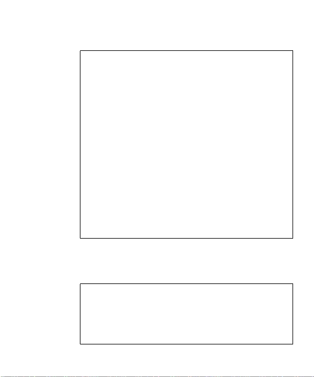
Sun StorEdge 6900 Series Multipathing Example
This Sun StorEdge 6900 series multipathing example contains the following
elements:
■ One Sun StorEdge T3+ array partner group
■ Two total LUNs
■ One 500-Gbyte RAID5 LUN per partner group
FIGURE 2-1 for a logical view of the Sun StorEdge 6900 series.
See
Host with HBA-0 and HBA-1
Switch
Switch
LUN0-500G
Passive-Master
LUN1-500G
Active-Alternate
Master
LUN0-10G
Active-MPDrive
LUN1-10G
Active-MPDrive1
SAN
Virtualization
Engine
(1)
Virtualization Engine Communications Traffic
Database
MPDrive
Carved LUNs
Masking
Storage I/O and
Logical Multipath
Drive
MPDrive 0
Logical Multipath
Drive
MPDrive 1
T3ES
(Master)
(0A - 1P)
(Alternate Master)
(1A - 0P)
LUN0-10G
Active-MPDrive 0
LUN1-10G
Active-MPDrive1
Virtualization
Engine
(2)
Switch
Switch
LUN0-500G
Active-Master
LUN1-500G
Passive-Alternate
Master
FIGURE 2-1 Sun StorEdge 6900 Series Logical View
Chapter 2 General Troubleshooting Procedures 11
Sun Proprietary/Confidential: Internal Use Only
Page 32

Currently, one 10-Gbyte VLUN is created from each physical LUN, for a total of two
VLUNs. The Sun StorEdge 6900 series has four possible physical paths to each Sun
StorEdge T3+ array volume (LUN).
Refer to
FIGURE 2-2, which illustrates primary data paths to the alternate master, and
FIGURE 2-3, which illustrates the primary data paths to the master Sun StorEdge T3+
array.
Host with HBA-0 and HBA-1
Switch
Switch
LUN0 - 500G
Passive-Master
LUN1 - 10G
Active-MPDrive 1
Virtualization
Engine (1)
LUN0 - 10G
Active-MPDrive 0
SAN
Database
MPDrive
Carved LUNs
Masking
Virtualization Engine Communications Traffic
Storage I/O and
Logical Multipath Drive
MPDrive 0
LUN0 - 10G
Active-MPDrive 0
LUN1 - 10G
Active-MPDrive 1
Virtualization
Engine (2)
Switch
Switch
LUN0 - 500G
Active-Master
LUN1 - 500G
Active Alternate Master
Logical Multipath Drive
MPDrive 1
T3ES
(Master) (0A - 1P)
(Alternate Master)
(1A - 0P)
FIGURE 2-2 Primary Data Paths to the Alternate Master
12 Sun StorEdge 3900 and 6900 2.0 Series Troubleshooting Guide • March 2003
Sun Proprietary/Confidential: Internal Use Only
LUN1 - 500G
Passive Alternate Master
Page 33

Host with HBA-0 and HBA-1
Switch
Switch
LUN0 - 500G
Passive - Master
LUN1 - 500G
Active Alternate Master
LUN1 - 10G
Active-MPDrive1
Virtualization
Engine (1)
LUN0 - 10G
Active-MPDrive0
SAN
Database
MPDrive
Carved LUNs
Masking
Storage I/O and
Virtualization Engine Communications Traffic
Logical Multipath Drive
MPDrive 0
Logical Multipath Drive
MPDrive 1
T3ES
(Master)
(0A - 1P)
(Alternate Master)
(1A - 0P)
LUN0 - 10G
Active-MPDrive0
LUN1 - 10G
Active-MPDrive1
Virtualization
Engine (2)
Switch
Switch
LUN0 - 500G
Active-Master
LUN1 - 500G
Passive Alternate Master
FIGURE 2-3 Primary Data Paths to the Master Sun StorEdge T3+ Array
To access the LUN on the alternate master, the Sun StorEdge T3+ array I/O could
travel:
■ From HBA-0 -> switch -> virtualization engine(1) -> switch -> alternate master
controller (primary route from HBA-0)
■ From HBA-0 -> switch -> virtualization engine(1) -> switch -> switch -> master
controller -> backend loop to alternate master (secondary route from HBA-0)
■ From HBA-1 -> switch -> virtualization engine(2) -> switch -> switch -> alternate
master controller (primary route from HBA-1)
■ From HBA-1 -> switch -> virtualization engine(2) -> switch -> master controller -
> backend loop to alternate master (secondary route from HBA-1)
Chapter 2 General Troubleshooting Procedures 13
Sun Proprietary/Confidential: Internal Use Only
Page 34

The host, using multipathing software, is presented with two primary (active) paths
for each LUN, allowing the host to route I/O through either or both HBAs.
If a path failure occurs before the second tier of Sun StorEdge network FC switch-8
and switch-16 switches, one of the paths is disabled—but the other path continues
sending I/O as it normally would and takes over the entire load. Refer to
FIGURE 2-4,
which illustrates a path failure before the second tier of switches.
No Sun StorEdge T3+ array failure is noted because of the redundant path, by way
of the Sun StorEdge network FC switch-8 and switch-16 switch T ports.
Host with HBA-0 and HBA-1
Switch
Switch
LUN0 - 500G
Passive-Master
LUN1 - 500G
Active Alternate Master
LUN1 - 10G
Active-MPDrive1
FAILURE
LUN0 - 10G
Active-MPDrive0
SAN
Database
MPDrive
Carved LUNs
Masking
Storage I/O and
Virtualization Engine Communications Traffic
Logical Multipath
Drive MPDrive 0
Logical Multipath
Drive MPDrive 1
T3ES
(Master)(0A - 1P)
(Alternate Master)
(1A - 0P)
LUN0 - 10G
Active-MPDrive 0
LUN1-10G
Active-MPDrive1
Virtualization
Engine (2)
Switch
Switch
LUN0 - 500G
Active-Master
LUN1 - 500G
Passive Alternate Master
FIGURE 2-4 Path Failure—Before the Second Tier of Switches
14 Sun StorEdge 3900 and 6900 2.0 Series Troubleshooting Guide • March 2003
Sun Proprietary/Confidential: Internal Use Only
Page 35

The virtualization engine recognizes the primary (active) and secondary (passive)
pathing for the LUNs, and routes the I/O to the primary controller—unless there is
a path failure to the primary path. In that case, the virtualization engine initiates a
LUN failover and routes the I/O through the secondary path (which, in turn, goes
through the interconnect cables). Refer to
FIGURE 2-5, which illustrates a path failure
where I/O is routed through both HBAs.
Host with HBA-0 and HBA-1
Switch
Switch
LUN0-500G
Passive-Master
LUN1-500G
Active Alternate Master
LUN1 - 10G
Active-MPDrive1
Virtualization
Engine(1)
FAILURE
LUN0 - 10G
Active-MPDrive0
SAN
Database
MPDrive
Carved LUNs
Storage I/O
and Virtualization Engine Communications Traffic
Masking
Logical
Multipath Drive
MPDrive 0
Logical
Multipath Drive
MPDrive 1
T3ES
(Master) (0A - 1P)
(Alternate Master)
(1A - 0P)
LUN0 - 10G
Active-MPDrive0
LUN1 - 10G
Active-MPDrive1
Virtualization
Engine(2)
Switch
Switch
LUN0 - 500 G
Active-Master
LUN1-500G
PassiveAlternate Master
FIGURE 2-5 Path Failure—I/O Routed Through Both HBAs
In the event of a path failure after the second tier of Sun StorEdge network FC
switch-8 and switch-16 switches (or in the event that both T ports fail between the
switches), the virtualization engine forces a LUN failover of the affected Sun
StorEdge T3+ array and routes all I/O to its secondary path.
From the host side, nothing has changed: all I/O is routed through both HBAs (refer
FIGURE 2-5).
to
Chapter 2 General Troubleshooting Procedures 15
Sun Proprietary/Confidential: Internal Use Only
Page 36

Multipathing Options in the Sun StorEdge 6900 Series
The presence of the virtualization engine makes multipathing in a Sun StorEdge
6900 series environment challenging.
Unlike Sun StorEdge T3+ array and Sun StorEdge network FC switch-8 and switch16 switch installations (which present primary and secondary pathing options), the
virtualization engines present only primary pathing options to the data host. The
virtualization engines handle all failover and failback operations and mask those
operations from the multipathing software on the data host.
The following example illustrates a Sun StorEdge Traffic Manager (MPxIO) software
problem on a Sun StorEdge 6900 series system.
# /usr/sbin/luxadm display
/dev/rdsk/c6t29000060220041F96257354230303052d0s2
DEVICE PROPERTIES for disk: /dev/rdsk/
c6t29000060220041F96257354230303052d0s2
Status(Port A): O.K.
Status(Port B): O.K.
Vendor: SUN
Product ID: SESS01
WWN(Node): 2a000060220041f4
WWN(Port A): 2b000060220041f4
WWN(Port B): 2b000060220041f9
Revision: 080C
Serial Num: Unsupported
Unformatted capacity: 102400.000 MBytes
Write Cache: Enabled
Read Cache: Enabled
Minimum prefetch: 0x0
Maximum prefetch: 0x0
Device Type: Disk device
Path(s):
/dev/rdsk/c6t29000060220041F96257354230303052d0s2
/devices/scsi_vhci/ssd@g29000060220041f96257354230303052:c,raw
Controller /devices/pci@6,4000/SUNW,qlc@2/fp@0,0
Device Address 2b000060220041f4,0
Class primary
State ONLINE
Controller /devices/pci@6,4000/SUNW,qlc@3/fp@0,0
Device Address 2b000060220041f9,0
Class primary
State ONLINE
16 Sun StorEdge 3900 and 6900 2.0 Series Troubleshooting Guide • March 2003
Sun Proprietary/Confidential: Internal Use Only
Page 37

Note that in the Class and State fields, the virtualization engines are presented as
two primary ONLINE devices. The current Sun StorEdge Traffic Manager software
design does not enable you to manually halt the I/O (that is, you cannot perform a
failover to the secondary path) when only primary devices are present.
Manually Halting the I/O
As an alternative to using the Sun StorEdge Traffic Manager (MPxIO) software, you
can manually halt the I/O using one of two methods:
■ Quiesce the I/O
■ Unconfigure the c2 path
These methods are explained in the following sections.
▼ To Quiesce the I/O
1. Determine the path you want to disable.
2. Type:
# cfgadm -c unconfigure
device
▼ To Unconfigure the c2 Path
1. Type:
# cfgadm -al
Ap_Id Type Receptacle Occupant Condition
c0 scsi-bus connected configured unknown
c0::dsk/c0t0d0 disk connected configured unknown
c0::dsk/c0t1d0 disk connected configured unknown
c1 scsi-bus connected configured unknown
c1::dsk/c1t6d0 CD-ROM connected configured unknown
c2 fc-fabric connected configured unknown
c2::210100e08b23fa25 unknown connected unconfigured unknown
c2::2b000060220041f4 disk connected configured unknown
c3 fc-fabric connected configured unknown
c3::210100e08b230926 unknown connected unconfigured unknown
c3::2b000060220041f9 disk connected configured unknown
c4 fc-private connected unconfigured unknown
c5 fc connected unconfigured unknown
Chapter 2 General Troubleshooting Procedures 17
Sun Proprietary/Confidential: Internal Use Only
Page 38

2. Using the Storage Automated Diagnostic Environment GUI Topology, determine
which virtualization engine is in the path you need to disable.
3. Use the worldwide name (WWN) of the virtualization engine that is in the
unconfigure command, as follows:
# cfgadm -c unconfigure c2::2b000060220041f4
# cfgadm -al
Ap_Id Type Receptacle Occupant Condition
c0 scsi-bus connected configured unknown
c0::dsk/c0t0d0 disk connected configured unknown
c0::dsk/c0t1d0 disk connected configured unknown
c1 scsi-bus connected configured unknown
c1::dsk/c1t6d0 CD-ROM connected configured unknown
c2 fc-fabric connected unconfigured unknown
c2::210100e08b23fa25 unknown connected unconfigured unknown
c2::2b000060220041f4 disk connected unconfigured unknown
c3 fc-fabric connected configured unknown
c3::210100e08b230926 unknown connected unconfigured unknown
c3::2b000060220041f9 disk connected configured unknown
c4 fc-private connected unconfigured unknown
c5 fc connected unconfigured unknown
4. Verify that the I/O has halted.
Disabling the path halts the I/O only up to the A3 to B3 link (see
FIGURE 5-8). I/O
continues to move over the T1 and T2 data paths, as well as the A4 to B4 links to the
Sun StorEdge T3+ array.
Suspending the I/O
Use one of the following methods to suspend the I/O while the failover occurs:
■ Stop all customer applications that are accessing the Sun StorEdge T3+ array.
■ Manually pull the link from the Sun StorEdge T3+ array to the switch and wait
for a Sun StorEdge T3+ array logical unit number (LUN) failover.
■ After the failover occurs, replace the cable and proceed with the testing and
FRU isolation.
■ After the testing and any FRU replacement are finished, return the Controller
state back to the default by using virtualization engine failback. Refer to “To
Failback the Virtualization Engine” on page 120.
18 Sun StorEdge 3900 and 6900 2.0 Series Troubleshooting Guide • March 2003
Sun Proprietary/Confidential: Internal Use Only
Page 39

Note – To confirm that a failover is occurring, open a Telnet session to the Sun
StorEdge T3+ array and check the output of port listmap.
Another, but slower, method is to run the runsecfg script and verify the
virtualization engine maps by polling them against a live system.
Caution – During the failover, small computer systems interface (SCSI) errors will
occur on the data host and a brief suspension of I/O will occur.
▼ To Put the c2 Path Back into Production
1. Type:
# cfgadm -c configure c2::2b000060220041f4
2. Verify that I/O has resumed on all paths.
Chapter 2 General Troubleshooting Procedures 19
Sun Proprietary/Confidential: Internal Use Only
Page 40

▼
To View the Dynamic Multi-Pathing (DMP) Properties
1. Type:
# vxdisk list Disk_1
Device: Disk_1
devicetag: Disk_1
type: sliced
hostid: diag.xxxxx.xxx.COM
disk: name=t3dg02 id=1010283311.1163.diag.xxxxx.xxx.com
group: name=t3dg id=1010283312.1166.diag.xxxxx.xxx.com
flags: online ready private autoconfig nohotuse autoimport imported
pubpaths: block=/dev/vx/dmp/Disk_1s4 char=/dev/vx/rdmp/Disk_1s4
privpaths: block=/dev/vx/dmp/Disk_1s3 char=/dev/vx/rdmp/Disk_1s3
version: 2.2
iosize: min=512 (bytes) max=2048 (blocks)
public: slice=4 offset=0 len=209698816
private: slice=3 offset=1 len=4095
update: time=1010434311 seqno=0.6
headers: 0 248
configs: count=1 len=3004
logs: count=1 len=455
Defined regions:
config priv 000017-000247[000231]: copy=01 offset=000000 enabled
config priv 000249-003021[002773]: copy=01 offset=000231 enabled
log priv 003022-003476[000455]: copy=01 offset=000000 enabled
Multipathing information:
numpaths: 2
c20t2B000060220041F4d0s2 state=enabled
c23t2B000060220041F9d0s2 state=enabled
# vxdmpadm listctlr all
CTLR-NAME ENCLR-TYPE STATE ENCLR-NAME
=====================================================
c0 OTHER_DISKS ENABLED OTHER_DISKS
c2 SENA ENABLED SENA0
c3 SENA ENABLED SENA0
c20 Disk ENABLED Disk
c23 Disk ENABLED Disk
The vxdisk output includes two physical paths to the LUN:
■ c20t2B000060220041F4d0s2
■ c23t2B000060220041F9d0s2
Both of these paths are currently enabled with DMP.
20 Sun StorEdge 3900 and 6900 2.0 Series Troubleshooting Guide • March 2003
Sun Proprietary/Confidential: Internal Use Only
Page 41

2. Use the luxadm (1M) command to display further information about the underlying LUN.
# /usr/sbin/luxadm display /dev/rdsk/c20t2B000060220041F4d0s2
DEVICE PROPERTIES for disk: /dev/rdsk/c20t2B000060220041F4d0s2
Status(Port A): O.K.
Vendor: SUN
Product ID: SESS01
WWN(Node): 2a000060220041f4
WWN(Port A): 2b000060220041f4
Revision: 080C
Serial Num: Unsupported
Unformatted capacity: 102400.000 MBytes
Write Cache: Enabled
Read Cache: Enabled
Minimum prefetch: 0x0
Maximum prefetch: 0x0
Device Type: Disk device
Path(s):
/dev/rdsk/c20t2B000060220041F4d0s2
/devices/pci@a,2000/pci@2/SUNW,qlc@4/fp@0,0
ssd@w2b000060220041f4,0:c,raw
# luxadm display /dev/rdsk/c23t2B000060220041F9d0s2
DEVICE PROPERTIES for disk: /dev/rdsk/c23t2B000060220041F9d0s2
Status(Port A): O.K.
Vendor: SUN
Product ID: SESS01
WWN(Node): 2a000060220041f9
WWN(Port A): 2b000060220041f9
Revision: 080C
Serial Num: Unsupported
Unformatted capacity: 102400.000 MBytes
Write Cache: Enabled
Read Cache: Enabled
Minimum prefetch: 0x0
Maximum prefetch: 0x0
Device Type: Disk device
Path(s):
/dev/rdsk/c23t2B000060220041F9d0s2
/devices/pci@e,2000/pci@2/SUNW,qlc@4/fp@0,0/
ssd@w2b000060220041f9,0:c,raw
Chapter 2 General Troubleshooting Procedures 21
Sun Proprietary/Confidential: Internal Use Only
Page 42

To Put the DMP-Enabled Paths Back into Production
▼
1. Type:
# vxdmpadm enable ctlr=<cn>
2. Verify that the path has been reenabled by typing:
# vxdmpadm listctlr all
22 Sun StorEdge 3900 and 6900 2.0 Series Troubleshooting Guide • March 2003
Sun Proprietary/Confidential: Internal Use Only
Page 43

CHAPTER
3
Troubleshooting Tools
This chapter contains the following information related to tools used to troubleshoot
the Sun StorEdge 3900 or 6900 series components.
■ “Storage Automated Diagnostic Environment 2.2” on page 23
■ “Microsoft Windows 2000 System Errors” on page 26
■ “Command Line Test Examples” on page 27
■ “Monitoring Sun StorEdge T3 and T3+ Arrays Using the Explorer Data Collection
Utility” on page 29
■ “Monitoring Host Bus Adapters (HBAs) Using QLogic SANblade Manager” on
page 32
Storage Automated Diagnostic Environment 2.2
Check the internal status of the Sun StorEdge 3900 or 6900 series systems using the
Storage Automated Diagnostic Environment utility, version 2.2.
The Storage Automated Diagnostic Environment is installed on every Storage
Service Processor that ships with the unit. All that is needed is web browser access
to the Storage Service Processor.
In non-Sun host configurations such as Microsoft Windows 2000, the Storage
Automated Diagnostic Environment will be able to monitor the internals of the
storage unit (switches, virtualization engines, and the Sun StorEdge T3+ arrays), but
will not be able to completely monitor the host-to-storage unit link (the HBA to
switch). Certain conditions will be noted by Storage Automated Diagnostic
Environment, however, such as a port going offline, or increasing Fibre Channel
errors on the port.
Sun Proprietary/Confidential: Internal Use Only
23
Page 44

Example Topology
In the Storage Automated Diagnostic Environment topology shown in FIGURE 3-1,
the internel components of a Sun StorEdge 3910 system are shown. There is also a
Solaris host (diag221) and the Storage Service Processor (diag156) in the view. What
is missing is the Microsoft Windows 2000 host, which is also connected.
FIGURE 3-1 Storage Automated Diagnostic Environment Example Topology
24 Sun StorEdge 3900 and 6900 Series 2.0 Troubleshooting Guide • March 2003
Sun Proprietary/Confidential: Internal Use Only
Page 45

Generating Component-Specific Event Grids
The Storage Automated Diagnostic Environment generates component-specific event
grids that describe the severity of an event, tell whether action is required, provide a
description of the event, and recommended action. Refer to Chapters 5 through 9 of
this troubleshooting guide for component-specific event grids.
▼ To Customize an Event Report
1. Choose the Event Grid link on the the Storage Automated Diagnostic Environment Help menu.
2. Select the criteria from the Storage Automated Diagnostic Environment event
grid, like the one shown in in
TABLE3-1 Event Grid Sorting Criteria
Category Component Event Type Severity Action
• All (default)
• Sun StorEdge
A3500FC array
• Sun StorEdge A5000
array
• Agent
• Host
• Message
• Sun Switch
• Sun StorEdge T3+
array
• Tape
• Virtualization engine
• All
(default)
• Backplane
• Controller
• Disk
• Interface
• LUN
• Port
• Power
• Agent Deinstall
• Agent Install
• Alarm
•FC+
• Alternate Master -
• Audit
• Communication Established
• Communication Lost
• Discovery
• Heartbeat
• Insert Component
• Location Change
• Patch Info
• Quiesce End
• Quiesce Start
• Removal
• Remove Component
• State Change +
(from offline to online)
• State Change (from online to offline)
• Statistics
• Backup
TABLE 3-1.
critical (error)
alert (warning)
system down
Yes—This
event is
actionable
and is sent to
the RSS/SRS
providers
No—This
event is
nonactionable
Chapter 3 Troubleshooting Tools 25
Sun Proprietary/Confidential: Internal Use Only
Page 46

Microsoft Windows 2000 System Errors
You can view Microsoft Windows 2000 errors through the Event Properties System
Log. The types of errors that would indicate a Sun StorEdge T3+ Array Failover
Driver issue have the Source "Jafo". An example is shown in
You should also look for other events such as any HBA driver-related events
(qla2200, for example) or disk-related events.
FIGURE 3-2.
FIGURE 3-2 Microsoft Windows 2000 Event Properties System Log
26 Sun StorEdge 3900 and 6900 Series 2.0 Troubleshooting Guide • March 2003
Sun Proprietary/Confidential: Internal Use Only
Page 47

Command Line Test Examples
To run a single Sun StorEdge diagnostic test from the command line rather than
through the Storage Automated Diagnostic Environment interface, you must log in
to the appropriate host or slave for testing the components.
The following two tests, qlctest (1M) and switchtest (1M), are provided as
examples.
qlctest(1M)
The qlctest(1M) test comprises several subtests that test the functions of the Sun
StorEdge PCI dual Fibre Channel (FC) host adapter board. This board is an HBA that
has diagnostic support. This diagnostic test is not scalable.
CODE EXAMPLE 3-1 qlctest(1M)
# /opt/SUNWstade/Diags/bin/qlctest -v -o "dev=\
/devices/pci@6,4000/SUNW,qlc@3/fp@0,0:devctl|run_connect\
=Yes|mbox=Disable|ilb=Disable|ilb_10=Disable|elb=Enable"
"qlctest: called with options: dev=/devices/pci@6,4000/SUNW,qlc@3/
fp@0,0:devctl|run_connect=Yes|mbox=Disable|ilb=Disable|ilb_10=Disable|el
b=Enable"
"qlctest: Started."
"Program Version is 4.0.1"
"Testing qlc0 device at /devices/pci@6,4000/SUNW,qlc@3/fp@0,0:devctl."
"QLC Adapter Chip Revision = 1, Risc Revision = 3,
Frame Buffer Revision = 1029, Riscrom Revision = 4,
Driver Revision = 5.a-2-1.15 "
"Running ECHO command test with pattern 0x7e7e7e7e"
"Running ECHO command test with pattern 0x1e1e1e1e"
"Running ECHO command test with pattern 0xf1f1f1f1"
...
"Running ECHO command test with pattern 0x4a4a4a4a"
"Running ECHO command test with pattern 0x78787878"
"Running ECHO command test with pattern 0x25252525"
"FCODE revision is ISP2200 FC-AL Host Adapter Driver: 1.12 01/01/16"
"Firmware revision is 2.1.7f"
"Running CHECKSUM check"
"Running diag selftest"
"qlctest: Stopped successfully."
Chapter 3 Troubleshooting Tools 27
Sun Proprietary/Confidential: Internal Use Only
Page 48

switchtest(1M)
switchtest(1M) diagnoses the Sun StorEdge network FC switch-8 and switch-16
switch devices. The switchtest process also provides command-line access to
switch diagnostics. switchtest supports testing on local and remote switches.
switchtest runs the port diagnostic on connected switch ports. While
switchtest is running, the switch ports monitor the port statistics and check the
chassis status.
CODE EXAMPLE 3-2 switchtest(1M)
# /opt/SUNWstade/Diags/bin/switchtest -v -o "dev=\
2:192.168.0.30:0x0|xfersize=200"\
"switchtest: called with options: dev=2:192.168.0.30:0x0|xfersize=200"
"switchtest: Started."
"Testing port: 2"
"Using ip_addr: 192.168.0.30, fcaddr: 0x0 to access this port."
"Chassis Status for Device: Switch Power: OK Temp: OK 23.0c Fan 1: OK Fan
2: OK"
"Testing Device: Switch Port: 2 Pattern: 0x7e7e7e7e"
"Testing Device: Switch Port: 2 Pattern: 0x1e1e1e1e"
"Testing Device: Switch Port: 2 Pattern: 0xf1f1f1f1"
"Testing Device: Switch Port: 2 Pattern: 0xb5b5b5b5"
"Testing Device: Switch Port: 2 Pattern: 0x4a4a4a4a"
"Testing Device: Switch Port: 2 Pattern: 0x78787878"
"Testing Device: Switch Port: 2 Pattern: 0xe7e7e7e7"
"Testing Device: Switch Port: 2 Pattern: 0xaa55aa55"
"Testing Device: Switch Port: 2 Pattern: 0x7f7f7f7f"
"Testing Device: Switch Port: 2 Pattern: 0x0f0f0f0f"
"Testing Device: Switch Port: 2 Pattern: 0x00ff00ff"
"Testing Device: Switch Port: 2 Pattern: 0x25252525"
"Port: 2 passed all tests on Switch"
"switchtest: Stopped successfully."
All Storage Automated Diagnostic Environment diagnostic tests are located in
/opt/SUNWstade/Diags/bin. Refer to the Storage Automated Diagnostic
Environment User’s Guide for a complete list of tests, subtests, options, and
restrictions.
28 Sun StorEdge 3900 and 6900 Series 2.0 Troubleshooting Guide • March 2003
Sun Proprietary/Confidential: Internal Use Only
Page 49

Monitoring Sun StorEdge T3 and T3+ Arrays Using the Explorer Data Collection Utility
The Explorer Data Collection Utility script is included on the Storage Service
Processor in the /export/packages directory.
The Explorer Data Collection Utility is not installed by default, but can be installed
during rack setup. Customer-specific site information can be entered at that time.
To find out more about the Explorer Data Collection Utility, you can access the web
site with the following URL:
http://webhome.eng/mdeSW/Project/Explorer.html
▼ To Install the Explorer Data Collection Utility on
the Storage Service Processor
1. Type:
# cd /export/packages
# pkgadd -d . SUNWexplo
2. When you are prompted for site-specific information during the installation
process, you can optionally click Return to accept the blank defaults.
Caution – Do not accept automatic emailing of the Explorer Data Collection Utility
output unless the Storage Service Processor is set up to handle mail correctly.
Automatic Email Submission
Would you like all explorer output to be sent to:
explorer-database-americas@sun.com
at the completion of explorer when -mail or -e is specified?
[y,n] n
Chapter 3 Troubleshooting Tools 29
Sun Proprietary/Confidential: Internal Use Only
Page 50

3. Before running the Explorer Data Collection Utility, make sure that the switch and
Sun StorEdge T3+ array information is added to the proper
/opt/SUNWexplo/etc files.
Example
Type switch information in the /opt/SUNWexplo/etc/saninput.txt file. Edit
the file and add the switch information, as shown in
CODE EXAMPLE 3-3 Editing Switch Information Using vi
# vi saninput.txt
# Input file for extended data collection
# Format is SWITCH SWITCH-TYPE PASSWORD LOGIN
# Valid switch types are ancor and brocade
# LOGIN is required for brocade switches, the default is admin
sw1a ancor
sw1b ancor
sw2a ancor
sw2b ancor
:wq!
4. Type Sun StorEdge T3+ array information in the /opt/SUNWexplo/etc/ t3input.txt file.
CODE EXAMPLE 3-3.
5. Type the password for your specific site.
CODE EXAMPLE 3-4 Editing Sun StorEdge T3+ Array Information Using vi
# vi t3input.txt
# Input file for extended data collection
# Format is HOST PASSWORD
t3b0 xxxx
t3b2 xxxx
t3b3 xxxx
:wq!
Note – xxxx represents Sun StorEdge T3+ array passwords.
30 Sun StorEdge 3900 and 6900 Series 2.0 Troubleshooting Guide • March 2003
Sun Proprietary/Confidential: Internal Use Only
Page 51

■ You can now run /opt/SUNWexplo/bin/explorer for information about the
Storage Service Processor operating system, the Sun StorEdge network FC switch8 or switch-16 switch, and Sun StorEdge T3+ array information that you can use
for troubleshooting purposes.
■ A tar/gzip file is put in the /opt/SUNWexplo/output/tar/gzip file
directory. You can send the tar/gzip file to Sun Solution Center for evaluation.
■ The Sun StorEdge network FC switch-8 and switch-16 switch information is
placed in the san directory of the tar file.
■ Sun StorEdge T3+ array information is placed in the disk’s /t3 directory.
Chapter 3 Troubleshooting Tools 31
Sun Proprietary/Confidential: Internal Use Only
Page 52

Monitoring Host Bus Adapters (HBAs) Using QLogic SANblade Manager
The most effective way to retrieve HBA status and information is by using the HBA
manufacturer’s utility, such as the Qlogic SANblade Manager software provided by
Qlogic for their HBAs. This software is freely downloadable from Qlogic’s website
(http://www.qlogic.com).
Note – Other manufacturer’s utilities, such as LightPulse’s Emulex, are needed for
other HBA’s, such as Emulex HBAs.
Use the Qlogic SANblade Manager to extract information about:
■ HBA Driver versions
■ Firmware versions
■ A primitive topology view
■ A LUN listing
■ Diagnostics on the HBA
32 Sun StorEdge 3900 and 6900 Series 2.0 Troubleshooting Guide • March 2003
Sun Proprietary/Confidential: Internal Use Only
Page 53

FIGURE 3-3 Qlogic SANblade Manager HBA Driver and Firmware Versions
Chapter 3 Troubleshooting Tools 33
Sun Proprietary/Confidential: Internal Use Only
Page 54

QLogic SANblade Manager is also useful for viewing a primitive topology and a
LUN listing.
FIGURE 3-4 QLogic SANblade Manager Diagnostics
Note – Differing HBA manufacturer’s may bundle different features with their
tools. The information in this guide is written with the assumption of Qlogic
software usage.
34 Sun StorEdge 3900 and 6900 Series 2.0 Troubleshooting Guide • March 2003
Sun Proprietary/Confidential: Internal Use Only
Page 55

CHAPTER
4
Troubleshooting Ethernet Hubs
The Sun StorEdge 3900 and 6900 series uses an Ethernet hub as the backbone for the
internal service network. The allocation of Ethernet ports is as follows:
■ One for the Storage Service Processor (per subsystem)
■ One for each FC switch
■ One for each virtualization engine
■ Two for each Sun StorEdge T3+ array partner group
■ One for the Ethernet hub that is installed on the second Sun StorEdge Expansion
Cabinet in the Sun StorEdge 3960 and 6960 series systems
Note – Information about LED status lights, power information, and front panel
settings can be found in the 3Com document SuperStack 3 Baseline Hub 12-Port TP
User Guide or SuperStack 3 Baseline Hub 24-Port TP User Guide, available at
http://www.3com.com.
For repair and replacement procedures, refer to the Sun StorEdge 3900 and 6900 Series
Reference and Service Guide .
Sun Proprietary/Confidential: Internal Use Only
35
Page 56

36 Sun StorEdge 3900 and 6900 Series 2.0 Troubleshooting Guide • March 2003
Sun Proprietary/Confidential: Internal Use Only
Page 57

CHAPTER
5
Troubleshooting the Fibre Channel (FC) Links
FC links diagnose Sun StorEdge network FC components in a SAN or a direct
attached storage (DAS) environment. linktest(1M), which tests the health of the
FC links, is available only from the Test from Topology view of the Storage
Automated Diagnostic Environment GUI.
Note – linktest tests both ends of the link segment and enters a guided isolation
when a fault is detected.
Faults can be detected in one of two ways: when linktest sends an alert on a bad
or intermittent link, or when a red link appears on the topology graph, indicating a
failure.
This chapter contains the following sections:
■ “FC Links” on page 38
■ “Troubleshooting the A1 or B1 FC Link” on page 42
■ “Troubleshooting the A2 or B2 FC Link” on page 49
■ “Troubleshooting the A3 or B3 FC Link” on page 54
■ “Troubleshooting the A4 or B4 FC Link” on page 60
Sun Proprietary/Confidential: Internal Use Only
37
Page 58

FC Links
The following sections provide troubleshooting information for the basic
components and FC links, listed in
TABLE5-1 FC Links
Link Provides FC Link Between These Components
A1 to B1 Data host, sw1a, and sw1b
A2 sw1a and v1a*
B2 sw1b and v1b*
A3 v1a and sw2a*
B3 v1b and sw2b*
A4 Master Sun StorEdge T3+ array and the “A” path switch
B4 Alternate master Sun StorEdge T3+ array and the “B” path switch
T1 to T2 sw2a and sw2b*
* Sun StorEdge 6900 1.1 Series only
By using the Storage Automated Diagnostic Environment, you should be able to
isolate the problem to one particular segment of the configuration.
TABLE 5-1.
Note – The information found in this section is based on the assumption that the
Storage Automated Diagnostic Environment is running on the data host, and that it
is configured to monitor host errors.
The following diagrams provide troubleshooting information for the basic
components and FC links specific to the Sun StorEdge 3900 1.1 series (shown in
FIGURE 5-1), and the Sun StorEdge 6900 1.1 series (shown in FIGURE 5-2).
Note – An actual Sun StorEdge 3900 or 6900 series configuration could have more
Sun StorEdge T3+ arrays than are shown in FIGURE 5-1 and FIGURE 5-2.
38 Sun StorEdge 3900 and 6900 Series 2.0 Troubleshooting Guide • March 2003
Sun Proprietary/Confidential: Internal Use Only
Page 59

FC Link Diagrams
FIGURE 5-1 shows the basic components and the FC links for a Sun StorEdge 3900
series system:
■ A1 to B1—HBA to Sun StorEdge network FC switch-8 and switch-16 switch link
■ A4 to B4—Sun StorEdge network FC switch-8 and switch-16 switch to Sun
StorEdge T3+ array link
HOST
HBA-A
A1
sw1a sw1b
T3+ alternate master
A4
T3+ Master
HBA-B
B1
B4
FIGURE 5-1 Sun StorEdge 3900 Series FC Link Diagram
Chapter 5 Troubleshooting the Fibre Channel (FC) Links 39
Sun Proprietary/Confidential: Internal Use Only
Page 60

TABLE 5-2 and FIGURE 5-2 shows the basic components and the FC links for a Sun
StorEdge 6900 series system:
TABLE5-2 Ax to Bx FC Links.
Link Provides FC Link Between These Components
A1 to B1 HBA to Sun StorEdge network FC switch-8 and switch-16
switch link
A2 to B2 Sun StorEdge network FC switch-8 and switch-16 switch to
virtualization engine link on the host side
A3 to B3 Sun StorEdge network FC switch-8 and switch-16 switch to the
virtualization engine link on the device side
A4 to B4 Sun StorEdge network FC switch-8 and switch-16 switch to Sun
StorEdge T3+ array link
T1 to T2 T port switch-to-switch link
40 Sun StorEdge 3900 and 6900 Series 2.0 Troubleshooting Guide • March 2003
Sun Proprietary/Confidential: Internal Use Only
Page 61

HOST
A2
A3
sw2a
sw1a
v1a
A4
A1
HBA-A
T1
T2
T3+ alternate master
T3+ Master
HBA-B
B1
sw1b
B2
v1b
B3
sw2b
B4
FIGURE 5-2 Sun StorEdge 6900 Series FC Link Diagram
Chapter 5 Troubleshooting the Fibre Channel (FC) Links 41
Sun Proprietary/Confidential: Internal Use Only
Page 62

Troubleshooting the A1 or B1 FC Link
The A1 or B1 link is the FC link from the HBA to the switch.
What happens when a FC link fails depends on the system. If a problem occurs with
the A1 or B1 FC link:
■ In a Sun StorEdge 3900 series system, the Sun StorEdge T3+ array will fail over.
■ In a Sun StorEdge 6900 series system, no Sun StorEdge T3+ array will fail over,
but an error with the FC link can cause a path to go offline.
42 Sun StorEdge 3900 and 6900 Series 2.0 Troubleshooting Guide • March 2003
Sun Proprietary/Confidential: Internal Use Only
Page 63

FIGURE 5-3, FIGURE 5-4, and FIGURE 5-5 are examples of A1 or B1 link notification
events.
Site : FSDE LAB Broomfield CO
Source : diag.xxxxx.xxx.com
Severity : Normal
Category : Message Key: message:diag.xxxxx.xxx.com
EventType: LogEvent.driver.LOOP_OFFLINE
EventTime: 01/08/2002 14:34:45
Found 1 ’driver.LOOP_OFFLINE’ error(s) in logfile: /var/adm/messages on
diag.xxxxx.xxx.com (id=80fee746):
info: Loop Offline
Jan 8 14:34:25 WWN: Received 2 ’Loop Offline’ message(s) [threshold is 1
in 5mins] Last-Message: ’diag.xxxxx.xxx.com qlc: [ID 686697 kern.info] NOTICE:
Qlogic qlc(0): Loop OFFLINE ’
FIGURE 5-3 Data Host Notification of Intermittent Problems
Site : FSDE LAB Broomfield CO
Source : diag.xxxxx.xxx.com
Severity : Normal
Category : Message Key: message:diag.xxxxx.xxx.com
EventType: LogEvent.driver.MPXIO_offline
EventTime: 01/08/2002 14:48:02
Found 2 ’driver.MPXIO_offline’ warning(s) in logfile: /var/adm/messages on
diag.xxxxx.xxx.com (id=80fee746):
Jan 8 14:47:07 WWN:2b000060220041f9 diag.xxxxx.xxx.com mpxio: [ID
779286 kern.info] /scsi_vhci/ssd@g29000060220041f96257354230303053
(ssd19) multipath status: degraded, path /pci@6,4000/SUNW,qlc@3/fp@0,0
(fp1) to target address: 2b000060220041f9,1 is offline
Jan 8 14:47:07 WWN:2b000060220041f9 diag.xxxxx.xxx.com mpxio: [ID
779286 kern.info] /scsi_vhci/ssd@g29000060220041f96257354230303052
(ssd18) multipath status: degraded, path /pci@6,4000/SUNW,qlc@3/fp@0,0
(fp1) to target address: 2b000060220041f9,0 is offline
FIGURE 5-4 Data Host Notification of Severe Link Error
Chapter 5 Troubleshooting the Fibre Channel (FC) Links 43
Sun Proprietary/Confidential: Internal Use Only
Page 64

Site : FSDE LAB Broomfield CO
Source : diag.xxxxx.xxx.com
Severity : Normal
Category : Switch Key: switch:100000c0dd0057bd
EventType: StateChangeEvent.X.port.6
EventTime: 01/08/2002 14:54:20
’port.6’ in SWITCH diag-sw1a (ip=192.168.0.30) is now Unknown (statusstate changed from ’Online’ to ’Admin’):
FIGURE 5-5 Storage Service Processor Notification
Note – An A1 or B1 FC link error can cause a port in sw1a or sw1b to change state.
44 Sun StorEdge 3900 and 6900 Series 2.0 Troubleshooting Guide • March 2003
Sun Proprietary/Confidential: Internal Use Only
Page 65

Verifying the Data Host
The following example shows an error in the A1 or B1 FC link, which can cause a
path to go offline in the multipathing software.
CODE EXAMPLE 5-1 luxadm(1M) Display
# /usr/sbin/luxadm display
/dev/rdsk/c6t29000060220041F96257354230303052d0s2
DEVICE PROPERTIES for disk: /dev/rdsk/
c6t29000060220041F96257354230303052d0s2
Status(Port A): O.K.
Status(Port B): O.K.
Vendor: SUN
Product ID: SESS01
WWN(Node): 2a000060220041f4
WWN(Port A): 2b000060220041f4
WWN(Port B): 2b000060220041f9
Revision: 080C
Serial Num: Unsupported
Unformatted capacity: 102400.000 MBytes
Write Cache: Enabled
Read Cache: Enabled
Minimum prefetch: 0x0
Maximum prefetch: 0x0
Device Type: Disk device
Path(s):
/dev/rdsk/c6t29000060220041F96257354230303052d0s2
/devices/scsi_vhci/ssd@g29000060220041f96257354230303052:c,raw
Controller /devices/pci@6,4000/SUNW,qlc@3/fp@0,0
Device Address 2b000060220041f9,0
Class primary
State OFFLINE
Controller /devices/pci@6,4000/SUNW,qlc@2/fp@0,0
Device Address 2b000060220041f4,0
Class primary
State ONLINE
...
Chapter 5 Troubleshooting the Fibre Channel (FC) Links 45
Sun Proprietary/Confidential: Internal Use Only
Page 66

An error in the A1 or B1 FC link can also cause a device to enter the “unusable” state
in cfgadm -al, as shown in
CODE EXAMPLE 5-2 cfgadm -al Display
# /usr/sbin/cfgadm -al
Ap_Id Type Receptacle Occupant Condition
c0 scsi-bus connected configured unknown
c0::dsk/c0t0d0 disk connected configured unknown
c0::dsk/c0t1d0 disk connected configured unknown
c1 scsi-bus connected configured unknown
c1::dsk/c1t6d0 CD-ROM connected configured unknown
c2 fc-fabric connected configured unknown
c2::210100e08b23fa25 unknown connected unconfigured unknown
c2::2b000060220041f4 disk connected configured unknown
c3 fc-fabric connected configured unknown
c3::2b000060220041f9 disk connected configured unusable
c4 fc-private connected unconfigured unknown
c5 fc connected unconfigured unknown
CODE EXAMPLE 5-2.
FRU Tests Available for the A1 or B1 FC Link Segment
The following FRU tests are available for the A1 or B1 FC link segment. All
diagnostics are located in /opt/SUNWstade/Diags/bin. Refer to the man pages
for more details.
■ HBA—qlctest(1M)
■ Available only if the Storage Automated Diagnostic Environment is installed
on a data host
■ Causes HBA to go offline and online during tests
■ Switch —switchtest(1M)
■ Can be run while the link is still cabled and online (connected to HBA)
■ Can be run only from the Storage Service Processor.
■ The dev option to switchtest is in the following format:
Port:IP-Address:FCAddress
The FCAddress can be set to 0x0.
Note – If you are testing an A1 or B1 FC link that is connected to an HBA, you must
specify a payload of 200 bytes or less. This is a limitation in the HBA applicationspecific integrated circuit (ASIC).
46 Sun StorEdge 3900 and 6900 Series 2.0 Troubleshooting Guide • March 2003
Sun Proprietary/Confidential: Internal Use Only
Page 67

CODE EXAMPLE 5-3 switchtest(1M) Called With Options
# /opt/SUNWstade/Diags/bin/switchtest -v -o "dev=2:192.168.0.30:0"
"switchtest: called with options: dev=2:192.168.0.30:0"
"switchtest: Started."
"Testing port: 2"
"Using ip_addr: 192.168.0.30, fcaddr: 0x0 to access this port."
"Chassis Status for Device: Switch Power: OK Temp: OK 23.0c Fan 1: OK
Fan 2: OK "
02/06/02 15:09:45 diag Storage Automated Diagnostic Environment MSGID 4001
switchtest.WARNING
switch0: "Maximum transfer size for a FABRIC port is 200. Changing
transfer size 2000 to 200"
"Testing Device: Switch Port: 2 Pattern: 0x7e7e7e7e"
"Testing Device: Switch Port: 2 Pattern: 0x1e1e1e1e"
Note – The Storage Automated Diagnostic Environment automatically resets the
transfer size if it notes that it is about to test a switch to the HBA connection. This is
done both in the Storage Automated Diagnostic Environment GUI and from the
command-line interface (CLI).
Chapter 5 Troubleshooting the Fibre Channel (FC) Links 47
Sun Proprietary/Confidential: Internal Use Only
Page 68

▼
To Isolate the A1 or B1 FC Link
To isolate the A1 or B1 link, which is the FC link from the HBA to the switch, follow
these steps:
1. Quiesce the I/O on the A1 or B1 FC link path.
2. Run switchtest(1M) or qlctest(1M) to test the entire link.
3. Break the connection by uncabling the link.
4. Insert a loopback connector into the switch port.
5. Rerun switchtest. a. If switchtest fails, replace the gigabit interface converter (GBIC) and rerun
switchtest.
b. If switchtest fails again, replace the switch.
6. Insert a loopback connector into the HBA.
7. Run qlctest. a. If the qlctest test fails, replace the HBA. b. If the qlctest test passes, replace the cable.
8. Recable the entire link.
9. Run switchtest or qlctest to validate the fix.
10. Put the path back into production.
48 Sun StorEdge 3900 and 6900 Series 2.0 Troubleshooting Guide • March 2003
Sun Proprietary/Confidential: Internal Use Only
Page 69

Troubleshooting the A2 or B2 FC Link
The A2 or B2 link is the FC link from the first switch to the virtualization engine.
This link exists in the Sun StorEdge 6900 Series only. An error with the FC link can
cause a path to go offline.
FIGURE 5-6 and FIGURE 5-7 are examples of A2 or B2 Link Notification Events.
From root Tue Jan 8 18:39:48 2002
Date: Tue, 8 Jan 2002 18:39:47 -0700 (MST)
Message-Id: <200201090139.g091dlg07015@diag.xxxxx.xxx.com>
From: Storage Automated Diagnostic Environment.Agent
Subject: Message from ’diag.xxxxx.xxx.com’ (2.0.B2.002)
Content-Length: 2742
You requested the following events be forwarded to you from
’diag.xxxxx.xxx.com’.
Site : FSDE LAB Broomfield CO
Source : diag226.xxxxx.xxx.com
Severity : Normal
Category : Message Key: message:diag.xxxxx.xxx.com
EventType: LogEvent.driver.Fabric_Warning
EventTime: 01/08/2002 17:34:47
Found 1 ’driver.Fabric_Warning’ warning(s) in logfile: /var/adm/messages
on diag.xxxxx.xxx.com (id=80fee746):
Info: Fabric warning
Jan 8 17:34:36 WWN:2b000060220041f4 diag.xxxxx.xxx.com fp: [ID 517869
kern.warning] WARNING: fp(0): N_x Port with D_ID=108000,
PWWN=2b000060220041f4 disappeared from fabric
<snip>
multipath status: degraded, path /pci@6,4000/SUNW,qlc@2/fp@0,0 (fp0) to
target address: 2b000060220041f4,1 is offline
Jan 8 17:34:55 WWN:2b000060220041f4 diag.xxxxx.xxx.com
mpxio: [ID 779286 kern.info] /scsi_vhci/
ssd@g29000060220041f96257354230303052 (ssd18)
multipath status: degraded, path /pci@6,4000/SUNW,qlc@2/fp@0,0 (fp0) to
target address: 2b000060220041f4,0 is offline
FIGURE 5-6 A2 or B2 FC Link Host-Side Event
Chapter 5 Troubleshooting the Fibre Channel (FC) Links 49
Sun Proprietary/Confidential: Internal Use Only
Page 70

Site : FSDE LAB Broomfield CO
Source : diag.xxxxx.xxx.com
Severity : Normal
Category : Switch Key: switch:100000c0dd0061bb
EventType: StateChangeEvent.X.port.1
EventTime: 01/08/2002 17:38:32
’port.1’ in SWITCH diag-sw1b (ip=192.168.0.31) is now Unknown (statusstate changed from ’Online’ to ’Admin’):
----------------------------------------------------------------
Site : FSDE LAB Broomfield CO
Source : diag.xxxxx.xxx.com
Severity : Normal
Category : San Key: switch:100000c0dd0061bb:1
EventType: LinkEvent.ITW.switch|ve
EventTime: 01/08/2002 17:39:47
ITW-ERROR (765 in 11 mins): Origin: port 1 on ’switch ’sw1b/192.168.0.31’.
Destination: port 1 on ve ’diag-v1b/29000060220041f4’:
Info:
An invalid transmission word (ITW) was detected between two components.
This could indicate a potential problem.
Cause:
Likely Causes are: GBIC, FC Cable and device optical connections.
Action:
To isolate further please run the Storage Automated Diagnostic Environment
tests associated with this link segment.
FIGURE 5-7 A2 or B2 FC Link Storage Service Processor-Side Event
50 Sun StorEdge 3900 and 6900 Series 2.0 Troubleshooting Guide • March 2003
Sun Proprietary/Confidential: Internal Use Only
Page 71

Verifying the Data Host
An error in the A2 or B2 FC link can result in a device being listed as in an
“unusable” state in cfgadm, but no HBAs being listed in the “unconnected” state in
the luxadm output. The multipathing software will note an offline path, as shown in
CODE EXAMPLE 5-4.
CODE EXAMPLE 5-4 cfgadm -al
# /usr/sbin/cfgadm -al
Ap_Id Type Receptacle Occupant Condition
c0 scsi-bus connected configured unknown
...
# /usr/sbin/luxadm -e port
Found path to 2 HBA ports
/devices/pci@6,4000/SUNW,qlc@2/fp@0,0:devctl CONNECTED
/devices/pci@6,4000/SUNW,qlc@3/fp@0,0:devctl CONNECTED
# /usr/sbin/luxadm display /dev/rdsk/c6t29000060220041F96257354230303052d0s2
DEVICE PROPERTIES for disk: /dev/rdsk/c6t29000060220041F96257354230303052d0s2
Status(Port A): O.K.
Status(Port B): O.K.
Vendor: SUN
Product ID: SESS01
WWN(Node): 2a000060220041f9
WWN(Port A): 2b000060220041f9
WWN(Port B): 2b000060220041f4
Revision: 080C
Serial Num: Unsupported
Unformatted capacity: 102400.000 MBytes
Write Cache: Enabled
Read Cache: Enabled
Minimum prefetch: 0x0
Maximum prefetch: 0x0
Device Type: Disk device
Path(s):
/dev/rdsk/c6t29000060220041F96257354230303052d0s2
/devices/scsi_vhci/ssd@g29000060220041f96257354230303052:c,raw
Controller /devices/pci@6,4000/SUNW,qlc@3/fp@0,0
Device Address 2b000060220041f9,0
Class primary
State ONLINE
Controller /devices/pci@6,4000/SUNW,qlc@2/fp@0,0
Device Address 2b000060220041f4,0
Class primary
State OFFLINE
Note – You can find procedures for restoring virtualization engine settings in the
Sun StorEdge 3900 and 6900 Series 2.0 Reference and Service Guide.
Chapter 5 Troubleshooting the Fibre Channel (FC) Links 51
Sun Proprietary/Confidential: Internal Use Only
Page 72

Verifying the A2 or B2 FC Link
You can check the A2 or B2 FC link using the Storage Automated Diagnostic
Environment, Diagnose—Test from Topology functionality. The Storage Automated
Diagnostic Environment’s implementation of diagnostic tests verifies the operation
of user-selected components. Using the Topology view, you can select specific tests,
subtests, and test options.
FRU Tests Available for the A2 or B2 FC Link Segment
■ The linktest is not available.
■ Both the switch and the GBIC are tested using the switchtest test. The
switchtest test:
■ Can be used only in conjunction with the loopback connector
■ Cannot be cabled to the virtualization engine while switchtest runs
■ No virtualization engine tests are available.
▼ To Isolate the A2 or B2 FC Link
To isolate the A2 or B2 link, which is the FC link from the first switch to the
virtualization engine (only in the Sun StorEdge 6900 Series), follow these steps.
Note – The A2 or B2 FC link exists in a Sun StorEdge 6900 series only.
1. Quiesce the I/O on the A2 or B2 FC link path.
2. Break the connection by uncabling the link.
3. Insert the loopback connector in to the switch port.
4. Run switchtest: a. If the test fails, replace the GBIC and rerun switchtest. b. If the test fails again, replace the switch.
52 Sun StorEdge 3900 and 6900 Series 2.0 Troubleshooting Guide • March 2003
Sun Proprietary/Confidential: Internal Use Only
Page 73

5. If the switch and the GBIC show no errors, replace the remaining components in
the following order:
a. Replace the virtualization engine-side GBIC, recable the link, and monitor the
link for errors.
b. Replace the cable, recable the link, and monitor the link for errors.
c. Replace the virtualization engine, restore the virtualization engine settings,
recable the link, and monitor the link for errors.
Note – The procedures for restoring virtualization engine settings are in the Sun
StorEdge 3900 and 6900 Series 2.0 Reference and Service Guide.
6. Return the path to production.
Chapter 5 Troubleshooting the Fibre Channel (FC) Links 53
Sun Proprietary/Confidential: Internal Use Only
Page 74

Troubleshooting the A3 or B3 FC Link
The A3 or B3 link is the FC link from the virtualization engine to the backend switch.
The A3 or B3 FC link exists in a Sun StorEdge 6900 Series only. An error with the FC
link can cause a path to go offline.
FIGURE 5-8, FIGURE 5-9, and FIGURE 5-10 are examples of A3 or B3 link notification
events.
Site : FSDE LAB Broomfield CO
Source : diag.xxxxx.xxx.com
Severity : Normal
Category : Message Key: message:diag.xxxxx.xxx.com
EventType: LogEvent.driver.MPXIO_offline
EventTime: 01/08/2002 18:25:18
Found 2 ’driver.MPXIO_offline’ warning(s) in logfile: /var/adm/messages on
diag.xxxxx.xxx.com (id=80fee746):
Jan 8 18:24:24 WWN:2b000060220041f9 diag.xxxxx.xxx.com mpxio: [ID 779286
kern.info] /scsi_vhci/ssd@g29000060220041f96257354230303053 (ssd19) multipath
status: degraded, path /pci@6,4000/SUNW,qlc@3/fp@0,0 (fp1) to target address:
2b000060220041f9,1 is offline
Jan 8 18:24:24 WWN:2b000060220041f9 diag.xxxxx.xxx.com mpxio: [ID 779286
kern.info] /scsi_vhci/ssd@g29000060220041f96257354230303052 (ssd18) multipath
status: degraded, path /pci@6,4000/SUNW,qlc@3/fp@0,0 (fp1) to target address:
2b000060220041f9,0 is offline
---------------------------------------------------------------Site : FSDE LAB Broomfield CO
Source : diag.xxxxx.xxx.com
Severity : Normal
Category : Message Key: message:diag.xxxxx.xxx.com
EventType: LogEvent.driver.Fabric_Warning
EventTime: 01/08/2002 18:25:18
Found 1 ’driver.Fabric_Warning’ warning(s) in logfile: /var/adm/messages on
diag.xxxxx.xxx.com (id=80fee746):
Info:
Fabric warning
Jan 8 18:24:04 WWN:2b000060220041f9 diag.xxxxx.xxx.com fp: [ID 517869
kern.warning] WARNING: fp(1): N_x Port with D_ID=104000, PWWN=2b000060220041f9
disappeared from fabric
FIGURE 5-8 A3 or B3 FC Link Host-Side Event
54 Sun StorEdge 3900 and 6900 Series 2.0 Troubleshooting Guide • March 2003
Sun Proprietary/Confidential: Internal Use Only
Page 75

Site : FSDE LAB Broomfield CO
Source : diag.xxxxx.xxx.com
Severity : Normal
Category : Switch Key: switch:100000c0dd0057bd
EventType: StateChangeEvent.M.port.1
EventTime: 01/08/2002 18:28:38
’port.1’ in SWITCH diag-sw1a (ip=192.168.0.30) is now Not-Available
(status-state changed from ’Online’ to ’Offline’):
Info:
A port on the switch has logged out of the fabric and gone offline
Action:
1. Verify cables, GBICs and connections along FC path
2. Check Storage Automated Diagnostic Environment SAN Topology GUI to
identify failing segment of the data path
3. Verify correct FC switch configuration
FIGURE 5-9 A3 or B3 FC Link Storage Service Processor-Side Event
Site : FSDE LAB Broomfield CO
Source : diag.xxxxx.xxx.com
Severity : Normal
Category : Switch Key: switch:100000c0dd00cbfe
EventType: StateChangeEvent.M.port.1
EventTime: 01/08/2002 18:28:40
’port.1’ in SWITCH diag-sw2a (ip=192.168.0.32) is now Not-Available
(status-state changed from ’Online’ to ’Offline’):
Info:
A port on the switch has logged out of the fabric and gone offline
Action:
1. Verify cables, GBICs and connections along FC path
2. Check Storage Automated Diagnostic Environment SAN Topology GUI to
identify failing segment of the data path
3. Verify correct FC switch configuration
FIGURE 5-10 A3 or B3 FC Link Storage Service Processor-Side Event
Chapter 5 Troubleshooting the Fibre Channel (FC) Links 55
Sun Proprietary/Confidential: Internal Use Only
Page 76

Verifying the Data Host
An error in the A3 or B3 FC link results in a device being listed as in an “unusable”
state in cfgadm, but no HBAs are listed as in the “unconnected” state in luxadm
output. The multipathing software will note an offline path.
CODE EXAMPLE 5-5 Devices in the “Connected” State
# cfgadm -al
Ap_Id Type Receptacle Occupant Condition
c0 scsi-bus connected configured unknown
c0::dsk/c0t0d0 disk connected configured unknown
c0::dsk/c0t1d0 disk connected configured unknown
c1 scsi-bus connected configured unknown
c1::dsk/c1t6d0 CD-ROM connected configured unknown
c2 fc-fabric connected configured unknown
c2::210100e08b23fa25 unknown connected unconfigured unknown
c2::2b000060220041f4 disk connected configured unknown
c3 fc-fabric connected configured unknown
c3::2b000060220041f9 disk connected configured unusable
c3::210100e08b230926 unknown connected unconfigured unknown
c4 fc-private connected unconfigured unknown
c5 fc connected unconfigured unknown
# /usr/sbin/luxadm -e port
Found path to 2 HBA ports
/devices/pci@6,4000/SUNW,qlc@2/fp@0,0:devctl CONNECTED
/devices/pci@6,4000/SUNW,qlc@3/fp@0,0:devctl CONNECTED
# /usr/sbin/luxadm display
/dev/rdsk/c6t29000060220041F96257354230303052d0s2
DEVICE PROPERTIES for disk: /dev/rdsk/
c6t29000060220041F96257354230303052d0s2
...
/devices/scsi_vhci/ssd@g29000060220041f96257354230303052:c,raw
Controller /devices/pci@6,4000/SUNW,qlc@3/fp@0,0
Device Address 2b000060220041f9,0
Class primary
State OFFLINE
Controller /devices/pci@6,4000/SUNW,qlc@2/fp@0,0
Device Address 2b000060220041f4,0
Class primary
State ONLINE
56 Sun StorEdge 3900 and 6900 Series 2.0 Troubleshooting Guide • March 2003
Sun Proprietary/Confidential: Internal Use Only
Page 77

CODE EXAMPLE 5-6 DMP Error Message
Jul 8 18:26:38 diag.xxxxx.xxx.com vxdmp: [ID 619769 kern.notice] NOTICE:
dmp: Path failure on 118/0x1f8
Jul 8 18:26:38 diag.xxxxx.xxx.com vxdmp: [ID 997040 kern.notice] NOTICE:
vxvm:vxdmp: disabled path 118/0x1f8 belonging to the dmpnode 231/0xd0
Verifying the Storage Service Processor-Side
You can check the A3 or B3 FC link using the Storage Automated Diagnostic
Environment’s Test from Topology functionality.
The Storage Automated Diagnostic Environment’s implementation of diagnostic
tests verifies the operation of user-selected components. Using the Topology view,
you can select specific tests, subtests, and test options.
Refer to the Storage Automated Diagnostic Environment User’s Guide for more
information.
FRU Tests Available for the A3 or B3 FC Link Segment
■ The linktest is not available.
■ Both the switch and the GBIC are tested using the switchtest test. The
switchtest test:
■ Can be used only in conjunction with the loopback connector
■ Cannot be cabled to the virtualization engine while switchtest runs
■ No virtualization engine tests are available at this time.
Chapter 5 Troubleshooting the Fibre Channel (FC) Links 57
Sun Proprietary/Confidential: Internal Use Only
Page 78

▼
To Isolate the A3 or B3 FC Link
To isolate the A3 or B3 link, which is the FC link from the virtualization engine to
the back-end switch, follow these steps:
Note – The A3 or B3 FC link exists in a Sun StorEdge 6900 series only.
1. Quiesce the I/O on the A3 or B3 FC link path (refer to “Quiescing the I/O on the
A3 or B3 Link” on page 59).
2. Break the connection by uncabling the link.
3. Insert the loopback connector in to the switch port.
4. Run switchtest: a. If the test fails, replace the GBIC and rerun switchtest. b. If the test fails again, replace the switch.
5. If the switch or the GBIC shows no errors, replace the remaining components in
the following order:
a. Replace the virtualization engine-side GBIC, recable the link, and monitor the
link for errors.
b. Replace the cable, recable the link, and monitor the link for errors.
c. Replace the virtualization engine, restore the virtualization engine settings,
recable the link, and monitor the link for errors.
Note – The procedures for restoring virtualization engine settings are in the Sun
StorEdge 3900 and 6900 Series 2.0 Reference and Service Guide.
6. Return the path to production.
58 Sun StorEdge 3900 and 6900 Series 2.0 Troubleshooting Guide • March 2003
Sun Proprietary/Confidential: Internal Use Only
Page 79

Quiescing the I/O on the A3 or B3 Link
1. Determine the path you want to disable.
2. Disable the path by typing the following:
# /usr/bin/vxdmpadm disable ctlr=<cn>
3. Verify that the path is disabled:
# /usr/bin/vxdmpadm listctlr all
Steps 1 and 2 halt I/O only up to the A3 to B3 link. I/O continues to move over the
T1 and T2 paths, as well as the A4 to B4 links to the Sun StorEdge T3+ array.
Suspending the I/O on the A3 to B3 Link
Use one of the following methods to suspend I/O while the failover occurs:
■ Stop all customer applications that are accessing the Sun StorEdge T3+ array.
■ Manually pull the link from the Sun StorEdge T3+ array to the switch and wait
for a Sun StorEdge T3+ array LUN failover.
■ After the failover occurs, replace the cable and proceed with testing and FRU
isolation.
■ After testing is complete and any FRU replacement is finished, return the
controller state back to the default by using the virtualization engine failback
command.
Caution – This action will cause SCSI errors on the data host and a brief suspension
of I/O while the failover occurs.
Chapter 5 Troubleshooting the Fibre Channel (FC) Links 59
Sun Proprietary/Confidential: Internal Use Only
Page 80

Troubleshooting the A4 or B4 FC Link
The A4 or B4 link is the FC link from the switch to the Sun StorEdge T3+ array.
If a problem occurs with the A4 or B4 FC link:
■ In a Sun StorEdge 3900 series system, the Sun StorEdge T3+ array will fail over.
■ In a Sun StorEdge 6900 series system, no Sun StorEdge T3+ array will fail over,
but an error with the FC link can cause a path to go offline.
FIGURE 5-11 and FIGURE 5-12 are examples of A4 or B4 Link Notification Events.
Site : FSDE LAB Broomfield CO
Source : diag.xxxxx.xxx.com
Severity : Warning
Category : Message
DeviceId : message:diag.xxxxx.xxx.com
EventType: LogEvent.driver.MPXIO_offline
EventTime: 01/29/2002 14:28:06
Found 2 ’driver.MPXIO_offline’ warning(s) in logfile: /var/adm/messages on
diag.xxxxx.xxx.com (id=80e4aa60):
<snip>
---------------------------------------------------------------------Site : FSDE LAB Broomfield CO
Source : diag.xxxxx.xxx.com
Severity : Warning
Category : Message
DeviceId : message:diag.xxxxx.xxx.com
EventType: LogEvent.driver.Fabric_Warning
EventTime: 01/29/2002 14:28:06
Found 1 ’driver.Fabric_Warning’ warning(s) in logfile: /var/adm/messages on
diag.xxxxx.xxx.com (id=80e4aa60):
INFORMATION:
Fabric warning
<snip>
status of hba /devices/pci@a,2000/pci@2/SUNW,qlc@5/fp@0,0:devctl on
diag.xxxxx.xxx.com changed from CONNECTED to NOT CONNECTED
INFORMATION:
monitors changes in the output of luxadm -e port
Found path to 20 HBA ports
/devices/sbus@2,0/SUNW,socal@d,10000:0 NOT CONNECTED
FIGURE 5-11 A4 or B4 FC Link Data-Host Notification
60 Sun StorEdge 3900 and 6900 Series 2.0 Troubleshooting Guide • March 2003
Sun Proprietary/Confidential: Internal Use Only
Page 81

Site : FSDE LAB Broomfield CO
Source : diag
Severity : Warning
Category : Switch
DeviceId : switch:100000c0dd0061bb
EventType: LogEvent.MessageLog
EventTime: 01/29/2002 14:25:05
Change in Port Statistics on switch diag-sw1b (ip=192.168.0.31):
Port-1: Received 16289 ’InvalidTxWds’ in 0 mins (value=365972 )
---------------------------------------------------------------------Site : FSDE LAB Broomfield CO
Source : diag
Severity : Warning
Category : T3message
DeviceId : t3message:83060c0c
EventType: LogEvent.MessageLog
EventTime: 01/29/2002 14:25:06
Warning(s) found in logfile: /var/adm/messages.t3 on diag (id=83060c0c):
Jan 29 14:12:58 t3b0 ISR1[2]: W: u2ctr ISP2100[2] Received LOOP DOWN async
event
Jan 29 14:13:32 t3b0 MNXT[1]: W: u1ctr starting lun 1 failover
---------------------------------------------------------------------
Site : FSDE LAB Broomfield CO
Source : diag
Severity : Warning
Category : T3message
DeviceId : t3message:83060c0c
EventType: LogEvent.MessageLog
EventTime: 01/29/2002 14:11:14
Warning(s) found in logfile: /var/adm/messages.t3 on diag (id=83060c0c):
Jan 29 14:05:18 t3b0 ISR1[1]: W: u2d4 SVD_PATH_FAILOVER: path_id = 0
Jan 29 14:05:18 t3b0 ISR1[1]: W: u2d5 SVD_PATH_FAILOVER: path_id = 0
Jan 29 14:05:18 t3b0 ISR1[1]: W: u2d6 SVD_PATH_FAILOVER: path_id = 0
Jan 29 14:05:18 t3b0 ISR1[1]: W: u2d7 SVD_PATH_FAILOVER: path_id = 0
Jan 29 14:05:18 t3b0 ISR1[1]: W: u2d8 SVD_PATH_FAILOVER: path_id = 0
Jan 29 14:05:18 t3b0 ISR1[1]: W: u2d9 SVD_PATH_FAILOVER: path_id = 0
FIGURE 5-12 Storage Service Processor-Side Notification
Chapter 5 Troubleshooting the Fibre Channel (FC) Links 61
Sun Proprietary/Confidential: Internal Use Only
Page 82

Verifying the Data Host
A problem in the A4 or B4 FC Link appears differently on the data host, depending
on whether the array is a Sun StorEdge 3900 series or a Sun StorEdge 6900 series
device.
Sun StorEdge 3900 Series
In a Sun StorEdge 3900 series device, the data host multipathing software is
responsible for initiating the failover and reports it in /var/adm/messages, such
as those reported by the Storage Automated Diagnostic Environment email
notifications.
The luxadm failover command is used to fail the Sun StorEdge T3+ array LUNs
back to the proper configuration after the failing FRU is replaced. This command is
issued from the data host.
Sun StorEdge 6900 Series
In a Sun StorEdge 6900 series device, the virtualization engine pairs handle the
failover and the failover is not noted on the data host. All paths remain online and
active.
The failbackt3path command is used, and is issued from the Storage Service
Processor.
Note – In the event of a complete sw1b or sw2b failure in a Sun StorEdge 6900
series configuration, the virtualization engine pairs handle the failover. In addition,
the multipathing software notes a path failure on the data host, the Sun StorEdge
Traffic Manager or DMP software takes the entire path that was connected to the
failed switch offline, and the Inter-Switch Link (ISL) ports on the surviving switch
go offline as well.
62 Sun StorEdge 3900 and 6900 Series 2.0 Troubleshooting Guide • March 2003
Sun Proprietary/Confidential: Internal Use Only
Page 83

To verify that the failover luxadm display can be used, the failed path is marked
“offline,” as shown in
CODE EXAMPLE 5-7 Failed Path Marked Offline
# /usr/sbin/luxadm display /dev/rdsk/c26t60020F200000644>
DEVICE PROPERTIES for disk: /dev/rdsk/
c26t60020F20000064433C3352A60003E82Fd0s2
Status(Port A): O.K.
Status(Port B): O.K.
Vendor: SUN
Product ID: T300
WWN(Node): 50020f2000006443
WWN(Port A): 50020f2300006355
WWN(Port B): 50020f2300006443
Revision: 0118
Serial Num: Unsupported
Unformatted capacity: 488642.000 MBytes
Write Cache: Enabled
Read Cache: Enabled
Minimum prefetch: 0x0
Maximum prefetch: 0x0
Device Type: Disk device
Path(s):
/dev/rdsk/c26t60020F20000064433C3352A60003E82Fd0s2
/devices/scsi_vhci/ssd@g60020f20000064433c3352a60003e82f:c,raw
Controller /devices/pci@a,2000/pci@2/SUNW,qlc@5/fp@0,0
Device Address 50020f2300006355,1
Class primary
State OFFLINE
Controller /devices/pci@e,2000/pci@2/SUNW,qlc@5/fp@0,0
Device Address 50020f2300006443,1
Class secondary
State ONLINE
CODE EXAMPLE 5-7.
Note – This type of error may also cause the device to show up as "unusable" in
cfgadm, as shown in CODE EXAMPLE 5-8.
Chapter 5 Troubleshooting the Fibre Channel (FC) Links 63
Sun Proprietary/Confidential: Internal Use Only
Page 84

CODE EXAMPLE 5-8 Failed Path Marked Unusable
# cfgadm -al
Ap_Id Type Receptacle Occupant Condition
ac0:bank0 memory connected configured ok
ac0:bank1 memory empty unconfigured unknown
c1 scsi-bus connected configured unknown
c16 scsi-bus connected unconfigured unknown
c18 scsi-bus connected unconfigured unknown
c19 scsi-bus connected unconfigured unknown
c1::dsk/c1t6d0 CD-ROM connected configured unknown
c20 fc-private connected unconfigured unknown
c21 fc-fabric connected configured unknown
c21::50020f2300006355 disk connected configured unusable
FRU Tests Available for the A4 or B4 FC Link Segment
■ The switchtest can only be run from the Storage Service Processor.
■ The linktest can isolate the switch and the GBIC on the switch. It cannot
isolate the cable or the Sun StorEdge T3+ array controller.
▼ To Isolate the A4 or B4 FC Link
To isolate the A4 or B4 link, which is the FC link from the switch to the Sun StorEdge
T3+ array, follow these steps.
1. Quiesce the I/O on the A4 or B4 FC link path.
2. Run linktest(1M) from the Storage Automated Diagnostic Environment GUI to
isolate suspected failing components.
Alternatively, follow these steps:
1. Quiesce the I/O on the A4 or B4 FC link path.
2. Run switchtest(1M) to test the entire link (re-create the problem).
3. Break the connection by uncabling the link.
4. Insert the loopback connector in to the switch port.
64 Sun StorEdge 3900 and 6900 Series 2.0 Troubleshooting Guide • March 2003
Sun Proprietary/Confidential: Internal Use Only
Page 85

5. Rerun switchtest. a. If switchtest fails, replace the GBIC and rerun switchtest. b. If the test fails again, replace the switch.
6. If switchtest passes, assume that the suspect components are the cable and the
Sun StorEdge T3+ array controller.
a. Replace the cable.
b. Rerun switchtest.
7. If the test fails again, replace the Sun StorEdge T3+ array controller.
8. Return the path to production.
9. Return the Sun StorEdge T3+ array LUNs to the correct controllers, if a failover
occurred. (Determine if failovers occur using the luxadm failover or
failbackt3path commands.)
Chapter 5 Troubleshooting the Fibre Channel (FC) Links 65
Sun Proprietary/Confidential: Internal Use Only
Page 86

66 Sun StorEdge 3900 and 6900 Series 2.0 Troubleshooting Guide • March 2003
Sun Proprietary/Confidential: Internal Use Only
Page 87

CHAPTER
6
Troubleshooting Host Devices
This chapter describes how to troubleshoot components associated with a Sun
StorEdge 3900 or 6900 series host.
This chapter contains the following sections:
■ “To Access the Host Event Grid” on page 67
■ “To Replace the Master Host” on page 71
■ “To Replace the Alternate Master or Slave Monitoring Host” on page 72
Using the Host Event Grid
The Storage Automated Diagnostic Environment Event Grid enables you to sort host
events by component, category, or event type. The Storage Automated Diagnostic
Environment GUI displays an event grid that describes the severity of the event,
tells whether action is required, provides a description of the event, and gives the
recommended action. Refer to the Storage Automated Diagnostic Environment User’s
Guide for more information.
▼ To Access the Host Event Grid
1. From the Storage Automated Diagnostic Environment Help menu, choose the Event Grid link.
FIGURE 6-1 shows the Host Event Grid, from which you can select related criteria
2.
for the event you are troubleshooting.
Sun Proprietary/Confidential: Internal Use Only
67
Page 88

FIGURE 6-1 Sample Host Event Grid
68 Sun StorEdge 3900 and 6900 Series 2.0 Troubleshooting Guide • March 2003
Sun Proprietary/Confidential: Internal Use Only
Page 89

TABLE 6-1 lists all the host events in the Storage Automated Diagnostic Environment.
TABLE6-1 Storage Automated Diagnostic Environment Event Grid for the Host
Action
Description
Component
Severity
EventT ype
HBA Alarm+ Yellow The status of hba /
devices/sbus@9,0/
SUNW,qlc@0,30000/
fp@0,0:devctl on
diag.xxxxx.xxx.com.
The status changed from
not connected to
connected.
HBA Alarm- Red Y The status of hba
/devices/sbus@9,0/
SUNW,qlc@0,30000/
fp@0,0:devctl on
diag.xxxxx.xxx.com.
The status changed from
connected to not
connected.
LUN.
t300
Alarm- Red Y The state of
lUN.t300.c14t50020F2
300003EE5d0s2.status
Aon
diag.xxxxx.xxx.com.
The status changed from
OK to error
(target=t3:diag244-t3b0/
90.0.0.40).
LUN.
VE
Alarm- Red Y The state of
LUN.VE.c14t50020F230
0003EE5d0s2.statusA
on diag.xxxxx.xxx.com.
The Status changed from
OK to error
(target=ve:diag244-
ve0/90.0.0.40).
Information
Monitors changes in the
output of the
luxadm -e port.
• Monitors changes in the
output of the luxadm -e
port.
• Finds the path to 20
HBA ports.
The luxadm display
reported a change in the
port status of one of its
paths. The Storage
Automated Diagnostic
Environment tries to find
the enclosure
corresponding to this path
by reviewing its database
of Sun StorEdge T3+ arrays
and virtualization engines.
The luxadm display
reported a change in the
port status of one of its
paths. The Storage
Automated Diagnostic
Environment tries to find
the enclosure
corresponding to this path
by reviewing its database
of Sun StorEdge T3+ arrays
and virtualization engines.
Chapter 6 Troubleshooting Host Devices 69
Sun Proprietary/Confidential: Internal Use Only
Page 90

TABLE6-1 Storage Automated Diagnostic Environment Event Grid for the Host (Continued)
Severity
Component
ifptest Diagnostic
EventT ype
Red Y ifptest (diag240) on the
Test-
qlctest Diagnostic
Red qlctest (diag240) on the
Test-
socal
test
Diagnostic
Test-
Red socaltest (diag240) on
enclosure PatchInfo New patch and package
Action
host failed.
host failed.
the host failed.
information were
generated.
Description
Information
Check Test Manager for
failure details.
Check Test Manager for
failure details.
Check Test Manager for
failure details.
Send changes to the output
of
showrev -p and
pkginfo -|.
enclosure backup The Agent was backed up. Backs up the configuration
file of the Agent.
disk_
capacity
Alarm Yellow Y Detected that
/var/opt/SUNWstade is
at or above 98% capacity
by typing:
Remove unused files and
directories to free up space.
Use a larger disk for
/var/opt/SUNWstade
/usr/sbin/df -k /
var/opt/SUNWstade
disk_
capacity_
okay
Alarm Detected that
/var/opt/SUNWstade is
now below 98% capacity
No action is required.
by typing:
/usr/sbin/df -k /
var/opt/SUNWstade
70 Sun StorEdge 3900 and 6900 Series 2.0 Troubleshooting Guide • March 2003
Sun Proprietary/Confidential: Internal Use Only
Page 91

Replacing the Master, Alternate Master,
and Slave Monitoring Host
The following procedures are a high-level overview of the procedures that are
detailed in the Storage Automated Diagnostic Environment User’s Guide. Follow these
procedures when replacing a master, alternate master, or slave monitoring host.
Note – The procedures for replacing the master host are different from the
procedures for replacing an alternate master or slave monitoring host.
▼ To Replace the Master Host
Refer to Chapter 2 of the Storage Automated Diagnostic Environment User’s Guide for
detailed instructions for the next four steps.
1. Install the SUNWstade package on a new master host.
2. Run /opt/SUNWstade/bin/ras_install on the new master host.
3. Configure the host as the master host.
4. Connect to the master server’s GUI at
http://<servername>:7654
5. Choose System Utilities -> Recover Config.
Refer to Chapter 3 of the Storage Automated Diagnostic Environment User’s Guide for
detailed instructions.
a. In the Recover Config window, enter the IP address of any alternate master or
slave monitoring host. (All hosts keep a copy of the configuration.)
b. Make sure the checkboxes for Recover config and Reset slave to this master are
checked.
c. Click Recover.
6. Choose Maintenance -> General Maintenance. a. Ensure that all host and device settings are recovered correctly. b. Refer to Chapter 3 of the Storage Automated Diagnostic Environment User’s
Guide for detailed instructions.
Chapter 6 Troubleshooting Host Devices 71
Sun Proprietary/Confidential: Internal Use Only
Page 92

7. Choose Maintenance -> General Maintenance -> Start/Stop Agent to start the
agent on the master host.
▼ To Replace the Alternate Master or Slave
Monitoring Host
1. Choose Maintenance -> General Maintenance -> Maintain Hosts.
Refer to the maintenance section in Chapter 3 of the Storage Automated Diagnostic
Environment User’s Guide.
2. In the Maintain Hosts window, from the Existing Hosts list, select the host to be
replaced and click Delete.
3. Install the new host.
Refer to Chapter 2 of the Storage Automated Diagnostic Environment User’s Guide for
detailed instructions for the next four steps.
4. Install the SUNWstade package on the new host.
5. Run /opt/SUNWstade/bin/ras_install.
6. Configure the host as a slave.
7. Choose Maintenance -> General Maintenance -> Maintain Hosts.
Refer to the maintenance section in Chapter 3 of the Storage Automated Diagnostic
User’s Guide for detailed instructions.
8. In the Maintain Hosts window, select the new host.
9. Configure the options as needed.
10. Choose Maintenance -> Topology Maintenance -> Topology Snapshot. a. In the Topology Snapshot window, select the new host. b. Click the Create and Retrieve Selected Topologies button. c. Click the Merge and Push Master Topology button.
Note – Any time you replace a master, alternate master, or slave monitoring host,
you must recover the configuration using the procedures described in this section.
This is especially important when the Storage Service Processor is replaced as a
FRU— whether the Storage Service Processor is the master or the slave.
72 Sun StorEdge 3900 and 6900 Series 2.0 Troubleshooting Guide • March 2003
Sun Proprietary/Confidential: Internal Use Only
Page 93

CHAPTER
7
Troubleshooting Switches
This chapter describes how to troubleshoot the 1 Gbit and 2 Gbit switch components
associated with a Sun StorEdge 3900 or 6900 series system.
This chapter contains the following sections:
■ “About the Switches” on page 73
■ “Using the Switch Event Grid” on page 77
■ “setupswitch Exit Values” on page 85
About the Switches
The Sun StorEdge network FC switch-8 and switch-16 switches provide cable
consolidation and increased connectivity for the internal data interconnection
infrastructure.
The switches are paired to provide redundancy. Two switches are used in each Sun
StorEdge 3900 series, and four switches are used in each Sun StorEdge 6900 series.
Each Sun StorEdge network FC switch-8 and switch-16 switch is connected by way
of an Ethernet to the service network for management and service from the Storage
Service Processor.
These switches can be monitored through the SANSurfer GUI (for SAN Release 4.0)
or the SANbox Manager (for SAN Release 4.1), which is available on the Storage
Service Processor. You configure and modify the switches using the Configuration
Utilities.
Caution – Do not configure or modify the switches using any method other than
the Configuration Utilities included in the SUNWsecfg package.
Sun Proprietary/Confidential: Internal Use Only
73
Page 94

The Sun StorEdge network FC switches in a Sun StorEdge 3900 or 6900 configuration
now support the Sun StorEdge SAN 4.1 Release. You can upgrade the switches to
support the 402xx 2 Gbit-compatible firmware.
Caution – Use caution when upgrading back-end switches to the 2 Gbit-compatible
firmware. Use only the setswitchflash command, which performs the upgrade
and creates the zone configuration in a controlled manner (refer to the Sun StorEdge
3900 and 6900 Series 2.0 Reference and Service Guide for the procedures).
Zone Modifications
You should not modify the shared zone set on the back-end switches—doing so can
cause an error (Error State 50) on the virtualization engine. If you determine,
however, that you must modify the shared zone set, follow these steps:
1. Offline the T ports (interswitch links).
2. Offline the virtualization engine ports.
3. Modify the zone on one switch while the other switch continues to run.
4. Online the T ports (interswitch links).
5. Allow the zone database to merge.
6. Online the virtualization engine ports.
You can use the sanbox2(1M) command to offline the ports. For example:
# /opt/SUNWsecfg/flib/sanbox2 -x switch-ip-addr port -state
offline
By default:
■ T ports are 671415
■ Virtualization engine ports are 08
74 Sun StorEdge 3900 and 6900 Series 2.0 Troubleshooting Guide • March 2003
Sun Proprietary/Confidential: Internal Use Only
Page 95

Switchless Configurations
In a switchless configuration (Sun StorEdge 3900SL, 6910SL, or 6960SL series system)
you can upgrade the switches that are connected to the Solaris server to the Sun
StorEdge SAN 4.1 Release firmware. For a list of the supported switches visit the
http://www.sun.com web site.
Direct attachment to the StorEdge 3900 and 6900 Series arrays with 1 Gbit or 2 Gbit
HBAs require no changes.
Before making any changes to the Sun StorEdge 3900 or 6900 series, you must have
a Sun StorEdge SAN 4.1 infrastructure already in place and functional. This includes
at a minimum:
■ A Solaris host on the SAN management network loaded with SANbox2 Manager.
■ Sun StorEdge 2 Gbit 16-port switch network configured in desired topology (ring,
star, mesh, or cascade) with healthy ISL links.
▼ Diagnosing and Troubleshooting Switch
Hardware Problems
Note – Whereas 1 Gbit switch port numbers are numbered starting with 1 (one),
2 Gbit switch port numbers are numbered starting with 0 (zero).
1. To compare the current configuration to the default configuration, type:
# checkswitch -s switch -v
2. To compare the current switch configuration to the most recently saved map file, type:
# checkswitch -s switch -p -v
3. To display the current switch configuration, type:
# showswitch -s switch
Chapter 7 Troubleshooting Switches 75
Sun Proprietary/Confidential: Internal Use Only
Page 96

4. To restore the configuration from the saved map file back to the default switch
configuration, type:
# restoreswitch -s switch
For detailed diagnostic and troubleshooting procedures for the Sun StorEdge
network FC switch-8 and switch-16 switch hardware, refer to the Sun StorEdge SAN
4.1 Release Field Troubleshooting Guide.
This document covers the Sun StorEdge network FC switch-8 and switch-16 switch
and the interconnections (HBA, GBIC, and cables) on either side of the switch. The
Sun StorEdge SAN 4.1 Release Field Troubleshooting Guide also includes an appendix on
the Brocade Silkworm switch troubleshooting.
76 Sun StorEdge 3900 and 6900 Series 2.0 Troubleshooting Guide • March 2003
Sun Proprietary/Confidential: Internal Use Only
Page 97

Using the Switch Event Grid
The Storage Automated Diagnostic Environment Switch Event Grid enables you to
sort switch events by component, category, or event type. The Storage Automated
Diagnostic Environment GUI displays an event grid that describes the severity of the
event, tells whether action is required, provides a description of the event, and gives
the recommended action. Refer to the Storage Automated Diagnostic Environment
User’s Guide for more information.
▼ To Use the Switch Event Grid
1. From the Storage Automated Diagnostic Environment Help menu, select the Event Grid link.
FIGURE 7-1 shows the Switch Event Grid, from which you can select related criteria
2.
for the event you are troubleshooting.
FIGURE 7-1 Switch Event Grid
Chapter 7 Troubleshooting Switches 77
Sun Proprietary/Confidential: Internal Use Only
Page 98

TABLE 7-1 lists the switch events for Sun StorEdge network FC switch-8 and switch-
16 1 Gbit switches.
TABLE7-1 Storage Automated Diagnostic Environment Event Grid for 1 Gbit Switches
Component
port
statistics
chassis.
fan
system_
reboot
chassis.
power
chassis.
temp
EventType
Severity
Action
Description
Note:
Text within
quotation marks
(“ “) is exactly
as it appears on
the Event Grid.
Log Yellow Y “Changein port statistics on
switch diag156-sw1b
(ip=192.168.0.31)”
The switch has reported a
change in an error counter.
This could indicate a failing
component in the link.
Alarm Yellow Y “chassis.fan.1 status
changed from OK”
Alarm Yellow Y The uptime of the switch
was less than the previous
uptime of the switch. This
could indicate that the
switch has been reset either
by a user or by the loss of
power.
Alarm Yellow “chassis.power.1 status
changed from OK”
This event monitors
changes in the status of the
chassis’ power supply, as
reported by the SANbox
chassis status.
Alarm Yellow “chassis.temp.1 status
changed from OK”
Action
Required
1. Check the Topology GUI for any link errors.
2. Quiesce I/O on the link
3. Run linktest on the link to isolate the failing FRU.
None.
1. Checkto see if the switch has been reset.
2. Check the power going to the switch.
None.
None.
This event monitors
changes in the status of the
chassis’ temperaturesupply,
as reported by SANbox
chassis status.
78 Sun StorEdge 3900 and 6900 Series 2.0 Troubleshooting Guide • March 2003
Sun Proprietary/Confidential: Internal Use Only
Page 99

TABLE7-1 Storage Automated Diagnostic Environment Event Grid for 1 Gbit Switches (Continued)
chassis.
Component
Alarm Yellow “Switch sw1a was rezoned”
EventType
Severity
Action
Description
Note:
Text within
quotation marks
(“ “) is exactly
zone
This event reports changes
in the zoning of a switch.
enclosure Audit “Auditing a new switch
called ras d2-swb1
(ip=xxx.0.0.41)
10002000007a609”
oob Comm_
Established
oob Comm_
Lost
Down Y “Lost communication with
“Communication regained
with
sw1a
(ip=xxx.20.67.213)”
sw1a
(ip=xxx.20.67.213)”
Ethernet connectivity to the
switch has been lost.
switch
test
Diagnostic
Test-
Red Check Test Manager for
as it appears on
the Event Grid.
1. Check Ethernet connectivity to the switch.
2. Verify that the switch is booted correctly with no POST errors.
3. Verify that the switch Test Mode is set for normal operations.
4. Verify the TCP/IP settings on switch by way of Forced PROM Mode access.
5. Replace switch, if needed.
failure details.
Action
Required
Chapter 7 Troubleshooting Switches 79
Sun Proprietary/Confidential: Internal Use Only
Page 100

TABLE7-1 Storage Automated Diagnostic Environment Event Grid for 1 Gbit Switches (Continued)
Component
EventType
Severity
Action
Description
Note:
Text within
quotation marks
(“ “) is exactly
as it appears on
enclosure Discovery “Discovered a new switch
called ras d2-swb1
(ip=xxx.0.0.41)
10002000007a609”
Discovery events occur the
very first time the agent
probes a storage device. It
creates a detailed
description of the device
monitored and sends it
using any active notifier
such as the Sun
TM
Remote
Services (SRS) Net Connect
service or email.
enclosure Location
Change
“Location of switch rasd2-
swb0 (ip xxx.0.0.40)
was changed”
the Event Grid.
Action
Required
80 Sun StorEdge 3900 and 6900 Series 2.0 Troubleshooting Guide • March 2003
Sun Proprietary/Confidential: Internal Use Only
 Loading...