

Page 1

Sun StorageTek™2500 Series Array
Hardware Installation Guide
Sun Microsystems, Inc.
www.sun.com
Part No. 820-0015-10
March 2007
Submit comments about this document at: http://www.sun.com/hwdocs/feedback
Page 2

Copyright 2007Sun Microsystems,Inc., 4150Network Circle, Santa Clara,California 95054,U.S.A. Allrights reserved.
Sun Microsystems,Inc. hasintellectual property rights relatingto technologythat isdescribed inthis document.In particular, andwithout
limitation, theseintellectual propertyrights mayinclude oneor more of theU.S. patentslisted athttp://www.sun.com/patentsand oneor
more additionalpatents orpending patentapplications inthe U.S.and inother countries.
This documentand theproduct towhich itpertains are distributed underlicenses restrictingtheir use,copying, distribution,and
decompilation. Nopart ofthe productor ofthis documentmay bereproducedin anyform byany meanswithout priorwritten authorizationof
Sun andits licensors,if any.
Third-party software, including fonttechnology, is copyrightedand licensedfrom Sunsuppliers.
Parts ofthe productmay bederived from Berkeley BSDsystems, licensedfrom theUniversity ofCalifornia. UNIXis aregisteredtrademark in
the U.S.and inother countries,exclusively licensedthrough X/OpenCompany, Ltd.
Sun, Sun Microsystems,the Sunlogo, Java,AnswerBook2, docs.sun.com,Sun Fire, Sun StoragEdge,Sun StorageTek, andSolaris are
trademarks orregistered trademarks of Sun Microsystems,Inc. inthe U.S.and inother countries.
All SPARC trademarksare usedunder licenseand aretrademarks orregisteredtrademarks ofSPARC International, Inc.in theU.S. andin other
countries. Productsbearing SPARC trademarksare basedupon anarchitecturedeveloped bySun Microsystems,Inc.
The OPENLOOK andSun™ GraphicalUser Interfacewas developedby SunMicrosystems, Inc.for itsusers andlicensees. Sun acknowledges
the pioneeringefforts ofXerox in researchingand developingthe conceptof visualor graphicaluser interfacesfor thecomputer industry. Sun
holds anon-exclusive licensefrom Xerox to theXerox GraphicalUser Interface,which licensealso coversSun’s licenseeswho implementOPEN
LOOK GUIsand otherwisecomply withSun’s writtenlicense agreements.
U.S. GovernmentRights—Commercial use.Government usersare subject to the Sun Microsystems, Inc.standard licenseagreement and
applicable provisionsof theFAR and itssupplements.
DOCUMENTATION IS PROVIDED "AS IS" AND ALL EXPRESS OR IMPLIED CONDITIONS, REPRESENTATIONS AND WARRANTIES,
INCLUDING ANYIMPLIED WARRANTY OF MERCHANTABILITY,FITNESS FORA PARTICULAR PURPOSEOR NON-INFRINGEMENT,
ARE DISCLAIMED, EXCEPT TO THE EXTENT THAT SUCH DISCLAIMERS ARE HELD TO BE LEGALLY INVALID.
Copyright 2007Sun Microsystems,Inc., 4150Network Circle, Santa Clara,Californie 95054,États-Unis. Tous droitsréservés.
Sun Microsystems,Inc. possèdeles droits de propriétéintellectuels relatifs à latechnologie décritedans cedocument. Enparticulier,et sans
limitation, cesdroits depropriété intellectuels peuvent inclure unou plusieursdes brevetsaméricains listéssur lesite
http://www.sun.com/patents, un oules plusieursbrevets supplémentairesainsi queles demandesde brevet en attenteaux lesÉtats-Unis et
dans d’autrespays.
Ce documentet leproduit auquelil serapporte sontprotégés par un copyright etdistribués souslicences, celles-cien restreignentl’utilisation,
la copie,la distribution,et ladécompilation. Aucunepartie dece produitou documentne peutêtrereproduite sousaucune forme,par quelque
moyen quece soit,sans l’autorisationpréalable etécrite deSun etde sesbailleurs delicence, s’ily ena.
Tout logiciel tiers,sa technologierelative auxpolices decaractères, comprise,est protégé par uncopyright etlicencié pardes fournisseursde
Sun.
Des partiesde ceproduit peuventdériver dessystèmes BerkeleyBSD licenciéspar l’Universitéde Californie.UNIX estune marque déposée
aux États-Uniset dansd’autres pays,licenciée exclusivementpar X/OpenCompany, Ltd.
Sun, SunMicrosystems, lelogo Sun,Java, AnswerBook2,docs.sun.com, SunFire, Sun StoragEdge, Sun StorageTek, et Solarissont desmarques
de fabriqueou desmarques déposéesde SunMicrosystems, Inc. aux États-Unis et dans d’autrespays.
Toutes les marquesSPARC sont utiliséessous licenceet sontdes marquesde fabriqueou desmarques déposées de SPARCInternational, Inc.
aux États-Uniset dansd’autres pays.Les produits portant lesmarques SPARC sontbasés surune architecture développée parSun
Microsystems, Inc.
L’interfaceutilisateur graphiqueOPEN LOOKet Sun™a étédéveloppée parSun Microsystems, Inc. pourses utilisateurset licenciés.Sun
reconnaît lesefforts de pionniers de Xeroxdans larecherche et le développement du concept des interfaces utilisateur visuelles ou graphiques
pour l’industrieinformatique. Sundétient unelicense nonexclusive deXerox surl’interface utilisateurgraphique Xerox, cette licencecouvrant
également leslicenciés deSun implémentantles interfacesutilisateur graphiquesOPEN LOOKet seconforment enoutre auxlicences écritesde
Sun.
LA DOCUMENTATION EST FOURNIE "EN L’ÉTAT" ET TOUTES AUTRES CONDITIONS, DÉCLARATIONS ET GARANTIES EXPRESSES
OU TACITES SONT FORMELLEMENT EXCLUES DANS LA LIMITE DE LA LOI APPLICABLE, Y COMPRIS NOTAMMENT TOUTE
GARANTIE IMPLICITE RELATIVE À LA QUALITÉ MARCHANDE, À L’APTITUDE À UNE UTILISATION PARTICULIÈRE OU À
L’ABSENCE DE CONTREFAÇON.
Please
Recycle
Page 3

Contents
Preface xiii
1. Tray Overviews 1
Front-Access Components of the Trays 2
LEDs on the Front of the Trays 3
Rear-Access Components of the Trays 5
Controllers 6
Sun StorageTek 2540 Array 6
SFP Transceivers 7
Sun StorageTek 2530 Array 8
Controller Tray and Drive Expansion Tray Power-Fan Assembly 9
Sun StorageTek 2501 Array 10
Drive Expansion Tray IOM 10
Drive Expansion Tray IOM Connectors 10
LEDs on the Rear of the Trays 11
Controller LEDs on the Sun StorageTek 2540 Array 11
Controller LEDs on the Sun StorageTek 2530 Array 12
Controller Tray and Drive Expansion Tray Power-Fan Assembly LEDs 13
IOM LEDs on the Sun StorageTek 2501 Array 15
Disk Drives 16
iii
Page 4

LEDs on the Disk Drives 18
Common Array Manager Software 19
Service Advisor and Customer-Replaceable Units 19
Overview of the Installation Process 20
2. Installing Trays 23
Preparing for the Installation 24
Preparing the Universal Rail Kit 24
Unpacking the Universal Rail Kit 24
Loosening the Rail Adjustment Screws 24
Preparing the Tray 25
Preparing the Cabinet 26
Planning the Order of the Tray Installation 26
Attaching the Rails to a Cabinet 27
Attaching the Universal Rail Kit to a Standard Sun or 19-Inch Cabinet With
Threaded Cabinet Rails 27
Attaching the Universal Rail Kit to a Standard
19-Inch Cabinet With Unthreaded Cabinet Rails 31
Installing a Tray in a Cabinet 37
Connecting the Power Cables 42
Intertray Cabling 42
Array Configuration Naming Convention 43
Connecting Expansion Trays 44
Cabling an Expansion Tray to a Controller Tray 45
Cabling an Expansion Tray to Another Expansion Tray 45
Drive Module Cable Labeling 47
Example Label Abbreviation 47
Simplex Configurations 47
Next Steps 48
iv Sun StorageTek 2500 Series Array Hardware Installation Guide • March 2007
Page 5

3. Connecting the Management Host and Data Hosts 49
Connecting the Management Host 49
Attaching the Ethernet Ports to the LAN of the Management Host 50
Attaching the Ethernet Ports to the Management Host Using an Ethernet
Hub 51
Attaching the Ethernet Ports Directly to the Management Host With a Cross-
Over Cable 51
Connecting Data Hosts to the 2540 Array 51
2540 Array Data Host Connection Topologies 52
2540 Array Data Host Connections 54
▼ To Connect Data Hosts Using Fibre Channel 55
Connecting Data Hosts to the 2530 Array 56
▼ To Connect Data Hosts to a 2530 Array 58
Host Cable Labeling 59
Example Label Abbreviation 59
Next Steps 59
4. Powering On the Array 61
Before Powering On 61
Powering On the Array 62
Powering Off the Array 63
Next Steps 64
5. Data Hosts, HBAs, and Other Software 65
Data Host Software 65
HBAs and Drivers 65
Multipathing 66
Setting Up a Data Host On a Solaris System 66
▼ To Obtain Sun Solaris 8 and 9 Data Host Software 67
▼ To Install the SAN 4.4 Data Host Software 67
Contents v
Page 6

▼ To Obtain Traffic Manager for Operating Systems Other Than Solaris 68
Installing Data Host Software for Operating Systems Other Than Solaris 69
About Data Host Software For Non-Solaris Platforms 69
Downloading and Installing Sun RDAC Software 69
Enabling Multipathing Software 70
▼ Enabling Multipathing Software for Solaris 8 or 9 OS 70
▼ Enabling Multipathing Software for Solaris 10 OS 71
Next Steps 71
6. Configuring IP Addressing 73
About IP Addressing 73
Configuring the IP Address of the Array Controllers 74
Configuring Dynamic (DHCP) IP Addressing 74
Configuring Static IP Addressing 75
Using the Serial Port Interface to Assign IP Addresses 75
▼ To Connect a Terminal to the Serial Port 75
▼ To Set Up the Terminal Emulation Program 76
▼ To Establish a Connection With the Serial Port 77
▼ To Configure the IP Addresses 78
A. Configuring a DHCP Server 81
Before You Begin 81
Setting Up a Solaris DHCP Server 81
Setting Up a Windows 2000 Advanced Server 86
Installing the DHCP Server 87
Configuring the DHCP Server 87
B. Using DC Power 91
DC Power Overview 91
Installation Notes for DC Power 92
vi Sun StorageTek 2500 Series Array Hardware Installation Guide • March 2007
Page 7

Ship Kit Changes 93
DC Power LEDS 93
Connecting Power Cables 94
▼ Connecting the Cables 95
Turning Off the DC Power During an Emergency 96
Relocation Cautions 96
Glossary 97
Index 107
Contents vii
Page 8

viii Sun StorageTek 2500 Series Array Hardware Installation Guide • March 2007
Page 9

Figures
FIGURE 1-1 Sun StorageTek 2500 Series Array Product Overview 2
FIGURE 1-2 Tray Front-Access Components 3
FIGURE 1-3 Location of the LEDs on the Front of the Trays 4
FIGURE 1-4 Controller Tray Rear-Access Components 5
FIGURE 1-5 Drive Expansion Tray Rear-Access Components 6
FIGURE 1-6 Sun StorageTek 2540 Array Connectors 7
FIGURE 1-7 SFP Transceiver for the Sun StorageTek 2540 Array 8
FIGURE 1-8 Sun StorageTek 2530 Array Controller Connectors 9
FIGURE 1-9 SAS Connectors on the Drive Expansion Tray IOM 10
FIGURE 1-10 Locations of the Controller LEDs on the Sun StorageTek 2540 Array 11
FIGURE 1-11 Locations of the Controller LEDs on the Sun StorageTek 2530 Array 12
FIGURE 1-12 Locations of the Power-Fan Assembly LEDs 14
FIGURE 1-13 Locations of the IOM LEDs 15
FIGURE 1-14 Disk Drives 17
FIGURE 1-15 Locations of the Disk Drive LEDs 18
FIGURE 2-1 Loosening the Rail Screws to Adjust the Rail Length 25
FIGURE 2-2 Positioning the Front of the Left Rail Behind the Left Front Cabinet Rail 28
FIGURE 2-3 Securing the Left Rail to the Front of the Cabinet 29
FIGURE 2-4 Adjusting the Length of the Left Rail at the Back of the Cabinet 30
FIGURE 2-5 Securing the Left Rail to the Back of the Cabinet 31
ix
Page 10

FIGURE 2-6 Inserting the Cabinet Rail Adapter Plate on the Cabinet Rail 32
FIGURE 2-7 Adapter plate in place on the Cabinet Rail. 33
FIGURE 2-8 Slide the flange of the rail behind the cabinet rail and between that and the hook of the rail
adapter plat.e, as shown. 34
FIGURE 2-9 Securing the Rail to the Front left of the Cabinet 35
FIGURE 2-10 Adjusting the Length of the Rail at the Back of the Cabinet 36
FIGURE 2-11 Securing the Rail to the Back of the Cabinet 37
FIGURE 2-12 Positioning the Tray in the Cabinet 38
FIGURE 2-13 Array Controller Tray Installed 39
FIGURE 2-14 Rail clip and rear mounting hole on rear of array tray. 40
FIGURE 2-15 Securing the Tray to the Front of a Sun Rack 900/1000 Cabinet 41
FIGURE 2-16 Expansion Ports on the Controller Tray 42
FIGURE 2-17 Expansion Ports on an Expansion Tray 43
FIGURE 2-18 1x2 Array Configuration Cabling Example 45
FIGURE 2-19 1x3 Array Configuration Cabling 46
FIGURE 3-1 Ethernet Ports for Controller A and Controller B 50
FIGURE 3-2 Direct connection from a single data host server 53
FIGURE 3-3 Direct Connection from two data host servers 53
FIGURE 3-4 Data host connection through a Fibre Channel switch 53
FIGURE 3-5 Mixed topology of data hosts connected directly and through FC switches 54
FIGURE 3-6 Connecting the SFP and Fiber-optic Cable to a 2540 Controller 55
FIGURE 3-7 FC host connectors on the 2540 controller. 55
FIGURE 3-8 Direct Connection From a Single Host With Dual HBAs 56
FIGURE 3-9 Direct connections from two data hosts with dual HBAs. 57
FIGURE 3-10 Direct connections from three data hosts with dual HBAs. 57
FIGURE 3-11 SAS Data Host Ports (on back of tray). 58
FIGURE 4-1 Tray Power Connectors and Switches 62
FIGURE B-1 Power Fan Assembly Locations. 92
FIGURE B-2 DC Power Connector Cable and Source Wires 92
FIGURE B-3 DC Power Module LEDs, Power Switch, and Power Cable Receptacle. 93
x Sun StorageTek 2500 Series Array Hardware Installation Guide • March 2007
Page 11

Tables
TABLE 1-1 Description of the LEDs on the Front of the Trays 4
TABLE 1-2 Descriptions of the Controller LEDs on the Sun StorageTek 2540 Array 11
TABLE 1-3 Descriptions of the Controller LEDs on the Sun StorageTek 2530 Array 12
TABLE 1-4 Descriptions of the Power-Fan Assembly LEDs 14
TABLE 1-5 Descriptions of the IOM LEDs 15
TABLE 1-6 Descriptions of the Disk Drive LEDs 18
TABLE 1-7 Disk Drive States Represented by the LEDs 19
TABLE 1-8 Sun StorageTek 2500 Series Array Hardware Installation Checklist 20
TABLE 2-1 Controller and Expansion Tray Configurations 43
TABLE 6-1 RJ45 to DIN Serial Cable Pinouts 76
TABLE B-1 DC Power Module LEDs. 94
xi
Page 12

xii Sun StorageTek 2500 Series Array Hardware Installation Guide • March 2007
Page 13

Preface
The Sun StorageTek 2500 Series Array Hardware Installation Guide describes how to
install rack-mounting rails and array modules on the Sun StorageTek 2500 Series
array.
Host management, data host management, and remote command line interface (CLI)
functions are performed by the Sun StorageTek Common Array Manager software.
For installation and initial configuration of the Sun StorageTek 2500 Series array,
including firmware upgrades, initial array setup, partitioning domains, configuring
storage, and configuring IP addressing, see the Sun StorageTek Common Array
Manager Software Installation Guide.
Before You Read This Book
Before you begin to install the Sun StorageTek 2500 Series array, you must have
already prepared the site as described in these books:
■ Sun StorageTek 2500 Series Array Regulatory and Safety Compliance Manual
■ Sun StorageTek 2500 Series Array Site Preparation Guide
xiii
Page 14

How This Book Is Organized
Chapter 1 provides an overview of the Sun StorageTek 2500 Series array and the
hardware installation process.
Chapter 2 describes how to install rack-mounting rails, controller modules, and
expansion cabinets in three Sun cabinets.
Chapter 3 describes how to connect the management host and data hosts to enable
access to the array.
Chapter 4 describes tray power-on procedures.
Chapter 5 describes data host software and what you need to do to acquire and
install it.
Chapter 6 describes how to configure IP addressing on the local management host
and the array controllers.
Appendix A describes how to set up a DHCP server.
Related Documentation
Application Title Part Number
Site planning information Sun StorageTek 2500 Series Array Site
Preparation Guide
Late-breaking information
not included in the
information set
Instructions for installing
the Common Array
Manager host
management software
Quick reference
information for the CLI
xiv Sun StorageTek 2500 Series Array Hardware Installation Guide • March 2007
Sun StorageTek 2500 Series Array Release
Notes
Sun StorageTek Common Array Manager
Release Notes
Sun StorageTek Common Array Manager
Software Installation Guide
Sun StorageTek 6130, 2500 Series, and
6540 Arrays sscs(1M) CLI Quick
Reference
820-0024-nn
820-0031-nn
820-0030-nn
819-7035-nn
820-0029-nn
Page 15

Application Title Part Number
Regulatory and safety
information
Instructions for installing
the Sun StorageTek
Expansion cabinet
Instructions for installing
the Sun Rack 900/1000
cabinets
Sun StorageTek 2500 Series Array
Regulatory and Safety Compliance Manual
Sun StorageTek Expansion Cabinet
Installation and Service Manual
Sun Rack Installation Guide 816-6386-nn
820-0025-nn
805-3067-nn
In addition, the Sun StorageTek 2500 Series Array includes the following online
documentation:
■ Sun StorageTek Common Array Manager online help
Contains system overview and configuration information.
■ Service Advisor
Provides guided FRU replacement procedures with system feedback. You can
access Service Advisor from the Sun StorageTek Common Array Manager
software.
■ sscs man page commands for the CLI
Provides help on man page commands available on a management host or on a
remote CLI client.
Accessing Sun Documentation
You can obtain Sun network storage documentation at:
http://www.sun.com/products-nsolutions/hardware/docs/Network_Storage_Solutions
You can also view, print, or purchase a broad selection of other Sun documentation,
including localized versions, at:
http://www.sun.com/documentation
Preface xv
Page 16

Third-Party Web Sites
Sun is not responsible for the availability of third-party web sites mentioned in this
document. Sun does not endorse and is not responsible or liable for any content,
advertising, products, or other materials that are available on or through such sites
or resources. Sun will not be responsible or liable for any actual or alleged damage
or loss caused by or in connection with the use of or reliance on any such content,
goods, or services that are available on or through such sites or resources.
Contacting Sun Technical Support
If you have technical questions about this product that are not answered in this
document, go to:
http://www.sun.com/service/contacting
Sun Welcomes Your Comments
Sun is interested in improving its documentation and welcomes your comments and
suggestions. You can submit your comments by going to:
http://www.sun.com/hwdocs/feedback
Please include the title and part number of your document with your feedback:
Sun StorageTek 2500 Series Array Hardware Installation Guide, part number 820-0015-10.
xvi Sun StorageTek 2500 Series Array Hardware Installation Guide • March 2007
Page 17

CHAPTER
1
Tray Overviews
The Sun StorageTek 2540 Array, the Sun StorageTek 2530 Array, and the Sun
StorageTek 2501 Array are a family of storage products that provide high-capacity,
high-reliability storage in a compact configuration.
The Sun StorageTek 2540 Array is a modular, rackmountable controller tray. It is
scalable from a single dual-controller tray (1x1) configuration to a maximum
configuration of 1x3 with two additional drive expansion trays behind one controller
tray.
All three of the trays can be installed in the following cabinets:
■ Sun Rack 900/1000 cabinet
■ Sun StorageTek Expansion cabinet
■ Any 19-inch wide, 4-post, EIA-compatible rack or cabinet with a front-to-back
depth between vertical cabinet rails of 61 cm to 91 cm (24 in. to 36 in.). The
cabinet can have threaded or unthreaded cabinet rails.
The Sun StorageTek 2540 Array and the Sun StorageTek 2530 Array contain disk
drives for storing data and controllers that provide the interface between a
management and/or data host and the disk drives. The Sun StorageTek 2540 Array
provides a Fibre Channel connection from the data host to the controller. The Sun
StorageTek 2530 Array provides a Serial Attached SCSI (SAS) connection from the
data host to the controller.
The Sun StorageTek 2501 Array drive expansion tray provides additional storage.
You can attach the drive expansion tray to either the Sun StorageTek 2540 Array or
the Sun StorageTek 2530 Array.
1
Page 18
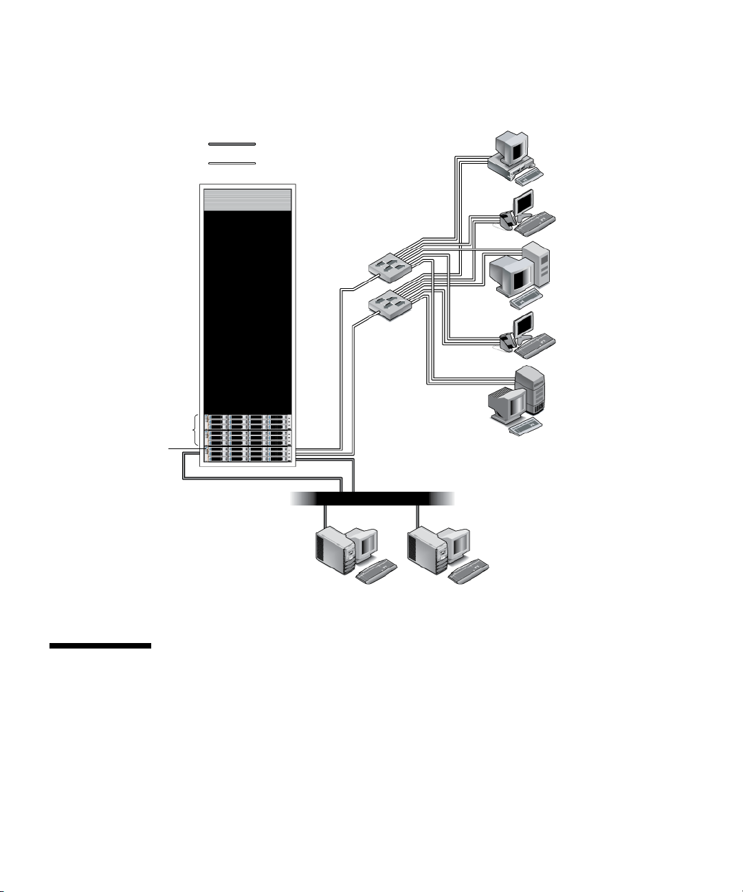
FIGURE 1-1 Sun StorageTek 2500 Series Array Product Overview
Data hosts
Expansion trays
Controller tray
Ethernet out-of-band
Redundant Fibre Channel
FC switch
FC switch
Host 1
Host 2
Host 3
Host 4
Host 5
Local
management host
Front-Access Components of the Trays
Components that are accessed through the front of the Sun StorageTek 2540 Array,
the Sun StorageTek 2530 Array, and the Sun StorageTek 2500 Array are identical in
appearance. The disk drives in your controller tray might differ in appearance from
those shown in FIGURE 1-2. The variation does not affect the function of the disk
drives.
2 Sun StorageTek 2500 Series Array Hardware Installation Guide • March 2007
Remote
management host
Page 19
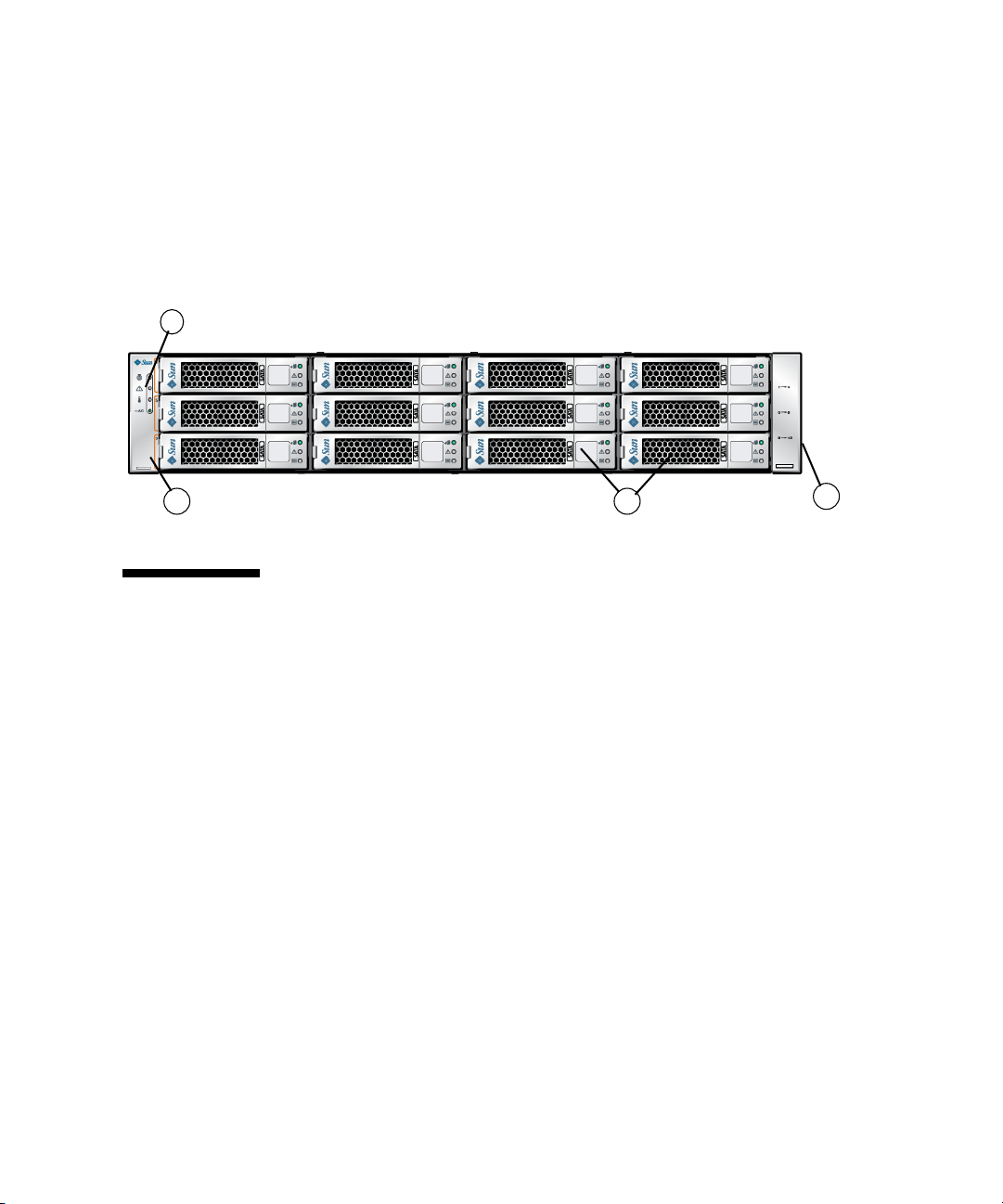
The front-access components include the following:
■ End caps – Plastic, removable caps on the right and left side of the tray. Numbers
on the side of the right end cap indicate the numbering of the drives.
■ LEDs (light emitting diodes) – Four LEDs located on the on the left-side end cap
■ Disk drives – Twelve removable disk drives
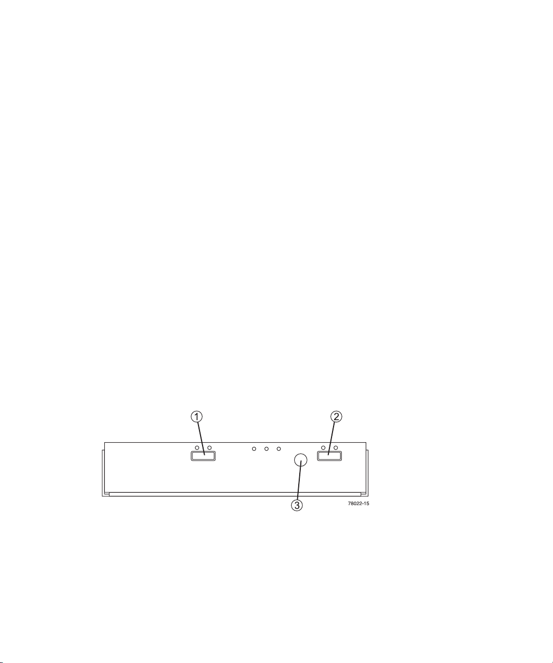
FIGURE 1-2 Tray Front-Access Components
3
1. End Caps
2. Disk Drives
3. Tray LEDs
1
2
1
LEDs on the Front of the Trays
The four LEDs on the front of the Sun StorageTek 2540 Array, the Sun StorageTek
2530 Array, and the Sun StorageTek 2501 Array are identical in appearance and
function. The LEDs are located on the left-side endcap of the tray.
Chapter 1 Tray Overviews 3
Page 20
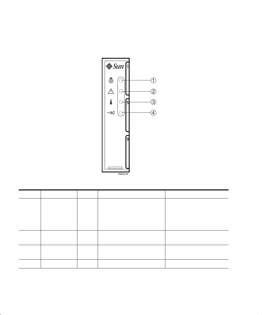
FIGURE 1-3 Location of the LEDs on the Front of the Trays
TABLE 1-1 Description of the LEDs on the Front of the Trays
Location LED Color On Off
1 Locate White Indicates a failed component on
Normal condition
this tray. The locate light is
turned on manually by CAM to
help you find the tray that
requires attention.
2 Service Action
Required (Fault)
3Over
Temperature
Amber A component within the tray
requires attention.
Amber The tray temperature has
reached an unsafe level.
The components in the tray are
operating normally.
The tray temperature is within
operational range.
4 Power Green Power is present. Power is not present.
4 Sun StorageTek 2500 Series Array Hardware Installation Guide • March 2007
Page 21
Rear-Access Components of the Trays
Components that are accessed from the rear of the Sun StorageTek 2540 Array and
the Sun StorageTek 2530 Array controller trays include:
■ Controller Modules – Two removable controller modules.
■ Power-fan assembly – Two removable power supply modules with cooling fans.
The power-fan assembly is identical and interchangeable to the power-fan
assemblies used for Sun StorageTek 2501 Array drive expansion tray.
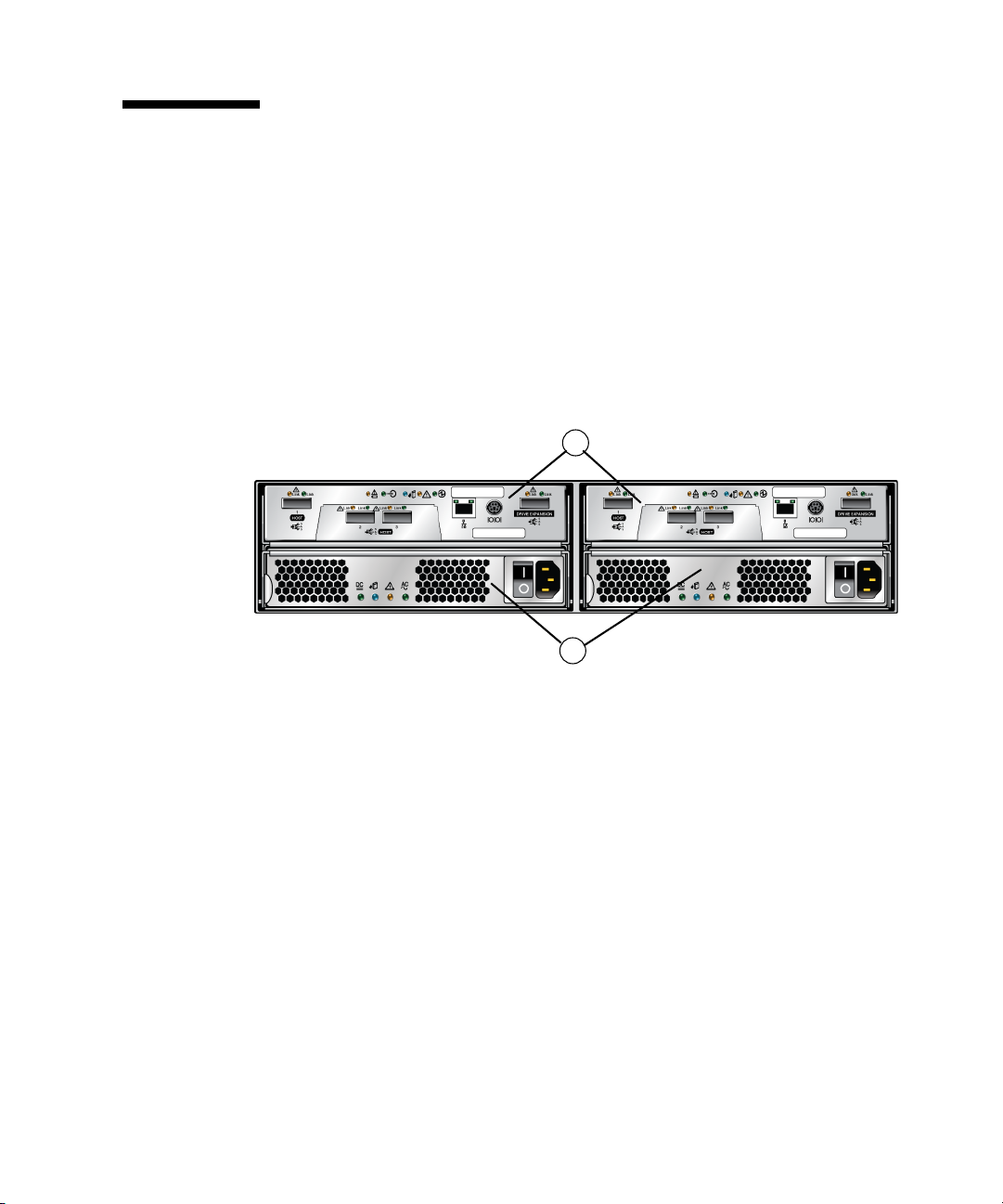
FIGURE 1-4 Controller Tray Rear-Access Components
1
1. Controller Modules
2
2. Power-Fan Assembly
Modules
Components that are accessed from the rear of the Sun StorageTek 2501 Array drive
expansion tray are:
■ I/O Modules (IOMs) – Two removable input/output modules
■ Power-fan assemblies – Two removable power supply modules with cooling
fans. The power-fan assembly is identical and interchangeable to the power-fan
assemblies used for Sun StorageTek 2540 Array and the Sun StorageTek 2540
Array.
Chapter 1 Tray Overviews 5
Page 22
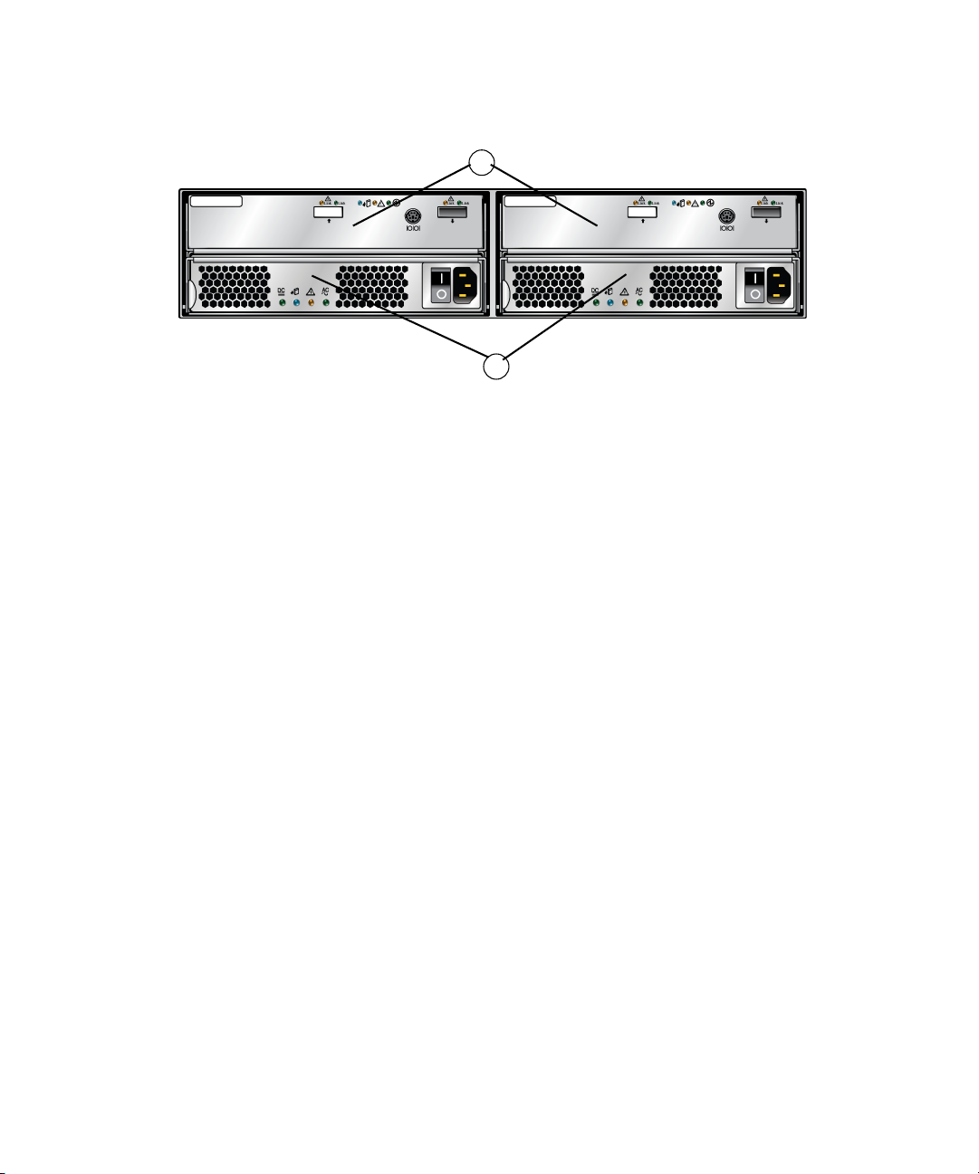
FIGURE 1-5 Drive Expansion Tray Rear-Access Components
1
1. IOM Modules
2
2. Power-Fan
Assembly Modules
Controllers
The Sun StorageTek 2540 Array and the Sun StorageTek 2530 Array have two
controllers. The controllers manage the input/output (I/O) between the volumes
and the data host. The controllers have an Ethernet connection to the management
host for out-of-band management and contain a battery that provides backup power
to the 1 GB DIMM cache memory for up to three days in the event of a power loss.
Because each controller tray contains two controllers, the data path through one
controller can fail and the other controller provides a redundant data path to all of
the disk drives. If a controller fails, you can replace the failed controller while the
power is applied and the storage array is processing data (a hot swap). The system
automatically updates the firmware for the new controller so that it matches the
configuration database.
Each controller has a media access control (MAC) address that identifies it on the
network. The MAC address for a controller is on a label on the controller. The MAC
address label is attached to the controller in two places: at the top of the tray and at
the rear of the tray.
The tray ID numbers are set by the trays themselves on first power on. However,
you can change the setting through the Common Array Manager software. The tray
ID numbers on both of the controllers in one controller tray are identical under
optimal operating conditions.
Sun StorageTek 2540 Array
This Fibre Channel (FC) controller tray provides the following capabilities:
6 Sun StorageTek 2500 Series Array Hardware Installation Guide • March 2007
Page 23
■ Two data host connectors per controller that can support either a fiber-optic
interface or a copper interface with 1, 2, or 4 Gb/s data host connection speed
■ One drive expansion tray Serial Attached SCSI (SAS) connector with 3 Gb/s drive
expansion tray connection speed
■ 512-MB or 1-GB mirrored cache
■ Maximum connection of 36 disk drives (one controller tray and two drive
expansion trays)
When fiber-optic cables are used to connect to the data host, a Small Form-factor
Pluggable (SFP) transceiver is required to make the connection.
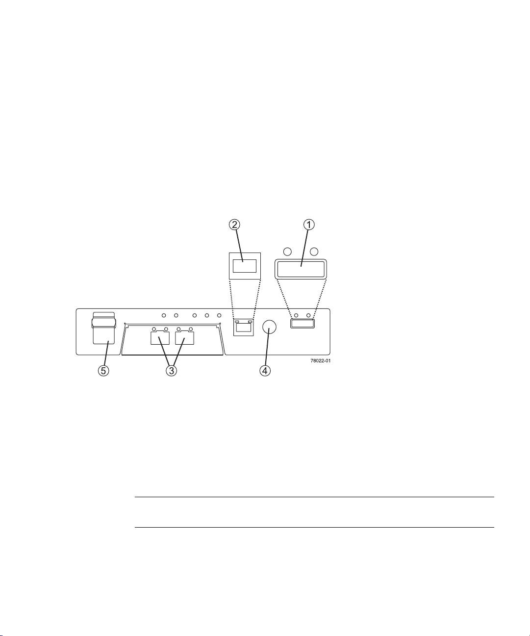
FIGURE 1-6 Sun StorageTek 2540 Array Connectors
1. Drive Expansion Tray Connector
(SAS Out)
2. Ethernet Management Host
Connector
3. Fibre Channel Data Host
Connectors or Copper Data Host
Connectors
4. RS-232 Connector (Diagnostics
Por t)
5. Not Used
SFP Transceivers
You can connect the Sun StorageTek 2540 Array to either copper host interface cables
or fiber-optic host interface cables. If you use fiber-optic cables, you must install an
SFP transceiver in each interface connector on the controller where a fiber-optic cable
is to be installed. The SFP transceiver is required to translate the optical signals from
the fiber-optic cable into digital signals for the controller.
Note – The SFP transceiver shown might look different from those that are shipped
with your controller tray. The difference does not affect transceiver performance.
Chapter 1 Tray Overviews 7
Page 24
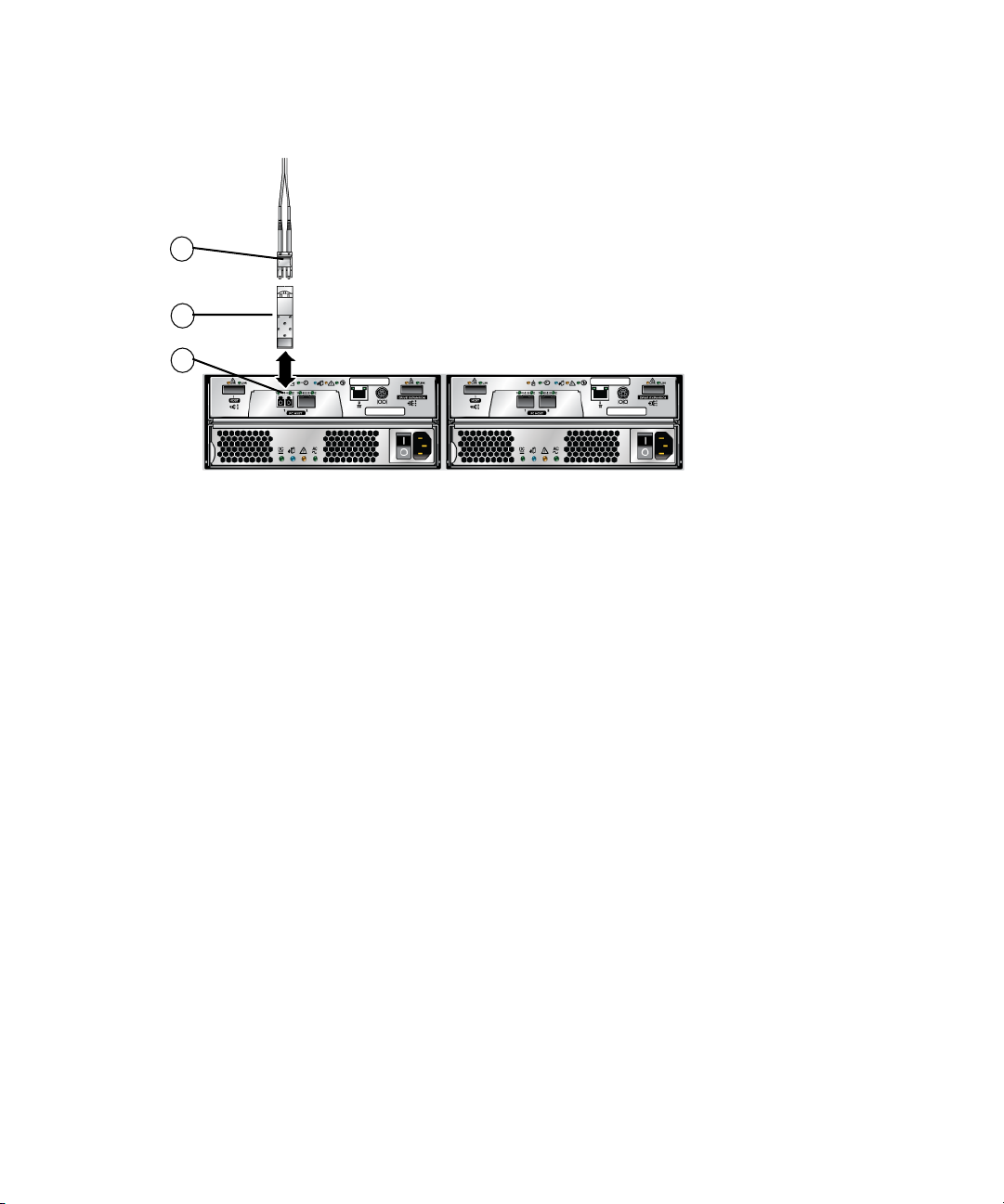
FIGURE 1-7 SFP Transceiver for the Sun StorageTek 2540 Array
1. Data Host Connector
2. SFP Transceiver
3
3. Fiber-Optic Cable
2
1
Sun StorageTek 2530 Array
This SAS controller tray provides the following capabilities:
■ Three SAS host connectors with 3 Gb/s host connection speed
■ One drive expansion tray SAS connector for the drive channel with 3 Gb/s drive
expansion tray connection speed
■ 512-MB or 1-GB mirrored cache
■ Maximum connection of 36 disk drives (one controller tray and two drive
expansion trays)
8 Sun StorageTek 2500 Series Array Hardware Installation Guide • March 2007
Page 25
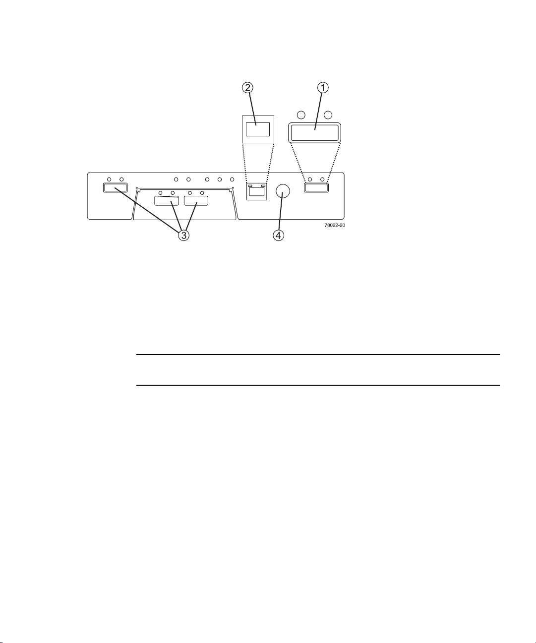
FIGURE 1-8 Sun StorageTek 2530 Array Controller Connectors
1. Drive Expansion Tray
Connector (SAS Out)
2. Ethernet Management Host
Connector
3. SAS Data Host Connectors
4. RS-232 Connector
(Diagnostics Port)
Controller Tray and Drive Expansion Tray PowerFan Assembly
The power-fan assembly for the Sun StorageTek 2540 Array, the Sun StorageTek 2530
Array, and the Sun StorageTek 2501 Array is identical and interchangeable.
Note – A minimum of two disk drives must be operating in a controller tray or a
drive expansion tray to avoid generating a power-fan assembly error.
The power-fan assembly contains an integrated cooling fan. The power supply
provides power to the internal components by converting incoming AC voltage to
DC voltage. The fan circulates air inside of the tray by pulling air in through the
vents on the front of the assembly and pushing the air out of the vents on the back
of each fan.
Each tray contains two power-fan assemblies. If one power supply is turned off or
malfunctions, the other power supply maintains electrical power to the tray.
Likewise, the fans provide redundant cooling. If one of the fans in either fan housing
fails, the remaining fan continues to provide sufficient cooling to operate the tray.
The remaining fan runs at a higher speed until the failed fan is replaced. Replace the
failed fan as soon as possible.
Chapter 1 Tray Overviews 9
Page 26
Sun StorageTek 2501 Array
The drive expansion tray expands the storage capacity of a storage array. The
controllers in the controller tray can connect to the drive expansion tray and access
the disk drives in the drive expansion tray for additional storage. A drive expansion
tray contains both physical components (disk drives, IOMs, and power-fan
assemblies) and logical components (virtual disks and volumes).
Drive Expansion Tray IOM
The drive expansion tray contains two IOMs that provide the interface between the
disk drives in the drive expansion tray and the controllers in the controller tray. The
IOM also monitors sub-system parameters. Each controller in the controller tray
connects to an IOM.
If one IOM fails, the other IOM provides a redundant data path to the disk drives.
You can replace a failed IOM while the power to the storage array is turned on and
the storage array is processing data (a hot swap).
Drive Expansion Tray IOM Connectors
The IOM connects to the controller tray and drive expansion trays with SAS cables.
Each IOM in a drive expansion tray has two SAS expansion connectors. One
connector shows an up arrow, and the other connector shows a down arrow.
FIGURE 1-9 SAS Connectors on the Drive Expansion Tray IOM
When connecting the SAS cable from an IOM in one drive expansion tray to an IOM
in another drive expansion tray, connect from a down arrow to an up arrow. If the
cable is plugged into two connectors with arrows of the same direction,
communication between the two drive expansion trays is lost.
10 Sun StorageTek 2500 Series Array Hardware Installation Guide • March 2007
1. SAS Connector (Up
Arrow)
2. SAS Connector
(Down Arrow)
3. Serial Connector
Page 27
LEDs on the Rear of the Trays
Controller LEDs on the Sun StorageTek 2540 Array
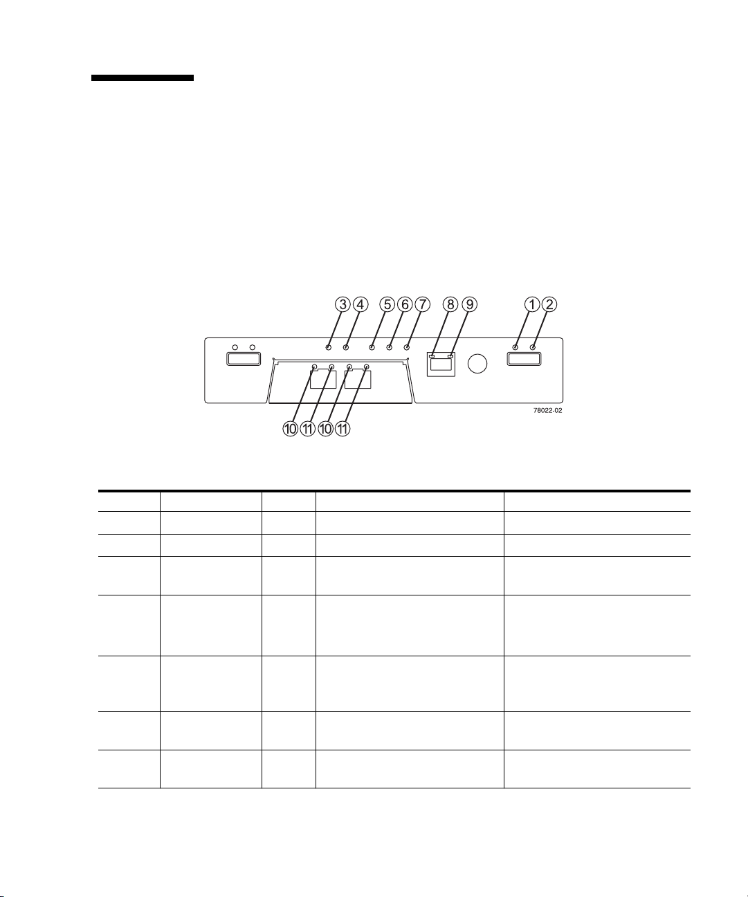
FIGURE 1-10 Locations of the Controller LEDs on the Sun StorageTek 2540 Array
TABLE 1-2 Descriptions of the Controller LEDs on the Sun StorageTek 2540 Array (1 of
Location LED Color On Off
1 Link Fault Amber At least one link has an error. Normal condition
2 Drive Link Green At least one link is active. At least one link has an error
3 Battery Fault Amber Indicates a fault within the
4 Cache Active Green Caching is enabled.
5 Service Action
Allowed
6 Service Action
Required (Fault)
7 Power Green Power is present. No power is applied to the
2)
battery backup unit.
When blinking, the cache has
data.
Blue The controller can be removed
from the controller tray.
Amber Indicates a fault within the
controller.
Normal condition
Indicates a problem if caching is
enabled.
The controller cannot be
removed from the controller
tray.
Normal condition
controller tray.
Chapter 1 Tray Overviews 11
Page 28
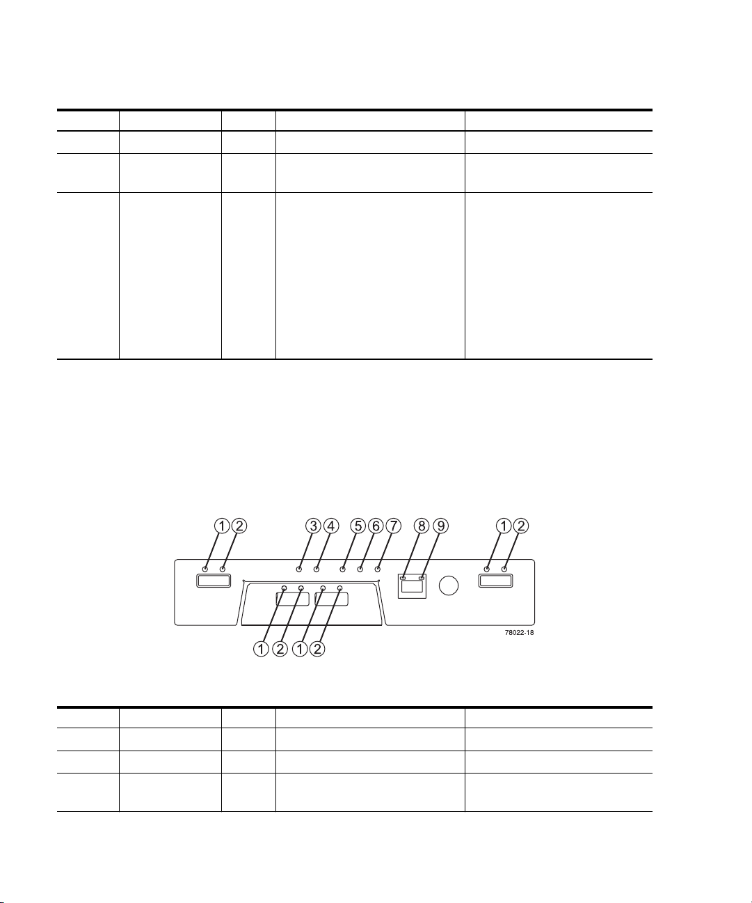
TABLE 1-2 Descriptions of the Controller LEDs on the Sun StorageTek 2540 Array (2 of
Location LED Color On Off
2)
8 Ethernet Link Green The connection is active. The connection is not active.
9 Ethernet
100BASE-TX
10 and 11 Host Link Green Both LEDs on indicate a 4-Gb/s
Green 100BASE-TX connection is
active.
data rate from the management
software host.
The 100BASE-TX connection is
not active.
Both LEDs off indicate no link
to the management software
host.
Left LED on and right LED off
indicate a 1-Gb/s data rate from
the management software host.
Right LED on and left LED off
indicate a 2-Gb/s data rate from
the management software host.
Controller LEDs on the Sun StorageTek 2530 Array
FIGURE 1-11 Locations of the Controller LEDs on the Sun StorageTek 2530 Array
TABLE 1-3 Descriptions of the Controller LEDs on the Sun StorageTek 2530 Array (1 of
Location LED Color On Off
2)
1 Link Green At least one link is active. All links have failed.
2 Link Fault Amber At least one link has an error. Normal condition.
3 Battery Fault Amber Indicates a fault within the
Normal condition.
battery backup unit.
12 Sun StorageTek 2500 Series Array Hardware Installation Guide • March 2007
Page 29

TABLE 1-3 Descriptions of the Controller LEDs on the Sun StorageTek 2530 Array (2 of
Location LED Color On Off
4 Cache Active Green Caching is enabled.
5 Service Action
Allowed
6 Service Action
Required (Fault)
7 Power Green Power is present. No power is applied to the
8 Ethernet Link Green The connection is active. The connection is not active.
9 Ethernet
100BASE-TX
2)
When blinking, the cache has
data.
Blue The controller can be removed
from the controller tray.
Amber Indicates a fault within the
controller.
Green 100BASE-TX connection is
active.
Indicates a problem if caching is
enabled.
The controller cannot be
removed from the controller
tray.
Normal condition
controller tray.
The 100BASE-TX connection is
not active.
Controller Tray and Drive Expansion Tray PowerFan Assembly LEDs
The power-fan assembly LEDs for the Sun StorageTek 2540 Array, the Sun
StorageTek 2530 Array, and the Sun StorageTek 2501 Array are identical.
Chapter 1 Tray Overviews 13
Page 30
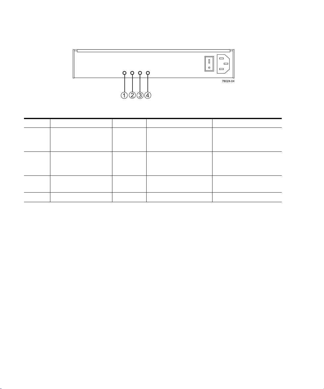
FIGURE 1-12 Locations of the Power-Fan Assembly LEDs
TABLE 1-4 Descriptions of the Power-Fan Assembly LEDs
Location LED Color On Off
1 DC Power (DC Good) Green DC power from the
power-fan assembly is
available.
2 Service Action Allowed Blue The power-fan assembly
can be removed from the
tray.
3 Fault Amber A fault exists within the
DC power from the powerfan assembly is not
available.
The power-fan assembly
cannot be removed from the
tray.
Normal condition
power-fan assembly.
4 Power (AC Good) Green Power is present Power is not present
14 Sun StorageTek 2500 Series Array Hardware Installation Guide • March 2007
Page 31

IOM LEDs on the Sun StorageTek 2501 Array
FIGURE 1-13 Locations of the IOM LEDs
TABLE 1-5 Descriptions of the IOM LEDs
Location LED Color On Off
1 IOMLink Fault Amber A link error occurred. No errors have occurred.
2 IOM Link Green The link is active. A link error occurred.
Service Action
3
4
5
Allowed
Service Action
Required
(Fault)
Power Green Power is present in the drive
Blue The IOM can be removed
Amber A fault exists within the IOM. Normal condition
Service Action LEDs
Each controller, power-fan assembly, IOM, and disk drive has a Service Action
Allowed LED. The Service Action Allowed LED indicates when you can remove a
component safely. See the “LEDs on the Rear of the Trays” section on page 1-11 for
the locations and descriptions of the Service Action Allowed LEDs on a controller
tray and a drive expansion tray, and see “LEDs on the Disk Drives” on page 1-18 for
disk drive Service Allowed LEDs.
from the drive expansion tray.
expansion tray.
The IOM cannot be
removed from the drive
expansion tray.
No power is applied to the
drive expansion tray.
Chapter 1 Tray Overviews 15
Page 32

Caution – Potential loss of data access – Never remove a power-fan assembly, a
controller module, or a disk drive unless the Service Action Allowed LED is turned
on or you are given specific instructions to do so by the Common Array Manager
software Service Advisor.
If a module fails and must be replaced, the Service Action Required LED on that
module turns on to indicate that a service action is required. The Service Action
Allowed LED also will turn on if it is safe to remove the module. If there are data
availability dependencies or other conditions that dictate that a module should not
be removed, the Service Action Allowed LED remains off.
The Service Action Allowed LED automatically turns on or turns off as conditions
change. In most cases, the Service Action Allowed LED turns on when the Service
Action Required (Fault) LED is turned on for a module.
Note – If the Service Action Required (Fault) LED is turned on but the Service
Action Allowed LED is turned off for a particular module, you might have to service
another component first. Check the Common Array Manager software Service
Advisor to determine the action you should take.
Disk Drives
Disk drives for the Sun StorageTek 2500 Series Array have three components: a hard
drive, a hard drive carrier, and an adapter card for connecting the disk drive to the
midplane. The disk drives can be Serial Advance Technology Attachment (SATA)
disk drives, Fibre Channel (FC) disk drives, or SAS disk drives.
Controller trays or drive expansion trays hold up to 12 disk drives, for a maximum
of 36 disk drives in a storage array. To reach the maximum of 36 disk drives, the
storage array must consist of one controller tray and two drive expansion trays.
Access to disk drives is from the front of the tray.
Refer to the storage array release notes for supported drives.
Note – The disk drives in your tray might differ in appearance from those shown
here. The variation does not affect their function.
16 Sun StorageTek 2500 Series Array Hardware Installation Guide • March 2007
Page 33

FIGURE 1-14 Disk Drives
The physical locations of the disk drives are numbered 1 through 12, from left to
right, and from top to bottom. The right end cap has numbers on the side showing
the numbers of the adjacent drives. The Common Array Manager Service Advisor
software automatically detects a disk drive’s tray ID and slot designation.
Chapter 1 Tray Overviews 17
Page 34

LEDs on the Disk Drives
FIGURE 1-15 Locations of the Disk Drive LEDs
TABLE 1-6 Descriptions of the Disk Drive LEDs
1
2
3
Location LED Color General Behavior
Service Action
1
2
3
18 Sun StorageTek 2500 Series Array Hardware Installation Guide • March 2007
Allowed
Fault Amber On – The disk drive has a problem.
Power Green Off – The power is turned off.
Blue On – The disk drive can be removed from the tray.
Off – The disk drive cannot be removed from the
tray.
Off – Normal condition.
On – The power is on and the disk drive is
operating normally.
On and blinking (0.5 s on, 0.5 s off) –Disk drive
I/O activity is taking place.
Page 35

TABLE 1-7 Disk Drive States Represented by the LEDs
Disk Drive State
Power is not applied. Off Off
Normal operation, power is turned on, no disk drive I/O activity is
occurring.
Normal operation, disk drive I/O activity is occurring. On, blinking Off
Service action required, a fault condition exists, and the disk drive is
offline.
Power
(Green LED)
On, solid Off
On, solid On, solid
Common Array Manager Software
The Sun StorageTek 2500 Series Array is managed by the Sun StorageTek Common
Array Manager software. The Common Array Manager provides web browser–
based management and configuration from an external management host, data host
software that controls the data path between the data host and the array, and a
remote command-line interface (CLI) client that provides the same control and
monitoring capability as the web browser, and is scriptable for running frequently
performed tasks.
Fault
(Amber
LED)
The Common Array Manager software includes Service Advisor, an online reference
full of hardware and software configuration and troubleshooting information and
procedures.
For information about installing the Common Array Manager software and
configuring and managing the array, see the Sun StorageTek Common Array Manager
Software Installation Guide.
Service Advisor and CustomerReplaceable Units
Customer-replaceable units (CRUs) are designed to be replaceable by customers.
Chapter 1 Tray Overviews 19
Page 36

To see a list of the hardware components that can be replaced at the customer site
refer to Service Advisor in the Sun StorageTek Common Array Manager software.
The Service Advisor also provides information and procedures for replacing array
components.
Overview of the Installation Process
Before you begin to install the array, you must do the following:
■ Read the Sun StorageTek 2500 Series Array Release Notes for any late-breaking
information related to the installation of the array.
■ Prepare the site as described in these books:
■ Sun StorageTek 2500 Series Array Regulatory and Safety Compliance Manual
■ Sun StorageTek 2500 Series Array Site Preparation Guide
The following checklist (
TABLE 1-8) outlines all of the tasks required for installing the
Sun StorageTek 2500 Array hardware and tells you where you can find detailed
procedures. To ensure a successful installation, perform the tasks in the order in
which they are presented.
TABLE 1-8 Sun StorageTek 2500 Series Array Hardware Installation Checklist
Step Installation Task Where to Find Procedure
1. Unpack the cabinet and move it into
position.
2. Install and secure the cabinet. • Sun StorageTek Expansion Cabinet Installation
3. Unpack the rackmounting kit and
check its contents.
4. Unpack the tray box and check its
contents.
5. Prepare the cabinet for installation. “Preparing the Cabinet” on page 26
6. Attach the rails to the cabinet. “Attaching the Rails to a Cabinet” on page 27
7. Mount the controller tray and
expansion trays in the cabinet.
8. Attach the power cables. “Connecting the Power Cables” on page 42
9. Cable the controller tray and
expansion trays.
Unpacking guide attached to the outside of
the shipping carton
and Service Manual
• Sun Rack Installation Guide
“Preparing the Universal Rail Kit” on page 24
“Preparing the Tray” on page 25
“Installing a Tray in a Cabinet” on page 37
“Intertray Cabling” on page 42
20 Sun StorageTek 2500 Series Array Hardware Installation Guide • March 2007
Page 37

TABLE 1-8 Sun StorageTek 2500 Series Array Hardware Installation Checklist
Step Installation Task Where to Find Procedure
10. Connect the management host. “Connecting the Management Host” on
page 49
11. Attach the host interface cables. “Connecting Data Hosts to the 2540 Array” on
page 51
12. Turn on the power. “Powering On the Array” on page 62
When the tasks in TABLE 1-8 are complete, you can install the Common Array
Manager software on an external management host, install and upgrade firmware
from the management host, and perform initial array setup and system
configuration. See the Sun StorageTek Common Array Manager Software Installation
Guide for complete information on software-related tasks.
Chapter 1 Tray Overviews 21
Page 38

22 Sun StorageTek 2500 Series Array Hardware Installation Guide • March 2007
Page 39

CHAPTER
2
Installing Trays
Use the procedures in this chapter to install trays in a cabinet. The number of trays
you need to install depends on your overall storage requirements. You can install a
maximum of three trays, one controller tray and up to two expansion trays for each
array.
This chapter describes the process of installing the Sun StorageTek 2500 Series Array.
It contains the following sections:
■ “Preparing for the Installation” on page 24
■ “Attaching the Rails to a Cabinet” on page 27
■ “Installing a Tray in a Cabinet” on page 37
■ “Connecting the Power Cables” on page 42
■ “Intertray Cabling” on page 42
■ “Drive Module Cable Labeling” on page 47
■ “Next Steps” on page 48
The installation procedures in this chapter require the following items:
■ #2 Phillips screwdriver (minimum 4-inch length recommended)
■ #3 Phillips screwdriver (minimum 4-inch length recommended)
■ Antistatic protection
Caution – Electrostatic discharge can damage sensitive components. Touching the
array or its components without using a proper ground might damage the
equipment. To avoid damage, use proper antistatic protection before handling any
components.
23
Page 40

Preparing for the Installation
Use the following procedures to prepare for installation:
■ “Preparing the Universal Rail Kit” on page 24
■ “Preparing the Tray” on page 25
■ “Preparing the Cabinet” on page 26
Preparing the Universal Rail Kit
Use the universal rail kit to mount the Sun StorageTek 2500 Series Array trays in any
of the following cabinets:
■ Any standard Sun cabinet, such as the Sun Rack 900/1000 cabinet
■ Any 19-inch wide, 4-post, EIA-compatible rack or cabinet with a front-to-back
depth between vertical cabinet rails of 24-36 inches (with threaded or unthreaded
cabinet rails).
■ The Sun StorageTek Expansion cabinet
Unpacking the Universal Rail Kit
Unpack the universal rail kit and check the contents.
The universal rail kit (part number 594-2489-02) comes with pre-assembled rails and
contains the following items:
■ Left rail assembly
■ Right rail assembly
■ 10 8-32x3/8” panhead screws with lockwashers
■ 4 M4 flathead screws
■ 4 cabinet rail adapter plates (used for unthreaded cabinet rails only)
Loosening the Rail Adjustment Screws
To loosen the adjustment screws on the left and right rails:
Use a flathead screwdriver to loosen the two rail adjustment screws on each rail to
allow adjustment of each rail length (
24 Sun StorageTek 2500 Series Array Hardware Installation Guide • March 2007
FIGURE 2-1).
Page 41

FIGURE 2-1 Loosening the Rail Screws to Adjust the Rail Length
Note – The rails are preconfigured to adjust to cabinet rail depths of between 24
inches (609.6 mm) and 34 inches (863.6 mm).
Preparing the Tray
Caution – Two people are needed to lift and move the tray. Use care to avoid injury.
A traycan weigh up to 54.3 pounds (24.6 kg).
1. Unpack the tray.
2. Check the contents of the box for the following items:
■ Sun StorageTek 2500 Series Arraytrays (controller or expansion)
■ Ship kit for the controller tray
■ One pair left and right end caps (plastic bezels)
■ Four 4 Gbps FC SFPs (2 per FC Controller module)
Chapter 2 Installing Trays 25
Page 42

■ Two 6-meter RJ45 -RJ45 Ethernet cables (one per controller module)
■ One RJ45-DIN9 cable
■ One RJ45-DB9 adapter
■ Sun StorageTek Common Array Manager Software CD
■ Sun StorageTek Common Array Manager Software Installation Guide (on the
software CD)
■ Common Array Manager sscs CLI Quick Reference Card
■ Sun StorageTek 2500 Series Array Hardware Installation Guide (Hardcopy)
■ Accessing Documentation guide
■ Premium feature license cards (ordered optionally)
■ Ship kit for each expansion tray
■ Two 1-meter copper SAS cables (one per I/O module)
■ Accessing Documentation guide
AC power cords are shipped separately with each tray.
Preparing the Cabinet
Select the cabinet in which you will be installing the array. Be sure the cabinet is
installed as described in the installation instructions provided with it.
1. Stabilize the cabinet as described in the cabinet documentation.
2. If the cabinet has casters, make sure the casters are locked to prevent the
cabinet from rolling.
3. Remove or open the front panel.
4. Remove or open the vented back panel.
Planning the Order of the Tray Installation
Install the trays starting with the controller tray at the lowest available 2RU tray slot
in the cabinet. Next, install the expansion trays for the first controller tray. If room
remains in the cabinet, repeat for the next controller and expansion trays.
Starting at the bottom distributes the weight correctly in the cabinet.
26 Sun StorageTek 2500 Series Array Hardware Installation Guide • March 2007
Page 43

Attaching the Rails to a Cabinet
Depending on the type of cabinetin which you will install the tray, use one of the
following procedures to attach the rails:
■ “Attaching the Universal Rail Kit to a Standard Sun or 19-Inch Cabinet With
Threaded Cabinet Rails” on page 27
■ “Attaching the Universal Rail Kit to a Standard 19-Inch Cabinet With Unthreaded
Cabinet Rails” on page 31
Each tray requires two standard mounting rack units (2RU) of vertical space in the
cabinet. Each standard mounting rack unit (RU) has three mounting holes in the left
and right cabinet rails. The top mounting hole of the lower RU is always closest to
the bottom mounting hole of the upper RU, hence the divsion between RUs on a
cabinet rail is between the two closeest mounting holes in a grouping.
The universal rails have an adjustable depth of 24” to 34”.
Attaching the Universal Rail Kit to a Standard Sun or 19-Inch Cabinet With Threaded Cabinet Rails
This procedure describes the steps to attach the universal rail kit to:
■ All standard Sun cabinets, including the Sun Rack 900/1000 cabinets
■ Sun StorageTek Expansion cabinets
■ All 19-inch wide, 4-post EIA-compatible racks and cabinets with the following
cabinet rail types:
■ M5 threaded
■ M6 threaded
■ 10-32 threaded
■ 12-24 threaded
■ circular unthreaded
1. To attach the universal rail kit to a cabinet withthese cabinet rail typesPosition
the front flange of the left universal rail behind the left front cabinet rail
(
FIGURE 2-2).
Chapter 2 Installing Trays 27
Page 44

Note – The RUs are not labeled on all racks, as they are on the Sun cabinets. The
rule of thumb to remember is that the division of RUs passes between the two
closest rail holes in each set of holes (see FIGURE 2-2).
FIGURE 2-2 Positioning the Front of the Left Rail Behind the Left Front Cabinet Rail
2. Insert the 8-32 screws through the center holes in each RU of the rack into the
top and bottom holes in the Universal rail (
FIGURE 2-3).
These screws pass through the cabinet rail holes and screw into threaded holes in
the Universal rail.
28 Sun StorageTek 2500 Series Array Hardware Installation Guide • March 2007
Page 45

FIGURE 2-3 Securing the Left Rail to the Front of the Cabinet
3. Repeat Step 1 and Step 2 for the right rail.
4. At the back of the cabinet, adjust the length of the left rail as needed to fit the
cabinet, and position the rail flange behind the face of the cabinet rail
(
FIGURE 2-4).
Chapter 2 Installing Trays 29
Page 46

FIGURE 2-4 Adjusting the Length of the Left Rail at the Back of the Cabinet
5. Align the rail flange so that the top and bottom mounting holes match the
center holes in the RUs corresponding to those used on the front of the cabinet.
30 Sun StorageTek 2500 Series Array Hardware Installation Guide • March 2007
Page 47

6. Insert the 8-32 screws through the center holes of the rack into the top and
bottom mounting holes on the universal rail (
FIGURE 2-5 Securing the Left Rail to the Back of the Cabinet
FIGURE 2-5).
7. Repeat Step 4, Step 5, and Step 6 for the right rail.
Attaching the Universal Rail Kit to a Standard 19-Inch Cabinet With Unthreaded Cabinet Rails
This procedure describes the steps to attach the universal rail kit to:
Chapter 2 Installing Trays 31
Page 48

■ All 19-inch wide, 4-post EIA-compatible racks and cabinets with unthreaded
cabinet rails (square hole racks).
To attach the universal rail kit to a cabinet with unthreaded cabinet rails, follow
these steps first for the left rail and then for the right rail:
1. Hook a cabinet rail adapter plate over the front of the cabinet rail. (
FIGURE 2-6 Inserting the Cabinet Rail Adapter Plate on the Cabinet Rail
FIGURE 2-6)
Position the adapter plate over of the 2RU slot in which the tray is to be
mounted. The hook on the top of the adapter plate hooks into the top hole of the
upper RU. The flat flange on the bottom of the adapter plate fits into the bottom
hole of the lower RU (
32 Sun StorageTek 2500 Series Array Hardware Installation Guide • March 2007
FIGURE 2-7).
Page 49

FIGURE 2-7 Adapter plate in place on the Cabinet Rail.
2. Slide the front flange of the universal rail between the front cabinet rail and
the top hook of the rail adater plate (
FIGURE 2-8).
Chapter 2 Installing Trays 33
Page 50

FIGURE 2-8 Slide the flange of the rail behind the cabinet rail and between that and the
hook of the rail adapter plat.e, as shown.
3. Insert and tighten two 8-32 screws through the top and bottom holes in the
adapter plate, through the cabinet rail, and into the top and bottom threaded
holes in the universal rail mounting flange (
FIGURE 2-9).
34 Sun StorageTek 2500 Series Array Hardware Installation Guide • March 2007
Page 51

FIGURE 2-9 Securing the Rail to the Front left of the Cabinet
4. Repeat Step 1 through Step 3 on the corresponding cabinet rail at the back of
the cabinet (
FIGURE 2-10).
Mounting the rail on the back of the cabinet is the same as mounting it to the
front, after you extend the rail the necessary length to reach the rear cabinet rail.
Chapter 2 Installing Trays 35
Page 52

FIGURE 2-10 Adjusting the Length of the Rail at the Back of the Cabinet
5. Insert and tighten two 8-32 screws through the top and bottom holes in the
adpater plate, back cabinet rail, and universal rail mounting flange
(
FIGURE 2-11).
The screws passes through the unthreaded holes of the adapter plate and cabinet
rail mounting rail and screw into the threaded holes of the rail mounting flange.
36 Sun StorageTek 2500 Series Array Hardware Installation Guide • March 2007
Page 53

FIGURE 2-11 Securing the Rail to the Back of the Cabinet
For extra stability, you can tighten the rail screws as in FIGURE 2-1.
6. Repeat Step 1 through Step 5 to install the right rail.
Installing a Tray in a Cabinet
Install the controller tray in the first empty 2RU slot at the bottom of the cabinet. If
you are installing expansion trays, continue installing the trays from the bottom up.
1. Using two people, one at each side of the tray, carefully lift and rest the tray on
the bottom ledge of the left and right rails (
Caution – Use care to avoid injury. A tray can weigh up to 55 pounds (25 kg).
FIGURE 2-12).
Chapter 2 Installing Trays 37
Page 54
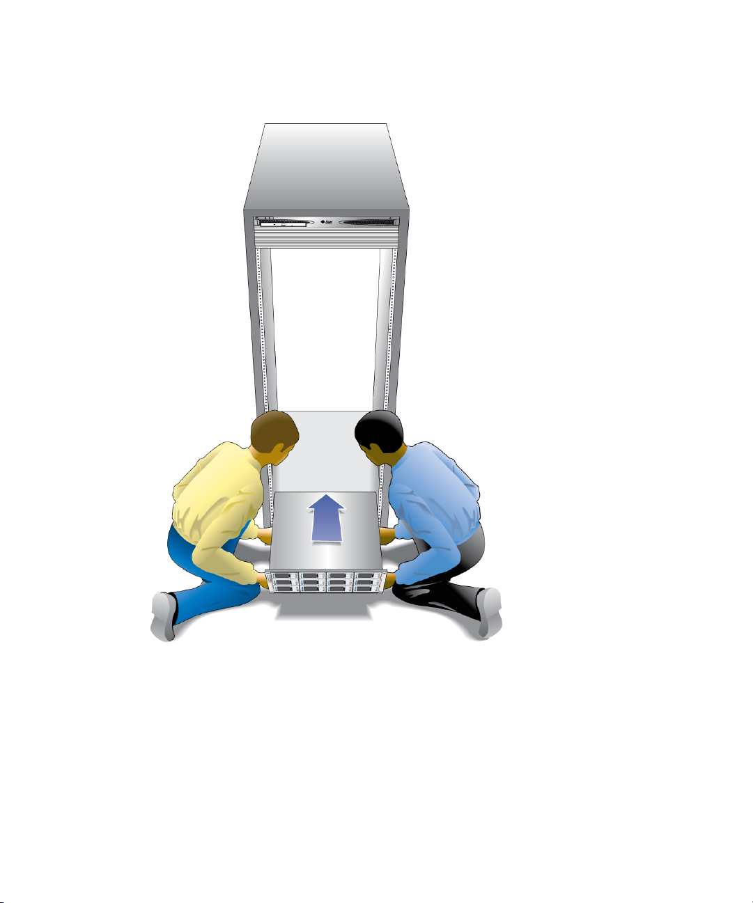
FIGURE 2-12 Positioning the Tray in the Cabinet
2. Carefully slide the tray into the cabinet until the front mounting flanges on the
tray touch the vertical face of the cabinet (
38 Sun StorageTek 2500 Series Array Hardware Installation Guide • March 2007
FIGURE 2-13).
Page 55

FIGURE 2-13 Array Controller Tray Installed
The tray has mounting flanges on both sides with three mounting holes in them. The
top and bottom holes are large enough to fit over the heads of the screws already in
the cabinet rails used to mount the universal rails. If the tray was shipped with end
caps (bezels) clipped on the tray mounting flanges, remove them before sliding the
tray all the way in over the mounting screw heads.
To remove an end cap , place your thumb on the lower front face of the cap and
reach your forefinger underneath to the back bottom edge of the cap, then pull
the cap towards you and slightly upwards.
On the rear of the array tray, a flat metal tab on each side corner slides into a special
mounting clip on the rear of each universal rail, securing the back of the array tray.
This makes the use of rear mounting screws to secure the tray in the rail
unnecessary, especially in locations where the rack and trays are not likely to be
moved. For racks that will be moved or shipped, Sun recommends that you install
M4 screws through the hole in the tab and into the corresponding threaded hole in
the rail as shown in
FIGURE 2-14.
Chapter 2 Installing Trays 39
Page 56

FIGURE 2-14 Rail clip and rear mounting hole on rear of array tray.
3. Insert a single 8-32 pan head screw through the center hole in each front
mounting flange and tighten (
40 Sun StorageTek 2500 Series Array Hardware Installation Guide • March 2007
FIGURE 2-15).
Page 57

FIGURE 2-15 Securing the Tray to the Front of a Sun Rack 900/1000 Cabinet
4. Replace the end caps (bezels) that cover the mounting flanges on the front of
the array tray.
On each front mounting flange, there is a small tab over which the end caps fit.
The end caps have a slot on top for this tab.
a. Place the end cap over the tab so the tab can go into the slot.
b. Snap the bottom of the end cap into place.
Chapter 2 Installing Trays 41
Page 58

Connecting the Power Cables
1. Verify that both power switches are turned off.
2. Verify that the circuit breakers in the cabinet are turned off.
3. Connect each power supply in the tray to a separate power source in the
cabinet.
4. Connect the primary power cables from the cabinet to the external power
source.
Note – Do not power on the array until you complete the procedures in this chapter.
The power-on sequence is described in detail in Chapter 4.
Intertray Cabling
This section describes how to cable a controller tray to expansion trays for several
different configurations. Each controller has one expansion port (
Controller A controls drive channel 1 through the A-side drive modules; Controller
B controls drive channel 2 through the B-side modules. Each drive channel provides
a separate path for data transfer from the controller tray to the expansion trays; the
two channels provide redundancy.
FIGURE 2-16).
FIGURE 2-16 Expansion Ports on the Controller Tray
SAS Expansion Ports to the Expansion Tray
Link Link
1
HOST
S
A
S
LinkLink LinkLink
23
S
A
HOST
S
Link Link
DRIVE EXPANSION
S
A
S
Link Link
1
HOST
S
A
S
Each expansion tray has two SAS port connectors, one marked with an up arrow
and the other marked with a down arrow (
FIGURE 2-17). You use SAS cables to
connect expansion trays to controllers.
42 Sun StorageTek 2500 Series Array Hardware Installation Guide • March 2007
LinkLink LinkLink
23
S
A
HOST
S
Link Link
DRIVE EXPANSION
S
A
S
Page 59

Note – Perform all SAS connections from an Out (down arrow) port to an In (up
arrow) port. If the cable is connected to two connectors with the same arrows,
communication between the two drive modules will be lost.
FIGURE 2-17 Expansion Ports on an Expansion Tray
1
2222
1
1. SAS Expansion In Port
2.SAS Expansion Out Port
22
2
2
Array Configuration Naming Convention
The configuration naming convention is “controllers x trays” where the first number
is the controller tray and the second is the sum of the controller tray and the number
of expansion trays. For example, 1x1 is a standalone controller tray, 1x2 is the
controller tray and one expansion tray, 1x is the controller tray and 2expansion trays
(
TABLE 2-1).
TABLE 2-1 Controller and Expansion Tray Configurations
Configuration
Identifier Controller Tray
Number of Expansion
Tra ys
1x1 1 0
1x2 1 1
1x3 1 2
Note – Do not add more expansion trays than the array supports.
Use the following instructions to connect the dual-RAID controller tray to one or
more expansion trays.
Chapter 2 Installing Trays 43
Page 60

Connecting Expansion Trays
Keep the following points in mind when adding expansion trays to your storage
array:
■ Expansion trays must be added with power to the array and I/O data transfer
turned off. If you need to add an expansion tray to an array that cannot be taken
off-line, contact your Sun Technical Support representative before attempting to
connect the new tray.
■ Controller and expansion trays are shipped with protective plastic plugs in the
SAS expansion ports. You must remove these before connecting cables.
■ Expansion trays are added serially, in a chain (actually two chains: channel one
through the A-side controller and modules, and channel two through the B-side
controller and modules). The SAS cable from the expansion port on a controller
connects to the In port (Up arrow) on an expansion tray drive module. The SAS
cable from a drive module on expansion tray 1 to a corresponding drive module
on expansion tray 2 connects from the Out port on expansion tray 1 to the
corresponding In port on expansion tray 2. This pattern repeats for each
additional drive module on a channel. See
reverse cabling pattern.
■ To connect cables for maximum redundancy, controller B must be cabled to the
expansion tray B-side modules in the opposite order as the expansion tray A-side
modules. That means the last drive module in the A-side chain from controller A
must be the first drive module in the B-side chain from controller B. See
FIGURE 2-19 for an illustration of cabling for maximum tray level redundancy.
■ On all SAS cables, affix a label to each end of the cable. See “Drive Module Cable
Labeling” on page 47 for labeling tips.
FIGURE 2-19 for an illustration of this
44 Sun StorageTek 2500 Series Array Hardware Installation Guide • March 2007
Page 61

Cabling an Expansion Tray to a Controller Tray
A Controller tray has two expansion ports, one on the Controller A module and one
on the Controller B module. To connect an expansion tray, connect an SAS cable
from each expansion port on the controller to each In port on the expansion tray.
FIGURE 2-18 shows a 1x2 array configuration consisting of one controller tray and one
expansion tray. Two SAS cables are required.
FIGURE 2-18 1x2 Array Configuration Cabling Example
To cable a 1x2 array configuration:
Expansion Tray
Controller Tray
A
1. Locate the Controller A and Controller B expansion ports at the back of the
controller tray (
2. Locate the In and Out expansion ports at the A-side and B-side back of the
expansion tray (
3. Connect one SAS cable between the Controller A expansion port and the Aside In port on the expansion tray (
4. Connect one SAS cable between the Controller B expansion port and the Bside In port on the expansion tray (
FIGURE 2-16).
FIGURE 2-17).
FIGURE 2-18).
FIGURE 2-18).
B
Cabling an Expansion Tray to Another Expansion Tray
Each additional expansion tray is added to the preceding expansion tray by
connecting SAS cables from the Out ports of the first tray to the In ports of the next
tray.
FIGURE 2-19 illustrates a 1x3 array configuration consisting of one controller tray
Chapter 2 Installing Trays 45
Page 62

and two expansion trays. The cable connections on the B-side are reversed (the cable
from the controller A expansion port goes to the In port of expansion tray 1; the
cable from the controller B expansion port goes to the In port on expansion tray 2)
for maximum redundancy. This pattern continues for each additional tray you add.
Two more SAS cables are required for each additional tray.
FIGURE 2-19 1x3 Array Configuration Cabling
To cable a 1x3 array configuration for maximum redundancy:
Expansion Tray 2
Expansion Tray 1
AB
1. Locate the Controller A and Controller B expansion ports at the back of the
controller tray (
FIGURE 2-16).
2. Locate In and Out expansion ports at the A-side and B-side back of the
expansion tray (
FIGURE 2-17).
3. Connect one SAS cable between the Controller A expansion port and the Aside expansion In port of expansion tray 1 (
FIGURE 2-19).
4. Connect one SAS cable between the Controller B expansion Out port and the
B-side expansion In port of expansion tray 2 (
5. Connect one SAS cable between the expansion tray 1 Out port and the A-side
expansion In port of expansion tray 2 (
46 Sun StorageTek 2500 Series Array Hardware Installation Guide • March 2007
FIGURE 2-19).
Controller Tray
FIGURE 2-19).
Page 63

6. Connect one SAS cable between the expansion tray 2 B-side Out port and the
B-side In port of expansion tray 2 (
FIGURE 2-19).
Drive Module Cable Labeling
Labels for the drive cables identify which controller ports and which expansion
connections in an expansion tray you use when you attach cables between a
controller and the drive modules on an expansion tray. Cable labels are useful if you
need to disconnect cables to service a controller. Attach a label to each end of the
cable. Use this design to create labels for drive cables:
■ Controller ID (for example, Controller A)
■ Expansion tray ID (for example, Tray A)
■ Expansion port ID (for example, In or Out)
■ Drive module ID
Example Label Abbreviation
In this example, the storage configuration has the following characteristics:
■ Drive channel 1
■ Controller A, drive channel 1
■ Drive module 1
■ Expansion Tray A (which is the left drive module), Out port
Using this design, the label includes the following information:
CtA-Dch1, Dm1-Tray_A (left), Out
Simplex Configurations
A simplex configuration is a 2530 Array with a single controller and a single
backend channel. By definition, there is a single path SAS connection to the data
host, and no redundancy is available. There can be expansion modules on the single
backend channel.
Chapter 2 Installing Trays 47
Page 64

Simplex cabling is the same as the cabling on a single channel of an ordinary array,
such as that shown on the A-side in
procedures in a simplex configuration are the same as those for a duplex
configuration with a failed controller (with the exception of the service procedures
targeted at the failed controller). These procedures are available in Service Advisor.
Maintenance procedures such as firmware updates or servicing of the controller or
expansion modules will cause loss of access to the array during the performing of
the procedure, since there is no backup channel.
Performance and default behavior are the same as a duplex configuration with a
failed or missing controller. Write cache is by nature in write-through mode because
there is no cache mirroring possible.
FIGURE 2-18. CRU removal and replacement
Next Steps
Now you are ready to connect the management and data hosts, as described in
Chapter 3.
48 Sun StorageTek 2500 Series Array Hardware Installation Guide • March 2007
Page 65

CHAPTER
3
Connecting the Management Host and Data Hosts
This chapter describes Sun StorageTek 2500 Series Array cable connections for hosts.
It contains the following sections:
■ “Connecting the Management Host” on page 49
■ “Connecting Data Hosts to the 2540 Array” on page 51
■ “Connecting Data Hosts to the 2530 Array” on page 56
■ “Host Cable Labeling” on page 59
■ “Next Steps” on page 59
Connecting the Management Host
The management host directly manages Sun StorageTek 2500 Series Arrays over an
out-of-band network. This section describes how to setup a connection between the
Ethernet port of a controller (
FIGURE 3-1) and the management host.
49
Page 66

FIGURE 3-1 Ethernet Ports for Controller A and Controller B
Controller A
Ethernet port
Link Link
1
HOST
S
A
S
LinkLink LinkLink
23
S
A
HOST
S
Link Link
DRIVE EXPANSION
S
A
S
Link Link
1
HOST
S
A
S
LinkLink LinkLink
23
S
A
HOST
S
Link Link
DRIVE EXPANSION
S
A
S
Ethernet port
Controller B
Note – Before you begin, ensure that the tworequired Ethernet cables are available.
These requirements are outlined in the StorageTek 2500 Series Array Site Preparation
Guide.
There are three ways to establish a connection between the management host and
Ethernet port 1 of an array controller:
■ “Attaching the Ethernet Ports to the LAN of the Management Host” on page 50
■ “Attaching the Ethernet Ports to the Management Host Using an Ethernet Hub”
on page 51
■ “Attaching the Ethernet Ports Directly to the Management Host With a Cross-
Over Cable” on page 51
Attaching the Ethernet Ports to the LAN of the Management Host
To attach the Ethernet ports to the local area network (LAN) of the management host:
1. Locate the Ethernet port for Controller A and Controller B at the back of the
controller tray (
2. Connect Ethernet cables to the Ethernet ports of each controller.
3. Connect the other end of each Ethernet cable to the LAN on which your
management host resides (preferably on the same subnet).
50 Sun StorageTek 2500 Series Array Hardware Installation Guide • March 2007
FIGURE 3-1).
Page 67

Attaching the Ethernet Ports to the Management Host Using an Ethernet Hub
To attach the Ethernet ports and the management port Ethernet interface to an
Ethernet hub on a private subnet:
1. Locate Ethernet ports on Controller A and Controller B at the back of the
controller tray (
2. Connect Ethernet cables to the Ethernet ports of each controller module.
3. Connect the other end of each Ethernet cable to an Ethernet hub.
4. Connect an Ethernet port on the management host to the Ethernet hub.
FIGURE 3-1).
Attaching the Ethernet Ports Directly to the Management Host With a Cross-Over Cable
Note – This method would typically be used only to establish temporary IP
connectivity between the management host and the controller’s Ethernet ports.
To attach the Ethernet ports directly to the management host using cross-over cables:
1. Locate the Ethernet ports for Controller A and Controller B at the back of the
controller tray (
2. Obtain and connect Ethernet cross-over cables to the Ethernet port of each
controller module.
3. Connect the other end of each Ethernet cable directly to your management host
Ethernet ports.
FIGURE 3-1).
Connecting Data Hosts to the 2540 Array
The Sun StorageTek 2540 Array connects to data hosts through Fibre Channel (FC)
cables.
Chapter 3 Connecting the Management Host and Data Hosts 51
Page 68

Note – For maximum hardware redundancy, you must install a minimum of two
HBAs in each host. Dual-port HBAs give you two paths into the storage array but do
not ensure redundancy if the HBA fails.
2540 Array Data Host Connection Topologies
You can connect data hosts to access the Sun StorageTek 2540 Array directly to the
array, or through Fibre Channel (FC) switches to the array. The following figures
illustrate four possible host connection topologies for the 2540 Array:
■ Direct connection from a single data host server (FIGURE 3-2)
■ Direct connection from two data host servers (FIGURE 3-3)
■ Data host connection through Fiber Channel switch fabric (FIGURE 3-4)
■ Mixed connection, direct and through switch (FIGURE 3-5)
52 Sun StorageTek 2500 Series Array Hardware Installation Guide • March 2007
Page 69

FIGURE 3-2 Direct connection from a single data host server
FIGURE 3-3 Direct Connection from two data host servers
1. Host
2. HBA 1
3. HBA 2
4. Host Port 1
5. Host Port 2
6. Controller A
7. Controller B
FIGURE 3-4 Data host connection through a Fibre Channel switch
Chapter 3 Connecting the Management Host and Data Hosts 53
Page 70

1. Host
2. HBA 1
3. HBA 2
4. Host Port 1
5. Host Port 2
6. Controller A
7. Controller B
FIGURE 3-5 Mixed topology of data hosts connected directly and through FC switches
1. Host 1
2. HBA 1
3. HBA 2
4. Host 2
5. Host 3
6. Host Port 1
7. Host Port 2
8. Controller A
9. Controller B
2540 Array Data Host Connections
Data transmission from the host to the array controller modules is through fiberoptic cables. The fiber-optic cables connect to the controllers through Small Formfactor Pluggable (SFP) transceivers (
54 Sun StorageTek 2500 Series Array Hardware Installation Guide • March 2007
FIGURE 3-6).
Page 71

FIGURE 3-6 Connecting the SFP and Fiber-optic Cable to a 2540 Controller
3
2
1
1. Fibre Channel Host Port
2. SFP is Inserted
into the Host Port
3. Fiber-optic Cable is
inserted
The Sun StorageTek 2540 Array controller tray has fourFC host connector ports, two
per controller module. To maintain redundancy, connect two data paths from each
host, one to each controller.
FIGURE 3-7 FC host connectors on the 2540 controller.
into the SFP
1. not used
2. Fibre Channel data
2
1
3
1
2
3
port 1host
3. Fibre Channel data
host port 2
▼ To Connect Data Hosts Using Fibre Channel
1. Locate the host ports at the back of the controller tray (FIGURE 3-7).
If the host port has a plastic protection plug, remove it.
2. Plug one SFP transceiver into a host port.
Chapter 3 Connecting the Management Host and Data Hosts 55
Page 72

3. Plug one end of the fiber-optic cable into the SFP transceiver.
4. Plug the other end of the fiber-optic cable into one of the HBAs in the
host (direct topology) or into a switch (fabric topology).
5. Affix a label to each end of the cable. See “Host Cable Labeling” on
page 59 for labeling tips.
6. Repeat these steps for each host-to-controller connection.
Connecting Data Hosts to the 2530 Array
Data transmission from the host to the controllers in the array module is through
Serial Attached SCSI (SAS) cables.
are direct connections (with no intermediate switches).
example of a direct host connection from a single data host with dual HBAs.
FIGURE 3-8 Direct Connection From a Single Host With Dual HBAs
All connections from the host to the controllers
FIGURE 3-8 shows an
FIGURE 3-9 shows an example of direct host connections from two data hosts, each
with dual HBAs.
56 Sun StorageTek 2500 Series Array Hardware Installation Guide • March 2007
1. Host
2. HBA 1
3. HBA 2
4. Host Connectors on the
Controllers
5. Controller A
6. Controller B
Page 73

FIGURE 3-9 Direct connections from two data hosts with dual HBAs.
FIGURE 3-10 shows an example of direct host connections from three data hosts, each
with dual HBAs.
FIGURE 3-10 Direct connections from three data hosts with dual HBAs.
Note – For maximum hardware redundancy, you must install a minimum of two
HBAs in each host. Dual-port HBAs give you two paths into the storage array but do
not ensure redundancy if the HBA fails.
Chapter 3 Connecting the Management Host and Data Hosts 57
Page 74

Before you connect data hosts directly to the array, check that the following
prerequisites have been met:
■ Interface cables are connected and between the HBAs and the array controllers.
■ SAS cables (1-, 3-, or 6-meters) are available to connect the array host ports to the
data host HBAs.
Each controller module on a controller tray has three SAS host ports (
FIGURE 3-11).
FIGURE 3-11 SAS Data Host Ports (on back of tray).
2
1
Link Link
1
HOST
S
A
S
3 3
LinkLink LinkLink
23
S
A
HOST
S
Link Link
DRIVE EXPANSION
S
A
S
1
Link Link
1
HOST
S
A
S
2
LinkLink LinkLink
23
S
A
HOST
S
Link Link
DRIVE EXPANSION
S
A
S
1. SAS Host Port 1
Controller A
Controller B
2. SAS Host Port 2
3. SAS Host Port 3
▼ To Connect Data Hosts to a 2530 Array
1. Locate the host ports at the back of the controller tray (FIGURE 3-11).
If the host port has a plastic protection plug, remove it.
2. Connect one end of the SAS cable to a host port on a controller module.
Host ports are numbered from left to right: host port 1, host port 2, and host
port 3.
3. Connect the other end of each SAS cable to a data host HBA.
4. Affix a label to each end of the cable. See “Host Cable Labeling” on page 59 for
information about cable labels.
5. Repeat these steps for each host-to-controller connection.
58 Sun StorageTek 2500 Series Array Hardware Installation Guide • March 2007
Page 75

Host Cable Labeling
Labels for host cabling identify which host HBA ports and which controller ports
you use when you attach cables between the host and the controller. Cable labels are
useful if you need to disconnect cables to service a controller. Attach a label to each
end of the cable. Use this design to create labels for host cables:
■ Host name and HBA port
■ Controller ID (for example, Controller A)
■ Host channel ID (for example, Host channel 1)
Example Label Abbreviation
In this example, the storage configuration has the following characteristics:
■ Host name is “Engineering”
■ Host HBA 1, port 1
■ Controller A, channel 1
Using this design, the label includes the following information:
Heng-HBA1/P1, CtA-Hch1
Next Steps
After you connected the management and data hosts, you can power on the trays, as
described in Chapter 4.
Chapter 3 Connecting the Management Host and Data Hosts 59
Page 76

60 Sun StorageTek 2500 Series Array Hardware Installation Guide • March 2007
Page 77

CHAPTER
4
Powering On the Array
This chapter describes initial tray power-on procedures. Perform the following
procedures in the order listed:
■ “Before Powering On” on page 61
■ “Powering On the Array” on page 62
■ “Powering Off the Array” on page 63
■ “Next Steps” on page 64
Before Powering On
You can set up a Dynamic Host Configuration Protocol (DHCP) server to issue the IP
address to each controller. If a DHCP server is not available, the controller tray
defaults to internal static IP addresses. (See the Sun StorageTek Common Array
Manager Software Installation Guide for information about configuring IP addresses on
array controllers.)
For instructions on configuring IP addresses on the array controllers, see
“Configuring the IP Address of the Array Controllers” on page 74. For instructions
on how to set up the DHCP server, see “Configuring a DHCP Server” on page 81.
61
Page 78

Powering On the Array
Use this procedure to turn power on for all trays installed in the cabinet (FIGURE 4-1).
Note – The order in which you power up the trays is important. Be sure to power
on the controller tray last in order to ensure that the disks in the expansion trays
have enough time to spin completely before being scanned by the redundant array
of independent disks (RAID) controllers in the controller tray.
FIGURE 4-1 Tray Power Connectors and Switches
Controller A
1
1. Prepare the power cables as specified in “Connecting the Power Cables” on
page 42.
2. Turn on the cabinet circuit breakers, if applicable.
3. Press the power switches at the back of each expansion tray to the On position.
While the tray powers on, the green and amber LEDs on the front and back of the
controller tray turn on and off intermittently. Depending on your configuration, it
can take several minutes for the tray to power on. When the power-on sequence
is complete, the LEDs are steady green.
Wait until all the disk drive indicator lights on the expansion trays are steady
green before proceding to the next step.
4. Press each power switch at the back of the controller tray to the On position.
Controller B
2
1. Controller A power switch
2. Controller B power switch
5. Check the status of each tray.
After the power-on sequence is complete, confirm the following:
■ The green OK/Power LEDs on each drive in the tray are steady on.
62 Sun StorageTek 2500 Series Array Hardware Installation Guide • March 2007
Page 79

■ The green OK/Power LED on the tray is steady on.
If all tray and drive Ok/Power LEDs are steady green and the amber Service
Required LEDs are off, the power-on sequence is complete and no faults have
been detected.
Powering Off the Array
The array rarely needs to be powered off. You remove power only when you plan to
physically move the array to another location or are adding additional trays to a
controller.
To power off the array, do the following:
1. Stop all I/O from the hosts, if connected, to the storage system.
2. Wait approximately 2 minutes until all disk drive LEDs have stopped flashing.
Note – If Disk Scrubbing is enabled, the disk drive LEDs will continue to flash after
the 2-minute period has elapsed. By waiting the 2-minute period, you ensure that
the data residing in cache has been written to disk. The LED flash rate during disk
scrubbing (slow, periodic blink) is different from the flash rate of I/O (fast, random).
After the 2-minute period, data residing in cache is written to disk and the
battery mechanisms are disengaged.
3. Check the Cache Active LED on the controller (
outstanding cache needs to be written.
If the LED is on, there is still data that needs to be flushed and written to disk.
4. Ensure that the Cache Active LED is no longer flashing before powering off the
array.
5. Press each power switch at the back of the controller tray to the Off position.
6. Press the power switches at the back of each expansion tray to the Off position.
FIGURE 1-10) to determine if any
Chapter 4 Powering On the Array 63
Page 80

Next Steps
After you have connected the management host and data hosts, you are ready to
install the management host software as described in the Sun StorageTek Common
Array Manager Software Installation Guide and the data host software as described in
Chapter 5.
64 Sun StorageTek 2500 Series Array Hardware Installation Guide • March 2007
Page 81

CHAPTER
5
Data Hosts, HBAs, and Other Software
This chapter describes how to install data host software, HBAs, and other software
on different host platforms. It contains the following sections:
■ “Data Host Software” on page 65
■ “Setting Up a Data Host On a Solaris System” on page 66
■ “Installing Data Host Software for Operating Systems Other Than Solaris” on
page 69
■ “Enabling Multipathing Software” on page 70
■ “Next Steps” on page 71
Data Host Software
The data host software contains tools that manage the data path I/O connections
between the data host and the array. This includes drivers and utilities that enable
array management hosts to connect to, monitor, and transfer data in a storage area
network (SAN).
Note – Some management hosts can also be used as data hosts.
HBAs and Drivers
A Host Bus Adapter (HBA) is a network interface card that manages all data I/O on
your data host. The specific HBAs you need depend on the data host server
platform, operating system, data transport (SAS or FC), and data transfer rates used
65
Page 82

in your storage area network. HBAs must be ordered separately, from Sun or their
respective manufacturers. Sun HBAs can be ordered from:
/www.sun.com/storagetek/storage_networking/hba/
The required versions of HBAdrivers must be installed on the data host before you
can set up a data host. The Sun StorageTek 2500 Series Array Release Notes lists the
data host requirements for HBAs and drivers. Refer to the specific vendor HBA
documentation for instructions on installing HBA drivers.
Multipathing
Data host software controls the data path between the data host and the array. Since
there can be more than one path between the host and the array for redundancy, this
function is called multipathing.
You must install data host software (including multipathing) on each data host that
communicates with the Sun StorageTek 2500 Series Array. The multipathing
software you need depends on the host platform, HBA, and the data transport (SAS
or FC) in your storage area network. This information is listed in the latest version of
the Sun StorageTek 2500 Series Array Release Notes.
Setting Up a Data Host On a Solaris System
The Sun StorageTek 2500 Series Array provides data path support for data hosts
running Solaris, Windows 2000, Windows Server 2003, Red Hat Linux, HP-UX,
NetWare, and IBM AIX operating systems. This section applies to hosts running
Solaris OS 8, 9, and 10.
See the Sun StorageTek 2500 Series Array Release Notes for the latest supported
operating system versions.
Note – To install data host software on systems that are not running the Solaris OS, see
“Installing Data Host Software for Operating Systems Other Than Solaris” on
page 69.
You must install data host software (including multipathing) on each data host that
communicates with the Sun StorageTek 2500 Series Array. Multipathing is included
in the Solaris 10 OS. For Solaris OS 8 and 9 data hosts, you need the SAN
Foundation Kit software (which includes the multipathing software).
66 Sun StorageTek 2500 Series Array Hardware Installation Guide • March 2007
Page 83

To install data host software on Solaris OSs, see the following sections:
■ “To Obtain Sun Solaris 8 and 9 Data Host Software” on page 67
■ “To Install the SAN 4.4 Data Host Software” on page 67
▼ To Obtain Sun Solaris 8 and 9 Data Host
Software
Obtain Sun Solaris OS 8 and 9 data host software as follows:
1. Go to the Sun Microsystems web page (sun.com).
The Sun home page is displayed.
2. Select Downloads from the home page navigation bar.
The Downloads page is displayed (it is not labeled).
3. On the View by Category tab, select System Administration>Storage
Management.
The Storage Management page is displayed, showing a list of downloadable
storage-related products.
4. Select the SAN 4.4 product.
The login page is displayed.
5. Login using your Sun account ID.
The SAN 4.4.x Download page is displayed.
6. Accept the License Agreement and select the SAN 4.4 version required for your
operating system.
The data host software version you need depends on your operating system. See
the Sun StorageTek 2500 Series Array Release Notes for the current data host
software requirements. Download the Solaris x (8 or 9) Base Package (if you do
not already have it installed), and then the Install_it Script SAN 4.4.x version as
recommended in the release notes.
There is a README file available on the SAN 4.4.x Download page with
instructions for unpacking and installing the download file on your data host
computer.
▼ To Install the SAN 4.4 Data Host Software
To launch the host software installer:
Chapter 5 Data Hosts, HBAs, and Other Software 67
Page 84

1. Log in to the host as root.
2. Change to the SAN_4.4.xx_install_it directory in which the compressed
installation file was unpacked:
cd <user-specified location>/SAN_4.4.xx_install_it
3. where xx is the software version number of the installed files.Start the host
software installer by typing the following command:
./install_it
When the installation is complete, the root prompt returns.
4. Enable the Sun StorageTek Traffic Manager multipathing software (see
“Enabling Multipathing Software” on page 70).
▼ To Obtain Traffic Manager for Operating
Systems Other Than Solaris
1. Go to the Sun Microsystems web page (sun.com).
The Sun home page is displayed.
2. Select Downloads from the home page navigation bar.
The Downloads page is displayed (it is not labeled).
3. On the View by Category tab, select System Administration>Storage
Management.
The Storage Management page is displayed, showing a list of downloadable
storage-related products.
4. Scroll down and select the Traffic Manager version for the operating system
you have.
The login page is displayed.
5. Login using your Sun account ID.
The Traffic Manager product Download page is displayed.
6. Accept the License Agreement and select the Traffic Manager version required
for your operating system.
The data host software version you need depends on your operating system. See
the Sun StorageTek 2500 Series Array Release Notes for the current data host
software requirements.
There is a README file available on the download page with instructions for
unpacking and installing the download file on your data host computer.
68 Sun StorageTek 2500 Series Array Hardware Installation Guide • March 2007
Page 85

Installing Data Host Software for Operating Systems Other Than Solaris
To install data host software for operating systems other than Solaris, see the
following sections:
■ “About Data Host Software For Non-Solaris Platforms” on page 69
■ “Downloading and Installing Sun RDAC Software” on page 69
Note – To dowload software from the Sun Download Center, you must register as a
Sun customer. The first time you click Download to download a software product,
click the Register Now link on the Login page, complete the required fields, and
click Register.
About Data Host Software For Non-Solaris Platforms
The data host software for Red Hat Linux, HP-UX, AIX, and Windows platforms is
Sun Redundant Dual Array Controller (RDAC), also known as MPP, and is available
from the Sun Download Center (SDLC).
See the Sun StorageTek 2500 Series Array Release Notes for a list of supported operating
systems, patches, and HBAs.
Downloading and Installing Sun RDAC Software
1. To download the latest version of Sun RDAC software (support for Windows
and Linux multipathing), go to:
http://www.sun.com/download/index.jsp
and select Hardware Drivers>Storage.
2. Select the link for the RDAC driver for the Operating System you have.
An RDAC Driver download page is displayed.
3. Click Download.
4. Log in using your SDLC user name and password.
5. Read and accept the license agreement.
Chapter 5 Data Hosts, HBAs, and Other Software 69
Page 86

6. Select the link for the data host platform that you want to install.
7. Save the install package to a temporary directory.
8. Uncompress and untar the install package.
9. When the download is finished, log out of the SDLC.
A readme file is provided as part of the installation package. To install the software,
refer to the readme file for platform-specific instructions.
Enabling Multipathing Software
Sun StorageTek SAN Foundation software includes the Sun StorageTek Traffic
Manager multipathing software.
The procedure you use to enable multipathing software depends on the version of
Solaris OS running on the host:
■ “Enabling Multipathing Software for Solaris 8 or 9 OS” on page 70
■ “Enabling Multipathing Software for Solaris 10 OS” on page 71
▼ Enabling Multipathing Software for Solaris 8 or
9OS
To enable the multipathing software on hosts running Solaris OS 8 or 9:
1. Open the /kernel/drv/scsi_vhci.conf file with a text editor.
2. Set mpxio-disable=”no”; in the file.
3. Set load-balance=”round-robin”; in the file.
4. Set auto-failback=”enable”; in the file.
5. Save the updated file.
6. Reboot the host.
70 Sun StorageTek 2500 Series Array Hardware Installation Guide • March 2007
Page 87

7. Use the cfgadm command to configure HBA paths.
How you configure paths depends on how you are using your arrays in a SAN or
direct attach environment. See the Sun StorageEdge SAN Foundation Software 4.4
Configuration Guide (www.sun.com/products-n-solutions/hardware
/docs/Network_Storage_Solutions/SAN/san_software/) forinformation
about configuring paths.
▼ Enabling Multipathing Software for Solaris 10
OS
To enable multipathing software for all Fibre Channel (FC) ports on hosts running
Solaris OS 10:
1. Type the following command:
# stmsboot -e
Note – See the stmsboot(1M) man page for complete details.
You are prompted to confirm the command:
WARNING: This operation will require a reboot.
Do you want to continue ? [y/n] (default: y)
2. Press Return to reboot the host.
Next Steps
After you have installed and enabled multipathing on the data hosts, configure IP
addressing on the array controllers as described in Chapter 6.
Chapter 5 Data Hosts, HBAs, and Other Software 71
Page 88

72 Sun StorageTek 2500 Series Array Hardware Installation Guide • March 2007
Page 89

CHAPTER
6
Configuring IP Addressing
In order for there to be an out-of-band Ethernet connection between the local
management host and the array controllers, the management host and the array
controllers must have valid IP addresses.
This chapter describes how to configure IP addressing on the local management host
and the array controllers. It contains the following sections:
■ “About IP Addressing” on page 73
■ “Configuring the IP Address of the Array Controllers” on page 74
About IP Addressing
The Sun StorageTek 2500 Series Array is managed out-of-band by way of a standard
Ethernet connection between the redundant array of independent disk (RAID)
controllers and your management host.
Perform the following procedures to ensure that the local management host and the
array controllers have valid IP addresses:
■ Configure IP addresses for the array controllers (see “Configuring the IP Address
of the Array Controllers” on page 74)
■ Configure an IP address for the management host (see the Sun StorageTek Common
Array Manager Software Installation Guide)
73
Page 90

Configuring the IP Address of the Array Controllers
You can configure two types of IP addressing for the Ethernet port of each array
controller:
■ Dynamic Host Configuration Protocol (DHCP) IP addressing – IP addresses for
the Ethernet port are assigned dynamically from a DHCP server running
bootstrap protocol (BOOTP) services. An IP address assigned to an Ethernet port
is held only as long as needed. By default, DHCP is not enabled at initial poweron, so you must connect to it using a serial console or the Common Array
Manager and the controller’s static IP address, and then enable DHCP.
■ Static IP Addressing – You assign a specific IP address to the Ethernet port of each
controller. Static IP addresses remain in effect until you modify or remove them or
you change the method of IP addressing for the Ethernet port to DHCP.
By default, if the array controllers cannot find a DHCP server upon initial poweron, an internal IP address is assigned to Ethernet port 1 of each controller:
■ The Ethernet port of Controller A is assigned IP address 192.168.128.101
■ The Ethernet port of Controller B is assigned IP address 192.168.128.102
■ The default subnet mask for each port is 255.255.255.0
To configure the Ethernet port on a controller with either dynamic or static IP
addressing, see one of the following sections:
■ “Configuring Dynamic (DHCP) IP Addressing” on page 74
■ “Configuring Static IP Addressing” on page 75
Configuring Dynamic (DHCP) IP Addressing
If BOOTP services are available on the DHCP server at initial array power on, this
server assigns a dynamic IP address for the Ethernet port on each controller.
If a DHCP server is not available, the controller tray defaults to internal static IP
addresses as described in “Configuring the IP Address of the Array Controllers” on
page 74.
If you want to set up a DHCP server, refer to Appendix A for a description of how to
configure BOOTP services in Sun Solaris or Microsoft Windows environments.
You can restore DHCP IP addressing to Ethernet port 1 of either controller in either
of three ways:
■ Start a DHCP server on the same subnet, then reboot the 2500 Series Array.
74 Sun StorageTek 2500 Series Array Hardware Installation Guide • March 2007
Page 91

■ Using the serial port interface (see “Using the Serial Port Interface to Assign IP
Addresses” on page 75)
■ Using the Sun StorageTek Common Array Manager (see the Sun StorageTek
Common Array Manager Software Installation Guide)
Configuring Static IP Addressing
There are two methods of assigning static IP addresses to the Ethernet ports of a
controller:
■ The serial port interface (see “Using the Serial Port Interface to Assign IP
Addresses” on page 75)
■ The Common Array Manager (see the Sun StorageTek Common Array Manager
Software Installation Guide)
Note – It is recommended that you use the serial port interface to assign IP
addresses to the Ethernet port of each controller, if possible.
Using the Serial Port Interface to Assign IP Addresses
You can use the serial port interface on a controller to set the IP address for the
Ethernet port on the controller.
To use the serial port interface to configure IP addressing for the Ethernet port of
each controller, you must complete the tasks described in the following sections:
■ “To Connect a Terminal to the Serial Port” on page 75
■ “To Set Up the Terminal Emulation Program” on page 76
■ “To Establish a Connection With the Serial Port” on page 77
■ “To Configure the IP Addresses” on page 78
▼ To Connect a Terminal to the Serial Port
You will establish a serial connection to each controller, Controller A and Controller
B. Two mini-DIN to RJ45 serial port cables are supplied with each controller tray.
Chapter 6 Configuring IP Addressing 75
Page 92

To connect a terminal to the serial port of a controller:
1. Connect the 6-pin mini-DIN connector of the serial cable to the serial port
connector (diagnostic port) on the controller (
FIGURE 1-3 on page 6).
2. Connect the RJ-45 connector of the serial cable to the serial port connector on
the terminal. It may be necessary to use an RJ45-DB9 adapter between the
serial cable RJ-45 connector and the serial port of the terminal.
3. For PC and laptop serial connections, you will also need to use a null modem.
Connect the null modem between the serial cable or RJ45-DB9 adapter and the
PC serial port.
Note – If your PC does not have a serial port, you can use a USB–Serial Port adapter
(separately available from third-party vendors; not included with 2500 Series Array
ship kits).
Serial Cable Pinouts
TABLE 6-1 shows the pinouts for the RJ45-DIN serial cable (Sun part number 530-
3544) included with the 2500 Series Array shipkit.
TABLE 6-1 RJ45 to DIN Serial Cable Pinouts
RJ45 ----------> PS2-miniDin
1Tx 6Rx
2
3Rx 1Rx
4,5,7 3, 5 GRD
6Rx 2Tx
84
▼ To Set Up the Terminal Emulation Program
To set up a terminal emulation program to connect to the serial port:
1. Select VT100 emulation.
2. Remove any modem strings from the connection profile.
3. Set up the connection profile with the following communication settings:
76 Sun StorageTek 2500 Series Array Hardware Installation Guide • March 2007
Page 93

■ Data Rate: 38400
■ Data Bits: 8
■ Parity: None
■ Stop Bits: 1
■ Flow Control: None
▼ To Establish a Connection With the Serial Port
To establish a connection with the serial port and display the Service Interface menu:
1. Press Break.
Note – The array serial port requires that the break character be received. Use the
appropriate escape sequence for your terminal setup to send the required break
character to the array controller, For example, you generate the Break character on
some terminals by pressing the Control and Break keys simultaneously.
The serial port responds with a request to synchronize with the baud rate of the
terminal:
Set baud rate: press <space> within 5 seconds
2. Press the space bar within five seconds.
The serial port confirms the established baud rate for the connection:
Baud rate set to 38400
3. Press Break (see Note above)
The serial port responds with the following message:
Press within 5 seconds: <S> for Service Interface, <BREAK>
for baud rate
4. Press S to access the Service Interface menu.
Note – Send Break to synchronize the serial port to a different terminal port rate
(see Note above).
The serial port requests the serial port password:
Enter Password to access Service Interface (60 sec timeout):
->
5. Type the serial port password, kra16wen, and press Enter.
The Service Interface menu is displayed.
Chapter 6 Configuring IP Addressing 77
Page 94

Service Interface Main Menu
==============================
1) Display IP Configuration
2) Change IP Configuration
3) Reset Storage Array (SYMbol) Password
Q) Quit Menu
Enter Selection:
▼ To Configure the IP Addresses
The serial port Service Interface menu enables you to set up the IP address
configuration for the Ethernet port on the controller.
To set up the IP address configuration for the Ethernet port on each controller:
1. Select option 2, Change IP Configuration:
Service Interface Main Menu
==============================
1) Display IP Configuration
2) Change IP Configuration
3) Reset Storage Array (SYMbol) Password
Q) Quit Menu
Enter Selection: 2
2. Specify that you do not want dynamic IP addressing, using a DHCP server,
used for this port:
Configure using DHCP ? (Y/N): n
The current or default IP configuration for the selected Ethernet port is displayed.
3. Enter the static IP address and, optionally, a subnet mask for the Ethernet port:
Note – If you are not using DHCP IP addressing and have a gateway IP address on
your subnet, you must also specify a gateway IP address for the Ethernet port. This
option displays only if the serial interface detects a gateway.
78 Sun StorageTek 2500 Series Array Hardware Installation Guide • March 2007
Page 95

Press '.' to clear the field;
Press '-' to return to the previous field;
Press <ENTER> and then ^D to quit (Keep Changes)
Current Configuration New Configuration
IP Address if1 : 192.168.128.101 IP-address
Subnet Mask if1 : 255.255.255.0 <ENTER>
Gateway IP Address if1: <ENTER>
4. When prompted, confirm the specified IP addressing.
The Service Interface menu is redisplayed.
5. Select option 1, Display IP Configuration, to confirm the IP address changes.
Service Interface Main Menu
==============================
1) Display IP Configuration
2) Change IP Configuration
3) Reset Storage Array (SYMbol) Password
Q) Quit Menu
Enter Selection: 1
The IP address configuration of the Ethernet port is displayed, and the Service
Interface menu is redisplayed.
6. Press Q to quit the Service Interface menu.
7. Switch the serial cable to the Ethernet port on the other controller and repeat
these steps to set the IP address on that controller as well.
8. Power cycle the controllers off and on again to reset them with the new IP
address.
When you have completed the IP address configuration for the Ethernet port on
both array controllers and power cycled them, see the Sun StorageTek Common Array
Manager Software Installation Guide for instructions on registering and configuring the
array.
Chapter 6 Configuring IP Addressing 79
Page 96

80 Sun StorageTek 2500 Series Array Hardware Installation Guide • March 2007
Page 97

CHAPTER
A
Configuring a DHCP Server
This appendix describes how to configure bootstrap protocol (BOOTP) services in a
Sun Solaris and Microsoft Windows environment. It contains the following sections:
■ “Before You Begin” on page 81
■ “Setting Up a Solaris DHCP Server” on page 81
■ “Setting Up a Windows 2000 Advanced Server” on page 86
Dynamic IP addresses are assigned through dynamic host control protocol (DHCP)
server BOOTP services.
Before You Begin
You need each controller’s media access control (MAC) address to configure the
DHCP server. The MAC address is located on the bar code label at the back of each
redundant array of independent disks (RAID) controller. Since there are two
controllers per array, you need two MAC addresses.
Setting Up a Solaris DHCP Server
The following procedure provides an example of how to set up a DHCP server with
the BOOTP option for the Solaris 8, 9, and 10 Operating Systems. Your environment
may require different steps.
1. Modify the netmasks line of the /etc/nsswitch.conf file as shown here:
#netmasks: nis [NOTFOUND=return] files
netmasks: files nis [NOTFOUND=return]
81
Page 98

2. Start the DHCP wizard by issuing the following command at the command
line:
/usr/sadm/admin/bin/dhcpmgr &
The following window is displayed:
The wizard will prompt you for information related to the configuration, network
address, and subnet mask of the controller tray. Select or enter the following
information:
■ Data storage format: Text files
■ Nameservice to store host records: Do not manage hosts records
■ Length of lease:
■ Network Address: Network address of Controller A
■ Subnet Mask: For example, 255.255.255.0
■ Network Type: Local-Area (LAN)
■ Router: Use router discovery protocol
Your summary page should look similar to the following example:
82 Sun StorageTek 2500 Series Array Hardware Installation Guide • March 2007
Page 99

3. Verify your configuration information and click Finish.
4. When you are prompted to configure addresses for the server, click Yes.
The Add Address to Network wizard is displayed.
5. Enter the following information:
■ Number of IP addresses
■ Name of managing server
■ Starting IP address
■ Configuration macro to be used for configuring the clients
■ Lease type
Your summary page should look similar to the following example:
Chapter A Configuring a DHCP Server 83
Page 100

6. Verify your configuration information and click Finish.
The DHCP Manager displays the following:
7. In the Address Properties window, do the following:
a. In each Client ID field, enter 01 followed by the MAC address that is
printed on the back of the RAID controller. For example:
0100A0E80F924C
b. Toward the bottom of the window, select “Assign only to BOOTP clients.”
84 Sun StorageTek 2500 Series Array Hardware Installation Guide • March 2007
 Loading...