

Page 1

2.1Gbyte7200rpmStandardConnector
DiskDriveInstallationManual
A Sun Microsystems, Inc. Business
2550 Garcia Avenue
Mountain View, CA 94043 U.S.A.
415 960-1300 FAX 415 969-9131
Part No.: 802-3527-10
Revision A, May 1995
Page 2

1995Sun Microsystems, Inc.
2550 Garcia Avenue, Mountain View,California 94043-1100 U.S.A.
All rights reserved.This productand related documentationare protectedby copyright and distributed under licenses
restrictingits use, copying, distribution, and decompilation. No part of this product or related documentation may be
reproducedin any form by any means without prior written authorization of Sun and its licensors, if any.
Portions of this product may be derived from the UNIX
®
and Berkeley 4.3 BSD systems, licensed from UNIX System
Laboratories, Inc., a wholly owned subsidiary of Novell, Inc., and the University of California, respectively.Third-partyfont
softwarein this product is protected by copyright and licensed from Sun’s font suppliers.
RESTRICTED RIGHTS LEGEND: Use, duplication, or disclosure by the United States Government is subject to the restrictions
set forth in DFARS252.227-7013 (c)(1)(ii) and FAR52.227-19.
The product described in this manual may be protected by one or more U.S. patents, foreignpatents, or pending applications.
TRADEMARKS
Sun, the Sun logo, Sun Microsystems, and Solaris are trademarks or registered trademarks of Sun Microsystems, Inc. in the
U.S. and certain other countries. UNIX is a registeredtrademark in the United States and other countries, exclusively licensed
throughX/Open Company,Ltd. OPEN LOOK is a registered trademark of Novell, Inc. PostScript and Display PostScript are
trademarks of Adobe Systems, Inc.All other product names mentioned hereinare the trademarks of their respectiveowners.
All SPARCtrademarks, including the SCD Compliant Logo, are trademarks or registered trademarks of SPARCInternational,
Inc. SPARCstation,SPARCserver, SPARCengine, SPARCstorage,SPARCware, SPARCcenter,SPARCclassic,SPARCcluster,
SPARCdesign, SPARC811, SPARCprinter, UltraSPARC, microSPARC, SPARCworks,and SPARCompiler are licensed
exclusively to Sun Microsystems, Inc. Products bearing SPARCtrademarks are based upon an architecturedeveloped by
Sun Microsystems, Inc.
The OPEN LOOK
®
and Sun™ Graphical User Interfaces were developed by Sun Microsystems, Inc. for its users and licensees.
Sun acknowledges the pioneering efforts of Xerox in researching and developing the concept of visual or graphical user
interfaces for the computer industry.Sun holds a non-exclusive license from Xerox to the Xerox Graphical User Interface,
which license also covers Sun’s licensees who implement OPEN LOOK GUIs and otherwise comply with Sun’s written license
agreements.
Please
Recycle
X Window System is a trademark of the X Consortium.
THIS PUBLICATION IS PROVIDED “AS IS” WITHOUT WARRANTY OF ANY KIND, EITHER EXPRESS OR IMPLIED,
INCLUDING, BUT NOT LIMITED TO, THE IMPLIED WARRANTIES OF MERCHANTABILITY, FITNESS FOR A
PARTICULAR PURPOSE, OR NON-INFRINGEMENT.
THIS PUBLICATIONCOULD INCLUDE TECHNICAL INACCURACIES OR TYPOGRAPHICAL ERRORS. CHANGES ARE
PERIODICALLY ADDED TO THE INFORMATION HEREIN; THESE CHANGES WILL BE INCORPORATED IN NEW
EDITIONS OF THE PUBLICATION. SUN MICROSYSTEMS, INC. MAYMAKE IMPROVEMENTS AND/OR CHANGES IN
THE PRODUCT(S) AND/OR THE PROGRAM(S) DESCRIBED IN THIS PUBLICATION AT ANY TIME.
Page 3

Contents
Preface. . . . . . . . . . . . . . . . . . . . . . . . . . . . . . . . . . . . . . . . . . . . . . . vii
1. Before You Start . . . . . . . . . . . . . . . . . . . . . . . . . . . . . . . . . . . . . . . 1-1
Unpacking the Disk Drive . . . . . . . . . . . . . . . . . . . . . . . . . . . . . . . . 1-1
Mounting Hardware. . . . . . . . . . . . . . . . . . . . . . . . . . . . . . . . . . . . . 1-2
Tools and Equipment . . . . . . . . . . . . . . . . . . . . . . . . . . . . . . . . . . . . 1-3
Verifying the Software Environment Version . . . . . . . . . . . . . . . . 1-3
Shutting Down the System . . . . . . . . . . . . . . . . . . . . . . . . . . . . . . . 1-3
Solaris 2.x Software Environment. . . . . . . . . . . . . . . . . . . . . . . 1-4
Solaris 1.1.x Software Environment . . . . . . . . . . . . . . . . . . . . . 1-6
Locating the Jumpers and Verifying their Settings . . . . . . . . . . . . 1-8
2. Desktop Disk Pack . . . . . . . . . . . . . . . . . . . . . . . . . . . . . . . . . . . . 2-1
Opening and Closing the Desktop Disk Pack . . . . . . . . . . . . . . . . 2-2
Removing the DDP Cover . . . . . . . . . . . . . . . . . . . . . . . . . . . . . 2-3
Replacing the DDP Cover . . . . . . . . . . . . . . . . . . . . . . . . . . . . . 2-4
Removing the Disk Drive. . . . . . . . . . . . . . . . . . . . . . . . . . . . . . . . . 2-6
iii
Page 4

Installing a Disk Drive:. . . . . . . . . . . . . . . . . . . . . . . . . . . . . . . . . . . 2-10
Completing the Drive Installation . . . . . . . . . . . . . . . . . . . . . . . . . 2-15
3. Multi-Disk Pack . . . . . . . . . . . . . . . . . . . . . . . . . . . . . . . . . . . . . . 3-1
Opening and Closing the Multi-Disk Pack Unit . . . . . . . . . . . . . . 3-2
Removing the Multi-Disk Pack Cover . . . . . . . . . . . . . . . . . . . 3-2
Replacing the Multi-Disk Pack Cover . . . . . . . . . . . . . . . . . . . 3-3
Removing the Disk Drive Assembly. . . . . . . . . . . . . . . . . . . . . . . . 3-5
Removing the Disk Drive from the Disk Drive Assembly. . . . . . 3-7
Setting Jumpers and Preparing the Disk Drive for Installation . 3-8
Replacing a Disk Drive in the Disk Drive Assembly . . . . . . . . . . 3-12
Replacing the Disk Drive Assembly. . . . . . . . . . . . . . . . . . . . . . . . 3-13
Completing the Drive Installation . . . . . . . . . . . . . . . . . . . . . . . . . 3-16
A. Compliance Statements . . . . . . . . . . . . . . . . . . . . . . . . . . . . . . . . A-1
Conformité aux Normes de Sécurité. . . . . . . . . . . . . . . . . . . . . . . . A-1
Mesures de Sécurité . . . . . . . . . . . . . . . . . . . . . . . . . . . . . . . . . . A-1
Symboles . . . . . . . . . . . . . . . . . . . . . . . . . . . . . . . . . . . . . . . . . . . A-2
Modification du Matériel. . . . . . . . . . . . . . . . . . . . . . . . . . . . . . A-2
Positionnement d’un Produit Sun . . . . . . . . . . . . . . . . . . . . . . A-3
Connexion du Cordon d’Alimentation . . . . . . . . . . . . . . . . . . A-3
Couvercle. . . . . . . . . . . . . . . . . . . . . . . . . . . . . . . . . . . . . . . . . . . A-3
Sicherheitsbehördliche Vorschriften . . . . . . . . . . . . . . . . . . . . . . . . A-4
Sicherheitsmaßnahmen . . . . . . . . . . . . . . . . . . . . . . . . . . . . . . . A-4
Symbole . . . . . . . . . . . . . . . . . . . . . . . . . . . . . . . . . . . . . . . . . . . . A-4
Änderung der Geräte . . . . . . . . . . . . . . . . . . . . . . . . . . . . . . . . . A-5
iv 2 Gbyte Standard Connector Disk Drive Installation Manual—May 1995
Page 5

Aufstellungsort eines Sun-Produkts. . . . . . . . . . . . . . . . . . . . . A-5
Anschluß des Stromkabels. . . . . . . . . . . . . . . . . . . . . . . . . . . . . A-5
Obere Abdeckung. . . . . . . . . . . . . . . . . . . . . . . . . . . . . . . . . . . . A-6
Conformidad Con La Agencia de Seguridad . . . . . . . . . . . . . . . . A-6
Precauciones de Seguridad . . . . . . . . . . . . . . . . . . . . . . . . . . . . A-6
Símbolos. . . . . . . . . . . . . . . . . . . . . . . . . . . . . . . . . . . . . . . . . . . . A-6
Modificaciones al Equipo. . . . . . . . . . . . . . . . . . . . . . . . . . . . . . A-7
Colocación de un Producto Sun . . . . . . . . . . . . . . . . . . . . . . . . A-7
Conexión del Cable de Alimentación. . . . . . . . . . . . . . . . . . . . A-7
Cubierta Superior . . . . . . . . . . . . . . . . . . . . . . . . . . . . . . . . . . . . A-8
B. Small Computer Systems Interface Information. . . . . . . . . . . B-1
SCSI Ports and Connections . . . . . . . . . . . . . . . . . . . . . . . . . . . . . . B-1
Direct Connection. . . . . . . . . . . . . . . . . . . . . . . . . . . . . . . . . . . . B-2
Daisy Chain Connection . . . . . . . . . . . . . . . . . . . . . . . . . . . . . . B-2
SCSI Bus Length . . . . . . . . . . . . . . . . . . . . . . . . . . . . . . . . . . . . . . . . B-2
Examples of Computing SCSI Bus Lengths . . . . . . . . . . . . . . B-4
Additional SCSI Buses . . . . . . . . . . . . . . . . . . . . . . . . . . . . . . . . B-5
Terminating SCSI Devices . . . . . . . . . . . . . . . . . . . . . . . . . . . . . . . . B-6
50-pin Ribbon Connectors . . . . . . . . . . . . . . . . . . . . . . . . . . . . . B-7
Contents v
Page 6

vi 2 Gbyte Standard Connector Disk Drive Installation Manual—May 1995
Page 7

Preface
This manual describes how to install the 2.1 Gbyte hard disk drive as a
replacement or upgrade drive into the:
• Desktop Disk Pack (DDP)
• Multi-Disk Pack (MDP)
Who Should Use This Book
This manual was written for any Sun™ customer or Sun service provider who
has some computer hardware experience and is qualified to install disk drives.
After the hardware connections are made, a system administrator or someone
familiar with disk drive software configuration should perform the necessary
software steps (such as setting up and mounting file systems).
vii
Page 8

When You Need Help with UNIX Commands
This manual contains most of the specific software commands and procedures
associated with these systems. Some of the software information that you may
need to know include:
• Shutting down the system
• Configuring the system
• Other basic software procedures
Depending upon which operating system you are using, you can find
descriptions of commands and procedures in the following sources:
• The Handbook for SMCC Peripherals that came with your operating system.
• Online AnswerBook
documentation supporting the Solaris 1.1.x or Solaris 2.x environments)
• Other software documentation that you received with your system
®
software (which contains the complete set of
viii 2 Gbyte Standard Connector Disk Drive Installation Manual—May 1995
Page 9

What Typographic Changes Mean
The following table describes the typographic changes used in this book.
Table P-1 Typographic Conventions
Typeface or
Symbol Meaning Example
AaBbCc123 The names of commands,
files, and directories;
on-screen computer output
AaBbCc123 What you type, contrasted
with on-screen computer
output
AaBbCc123 Command-line placeholder:
replace with a real name or
value
AaBbCc123 Book titles, new words or
terms, or words to be
emphasized
Shell Prompts in Command Examples
The following table shows the default system prompt and superuser prompt
for the C shell, Bourne shell, and Korn shell.
Table P-2 Shell Prompts
Shell Prompt
C shell prompt machine_name%
Edit your .login file.
Use ls -a to list all files.
machine_name% You have mail.
machine_name% su
Password:
To delete a file, type rm filename.
Read Chapter 6 in User’s Guide.
These are called class options.
You must be root to do this.
C shell superuser prompt machine_name#
Bourne shell and Korn shell
prompt
Bourne shell and Korn shell
superuser prompt
Preface ix
$
#
Page 10
Safety Agency Compliance
Before beginning any procedure, read the information in this section. This
information explains how to work safely when installing a Sun product.
French, German, and Spanish translations are in Appendix A.
Safety Precautions
For your protection, observe the following safety precautions when setting up
your equipment:
• Follow all warnings and instructions marked on the equipment.
• Ensure that the voltage and frequency of your power source matches the
• Never push objects of any kind through openings in the equipment.
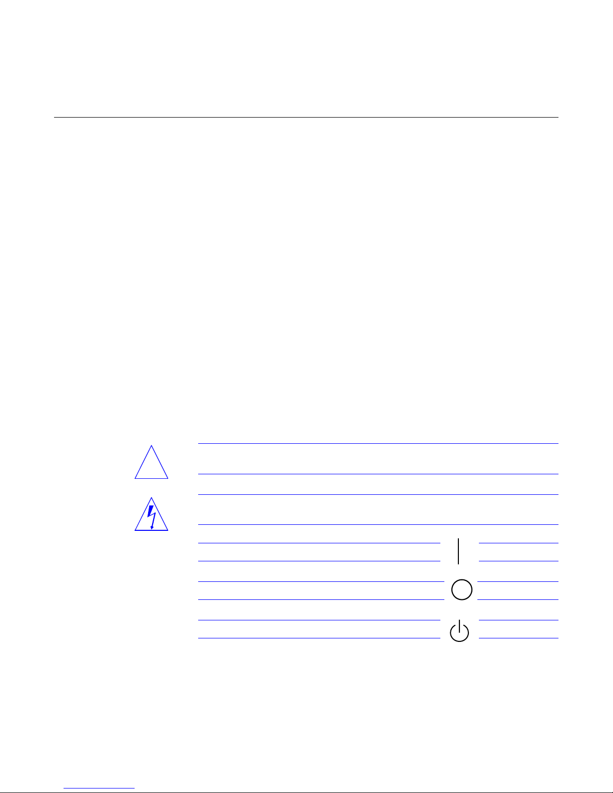
Symbols
The following symbols, which appear in this book, mean:
voltage and frequency inscribed on the equipment’s electrical rating label.
Dangerous voltages may be present. Conductive foreign objects could
produce a short circuit that could cause fire, electric shock, or damage to
your equipment.
Caution – Risk of personal injury and equipment damage. Follow the
!
x 2 Gbyte Standard Connector Disk Drive Installation Manual—May 1995
instructions.
Warning – Hazardous voltages are present. To reduce the risk of electric shock
and danger to personal health, follow the instructions.
On – Applies DC power to the system.
Off – Removes DC power from the system.
Standby – Removes DC power from the system.
Page 11
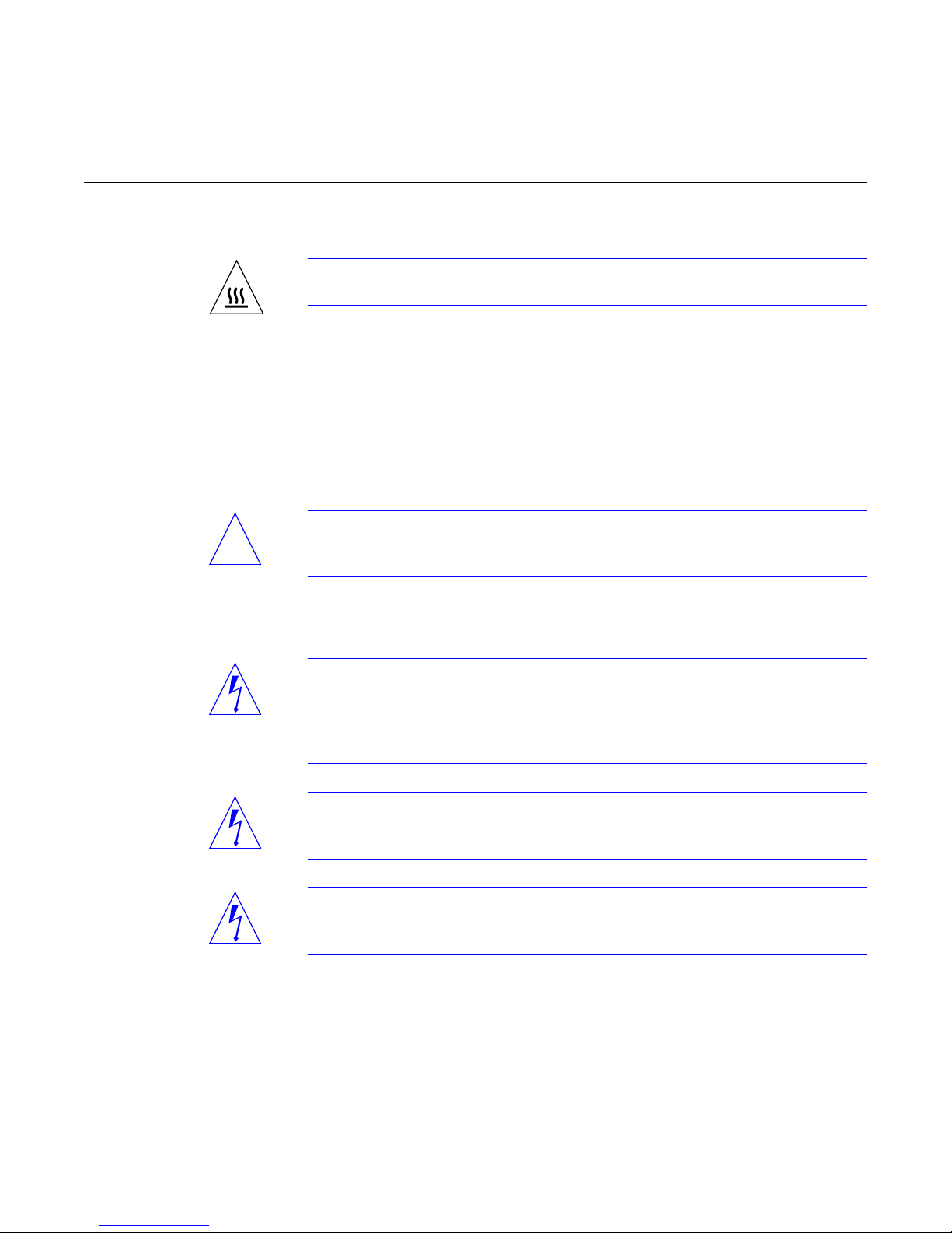
Caution – Hot surface. Avoid contact. Surfaces are hot and may cause personal
injury if touched.
Modification to Equipment
Do not make mechanical or electrical modifications to the equipment. Sun
Microsystems Computer Corporation is not responsible for regulatory
compliance of a modified Sun product.
Placement of a Sun Product
Caution – To ensure reliable operation of your Sun product and to protect it
!
from overheating, openings in the equipment must not be blocked or covered. A
Sun product should never be placed near a radiator or heat register.
Power Cord Connection
Warning – Sun products are designed to work with single-phase power systems
having a grounded neutral conductor. To reduce the risk of electrical shock, do
not plug Sun products into any other type of power system. Contact your
facilities manager or a qualified electrician if you are not sure what type of
power is supplied to your building.
Warning – Not all power cords have the same current ratings. Household
extension cords do not have overload protection and are not meant for use with
computer systems. Do not use household extension cords.
Warning – Your Sun product is shipped with a grounding type (3-wire) power
cord. To reduce the risk of electric shock, always plug the cord into a grounded
power outlet.
Preface xi
Page 12

Cover
Warning – The power switch of this product functions as a standby type device
only. The power supply plug is intended for use as the primary disconnect
device. The product must be installed near the socket outlet such that the socket
outlet is readily accessible.
You must remove the cover of your Sun computer system unit in order to add
cards, memory, or internal storage devices. Be sure to replace the top cover
before powering up your computer system.
Warning – It is not safe to operate Sun products without the top cover in place.
Failure to take this precaution may result in personal injury and system damage.
xii 2 Gbyte Standard Connector Disk Drive Installation Manual—May 1995
Page 13
BeforeYouStart
This chapter:
• Gives information about unpacking a new disk drive
• Lists the tools and equipment required to install a 2.1 Gbyte standard
• Provides software commands to shut down your operating system
• Describes the drive jumper settings
• Points you to the proper chapter for information specific to your system
Unpacking the Disk Drive
Caution – Make sure you handle the drive carefully. Any jarring movement or
!
hard impact could damage the drive.
When you unpack the disk drive from the shipping box:
1. Compare the packing list with the hardware you received.
1
connector hard disk drive in a Desktop Disk Pack and a Multi-Disk Pack
2. Place the drive on an antistatic surface, (such as the antistatic bag in
3. Save the box and the packing material in case you have to ship the drive
which the drive was shipped), with the printed circuit board (PCB) side
up.
at some future date.
1-1
Page 14

1
Mounting Hardware
The drive is a standard connector, 2.1 Gbyte SCSI low profile disk drive. It is
approximately 1 inch high and 3.5 inches wide. It supports fast SCSI at
10 Mbytes per second.
When you examine your 2.1 Gbyte disk drive, locate the label that has the Sun
part number to determine which vendor manufactured it. Disks with the
370-2067 part number are manufactured by Seagate, disks with the 370-1957
part number are from IBM. While all performance specifications are the same
for both drives, the jumper locations and settings are different. Once you have
identified which drive you have, follow the instructions for that specific drive
only.
When you unpack the disk drive, remove the plastic bags that contain various
mounting brackets, screws, grommets and cables. The bags are labeled:
• Multi-Disk Pack
• Desktop Disk Pack
Open only the appropriate bag for your system. Put the other bags aside.
1-2 2 Gbyte Standard Connector Disk Drive Installation Manual—May 1995
Page 15

Tools and Equipment
• Phillips screwdriver, #2
• Container for screws
• Needlenose pliers (for disk drive jumper settings)
• Antistatic mat or the antistatic bag in which the disk drive was shipped
• Disposable antistatic wrist strap
• SCSI regulated terminator
Verifying the Software Environment Version
Before you begin any procedures, verify which software environment you have
running on your system:
♦ Type uname -rs and press Return.
If the message displayed is: Your software environment is:
SunOS 5.x Solaris 2.x
SunOS 4.1.3_U1 Version B Solaris 1.1.1 SunSoft Version B
1
SunOS 4.1.4 Solaris 1.1.2
Shutting Down the System
Before you can install the disk drive, you must shut down the system. If you
omit a step, the system may fail to boot, or fail to correctly configure the disk
drive.
• To shut down the Solaris 2.x software environment, proceed to the next
• To shut down the Solaris 1.1.x software environment, see the section“Solaris
BeforeYouStart 1-3
section.
1.1.x Software Environment” on page 1-6.
Page 16
1
Solaris 2.x Software Environment
1. Become superuser by typing su and your superuser password.
If you do not know your superuser password, contact your system
administrator.
machine_name% su
Password: superuser password
machine_name#
The root prompt (#) is displayed.
Caution – The system will not recognize the new device unless you follow the
!
shutdown procedures for your operating system. Only Solaris 2.x software
uses the touch /reconfigure command to ensure autoconfiguration when
the system is powered on.
2. Type touch /reconfigure.
machine_name# touch /reconfigure
This command ensures that the operating system checks for the presence of
any newly installed peripheral devices when you power on or boot your
system later.
If you omit this step, you can still automatically configure the new drive
when the system boots by using the -r option:
ok# boot -r
Note – If your system is acting as a server, inform the mounted users that you
are shutting the system down as described in Step 3. If your system is a standalone system, use the halt, shutdown,orinit 0 command instead.
1-4 2 Gbyte Standard Connector Disk Drive Installation Manual—May 1995
Page 17
1
3. Type /usr/sbin/shutdown -y -g30 -i0 and press Return.
tutorial# /usr/sbin/shutdown -y -g30 -i0
.
.
.
.
ok
Note – The0ing30 and i0 is a zero.
A message is sent notifying all users who are logged in that they have 30
seconds (-g30) before the system begins to shut down. The ok or > prompt
is displayed after the operating environment is shut down.
4. At the > or ok prompt, turn the on/off switch to the off (O) position for
each device in the following order:
a. Peripherals
b. Desktop system
c. Monitor
Warning – Be sure all power switches are turned to the off (O) position. The
green light emitting diodes (LEDs) on all units should not be lit and the power
supply fans should not be running. Leave all power cords plugged into each
unit and wall outlet(s) to prevent damage to the equipment.
Caution – After turning off the power, always wait 10 seconds before turning it
!
on again. This pause prevents possible damage to power supply components
in the desktop system.
BeforeYouStart 1-5
Page 18
1
Solaris 1.1.x Software Environment
1. Become superuser by typing su and your superuser password.
If you do not know your superuser password, contact your system
administrator.
machine_name% su
Password: superuser password
machine_name#
The root prompt (#) is displayed.
Note – If your system is acting as a server, inform the mounted users that you
are shutting the system down as described in Step 2. If your system is a standalone system, use the halt, shutdown,orinit 0 command instead.
2. Shut down the system by typing /usr/etc/shutdown -h +, the time to
shutdown in minutes, and a message to other users on the network.
# /usr/etc/shutdown -h + time in minutes “message”
1-6 2 Gbyte Standard Connector Disk Drive Installation Manual—May 1995
Page 19
1
In the following example, the system will be shut down in five minutes and
a warning will be sent, at intervals, to all users on the network. This allows
users with mounted file systems time to save their work.
Isis# /usr/etc/shutdown -h +5 “Isis going down in 5 minutes”
Shutdown at time (in 5 minutes) [pid xxx]
Isis#
***System shutdown message from Isis***
System going down in x minutes
...system going down in x minutes
***Shutdown message from Isis***
FINAL System shutdown message from Isis
System going down in 30 seconds
System going down immediately
System shutdown time has arrived
date time Isis shutdown:halt by Isis
date time Isis syslogd:going down on signal x
syncing file systems...done
Halted
Type help for more information
ok
3. At the > or ok prompt, turn the on/off switch to the off (O) position for
each device in the following order:
a. Peripherals
b. Desktop system
c. Monitor
Warning – Be sure all power switches are turned to the off (O) position. The
green light emitting diodes (LEDs) on all units should not be lit and the power
supply fans should not be running. All power cords should remain plugged
into each unit and wall outlets to prevent damage to the equipment.
Caution – Always allow 10 seconds between turning off the power and turning
!
it on again. This pause prevents possible damage to power supply components
in the desktop system.
BeforeYouStart 1-7
Page 20

1
Locating the Jumpers and Verifying their Settings
Each SCSI device in your system needs a specific and unique SCSI address.
This section identifies the 2.1 Gbyte disk drive jumpers and provides jumper
settings for all supported systems except the Multi-Disk Pack.
For Multi-Disk Pack disk drive jumper locations and settings, see “Setting
Jumpers and Preparing the Disk Drive for Installation” in Chapter 3, “MultiDisk Pack.”
Note – Make sure you are wearing a wrist strap when you handle the drive to
check the jumper settings. Make sure that the external power cord is connected
to the subsystem and power outlet. Do not have the subsystem powered on
when you do this.
1. Make sure the drive is on an antistatic surface with the PCB side visible.
2. Locate the jumper blocks on the drive and verify that the pins are
correctly jumpered.
• See Figure 1-1 on page 1-9 for the IBM drive.
• See Figure 1-2 on page 1-11 for the Seagate drive.
1-8 2 Gbyte Standard Connector Disk Drive Installation Manual—May 1995
Page 21

Pin 4
• 6
• 8
• 10
• 12
• 14
• 16
• 18
• 20
• 22
• 24
• 26
• 28
• 30
1
Pin 32
34567
8
11
1314151617
12
10
19202122232425262728293031
18
32
Figure 1-1 IBM Drive Jumper Settings
IBM Drive Jumper Descriptions
Table 1-1 lists the factory configured jumpers on the IBM drive. Table 1-2 lists
the SCSI target address settings.
Table 1-1 IBM Disk Drive Option Jumper Block
Description Jumper Pins: Factory Set
(Reserved) 1 and 2
SCSI ID 2 3 and 4
SCSI ID 1 5 and 6
SCSI ID 0 7 and 8
Auto Start 11 and 12 yes
Enable Active Termination 13 and 14
Master Sync (15)
Slave Sync (16)
External Acitivity LED 17 and 18
BeforeYouStart 1-9
Page 22

1
Table 1-1 IBM Disk Drive Option Jumper Block
Description Jumper Pins: Factory Set
Write Protect 19 and 20
Auto Start Delay 21 and 22
Option Block Mode 23 and 24 yes
Disable Sync Negotiations 25 and 26
Disable SCSI Parity 27 and 28
Disable Unit Attention 29 and 30
Customizing 31 and 32
.
Table 1-2 IBM Drive SCSI Address Settings
Pins 3
Targets
0
1X
2X
3XX
4X
5X X
6XX
and 4
Pins 5
and 6
Pins7and
8
Note – Target address 7 is reserved for SCSI controller.
1-10 2 Gbyte Standard Connector Disk Drive Installation Manual—May 1995
Page 23

• 5
Pin 6
J1
• 3
• 4
• 1
Pin 2
Pin 1
• 3
jumper
• 9
• 5
• 7
J2
• 11
• 13
• 15
1
Pin 17
Figure 1-2 Seagate Drive Jumper Settings
Seagate Drive Jumper Descriptions
Table 1-3 describes the configuration jumpers. Table 1-4 lists the SCSI target
address settings
Table 1-3 Seagate Configuration Jumper Descriptions
Description Jumper: Factory Set
(Reserved) J2-1,2,3,4,13,14,15,
16,17,18
Delay Motor Start J2-11 to J2-12
Motor Start J2-9 to J2-10 yes
Write Protect -On (disables writIng J2-7 to J2-8
Disable Parity Check J2-5 to J2-6
Terminator Power from Drive J1-1 to J1-2
BeforeYouStart 1-11
Page 24

1
Table 1-3 Seagate Configuration Jumper Descriptions
Description Jumper: Factory Set
Terminator Power to SCSI bus J1-1 to J1-3
Terminator Power from SCSI bus J1-2 to J1-4
Terminator Power to SCSI bus and
drive
Table 1-4 Seagate SCSI Address Settings
J4-9 to
Targets
0
1X
2X
3XX
4X
5X X
6XX
J4-10
J4-11 to
J4-12
J1-1 to J1-3 and
J1-2 to J1-4
J4-13 to
J4-14
Note – Target address 7 is reserved for SCSI controller.
1-12 2 Gbyte Standard Connector Disk Drive Installation Manual—May 1995
Page 25

DesktopDiskPack
The tasks required to remove and replace a disk drive in the Desktop Disk
Pack (DDP) are listed below. Tasks which are common to all systems are
described in the Preface and Chapter 1.
Read the Safety Precautions and Safety Agency Compliance page -x
Verify the version of your software environment page 1-3
Shut down your system page 1-3
Remove the cover page 2-3
Remove the disk drive (if necessary) page 2-6
Set the SCSI target address page 2-10
Install the new disk drive page 2-10
Replace the cover page 2-4
Turn on power to your system page 2-15
Configure your system page 2-15
2
2-1
Page 26

2
Figure 2-1 shows major internal components of the Desktop Disk Pack.
Top cover
I/O assembly
Power supply
assembly
Disk drive
Figure 2-1 Components of the Desktop Disk Pack
Opening and Closing the Desktop Disk Pack
1. Read the “Safety Agency Compliance” section in the Preface for safety
precautions.
2. Read Chapter 1 to determine which tools are required, how to shut down
the system, and how to verify jumper settings on the drive.
Flex cable
Mounting plate
2-2 2 Gbyte Standard Connector Disk Drive Installation Manual—May 1995
Page 27

Removing the DDP Cover
1. Turn off the power to your system unit and make sure the external power
cord is plugged in to the DDP and to the power source.
See “Shutting Down the System” on page 1-3.
2. Locate the holes on both of the side vented panels and insert a small (2 to
3mm) screwdriver into one of the specific holes shown in Figure 2-2.
2
Figure 2-2 Removing the Cover
3. Push the screwdriver into the hole to release the catch. Repeat this on the
4. Lift the rear of the cover up slightly and push it forward off of the front
5. Attach a wrist strap to your wrist and then to the power supply.
Desktop Disk Pack 2-3
other side to release that catch.
tabs.
Set the cover aside.
See Figure 2-3.
Page 28

2
Figure 2-3 Attaching the Wrist Strap
Replacing the DDP Cover
1. Make sure there are no loose tools or screws in the unit, and that all
internal components are seated properly.
2. Make sure that all internal cable connections are secure, and that the
power supply cord is tucked inside the system to avoid pinching the
wiring when you replace the cover.
3. Remove the wrist strap.
4. Holding the cover at an angle, engage the front tabs of the cover with the
front of the unit.
See Figure 2-4.
2-4 2 Gbyte Standard Connector Disk Drive Installation Manual—May 1995
Page 29

2
Figure 2-4 Replacing the Cover
5. Lower the rear of the cover.
6. Press down firmly on the back end of the cover until you hear a click of
both cover catches engaging.
Desktop Disk Pack 2-5
Page 30

2
Removing the Disk Drive
1. Disconnect the flex cable from the SCSI target address switch.
See Figure 2-5. The flex cable is fragile and must be handled carefully.
2. Disconnect the power supply connector from the LED cable on the
mounting plate.
See Figure 2-5.
LED cable
Power supply
connector
Figure 2-5 Disconnecting the Flex Cable and the Power Supply Connector
2-6 2 Gbyte Standard Connector Disk Drive Installation Manual—May 1995
Flex cable
Page 31

2
3. Disengage the retaining clip on the bottom of the DDP by reaching under
the DDP and pulling down on the clip to clear it from the mounting plate.
You can use a coin to pull down the clip so you can slide out the mounting
plate. See Figure 2-6.
Retaining clip
Figure 2-6 Disengaging the Retaining Clip
4. Slide the disk drive assembly, consisting of the disk drive and the
mounting plate, partially out of the chassis (only about 1 to 2 inches).
Do not completely remove the drive assembly. You just want to create a little
room to disconnect the cables before removing the assembly completely. See
Figure 2-7 on the next page.
Desktop Disk Pack 2-7
Page 32

2
5. Disconnect the power supply connector from the disk drive and the
internal SCSI cables of the I/O assembly from the disk drive.
See Figure 2-7.
6. Slide the disk drive assembly completely out of the DDP.
Power supply
connector
SCSI cables
Figure 2-7 Sliding the Disk Drive Assembly Out of the Chassis and
2-8 2 Gbyte Standard Connector Disk Drive Installation Manual—May 1995
Disconnecting the Cabling
Page 33

7. Remove the four screws securing the drive to the mounting plate.
See Figure 2-8. Place the drive on an antistatic surface.
8. Disconnect the flex cable from the disk drive.
See Figure 2-11 on page 2-12 for the flex cable location. The flex cable is
fragile and must be handled carefully.
2
Figure 2-8 Removing the Drive from the Mounting Plate
Desktop Disk Pack 2-9
Page 34

2
Installing a Disk Drive:
1. Locate the SCSI address jumpers on your disk drive as shown in
Chapter 1, “Before You Start.”
• If you have an IBM disk drive, see Figure 1-1 on page 1-9.
• If you have a Seagate disk drive, see Figure 1-2 on page 1-11.
2. Remove the jumpers from the ID Select pins of the SCSI address jumper
block.
3. Make sure the SCSI address switch on your system unit is set to the
correct target address. If you need to change the address:
a. Locate the switch on the system unit.
Figure 2-9 shows the switch location on the DDP.
b. Decide on an address that is not shared by any other device on your
SCSI bus.
The most common settings for a DDP are 0 or 2. As a general rule, each
device on the SCSI bus must be set at a different target address.
c. Press the button on the top or bottom of the switch until the desired
address number appears in the window.
Target address switch
Figure 2-9 SCSI Target Address Switch Location
4. Make sure the wrist strap is properly attached.
See Figure 2-3 on page 2-4.
2-10 2 Gbyte Standard Connector Disk Drive Installation Manual—May 1995
Page 35

2
5. Attach the mounting plate to the bottom of the disk drive by aligning the
holes in the plate with the screw holes in the drive and installing four
screws.
See Figure 2-10.
Figure 2-10 Attaching the Drive to the Mounting Plate
6. Slide the disk drive assembly partially into place.
See Figure 2-12.
7. Connect the SCSI cable and the power supply connector to the disk drive.
See Figure 2-12. The connectors are keyed so they will only fit one way.
Desktop Disk Pack 2-11
Page 36

2
8. Connect the flex cable to the disk drive.
See Figure 2-11.
Caution – The flex cable is fragile and can be easily damaged. Make sure you
!
take extra precaution in handling it.
flex cable
• 6
• 2
• 3
• 4
• 5
• 7
• 8
Pin 1
• 9
Pin 10
Seagate disk drive
flex cable
• 18
• 20
• 22
• 24
• 26
• 28
Pin 4
• 6
• 8
• 10
• 12
• 14
• 16
• 30
Pin 32
IBM disk drive
Figure 2-11 Connecting the Flex Cable
9. Connect the other end of the flex cable to the SCSI target address switch.
2-12 2 Gbyte Standard Connector Disk Drive Installation Manual—May 1995
Page 37

SCSI cable
2
Power supply
connector
Flex cable
Figure 2-12 Sliding the Drive into Place and Connecting the Cables
10. Slide the disk drive assembly completely into the base, making sure the
assembly engages the retaining clip on the interior floor of the DDP.
See Figure 2-13.
Caution – Be sure the drive assembly snaps securely in place with the
retaining clip. If the drive is not placed back in the base all the way, the cover
will not close properly and the front tabs could be damaged.
Desktop Disk Pack 2-13
Page 38

2
Power supply
connector
LED cable
Figure 2-13 Connecting the Power Supply Connector to the LED
11. Connect the power supply connector to the LED cable on the mounting
plate.
See Figure 2-13.
12. Remove the wrist strap and replace the cover.
See “Replacing the DDP Cover” on page 2-4.
Note – You must use a regulated SCSI terminator on the DDP, or on the last
device in the daisy chain if there are multiple external devices. The 2.1 Gbyte
disk drive is a fast SCSI device and requires the regulated SCSI terminator.
See Appendix B for descriptions of SCSI ports, types of connections, SCSI
termination, and cable length.
2-14 2 Gbyte Standard Connector Disk Drive Installation Manual—May 1995
Page 39

Completing the Drive Installation
System configuration occurs after a system is successfully powered on. If the
system shutdown was performed according to the procedure in Chapter 1,
your system should automatically configure when you power on the system.
To complete the installation of the 2.1 Gbyte disk drive into your Desktop Disk
Pack:
1. Go to the Handbook for SMCC Peripherals that came with your operating
system.
2. Follow the instructions in the “Configuring the System” section.
2
Desktop Disk Pack 2-15
Page 40

2
2-16 2 Gbyte Standard Connector Disk Drive Installation Manual—May 1995
Page 41

Multi-DiskPack
This chapter explains how to remove a disk drive and how to install a
2.1 Gbyte hard disk drive in the Multi-Disk Pack unit. Tasks which are
common to all systems are described in the Preface and Chapter 1.
Read the Safety Precautions and Safety Agency Compliance page -x
Verify the version of your software environment page 1-3
Shut down your system page 1-3
Remove the cover page 3-2
Remove the disk drive assembly page 3-5
Remove the disk drive(s) from the assembly page 3-7
Set disk drive SCSI address page 3-8
Install the new disk drive in the disk drive assembly page 3-12
Replace the disk drive assembly page 3-13
Replace the cover page 3-3
Turn on power to your system page 3-16
Configure your system page 3-16
3
3-1
Page 42

3
Opening and Closing the Multi-Disk Pack Unit
1. Read the “Safety Agency Compliance” section in the Preface for safety
precautions.
2. Read Chapter 1 to determine which tools are required, how to shut down
the system, and how to verify jumper settings on the drive.
Removing the Multi-Disk Pack Cover
1. Turn off the power to your Multi-Disk Pack and make sure the external
power cord is plugged in to the Multi-Disk Pack and to the power source.
See “Shutting Down the System” on page 1-3.
2. Remove the Phillips screw in the lock block.
See Figure 3-1.
3. Placing your hands over both sides, lift the cover up and off the unit.
Figure 3-1 Removing the Lock Block and Lifting the Cover Off
3-2 2 Gbyte Standard Connector Disk Drive Installation Manual—May 1995
Lock block
Page 43

4. Attach a wrist strap to your wrist and then to the power supply.
See Figure 3-2 and Figure 3-3.
Figure 3-2 Attaching the Wrist Strap
Power supply
location
3
Figure 3-3 Location of the Multi-Disk Pack Power Supply
Replacing the Multi-Disk Pack Cover
1. Remove the wrist strap from the power supply and then from your wrist.
2. Position the cover over the unit with the front of the cover oriented over
3. Tilt the rear of the cover up and carefully slide the cover towards the rear
Multi-Disk Pack 3-3
the front of the base.
of the unit.
See Figure 3-4.
Page 44

3
Figure 3-4 Replacing the Cover
Caution – The front of the cover is fragile. If the tabs do not hook properly on
!
your first attempt, do not force the cover to the rear of the unit or down.
Remove the cover and attempt to position the tabs until the tabs are hooked.
4. Install the lock block on the back of the unit.
See Figure 3-1 on page 3-2.
3-4 2 Gbyte Standard Connector Disk Drive Installation Manual—May 1995
Page 45

Removing the Disk Drive Assembly
1. Disconnect the power supply power cable connector from its mating disk
drive power connector.
Grasp connector firmly in one hand, and with the other hand pull the power
cable connector from its mating connector. See Figure 3-5.
2. Lift up on the metal handle of the SCSI connector clip and remove it from
the SCSI port area.
See Figure 3-5.
3
Power cable
connector
SCSI
connector
clip
Figure 3-5 Removing the SCSI Connector Clip and Disconnecting the Power
3. Loosen the two captive Phillips screws on the bottom of the unit.
4. Lift the drive assembly up. Place the assembly on an antistatic mat.
Multi-Disk Pack 3-5
Connector
See Figure 3-6.
See Figure 3-6 and Figure 3-7.
Page 46

3
Captive screw
Captive screw
Figure 3-6 Removing the Drive Assembly
SCSI cable
Screws
Figure 3-7 Disk Drive Assembly on an Antistatic Mat
3-6 2 Gbyte Standard Connector Disk Drive Installation Manual—May 1995
Page 47

Removing the Disk Drive from the Disk Drive Assembly
1. Disconnect the SCSI cable and power cable from each disk drive you are
replacing.
See Figure 3-8 for connector locations on the disk drive.
SCSI data
connector
Power cable
connector
Figure 3-8 Location of SCSI Data Cable and Power Cable Connectors on a Disk Drive
3
2. Remove the Phillips screws securing the disk drive to the assembly.
See Figure 3-7 on the previous page.
3. Carefully slide the drive out of the assembly.
4. Place the drive on an antistatic mat with the PCB side up.
5. Remove the screws securing the mounting plate to the disk drive.
See Figure 3-9.
Screws
Figure 3-9 Drive with Mounting Plate Attached
Multi-Disk Pack 3-7
Page 48

3
Setting Jumpers and Preparing the Disk Drive for Installation
You can configure your drive with seven possible SCSI target address jumper
settings:
• See Figure 3-10 for the available SCSI target address jumper settings on an
IBM drive.
• See Figure 3-11 for the available SCSI target address jumper settings on a
Seagate drive.
The SCSI target address jumper settings on the replacement drives are factory
set to SCSI address 3.
SCSI target address:
0123456
A0
A2
A1
A0 A1 A2
• 6
Pin 4
• 8
• 10
A0
• 12
• 14
A1
• 16
• 18
A2
• 20
• 22
• 24
A0
• 26
• 28
A1
• 30
A2
Pin 32
A0
A1
A2
A0
A1
A2
A0
A1
A2
A0
A1
A2
Figure 3-10 Available SCSI Target Address Jumper Settings—IBM Drive
3-8 2 Gbyte Standard Connector Disk Drive Installation Manual—May 1995
Page 49

3
SCSI target address:
012345
A2 A1 A0 A2 A1 A0 A2 A1 A0A2 A1 A0A2 A1 A0A2 A1 A0A2 A1 A0
6
A2 A1 A0
• 6
• 2
• 3
• 4
• 5
• 7
• 8
Pin 1
• 9
Pin 10
Figure 3-11 Available SCSI Target Address Jumper Settings—Seagate Drive
Multi-Disk Pack 3-9
Page 50

3
1. Compare the drive configuration jumper settings to Figure 3-12 or
Figure 3-12.
• If your drive configuration jumper settings are the same as shown in the
figure for your drive, leave them as they are.
• If the jumper settings are not the same, use needlenose pliers and change
the jumpers to match the settings shown for your particular drive.
34567
8
11
1314151617
12
10
19202122232425262728293031
18
jumpers
• 18
• 20
• 22
• 24
• 26
• 28
Pin 4
• 6
• 8
• 10
• 12
• 14
• 16
• 30
Pin 32
Figure 3-12 Configuration Jumper Settings—IBM Disk Drive
32
3-10 2 Gbyte Standard Connector Disk Drive Installation Manual—May 1995
Page 51

• 5
Pin 6
J1
• 3
• 4
• 1
Pin 2
Pin 1
• 3
jumper
• 9
• 5
• 7
J2
• 11
• 13
• 15
3
Pin 17
Figure 3-13 Configuration Jumper Settings — Seagate Disk Drive
2. Install the mounting plate that you received with your new drive to the
PCB side of the disk drive.
See Figure 3-14. .
Screws
Figure 3-14 Disk Drive With Mounting Plate Attached
3. Replace the drive in the assembly.
Multi-Disk Pack 3-11
Page 52

3
Replacing a Disk Drive in the Disk Drive Assembly
1. Slide the drive into the assembly.
The PCB side of the disk drive will face down, and the SCSI data and power
connectors face the power supply.
2. Insert and tighten the screws securing the drive to the assembly.
See Figure 3-7 on page 3-6.
3. Connect the SCSI data cables to the SCSI data connectors of each drive.
See Figure 3-15 on the next page. The connectors are keyed. Make sure that
you connect the proper connector, labeled P2 through P4, to the proper SCSI
connector on the disk drive.
P5
P2
P3
Figure 3-15 Connecting the SCSI Data Cables to the Disk Drives
4. Connect the power cable to the power connector of each disk drive.
See Figure 3-16.
5. Install the disk drive assembly into the Multi-Disk Pack unit.
3-12 2 Gbyte Standard Connector Disk Drive Installation Manual—May 1995
P4
Page 53

P4
P2
Figure 3-16 Connecting the Power Cables to the Disk Drives
3
P1
P3
Replacing the Disk Drive Assembly
1. Move the power supply cable leading from the I/O bracket/fan out of
the unit.
2. Lower the drive assembly. Rock it back and forth to make sure the drive
assembly sits properly.
3. Tighten the two captive screws on the bottom of the assembly.
You may have to shift the drive assembly back and forth until the holes are
aligned with the captive screws. See Figure 3-17.
Note – Do not use a power screwdriver on a captive screw.
Multi-Disk Pack 3-13
Page 54

3
Power cable
connector
Captive screw
Captive screw
Figure 3-17 Lowering the Drive Assembly
Hooks
SCSI connector clip
Tabs
4. Tuck the power supply cable leading from the fan into the unit.
5. Install the SCSI connector clip into the SCSI port area.
See Figure 3-17.
a. Lower the SCSI connector clip.
Align the two metal tabs at the bottom of the SCSI connector clip
between the plastic molded tabs on the lower SCSI port opening of the
unit.
You should see both SCSI connectors in the SCSI connector openings on
the rear panel.
b. Holding the top of the SCSI connector clip, lift up on the SCSI
connector clip.
The hooks on the top of the SCSI connector clip will lock into place on
the rear of the unit.
3-14 2 Gbyte Standard Connector Disk Drive Installation Manual—May 1995
Page 55

3
Note – Make sure that the SCSI connector clip is completely and
securely inserted. If it is loose, reinstall the SCSI connector clip. You may have
to install the clip to a lower position in the opening then raise the clip slightly
by lifting it and hooking the tabs to attach it to the unit and secure the clip.
6. Make sure that the SCSI cable is held in place by the two fingers on the
top of the disk drive assembly
See Figure 3-18.
Fingers securing
SCSI cable
Figure 3-18 SCSI Cable Held in Place by Fingers on Disk Drive Assembly
7. Connect the power cable labeled P0 to the disk drive power connector.
See Figure 3-17.
8. Detach the wrist strap and replace the cover.
See “Replacing the Multi-Disk Pack Cover” on page 3-3.
Note – You must use a regulated SCSI terminator on the Multi-Disk Pack, or on
the last device in the daisy chain if there are multiple external devices. The
2.1 Gbyte disk drive is a fast SCSI device and requires the regulated SCSI
terminator. See Appendix B for descriptions of SCSI ports, types of
connections, SCSI termination, and cable length.
Multi-Disk Pack 3-15
Page 56

3
Completing the Drive Installation
System configuration occurs after a system is successfully powered on. If the
system shutdown was performed according to the procedure in Chapter 1,
your system should automatically configure when you power on the system.
To complete the installation of the 2.1 Gbyte disk drive into your Multi-Disk
Pack:
1. Go to the Handbook for SMCC Peripherals that came with your operating
system.
2. Follow the instructions in the “Configuring the System” section.
3-16 2 Gbyte Standard Connector Disk Drive Installation Manual—May 1995
Page 57

ComplianceStatements
This appendix contains the Safety Compliance statements translated into
French, German, and Spanish. For the English version, see the Preface. These
instructions explain how to work safely with the internal components of your
system.
Conformité aux Normes de Sécurité
Cette préface traite des mesures de sécurité qu’il convient de suivre pour
l’installation d’un produit Sun Microsystems, Inc.
Mesures de Sécurité
Pour votre protection, veuillez prendre les précautions suivantes pendant
l’installation du matériel:
• Suivre tous les avertissements et toutes les instructions inscrites sur le
matériel.
• Vérifier que la tension et la fréquence de la source d’alimentation électrique
correspondent à la tension et à la fréquence indiquées sur l’étiquette de
classification de l’appareil.
A
A-1
Page 58

A
Symboles
!
• Ne jamais introduire d’objet quel qu’il soit dans une des ouvertures de
l’appareil. Vous pourriez vous trouver en présence d’éléments haute
tension. Tout objet conducteur introduit de la sorte pourrait produire un
court-circuit qui entraînerait des flammes, des risques d’électrocution ou des
dégâts matériels.
Vous trouverez ci-dessous la signification des différents symboles utilisés:
Warning – Avertissement – Présence de tensions dangereuses. Pour éviter les
risques d’électrocution et de danger pour la santé physique, veuillez suivre les
instructions.
Caution – Attention – Risques de blessures corporelles et de dégâts matériels.
Veuillez suivre les instructions.
Warning – Marche – Le commutateur marche/arrêt principal est en position
de marche.
Warning – Arrêt – Le commutateur marche/arrêt principal est en position
d’arrêt.
Modification du Matériel
Ne pas apporter de modification mécanique ou électrique au matériel. Sun
Microsystems, Inc., n’est pas responsable de la conformité réglementaire d’un
produit Sun qui a été modifié.
A-2 2 Gbyte Standard Connector Disk Drive Installation Manual—May 1995
Page 59

Positionnement d’un Produit Sun
Caution – Attention – Pour assurer le bon fonctionnement de votre produit Sun
!
et pour l’empêcher de surchauffer, il convient de ne pas obstruer ni recouvrir les
ouvertures prévues dans l’appareil. Un produit Sun ne doit jamais être placé à
proximité d’un radiateur ou d’une source de chaleur.
Connexion du Cordon d’Alimentation
Warning – Avertissement – Les produits Sun sont conçus pour fonctionner avec
des alimentations monophasées munies d’un conducteur neutre mis à la terre.
Pour écarter les risques d’électrocution, ne pas brancher de produit Sun dans un
autre type d’alimentation secteur. En cas de doute quant au type d’alimentation
électrique du local, veuillez vous adresser au directeur de l’exploitation ou à un
électricien qualifié.
Warning – Avertissement – Tous les cordons d’alimentation n’ont pas
forcément la même puissance nominale en matière de courant. Les rallonges
d’usage domestique n’offrent pas de protection contre les surcharges et ne sont
pas prévues pour les systèmes d’ordinateurs. Ne pas utiliser de rallonge d’usage
domestique avec votre produit Sun.
A
Couvercle
!
Warning – Avertissement – Votre produit Sun a été livré équipé d’un cordon
d’alimentation à trois fils du type avec prise de terre. Pour écarter les risques
d’électrocution, toujours brancher ce cordon dans une prise mise à la terre.
Caution – Attention – Il est dangereux de faire fonctionner un produit Sun sans
le couvercle en place. Si l’on néglige cette précaution, on encourt des risques de
blessures corporelles et de dégâts matériels.
Compliance Statements A-3
Page 60

A
SicherheitsbehördlicheVorschriften
In diesem Anhang werden die Sicherheitsmaßnahmen beschrieben, die bei der
Installation eines Produkts von Sun Microsystems, Inc., zu befolgen sind.
Sicherheitsmaßnahmen
Beachten Sie zu Ihrem eigenen Schutz die folgenden Sicherheitsmaßnahmen,
wenn Sie Ihre Geräte aufbauen:
• Beachten Sie alle auf den Geräten angebrachten Warnungen und
Anweisungen.
• Vergewissern Sie sich, daß Spannung und Frequenz Ihrer Stromquelle mit
der Spannung und Frequenz übereinstimmen, die auf dem Etikett mit den
elektrischen Nennwerten des Geräts angegeben sind.
Stecken Sie niemals irgendwelche Gegenstände in Öffnungen in den Geräten.
Es können gefährliche Spannungen vorliegen. Leitfähige fremde Gegenstände
könnten einen Kurzschluß verursachen, der zu Feuer, Elektroschock oder einer
Beschädigung Ihrer Geräte führen könnte.
Symbole
Die verwendeten Symbole haben die folgende Bedeutung:
Warning – Warnung – Gefährliche Spannungen. Zur Reduzierung des
Elektroschockrisikos und der Gesundheitsgefährdung die Anweisungen
befolgen.
Caution – Vorsicht – Gefahr von Personenverletzung und Geräteschaden.
!
A-4 2 Gbyte Standard Connector Disk Drive Installation Manual—May 1995
Anweisungen befolgen.
Caution – Ein – Der Hauptschalter steht auf Ein.
Caution – Aus – Der Hauptschalter steht auf Aus.
Page 61

Änderung der Geräte
Nehmen Sie keine mechanischen oder elektrischen Änderungen an den
Geräten vor. Sun Microsystems, Inc., ist nicht verantwortlich für die
Einhaltung behördlicher Vorschriften, wenn an einem Sun-Produkt
Änderungen vorgenommen wurden.
Aufstellungsort eines Sun-Produkts
Caution – Vorsicht – Um einen zuverlässigen Betrieb Ihres Sun-Produkts zu
!
gewährleisten und es vor Überhitzung zu schützen, dürfen die Öffnungen im
Gerät nicht blockiert oder bedeckt werden. Ein Sun-Produkt sollte niemals in
der Nähe eines Heizkörpers oder einer Heizluftklappe aufgestellt werden.
Anschluß des Stromkabels
Warning – Warnung– Sun-Produkte sind für den Betrieb mit EinphasenStromsystemen mit einem geerdeten Mittelleiter vorgesehen. Um die
Elektroschockgefahr zu reduzieren, schließen Sie Sun-Produkte nicht an andere
Arten von Stromsystemen an. Wenden Sie sich an Ihren Anlagenleiter oder
einen qualifizierten Elektriker, wenn Sie sich nicht sicher sind, welche Art von
Strom Ihr Gebäude erhält.
A
Warning – Warnung– Nicht alle Stromkabel besitzen die gleichen
Stromnennwerte. Haushaltsverlängerungsschnuren haben keinen
Überlastungsschutz und sind nicht zum Gebrauch mit Computersystemen
bestimmt. Benutzen Sie keine Haushaltsverlängerungsschnuren für Ihr SunProdukt.
Warning – Warnung – Ihr Sun-Produkt wird mit einem Erdungs-Netzkabel (3Leiter) geliefert. Um die Elektroschockgefahr zu reduzieren, schließen Sie das
Kabel nur an eine geerdete Steckdose an.
Compliance Statements A-5
Page 62

A
Obere Abdeckung
Caution – Vorsicht – Der Betrieb von Sun-Produkten ohne obere Abdeckung ist
!
Conformidad Con La Agencia de Seguridad
Precauciones de Seguridad
nicht sicher. Bei Nichteinhalten dieser Vorsichtsmaßregel kann es zu
Personenverletzung und Systemschäden kommen.
Este prólogo presenta las precauciones de seguridad a seguir cuando se instala
un producto de Sun Microsystems, Inc.
Para su protección, observe las siguientes preocupaciones de seguridad al
instalar su equipo:
• Siga todos los avisos e instrucciones marcados en el equipo.
• Asegúrese de que el voltaje y la frecuencia de su fuente de alimentación
sean iguales al voltaje y frecuencia indicados en la etiqueta de la capacidad
eléctrica nominal del equipo.
No introduzca jamás objetos de ninguna clase por las aberturas del equipo
porque pueden estar presentes voltajes peligrosos. Cualquier objeto conductor
extraño puede producir cortocircuito que podría causar incendio,
electrochoque o daños a su equipo.
Símbolos
Los siguientes símbolos significan:
Warning – Aviso – Hay presentes voltajes peligrosos. Siga las instrucciones
para reducir el riesgo de electrochoque y los peligros contra la salud.
Caution – Precaución– Peligro de lesión personal y daño al equipo. Siga las
!
A-6 2 Gbyte Standard Connector Disk Drive Installation Manual—May 1995
instrucciones.
Page 63

Caution – Encendido – El interruptor principal de encendido/apagado está en
la posición de encendido.
Caution – Apagado – El interruptor principal de encendido/apagado está en la
posición de apagado.
Modificaciones al Equipo
No haga modificaciones mecánicas o eléctricas al equipo. Sun Microsystems,
Inc., no se hace responsable del cumplimiento de las regulaciones de un
producto Sun si ha sido modificado.
Colocación de un Producto Sun
Caution – Precaución – Para lograr un funcionamiento seguro de su producto
!
Sun y protegerlo contra el calentamiento excesivo, no se deben bloquear o cubrir
las aberturas del aparato. Ningún producto Sun se debe colocar jamás cerca de
un radiador o una fuente térmica.
A
Conexión del Cable de Alimentación
Warning – Aviso – Los productos Sun han sido diseñados para funcionar con
sistemas de alimentación monofásicos que tengan un conductor neutro a tierra.
Para reducir el riesgo de electrochoque, no enchufe los productos Sun a ningún
otro tipo de sistema de alimentación. Si no está seguro del tipo de alimentación
eléctrica que se suministra a su edificio, consulte al administrador de la
propiedadoaunelectricista profesional.
Warning – Aviso– No todos los cables de alimentación tienen la misma
capacidad nominal de corriente. Las extensiones tipo casero no tienen protección
contra sobrecargas y no están destinadas a usarse con sistemas de computasion.
No use extensiones caseras con su producto Sun.
Compliance Statements A-7
Page 64

A
Warning – Aviso – Su producto Sun se le provee con un cable de alimentación
con salida a tierra (trifilar). Para reducir el riesgo de electrochoque, enchufe
siempre el cable a un tomacorriente con conexión a tierra.
Cubierta Superior
Caution – Precaución– Los productos Sun no pueden funcionar sin riesgo si la
!
cubierta superior no está colocada en su sitio. Si no toma esta precaución,
correrá el riesgo de lesionarse personalmente y dañar el equipo.
A-8 2 Gbyte Standard Connector Disk Drive Installation Manual—May 1995
Page 65

SmallComputerSystemsInterface
Information
This appendix describes the Small Computer Systems Interface (SCSI). Topics
covered in this appendix include:
• SCSI ports and connections
• SCSI bus length
• SCSI bus termination information
SCSI Ports and Connections
If fast SCSI devices and old-style connectors must be used in the same system,
the old-style connectors should be connected to a separate SCSI port that
doesn’t contain fast SCSI devices. Do not connect fast SCSI devices and oldstyle connectors in the same daisy chain.
Old-style connectors can be identified by a 3-row 50-pin D connector, a 50-pin
ribbon style connector, or a 50-pin “Centronics style” of a connector (1/2-inch
Front Load Tape (FLT) drive).
There is a microminiature SCSI port on the back panel of a DDP. The SCSI
connectors have 50 pins divided into two rows. You can connect the DDP your
system in two ways—direct connection or a daisy chain.
B
B-1
Page 66

B
Direct Connection
Use a direct connection when you are connecting the first SCSI device in the
SCSI bus to the desktop computer system by connecting one end of the SCSI
cable to one of the SCSI ports of the DDP, and the other end of the SCSI cable
to the SCSI port of the desktop system. You must connect a regulated SCSI
terminator to the other SCSI port of the DDP.
Note – If you install a SBus card with an additional SCSI port in the desktop
system, you can connect the DDP to the SCSI port of the SCSI card.
Daisy Chain Connection
A daisy chain connection is a means of connecting a number of SCSI peripherals
to a host system. It allows a single port on the desktop system to connect to more
than one SCSI peripheral. If you want morethan one SCSI peripheral on a bus, you
need to daisy chain.
Note – Devices with the old-style connectors (3-row 50-pin D connectors or
50-pin ribbon connectors) should not be used on the same bus (daisy-chained)
with fast SCSI devices.
If you connect SCSI devices to your system in this manner, connect a regulated
terminator to the unused SCSI port on the back panel of the last device in the
daisy-chain.
SCSI Bus Length
A bus is a signal route to which several parts of a computer system may be
connected so that signals can pass between them. The total length of a SCSI bus
includes:
• The length of the external SCSI cable plus
• The length of the internal SCSI buses for the device and the system
Your desktop system performance is reliable with a maximum SCSI bus length
of 20 feet (6 meters), as illustrated below. The internal signal path of your
system unit and the external SCSI cables must not exceed this maximum
length. If this length is exceeded, the system will not run in a reliable manner.
B-2 2 Gbyte Standard Connector Disk Drive Installation Manual—May 1995
Page 67

B
Host SCSI peripheral SCSI peripheral SCSI peripheral
Host SCSI peripheral SCSI peripheral SCSI peripheral
max. 6 meters
Figure B-1 Maximum SCSI Bus Length
Table B-1 lists the internal and external cable lengths for the DDP and most of
the supported desktop systems and servers.
Note – When connecting the DDP to your system, find the total SCSI bus
length for your configuration. To do this, add the length of the internal bus
lengths of each device of the system to the length of the external SCSI cable,
which can measure either 0.8, 2, or 4 meters in length. The total length must be
less than 20 feet (6 meters).
Table B-1 SCSI Internal Cable (Bus) Lengths
SCSI CABLE LENGTH
Devices and Cables
Desktop Disk Pack (tape, disk, CDROM)
Desktop Storage Module (disk unit) 0.3 11.9
Desktop Storage Module (tape unit) 0.4 15.7
Multi-Disk Pack 1.0 39.3
SPARCstation 2 and IPX 0.5 19.7
SPARCstation 10, LX, SPARCclassic 0.9 35.4
SPARCstation ELC 0.2 7.8
SBus cards (SBE/S, FSBE/S, SBus SCSI
Host Adaptor)
SBus Expansion Subsystem 0.9 35.4
Small Computer Systems Interface Information B-3
Meters Inches
0.3 11.8
0.1 3.9
Page 68

B
Table B-1 SCSI Internal Cable (Bus) Lengths
Devices and Cables
SPARCstation 5 1.6 62.6
SPARCstation 20 1.6 62.6
SPARCstation Voyager 0.4 15.7
SPARCserver 1000* 1.8 70.2
* Only for first system board. For any other system board, use 0.9
** Does not contain an on-board SCSI interface
Examples of Computing SCSI Bus Lengths
•
If you have a SPARCstation 2 and two DDPs, add the following cable
lengths:
• 0.5 meters (for the internal circuitry of the SPARCstation 2)
• 1.6 meters (for two DDP cables, 0.80mx2)
• 0.6 meters (for the internal circuitry of two DDPs
0.3mx2)
SCSI CABLE LENGTH
Meters Inches
The total length of cable for this configuration is 2.7 meters of cable, less
than the 6 meter maximum for each SCSI bus.
• If you have a SPARCstation 10 and two DDPs, add the following cable
lengths:
• 0.9 meters (for the internal circuitry of the SPARCstation 10)
• 1.6 meters (for two DDP cables, 0.80mx2)
• 0.6 meters (for the internal circuitry of two DDPs
(0.3mx2)
The total length of cable for this configuration is 3.1 meters of cable, less
than the 6 meter maximum for each SCSI bus.
• If you have a SPARCstation IPX, one DDP, and one Desktop Storage Module
with a disk drive, add the following cable lengths:
• 0.5 meters (for the SPARCstation IPX)
• 0.8 meters (for the DDP cable)
• 0.3 meters (for the internal circuitry of the DDP)
B-4 2 Gbyte Standard Connector Disk Drive Installation Manual—May 1995
Page 69

• 0.8 meters (for the Desktop Storage Module cable)
• 0.3 meters (for the internal circuitry of the Desktop Storage Module)
The total length of cable for this configuration is 2.7 meters of cable, less
than the 6 meter maximum for each SCSI bus.
Additional SCSI Buses
If the SCSI bus length exceeds 6 meters, you can install some of the devices on
additional SCSI buses by installing an SBus SCSI Host Adapter card (SSHA) or
a FSBE/S with desktop systems or an SBE/S SBus card with deskside systems.
The SBus SCSI Host Adapter card provides an additional SCSI port (SCSI bus)
for your system. The SBE/S or FSBE/S SBus card provides an additional SCSI
port and an Ethernet port.
When you insert an SBus SCSI Host Adapter card into your system, the SCSI
bus length total does not include the internal cable length of the system, listed
in Table B-2. For example, if you have a SPARCstation IPC and are connecting
two Desktop Storage Modules and two DDPs to the SBus SCSI Host Adapter
card of the system, you need to add the following cable lengths:
• 3.2 meters (4 SCSI cables, 0.8 meters x 4 cables)
• 0.8 meters (2 DSMs, 0.4 meters x 2 units)
• 0.6 meters (2 DDPs, 0.3 meters x 2 units)
• 0.1 meters (SBus SCSI Interface FSBE/SSHA/SBE)
B
The total length of cable for this configuration is 4.5 meters of cable length, less
than the 6 meter maximum for each SCSI bus. Note that you do not include the
internal bus length of the SPARCstation IPC (0.5 meters).
Additional SCSI buses, SCSI bus 1, 2, 3, and 4 are named based on the order
they are found by the OpenBoot™ PROM when probing SBus slots. SBus slots
are probed in this order: on-board, slot 0, slot 1, slot 2, slot 3.
For example, if the first FSBE/S SBus card is in slot 2, when the system probes
the SBus slots, it begins probing the on-board SCSI bus, then SBus slot 1, then
SBus slot 2, and so on. Because slot 2 contains the first FSBE/S SBus card, this
is SCSI bus 1. As Table B-2 illustrates, SCSI bus 1 supports disk, tape, and
CD-ROM.
Small Computer Systems Interface Information B-5
Page 70

B
Table B-2 Devices Supported With Additional Single-ended SCSI Buses (SunOS 4.1.x)
SCSI Bus Number Device
SCSI bus 1, first FSBE/S SBus card Disk
Tape
CD-ROM
SCSI bus 2, second FSBE/S SBus card Disk
SCSI bus 3, third FSBE/S SBus card Disk
Tape
CD-ROM
SCSI bus 4, fourth FSBE/S SBus card Disk
Note – For the Solaris 2.x operating system, tape, disk and CD-ROM devices
are supported on all SCSI buses
Terminating SCSI Devices
You must attach a regulated SCSI terminator to the SCSI port at the end of the
SCSI bus. A terminator holds the bus at a predetermined signal level when the
bus is not active and maintains impedance matching.
All SCSI daisy chains must be terminated at the last unit attached to the SCSI
bus. Also, a terminator is built in to all SBus SCSI cards and to all host systems
to terminate that end of the bus. The regulated terminators must be used for all
50-pin SCSI buses having fast SCSI drives on a fast SCSI host.
B-6 2 Gbyte Standard Connector Disk Drive Installation Manual—May 1995
Page 71

B
REGULATED
150-1785-02
Figure B-2 Regulated and Nonregulated Terminators
SCSI Termination Guidelines
• The SCSI device at the end of a daisy chain must be electrically terminated.
• Only the last device in a SCSI daisy chain is terminated.
• Any fast SCSI device or a daisy chain of fast SCSI devices must be
terminated with a regulated terminator.
• Any configuration with an External Expansion Module (EEM) or an
External Storage Module (ESM) must have a DDP as the last device to
provide regulated term power.
50-pin Ribbon Connectors
Devices with the 3-row 50-pin D connector or the 50-pin ribbon connector (oldstyle connectors) should not be used on the same bus with fast SCSI devices.
150-1346-02
Note – The mixing of fast SCSI devices and old-style connectors in the same
daisy chain is not recommended since errors may be created and performance
may be degraded.
If fast SCSI devices and old-style connectors must be used in the same system,
the old-style connectors should be connected to a separate SCSI port that
doesn’t contain fast SCSI devices.
If you are using SunOS 4.1.3 (Solaris 1.1) or a later version with a fast SCSI bus,
you must turn off the fast bus or performance will be degraded.
Small Computer Systems Interface Information B-7
Page 72

B
B-8 2 Gbyte Standard Connector Disk Drive Installation Manual—May 1995
Page 73

Index
Numerics
3-row 50-pin D connector, B-1, B-7
50-pin “Centronics style” connector, B-1
50-pin ribbon connector, B-7
50-pin ribbon style connector, B-1
A
additional SCSI buses, B-5
AnswerBook, viii
automatically configure a new drive, 1-4
C
cable length table, B-3
common target address settings, 2-10
D
daisy chain, B-1, B-2
direct connection, B-1, B-2
disk drive assembly
replacing, 3-12
E
examples of computing SCSI bus
lengths, B-4
F
fast SCSI devices, B-1
H
help with UNIX Commands, viii
I
internal and external cable lengths, B-3
L
lock block, 3-2, 3-4
M
maximum SCSI bus length, B-2
mechanical or electrical modifications, xi
O
old-style connector devices, B-1, B-7
OpenBoot PROM, B-5
P
Phillips captive screws
unit bottom
Index-1
Page 74

loosening, 3-5
power
supply cable
disconnecting, 3-5
power cord
connection, xi
requirements, xi
Sun customer, vii
SunOS 4.x operating systems, 1-6
superuser password, 1-4, 1-6
superuser password, unknown, 1-4, 1-6
symbols, x
system administrator, vii, 1-4, 1-6
R
regulated terminator, B-2, B-6
removing
disk drive assembly, 3-5
root prompt (#), 1-4, 1-6
S
Safety precautions, x
SBE/S SBus card, B-5
SBus card, B-2
SBus SCSI host adapter card (SSHA), B-5
screws
unit bottom
loosening, 3-5
SCSI bus, B-2
SCSI bus length, B-2, B-3
SCSI cable length table, B-3
SCSI connectors, B-1
SCSI ports, B-1
server, acting as, 1-4, 1-6
service provider, vii
shutdown command, 1-5
shutdown warning, 1-7
signal route, B-2
six-pin jumper block, 1-8
Small Computer Systems Interface
(SCSI), B-1
software commands, viii
software configuration, vii
Solaris 2.3 only, 1-4
Solaris 2.x operating systems, 1-4
stand-alone system, acting as, 1-4, 1-6
T
Task Map, ix
termination, B-6
termination guidelines, B-7
terminator, definition, B-6
touch /reconfigure command, 1-4
U
uname -rs command, 1-3
Index-2 2 Gbyte Standard Connector Disk Drive Installation Manual—May 1995
Page 75

Reader Comments
We welcome your comments and suggestions to help improve this manual. Please let us
know what you think about the 2 Gbyte Standard Connector Disk Drive Installation
Manual, part number 802-3527-10.
■ The procedures were well documented.
Strongly Strongly Not
Agree Agree Disagree Disagree Applicable
❑❑❑❑❑
Comments
■ The tasks were easy to follow.
Strongly Strongly Not
Agree Agree Disagree Disagree Applicable
❑❑❑❑❑
Comments
■ The illustrations were clear.
Strongly Strongly Not
Agree Agree Disagree Disagree Applicable
❑❑❑❑❑
Comments
■ The information was complete and easy to find.
Strongly Strongly Not
Agree Agree Disagree Disagree Applicable
❑❑❑❑❑
Comments
■ Do you have additional comments about the 2 Gbyte Standard Connector Disk Drive
Installation Manual?
Name:
Title:
Company:
Address:
Telephone:
Email address:
Page 76

NO POSTAGE
NECESSARY
IF MAILED
IN THE
UNITED STATES
BUSINESS REPLY MAIL
FIRST CLASS MAIL PERMIT NO. 1 MOUNTAIN VIEW, CA
POSTAGE WILL BE PAID BY ADDRESSEE
SUN MICROSYSTEMS, INC.
Attn: Manager, Hardware Publications
MS MPK 14-101
2550 Garcia Avenue
Mt. View, CA 94043-9850
 Loading...