

Page 1

Sun™Dual 10GbE XFP PCI Express
Card User’s Guide
Sun Microsystems, Inc.
www.sun.com
Part No. 820-0184-13
January 2009, Revision A
Submit comments about this document at: http://www.sun.com/hwdocs/feedback
Page 2

Copyright 2009Sun Microsystems,Inc., 4150Network Circle, SantaClara, California95054, U.S.A.All rightsreserved.
Sun Microsystems,Inc. hasintellectual property rightsrelating totechnology embodiedin theproduct that is described in this document. In
particular,and withoutlimitation, theseintellectual property rights may include one or more ofthe U.S.patents listedat
http://www.sun.com/patents and one or more additionalpatents orpending patentapplications inthe U.S.and inother countries..
Sun, SunMicrosystems, theSun logo,SunVTS, andSolaris are trademarksor registered trademarksof SunMicrosystems, Inc.in theU.S. and
other countries.
UNIX isa registered trademarkin theU.S. andother countries,exclusively licensedthrough X/OpenCompany, Ltd.
UNIX®. PCI-Express®. TheAdobe. logoand thePostScript logoare trademarks or registered trademarksof AdobeSystems, Incorporated.
Products covered byand informationcontained inthis servicemanual arecontrolled by U.S. Export Control laws and may be subject to the
export orimport lawsin othercountries. Nuclear, missile, chemical biological weapons or nuclear maritime end uses or end users, whether
direct orindirect, are strictly prohibited. Exportor reexport to countries subject to U.S. embargo orto entitiesidentified onU.S. exportexclusion
lists, including,but notlimited to,the deniedpersons andspecially designatednationals listsis strictlyprohibited.
Use ofany spareor replacement CPUsis limitedto repairor one-for-one replacementof CPUsin products exportedin compliancewith U.S.
export laws.Use ofCPUs asproduct upgradesunless authorizedby theU.S. Governmentis strictlyprohibited.
DOCUMENTATION IS PROVIDED "AS IS" AND ALL EXPRESS OR IMPLIED CONDITIONS, REPRESENTATIONS AND WARRANTIES,
INCLUDING ANY IMPLIED WARRANTY OFMERCHANTABILITY, FITNESS FOR A PARTICULAR PURPOSE OR NON-INFRINGEMENT,
ARE DISCLAIMED, EXCEPT TO THE EXTENT THAT SUCH DISCLAIMERS ARE HELD TO BE LEGALLY INVALID.
Copyright 2009Sun Microsystems,Inc., 4150Network Circle, SantaClara, Californie95054, Etats-Unis.Tous droitsréservés.
Sun Microsystems,Inc. détientles droits depropriété intellectuelsrelatifs à la technologie incorporée dans le produit qui est décrit dans ce
document. Enparticulier,et cesans limitation,ces droits de propriété intellectuellepeuvent inclure un ou plus des brevetsaméricains listésà
l’adresse http://www.sun.com/patents et un ou les brevets supplémentaires oules applicationsde brevet enattente auxEtats -Unis etdans les
autres pays.
Sun, SunMicrosystems, lelogo Sun,SunVTS, etSolaris sontdes marques defabrique oudes marquesdéposées deSun Microsystems, Inc.aux
Etats-Unis etdans d’autrespays.
Toutes les marques SPARC sont utilisées sous licence et sont des marques de fabrique ou des marquesdéposées deSPARC International,Inc.
aux Etats-Uniset dansd’autres pays.Les produits portantles marquesSPARC sont basés sur une architecture développéepar Sun
Microsystems, Inc.
UNIX estune marquedéposée auxEtats-Unis etdans d’autres payset licenciéeexlusivement parX/Open Company, Ltd.
UNIX®. PCI-Express®. Lelogo Adobe.et lelogo PostScriptsont desmarques de fabrique ou des marques déposées de Adobe Systems,
Incorporated.
Ce produit est soumis à la législation américaine en matière de contrôle des exportations et peut être soumis à la règlementation en vigueur
dans d’autres pays dans le domaine des exportations et importations. Les utilisations , ou utilisateurs finaux, pour des armes nucléaires, des
missiles, des armes biologiques et chimiques ou du nucléaire maritime, directement ou indirectement, sont strictement interdites. Les
exportations ou reexportations vers les pays sous embargo américain, ou vers des entités figurant sur les listes d’exclusion d’exportation
américaines, y compris, mais demanière non exhaustive, la liste de personnes qui font objet d’un ordre de ne pas participer, d’une façon directe
ou indirecte, aux exportations des produits ou des services qui sont régis par la législation américaine en matière de contrôle des exportations
et la liste de ressortissants spécifiquement désignés, sont rigoureusement interdites. L’utilisation de pièces détachées ou d’unités centrales de
remplacement est limitée aux réparations ou à l’échange standard d’unités centrales pour les produits exportés, conformément à la législation
américaine enmatière d’exportation.Sauf autorisationpar les autorités des Etats-Unis, l’utilisation d’unités centrales pour procéder àdes mises
à jour de produits est rigoureusement interdite.
LA DOCUMENTATION EST FOURNIE "EN L’ETAT" ET TOUTES AUTRES CONDITIONS, DECLARATIONS ET GARANTIES EXPRESSES
OU TACITES SONT FORMELLEMENTEXCLUES, DANSLA MESUREAUTORISEE PARLA LOIAPPLICABLE, YCOMPRIS NOTAMMENT
TOUTE GARANTIE IMPLICITE RELATIVE A LA QUALITE MARCHANDE, A L’APTITUDE A UNE UTILISATION PARTICULIERE OU A
L’ABSENCE DE CONTREFACON.
Please
Recycle
Page 3

Contents
Preface xiii
1. Product Overview 1
Components 1
Product Description 1
Hardware and Software Requirements 2
Features 3
2. Installing and Setting Up the Driver 5
Downloading and Installing the Driver on a Solaris SPARC or x86 Platform 5
▼ To Download the Driver on a Solaris Platform 5
▼ To Remove the Driver from a Solaris Platform 8
Downloading and Installing the Driver on a Linux Platform 9
▼ To Remove the Driver From a Linux Platform 10
3. Installing the Adapter 11
Installing the Adapter 11
▼ To Install the Adapter 12
Installing an Optical Transceiver 15
▼ To Install an Optical Transceiver 16
Verifying the Hardware Installation 18
iii
Page 4

▼ To Verify the Hardware Installation 18
Rebooting the System 20
4. Network Configuration 21
Configuring the Network Host Files 21
Setting Up a 10-Gigabit Ethernet Network on a Diskless Client System 23
▼ To Set Up a 10-Gigabit Ethernet Port on a Diskless Client 24
Installing the Solaris Operating System Over a 10-Gigabit Ethernet Network 25
▼ To Install the Solaris Operating System Over a 10-Gigabit Ethernet
Network 25
Booting Over the 10-Gigabit Ethernet Network for Solaris x86 and Linux
Systems 29
▼ To Boot Over the Network on Solaris x86 and Linux Systems 29
5. Configuring the nxge Device Driver Parameters 33
nxge Hardware and Software Overview 33
Setting nxge Driver Parameters on a Solaris Platform 34
Setting Parameters Using the ndd Utility 34
Noninteractive and Interactive Modes 34
▼ To Specify Device Instances for the ndd Utility 35
▼ To Specify Parameter Values Using the ndd Utility 35
▼ To Use the ndd Utility in Interactive Mode 35
Setting Parameters Using the nxge.conf File 36
▼ To Set Driver Parameters Using an nxge.conf File 37
Tuning for Maximum Performance on a Solaris Platform 41
▼ To Improve Performance on an UltraSPARC CPU Based Sun Platform 41
▼ To Improve Performance on an AMD CPU Based Sun Platform 42
▼ To Obtain Higher Throughput Using the Generic Tunables for the Solaris
TCP/IP Stack 43
Setting Parameters on a Linux Platform 44
iv Sun Dual 10GbE XFP PCI Express Card User’s Guide • January 2009
Page 5

▼ To Set Parameters Using the ethtool Utility 44
▼ To Set Parameters Using the Bundled configtool Utility 48
Tuning for Maximum Performance on a Linux Platform 49
6. Configuring the Jumbo Frames Feature 51
Jumbo Frames Overview 51
Checking Jumbo Frames Configurations 51
▼ To Show the Driver Statistics in a Solaris Environment 52
Enabling Jumbo Frames in a Solaris Environment 53
▼ To Enable Jumbo Frames in a Solaris Environment Using nxge.conf 54
▼ To Check Layer 2 Configuration 54
▼ To Check Layer 3 Configuration 55
Enabling Jumbo Frames in a Linux Environment 55
▼ To Enable Jumbo Frames in a Linux Environment 55
▼ To Show the Driver Statistics in a Linux Environment 56
7. Configuring Link Aggregation 59
Overview of Link Aggregation 59
Configuring Link Aggregation in a Solaris Environment 59
▼ To Configure Link Aggregation in a Solaris Environment 60
Configuring Link Aggregation in a Linux Environment 62
▼ To Configure Bonding for Multiple nxge Interfaces 62
8. Configuring VLANs 65
Overview of VLANs 65
Configuring VLANs in a Solaris Environment 67
▼ To Configure Static VLANs 69
Configuring VLANs in a Linux Environment 70
▼ To Configure VLANs in a Linux Environment 70
Contents v
Page 6

A. Specifications 71
Connectors 71
Performance Specifications 72
Physical Characteristics 73
Power Requirements 73
B. Diagnostic Software 75
SunVTS Diagnostic Software 75
Updating SunVTS to Recognize the Adapter 76
▼ To Update SunVTS to Recognize the Adapter 76
Using the SunVTS netlbtest 77
▼ To Use the netlbtest 77
Index 79
vi Sun Dual 10GbE XFP PCI Express Card User’s Guide • January 2009
Page 7

Tables
TABLE 1-1 Hardware and Software Requirements for Sun SPARC and X64 Servers 2
TABLE A-1 XFP Connector Characteristics 72
TABLE A-2 Performance Specifications 72
TABLE A-3 Physical Characteristics 73
TABLE A-4 Low-Profile Power Requirements 73
TABLE B-1 SunVTS Documentation 76
vii
Page 8

viii Sun Dual 10GbE XFP PCI Express Card User’s Guide • January 2009
Page 9

Figures
FIGURE 1-1 Sun x8 Express Dual 10 Gigabit Ethernet Fiber XFP Low Profile Adapter 2
FIGURE 8-1 Example of Servers Supporting Multiple VLANs With Tagging Adapters 68
FIGURE 8-2 Ethernet Tag Header Format 70
FIGURE A-1 Sun x8 Express Dual 10 Gigabit Ethernet XFP Low Profile Adapter Connectors 73
ix
Page 10

x Sun Dual 10GbE XFP PCI Express Card User’s Guide • January 2009
Page 11

Declaration of Conformity
Compliance Model Number: ATLS2XGF
Product Family Name: Sun x8 Express Dual 10 Gigabit Ethernet Fiber XFP Low Profile Adapter
EMC
USA—FCC Class A
This equipment complies with Part 15 of the FCC Rules. Operation is subject to the following two conditions:
1. This equipment may not cause harmful interference.
2. This equipment must accept any interference that may cause undesired operation.
European Union
This equipment complies with the following requirements of the EMC Directive 89/336/EEC:
As Information Technology Equipment (ITE) Class A per (as applicable):
EN 55022:1994 +A1:1995 +A2:1997 Class A
EN 61000-3-2:2000 Pass
EN 61000-3-3:1995 +A1:2000 Pass
EN 55024:1998 +A1:2001 +A2:2003 Required Limits:
IEC 61000-4-2 4 kV (Direct), 8kV (Air)
IEC 61000-4-3 3 V/m
IEC 61000-4-4 1 kV AC Power Lines, 0.5 kV Signal and DC Power Lines
IEC 61000-4-5 1 kV AC Line-Line and Outdoor Signal Lines, 2 kV AC Line-Gnd, 0.5 kV DC Power Lines
IEC 61000-4-6 3 V
IEC 61000-4-8 1 A/m
IEC 61000-4-11 Pass
Safety
This equipment complies with the following requirements of the Low Voltage Directive 73/23/EEC:
EC Type Examination Certificates:
EN 60950-1:2001, 1st Edition
IEC 60950-1:2001, 1st Edition CB Scheme Certificate No.
Evaluated to all CB Countries
UL and cUL/CSA 60950-1:2001, CSA C22.2 No. 60950-00 File:E138989-A82 Vol. 54
FDA DHHS Accession Number (Monitors Only)
Supplementary Information
This equipment was tested and complies with all the requirements for the CE Mark.
This equipment complies with the Restriction of Hazardous Substances (RoHS) directive 2002/95/EC.
/S/ /S/
Dennis P. Symanski DATE
Worldwide Compliance Engineering
Sun Microsystems, Inc.
4150 Network Circle, MPK15-102
Santa Clara, CA 95054 U.S.A.
Tel: 650-786-3255
Fax: 650-786-3723
Donald Cameron DATE
Program Manager/Customer Quality
Sun Microsystems Scotland, Limited
Blackness Road, Phase I, Main Bldg.
Springfield, EH49 7LR
Scotland, United Kingdom
Tel: +44 1 506 672 539 Fax: +44 1 506 670 011
xi
Page 12

xii Sun Dual 10GbE XFP PCI Express Card User’s Guide • January 2009
Page 13

Preface
This guide provides instructions for installing both the hardware and software for
the Sun Dual 10GbE XFP PCI Express card. This manual also describes how to
configure the nxge driver, which controls the card.
These instructions are designed for enterprise system administrators with experience
installing network hardware and software.
Note – In this document the term x86 refers to 64-bit and 32-bit systems
manufactured using processors compatible with the AMD64 or Intel Xeon/Pentium
product families. For supported systems, see the Solaris Hardware Compatibility Guide.
How This Document Is Organized
Chapter 1 provides an overview of the Sun x8 Express Dual 10 Gigabit Ethernet
Fiber XFP Low Profile Adapter.
Chapter 2 explains how to install the nxge device driver software in a Solaris
SPARC, Solaris x86, or Linux environment.
Chapter 3 describes how to install the Sun x8 Express Dual 10 Gigabit Ethernet Fiber
XFP Low Profile Adapter in your system and verify that it has been installed
correctly.
Chapter 4 describes how to edit the network host files after the adapter has been
installed on your system.
Chapter 5 explains how to set the nxge device driver parameters to customize each
device in your system.
xiii
Page 14

Chapter 6 describes how to configure the Jumbo Frame feature.
Chapter 7 describes how to configure link aggregation.
Chapter 8 explains Virtual Local Area Networks (VLANs) in detail and provides
configuration instructions and examples.
Appendix A lists the specifications for the Sun x8 Express Dual 10 Gigabit Ethernet Fiber
XFP Low Profile Adapter.
Appendix B provides an overview of the SunVTS™ diagnostic application and
instructions for updating the SunVTS software to recognize the adapter.
Using UNIX Commands
This document might not contain information about basic UNIX®commands and
procedures such as shutting down the system, booting the system, and configuring
devices. Refer to the following for this information:
■ Software documentation that you received with your system
■ Solaris™ Operating System documentation, which is at:
http://docs.sun.com
xiv Sun Dual 10GbE XFP PCI Express Card User’s Guide • January 2009
Page 15

Shell Prompts
Shell Prompt
C shell machine-name%
C shell superuser machine-name#
Bourne shell and Korn shell $
Bourne shell and Korn shell superuser #
Typographic Conventions
Typeface
AaBbCc123 The names of commands, files,
AaBbCc123 What you type, when contrasted
AaBbCc123 Book titles, new words or terms,
* The settings on your browser might differ from these settings.
*
Meaning Examples
and directories; on-screen
computer output
with on-screen computer output
words to be emphasized.
Replace command-line variables
with real names or values.
Edit your.login file.
Use ls -a to list all files.
% You have mail.
su
%
Password:
Read Chapter 6 in the User’s Guide.
These are called class options.
Yo u must be superuser to do this.
To delete a file, type rm filename.
Preface xv
Page 16

Related Documentation
The documents listed as online are available at:
http://www.sun.com/documentation/
Application Title Part Number Format Location
Release Notes Sun x8 Express Dual 10 Gigabit Ethernet XFP Low
Profile Adapter Release Notes
Safety and
compliance
Safety and Compliance Manual 816-7190 PDF
820-0185 PDF
HTML
HTML
Online
Online
Documentation, Support, and Training
Sun Function URL
Documentation http://www.sun.com/documentation/
Support http://www.sun.com/support/
Training http://www.sun.com/training/
Third-Party Web Sites
Sun is not responsible for the availability of third-party web sites mentioned in this
document. Sun does not endorse and is not responsible or liable for any content,
advertising, products, or other materials that are available on or through such sites
or resources. Sun will not be responsible or liable for any actual or alleged damage
or loss caused by or in connection with the use of or reliance on any such content,
goods, or services that are available on or through such sites or resources.
xvi Sun Dual 10GbE XFP PCI Express Card User’s Guide • January 2009
Page 17

Sun Welcomes Your Comments
Sun is interested in improving its documentation and welcomes your comments and
suggestions. You can submit your comments by going to:
http://www.sun.com/hwdocs/feedback
Please include the title and part number of your document with your feedback:
Sun Dual 10GbE XFP PCI Express Card User’s Guide, part number 820-0184-13
Preface xvii
Page 18

xviii Sun Dual 10GbE XFP PCI Express Card User’s Guide • January 2009
Page 19

CHAPTER
1
Product Overview
This chapter provides an overview of the Sun x8 Express Dual 10 Gigabit Ethernet
Fiber XFP Low Profile Adapter, including:
■ “Components” on page 1
■ “Product Description” on page 1
■ “Hardware and Software Requirements” on page 2
■ “Features” on page 3
Components
The carton in which your Sun x8 Express Dual 10 Gigabit Ethernet Fiber XFP Low
Profile Adapter was shipped should contain the following items:
■ Sun x8 Express Dual 10 Gigabit Ethernet Fiber XFP Low Profile Adapter with a
low profile bracket attached.
■ Standard height bracket
■ Sun x8 Express Dual 10 Gigabit Ethernet Fiber XFP Low Profile Adapter Getting
Started Guide.
Product Description
The Sun x8 Express Dual 10 Gigabit Ethernet Fiber XFP Low Profile Adapter is a low
profile x8 lane PCI-Express 10 gigabit Ethernet card utilizing the Sun ASIC with
XFP-based 10-gigabit Ethernet optics. The Sun x8 Express Dual 10 Gigabit Ethernet
Fiber XFP Low Profile Adapter requires an optical transceiver.
FIGURE 1-1 shows the adapter.
1
Page 20
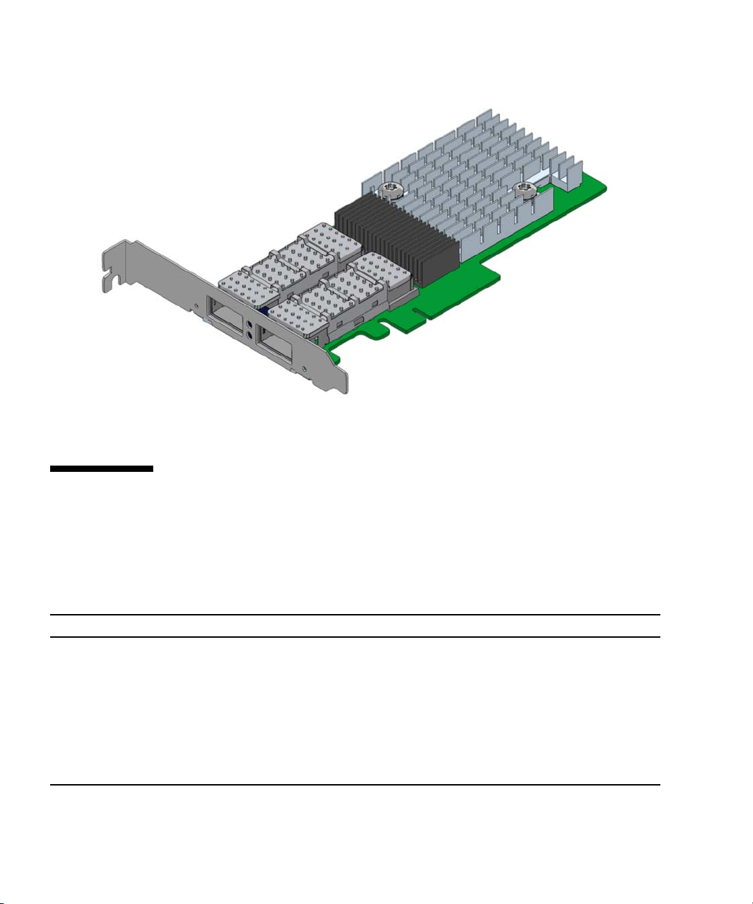
FIGURE 1-1 Sun x8 Express Dual 10 Gigabit Ethernet Fiber XFP Low Profile Adapter
Hardware and Software Requirements
Before installing the adapter, make sure your system meets the hardware and
software requirements.
TABLE 1-1 Hardware and Software Requirements for Sun SPARC and X64 Servers
Requirements Hardware or Software
Hardware Sun Fire™ T1000, Sun Fire T2000, Sun Fire V445, Sun Fire V245, Sun Fire
V215, Sun Fire U45, Sun Fire X4600, Sun Fire X4200, Sun Fire X4100, Sun Fire
X2100
Operating System Solaris 10 01/07 Operating System
SuSE Linux Enterprise Server 10, RedHat Enterprise Linux
4.0_u4, RedHat Enterprise Linux 4.0_u3
Optical transceivers X5558A SR (Short Reach) XFP Transceiver for the base board
X5560A-z LR (Long Reach) XFP Transceiver for the base board
TABLE 1-1 lists the supported hardware and software.
2 Sun Dual 10GbE XFP PCI Express Card User’s Guide • January 2009
Page 21

Features
The Sun x8 Express Dual 10 Gigabit Ethernet Fiber XFP Low Profile Adapter
provides the following features:
■ Two full-duplex 10 gigabit Ethernet interface that use a 10 gigabit Ethernet small
form factor pluggable (XFP), optical transceiver with duplex LC fiber connector
■ IEEE 802.3ae 2002 compliant
■ Uses Sun’s own ASIC and software for innovative throughput networking design
■ Networking I/O virtualization supporting Solaris LDOM 1.0. (VMware support
planned for mid 07)
■ Hardware-based flow classification for extending parallelism and virtualization to
networking
■ Up to 16 Receive DMA channels and up to 24 Transmit DMA channels, multiple
receive and transmit Descriptor Rings and dedicated networking hardware
resources (DMA, interrupts, buffer, and more) for each thread or strand
■ CPU/thread affinity and CPU load balancing at L1,L2,L3 and L4
■ Dynamic Reconfiguration (DR)
■ Jumbo frame support (up to 9KBytes)
■ IPv4/IPv6 and IPMP support
■ TCP/UDP/IP checksum and CRC32C support
■ IEEE 802.1Q VLAN support
Chapter 1 Product Overview 3
Page 22

4 Sun Dual 10GbE XFP PCI Express Card User’s Guide • January 2009
Page 23

CHAPTER
2
Installing and Setting Up the Driver
This chapter explains how to download and install the nxge driver. The nxge gigabit
Ethernet driver (nxge(7D)) is a multi-threaded, loadable, clonable, GLD-based
STREAMS driver. The nxge driver is managed by the dladm(1M) command line
utility, which allows VLANs to be defined on top of nxge instances and for nxge
instances to be aggregated. See the dladm(1M) man page for more details on
configuring the data-link interfaces and link aggregations.
This chapter contains the following sections:
■ “Downloading and Installing the Driver on a Solaris SPARC or x86 Platform” on
page 5
■ “Downloading and Installing the Driver on a Linux Platform” on page 9
Downloading and Installing the Driver on a Solaris SPARC or x86 Platform
If your system uses the Solaris SPARC or x86 operating system you will need to
download and install the nxge device driver for Solaris platforms.
▼ To Download the Driver on a Solaris Platform
1. Locate and download the nxge device driver software at the following web site:
http://www.sun.com/products/networking/ethernet/index.html
5
Page 24

2. Uncompress the gzipped tar file:
# gunzip nxge.tar.gz
3. Unpack the tar file:
# tar xvf nxge.tar
a. For SPARC systems, change to the following directory:
# cd 10_GigabitEthernet/Solaris_10/sparc/Packages
b. For x86 systems:
# cd 10_GigabitEthernet/Solaris_10/i386/Packages
4. For SPARC systems, determine which architecture your system is running:
# uname -m
a. For sun4v systems, install the software packages by typing the following at the
command line:
# /usr/sbin/pkgadd -d SUNWnxge.v SUNWnxgem
b. For sun4u systems, install the software packages by typing the following at the
command line:
# /usr/sbin/pkgadd -d SUNWnxge.u SUNWnxgem
6 Sun Dual 10GbE XFP PCI Express Card User’s Guide • January 2009
Page 25
5. For x86 systems, install the software packages by typing the following at the
command line:
# /usr/sbin/pkgadd -d
A menu similar to the following displays:
The following packages are available:
1 SUNWnxge Sun PCI-E 10G/1G Ethernet Adapter Driver (i386)
1.0,REV=2006.12.05.10.0
Select package(s) you wish to process (or ’all’ to process
all packages). (default: all) [?,??,q]:
6. Select the packages you want to install:
■ Press Return or type all to accept the default and install all packages.
■ Type the specific numbers, separated by a space, if you prefer not to install any
optional packages.
Chapter 2 Installing and Setting Up the Driver 7
Page 26

7. Verify that the nxge driver is installed on the system:
Sun PCI-E 10G/1G Ethernet Adapter Driver(i386)
1.0,REV=2006.12.05.10.0 Copyright 2006 Sun Microsystems,
Inc. All rights reserved. Use is subject to license terms.
## Executing checkinstall script. Using as the package base directory.
## Processing package information.
## Processing system information.
4 package pathnames are already properly installed.
## Verifying package dependencies.
## Verifying disk space requirements.
## Checking for conflicts with packages already installed.
## Checking for setuid/setgid programs. This package contains
scripts which will be executed with super-user permission
during the process of installing this package.
Do you want to continue with the installation of [y,n,?] y
Installing Sun PCI-E 10G/1G Ethernet Adapter Driver as
## Installing part 1 of 1.
/kernel/drv/amd64/nxge [ verifying class ]
# Executing postinstall script.
# Installation of was successful.
▼ To Remove the Driver from a Solaris Platform
1. To discover the driver packages run the pkginfo command:
# pkginfo | grep SUNWnxge
SUNWnxge Sun PCI-E 10G/1G Ethernet Adapter Driver
2. To remove the driver packages run the pkgrm command:
# pkgrm SUNWnxge plus any other packages from the previous command
8 Sun Dual 10GbE XFP PCI Express Card User’s Guide • January 2009
Page 27

Downloading and Installing the Driver on a Linux Platform
1. Login to your system.
2. Download the driver RPM for your operating system:
http://www.sun.com/download/products.xml?id=44eb1efd
For example:
nxge-1.0-1.x86_64.rpm
3. Discover the network interfaces before adding the package by using the
ifconfig -a command:
# ifconfig -a |grep eth
eth0 Link encap:Ethernet HWaddr 00:14:4F:20:F1:DC
eth1 Link encap:Ethernet HWaddr 00:14:4F:20:F1:DD
eth2 Link encap:Ethernet HWaddr 00:14:4F:20:F1:DE
eth3 Link encap:Ethernet HWaddr 00:14:4F:20:F1:DF
4. Use the rpm tool to install the driver on SuSe and RedHat Linux.
# rpm -ivh /tmp/RHEL4U4-large/RPMS/x86_64/nxge-1.0-1.x86_64.rpm
Preparing... ###########################################
1:nxge ###########################################
Chapter 2 Installing and Setting Up the Driver 9
Page 28

Note – In RHEL5.0 and later releases, the driver is packaged in the kmod driver
binary package format. This packaging allows forward and backward driver binary
compatibility within the same flavors of RHEL5 releases. Driver packages nxge
version 2.0.0 and later are not compatible with the earlier nxge-1.x-x releases. To
upgrade from 1.x-x to 2.x.x rpm package, it is necessary to remove nxge-1.x-
x package before installing the 2.x.x package.
The RHEL5 nxge 2.x.x kmod package contains two separate packages: One for the
driver and another one for applications like nxge_config. You must install both of
the following packages:
kmod-nxge-rhel-2.0-1.x86_64.rpm (driver binary package)
nxge-apps-rhel-2.0-1.x86_64.rpm (application package)
To install the complete package, enter the following:
# rpm -ivh nxge-apps-rhel-2.0-1.x86_64.rpm kmod-nxge-rhel-2.0-1.x86_64.rpm
To ensure that the driver is loaded after the rpm installation, enter the following:
# modprobe nxge
5. Verify the new network interface instances corresponding to the Sun x8 Express
Dual 10 Gigabit Ethernet Fiber XFP Low Profile Adapter:
# ifconfig -a |grep eth
eth0 Link encap:Ethernet HWaddr 00:14:4F:20:F1:DC
eth1 Link encap:Ethernet HWaddr 00:14:4F:20:F1:DD
eth2 Link encap:Ethernet HWaddr 00:14:4F:20:F1:DE
eth3 Link encap:Ethernet HWaddr 00:14:4F:20:F1:DF
eth4 Link encap:Ethernet HWaddr 00:14:4F:6C:78:E8
eth5 Link encap:Ethernet HWaddr 00:14:4F:6C:78:E9
The Sun x8 Express Dual 10 Gigabit Ethernet Fiber XFP Low Profile Adapter
instances, eth4 and eth5, are shown in
bold italics.
6. Add the nxge interfaces to the /etc/modules.conf file to automatically load
the driver after system reboot:
alias eth4 nxge
alias eth5 nxge
10 Sun Dual 10GbE XFP PCI Express Card User’s Guide • January 2009
Page 29

7. Use the ethtool command to check the parameter configurations that apply to
the nxge driver.
(For 10G)
# ethtool -i eth4
driver: nxge
version: 2.0.1
firmware-version: 2XGF PXE1.47 FCode 3.9 07/04/24
bus-info: 0000:84:00.0
(Equivalent for 1G)
# ethtool -i eth4
driver: nxge
version: 2.0.1
firmware-version: QGC PXE1.47 FCode 3.9 07/04/24
bus-info: 0000:02:00.2
▼ To Remove the Driver From a Linux Platform
● To remove the driver packages from a Linux Platform use the rpm -e command:
# rpm -e nxge-1.0-1
Chapter 2 Installing and Setting Up the Driver 11
Page 30

12 Sun Dual 10GbE XFP PCI Express Card User’s Guide • January 2009
Page 31

CHAPTER
3
Installing the Adapter
This chapter describes how to install the Sun x8 Express Dual 10 Gigabit Ethernet
Fiber XFP Low Profile Adapter in your system and verify that it has been installed
correctly.
This chapter contains the following section:
■ “Installing the Adapter” on page 13
■ “Installing an Optical Transceiver” on page 17
■ “Verifying the Hardware Installation” on page 20
Note – If you are installing the Sun x8 Express Dual 10 Gigabit Ethernet Fiber XFP
Low Profile Adapter in a machine running either the Solaris x86 Operating System
or the Linux x86 Operating System, Dynamic Reconfiguration (DR) is not supported.
Installing the Adapter
If you are installing the Sun x8 Express Dual 10 Gigabit Ethernet Fiber XFP Low
Profile Adapter into a machine running Solaris 10, you must install the software
before you install the hardware.
The following instructions describe the basic tasks required to install the adapter.
Refer to your system installation or service manual for detailed PCI-Express adapter
installation instructions, specifically you must check which bracket your server
requires (low profile or standard height), and install the standard height bracket if
required.
Caution – Sun x8 Express Dual 10 Gigabit Ethernet Fiber XFP Low Profile Adapter
mechanical fit limitations:
Do not install the Sun x8 Express Dual 10 Gigabit Ethernet Fiber XFP Low Profile
13
Page 32

Adapter in slot-2 of a Sun Fire T2000 system. The SATA cables from the adjacent
card slot prevent the proper installation of an Sun x8 Express Dual 10 Gigabit
Ethernet Fiber XFP Low Profile Adapter in this slot. (Note that this issue does not
exist for Sun Fire T2000 that is RoHS compliant.)
Caution – Do not install the Sun x8 Express Dual 10 Gigabit Ethernet Fiber XFP
Low Profile Adapter in slot-5 of a Sun Fire X4600 system because the heatsink on the
adapter will sit against the daughter card of the Sun Fire X4600 system.
Note – When you install the adaper, ensure that the optical transceiver has not been
installed. The optical transceiver must be installed into the adapter when it is in
place.
This section contains the following topics:
■ “To Install the Adapter” on page 14
■ “Installing an Optical Transceiver” on page 17
■ “Verifying the Hardware Installation” on page 20
▼ To Install the Adapter
1. Halt and power off your system.
2. Power off all of the peripherals connected to your system.
3. Open the system unit.
4. Attach the adhesive copper strip of the antistatic wrist strap to the metal casing of
the power supply. Wrap the other end twice around your wrist, with the adhesive
side against your skin.
5. Remove the filler panel from the PCI-E opening.
14 Sun Dual 10GbE XFP PCI Express Card User’s Guide • January 2009
Page 33

Note – These illustrations show the Sun x8 Express Dual 10 Gigabit Ethernet Fiber
XFP Low Profile Adapter being installed into a Sun Fire T2000, which requires a
standard height bracket for the low profile adapter.
6. Open the retaining clip at the edge of the PCI-E opening.
7. Holding the adapter by the edges, align the adapter edge connector with the
PCI-E slot. Slide the adapter face plate into the small slot at the end of the PCI-E
opening.
8. Applying even pressure at both corners of the adapter, push the PCI-Express
adapter until it is firmly seated in the slot.
Chapter 3 Installing the Adapter 15
Page 34

9. Secure the retaining clip
Caution – Do not use excessive force when installing the adapter into the PCI-E
slot. You might damage the adapter’s PCI connector. If the adapter does not seat
properly when you apply even pressure, remove the adapter and carefully reinstall
it.
10. Detach the wrist strap and close the system unit.
16 Sun Dual 10GbE XFP PCI Express Card User’s Guide • January 2009
Page 35

11. Install the optical transceivers.
Note – Illustrations for installing the adapter and installing the optical transceiver
show different systems. This difference in systems provides the maximum clarity for
installing the optical tranceiver and shows the most complicated adapter
installation.
Installing an Optical Transceiver
The Sun x8 Express Dual 10 Gigabit Ethernet Fiber XFP Low Profile Adapter
requires an optical transceiver in each port to create and Ethernet connection. The
short-range optical transceiver Part Number: 135-1172-01 and the long-range optical
transceiver Part Number: 375-3495-01 are both available from Sun Microsystems.
Chapter 3 Installing the Adapter 17
Page 36

▼ To Install an Optical Transceiver
1. Pull the white locking handle into the full horizontal position.
You will feel the handle click into position when it is fully opened.
Note – If you are installing an optical transceiver in a SunFire T1000, ensure that the
label and the edge connector is visible to you.
2. Holding the optical transceiver by the edges, align the transceiver with the slot in
the Sun x8 Express Dual 10 Gigabit Ethernet Fiber XFP Low Profile Adapter and
slide it into the opening.
3. Applying even pressure at both corners of the transceiver, push the transceiver
until it is firmly seated in the slot.
18 Sun Dual 10GbE XFP PCI Express Card User’s Guide • January 2009
Page 37

4. Push the handle closed to lock the optical transceiver in place.
5. Repeat Step 1 through Step 4 to install the second optical transceiver
6. Detach the wrist strap.
Caution – If you pull the locking handle down when the optical transceiver is
installed, remove the optical transceiver entirely and reinstall it. The handle operates
an internal lock. Pulling the handle down can disconnect the optical transceiver,
even though it might appear to be connected.
Chapter 3 Installing the Adapter 19
Page 38

7. Connect the Ethernet cables.
Verifying the Hardware Installation
After you have installed the Sun 10-Gigabit Ethernet adapter, but before you boot
your system, perform the following tasks to verify the installation. Refer to the your
Solaris documentation for the detailed instructions.
Note – Verification is not required if your system supports dynamic reconfiguration
(DR). Verification is not supported if your system is running Solaris x86 software.
▼ To Verify the Hardware Installation
1. Power on the system, and when the banner appears, press the Stop-A key
sequence to interrupt the boot process and display the OpenBoot (ok) prompt.
2. List the network devices on your system.
ok show-nets
a) /pci@7c0/pci@0/pci@8/network@0,1
b) /pci@7c0/pci@0/pci@8/network@0
c) /pci@7c0/pci@0/pci@2/network@0,1
d) /pci@7c0/pci@0/pci@2/network@0
e) /pci@780/pci@0/pci@1/network@0,1
f) /pci@780/pci@0/pci@1/network@0
q) NO SELECTION from the above list
Checking the .properties output for each device is the surest way to identify the
device. Usually /pci@7c0/pci@0/pci@8 or /pci@7c0/pci@0/pci@9 correspond
to PCIe slots, so look at those devices first.
a) /pci@7c0/pci@0/pci@8/network@0,1
b) /pci@7c0/pci@0/pci@8/network@0
Note – If you do not see the device listed, check that the adapter is properly seated.
If necessary, reinstall the adapter.
20 Sun Dual 10GbE XFP PCI Express Card User’s Guide • January 2009
Page 39

3. View the device that you installed.
Using the previous example, type:
ok cd /pci@7c0/pci@0/pci@8/network@0,1
4. Use the .properties command to display a list of device properties.
The .properties command displays the specific information about the device. If
you are using the Sun x8 Express Dual 10 Gigabit Ethernet Fiber XFP Low Profile
Adapter, your output will be similar to the following:
ok .properties
assigned-addresses 82080010 00000000 04000000 00000000 01000000
82080018 00000000 03500000 00000000 00008000
82080020 00000000 03508000 00000000 00008000
82080030 00000000 03600000 00000000 00100000
local-mac-address 00 14 4f 6b ce 88
phy-type xgf
reg 00080000 00000000 00000000 00000000 00000000
03080010 00000000 00000000 00000000 01000000
03080018 00000000 00000000 00000000 00008000
03080020 00000000 00000000 00000000 00008000
03080030 00000000 00000000 00000000 00100000
version 2XGF 10G Ethernet Adapter FCode 1.26 06/11/14
board-model 501-7283-04
model SUNW,pcie-2xgf
compatible pciex108e,abcd.108e.0.0
pciex108e,abcd.108e.0
pciex108e,abcd.0
pciex108e,abcd
pciexclass,020000
pciexclass,0200
pci108e,abcd
address-bits 00000030
max-frame-size 00002400
network-interface-type ethernet
device_type network
name network
fcode-rom-offset 00000000
interrupts 00000001
class-code 00020000
subsystem-vendor-id 0000108e
revision-id 00000000
device-id 0000abcd
vendor-id 0000108e
Chapter 3 Installing the Adapter 21
Page 40

5. Type the following when you finish looking at the .properties values:
ok device-end
Rebooting the System
After verifying the adapter installation, use the boot -r command to perform a
reconfiguration boot on your system.
ok boot -r
22 Sun Dual 10GbE XFP PCI Express Card User’s Guide • January 2009
Page 41

CHAPTER
4
Network Configuration
This chapter describes how to edit the network host files after the adapter has been
installed on your system. This chapter contains the following sections:
■ “Configuring the Network Host Files” on page 23
■ “Setting Up a 10-Gigabit Ethernet Network on a Diskless Client System” on
page 25
■ “Installing the Solaris Operating System Over a 10-Gigabit Ethernet Network” on
page 27
■ “Booting Over the 10-Gigabit Ethernet Network for Solaris x86 and Linux
Systems” on page 31
Configuring the Network Host Files
After installing the driver software, you must create a hostname.nxgenumber file
for the adapter’s Ethernet interface. You must also create both an IP address and a
host name for its Ethernet interface in the /etc/hosts file.
23
Page 42

1. At the command line, use the grep command to search the /etc/path_to_inst
file for nxge interfaces.
# grep nxge /etc/path_to_inst
# "/pci@7c0/pci@0/pci@9/network@0" 0 "nxge"
# "/pci@7c0/pci@0/pci@9/network@0,1" 1 "nxge"
#
In this example, the device instance is from a Sun x8 Express Dual 10 Gigabit
Ethernet Fiber XFP Low Profile Adapter installed in slot 1.
Be sure to write down your device path and instance, which in the example is
"/pci@7c0/pci@0/pci@9/network@0" 0. Your device path and instance will be
similar. You need this information to make changes to the nxge.conf file. See
“Setting Parameters Using the nxge.conf File” on page 38.
2. Use the ifconfig command to set up the adapter’s nxge interface.
Use the ifconfig command to assign an IP address to the network interface.
Type the following at the command line, replacing ip-address with the adapter ’s IP
address:
# ifconfig nxge0 plumb ip-address up
Refer to the ifconfig(1M) man page and the Solaris documentation for more
information.
■ If you want a setup that remains the same after you reboot, create an
/etc/hostname.nxgenumber file, where number is the instance number of the
nxge interface you plan to use.
To use the adapter ’s nxge interface in the Step 1 example, create an
/etc/hostname.nxge0 file, where 0 is the number of the nxge interface. If the
instance number were 1, the filename would be
/etc/hostname.nxge1.
■ Do not create an /etc/hostname.nxgenumber file for a Sun x8 Express Dual 10
Gigabit Ethernet Fiber XFP Low Profile Adapter interface you plan to leave
unused.
■ The /etc/hostname.nxgenumber file must contain the host name for the
appropriate nxge interface.
■ The host name must have an IP address listed in the /etc/hosts file.
24 Sun Dual 10GbE XFP PCI Express Card User’s Guide • January 2009
Page 43

■ The host name must be different from any other host name of any other interface,
for example: /etc/hostname.nxge0 and /etc/hostname.nxge1 cannot share
the same host name.
The following example shows the /etc/hostname.nxgenumber file required for a
system called zardoz that has a Sun x4 PCI-Express Gigabit Ethernet driver
(zardoz-11).
# cat /etc/hostname.nxge0
zardoz
# cat /etc/hostname.nxge1
zardoz-11
3. Create an appropriate entry in the /etc/hosts file for each active nxge interface.
For example:
# cat /etc/hosts
#
# Internet host table
#
127.0.0.1 localhost
129.144.10.57 zardoz loghost
129.144.11.83 zardoz-11
Setting Up a 10-Gigabit Ethernet Network on a Diskless Client System
Before you can boot and operate a diskless client system across a 10-Gigabit Ethernet
network, you must first install the 10-Gigabit Ethernet software packages into the
root directory of the diskless client. You can find the 10-Gigabit Ethernet software
packages at the following web site:
http://www.sun.com/download/index.jsp?cat=Networking&tab=
3&subcat=Network%20Connectivity
Refer to the Solaris Advanced Installation Guide and the System Administration Guide
for more information about installing and administering diskless client systems.
Note – The Solaris x86 version of the operating system do not support diskless
clients.
Chapter 4 Network Configuration 25
Page 44

▼ To Set Up a 10-Gigabit Ethernet Port on a
Diskless Client
1. Locate the root directory of the diskless client on the host server.
The root directory of diskless client system is commonly installed in the host
server’s /export/root/client-name directory, where client_name is the diskless
client’s host name. In this procedure, the root directory is:
/export/root/client-name
2. Download the software for Sun x8 Express Dual 10 Gigabit Ethernet Fiber XFP
Low Profile Adapter onto the server’s drive.
3. Use the pkgadd -R command to install the software packages to the diskless
client’s root directory on the server.
Install the software packages to the client’s root directory.
4. Create a hostname.nxgenumber file in the diskless client’s root directory.
Create an /export/root/client-name/etc/hostname.nxgenumber file for the 10Gigabit Ethernet interface. See “Configuring the Network Host Files” on page 23 for
instructions.
5. Edit the hosts file in the diskless client’s root directory.
Edit the /export/root/client-name/etc/hosts file to include the IP address of
the 10-Gigabit Ethernet interface. See “Configuring the Network Host Files” on
page 23 for instructions.
6. Set the MAC address on the server side and rebuild the device tree if you want to
boot from the 10-Gigabit Ethernet port.
7. To boot the diskless client from the 10-Gigabit Ethernet port, type the following
boot command:
ok boot path-to-device:link-param
26 Sun Dual 10GbE XFP PCI Express Card User’s Guide • January 2009
Page 45

Installing the Solaris Operating System Over a 10-Gigabit Ethernet Network
The Solaris Advanced Installation Guide describes the full procedure for installing the
Solaris Operating System over the network. The following procedure assumes that
you have created an install server, which contains the image of the Solaris CD, and
that you have set up the client system to be installed over the network.
Before you can install the Solaris Operating System on a client system with a 10Gigabit Ethernet adapter, you must first add the 10-Gigabit Ethernet software
packages to the install server. These software packages are on Sun 10-Gigabit
Ethernet Driver CD.
Note – Refer to the Solaris Advanced Installation Guide for more information about
installing the Solaris Operating System over the network.
▼ To Install the Solaris Operating System Over a
10-Gigabit Ethernet Network
1. Prepare the install server and client system to install the Solaris Operating System
over the network.
The Solaris Advanced Installation Guide describes how to create the install server and
set up the client systems.
Note – If you want to install the client system over a network that is not part of the
same subnet, you must also create a boot server. The Solaris Advanced Installation
Guide describes how to create a boot server.
Chapter 4 Network Configuration 27
Page 46

2. Find the root directory of the client system.
The client system’s root directory can be found in the install server’s
/etc/bootparams file. Use the grep command to search this file for the root
directory.
# grep client-name /etc/bootparams
client_name root=server-name:/netinstall/Solaris_10/Tools/Boot
install=server-name:/netinstall boottype=:in rootopts=:rsize=32768
In this example, the root directory for the Solaris 10 client is /netinstall.In
Step 4, you would replace root-directory with /netinstall.
Note – If the root directory is not found in the /etc/bootparams file, refer to the
Solaris Advanced Installation Guide for configuration instructions.
3. Download the Sun x8 Express Dual 10 Gigabit Ethernet driver onto the install
server’s hard drive.
The package is a folder SUNWnxge.v or SUNWnxge.u, which you can download
from the following web site:
http://www.sun.com/download/products.xml?id=44eb1efd
4. On the install server, install the Sun x8 Express Dual 10 Gigabit Ethernet software
to the client’s root directory, as determined in Step 2.
Replace root-directory with the location of the client’s root directory.
# cd location where you downloaded the packages
# ls SUNWnxge*
# pkgadd -R root-directory/Solaris_10/Tools/Boot -d . SUNWnxge.v
Note – If the commands above do not work correctly, refer to the documentation for
your version of the Solaris Operating System.
Note – Perform the following steps on the client system.
28 Sun Dual 10GbE XFP PCI Express Card User’s Guide • January 2009
Page 47

5. Shut down and halt the client system.
Use the shutdown command to go to the OpenBoot (ok) prompt.
# shutdown -i0 -g0 -y
. . .
(shutdown command messages omitted)
. . .
ok
6. At the ok prompt, use the show-nets command to find the device path of the 10-
Gigabit Ethernet device.
The show-nets command lists the system devices. You should see the full paths
and names of the network devices, similar to the example below.
ok show-nets
a) /pci@7c0/pci@0/pci@8/network@0,1
b) /pci@7c0/pci@0/pci@8/network@0
c) /pci@7c0/pci@0/pci@2/network@0,1
d) /pci@7c0/pci@0/pci@2/network@0
e) /pci@780/pci@0/pci@1/network@0,1
f) /pci@780/pci@0/pci@1/network@0
q) NO SELECTION from the above list
7. At the ok prompt, boot the client system using the full device path of the 10-
Gigabit Ethernet device, for example:
ok boot /pci@7c0/pci@0/pci@8/network@0
8. Proceed with the Solaris Operating System installation.
Refer to the Solaris Advanced Installation Guide for more information about installing
the Solaris Operating System over the network.
Chapter 4 Network Configuration 29
Page 48

9. After installing the Solaris Operating System, install the Sun x8 Dual 10 Gigabit
Ethernet software on the client system.
The software installed in Step 4 is required to boot the client system over the 10Gigabit Ethernet interface. You now need to install the software in order for the
operating system to use the client’s 10-Gigabit Ethernet interfaces in normal
operation.
Before installing the Sun 10-Gigabit Ethernet driver, ensure that the client system
does not already have the driver installed. Use the pkginfo command to see if the
Sun 10-Gigabit Ethernet software packages are installed on the client system.
# pkginfo | grep SUNWnxge
■ If the software is installed, the previous command will return the package name
you typed in. In that case, skip to Step 10.
■ If the software is not installed, install the software from the download center.
See Chapter 2 for instructions on installing the required software packages.
10. Confirm that the network host files have been configured correctly during the
Solaris installation.
Although the Solaris software installation creates the client’s network configuration
files, you may need to edit these files to match your specific networking
environment. See “Configuring the Network Host Files” on page 23 for more
information about editing these files.
11. Use the dladm show-dev command to show configuration information for all
data-links or the specified data-link. By default, the system is configured to
have one data-link for each known network device.
# dladm show-dev
e1000g0 link: up speed: 1000 Mbps duplex: full
e1000g1 link: down speed: 0 Mbps duplex: half
e1000g2 link: down speed: 0 Mbps duplex: half
e1000g3 link: down speed: 0 Mbps duplex: half
nxge0 link: up speed: 10000 Mbps duplex: full
nxge1 link: up speed: 10000 Mbps duplex: full
30 Sun Dual 10GbE XFP PCI Express Card User’s Guide • January 2009
Page 49

Booting Over the 10-Gigabit Ethernet Network for Solaris x86 and Linux Systems
▼ To Boot Over the Network on Solaris x86 and
Linux Systems
1. Obtain the MAC address from the target Sun x8 Express Dual 10 Gigabit Ethernet
Fiber XFP Low Profile Adapter.
2. Set up the PXE boot server with the MAC addresses .
3. Choose one of the adapter ports as the boot interface.
4. Plug the Ethernet cable to the adapter port.
5. Power on the system.
6. Press the F2 key or the Control/E keys to go to the BIOS.
7. Check and make sure that the boot order of Hard Drive is higher than network
devices.
8. Refer the boot-device-order image.
The reconfiguration boot attaches the driver to the adapter. You can now configure
the driver parameters for your Sun x8 Express Dual 10 Gigabit Ethernet Fiber XFP
Low Profile Adapter.
Chapter 4 Network Configuration 31
Page 50

9. Press the F10 key to save the boot configuration changes and exit.
System should reboot after saving the boot configuration.
32 Sun Dual 10GbE XFP PCI Express Card User’s Guide • January 2009
Page 51

10. Press the F12 key to install the OS from the network.
If the cable is connected to the right port, you should see the MAC address that you
assigned to your PXE server displayed by BIOS.
image : pxe-mac-addr
PXE-E61: Media test failure, check cable
PXE-MOF: Exiting Intel Boot Agent.
NVIDIA Boot Agent 217.0513
Copyright (C) 2001-2005) NVIDIA Corporation
Copyright (C) 1997-2000) NVIDIA Corporation
PXE-E61: Media test failure, check cable
PXE-MOF: Exiting Intel Boot Agent.
NVIDIA Boot Agent 217.0513
Copyright (C) 2001-2005) NVIDIA Corporation
Copyright (C) 1997-2000) NVIDIA Corporation
PXE-E61: Media test failure, check cable
PXE-MOF: Exiting Intel Boot Agent.
Intel (R) Boot Agent GE v1.2.43 Beta-1
Copyright (C) 1997-2006) Intel Corporation
CLIENT MAC ADDR; 00 15 17 13 90 00 GUID: 00000000 0000 0000 0000
00144F26E0B7
11. You can now install the nxge driver and configure the adapter.
Chapter 4 Network Configuration 33
Page 52

34 Sun Dual 10GbE XFP PCI Express Card User’s Guide • January 2009
Page 53

CHAPTER
5
Configuring the nxge Device Driver Parameters
The nxge device driver controls the Sun x8 Express Dual 10 Gigabit Ethernet
interfaces. You can manually set the nxge driver parameters to customize each
device in your system.
This chapter lists the available device driver parameters and describes how you can
set these parameters.
■ “nxge Hardware and Software Overview” on page 35
■ “Setting nxge Driver Parameters on a Solaris Platform” on page 36
■ “Setting Parameters Using the ndd Utility” on page 36
■ “Setting Parameters Using the nxge.conf File” on page 38
■ “Setting Parameters on a Linux Platform” on page 46
nxge Hardware and Software Overview
The Sun x8 Express Dual 10 Gigabit Ethernet Fiber XFP Low Profile Adapter
provides two 10-Gigabit Full Duplex networking interfaces. The device driver
automatically sets the link speed to 10000 Mbit/sec and conforms to the IEEE 802.3
Ethernet standard. Each interface has 8 Receive DMA Channels and 12 Transmit
DMA Channels to allow for parallel processing of the packets. The Sun x8 Express
Dual 10 Gigabit Ethernet Fiber XFP Low Profile Adapter extends CPU and OS
parallelism to networking with its support for hardware-based flow classification
and multiple DMAs. Using CPU thread affinity to bind a given flow to a specific
CPU thread, it enables a one-to-one correlation of Rx and Tx packets across the same
TCP connection. This can help avoid cross-calls and context switching to deliver
greater performance while reducing the need for CPU resources to support I/O
35
Page 54

processing. The Sun 10-Gigabit Ethernet Adapter utilizes Sun’s own innovative
MAC Controller to map the 10-Gigabit XAUI interface onto the PCI Express form
factor. It supports 10 Gb/sec bandwidth using eight transmit and eight receive lanes.
Setting nxge Driver Parameters on a Solaris Platform
You can set the nxge device driver parameters in two ways:
■ Using the ndd utility
■ Using the nxge.conf file
If you use the ndd utility, the parameters are valid only until you reboot the system.
This method is good for testing parameter settings.
To set parameters so they remain in effect after you reboot the system, create a
/platform/sun4u/kernel/drv/nxge.conf file and add parameter values to this
file when you need to set a particular parameter for a device in the system.
Setting Parameters Using the ndd Utility
Use the ndd utility to configure parameters that are valid until you reboot the
system.
The following sections describe how you can use the nxge driver and the ndd utility
to modify (with the -set option) or display (without the -set option) the
parameters for each nxge device.
Noninteractive and Interactive Modes
You can use the ndd utility in two modes:
■ Noninteractive
■ Interactive
In noninteractive mode, you invoke the utility to execute a specific command. Once
the command is executed, you exit the utility. In interactive mode, you can use the
utility to get or set more than one parameter value. Refer to the ndd(1M) man page
for more information.
36 Sun Dual 10GbE XFP PCI Express Card User’s Guide • January 2009
Page 55

▼ To Specify Device Instances for the ndd Utility
Before you use the ndd utility to get or set a parameter for a nxge device, you must
specify the device instance for the utility.
1. Check the /etc/path_to_inst file to identify the instance associated with a
particular device.
# grep nxge /etc/path_to_inst
"/pci@7c0/pci@0/pci@9/network@0" 0 "nxge"
"/pci@7c0/pci@0/pci@9/network@0,1" 1 "nxge"
▼ To Specify Parameter Values Using the ndd
Utility
This section describes how to modify and display parameter values.
1. To modify a parameter value, use the -set option.
If you invoke the ndd utility with the -set option, the utility passes value, which
must be specified, down to the named /dev/nxgedriver_instance, and assigns the
value to the parameter:
# ndd -set /dev/nxgeX parameter-value
Where X is the driver instance, for example /dev/nxge0, /dev/nxge1.
2. To display the value of a parameter, specify the parameter name and omit the
value.
When you omit the -set option, the utility queries the named driver instance,
retrieves the value associated with the specified parameter, and prints it:
# ndd /dev/nxgeX parameter
▼ To Use the ndd Utility in Interactive Mode
1. To modify a parameter value in interactive mode, specify ndd /dev/nxgeX:
# ndd /dev/nxge0
name to get/set? (Enter the parameter name or ? to view all
parameters)
Chapter 5 Configuring the nxge Device Driver Parameters 37
Page 56

After you enter the parameter name, the ndd utility prompts you for the parameter
value.
2. To list all the parameters supported by the nxge driver, type ?.
# ndd /dev/nxge1 name to get/set ?
? (read only)
function_number (read only)
adv_autoneg_cap (read and write)
adv_10gfdx_cap (read and write)
adv_1000fdx_cap (read and write)
adv_100fdx_cap (read and write)
adv_10fdx_cap (read and write)
adv_pause_cap (read and write)
accept_jumbo (read and write)
rxdma_intr_time (read and write)
rxdma_intr_pkts (read and write)
class_opt_ipv4_tcp (read and write)
class_opt_ipv4_udp (read and write)
class_opt_ipv4_ah (read and write)
class_opt_ipv4_sctp (read and write)
class_opt_ipv6_tcp (read and write)
class_opt_ipv6_udp (read and write)
class_opt_ipv6_ah (read and write)
class_opt_ipv6_sctp (read and write)
Setting Parameters Using the nxge.conf File
Specify the driver parameter properties for each device by creating a nxge.conf file
in the /kernel/drv directory. Use a nxge.conf file when you need to set a
particular parameter for a device in the system.
The man pages for prtconf(1M) and driver.conf(4) include additional details.
The next procedure shows an example of setting parameters in a nxge.conf file.
● To access any man page, type the man command plus the name of the man page.
For example, to access man pages for prtconf(1M), type:
% man prtconf
38 Sun Dual 10GbE XFP PCI Express Card User’s Guide • January 2009
Page 57

▼ To Set Driver Parameters Using an nxge.conf
File
1. Obtain the hardware path names for the nxge devices in the device tree.
a. Check the /etc/driver_aliases file to identify the name associated with a
particular device:
# grep nxge /etc/driver_aliases
nxge "pciex108e,abcd"
b. Locate the path names and the associated instance numbers in the
/etc/path_to_inst file.
# grep nxge/etc/path_to_inst
"/pci@780/pci@0/pci@8/network@0" 0 "nxge"
"/pci@780/pci@0/pci@8/network@0,1" 1 "nxge"
■ In this example:
■ The first part within the double quotes specifies the hardware node name in
the device tree.
■ The number not enclosed in quotes is the instance number (shown in bold
italics
■ The last part in double quotes is the driver name.
for emphasis).
To identify a PCI-E device unambiguously in the nxge.conf file, use the name,
parent name, and the unit-address for the device. Refer to the pci(4) man page for
more information about the PCI-E device specification.
In this example:
■ name = "pciex108e,abcd"
■ parent = "/pci@780/pci@0/pci@8/network@0"
■ unit-address = "0"
2. Set the parameters for the nxge devices in the
/platform/sun4u/kernel/drv/nxge.conf file.
a. The following parameters can be set using the
/platform/sun4u/kernel/drv/nxge.conf file.
#
#---------------Link Configuration ---------------------# The link parameters depend on the type of the card
# and the port.
# 10 gigabit related parameters ( i.e adv_10gfdx_cap)
Chapter 5 Configuring the nxge Device Driver Parameters 39
Page 58

# apply only to 10gigabit ports.
# Half duplex is not supported on any NIU card.
#
# adv-autoneg-cap
# Advertise auto-negotiation capability.
# default is 1
# adv-autoneg-cap = 1;
#
# adv_10gfdx_cap
# Advertise 10gbps Full duplex capability.
# default is 1
# adv_10gfdx_cap = 1;
#
# adv_1000fdx_cap
# Advertise 1gbps Full duplex capability.
# default is 1
# adv_1000fdx_cap = 1;
#
# adv_100fdx_cap
# Advertise 100mbps Full duplex capability.
# default is 1
# adv_100fdx_cap = 1;
#
# adv_10fdx_cap
# Advertise 10mbps Full duplex capability.
# default is 1
# adv_10fdx_cap = 1;
#
# adv_asmpause_cap
# Advertise Asymmetric pause capability.
# default is 0
# adv_asmpause_cap = 0;
#
# adv_pause_cap
# Advertise pause capability.
# default is 1
# adv_pause_cap = 1;
#
#
#------- Jumbo frame support --------------------------------# To enable jumbo support for all nxge interfaces,
# accept_jumbo = 1;
#
# To disable jumbo support for all nxge interfaces,
# accept_jumbo = 0;
#
# Default is 0. See the example at the end of this file for
# enabling or disabling jumbo for a particular nxge interface.
#
40 Sun Dual 10GbE XFP PCI Express Card User’s Guide • January 2009
Page 59

#
#------- Receive DMA Configuration ---------------------------#
# rxdma-intr-time
# Interrupts after this number of NIU hardware ticks have
# elapsed since the last packet was received.
# A value of zero means no time blanking (Default = 8).
#
# rxdma-intr-pkts
# Interrupt after this number of packets have arrived since
# the last packet was serviced. A value of zero indicates
# no packet blanking (Default = 20).
#
# Default Interrupt Blanking parameters.
#
# rxdma-intr-time = 8;
# rxdma-intr-pkts = 20;
#
#
#------- Classification and Load Distribution Configuration -----#
# class-opt-****-***
# These variables define how each IP class is configured.
# Configuration options range from whether TCAM lookup ie
# is enabled to flow hash generation.
# This parameters also control how the flow template is
# constructed and how packet is distributed within RDC
# groups.
#
# supported classes:
# class-opt-ipv4-tcp class-opt-ipv4-udp class-opt-ipv4-sctp
# class-opt-ipv4-ah class-opt-ipv6-tcp class-opt-ipv6-udp
# class-opt-ipv6-sctp class-opt-ipv6-ah
#
# Configuration bits (The following bits will be decoded
# by the driver as hex format).
#
# 0010: use MAC Port (for flow key)
# 0020: use L2DA (for flow key)
# 0040: use VLAN (for flow key)
# 0080: use proto (for flow key)
# 0100: use IP src addr (for flow key)
# 0200: use IP dest addr (for flow key)
# 0400: use Src Port (for flow key)
# 0800: use Dest Port (for flow key)
#
# class-opt-ipv4-tcp = fe0;
#
Chapter 5 Configuring the nxge Device Driver Parameters 41
Page 60

b. The following parameters operate on a per port basis and can be set using the
/platform/sun4u/kernel/drv/nxge.conf file.
#
# ------- How to set parameters for a particular interface -------# The example below shows how to locate the device path and set a
# parameter for a particular nxge interface. (Using jumbo support as
# an example)
#
# Use the following command to find out the device paths for nxge,
# more /etc/path_to_inst | grep nxge
#
# For example, if you see,
# "/pci@7c0/pci@0/pci@8/network@0" 0 "nxge"
# "/pci@7c0/pci@0/pci@8/network@0,1" 1 "nxge"
# "/pci@7c0/pci@0/pci@8/network@0,2" 2 "nxge"
# "/pci@7c0/pci@0/pci@8/network@0,3" 3 "nxge"
#
# then you can enable jumbo for ports 0 and 1 and disable jumbo for ports 2
# and 3 as follows,
#
# name = "pciex108e,abcd" parent = "/pci@7c0/pci@0/pci@8/" unit-address
= "0"
# accept_jumbo = 1;
# name = "pciex108e,abcd" parent = "/pci@7c0/pci@0/pci@8/" unit-address
= "0,1"
# accept_jumbo = 1;
# name = "pciex108e,abcd" parent = "/pci@7c0/pci@0/pci@8/" unit-address
= "0,2"
# accept_jumbo = 0;
# name = "pciex108e,abcd" parent = "/pci@7c0/pci@0/pci@8/" unit-address
= "0,3"
# accept_jumbo = 0;
c. In the following example, the ports of all the Sun x8 Express Dual 10 Gigabit
Ethernet Fiber XFP Low Profile Adapter are being set for load balancing Rx
traffic based on IP source address. The default value is F80 indicating Rx load
balancing based on IP 5-tuple. Notice the semi-colon at the end of the last
parameter.
class-opt-ipv4-tcp = 100;
class-opt-ipv4-udp = 100;
42 Sun Dual 10GbE XFP PCI Express Card User’s Guide • January 2009
Page 61

d. The following example shows ports on two different cards being set. Only one
node needs to be specified.
name = "pciex108e,abcd" parent = "/pci@780/pci@0/pci@8/" unit-address = "0"
class-opt-ipv4-tcp = 0x100;
name = "pciex108e,abcd" parent = "/pci@7c0/pci@0/pci@9/" unit-address = "0"
class-opt-ipv4-tcp = 0x40;
3. Save the nxge.conf file.
Tuning for Maximum Performance on a
Solaris Platform
Tuning for maximum performance in a Solaris platform depends on whether you are
using an UltraSPARC CPU based platform or an AMD CPU based platform.
▼ To Improve Performance on an UltraSPARC
CPU Based Sun Platform
1. Improve performance by adding the following /etc/system file:
# set ddi_msix_alloc_limit=4
Increasing the MSI improves the Rx performance. The default value for MSI is 2, but
changing it to 4 improves performance (8 can be used for UltraSparc-T1 based
systems).
2. Reboot the system:
# reboot -r
Chapter 5 Configuring the nxge Device Driver Parameters 43
Page 62

3. Add the following to a startup script, or use ndd before plumbing the interface:
# ndd -set /dev/ip ip_soft_rings_cnt 8
Utilizing more soft-rings provided by the Solaris TCP/IP stack significantly
improves bulk throughput for Rx. The default number of soft-rings is 2, but
changing it to 8 improves performance. (You can increase the number to 16 in
UltraSparc-T1 based systems).
▼ To Improve Performance on an AMD CPU Based
Sun Platform
1. Enable soft-rings and change to a higher value than the default of 2 by adding the
following to the /etc/system file:
set ip:ip_squeue_fanout=1
set ip_squeue_soft_ring=1
Bulk throughput for Rx can be significantly improved by utilizing more soft-rings
provided by the Solaris TCP/IP stack. Soft-rings are disabled by default in previous
and current releases of the Solaris-x86 Operating System.
2. Reboot the system:
# reboot -r
3. Set the MSI to 1 on AMD platforms by adding following to the /etc/system file:
set ddi_msix_alloc_limit=1
4. Reboot the system:
# reboot -r
44 Sun Dual 10GbE XFP PCI Express Card User’s Guide • January 2009
Page 63

▼ To Obtain Higher Throughput Using the Generic
Tunables for the Solaris TCP/IP Stack
● To obtain higher throughput, add the following to a startup script:
ndd -set /dev/tcp tcp_conn_req_max_q 8192
ndd -set /dev/tcp tcp_conn_req_max_q0 8192
ndd -set /dev/tcp tcp_max_buf 4194304
ndd -set /dev/tcp tcp_cwnd_max 2097152
ndd -set /dev/tcp tcp_recv_hiwat 400000
ndd -set /dev/tcp tcp_xmit_hiwat 400000
Chapter 5 Configuring the nxge Device Driver Parameters 45
Page 64

Setting Parameters on a Linux Platform
▼ To Set Parameters Using the ethtool Utility
1. Determine which parameters are available using the ethtool utility:
# ethtool -help eth4
ethtool version 1.8
Usage:
ethtool DEVNAME
ethtool -a DEVNAME
ethtool -A DEVNAME \
[ autoneg on|off ] \
[ rx on|off ] \
[ tx on|off ]
ethtool -c DEVNAME
ethtool -C DEVNAME \
[adaptive-rx on|off] \
[adaptive-tx on|off] \
[rx-usecs N] \
[rx-frames N] \
[rx-usecs-irq N] \
[rx-frames-irq N] \
[tx-usecs N] \
[tx-frames N] \
[tx-usecs-irq N] \
[tx-frames-irq N] \
[stats-block-usecs N] \
[pkt-rate-low N] \
[rx-usecs-low N] \
[rx-frames-low N] \
[tx-usecs-low N] \
[tx-frames-low N] \
[pkt-rate-high N] \
[rx-usecs-high N] \
[rx-frames-high N] \
[tx-usecs-high N] \
[tx-frames-high N] \
[sample-interval N]
ethtool -g DEVNAME
46 Sun Dual 10GbE XFP PCI Express Card User’s Guide • January 2009
Page 65

ethtool -G DEVNAME \
[ rx N ] \
[ rx-mini N ] \
[ rx-jumbo N ] \
[ tx N ]
ethtool -i DEVNAME
ethtool -d DEVNAME
ethtool -e DEVNAME \
[ raw on|off ] \
[ offset N ] \
[ length N ]
ethtool -E DEVNAME \
[ magic N ] \
[ offset N ] \
[ value N ]
ethtool -k DEVNAME
ethtool -K DEVNAME \
[ rx on|off ] \
[ tx on|off ] \
[ sg on|off ] \
[ tso on|off ]
ethtool -r DEVNAME
ethtool -p DEVNAME [ %d ]
ethtool -t DEVNAME [online|(offline)]
ethtool -s DEVNAME \
[ speed 10|100|1000 ] \
[ duplex half|full ] \
[ port tp|aui|bnc|mii|fibre ] \
[ autoneg on|off ] \
[ phyad %d ] \
[ xcvr internal|external ] \
[ wol p|u|m|b|a|g|s|d... ] \
[ sopass %x:%x:%x:%x:%x:%x ] \
[ msglvl %d ]
ethtool -S DEVNAME
Chapter 5 Configuring the nxge Device Driver Parameters 47
Page 66

Following are some common parameters that can be changed:
# ethtool -c eth8
Coalesce parameters for eth8:
Adaptive RX: off TX: off
stats-block-usecs: 0
sample-interval: 0
pkt-rate-low: 0
pkt-rate-high: 0
rx-usecs: 8
rx-frames: 512
rx-usecs-irq: 0
rx-frames-irq: 512
tx-usecs: 0
tx-frames: 0
tx-usecs-irq: 0
tx-frames-irq: 0
rx-usecs-low: 0
rx-frame-low: 0
tx-usecs-low: 0
tx-frame-low: 0
rx-usecs-high: 0
rx-frame-high: 0
tx-usecs-high: 0
tx-frame-
-high: 0
rx-usecs and rx-frames control the RX interrupt rate per RX DMA channel. RX
interrupt will be generated after rx-frames have been received or after rx-usecs time
interval if fewer than rx-frames have been received within the interval. For low
latency applications, it is recommened to set rx-usecs to smaller value. For bulk
traffic, it is recommended to use larger values of rx-usecs and control the rate with
rx-frames.
rx-frames-irq controls the maximum number of rx packets processed with a single
RX interrupt.
48 Sun Dual 10GbE XFP PCI Express Card User’s Guide • January 2009
Page 67

2. To change RX interrupt Coalesce parameters use the ethtool -C command:
# ethtool -C eth4 rx-usecs 20
# ethtool -c eth4
Coalesce parameters for eth4:
Adaptive RX: off TX: off
stats-block-usecs: 0
sample-interval: 0
pkt-rate-low: 0
pkt-rate-high: 0
rx-usecs: 20
rx-frames: 512
rx-usecs-irq: 0
rx-frames-irq: 512
tx-usecs: 0
tx-frames: 0
tx-usecs-irq: 0
tx-frames-irq: 0
rx-usecs-low: 0
rx-frame-low: 0
tx-usecs-low: 0
tx-frame-low: 0
rx-usecs-high: 0
rx-frame-high: 0
tx-usecs-high: 0
tx-frame-high: 0
3. To get status of L4 HW checksumming, use the ethtool -k command:
# ethtool -k eth4
Offload parameters for eth4:
Cannot get device tcp segmentation offload settings: Operation not
supported
rx-checksumming: on
tx-checksumming: on
scatter-gather: off
tcp segmentation offload: off
Chapter 5 Configuring the nxge Device Driver Parameters 49
Page 68

▼ To Set Parameters Using the Bundled
configtool Utility
1. To get a list of tunable parameters, use the nxge_config if_name get command:
# /usr/local/bin/nxge_config eth4 get
The tunable parameters exported by this device are:
class_opt_ipv4_tcp Read-Write
class_opt_ipv4_udp Read-Write
class_opt_ipv4_ah Read-Write
class_opt_ipv4_sctp Read-Write
class_opt_ipv6_tcp Read-Write
class_opt_ipv6_udp Read-Write
class_opt_ipv6_ah Read-Write
class_opt_ipv6_sctp Read-Write
These classification variables define how each IP class is configured. This parameter
also controls how the flow template is constructed and how packets are distrubuted
within RDC groups.
Configuration bits:
0x0010: use MAC Port (for flow key)
0x0020: use L2DA (for flow key)
0x0040: use VLAN (for flow key)
0x0080: use proto (for flow key)
0x0100: use IP src addr (for flow key)
0x0200: use IP dest addr (for flow key)
0x0400: use Src Port (for flow key)
0x0800: use Dest Port (for flow key)
Note – The classification variables are modified on an adapter basis, that is, if any of
these variables is modifiied for one port, the change carries over to all other ports of
that adapter.
2. To get a particular variable use the nxge_config if_name get param_name:
# /usr/local/bin/nxge_config eth4 get class_opt_ipv4_udp
class_opt_ipv4_udp 0xfe3
50 Sun Dual 10GbE XFP PCI Express Card User’s Guide • January 2009
Page 69

3. To set a particular variable, use the /usr/local/bin/nxge_config if_name set
param_name value:
# /usr/local/bin/nxge_config eth4 set class_opt_ipv4_tcp 0xfe0
Tuning for Maximum Performance on a
Linux Platform
The following tunings will improve the performance of the Sun x8 Express Dual 10
Gigabit Ethernet device driver on a system running the Linux operating system.
1. Create the conf file (for example, sysctl_nxge.conf) that will be called by the
sysctl utility.
### IPV4 specific settings
# turns TCP timestamp support off, default 1, reduces CPU use
net.ipv4.tcp_timestamps = 0
# turn SACK support off, default on systems with a VERY fast bus ->
# memory interface this is the big gainer
net.ipv4.tcp_sack = 0
# sets min/default/max TCP read buffer, default 4096 87380 174760
net.ipv4.tcp_rmem = 10000000 10000000 10000000
# sets min/pressure/max TCP write buffer, default 4096 16384 131072
net.ipv4.tcp_wmem = 10000000 10000000 10000000
# sets min/pressure/max TCP buffer space, default 31744 32256 32768
net.ipv4.tcp_mem = 10000000 10000000 10000000
### CORE settings (mostly for socket and UDP effect)
# maximum receive socket buffer size, default 131071
net.core.rmem_max = 524287
# maximum send socket buffer size, default 131071
net.core.wmem_max = 524287
# default receive socket buffer size, default 65535
net.core.rmem_default = 524287
# default send socket buffer size, default 65535
net.core.wmem_default = 524287
# maximum amount of option memory buffers, default 10240
net.core.optmem_max = 524287
# number of unprocessed input packets before kernel starts dropping
# them, default 300
net.core.netdev_max_backlog = 300000
Chapter 5 Configuring the nxge Device Driver Parameters 51
Page 70

2. Set up the sysctl utility.
# sysctl -p /etc/sysctl_nxge.conf
52 Sun Dual 10GbE XFP PCI Express Card User’s Guide • January 2009
Page 71

CHAPTER
6
Configuring the Jumbo Frames Feature
This chapter describes how to configure the Jumbo Frames feature. It contains the
following sections:
■ “Jumbo Frames Overview” on page 53
■ “Checking Jumbo Frames Configurations” on page 53
■ “Enabling Jumbo Frames in a Solaris Environment” on page 55
■ “Enabling Jumbo Frames in a Linux Environment” on page 57
Jumbo Frames Overview
Configuring Jumbo Frames enables the Ethernet interfaces to send and receive
packets larger than the standard 1500 bytes. However, the actual transfer size
depends on the switch capability and the ethernet adapter driver capability.
Note – Refer to the documentation that came with your switch for exact commands
to configure Jumbo Frames support.
Checking Jumbo Frames Configurations
The jumbo frame configuration checking occurs at Layer 2 or Layer 3, depending on
the configuration method.
53
Page 72

▼ To Show the Driver Statistics in a Solaris
Environment
1. Use the kstat command to display driver statistics, for example:
# kstat nxge:1 |grep rdc_packets
rdc_packets 798982054
rdc_packets 792546171
rdc_packets 803941759
rdc_packets 805674872
rdc_packets 798714912
rdc_packets 799293256
rdc_packets 806470537
rdc_packets 805413540
The previous example diplays the receive packet counts on all of the eight Receive
DMA channels on interface 1. Using the kstat nxge:1 shows all the statistics that
the driver supports for that interface.
54 Sun Dual 10GbE XFP PCI Express Card User’s Guide • January 2009
Page 73

2. Use the kstat command to display driver statistics of a VLAN interface, for
example:.
# kstat nxge:38001
module: nxge instance: 38001
name: nxge38001 class: net
brdcstrcv 0
brdcstxmt 0
collisions 0
crtime 3842.493000352
ierrors 0
ifspeed 10000000000
ipackets 2116069805
ipackets64 6411037101
multircv 0
multixmt 0
norcvbuf 0
noxmtbuf 0
obytes 2757388874
obytes64 23380264381002
oerrors 0
opackets 37606022
opackets64 4332573318
rbytes 2937141290
rbytes64 47178857920554
Enabling Jumbo Frames in a Solaris Environment
This section describes how to enable jumbo frames in both a SPARC and an x86
environment.
Chapter 6 Configuring the Jumbo Frames Feature 55
Page 74

▼ To Enable Jumbo Frames in a Solaris
Environment Using nxge.conf
1. Enable Jumbo Frames for a port using the nxge.conf file. For example,
name = "pciex108e,abcd" parent = "/pci@780/pci@0/pci@8/network@0"
unit-address = "0"
accept-jumbo=1;
2. Reboot the system:
% boot -r
3. Set the maximum MTU for maximum performance:
# ifconfig nxge mtu 9194
▼ To Check Layer 2 Configuration
● View the maximum transmission unit (MTU) configuration of an nxge instance at
any time with the kstat command.
# kstat nxge:0 | grep mac_mtu
The kstat mac_mtu variable represents the complete size of the Ethernet frame,
which includes the Ethernet header, maximum payload, and crc. This value should
be equal to or less than the MTU configured on the switch.
56 Sun Dual 10GbE XFP PCI Express Card User’s Guide • January 2009
Page 75

▼ To Check Layer 3 Configuration
● Check the Layer 3 configuration by using the dladm command with the show-link
option, as shown in the following example:
# dladm show-link
e1000g0 type: non-vlan mtu: 1500 device: e1000g0
e1000g1 type: non-vlan mtu: 1500 device: e1000g1
e1000g2 type: non-vlan mtu: 1500 device: e1000g2
e1000g3 type: non-vlan mtu: 1500 device: e1000g3
nxge0 type: non-vlan mtu: 9194 device: nxge0
nxge1 type: non-vlan mtu: 9194 device: nxge1
nxge38001 type: vlan 38 mtu: 9194 device: nxge1
Enabling Jumbo Frames in a Linux Environment
This section describes how to enable jumbo frames in a Linux environment.
▼ To Enable Jumbo Frames in a Linux
Environment
1. Ensure that the nxge software is installed.
# modprobe nxge
2. Plumb the Sun x8 Express Dual 10 Gigabit Ethernet Fiber XFP Low Profile
Adapter interface:
# ifconfig eth2 xxx.xxx.xx.xxx up
where
xxx.xxx.xx.xxx is the IP address of the interface.
Chapter 6 Configuring the Jumbo Frames Feature 57
Page 76

3. Set the MTU for maximum performance:
# ifconfig ethx mtu 9194
Where x is the instance number of the interface you want to configure jumbo frames
on.
▼ To Show the Driver Statistics in a Linux
Environment
1. Use the ifconfig utility to display driver statistics, for example:
# ifconfig eth4
eth9 Link encap:Ethernet HWaddr 00:14:4F:6C:78:E9
inet addr:38.38.9.42 Bcast:38.38.9.255
Mask:255.255.255.0
inet6 addr: fe80::214:4fff:fe6c:78e9/64 Scope:Link
UP BROADCAST RUNNING MULTICAST MTU:9194 Metric:1
RX packets:748274 errors:0 dropped:0 overruns:0 frame:0
TX packets:8645339 errors:0 dropped:0 overruns:0 carrier:0
collisions:0 txqueuelen:1000
RX bytes:44983920 (42.9 MiB) TX bytes:75352303126 (70.1
GiB)
2. Use the ethtool utility with -S option to get more detailed information. This
option displays a large amount of statistics manintined by the driver.
# ethtool -S eth9 |grep rx_pac
rx_packets: 748274
rx_packets: 828
rx_packets: 112
rx_packets: 189088
rx_packets: 134
rx_packets: 196085
rx_packets: 177884
rx_packets: 93
rx_packets: 184050
58 Sun Dual 10GbE XFP PCI Express Card User’s Guide • January 2009
Page 77

3. To get more specific statitics, use the grep command on the output of ethtool -S:
# ethtool -S eth9 |grep tx_pac
tx_packets: 8645339
tx_packets: 3418334
tx_packets: 26
tx_packets: 0
tx_packets: 22
tx_packets: 401791
tx_packets: 1466540
tx_packets: 0
tx_packets: 21
tx_packets: 725
tx_packets: 3357880
tx_packets: 0
tx_packets: 0
Chapter 6 Configuring the Jumbo Frames Feature 59
Page 78

60 Sun Dual 10GbE XFP PCI Express Card User’s Guide • January 2009
Page 79

CHAPTER
7
Configuring Link Aggregation
This chapter describes how to configure link aggregation. It contains the following
sections:
■ “Overview of Link Aggregation” on page 61
■ “Configuring Link Aggregation in a Linux Environment” on page 64
Overview of Link Aggregation
Link Aggregation allows one or more network links to be aggregated together to
form a link aggregation group. This link aggregation group appears to MAC clients
as a regular link. Link aggregation is defined by IEEE 802.2ad and it provides the
following benefits:
■ Increased bandwidth
■ Linearly incremental bandwidth
■ Load sharing
■ Automatic configuration
■ Rapid configuration and reconfiguration
■ Deterministic behavior
■ Low risk of duplication or mis-ordering
■ Support of existing IEEE 802.3 MAC clients
Configuring Link Aggregation in a Solaris Environment
This section explains how to configure link aggregation in a Solaris environment.
61
Page 80

▼ To Configure Link Aggregation in a Solaris
Environment
1. Aggregate nxge0 and nxge1 to form an aggregation and a random number 33 as
key.
a. Unplumb the interfaces to be aggregated:
# ifconfig down unplumb nxge0
# ifconfig down unplumb nxge1
b. Create a link-aggregation group with key 33 without specifying mode:
# dladm create-aggr -d nxge0 -d nxge1 33
As the command returns, one line appears in /etc/aggregation.conf file and
indicates that the default mode is off, as shown in the following example:
# tail -1 /etc/aggregation.conf
33 L4 2 nxge0/0,nxge1/0 auto off short
# dladm show-aggr
key: 33 (0x0021) policy: L4 address: 0:3:ba:d8:9d:e8 (auto)
device address speed duplex link state
nxge0 0:3:ba:d8:9d:e8 10000 Mbps full up standby
nxge1 0:3:ba:d8:9d:e9 10000 Mbps full up standby
# dladm show-link aggr33
aggr33 type: non-vlan mtu: 1500 aggregation: key 33
62 Sun Dual 10GbE XFP PCI Express Card User’s Guide • January 2009
Page 81

2. Plumb up the interface aggrkey, which is aggr33 is this case:
# ifconfig aggr33 plumb
# ifconfig aggr33
aggr33: flags=1000842<BROADCAST,RUNNING,MULTICAST,IPv4> mtu 1500 index 8
inet 0.0.0.0 netmask 0
ether 0:3:ba:d8:9d:e8
# ifconfig aggr33 192.168.1.1/24 broadcast + up
# ifconfig aggr33
aggr33: flags=1000843<UP,BROADCAST,RUNNING,MULTICAST,IPv4> mtu 1500 index 8
inet 192.168.1.1 netmask ffffff00 broadcast 192.168.1.255
ether 0:3:ba:d8:9d:e8
3. Show link-aggregation status again, and now the state should become attached:
# dladm show-aggr
key: 33 (0x0021) policy: L4 address: 0:3:ba:d8:9d:e8 (auto)
device address speed duplex link state
nxge0 0:3:ba:d8:9d:e8 10000 Mbps full up attached
nxge1 0:3:ba:d8:9d:e9 10000 Mbps full up attached
4. Use the dladm show-aggr -s command to display statistics:
# dladm show-aggr -s
key: 33 ipackets rbytes opackets obytes %ipkts %opkts
Total 0 0 16 1182
nxge0 0 0 16 1182 - 100.0
nxge1 0 0 0 0 - 0.0
Chapter 7 Configuring Link Aggregation 63
Page 82

5. Use the dladm show-aggr -L command to display LACP specific information:
# dladm show-aggr -L
key: 33 (0x0021) policy: L4 address: 0:3:ba:d8:9d:e8 (auto)
LACP mode: off LACP timer: short
device activity timeout aggregatable sync coll dist defaulted expired
nxge0 passive short yes no no no no no
nxge1 passive short yes no no no no no
For more information refer to the man pages for dladm, man dladm.
Configuring Link Aggregation in a Linux Environment
This section explains how to configure link aggregation in a Linux environment.
▼ To Configure Bonding for Multiple nxge
Interfaces
1. Modify the /etc/modprobe.conf file for 2.6 kernels file by adding these lines:
alias bond0 bonding
options bonding max_bonds=2 mode=4 miimon=1000
where:
■ bond0 is the bonding device.
■ max_bonds is the number of bond interfaces to be created.
■ mode specifies the bonding policies.
■ miimon is the frequency in milliseconds that MII link monitoring will occur.
Refer to Linux documentation for more information.
2. Load the bonding driver:
# modprobe bonding
64 Sun Dual 10GbE XFP PCI Express Card User’s Guide • January 2009
Page 83

3. Configure bond0 interface.
In this example, bond0 is the master of the two interfaces eth4 and eth5.
# ip addr add 192.12.38.64/24 brd + dev bond0
# ip link set dev bond0 up
# ifenslave bond0 eth4 eth5
Chapter 7 Configuring Link Aggregation 65
Page 84

66 Sun Dual 10GbE XFP PCI Express Card User’s Guide • January 2009
Page 85

CHAPTER
8
Configuring VLANs
This chapter explains Virtual Local Area Networks (VLANs) in detail and provides
configuration instructions and examples. It contains the following sections:
■ “Overview of VLANs” on page 67
■ “Configuring VLANs in a Solaris Environment” on page 69
■ “Configuring VLANs in a Linux Environment” on page 71
With multiple VLANs on an adapter, a server with a single adapter can have a
logical presence on multiple IP subnets. By default, 128 VLANs can be defined for
each VLAN-aware adapter on your server. However, this number can be increased
by changing the system parameters.
If your network does not require multiple VLANs, you can use the default
configuration, in which case no further configuration is necessary.
Overview of VLANs
VLANs enable you to split your physical LAN into logical subparts, providing an
essential tool for increasing the efficiency and flexibility of your network.
VLANs are commonly used to separate groups of network users into manageable
broadcast domains, to create logical segmentation of workgroups, and to enforce
security policies among each logical segment. Each defined VLAN behaves as its
own separate network, with its traffic and broadcasts isolated from the others,
increasing the bandwidth efficiency within each logical group.
Although VLANs are commonly used to create individual broadcast domains
and/or separate IP subnets, it can be useful for a server to have a presence on more
than one VLAN simultaneously. Several Sun products support multiple VLANs on a
per port or per interface basis, allowing very flexible network configurations.
FIGURE 8-1 shows an example network that uses VLANs.
67
Page 86

VLAN 1
VLAN 2
VLAN 3
Shared
Media
Segment
Accounting
Server
(VLAN 3)
Main Server
Adapter
Gigabit/Tagged
(All VLANs)
Software
PC 1
(VLAN 2)
FIGURE 8-1 Example of Servers Supporting Multiple VLANs With Tagging Adapters
Software
PC 2
(VLAN 2)
Engineering
PC 3
(VLAN 1)
Accounting
PC 4
(VLAN 3)
The example network has the following features:
The physical LAN network consists of a switch, two servers, and five clients. The
LAN is logically organized into three different VLANs, each representing a different
IP subnet.
■ VLAN 1 is an IP subnet consisting of the Main Server, Client 3, and Client 5. This
represents an engineering group.
■ VLAN 2 includes the Main Server, Clients 1 and 2 by means of a shared media
segment, and Client 5. This is a software development group.
■ VLAN 3 includes the Main Server, the Accounting Server and Client 4. This is an
accounting group.
68 Sun Dual 10GbE XFP PCI Express Card User’s Guide • January 2009
Engineering/
Software PC 5
Adapter
Gigabit/Tagged
(VLAN 1 & 2)
Page 87

The Main Server is a heavily used server that needs to be accessed from all VLANs
and IP subnets. The server has a Sun x8 Express Dual 10 Gigabit Ethernet Fiber XFP
Low Profile Adapter installed. All three IP subnets are accessed by means of the
single physical adapter interface. The server is attached to one of the switch’s
Gigabit Ethernet ports, which is configured for VLANs 1, 2, and 3. Both the adapter
and the connected switch port have tagging turned on. The tagging VLAN
capabilities of both devices enable the sever to communicate on all three IP subnets
in this network, yet continue to maintain broadcast separation among the three
subnets. The following list describes the components of this network:
■ The Accounting Server is available to VLAN 3 only. It is isolated from all traffic
on VLANs 1 and 2. The switch port connected to the server has tagging turned
off.
■ Clients 1 and 2 are attached to a shared media hub that is then connected to the
switch. They belong to VLAN 2 only, and are logically in the same IP subnet as
the Main Server and Client 5. The switch port connected to this segment has
tagging turned off.
■ Client 3 is a member of VLAN 1, and can communicate only with the Main Server
and Client 5. Tagging is not enabled on Client 3’s switch port.
■ Client 4 is a member of VLAN 3, and can communicate only with the servers.
Tagging is not enabled on Client 4’s switch port.
■ Client 5 is a member of both VLANs 1 and 2, and has a Sun x8 Express Dual 10
Gigabit Ethernet Fiber XFP Low Profile Adapter installed. It is connected to
switch port 10. Both the adapter and the switch port are configured for VLANs 1
and 2 and have tagging enabled.
VLAN tagging is only required to be enabled on switch ports that create trunk links
to other VLAN-aware Ethernet switches, or on ports connected to tag-capable endstations, such as servers or workstations with VLAN-aware adapters.
Configuring VLANs in a Solaris Environment
VLANs can be created according to various criteria, but each VLAN must be
assigned a VLAN tag or VLAN ID (VID). The VID is a 12-bit identifier between 1
and 4094 that identifies a unique VLAN. For each network interface (nxge0 and
nxge1), 4094 possible VLAN IDs can be selected. Only 512 unique IDs can be used
simultaneously. Because IP subnets are commonly used, it is best to use IP subnets
when setting up a VLAN network interface. This means that each VID assigned to a
VLAN interface of a physical network interface will belong to different subnets.
Chapter 8 Configuring VLANs 69
Page 88

Tagging an Ethernet frame requires the addition of a tag header to the frame. The
header is inserted immediately following the destination MAC address and the
Source MAC address. The tag header consists of two bytes of Ethernet Tag Protocol
identifier (TPID, 0x8100) and two bytes of Tag Control Information (TCI).
FIGURE 8-2
shows the Ethernet Tag Header format.
Octet
1
2
3
4
3 bits
TPID (0x8100
1
12 bytes
bit
User_priority
FIGURE 8-2 Ethernet Tag Header Format
CFI
VID
By default, a single VLAN is configured for every port. This groups all ports into the
same broadcast domain, just as if there were no VLANs at all, VLAN tagging for the
switch port is turned off.
Note – If you configure a VLAN virtual device for an adapter, all traffic sent or
received by that adapter must be in VLAN-tagged format.
▼ To Configure Static VLANs
1. Create one hostname.nxgenumber file for each VLAN that will be configured for
each adapter on the server.
Use the following naming format, which includes both the VID and the physical
point of attachment (PPA):
VLAN logical PPA = 1000 * VID + Device PPA
nxge123000 = 1000*123 + nxge
This format limits the maximum number of PPAs (instances) you can configure to
1000 in the /etc/path_to_inst file.
For example, on a server with the Sun x8 Express Dual 10 Gigabit Ethernet Fiber
XFP Low Profile Adapter having an instance of 0, belonging to a member of two
VLANs, with VID 123 and 224, you would use nxge123000 and nxge224000,
respectively, as the two VLAN PPAs.
70 Sun Dual 10GbE XFP PCI Express Card User’s Guide • January 2009
Page 89

2. Use the ifconfig(1M) to configure a VLAN virtual device, for example:
# ifconfig nxge123000 plumb up
# ifconfig nxge224000 plumb up
The output of ifconfig -a on a system having VLAN devices nxge123000 and
nxge224000:
# ifconfig -a
lo0: flags=1000849<UP,LOOPBACK,RUNNING,MULTICAST,IPv4> mtu 8232 index 1
inet 127.0.0.1 netmask ff000000
hme0: flags=1000843<UP,BROADCAST,RUNNING,MULTICAST,IPv4> mtu 1500 index 2
inet 129.144.131.91 netmask ffffff00 broadcast 129.144.131.255
ether 8:0:20:a4:4f:b8
nxge123000: flags=1000843<UP,BROADCAST,RUNNING,MULTICAST,IPv4> mtu 1500 index 3
inet 199.199.123.3 netmask ffffff00 broadcast 199.199.123.255
ether 8:0:20:a4:4f:b8
nxge224000: flags=1000843<UP,BROADCAST,RUNNING,MULTICAST,IPv4> mtu 1500 index 4
inet 199.199.224.3 netmask ffffff00 broadcast 199.199.224.225
ether 8:0:20:a4:4f:b8
3. On the switch, set VLAN tagging and set VLAN ports to coincide with the VLANs
you’ve set up on the server.
Using the examples in Step 2, you would set up VLAN ports 123 and 224 on the
switch.
Refer to the documentation that came with your switch for specific instructions for
setting VLAN tagging and ports.
Configuring VLANs in a Linux Environment
▼ To Configure VLANs in a Linux Environment
1. Ensure that the nxge module is loaded:
# modprobe nxge
Chapter 8 Configuring VLANs 71
Page 90

2. Plumb the Sun x8 Express Dual 10 Gigabit Ethernet Fiber XFP Low Profile
Adapter interface:
# ifconfig eth2 xxx.xxx.xx.xxx up
where
xxx.xxx.xx.xxx = the IP address of the interface.
3. Insert the VLAN module:
# /sbin/modprobe 8021q
4. Add the VLAN instance (VID):
# /sbin/vconfig add eth2 5
5. Configure the nxge VLAN (eth2 in this example):
# ifconfig eth2.5 xxx.xxx.xx.xxx up
where
xxx.xxx.xx.xxx = the IP address of the interface.
72 Sun Dual 10GbE XFP PCI Express Card User’s Guide • January 2009
Page 91

APPENDIX
A
Specifications
This appendix lists the specifications for the Sun x8 Express Dual 10 Gigabit Ethernet Fiber
XFP Low Profile Adapter. It contains the following sections:
■ “Connectors” on page 73
■ “Performance Specifications” on page 74
■ “Physical Characteristics” on page 75
■ “Power Requirements” on page 75
Connectors
FIGURE A-1 shows the connector for the Sun x8 Express Dual 10 Gigabit Ethernet Fiber XFP
Low Profile Adapter.
FIGURE A-1 Sun x8 Express Dual 10 Gigabit Ethernet XFP Low Profile Adapter Connectors
73
Page 92

TABLE A-1 lists the characteristics of the fiber connectors used by the Sun x8 Express Dual
10 Gigabit Ethernet Fiber XFP Low Profile Adapter.
TABLE A-1 XFP Connector Characteristics
Parameter Description
Connector type LC
Distance 10GBase-SR: Depending on fiber quality, up to 300 meters
for high bandwidth multimode fiber
10GBase-LR: Depending on fiber quality, 10km maximum
Fiber type 10GBase-SR = multimode
10GBase-LR = single mode
Performance Specifications
TABLE A-2 Performance Specifications
Feature Specification
Bus type x8 lane PCI-Express 1.1
Bus width x8 lane PCI-Express
Bus speed (x8, encoded rate) 20 Gbit/sec uni-directional; 40 Gbit/sec bidirectional
(theoretical)
Maximum Ethernet transfer rate 10 Gbps (full-duplex)
Optics 10GBase-SR, 10GBase-LR, IEEE 802.ae 2002
compliant
74 Sun Dual 10GbE XFP PCI Express Card User’s Guide • January 2009
Page 93

Physical Characteristics
TABLE A-3 Physical Characteristics
Dimension Measurement
Length 167.65 mm (6.6 inches)
Width 68.90 mm (2.713 inches)
Height Component side = 14.48 mm (0.57 inches) maximum
Solder side = 2.67 mm (0.105 inches) maximum
Power Requirements
TABLE A-4 Low-Profile Power Requirements
Specification Measurement
Power consumption 20.74W typical
24.33W peak
Voltage 12V and 3.3V
Appendix A Specifications 75
Page 94

76 Sun Dual 10GbE XFP PCI Express Card User’s Guide • January 2009
Page 95

APPENDIX
B
Diagnostic Software
This appendix provides an overview of the SunVTS diagnostic application and
instructions for updating the SunVTS software to recognize the adapter. This
appendix contains the following sections:
■ “SunVTS Diagnostic Software” on page 77
■ “Updating SunVTS to Recognize the Adapter” on page 78
■ “Using the SunVTS netlbtest” on page 79
SunVTS Diagnostic Software
The SunVTS software executes multiple diagnostic hardware tests from a single user
interface and is used to verify the configuration and functionality of most hardware
controllers and devices. The SunVTS software operates primarily from a graphical
user interface, enabling test parameters to be set quickly and easily while a
diagnostic test operation is being performed.
Note – SunVTS diagnostic software is not currently available for Solaris x86
Operating Systems.
The SunVTS nettest diagnostic can be used to test all of the networking interfaces
on the system, including the interfaces on the adapter.
To use the nettest diagnostic, you must have the SunVTS software installed on
your system. Refer to your Solaris documentation for installation instructions.
Refer to the SunVTS documentation (listed in
run and monitor the nettest diagnostic. These SunVTS documents are available
online at the following URL:
TABLE B-1) for instructions on how to
77
Page 96

http://www.sun.com/products-n-solutions/hardware/docs/Software
/system_administration/tools/testing_valid/sunvts/index.html
Select the document for the Solaris release on your system.
TABLE B-1 SunVTS Documentation
Title Description
SunVTS User’s Guide Describes the SunVTS diagnostic environment
SunVTS Test Reference Manual Describes each SunVTS test (including the nettest)
and describes the various test options and
command-line arguments
SunVTS Quick Reference Provides an overview of the user interface
Updating SunVTS to Recognize the Adapter
Use SunVTS 6.3 or later. You will need to update the SunVTS configuration to
recognize the adapter.
▼ To Update SunVTS to Recognize the Adapter
1. Plug in a loopback cable.
2. Ensure that the SunVTS software and the nxge driver are installed on your
system.
3. Add the following lines to the /opt/SUNWvts/lib/conf/netlbtest.conf and
/opt/SUNWvts/lib/conf/nettest.conf files:
nxge nxge 10gbaset
78 Sun Dual 10GbE XFP PCI Express Card User’s Guide • January 2009
Page 97

Using the SunVTS netlbtest
You must have the Ethernet card and the device driver installed, a loopback
connector in place, and Intervention mode enabled before running netlbtest.
netlbtest cannot run if the network interface is connected to a live network, and
requires that the Ethernet device be configured offline before running the test. Use
the ifconfig(1M) command to bring the Ethernet device down before running
netlbtest.
▼ To Use the netlbtest
1. Ensure that the SunVTS software and the nxge driver are installed on your
system.
2. Plug in a loopback cable.
3. Unplumb the interface from the system, using the ifconfig command:
# ifconfig nxgeinstance down
# ifconfig nxgeinstance unplumb
Where
Refer to SunVTS documentation for instructions on how to run netlbtest.
instance is the instance number of the interface.
Appendix B Diagnostic Software 79
Page 98

80 Sun Dual 10GbE XFP PCI Express Card User’s Guide • January 2009
Page 99

Index
Symbols
/etc/hostname.nxgenumber file,24
A
assigning an IP address, 24
C
configuring the network host files, 23
configuring VLANs, 69
D
diskless clients, 25
documentation
SunVTS, 78
E
editing the network host files, xiii, 23
H
hardware
components, 1
requirements, 2
I
ifconfig -a, 71
ifconfig command, 24
installing the adapter without DR, 13
installing the Solaris operating environmentover the
network, 27
N
ndd utility, 37
P
parameter values
how to modify and display, 37
S
setting nxge driver parameters
using ndd
using nxge.conf, 36
setting nxge driver parameters, xiii, 35
software
requirements, 2
SunVTS
documentation, 77
SunVTS diagnostic application, xiv, 77
SUNW,nxge devices, 35
V
verify the installation, 20
virtual device, 71
VLAN ID, 69
VLAN naming format, 70
VLANs, xiv, 67
81
Page 100

82 Sun Dual 10GbE XFP PCI Express Card User’s Guide • January 2009
 Loading...