

Page 1
Serial No.______________
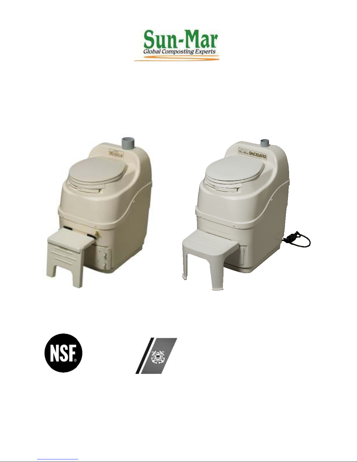
MOBILE/SPACESAVER TOILET
OWNER’S MANUAL
MOBILE SPACESAVER
Certified to NSF/ANSI Standard 41 US COAST GUARD
CERTIFIED Residential & Continuous Use
Standard 41 Issued 09/05/97 MOBILE: 1 Adults
SPACESAVER: 1 Adult
Certified for liquid containment, Weekend & Vacation Use
odors, and solid end products in MOBILE: 3 Adults
both residential and cottage use SPACESAVER: 3 Adults
RATED CAPACITY
Page 2

Models for which the manual applies:
CSES-01601W Spacesaver
CSAS-01500B Mobile
CSAS-01502B Mobile 12 Volt
Do not stand on the toilet.
Electric toilets must be installed so that electrical components in base of unit are
protected from rain, flooding, and melting snow.
Metal tools will damage the toilet.
Page 3

OWNER’S MANUAL
CONTENTS
How Composting Works
Winter Use
2 Spring Time Start Up 12
The MOBILE / SPACESAVER toilet
3 Removing Compost from
The Patented Bio-Drum 3 the Bio-Drum 13
Compost Finishing Drawer 3 Compost Troubleshooting 14
Evaporation Chamber 3 Compost Too Wet 14
Waste not Breaking Down 14
Inspection 4 Large Lumps In Drum 14
Check for Damage 4 Drum Too Full 14
Whats in the Box 4 Flies Present 14
Familiarise Yourself with the
MOBILE / SPACESAVER 4 Mechanical Troubleshooting 15-24
Attaching the Footrest 4 Urine Odor In Washroom 15
Occasional Urine Odor Outside 15
Installation 5-9 Sewage Odor when drum turns 15
MOBILE / SPACESAVER Fan Noisy 15
Rough in Dimensions 5 Fan Not Working 16
MOBILE Installation 6-7 Liquid Buildup/
‘S’ Bracket 6 Lack of Evaporation 16
‘L’ Bracket 6 Liquid Overflow 16-17
Space Required 7 Heating System Not Working 17
Vent Pipe Installation 7 Liquid In Finishing Drawer 17
Installing the Fan Filter Box 7 Drum Will Not Turn 17
Leading the Vent Through the Roof 7 Drum Door Not Opening/ Closing 17
Leading the Vent Through the Wall 7
The Deck or Roof Vent 7 Basic Instructions 18
Drain Installation 7
SPACESAVER Installation 8-9 Composting Toilet Accessories 19
Space Required 8
Vent Pipe Location 8
Leading the Vent Through the Roof 9 MOBILE / SPACESAVER
Drain Installation 9 Specifications 21
Handling Effluent 9
Start-Up and Use 10
Ongoing Toilet Maintenance 11
- 1 –
Page 4

HOW COMPOSTING WORKS
Composting is the natural process of decomposition that can be helped along by
providing the ideal conditions to help your composting toilet work at peak performance.
The ideal conditions for decomposition to occur depend on several factors: oxygen,
temperature, moisture content, and the carbon/nitrogen ratio.
Oxygen
Oxygen is very important in composting. Your compost should be aerated in order to
encourage aerobic bacteria growth. Aerobic bacteria are bacteria that grow and live in
the presence of oxygen and are very efficient in breaking down waste. To aerate the
compost and encourage the growth of these bacteria, the compost drum should be
turned three times per week (6 complete turns of the drum).
Temperature
Temperature is another important consideration when composting. Optimal composting
temperatures range between 70-100 ° F (21-38 ° C). Decomposition will slow
significantly or stop completely if the compost becomes too cold (below 55 ° F or 13 °
C). If you are in an area that experiences temperatures below 55 °F (13 ° C) additional
heat is required if the composting toilet will be used continually or frequently. If used
for intermittent cottage application (3 - 4 weekends throughout the cold season) no
additional heat is required. The unit will function as a holding tank until the temperature
warms up.
Moisture
Moisture is necessary to achieve good compost. Your compost should always be
damp, like your garden after you have watered it. This moisture allows the bacteria to
travel around in the compost so that they can speed decomposition by digesting the
waste. If the compost is too dry, the bacteria cannot survive and decomposition will
slow or cease. When adding water to the compost, you are aiming for damp compost,
not saturated. Too much liquid in the compost limits the amount of oxygen that aerobic
bacteria require to survive. If normal urination is not enough to maintain the correct
moisture level in the compost, we encourage you to add additional water to the drum.
Carbon/Nitrogen Ratio
Almost all organic material will compost. The proper bulking material and human waste
should be added to the composting toilet. In order to maintain a good balance between
carbon-rich materials, SUN-MAR Compost Sure Green and nitrogen-rich human waste
should only be added to the toilet.
- 2 –
Page 5
THE SUN-MAR MOBILE/SPACESAVER TOILET
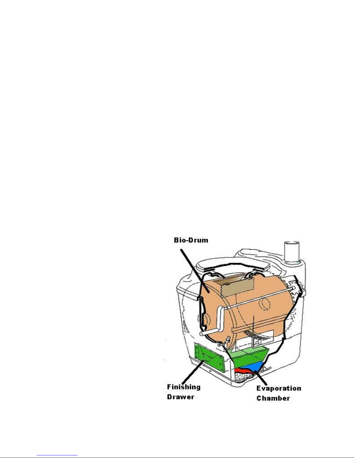
The key to the success of the MOBILE / SPACESAVER lies in its three chamber
design. Each of the three chambers; patented Bio-drum, compost finishing drawer, and
evaporation chamber, have their own independent environments for optimum
efficiency. The MOBILE / SPACESAVER features a thermostatically controlled
heater and fan assembly to help evaporate liquid and should be used where there is a
constant electrical supply.
The Patented Bio-Drum
Unique to Sun-Mar, the patented bio-drum provides the necessary mass to maintain
good compost and allows easy aeration of the compost by simply turning the drum.
Excess liquid will exit through a screen in the bottom of the drum into the evaporation
chamber. Mixing the Bio-drum is accomplished by rotating the handle in a clock-wise
direction. Compost is removed from the drum by pulling out the white drum lock button
(under the footrest) and rotating the handle in a counter clock-wise direction.
The Compost Finishing Drawer
The compost finishing drawer sits in an opening under the footrest. Compost in the
drawer is isolated from mixing with new waste while resting for 4 weeks so that it can
finish composting.
The Evaporation Chamber
The evaporation chamber is the floor
of the unit under the compost finishing
drawer. This is the area where any
excess liquid will gather for
evaporation. A safety drain exits from
the back of the composting toilet
which will drain over-flow liquid that is
not evaporated to an approved facility.
- 3 –
Page 6

Inspection
We recommend an inspection of the MOBILE/SPACESAVER toilet prior to installation and to make sure you have
received all of the parts required as listed below.
Inspecting the
unit for
Damage
What’s in the
Box
Familiarize
Yourself with
the
MOBILE/
SPACESAVER
Toilet
Attaching
and
Detaching
the
footrest
1. If there is any visible damage to the carton The contents of the carton should be inspected before signing the bill of
lading. Damaged units should be refused. Call Sun-Mar immediately.
2. If the shipper has left Report the damage immediately to the transport company and call Sun-Mar.
3. Soon after delivery, remove the MOBILE/SPACESAVER Toilet carefully
from the carton- If there is hidden damage, or for any service questions,
contact Sun-Mar to determine the best course of action.
1- Owners Manual 1 - Filter Box (MOBILE)
1- Warranty Card 1- Bowl Liner 1 - Rake
1- Hardware Kit 1- 2” Pipe Insulation (SPACESAVER)
1- Footrest 2 - 3”x 31” Vent pipe (MOBILE)
1- 1” x 8’4” Drain Hose 1- 4” Diffusor (SPACESAVER)
1- Compost Sure Green 4- 2”x31” Vent pipe (SPACESAVER)
1. Turn the drum handle clockwise to rotate the patented Bio-Drum for mixing
and aeration. (The drum rotates counter-clockwise and the drum door
closes). This is how you will rotate the drum during regular operation.
2. Pull the drum locker button, (located under the footrest) and turn the handle
counter-clockwise to simulate removal of compost. This is how you will
remove compost during regular operation.
3. (110 volt AC units) Plug the unit’s electrical cord into a standard three-prong
electrical outlet, and feel the air movement from the vent outlet at the top of
the unit to ensure the vent system is working properly.
4. Pull out the compost finishing drawer at the bottom front of the unit. After the
unit has been plugged in for ten minutes, place a hand on the floor of the
evaporating chamber (the area under the finishing drawer) to check it is
warm to the touch, and that the heater is working properly.
MOBILE: The fold up footrest attaches to the unit with hinges. To attach
the footrest, align the pin on the footrest hinge with the bracket above
the finishing drawer opening. Slide the pin into the bracket. Once the
footrest is attached it is easily folded against the unit and clipped into
place.
SPACESAVER: The footrest attaches to the unit
with the metal track above the finishing drawer
opening. To attach the footrest, incline the footrest at
a 45 degree angle to the floor as shown. Insert the
round top edge of the track on the footrest into the
round top edge of the metal track on the unit and
then lower the footrest to the floor. Note: Footrest
must be correctly attached before stepping on it.
- 4 –
Page 7
Installation
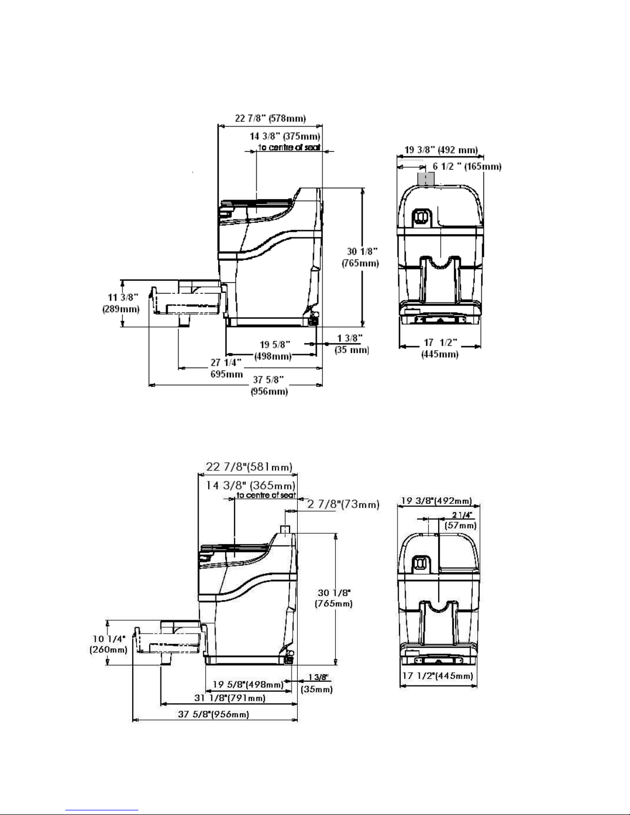
MOBILE ROUGH IN DIMENSIONS
SPACESAVER ROUGH IN DIMENSIONS
- 5 –
Page 8
MOBILE Toilet Installation
Anchoring the
Mobile
“S” Shaped
Bracket
‘L’ Shaped
Brackets
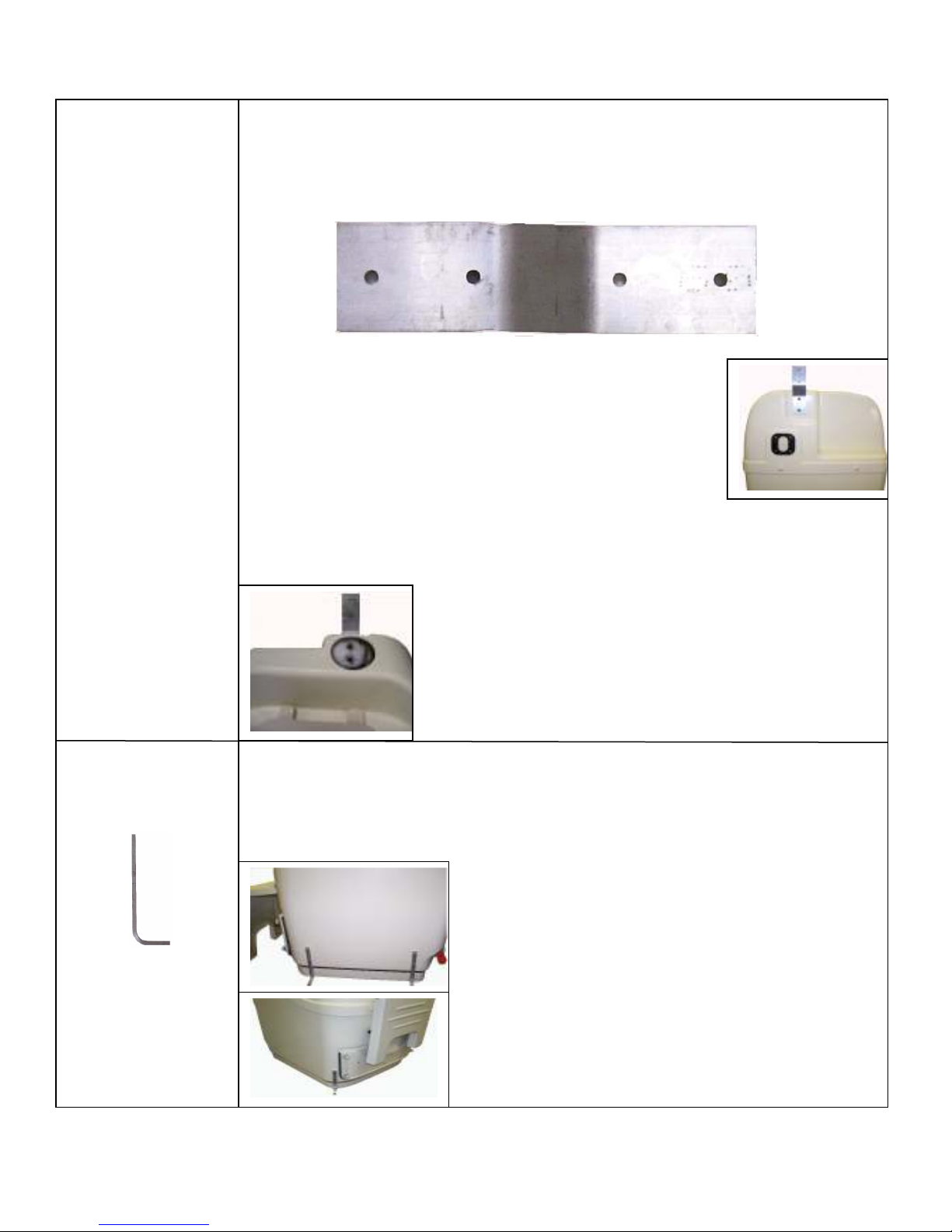
The mobile should be anchored if the unit will be installed in a vehicle that will move. There
are three anchoring brackets supplied with the unit which should be used to securely
anchor the toilet.
The ‘S’ shaped mounting bracket The ‘S’ shaped mounting bracket, (pictured below) is for attaching the top of the toilet to
the wall. (see diagram below)
1. Locate the ‘S’ Bracket (shown above), 2 nuts, 2 washers and
2 bolts.
2. Locate the two dimples (guides where to drill holes) that are just
left of centre, near the top of the unit.
3. Place the ‘S’ Bracket over the dimples to make sure the holes line
up. Using an electric drill with the drill bit(provided), drill a hole
through each of the 2 dimples on the top of the unit.
4. Place the ‘S’ bracket over the holes so that the top end of the
bracket is above the top of the unit (as shown in diagram left).
Once the bracket is in place, insert a bolt through each hole so that it is visible through the
vent hole in the top of the unit (see diagram below). Run a thin bead of silicone around the
stainless steel washer (provided) and place over the protruding bolt, on the inside of the
unit. Place a stainless steel nut over each protruding bolt and tighten.
Fastening the bracket to the wall:
1. Place the MOBILE against the wall where it will be mounted.
2. With a pencil, mark the location of the holes in the mounting
bracket.
3. Drill a small hole in each of the pencil markings to accept
anchoring screws. Use a #8 x 1” screw to anchor the
unit to the wall. Once installed, the vent pipe will hide the
bracket.
The ‘L’ bracket, (pictured left) is for attaching the toilet to the floor. (see diagram below)
1. Locate the ‘L’ Bracket in the desired location.
2. Remove the finishing drawer. Using the holes in the ‘L’ bracket as a guide, mark the
location of the two holes with a pencil. Use a drill with the drill bit (provided) to create
small holes in the side of the MOBILE tank being careful not to drill downward toward
the heating element.
3. Make sure the drilled holes line up with the holes in the
‘L’ bracket..
4. Place a small bead of silicone over the hole between
the ‘L’ bracket and the Mobile tank. Dip the bolt into
silicone and insert the bolt into the hole in the bracket
and through the corresponding hole in the Mobile tank.
5. Place a small amount of silicone into the centre of the
nut and fasten over the bolt to fasten the bracket.
Important: Ensure all bolts used for brackets are
sealed with silicone to prevent leakage.
- 6 –
Page 9

Space
Required and
other
Installation
Considerations
Vent Pipe
Location
Installing the
Fan Filter Box
Leading the
Vent
Through the
Roof
The Deck or
Roof Vent
Drain
Installation
1. Compost is removed from the finishing drawer. Ensure that there is at least 15” in front of
the MOBILE Toilet so that the drawer may be removed from the unit.
2. Install the unit in a location where the safety drain can be connected. This drain exits from
the back of the unit and must slope downward at all points.
3. Install in a location where the vent pipe can be attached as per the instructions listed
on page #9.
4. Install in a location that is not air tight.
5. Ensure that there is a three-pronged plug with a GFI (ground fault interrupter) or 12 Volt
connection installed within 5 feet of the unit.
6. Ensure the MOBILE Toilet is protected from precipitation.
7. The toilet must be installed on a level surface or sloping slightly towards the back.
1. The vent stack should be installed as near to vertical as possible. Maximum of two 45°
bends. DO NOT RUN THE VENT HORIZONTALLY AT ANY POINT.
2. Insert the 3” vent inlet coupling into the 3” hole on the top of the unit.
3. Position the fan box in the vent stack where maintenance can be carried out
conveniently.
4. If using the flexible hose, use at the top of the filter box so that moisture does not collect
in the corrugations.
5. All connectors in the vent pipe should be sealed with silicone caulking.
6. Minimize the number of sharp angles as each reduces vent efficiency. Do not use
any 90 degree elbows, since this will reduce air flow substantially.
7. Where the piping is taken through the roof, a roof flashing should be used to seal the
installation.
1. Place the fan filter box in the vent stack where it is easily accessible to
replace filter materials.
2. Remove enough of the filter materials (carbon and zeolite) so that you will
only have about 1/2” (12mm) of carbon in one filter bag and 1/2” (12mm) of
zeolite in the other filter bag (too much filter materials will stop the air-flow in
the composting unit).
3. Place the zeolite and carbon filters on top of the plastic mesh inside of the
filter box. Place the top of the filter box into the bottom of the filter box (part
with plastic mesh).
4. When attaching the filter box to the vent, use the flexible vent hose to
connect to the vent from the top of the filter box and a rigid coupling at the
bottom of the filter box.
1. Locate the area on the roof where the vent will be installed.
2. Cut a 3” diameter hole through the roof where the toilet will be located.
3. Install the 3” vent through the roof and liberally apply the self-leveling roof sealant
around the edges of the vent. Completely seal all seams and areas where water can
penetrate. Let this cure before inspecting the vent and applying more sealant as
necessary.
4. Install deck or roof vent according to the manufacturer’s instructions.
DECK VENT NOT SUPPLIED: Purchase a deck vent which fits the decor and function of
your mobile vehicle. The deck fitting should discourage downdraft and also prevent liquid
(especially sea-water) from entering the toilet. It should also encourage ventilation of the
toilet at all times.
The safety drain must be connected as it will be required in all installations.
- Remove the orange cap from one side of the overflow drain assembly.
- Place a 1” hose clamp over the end of the drain hose that will be connected to the
overflow drain assembly.
- Push the drain hose over the ribbed end of the over-flow drain and clamp with the 1” SS
hose clamp.
- Connect the 1” hose to an approved drainage facility.
- The safety drain is gravity fed. The drain hose must be below the level of the safety drain
in order to function.
- 7 –
Page 10
SPACESAVER Installation
Space
Required and
other
Installation
Considerations
Vent Pipe
Location
1.Compost will be removed from the finishing drawer. Ensure that there is at least
15” in front of the SPACESAVER Toilet so that the drawer may be removed from
the unit.
2. Install the unit in a location where the safety drain can be connected.
This drain exits from the back of the unit and must slope downward at all points.
3. Install in a location where the vent pipe can be attached as per the instructions
listed below.
4. Install in a location that is not air tight.
5. Ensure that there is a three-pronged plug with a GFI (ground fault interrupter)
installed within 5 feet of the unit.
6. Ensure the SPACESAVER Toilet is protected from precipitation.
7. Ensure that the unit is installed on a level surface or sloping slightly towards the
back.
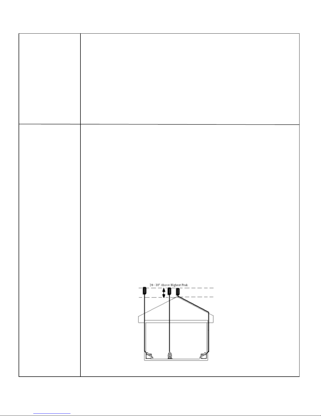
1. If running a vent through a wall, it should be done at a 45° angle to prevent con densation from accumulating in the vent pipe, causing a constriction. NO
HORIZONTAL SECTIONS OF VENT. Venting should be installed vertically.
2. All vent pipe that is exposed to the outside or in a non-heated space, should be in sulated if using the unit during cold weather.
3. INSTALL VENT SO THAT IT TERMINATES 24” - 30” ABOVE HIGHEST PEAK OF THE
ROOF.
4. If you will be installing venting on a steeply pitched roof where snow shear may occur;
Install a heavier pipe through the roof and feed the enclosed vent through the heavier
pipe. Seal between the pipes with expandable foam or other such water-tight sub stance. The heavier pipe should be able to withstand the weight of sliding snow.
5. If there is more than 36” of vent needed above the roof line to reach 24-30” above the
highest peak of the roof (diffusor included in measurement), use guy wires to secure
the vent above the roof.
6. Limit bends in the vent stack to no more than 4 that have a combined total of 180 °.
7. The vent must be installed separately from ALL other household vents. Venting cannot
be merged with other venting. Doing so will prevent the unit from operating odorlessly.
8. All connectors in the vent pipe should be sealed. Use silicone caulking to seal the
connection between the vent and the fan. PVC cement may be used for all other vent
connections.
9. The diffusor should be glued vertically on to the top of the vent pipe. This assembly
helps draw air up the vent pipe.
Possible venting configurations for the 2” electric vent pipe.
- 8 –
Page 11
Leading the
vent through the
roof
Leading the
vent through the
wall
The Diffusor
Drain
Installation
Handling
Effluent
Electrical
Considerations
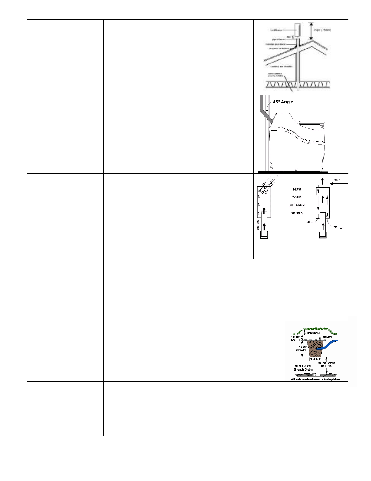
The vent stack (shown in diagram) should end
approximately 30” above the peak of the roof so that
it is less subject to downdraft. Where the pipe is
taken through the roof, a roof flashing may be
required to seal the installation. If you are in an area
where snow shear is a danger, you may wish to
install a heavier pipe around the vent pipe where it
exits from the roof. If you do choose to do this,
ensure that you seal the area between the pipes
with a waterproof substance to prevent leaks.
When it is necessary to lead the vent through a wall,
connect one 45° elbow on the vent outlet on the unit.
Using a 2” hole saw or other appropriate tool, cut a
hole through the wall board behind the unit so that
the vent pipe can be inserted into the 45° elbow. Cut
a similar hole on the other side of the wall that is
slightly higher than the inner hole so that the vent
pipe will be angled upward at 45°. If installing
through an exterior wall, waterproof sealant will be
required around the vent pipe where it emerges from
the building.
The diffusor provided with the unit is a simple device
to be installed at the top of the vent stack with the
larger pipe protruding above the smaller. To install,
simply glue the diffusor vertically on the topmost
section of vent pipe. The diffusor design encourages
updraft, and discourages wind and weather from
going down the vent stack. We do not recommend
installing anything else on the top of the vent as it
could impede the venting. Unlike wind turbines,
diffusors are less likely to freeze in winter, and are
more effective in calm weather.
The safety drain should be connected as it will be required.
- Remove the orange cap from one side of the overflow drain assembly.
- Place a 1” hose clamp over the end of the drain hose that will be connected to
The overflow drain assembly. Push the drain hose over the ribbed end of the
over-flow drain and clamp with the 1” SS hose clamp. Connect the 1” hose to an
approved drainage facility.
- Drain hose installation is required for all applications.
The following are possible options to take care of the liquid :
- Feed into a lined pit filled with gravel and sand. Such a
recycling bed also ensures a closed loop system.
- Feed into a small cesspit or “French drain”.
- Plumb into an existing septic or holding tank line.
Installation should be in accordance with applicable local
regulations.
The fan will run continuously 24 hours per day. A ground fault interrupter (GFI) circuit is
recommended for any unit installed in an environment where it will be exposed to
moisture. This may be installed directly on the wall socket or at the circuit breaker. If
you are in an area where you experience power fluctuations, you may wish to install a
surge protector.
- 9 –
Page 12
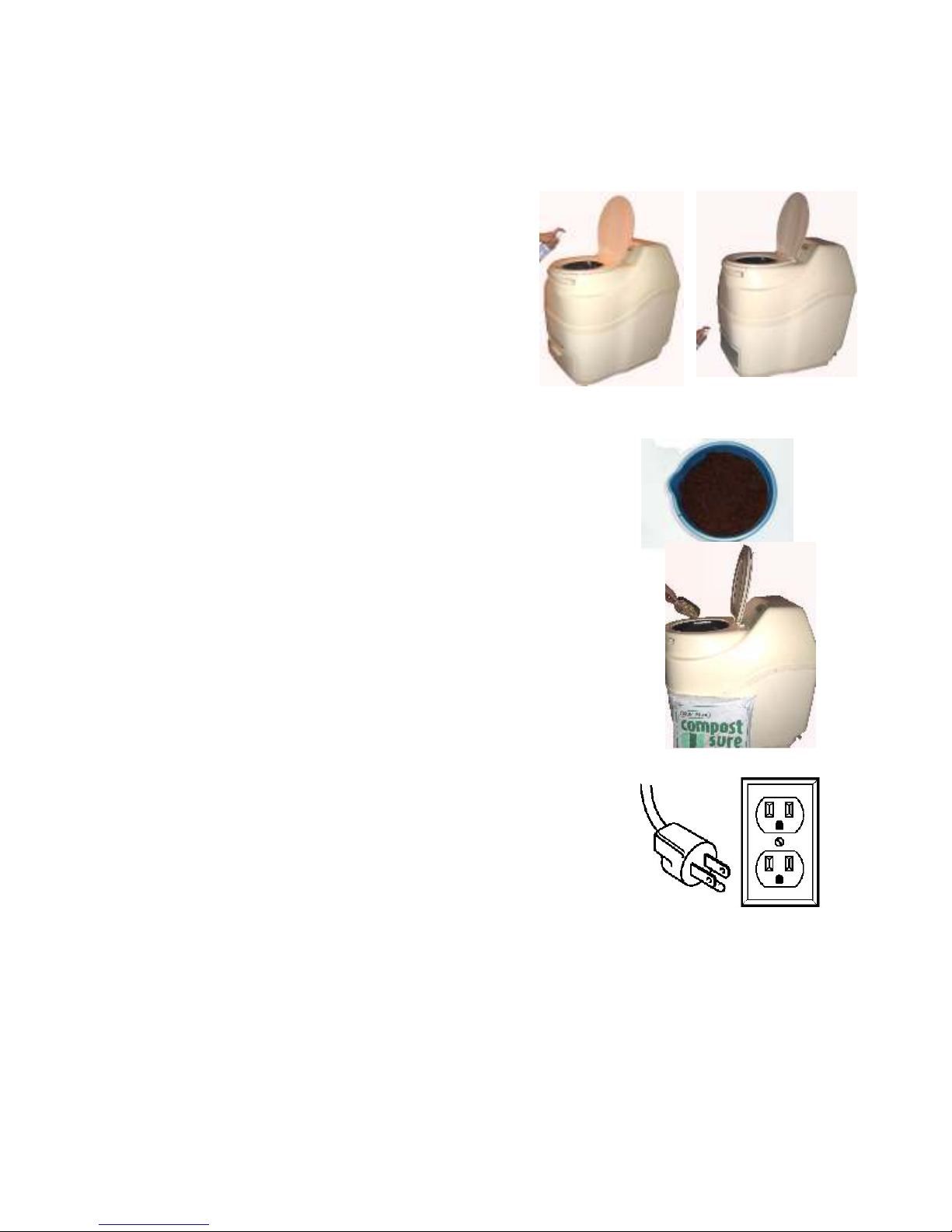
Initial Start Up and Use
These steps are only used when starting up your MOBILE/SPACESAVER toilet for the
first time or when you have emptied the drum and need to re-start the compost.
After installation is completed, do the following:
Step 1 :
and spray the whole inner floor of the unit under the
finishing drawer. Spray Compost Quick into the patented
bio-drum and the inside of the finishing drawer.
Step 2:
warm water. Add 1/2 of the Microbe Mix packet to the bucket. Allow
the Compost Sure Green to absorb the water (about an hour).
Step 3:
through the opening under the toilet seat on the MOBILE/SPACESAVER
toilet. Rotate the drum to mix. The opening in the drum must remain open
under the toilet seat. The MOBILE/SPACESAVER toilet is now ready for
use.
Step 4:
120 Volt Use: Plug it in to a three prong electrical outlet.
When you first start up the MOBILE/SPACESAVER toilet, it will take approximately 6 weeks at optimum temperatures (7090 ° F) before you will have sufficient quantities of microbes in the drum to actually achieve good compost. During this
time, the contents of the patented Bio-Drum start out as Compost Sure Green and waste. Over the first 6 weeks, you will
notice that the compost will hold moisture and will become more uniformly dark in color.
During the first 6 weeks, you may notice that some Compost Sure Green has fallen through the drum screen onto the
evaporation chamber to the left of the finishing drawer. This should be raked out and removed with the rake tool provided
with the unit.
Spray Compost Quick: Remove the finishing drawer
Pour 1/3 bag of Compost Sure Green into a bucket and add 2 quarts of
Scoop the Compost Sure Green mixture into the patented Bio-Drum
For electric units only. The fan will run continuously 24 hours per day.
NOTE: Regular toilet paper may be used. Toilet paper is a good source of carbon for your compost so it may be
added to the Bio-Drum™
- 10 –
Page 13

Ongoing Toilet Maintenance
Once your MOBILE/SPACESAVER toilet is installed and you have gone through the initial start-up
procedure, follow the steps outlined below to keep your composting toilet working optimally.
Add one cup of
Compost Sure Green
per person per day of
use
Spray Compost Quick
on the surface of the
compost
Turn the handle
clockwise every
second day to mix the
compost
Make sure that the
opening in the drum
is centered under the
toilet seat.
Every two weeks
Every three months
Twice per year
Periodic maintenance
1) Do NOT add or clean the toilet bowl liner with chemicals. Chemicals will kill the bacteria. INSTEAD, clean the bowl
liner with Compost Quick.
2) Do NOT add plastic, glass, metal, cleaning fluids, cigarettes. Add only waste and bulking material.
3) Kitchen or garden waste, are NOT recommended.
4) Do NOT add baby wipes, diapers or feminine paper as they will not compost.
Even if you only use the toilet for urination then at least one cup of
Compost Sure Green should be added per person per day of use.
Add the Compost Sure Green through the hole under the toilet seat
of the MOBILE/SPACESAVER toilet.
Every second day before turning the handle, spray 3-4 sprays of
Compost Quick on the surface of the compost. Compost Quick is an
enzyme that will speed up the composting process.
Turn the handle in a clockwise direction to mix and aerate the
compost. When mixing, ensure that the drum rotates 6 complete
revolutions (36 turns of the handle).
The hole in the drum must be open under the toilet seat, ready to
receive waste.
Add one scoop of Microbe Mix to the patented bio-drum to ‘recharge’
the pile. This will help to ensure your microbe colony stays constant
and healthy.
Rake the evaporation chamber: Remove the finishing drawer. Rake
any solid debris from the floor of the unit under the drawer
(evaporation chamber), paying extra attention to the two back
corners of the unit as this is where debris may accumulate. Remove
the solid debris.
Clean the drum screen. Spray the drum screen with Compost Quick
and let sit for 15 minutes (this will help to loosen the debris if the
screen is not too encrusted). Scrub the screen vigorously with the
wire brush. If brushing the screen does not clear it and liquid is still
not draining through the screen, you may have to resort to having to
use a screwdriver or nail to puncture each hole in the drum screen.
Remove compost from the drum. When the drum is half full (even
with the middle of the drum hub at the front of the drum) it is time to
remove compost. To remove compost from the drum:
See page 13 of your Owner’s Manual
CAUTION
- 11 -
Page 14

Seasonal Use and Springtime Start Up
Empty Compost from Last Season
Before your first use of the unit, extract compost from the drum by releasing the drum locker (located
above the drawer opening), then rotate the handle counter-clockwise giving the drum one complete
revolution only. Compost from the drum will drop into the finishing drawer. Empty the drawer and
repeat this procedure until most of the compost is removed, leave 3-4” of compost. This will be your
“starter base” for the coming season.
Rake
Remove the finishing drawer completely and use the rake tool to rake any loose material from the
floor of the unit. Pay careful attention to the back two corners of the unit (near the safety drain), to
ensure that your drains do not get clogged.
Add Water & Microbe Mix
Add some warm water to the remaining compost, enough to ensure that it is quite moist. Also, add
some Sun-Mar Microbe Mix (two of scoops) to give the compost pile a “kick-start” and rotate the drum
several times to mix. If your composting toilet is electric, plug it in and use for another season.
Winter Use
No Winter Use
Just add water, lots of water. Soak the compost in the drum to prevent it from drying out before
Spring. Make sure to unplug the unit if electric.
Occasional Winter Use
If the unit will be used for 3-4 weekends throughout the winter season then it is considered occasional
use. All of the same considerations should be taken with these units to winterize them. When the
temperature dips below 55 ° F (13 ° C), composting activity will decrease dramatically. These units do
not need to be kept warm and will act only as a holding tank during the winter months until they warm
up enough in the spring to begin composting again. During the winter, the compost will freeze into a
solid mass so the drum should not be turned as it may damage the composting toilet. With this in
mind, it is a good idea to remove enough compost before it gets too cold to make room in the drum
for winter use.
Heavy or Residential Winter Use
These units should be kept in a heated area and all winterization tips should be followed, including
the following:
1) Vent Pipe - all vent pipe should be insulated if they are exposed to the outside or in an unheated
area. If you are in an area that experiences extreme winter conditions, we recommend that heat
tape should be applied to the exposed vent pipe to prevent ice blockages.
2) Safety Drain - all models; we recommend that the safety drain should be installed and insulated
above the frost line. There will be less evaporation in the winter so this will help with any excess
liquid. If possible, heat tape can be applied to the safety drain to prevent ice blockage.
3) Keep it warm; If the composting toilet is used frequently in the winter then the composting part of
the unit should be kept in a warm place. Below 55 ° F (13 ° C), composting actions slows
dramatically so if it is in a place that falls below this temperature, a source of heat should be
provided for the unit so that it can keep up with constant use.
- 12 –
Page 15
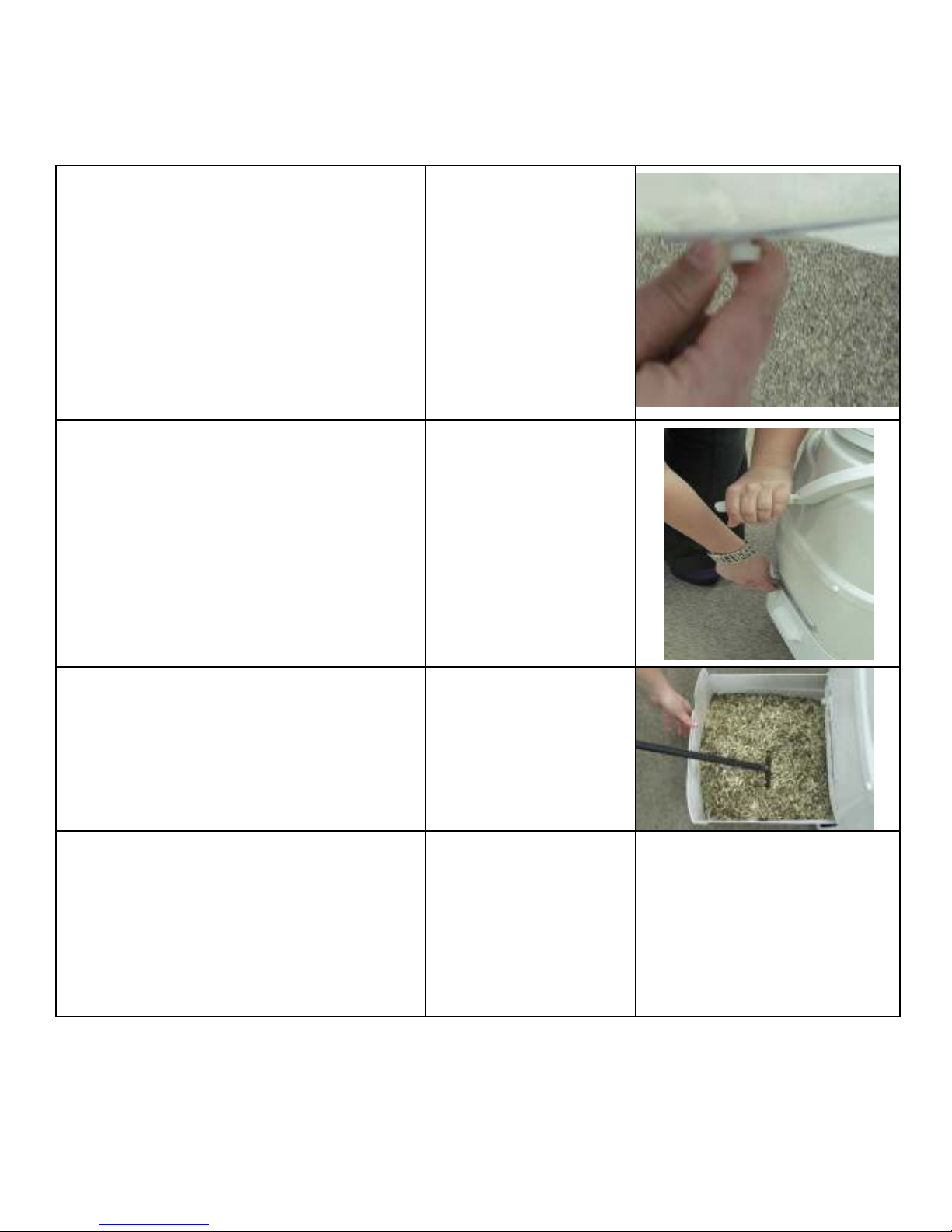
Removing Compost from the patented Bio-Drum
Pull the
The level of compost in the patented Bio-drum should never be more than half full. As a guide, the
compost in the drum should be at least 4 inches from the bottom of the drum door. Compost must be
removed from the drum by following the steps outlined in this section.
drum lock
Button
Turn the
handle
counterclockwise
Level the
compost
in the
drawer
Allow the
compost
to rest
Compost may be removed at any time that you may need more space in the drum and will need to be
removed more frequently for heavily used units or where the MOBILE/SPACESAVER toilet is the
primary residential toilet.
Remove the footrest from
the front of the toilet. Pull
the drum lock button out
and hold it out while
turning the handle.
While holding the drum
lock button out, turn the
handle counter-clockwise
for three revolutions of
the handle. Release the
drum lock button and
continue to turn the
handle counter-clockwise
until the opening in the
drum is under the seat.
Open the drawer and use
rake to level the
Compost.
Compost should now be
allowed to rest in the
drawer for 3 - 4 weeks to
finish the composting
process.
The drum lock button
is attached to a bar
that sits in a molded
depression in the
drum. When the
button is pulled, the
bar is pulled out of the
depression which
allows the drum to
turn in the opposite
direction.
The drum door will
stay open allowing
compost to fall into
the finishing drawer.
Fresh and composted
material will be
deposited into the
drawer.
Leveling the compost
will prevent compost
from soiling the
patented bio-drum.
This compost will be
isolated from any new
waste and should
be left in the drawer
for a minimum of 4
weeks or longer to
finish composting.
- 13 -
Page 16

Compost Troubleshooting
3.
Use “Compost Sure Green”.
Symptom Cause Remedial Action Prevention
Compost
Too Wet
Waste not
Breaking
Down at all
(the drum
will fill up
quickly)
Large
Lumps
in
Compost
Drum Too
Full
Flies
Present
Compost porosity
is poor.
Drum screen
clogged
Insufficient
moisture in
compost
Insufficient
Microbes
Room
Temperature
Under 55 ° F/13°C
Compost Too Dry
Compost not
emptied into
finishing drawer
in a timely fashion
Kitchen/Garden
Waste added
-compost too
dry
-compost
anaerobic
-foreign material
added
Change bulking material to Compost Sure
Green.
Spray the drum screen with Compost
Quick. Scrub the drum screen with wire
brush.
A moisture content of 40-60% is ideal for
aerobic microbes to thrive.
Add Sun-Mar Microbe Mix.
Install heat source to increase temperature.
Temperature should be kept above 55 °
F
/13°C constantly to ensure the composting
action does not stop completely.
Add 1/2 to 1 gallon of warm water to
compost in order to bring it up to
appropriate moisture level.
Remove lumps or break them apart.
Remove compost until drum is only half full
or less. Rotate compost thoroughly to
aerate, and add compost accelerant
(Compost Quick and Microbe Mix) if
available.
We do not recommend adding kitchen or
garden scraps.
1.To eliminate flies, you can use any
pesticide that is used on your garden.
Pesticides used for garden use are not
anti-bacterial so are safe to use on your
compost.
2. The alternative to using pesticides is to
completely clean the toilet out, wash the
inside with soap and water
IMPORTANT:
Application of a pesticide in a SUN-MAR
toilet is not a health concern because all
SUN-MAR units are vented.
If using pesticides, avoid spilling on the
outer shell of the composter
- 14 –
- 14 –
Use Sun-Mar Compost Sure
Green
Add water to patented biodrum
Be sure to add microbe packet
at start up.
Install unit in warm area. The
warmer the area, the better
your compost will be!
Use proper bulking material
and add warm water if
necessary.
When drum is 1/2 full, remove
some compost to the finishing
drawer. Do NOT let drum get
above 1/2 full. This will lead to
lack of aeration, and anaerobic
compost.
Do Not add kitchen or garden
waste.
1. Keep compost moist. In
order to determine a good
level of moisture, shine a
flashlight into the drum. The
compost should have a slight
gloss or shine. If it does not,
add warm water to it until it
reaches this consistency.
Fungus gnats tend to be
attracted to a dry compost,
due to the fungus which
begins to form on the surface
when it dries out. A good,
moist compost will not be
attractive to flies.
2. Do not add topsoil from the
ground, composted matter, or
kitchen scraps to the toilet.
Flies may be present in, or
attracted to these items.
Page 17
Symptom
Cause
Remedial Action
Prevention
Urine
Odour in
Washroom
Occasional
Urine Odor
Outside
Strong
Sewage
Odor
Fan Noisy
MECHANICAL TROUBLE SHOOTING
Horizontal runs or
downward slopes
on vent pipe
Fan has failed
Downdraft
Competing
appliances
Incorrect installation
of
filter box (MOBILE)
Too much carbon
or zeolite in filter
box (MOBILE)
1. Vent stack not
installed above
peak of roof.
2. If vent stack is
installed above
roof line, natural
obstructions, such
as tall trees, being
located in a valley
or close to a hill
may be causing
downdraft.
Compost is
anaerobic
Fan damaged in
shipping or
bearings are
beginning to wear.
Re-install the vent so there are no horizontal or low points where condensation
can collect.
Have your serial number ready and call
SUN-MAR for a replacement. Instructions
are included with the replacement fan.
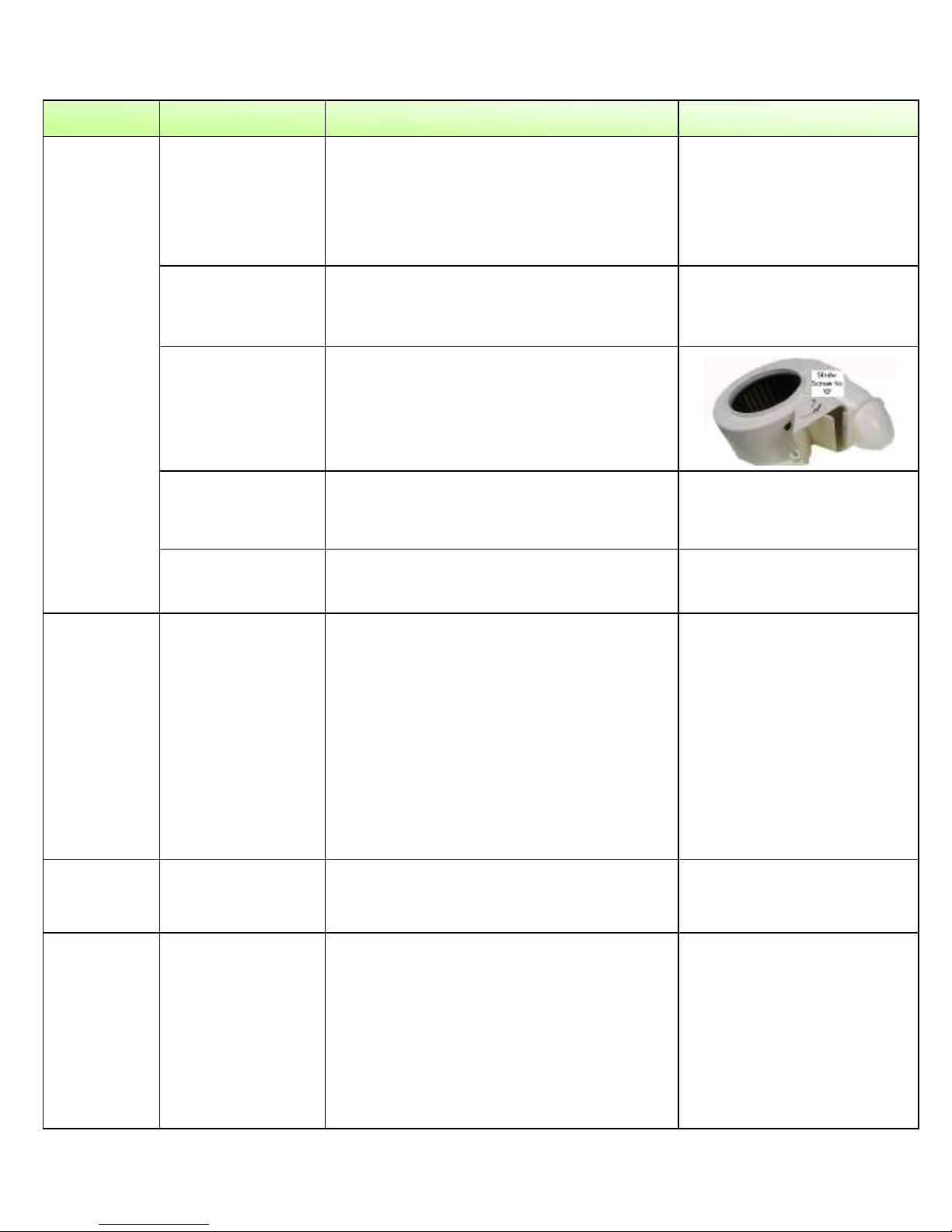
If you believe that there may be a downdraft outside of the building, it may be a
good idea to remove your fan assembly
prior to installation and set the fan gate to
‘0’ to prevent urine odor in the bathroom.
(SPACESAVER)
Ensure that filter box is installed with fan in
the top portion of the box.
Remove some filter material to allow
unobstructed venting of unit.
1. Check that the vent is installed above
the peak of the roof. If not, extend the
vent. Guide wires may be necessary.
2. Add lime to the evaporation chamber –
as much as you think necessary. You
will have to rake more often if you do
this.
3. (SPACESAVER) SUN-MAR has a filter
box available which will filter the
ammonia out of the vented air in a
downdraft situation. Call SUN-MAR for
details.
Begin following: “Compost troubleshooting”
suggestions.
1. If it is rattling, it may need to be cleaned
or the bearings are worn and the fan
needs to be replaced.
2. A hum is the normal sound the fan will
make. If you are in a very quiet setting it
will be more noticeable.
- 15 –
Install wall brackets on vent
pipe to prevent settling. DO
NOT install horizontal runs
as liquid will collect and
block ventilation, causing
odor.
The fan is a constantly
moving part and has a finite
service life.
Large amounts of carbon or
zeolite will prevent air flow.
Initially, install the vent
above the peak of the roof.
If symptoms occur, add lime
or a filter box.
(SPACESAVER)
Follow “Ongoing Maintenance” and use proper
bulking material.
Clean the fan with a small
brush and/or compressed
air nozzle once a year.
This will prevent wear and
lengthen the life of your fan.
Page 18

Symptom Cause Remedial Action Prevention
Fan Not
Working
Liquid
Build up/
Lack of
Evaporation
Liquid
Overflow
Debris in fan or
mechanical failure.
Increased usage.
Climactic
conditions
Mineral salts may
have accumulated
in the evaporation
chamber over time,
reducing
evaporation rates.
Drains Blocked
Overflow drain not
hooked up
Unit tipped forward
Remove the fan assembly from the unit and
vacuum any dust out of the fan blades.
Check the power source. If this does not
remedy the problem, have your serial
number ready and call SUN-MAR
The amount of liquid varies substantially
between installations. The overflow drain
must be installed.
Evaporation rates vary substantially with
climatic conditions. Expect faster
evaporation rates during warm dry weather.
To remove these, fill the evaporation
chamber with very hot water and 1/3 bottle
of “Compost Quick” enzyme liquid. Leave
overnight.
1. Rake peat moss away from the safety
drains. This is the “build up” area. If
drains are still clogged, proceed to step
3.
2. Check drain line for kinks, blockages or
upward bends. Remove and flush if
blockages present, un-kink if bent and
ensure that the drain pipe is sloping
downward. If your drain pipe is in order,
proceed to step 3.
3. Use a wire to poke blockage out of the
Drain assembly. A brown spot will be
visible through the opaque assembly.
Connect overflow safety drain
Check and ensure that the unit is level.
- 16 –
The fan is a continuously
moving part which will
eventually have to be
changed. Do Not turn on
and off daily.
Install the overflow drain.
Rake evaporating chamber
at spring start ups for
cottage use, and once
every other month for
residential use.
1. A clogged drain is not
very likely to happen if
evaporating chamber is
raked every 3-4 months.
2. Use premium 1”ID hose
for the drain line. A good
hose will be less likely to
kink. Use elbows or
fittings around bends to
prevent kinks.
3. Use Compost Sure
Green as a bulking
material.
Evaporation will slow during
damp weather, make sure
drain hose is installed.
Page 19

Symptom Cause Remedial Action Prevention
Heating
System Not
Working
Liquid in
Finishing
Drawer
Drum Will
Not
Turn
Drum Door
Not
Opening/
Closing
Properly
Test to determine
whether failure has
occurred
Thermostat Failure
Heating Element
Failure
Drum Screen
Clogged
Set screw securing
handle to shaft has
broken
Steel roll-pin
securing gear
wheel to shaft has
broken
Drum too full
Hinges Stuck
Pull finishing drawer out and put your hand
in the evaporation chamber (NOT in the
liquid). If there is no warmth rising from the
floor of the unit, your heating system is not
working. It is most commonly the
thermostat that has failed. If you notice a
Lack of evaporation, but there is still
warmth in the heating chamber, see “Liquid
Build up” for solutions.
Have your serial number ready and call
SUN-MAR for a replacement. (Detailed
instructions are included with the
replacement part)
If the insulation behind the electric box is
moist or discolored, or heating does not
work after the new thermostat has been
connected, then the heating element has
failed.
Rotate the drum 180 ° so that the drum
screen is on top - you will just be able to
see the edge of it if you take out the bowl
liner.
Drill out set screw and replace, or have
your serial number ready and call SUNMAR for a handle replacement kit
(instructions included).
Have your serial number ready and call
SUN-MAR for a replacement small gear kit.
Spray hinges with Compost Quick. Scrub
hinges with toothbrush or other soft nylon
bristled brush.
- 18 -
jkgkjhgjk
- 17 -
A ground fault interrupter
circuit is recommended to
protect your MOBILE/
SPACESAVER Toilet from
power surges that could
cause your heating system
to malfunction.
Your thermostat and fan are
the two constantly moving
parts on the unit, and so are
the most likely to fail.
If you ever remove the unit
from the bathroom for
cleaning, DO NOT use a
water hose around the base
of the unit.
Scrub drum screen with a
wire brush.
Drum should never be more
than ½ full.
Page 20

MOBILE/SPACESAVER Toilet Basic Operating Instructions
These instructions are not to replace the owner’s manual, but are intended as simple instructions for
daily use.
1) USING THE TOILET If it’s yellow, let it mellow. Good advice! If you simply urinate in the toilet,
deposit your toilet paper in the toilet, close the lid and walk away…your job is done! If the toilet is
being used predominantly for urination, be sure to add at least one cup of bulking mixture per
average amount of users per day. If you make a more substantial contribution, deposit your toilet
paper and one cup of Compost Sure into the drum of the toilet. Close the lid and walk away!
2) Every other day, turn the handle to mix and aerate the compost.
Pull the handle from under the seat and turn in a clock-wise direction only. Open the lid of the
toilet
seat. Watch as the drum turns. The opening in the drum should come to the top of the drum 6
times. Once you have completed turning the drum, make sure the opening for the drum is centered
under the toilet seat. Fold the handle back under the seat, close the toilet seat lid and you are
done. Only turn the drum every other day!
Bulking Material
When you run out of our Compost Sure bulking material, more Compost Sure through your Sun-Mar
dealer, on line at www.sun-mar.com. Do not use 100% peat moss as this will clog your drum screen
and drains.
Periodic Maintenance
Rake out evaporation chamber with rake provided (the area below the finishing drawer). Clean the
drum screen. Remove the bowl liner and lift the toilet seat. Turn the handle 3 revolutions to bring the
drum screen to the top of the drum. Access can be gained by reaching through the hole under the
toilet seat. Spray the drum screen with Compost Quick and let sit for 15 minutes (this will help to
loosen the debris if the screen is not too encrusted).
Scrub the screen vigorously with the wire brush. If brushing the screen does not clear it and liquid is
still not draining through the screen, use a screwdriver or nail to puncture each hole in the drum
screen.
Attention: the MOBILE/SPACESAVER Toilet electric model must remain plugged in to an
electrical outlet continuously to function odorlessly. If you will be away from the residence
where the composting toilet is installed for longer than three days, the power may be
disconnected while the composting toilet lays dormant.
- 18 –
Page 21
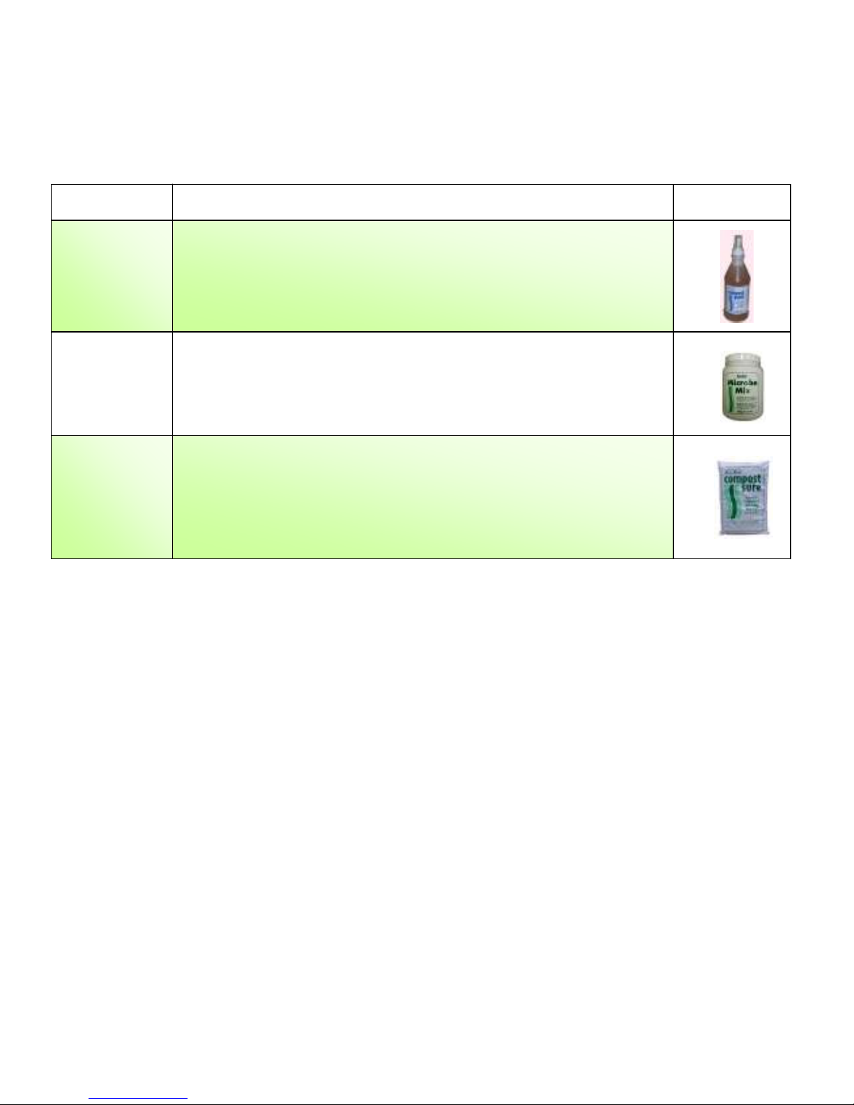
ACCESSORY ITEMS FOR THE SELF CONTAINED TOILET
SUN-MAR has developed a number of composting accessory items over the years in response to
frequent requests from users. These items may serve to improve composting speeds under some
circumstances.
Name Description Container
Cleans and accelerates the composting action of your Sun-Mar
“Compost
Quick”
composting toilet. Compost Quick is a specially selected
natural enzyme solution that also assists in the decomposition
of waste. 100% natural and non-toxic. 500ml(16oz) Bottle
100% natural product combining a blend of microbes and
“Microbe
Mix”
enzymes designed to start and accelerate composting in all
Sun-Mar toilets. 500g (16oz) Jar
The ideal bulking agent for your Sun-Mar waterless toilet.
“Compost
Sure
Green”
Compost Sure Green is specially formulated to keep compost
enriched with organic carbon, moist and maintain porosity
ensuring maximum aeration. 30 Litre/8 Gallon Bag
Note: Use “Compost Sure Green” for optimum results.
- 19 –
Page 22

Page 23
- 20 –
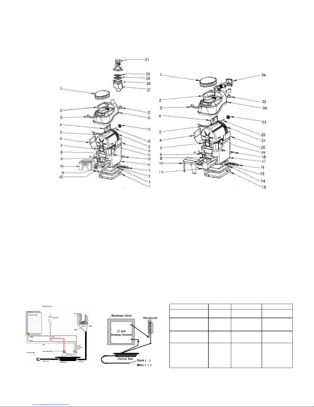
MOBILE / SPACESAVER SPECIFICATIONS
EXPLOSION DIAGRAM & PART NUMBERS
MOBILE SPACESAVER
1 Toilet Seat 11 Drawer 23 Nylon Drive Gear
2 Bowl Liner 12 MOBILE Face Plate 24 Top
3 Front Cover 13 SPACESAVER Heating Tray 25 Shaft Holder
4 Drum Door 14 Heating Element C9806 26 PACESAVER Fan
5 Handle Kit 15 Thermostat 27 Filter Box (MOBILE)
6 Humus Deflector Left 16 Electric Box 28 12 Volt 5.4 Watt Fan(MOBILE)
7 Front Bearing Plate 17 Tank 29 Zeolite Filter (MOBILE)
8 Snap Apart Hinge (MOBILE) 18 1” (25mm) Drain Assembly 30 Carbon Filter (MOBILE)
8 Footrest Channel 19 Drum Screen
9 Drum Locker 20 Humus Deflector Right
10 Folding Footrest (MOBILE) 21 Patented Bio-Drum
10 Footrest (SPACESAVER) 22 Shaft
Electrical Specs MOBILE MOBILE 12V SpaceSaver
Maximum Amps 2.0 8.0 1.2
Fan Watts
(Required) 5 .4 req . 5.4 req. 35req.
Heater Watts 160 90 160
(When on)
Average Power
Use In Watts 85 50 110
(Heater on
½ time)
MOBILE/SPACESAVER MOBILE 12 VOLT
Page 24

- 21 –
PO-MANU0-0620BX
WARRANTY
SUN-MAR Corp. warrants the original purchaser that this toilet is free from defects in
material and workmanship under normal house or cottage use. SUN-MAR Corp. will
furnish new parts for any part that fails within three years and five years on the
fiberglass tank, provided that our inspection shows that such failure is due to defective
material or workmanship. Any part supplied by us to replace another part is warranted
for the balance of the original warranty period.
This warranty does not cover:
1. Damage resulting from neglect, abuse, accident or alteration; or damage caused by
fire, flood, acts of God or any other casualty.
2. Parts and accessories not sold or manufactured by SUN-MAR Corp. or any damage
resulting from the use of such items.
3. Damage or failure resulting from failure of the purchaser to follow normal operating
procedure outlined in the Owner’s Manual or in any other printed instructions.
4. Labor and service charges incurred in the removal and replacement of any parts
found defective under the terms of this warranty.
5. All returns to the factory must be made freight prepaid. All shipments from the
factory are made F.O.B. the factory.
This warranty is in lieu of all other warranties expressed or implied, and no person is
authorized to enlarge our warranty responsibility, which is limited to the terms of this
certificate. The Company reserves the right to change, improve or modify its products
without obligation to install these improvements on equipment previously
manufactured.
Product Info: (905) 332-1314 Fax: (905) 332-1315 Tech. Service: (888) 341-0782 Ext 218
Tonawanda, N.Y. Burlington, ON
14150-0888 U.S.A. L7L 5L1 CANADA
E-mail: [email protected] http://www.sun-mar.com
600 Main St. 5370 South Service Rd.
NOV 2014
Rev.D7
 Loading...