

Sun-Mar CENTREX 3000NE, CENTREX 3000 series, CENTREX 3000 AC/DC Owner's Manual
Serial # ________________
“CENTREX 3000 FAMILY”
OWNER’S MANUAL
RATED CAPACITY
Weekend & Vacation Use
(Cottage Use)
8 Adults or families of 10 or
9 Adults or families of 11
Residential & Continuous Use
5 Adults or a family of 7 or
6 Adults or families of 8
Standard 41
Certified for liquid
containment, odors, and
solid end products in cottage use
Certified to NSF/ANSI Standard 41
CENTREX 3000
CENTREX 3000 AC/DC
CENTREX 3000 NE

- 1 -- 28 -
OWNER’S MANUAL
CONTENTS
Chapter 4
Chapter 5
I
ntroduction
Chapter 1
Chapter 2
Chapter 3
How your composting
toilet Works
How Composting Works
The Composting Chamber
Compost Finishing Drawer
Evaporation Chamber
Winter Use
CENTREX 3000 Family Part
Numbers
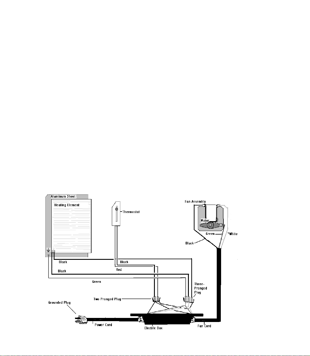
Wiring Diagram
CENTREX 3000 Family Explosion
Drawing
Inspection
Check for Damage
Check for Parts and Functionality
Placement of unit
Installation
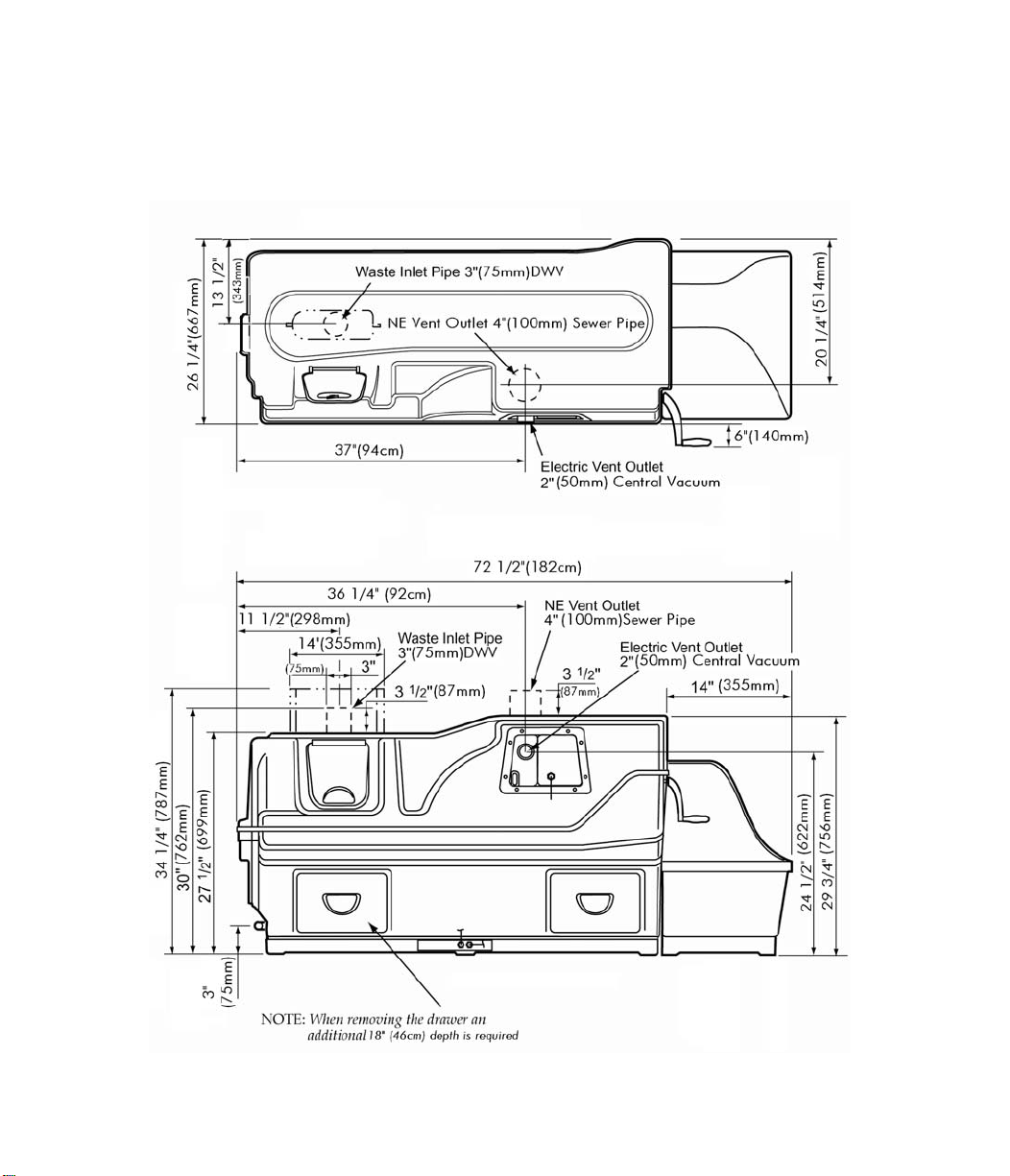
CENTREX 3000 Rough in
Dimensions
Included in your kit
Installing the 1 (500ml) Pint
Low-Flush Toilet
Installation Considerations for
the Waste Pipe
The 3” (75mm) Waste Inlet
The Compost Collection Bin
Drain Installation
Handling Effluent
Vent Pipe Location
Adjusting the Fan Gate
Vent Pipe Installation
Leading the Vent through the roof
The Diffusor
Electrical Considerations
12 Volt Fan Installation
Start Up and Use
Initial System Start Up
Annual Start Up
Periodic Check Up
Ongoing Maintenance
2-5
2
2
2
3
3
3
4
4
5
6
6
6
6
7-12
7
8
8
9
9
9
9
10
10
10
10
11
11
11
12
13-15
13
14
14
15
Compost
Troubleshooting
Requirements of an Aerobic
Compost
Compost Too Wet
Compost Too Dry
Waste not Breaking Down
Lumps
Drum Too Full
Flies
Mechanical
Troubleshooting
Urine Odor In Washroom
Occasional Urine Odor Outside
Sewage Odor when drum turns
Fan Noisy
Fan Not Working
Liquid Buildup/
Lack of Evaporation
Overflowing Liquid
Heating System Not Working
Liquid In Finishing Drawer
Drum Will Not Stay Vertical
Drum Will Not Turn
Drum Door Not Opening/
Closing
Waste Not Exiting Waste Pipe
Composting
Accessories
Basic Maintenance
Warranty Information
Electrical Specifications
Getting Ready for
Winter
16-19
16
17
17
17
18
18
19
20-24
20
21
21
21
22
22
22
23
23
23
24
24
24
25
26
27
28
29

Introduction
HOW YOUR COMPOSTING TOILET WORKS
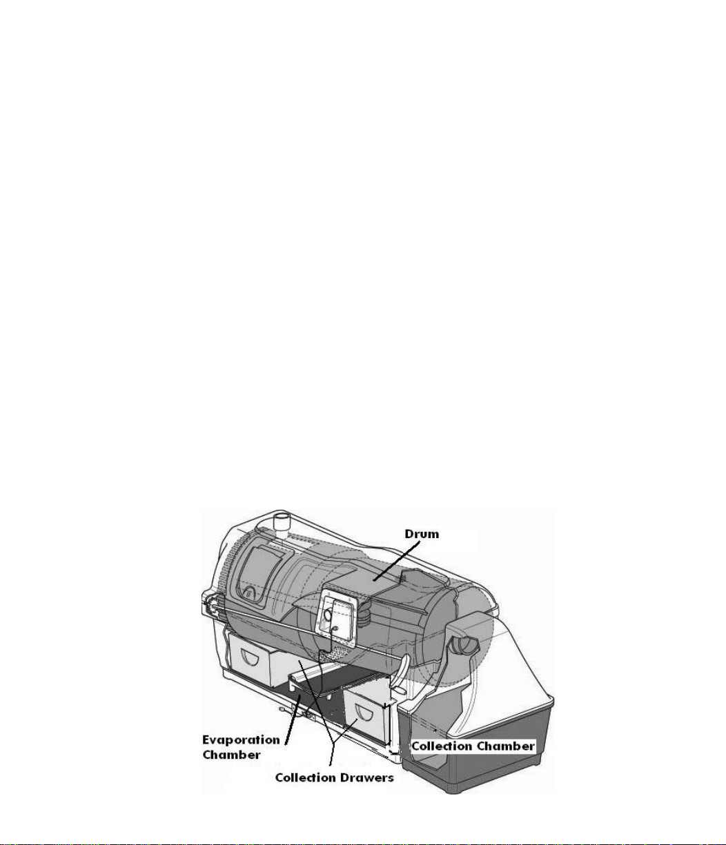
The key to the success of the “CENTREX 3000 ” lies in it’s three chamber design. Each of the three chambers; composting, compost finishing, and evaporation have their own independent environments for optimum efficiency.
Composting is a natural recycling process where human
waste and toilet paper are broken down by microbes
into minerals and converted back to earth. Heat, oxygen, organic material and moisture are needed to transform this waste into good fertilizing soil, perfect for your
flower beds.
Oxygen is provided by the ventilation system, and by
tumbling of the composting drum. Additional organic
material is introduced by adding“Compost Sure Blue”
(or 100% shavings). The waste entering the toilet is
approximately 90% water content. Any excess liquid
which is not absorbed will collect on the floor of the unit
(evaporation chamber) where it may be evaporated into
water vapor and carried back to the atmosphere
through the venting system. The remaining waste material is transformed into an inoffensive earth-like substance.
The Composting Chamber
The composting chamber is in the form of a Bio-drum
which holds the natural compost heat, provides the necessary mass to maintain a good compost, and is rotated by turning the handle to achieve perfect mixing and
aeration.
During mixing, the input door at the top left will remain
closed. When the drum returns to the top dead centre
position ready to receive more waste, the input door will
remain open.
A drum stopper behind the doghouse on the right side
of the unit automatically holds the Bio-drum in a top
dead center position so that it is always positioned to
receive new material.
Compost is extracted from the drum by continuously
feeding into the collection bin (doghouse) whenever the
drum is rotated.
To ensure that the compost remains moist, but does not
get too wet (between 40 and 60% moisture content is
ideal), any excess liquid which the compost cannot
absorb drains through the screen in the bottom of the
drum directly onto an evaporating tray beneath the
screen, and from there, overflows into the larger evaporating chamber. The evaporating tray can be removed
periodically to remove peat moss debris that has accumulated.
Compost Collection Drawers
and Chamber
The compost collection drawer is at the extreme right
and left of the unit below the composting drum, and just
above the evaporating chamber. The right drawer is
used only if you wish to completely empty the drum.
The collection drawer on the left is merely to provide
access to the evaporation chamber. Compost from the
drum will automatically feed into a collection chamber at
the far right end of the unit.
Evaporating Chamber
The third chamber is the floor of the Sun-Mar “CENTREX
3000” which forms the evaporation chamber from
where excess liquids are evaporated. You will always
see liquid in this area.
- 2 -
- 3 -
Winter Use
Because "Sun-Mar" units are made largely of fiberglass
and high grade stainless steel, freezing temperatures
will not damage the composting unit. Composting action
decreases as the temperature drops, so for continuous
use, the composting unit should be kept constantly at or
above 55-60 degrees F (13-15 C). All exposed vent
stack should be insulated (right up to 2" or 5cm below
the diffusor) to minimize the condensation in the pipe
and avoid ice blockages. Drain pipe should be insulated or, in extreme temperatures, heat tape used to prevent ice blockages.
In extreme temperatures, an additional source of heat
will also be required.
If the compost is frozen in the drum, the unit may be
used periodically as a "holding tank", until the compost
warms up and the microbes emerge from dormancy.
Space should be made in the drum prior to freezing to
accommodate winter use. The drum should NOT be
rotated when the compost is frozen.
Make sure that the composting unit is protected from
snow and ice accumulation to ensure that moisture
doesn't get into the heater base. It is a good idea to
put a tarp over the composting unit to protect it from
snow.
In Electric or AC/DC units, air is pulled through intake
holes at the rear of the unit; over the evaporating
chamber, and up the 2” (50mm) vent stack which exits
from the front of the composting unit when AC power is
being used.
When using the NE or AC/DC units and AC power is
unavailable, natural draught caused by the chimney
effect combined with a 12 volt fan draws air into the unit
and up the 4” (100mm)vent stack.
In Electric or AC/DC units using the AC mode, the evaporation process is further assisted by a thermostatically controlled heating element in a separate sealed compartment under the evaporating chamber. This heater
is largely on when there is liquid in the evaporating
chamber, and largely off when the chamber is dry. The
heating system maintains warmth in the evaporating
chamber, and the indirect warmth assists the composting process, without the compost drying out. An safety
drain exits from the left side of the composter which
drains off any excess liquid to a cess pool, recycling
bed, old septic bed or other approved facility.
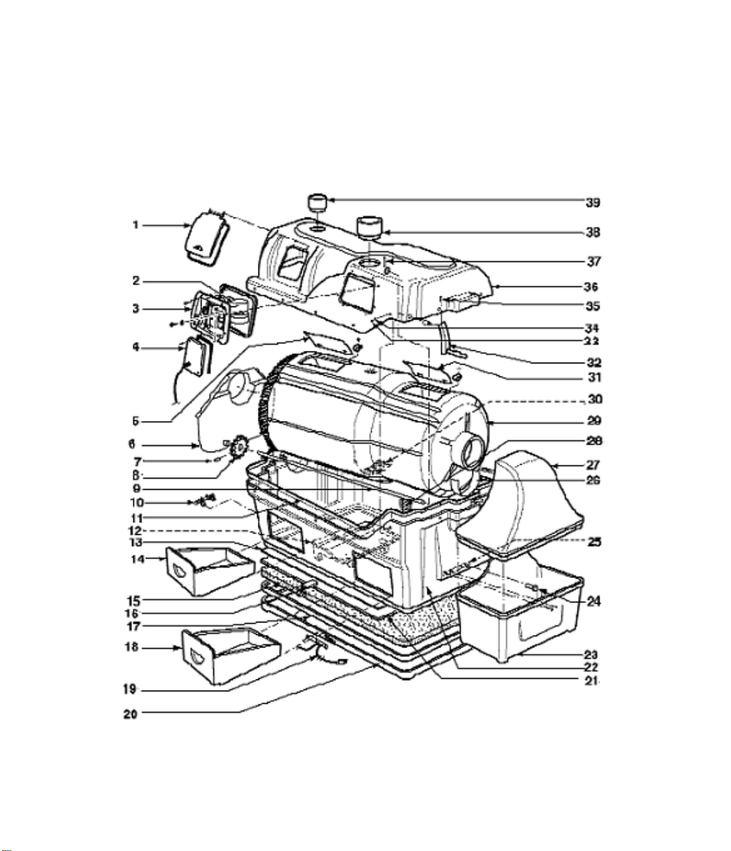
CENTREX 3000 FAMILY PART NUMBERS & DESCRIPTIONS
# PART DESCRIPTION # PART DESCRIPTION
1 AO-DRUMD-0481XX Centrex 3000 Access Door 22 PF-TNAK3-0831XX Centrex 3000 Tank
2 AO-FAN_A-0315KY Fan (Electric and AC/DC) 23 PP-DOBBO-0000XX Collection Bin Bottom
3 AO-FAN_A-0315KY Fan Assembly Housin (Electric and AC/DC ) 24 PP-SCRE0-0580XX Drum Locker Thumb Screw
4 AO-FAN_A-0315KY Plastic Fan Motor Cover (Electric and AC/DC) 25 PF-LOCK3-0836XX Drum Locker
5 PP-DRUMD-0846XX Centrex 3000 Drum Door 26 PP-BEARS-0787CX Drum Bearing Strip
6 Centrex 3000 Bearing Plate 27 PP-DOGTO-0000XX Collection Bin Top
7 PM-ROLLP0-0216XX Roll Pin 28 PP-INTAV-0797XX 3” (75mm) Air Intake
8 AO-SMALL-0440XX Nylon Drive Gear 29 PP-DRUM0-0837XX Centrex 3000 Drum
9 AO-SHAFA-0853XX Centrex 3000 Shaft Assembly 30 PM-DRUMS-0194XX Drum Screen
10 AP-DRAI0-0306XX 1” (25mm)Drain Assembly 31 PP-DRUMD-0846XX Centrex 3000 Drum Door
11 PP-GASK0-0188BX Rubber U Channel 32 AO-HAND0-0307BX Handle
12 PF-EVAPT-0789XX Evaporation Tray 33 PP-WASH0-0274XX Washer Pastic CSK
13 PM-ALUMS-0811XX Aluminum Sheet (Electric and AC/DC) 34 PM-SCREW-0251XX Screw #8 X 5/8" SS
14 PF-DRAW3-0746CX Centrex 3000 Drawer 35 PM-SCREW-0554XX Set Screw
15 PP-INSU0--187XX Insulation(Electric and AC/DC) 36 PF-TOPC3-0832CX Centrex 3000 AC/DC Top
16 AO-THER-0310GX Thermostat (Electric and AC/DC) 36
17 PP-GASK0-0188BX Rubber U Channel 36
18 PF-DRAW3-0746CX Centrex 3000 Drawer 37 PM-ROLLP-0216XX Roll Pin
19 PO-CORD0-0181XX Power Cord 38 AO-PIPEP-0305XX 4” (100ml) Vent Inlet (AC/DC & NE)
20 PF-HEAT3-0833XX Centrex 3000 Heating Tray
21 AO-HEATE-0311XX Centrex 3000 Heating Element (Electric and AC/DC)
PF-TOPC3-0832XX Top Centrex 3000
PF-TOPC3-0833XX Centrex 3000 NE Top
39 PP-INLEP-0207CX Centrex Waste Inlet
- 4 - - 25 -
- 5 -- 24 -
EXPLOSION DRAWING OF COMPOSTING UNIT

Chapter 1
Inspection
This chapter describes how to inspect your new Centrex 3000 prior to installation for damage and make
sure you have received all of the parts.
Check for
Damage
Check Carton
Contents
and
Familiarize
Yourself with
the
Centrex 3000
i) If there is any visible damage to the carton-
the contents of carton MUST be inspected before signing bill of lading. Damaged units
should be refused. Call Sun-Mar immediately.
Before signing the shipping papers and dismissing the driver.-
ii)
ensure that the carton contents have been inspected.
iii)
If the shipper has left-
Report the damage immediately to the transport company and call Sun-Mar.
iv) Soon after delivery, remove the Centrex 3000 carefully
from the carton
-
If there is hidden damage, or for any service Questions, contact Sun-Mar to determine
the best course of action.
Check that the carton contains the vent stack (pipe, fittings, roof flashing and diffusor);
“Compost Sure”, rake, drain hose and fittings, etc. Notify Sun-Mar if you are missing anything.
i) Turn the drum handle clockwise to rotate the Bio-Drum for mixing and aeration. (The drum
rotates counter-clockwise and the drum door closes).
TThhiiss iiss hhooww yyoouu wwiillll rroottaattee tthhee ddrruumm..
ii) Lift and remove the access door and rotate the drum until the drum opening is opposite
the access door for adding “Compost Sure Blue”.
TThhiiss iiss hhooww yyoouu wwiillll aadddd ““CCoommppoosstt
SSuurree BBlluuee””ppeeaatt mmoossss mmiixxttuurree ttoo tthhee ddrruumm
iii) Plug the unit’s electrical cord into a standard three-prong electrical outlet, and feel the air
movement from the vent outlet at the top left of the unit to ensure the vent system is
working properly.
v) Pull out the compost finishing drawers at the bottom left and right of the unit.
vi) After the unit has been plugged in for ten minutes(Electric and AC/DC units) , place a hand
on the floor of the evaporating chamber (the inside floor of the unit) to check it is warm
to the touch, and that the heater is working properly.
vii) Affix the “WARNING/CLEANING” sticker to the underside of the toilet seat cover, and check
that another is on the access port of the composting unit.
Placement of
Unit
The unit should be installed so that the base is protected from weather. The rubber “u” channel at the bottom of the unit is well-sealed with silicone, but if the unit is sitting in water, has
snow melting against it, or rain pouring on it, this may eventually wear through and short out
the heating element. Install your unit with a protective cover of some kind around this area,
and do not install the unit in a pit where water can accumulate around it.
- 7 -
Chapter 2
Installation
ROUGH IN DIMENSIONS
Included
In Your Kit
1- Owners Manual 1- 1 1/2” (38mm)Roof Flashing (Electric & AC/DC)
1- Warranty Card 1- 4” (100mm)Roof Flashing (NE & AC/DC)
1- Evaporation Tray 6- 2” x 30” (50x760mm)PVC Pipe (Electric & AC/DC)
1- 8’ 4” (254cm)Drain Pipe 2- Compost Sure Blue
1- Rake 1- 4” Diffusor (100mm)(Electric & AC/DC)
1- 3” (75mm)Centrex 2000 Inlet 1- 6” (150mm) Diffusor (NE & AC/DC)
5- 4” x30” (100x 700mm)PVC Pipe (NE & AC/DC) 1- Centrex 3000 Hardware Kit
1- 12 Volt 2.4 Watt Fan (NE & AC/DC) 1- Centrex NE Hardware Kit (NE & AC/DC)
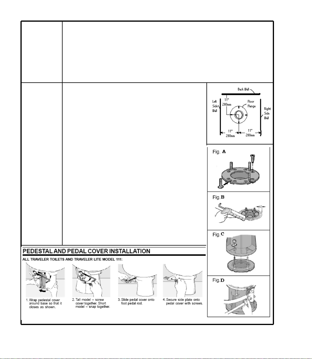
Installing the
“1 Pint” Low
Flush Toilet
1. Make sure the center of the floor flange is at least 11 inches
(280mm) from the back wall.
2. When Installing a new floor flange, make certain that the toilet
mounting bolts align properly with Sealand Traveler toilet mounting pattern.
3. Secure flange to floor using flat head screws through countersunk holes in flange. Insert bolts into slotted holes in flange
(Fig. A)
4. If toilet is being installed in a shower stall, apply a 1/4”(6mm) thick
by 3/4”(19mm) wide bead of glazing compound around the
circumference of the floor flange (Fig B).
5. Position floor seal by pressing the floor bolts up through the
holes in the seal.
6. Set toilet in place with bolts protruding up through mounting holes
in base (Fig C).
7. Install washers and hex nuts provided with toilet. Tighten nuts
down equally with standard 7/17” (12mm) open end wrench.
Remove excess Glazing compound from around base.
8. Connect water supply line to water valve (1/2” or 13mm MPT) inlet
using appropriate fittings (Fig D)
9. Turn on water supply and flush toilet to test for leaks.
10. Attach pedestal and pedal covers to toilet base. See instructions
below.
- 8 - - 21 -
 Loading...