

Sun-Mar centrex 2000 af, centrex 2000 af ac/dc, centrex 2000 af ne Owner's Manual
Serial # ________________
CENTREX 2000 AF FAMILY
OWNER’S MANUAL
PO-MANU0-0829EX
March 2008
Rev D3
Product Info: (905) 332-1314 Fax: (905) 332-1315 Tech. Service: (888) 341-0782
E-mail: compost@sun-mar.com http://www.sun-mar.com
600 Main St 5370 South Service Rd.
Tonawanda NY Burlington, ON
14150-0888 USA L7L 5L1 CANADA
RATED CAPACITY
Weekend & Vacation Use
(Cottage Use)
NE Units; 5 Adults or families of 7 or
Electric Units; 6 Adults or families of 8
Residential & Continuous Use
NE units; 3 Adults or a family of 5 or
Electric Units; 4 Adults or families of 6
Standard 41
Certified for liquid containment,
odors, and solid end products in
both residential and cottage use
Certified to NSF/ANSI Standard 41
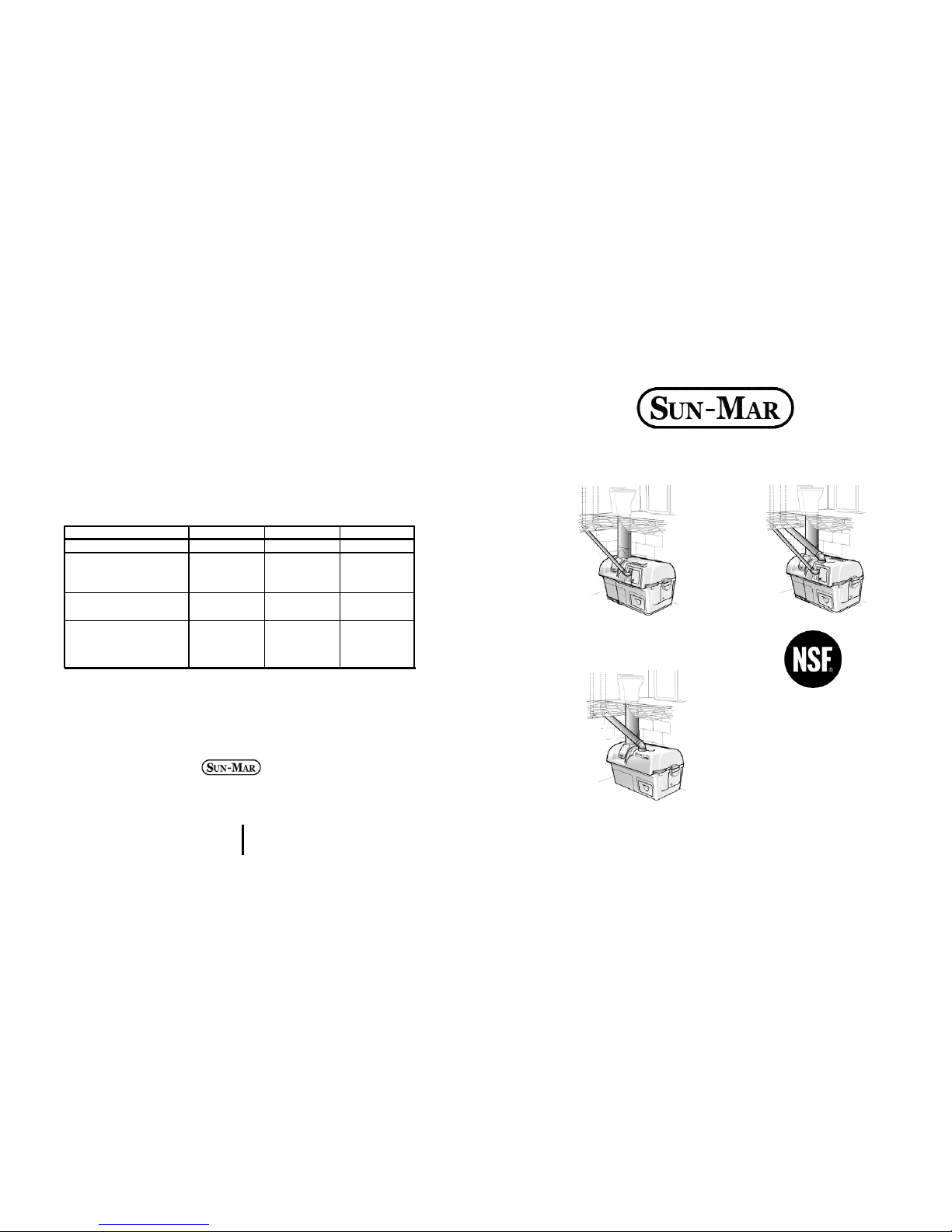
CENTREX 2000 AF
CENTREX 2000 AF AC/DC
CENTREX 2000 AF NE
Electrical Specifacations 2000 2000 NE 2000
AC/DC
Maximum Amps 2.4 NA 2.4/NA
Fan Watts
35 req. 1.4 opt.
(Required or Optional 35 req./
Hook-up) 1.4 opt.
Heater Watts
370 NA 370
(When on)
Average Power Use 200 NA 200
In Watts (Heater on
1/2 time)

- 34 -

- 33 - - 2 -
OWNER’S MANUAL
CONTENTS
Chapter 3
Chapter 4
Chapter 5
I
ntroduction
Chapter 1
Chapter 2
How your composting
toilet Works
How Composting Works
The Composting Chamber
Compost Finishing Drawer
Evaporation Chamber
Winter Use
CENTREX 2000 AF Family Explosion
Drawing
CENTREX 2000 AF Family
Part Numbers
Wiring Diagram
Dry Toilet Explosion Diagram
Inspection
Check for Damage
Check for Parts and Functionality
Placement of AF Dr y Toilet
Installation
CENTREX 2000 AF
Rough in Dimensions
AF Dry Toilet Rough In Dimensions
Included in Your Kit
Installing the AF Toilet Base
The Transition Piece
Determining if an Extention Pipe
Piece is Needed
Assembling Extension Pipe Pieces
Finishing the AF Toilet Installation
Adjusting the Air Intake
Installing optional Vent on Toilet
Cutting Holes in the Toilet Chute
Drain Installation
Handling Effluent
Vent Piping Location
Adjusting the Fan Gate
Vent Piping Installation
Leading the Vent Through the Roof
The Diffusor
Electrical Considerations
12 Volt Fan Installation
3-7
3
3
3
4
4
5
6
6
7
8
8
8
8
9-15
9
10
11
11
11
12
12
12
13
13
13
13
14
14
14
14
15
15
15
16
Start Up and Use
Initial System Start Up
Annual Start Up
Periodic Check Up
Ongoing Maintenance
Compost
Troubleshooting
Aerobic Compost Requirements
Compost Too Wet
Compost Too Dry
Waste not Breaking Down
Lumps
Drum Too Full
Flies
Mechanical
Troubleshooting
Urine Odour In Washroom
Occasional Urine Odour Outside
Sewage Odour when drum tur ns
Fan Noisy
Fan Not Working
Liquid Buildup/
Lack of Eva poration
Overflowing Liquid
Heating System Not Working
Liquid In Finishing Drawer
Drum Will Not Stay Vertical
Drum Will Not Turn
Drum Door Not Opening/
Closing
Waste Not Exiting Waste Pipe
Warranty Information
Basic Maintenance
17-19
17
18
18
19
20-23
20
21
21
22
22
22
23
24-29
24
25
25
25
26
26
26
27
28
28
28
29
29
30
31

Introduction
HOW YOUR COMPOSTING TOILET WORKS
Composting is a natural recycling process where human
waste and toilet paper are broken down by microbes
into minerals and converted back to ear th. Heat, oxygen, organic material and moisture are needed to transform this waste into good fertilizing soil, perfect for your
flower beds.
Oxygen is provided by the ventilation system, and by
tumbling of the composting drum. Additional organic
material is introduced by adding a compost bulking mixture. The waste entering the toilet is approximately
90% water content. Any excess liquid which is not
absorbed will collect on the floor of the unit (evaporation chamber) where it may be evaporated into water
vapor and carried back to the atmosphere through the
venting system. The remaining waste material is transformed into an inoffensive ear th-like substance.
The Composting Chamber
The composting chamber is in the form of a Bio-drum
which holds the natural compost heat, provides the necessary mass to maintain a good compost, and is rotated by turning the handle to achieve perfect mixing and
aeration.
During mixing, both the input door and the output doors
will remain closed. When the drum retur ns to the top
dead centre position ready to receive more waste, the
doors will remain open.
A drum stopper, on the right side of the unit (handle
side) automatically holds the Bio-drum in a top dead
center position so that it is always positioned to receive
new material.
To ensure that the compost remains moist, but does not
get too wet (between 40 and 60% moisture content is
ideal), any excess liquid which the compost cannot
absorb drains through a screen in the bottom of the
drum directly onto an evaporating tray beneath the
screen, and from there, overflows into the larger evaporating chamber. The eva porating tray can be removed
periodically to remove peat moss debris that has accumulated.
Compost Finishing Drawer
The compost finishing drawer is at the extreme right of
the unit below the composting drum, and just above the
evaporating chamber. Compost from the drum is isolated in the drawer where it is allowed to ‘finish’ composting. For seasonally used units, several drawer s of
finished compost are normally removed at the beginning of the season. Otherwise some composted material can be extracted into the drawer and left there for
2 months until it is time to remove more compost from
the drum.
Evaporating Chamber
The third chamber is the floor of the Sun-Mar “CENTREX 2000 AF” which forms the evapor ation chamber
from where excess liquids are evapor ated. You will frequently see liquid in this area.
- 3 - - 32 -
The key to the success of the “CENTREX 2000 AF Family” lies in it’s three chamber design. Each of the three chambers; composting, compost finishing, and evaporation have their own independent environments for optimum efficiency.
In Electric or AC/DC units, air is pulled through intake
holes at the rear of the unit and down the toilet; over
the evaporating chamber, and up the 2”(50mm) vent
stack which exits from the front of the composting unit
when AC power is being used.
When using the NE or AC/DC units and AC power is
unavailable, natural draught caused by the chimney
effect combined with a 12 volt fan draws air into the unit
and up the 100mm vent stack.
In Electric or AC/DC units using the AC mode, the evaporation process is further assisted by a thermostatically controlled heating element in a separate sealed compartment under the evaporating chamber. This heater
is on when there is liquid in the evaporating chamber,
and largely off when the chamber is dry. The heating
system maintains warmth in the evaporating chamber,
and the indirect warmth assists the composting
Winter Use
Because “Sun-Mar” units are made of fiberglass and
high grade stainless steel, freezing temperatures will
not damage the composting unit. Composting action
decreases as the temperature drops, so for extended
use, the toilet should be kept constantly at or above
55-60 F(13-15 C) degrees. All exposed 2“(50mm)
vent stack should be insulated to minimize the condensation in the pipe and avoid ice blockages.
In extreme temperatures, an additional source of heat
will also be required. It is also advisable for residential
applications in extreme climates to install an electric
plumbing tape inside the 2”(50mm) vent to prevent
icing.
If the compost is frozen in the dr um, the unit may be
used periodically as a “holding tank”, until the compost
warms up and the microbes emerge from dor mancy.
Space should be made in the drum to accommodate
winter use. The drum should NOT be rotated when the
compost is frozen.
- 4 -- 31 -
Basic Maintenance Instructions
Sealand toilet and 'Centrex Family' Central Units
The toilet is porcelain and should be cleaned with hot water or bio-degradable products to avoid damage
to the compost. If required 'Compost Quick' or Baking Soda can be used diluted in hot water.
Three times a week weekly maintenance:
Turn drum to reveal waste inlet hole through access por t and add compost mix at the rate of 1 cup
(250ml) per person per day. (Scoop provided is 2 cups or 500ml)
Rotate handle clockwise to mix contents of Bio-drum and give 6 complete revolutions of the drum - (3640 rotations of the handle). Ensure that the drum door opening is in the vertical position at the end
after hearing the 'click' of the catch.
Check compost volume and condition in Bio-ddrum
and:
If the waste in the Bio-drum is too wet add wood shavings to improve aeration.
If composting is too slow add a compost accerant every second week, and ensure that the dr um is not
more than 1/2 full. If it is, follow the instructions for the emptying cycle.
Monthly maintenance and emptying cycle:
Rake out evaporation chamber with rake provided. For units with one, (Centrex 1000, 2000, & 3000
units) the black evaporating tray should be removed, solid matter tipped into the finishing tray and then
replaced beneath the drum screen.
Empty out the collection chamber ready to receive fresh material.
Attention: the composting unit must remai
n plugged in to an electrical outlet continuously to function
odourlessly. The AC/DC units should have both fans running while used in electric mode to prevent recirculation
between vent stacks. If you will be away from the residence where the composting unit is
installed for longer than three days, the power may be disconnected while the composting unit lays dormant.
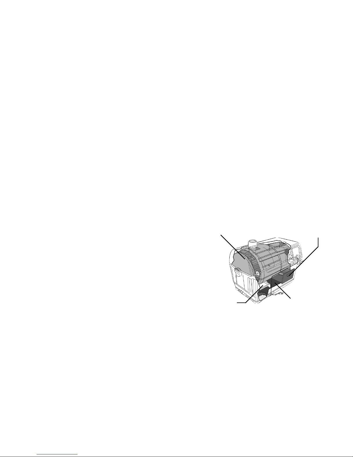
Composting Drum: Waste and
bulking mixture collect for
decomposition
Finishing Drawer: Where
compost is put to ‘finish’
Evaporation Tray: Extends the
surface area of the evaporation chamber
Evaporation Chamber: This is
where you will frequently see liquid collecting.
- 5 - - 30 -
WARRANTY
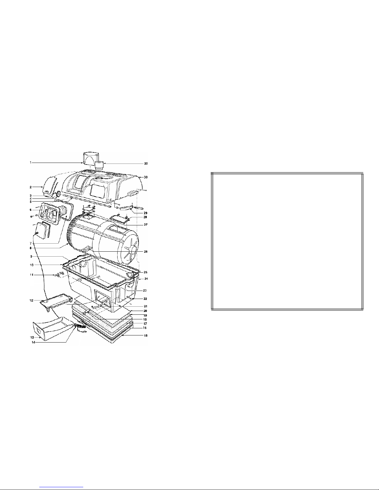
EXPLOSION DRAWING OF COMPOSTING UNIT
SUN-MAR Corp. warrants the original purchaser that this toilet is free from defects in material and workmanship under normal house or cottage use. SUN-MAR Corp. will furnish new
parts for any par t that fails within three years provided that our inspection shows that
such failure is due to defective material or workmanship. Any part supplied by us to
replace another part is warranted for the balance of the original warranty period.
This warranty does not cover:
1. Damage resulting from neglect, abuse, accident or alteration; or damage caused by
fire, flood, acts of God or any other casualty.
2. Parts and accessories not sold or manufactured by SUN-MAR Corp. or any damage
resulting from the use of such items.
3. Damage or failure resulting from failure of the purchaser to follow normal operating
procedure outlined in the Owner’s Manual or in any other printed instructions.
4. Labor and services charges incurred in the removal and replacement of any par ts
found defective under the terms of this warranty.
5. All returns to the factory must by made freight prepaid. All shipments from the factory
are made F.O.B. the factory.
This warranty is in lieu of all other warranties expressed or implied, and no per son is
authorized to enlarge our warranty responsibility, which is limited to the terms of this certificate. The Company reserves the right to change, improve or modify its products without
obligation to install these improvements on equipment previously manufactured.
 Loading...