

Page 1
Serial # ________________
CENTREX 2000 AF FAMILY
OWNER’S MANUAL
PO-MANU0-0829EX
March 2008
Rev D3
Product Info: (905) 332-1314 Fax: (905) 332-1315 Tech. Service: (888) 341-0782
E-mail: [email protected] http://www.sun-mar.com
600 Main St 5370 South Service Rd.
Tonawanda NY Burlington, ON
14150-0888 USA L7L 5L1 CANADA
RATED CAPACITY
Weekend & Vacation Use
(Cottage Use)
NE Units; 5 Adults or families of 7 or
Electric Units; 6 Adults or families of 8
Residential & Continuous Use
NE units; 3 Adults or a family of 5 or
Electric Units; 4 Adults or families of 6
Standard 41
Certified for liquid containment,
odors, and solid end products in
both residential and cottage use
Certified to NSF/ANSI Standard 41
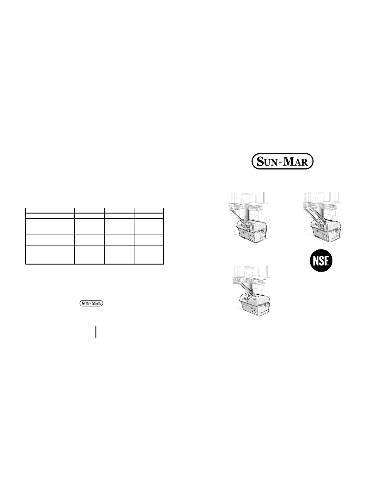
CENTREX 2000 AF
CENTREX 2000 AF AC/DC
CENTREX 2000 AF NE
Electrical Specifacations 2000 2000 NE 2000
AC/DC
Maximum Amps 2.4 NA 2.4/NA
Fan Watts
35 req. 1.4 opt.
(Required or Optional 35 req./
Hook-up) 1.4 opt.
Heater Watts
370 NA 370
(When on)
Average Power Use 200 NA 200
In Watts (Heater on
1/2 time)
Page 2

- 34 -
Page 3

- 33 - - 2 -
OWNER’S MANUAL
CONTENTS
Chapter 3
Chapter 4
Chapter 5
I
ntroduction
Chapter 1
Chapter 2
How your composting
toilet Works
How Composting Works
The Composting Chamber
Compost Finishing Drawer
Evaporation Chamber
Winter Use
CENTREX 2000 AF Family Explosion
Drawing
CENTREX 2000 AF Family
Part Numbers
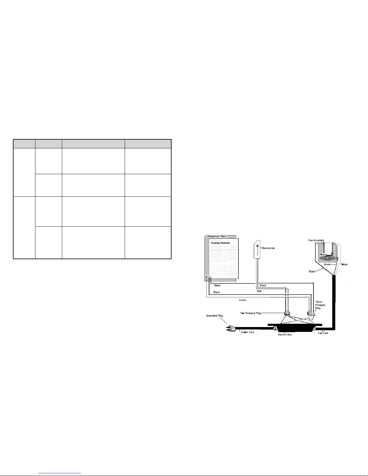
Wiring Diagram
Dry Toilet Explosion Diagram
Inspection
Check for Damage
Check for Parts and Functionality
Placement of AF Dr y Toilet
Installation
CENTREX 2000 AF
Rough in Dimensions
AF Dry Toilet Rough In Dimensions
Included in Your Kit
Installing the AF Toilet Base
The Transition Piece
Determining if an Extention Pipe
Piece is Needed
Assembling Extension Pipe Pieces
Finishing the AF Toilet Installation
Adjusting the Air Intake
Installing optional Vent on Toilet
Cutting Holes in the Toilet Chute
Drain Installation
Handling Effluent
Vent Piping Location
Adjusting the Fan Gate
Vent Piping Installation
Leading the Vent Through the Roof
The Diffusor
Electrical Considerations
12 Volt Fan Installation
3-7
3
3
3
4
4
5
6
6
7
8
8
8
8
9-15
9
10
11
11
11
12
12
12
13
13
13
13
14
14
14
14
15
15
15
16
Start Up and Use
Initial System Start Up
Annual Start Up
Periodic Check Up
Ongoing Maintenance
Compost
Troubleshooting
Aerobic Compost Requirements
Compost Too Wet
Compost Too Dry
Waste not Breaking Down
Lumps
Drum Too Full
Flies
Mechanical
Troubleshooting
Urine Odour In Washroom
Occasional Urine Odour Outside
Sewage Odour when drum tur ns
Fan Noisy
Fan Not Working
Liquid Buildup/
Lack of Eva poration
Overflowing Liquid
Heating System Not Working
Liquid In Finishing Drawer
Drum Will Not Stay Vertical
Drum Will Not Turn
Drum Door Not Opening/
Closing
Waste Not Exiting Waste Pipe
Warranty Information
Basic Maintenance
17-19
17
18
18
19
20-23
20
21
21
22
22
22
23
24-29
24
25
25
25
26
26
26
27
28
28
28
29
29
30
31
Page 4

Introduction
HOW YOUR COMPOSTING TOILET WORKS
Composting is a natural recycling process where human
waste and toilet paper are broken down by microbes
into minerals and converted back to ear th. Heat, oxygen, organic material and moisture are needed to transform this waste into good fertilizing soil, perfect for your
flower beds.
Oxygen is provided by the ventilation system, and by
tumbling of the composting drum. Additional organic
material is introduced by adding a compost bulking mixture. The waste entering the toilet is approximately
90% water content. Any excess liquid which is not
absorbed will collect on the floor of the unit (evaporation chamber) where it may be evaporated into water
vapor and carried back to the atmosphere through the
venting system. The remaining waste material is transformed into an inoffensive ear th-like substance.
The Composting Chamber
The composting chamber is in the form of a Bio-drum
which holds the natural compost heat, provides the necessary mass to maintain a good compost, and is rotated by turning the handle to achieve perfect mixing and
aeration.
During mixing, both the input door and the output doors
will remain closed. When the drum retur ns to the top
dead centre position ready to receive more waste, the
doors will remain open.
A drum stopper, on the right side of the unit (handle
side) automatically holds the Bio-drum in a top dead
center position so that it is always positioned to receive
new material.
To ensure that the compost remains moist, but does not
get too wet (between 40 and 60% moisture content is
ideal), any excess liquid which the compost cannot
absorb drains through a screen in the bottom of the
drum directly onto an evaporating tray beneath the
screen, and from there, overflows into the larger evaporating chamber. The eva porating tray can be removed
periodically to remove peat moss debris that has accumulated.
Compost Finishing Drawer
The compost finishing drawer is at the extreme right of
the unit below the composting drum, and just above the
evaporating chamber. Compost from the drum is isolated in the drawer where it is allowed to ‘finish’ composting. For seasonally used units, several drawer s of
finished compost are normally removed at the beginning of the season. Otherwise some composted material can be extracted into the drawer and left there for
2 months until it is time to remove more compost from
the drum.
Evaporating Chamber
The third chamber is the floor of the Sun-Mar “CENTREX 2000 AF” which forms the evapor ation chamber
from where excess liquids are evapor ated. You will frequently see liquid in this area.
- 3 - - 32 -
The key to the success of the “CENTREX 2000 AF Family” lies in it’s three chamber design. Each of the three chambers; composting, compost finishing, and evaporation have their own independent environments for optimum efficiency.
Page 5
In Electric or AC/DC units, air is pulled through intake
holes at the rear of the unit and down the toilet; over
the evaporating chamber, and up the 2”(50mm) vent
stack which exits from the front of the composting unit
when AC power is being used.
When using the NE or AC/DC units and AC power is
unavailable, natural draught caused by the chimney
effect combined with a 12 volt fan draws air into the unit
and up the 100mm vent stack.
In Electric or AC/DC units using the AC mode, the evaporation process is further assisted by a thermostatically controlled heating element in a separate sealed compartment under the evaporating chamber. This heater
is on when there is liquid in the evaporating chamber,
and largely off when the chamber is dry. The heating
system maintains warmth in the evaporating chamber,
and the indirect warmth assists the composting
Winter Use
Because “Sun-Mar” units are made of fiberglass and
high grade stainless steel, freezing temperatures will
not damage the composting unit. Composting action
decreases as the temperature drops, so for extended
use, the toilet should be kept constantly at or above
55-60 F(13-15 C) degrees. All exposed 2“(50mm)
vent stack should be insulated to minimize the condensation in the pipe and avoid ice blockages.
In extreme temperatures, an additional source of heat
will also be required. It is also advisable for residential
applications in extreme climates to install an electric
plumbing tape inside the 2”(50mm) vent to prevent
icing.
If the compost is frozen in the dr um, the unit may be
used periodically as a “holding tank”, until the compost
warms up and the microbes emerge from dor mancy.
Space should be made in the drum to accommodate
winter use. The drum should NOT be rotated when the
compost is frozen.
- 4 -- 31 -
Basic Maintenance Instructions
Sealand toilet and 'Centrex Family' Central Units
The toilet is porcelain and should be cleaned with hot water or bio-degradable products to avoid damage
to the compost. If required 'Compost Quick' or Baking Soda can be used diluted in hot water.
Three times a week weekly maintenance:
Turn drum to reveal waste inlet hole through access por t and add compost mix at the rate of 1 cup
(250ml) per person per day. (Scoop provided is 2 cups or 500ml)
Rotate handle clockwise to mix contents of Bio-drum and give 6 complete revolutions of the drum - (3640 rotations of the handle). Ensure that the drum door opening is in the vertical position at the end
after hearing the 'click' of the catch.
Check compost volume and condition in Bio-ddrum
and:
If the waste in the Bio-drum is too wet add wood shavings to improve aeration.
If composting is too slow add a compost accerant every second week, and ensure that the dr um is not
more than 1/2 full. If it is, follow the instructions for the emptying cycle.
Monthly maintenance and emptying cycle:
Rake out evaporation chamber with rake provided. For units with one, (Centrex 1000, 2000, & 3000
units) the black evaporating tray should be removed, solid matter tipped into the finishing tray and then
replaced beneath the drum screen.
Empty out the collection chamber ready to receive fresh material.
Attention: the composting unit must remai
n plugged in to an electrical outlet continuously to function
odourlessly. The AC/DC units should have both fans running while used in electric mode to prevent recirculation
between vent stacks. If you will be away from the residence where the composting unit is
installed for longer than three days, the power may be disconnected while the composting unit lays dormant.
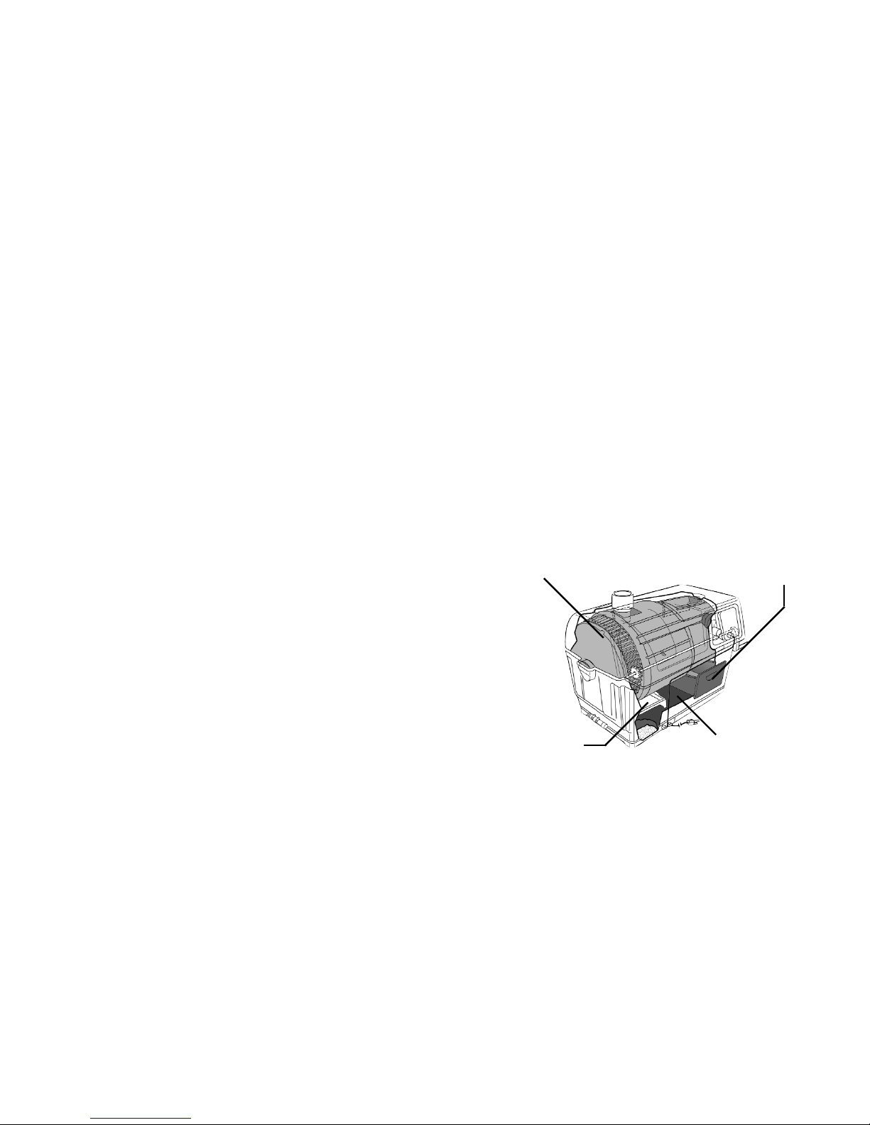
Composting Drum: Waste and
bulking mixture collect for
decomposition
Finishing Drawer: Where
compost is put to ‘finish’
Evaporation Tray: Extends the
surface area of the evaporation chamber
Evaporation Chamber: This is
where you will frequently see liquid collecting.
Page 6
- 5 - - 30 -
WARRANTY
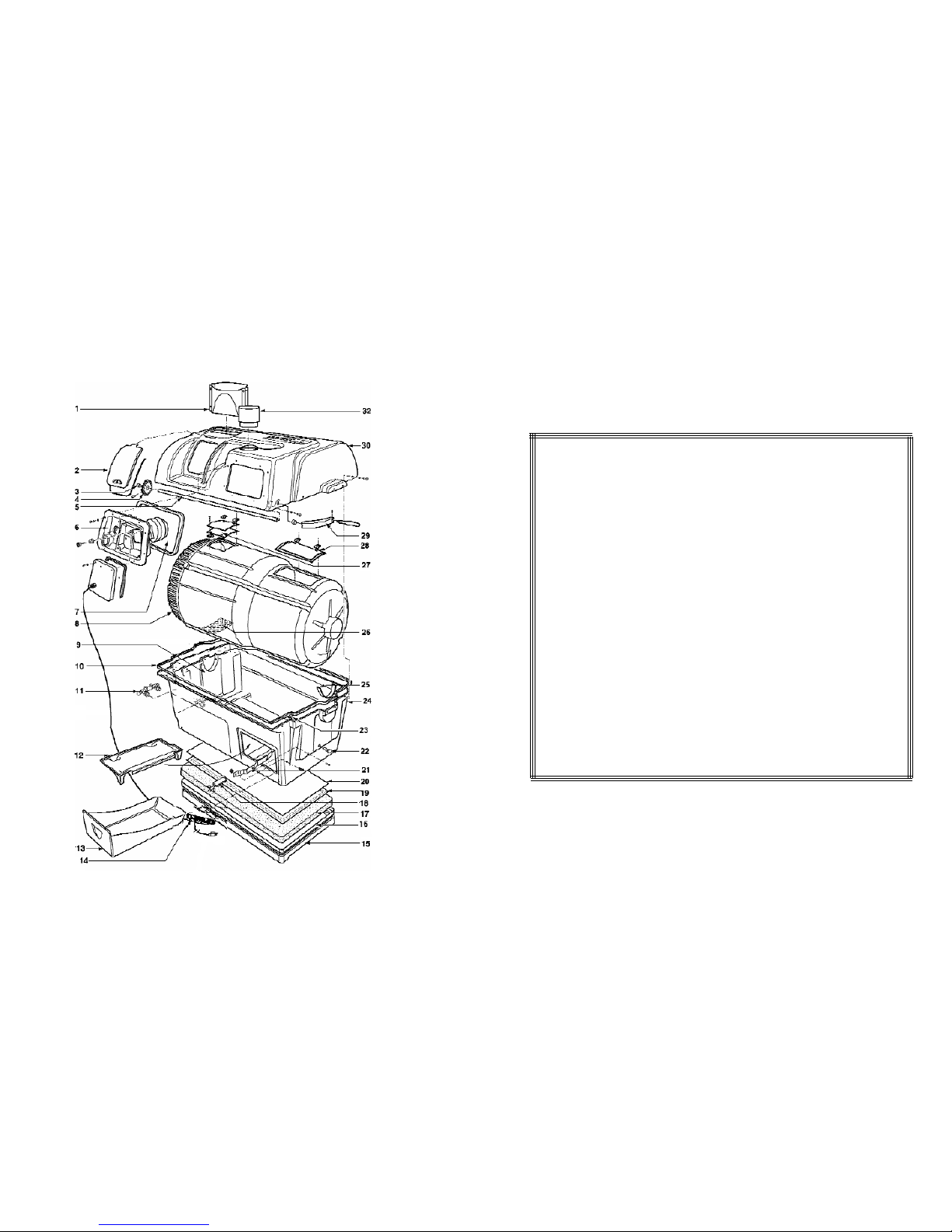
EXPLOSION DRAWING OF COMPOSTING UNIT
SUN-MAR Corp. warrants the original purchaser that this toilet is free from defects in material and workmanship under normal house or cottage use. SUN-MAR Corp. will furnish new
parts for any par t that fails within three years provided that our inspection shows that
such failure is due to defective material or workmanship. Any part supplied by us to
replace another part is warranted for the balance of the original warranty period.
This warranty does not cover:
1. Damage resulting from neglect, abuse, accident or alteration; or damage caused by
fire, flood, acts of God or any other casualty.
2. Parts and accessories not sold or manufactured by SUN-MAR Corp. or any damage
resulting from the use of such items.
3. Damage or failure resulting from failure of the purchaser to follow normal operating
procedure outlined in the Owner’s Manual or in any other printed instructions.
4. Labor and services charges incurred in the removal and replacement of any par ts
found defective under the terms of this warranty.
5. All returns to the factory must by made freight prepaid. All shipments from the factory
are made F.O.B. the factory.
This warranty is in lieu of all other warranties expressed or implied, and no per son is
authorized to enlarge our warranty responsibility, which is limited to the terms of this certificate. The Company reserves the right to change, improve or modify its products without
obligation to install these improvements on equipment previously manufactured.
Page 7
- 6 -- 29 -
CENTREX 2000 A/F PART NUMBERS & DESCRIPTIONS
Not a common repair.
Follow items in prevention column
for “Drum Too Full”
Drum should never be more than
1/2 full.
Symptom Cause Remedial Action Prevention
# PART DECSRIPTION # PART DESCRIPTION
1.
PP-AIRFL-0005XX AF Transition Piece
17
PP-INSU0-0187XX Insulation (Electric & AC/DC)
2
. AO-ACCEP-0481BX Access Port
18
AO-THERA-0001BX Thermosat Sweden
3.
PM-BUSH0-0173 Bushing 1/2”(13mm) OD
18
AO-THERA-0001AX Thermostat
4.
PP-GEAR0-0173XX Nylon Drive Gear
19
AO-HEATE-0311XX Heating Element C9286-1
5
AO-SHAFA-0852XX Stainless Steel Drive Shaft
20
PM-ALUMS-0811XX Aluminum Sheet
6
AO-FAN_A-0315KX Fan Assembly (Electric & AC/DC)
21
AO-DRUML-0469BX Drum Locker
7
PP-FAN_a-0315DD Rubber Gasket
22
PP-SCRE0-0827XX Drum Lock Release Knob
8
PP-DRUM0-0800XX Centrex 2000 Drum
23
PP-GASK0-0188BX Rubber U Channel
9
PP-BEARP-0758RX Bearing Plate
24
PF-TANK2-0801XX Centrex 2000 Tank
10
PP-GASK0-0188BX Rubber U Channel
25
PP-BEARS-0787BX Bearing Strip
11
AP-DRAI0-0306XX 25mm Drain Assembly
26
AM-DRUMS-0329XX Drum Screen
12
PF-EVAPT-0789XX Evaporation Tray
27
AO-DRUMD-2004XX Drum Door
13
PF-DRAW1-0764XX Centrex 2000 Drawer
28
AO-DRUMD-2004XX Drum Door
14
P0-ELECB-0001AX Electric Box Assembly(Electric and AC/DC)
29
AO-HANDL-3000XX Swivel Handle
15
PF-HEAT2-0803XX Heater Base (Electric & AC/DC)
30
PP-TOPC2-0802CX Centrex 2000 AC/DC Top
16
PP-GASK0-0188BX Rubber U Channel
30
PP-TOPC2-0802BX Centrex 2000 Top Kit
30
PP-TOPC2-0802DX Centrex 2000 NE Top
31
AO-PIPEP-0305XX 100mm Vent Inlet (NE)
Drum Will
Not Turn
(Cont’d)
Drum Door
Not
Opening/
Closing
Properly
(Compost will
drop into the finishing drawer
even when the
drum is not
being rotated
backwards to
extract compost).
Drum fallen from
bearings fallen.
Drum too full
Hinges Stuck
Hinge(s) broken
Have your serial number ready.
If the dr um has fallen, contact your Sun-Mar
dealer immediately. We will make sure your problem is fixed quickly.
See Section on “Compost Troubleshooting- Drum
Too Full”
Drum hinges have compost caked on them.
Spray with vinegar and water solution and clean
with nylon brush. This will push the obstruction
away so the door swings freely.
Call your Sun-Mar dealer to obtain a replacement
drum hinge.
Page 8
- 7 - - 28 -
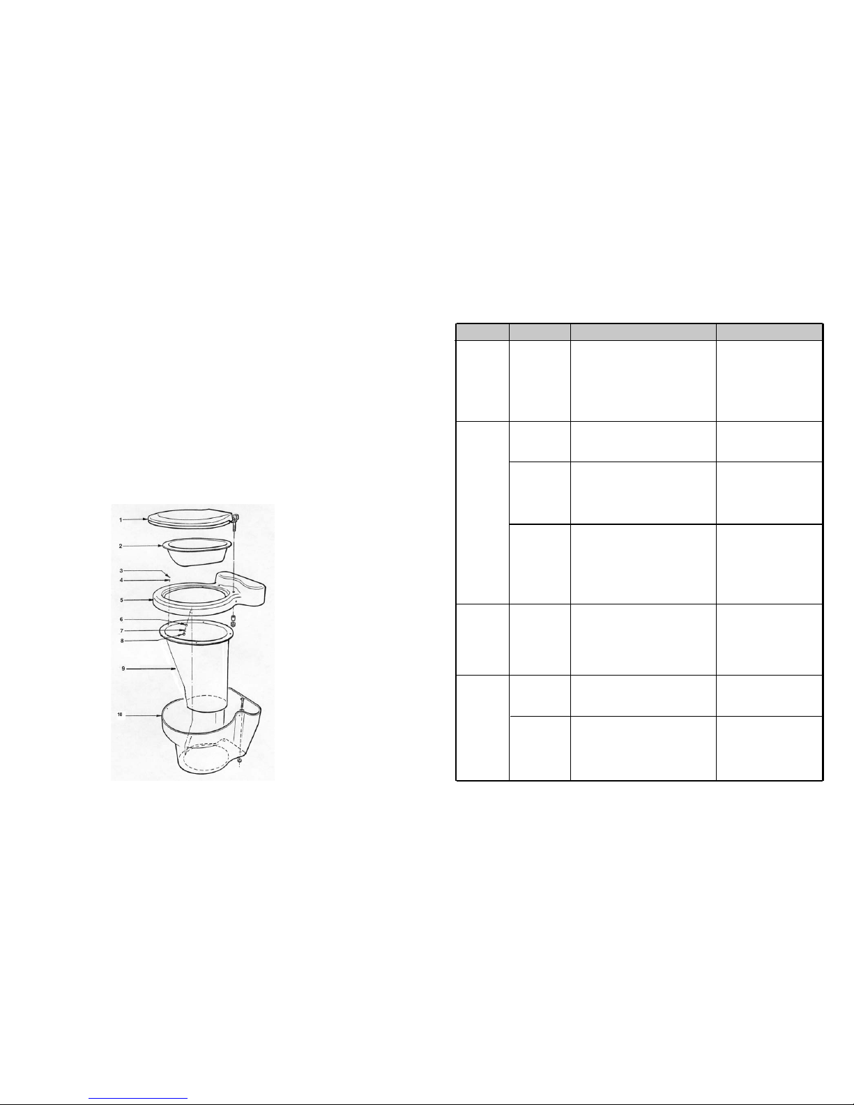
EXPLOSION VIEW & PARTS FOR DRY TOILET
# PART DESCRIPTION
1
PP-TOILS-0208CX Toilet Seat White
PP-TOILS-0208DX Toilet Seat Bone
2
PF-BOWLL-0246FX AF Bowl Liner
3
PP-CAP00-0587XX Tap Cap Bone
PP-CAP00-0587WX Tap Cap White
4
PM-SCRE0-0250XX #8 X 3/4” (19mm) Flat Head
Philips Screw
5
PF-AIRFL-0001BX Toilet Top Bone
PF-AIRFL-0001XX Toilet Top White
# PART DESCRIPTION
6
PM-SCRE0-0251BX #8 X 1/2” (16mm) Stainless
Steel Flat Head Screw
7
PP-WASH0-0274XX CKS Plastic Washer
8
PP-SNAPC-0273XX Snap Cap (Bone)
PP-SNAPC-0273WX Snap Cap (White)
9
PP-AIRFL-003XX Toilet Chute
10
PF-AIRFL-0002BX Toilet Base Bone
PF-AIRFL-0002XX Toilet Base White
Symptom Cause Remedial Action Prevention
Heating
System Not
Working
(Cont’d)
(Electric
and AC/DC)
Liquid in
Finishing
Drawer
Drum Will
Not Stay
Vertical
Drum Will
Not Turn
Heating Element
Failure
Drum Screen
Clogged
Unit tilted to the
right
Condensation running down vent
stack
Drum Locker
Broken
Set screw securing
handle to shaft has
broken
Steel pin securing
gear wheel to shaft
has broken
DO NOT use a pressure hose
around the base of the unit.
Install Unit so that weather and/or
groundwater cannot get at the base
of the unit.
Use Proper Bulking Material
Install toilet level or tilting slightly to
the left, DO NOT install the toilet tilting forwards or to the right. If you
are unsure of the grade of the floor,
install it with a wedge piece.
Remove horizontal sections of vent
pipe and insulate all exposed 2”
(50mm)venting.
When returning the drum to top
dead center position, do not bang
against drum locker with excessive
force. Remember to pull out the
drum locker button before rotating
the drum backwards.
Not a common repair.
Keep composting drum from becoming overloaded. This puts undue
strain on the nylon gear.
Have your serial number ready and call your SunMar dealer for a replacement. (Detailed instructions are included with the replacement par t)
Please note: Because this part is not easy to
replace, and because there is far less chance
that you will need this part than a thermostat; we
recommend trying to replace the ther mostat first.
Use a flashlight to see the screen at the bottom
of the dr um. Scrub screen with wire brush. The
overflow drain should be hooked up.
Use a 1/4 - 1/2”(6mm - 12mm) wedge piece
under the right side of the unit to drain liquid
more easily towards the overflow drain of the
unit.
Liquid will be clear or yellowish in appearance.
Make sure all vent pipe exposed to the outdoor is
well insulated and there are no horizontal runs.
Have serial number ready and call your Sun-Mar
dealer for a replacement part.
Drill out set screw and replace, or get handle
replacement kit (instructions included).
Have your serial number ready and call your SunMar dealer for a replacement Small Gear Kit.
Page 9
- 27 - - 8 -
Symptom Cause Remedial Action Prevention
Drains Blocked
Test to determine
whether failure has
occurred
Thermostat Failure
Overflowing
Liquid
(Cont’d)
Heating
System Not
Working
(Electric
and AC/DC)
Chapter 1
Inspection
Inspecting
the unit for
damage
Check Carton
Contents
and
Familiarize
Yourself with
the
Centrex 2000
A/F
Placement of
AF Dry Toilet
1. Rake peat moss away from back two corners
of Centrex 2000 A/F. These are the“buildup”
areas. If drains are still clogged, proceed to
step 3.
2. Check drain line for kinks, blockages or
upward bends. Remove and flush if blockages
present, unkink if bent and ensur e that the
drain pipe is sloping downward. If your
drain pipe is in order, proceed to step 3.
3. Use a wire to poke peat moss out of the dr ain
assembly at the back. You will notice if this
is clogged because you will see a brown spot
through the opaque assembly. (Only peat
would make it through the drum screen). If
there is no peat clog, or the problems continue, backwash the unit quickly with a hose by
applying the nozzle to one of the drain
assemblies and turning it on and off very
quickly. If the bottom of the unit is full of
liquid, you may wish to remove some prior to
back-washing. A shop-vac works well.
Pull drawer out and put your hand in the evaporation chamber (Not in the liquid). If there is no
warmth rising from the floor of the unit, your
heating system is not working. It is most commonly the thermostat that has failed. If you
notice a lack of ev aporation, but there is still
warmth in the heating chamber, see the Liquid
Buildup section on page 26 for solutions.
Have your serial number ready and call Sun-Mar
for a replacement. (Detailed instructions are
included with the replacement part)
If the insulation behind the ther mostat access
cover is moist or discolored, or heating does not
work after the new thermostat has been connected, then the heating element has failed.
1. A clogged drain is not very likely
to happen if you rake your
evaporating chamber 1-2 times a
season (cottage use) and 3-4
times for continuous use.
2. Use premium 1”(25mm) hose for
the drain line. A good hose will
be less likely to kink. Use elbows
or fittings around bends to preventkinks.
3. Use the proper bulking material.
A ground fault circuit interrupter
(GFI) is recommended to protect
your Centrex 2000 A/F from power
surges that could cause your heating
system to malfunction.
Your thermostat and fan are the two
constantly moving parts on the unit,
and so are the most likely to fail.
Both are easy to replace.
i) If there is any visible damage to the carton-
the contents of carton MUST be inspected before signing bill of lading. Damaged units
should be refused. Call Sun-Mar immediately.
ii)
Before signing the shipping papers and dismissing the driver.-
ensure that the carton contents have been inspected.
iii)
If the shipper has left-
Report the damage immediately to the transpor t company and call Sun-Mar.
iv)
Soon after delivery, remove the Centrex 2000 AF carefully
from the carton
-
If there is hidden damage, or for any service Questions, contact Sun-Mar to
determine the best course of action.
Check that the carton contains the vent stack (pipe, fittings, roof flashing and diffusor); rake,
drain hose and fittings, extension pipe piece and transition piece. Notify Sun-Mar if you are
missing anything.
i) Turn the drum handle clockwise to rotate the Bio-Drum for mixing and aeration. (The drum
rotates counter-clockwise and the drum door closes).
TThhiiss iiss hhooww yyoouu wwiillll rroottaattee tthhee ddrruumm..
ii) Lift and remove the access door and rotate the drum until the drum opening is opposite
the access door for adding a compost bulking mixture.
TThhiiss iiss hhooww yyoouu wwiillll aadddd bbuul
lkkiinngg
mmiixxttuurree ttoo tthhee ddrruumm
iii) Plug the unit’s electrical cord into a standard electrical outlet, and feel the air movement
from the vent outlet at the top left of the unit to ensure the vent system is working prop-
erly (Electrical or AC/DC)
v) Pull out the compost finishing drawers at the bottom left and right of the unit.
vi) After the unit has been plugged in for ten minutes, place a hand on the floor of the
evaporating chamber (the inside floor of the unit) to check it is warm to the touch, and
that the heater is working properly.
vii) Affix the “WARNING/CLEANING” sticker to the underside of the toilet seat cover, and check
that another is on the access port of the composting unit.
viii) Check the AF “Dry Toilet” for any damage.
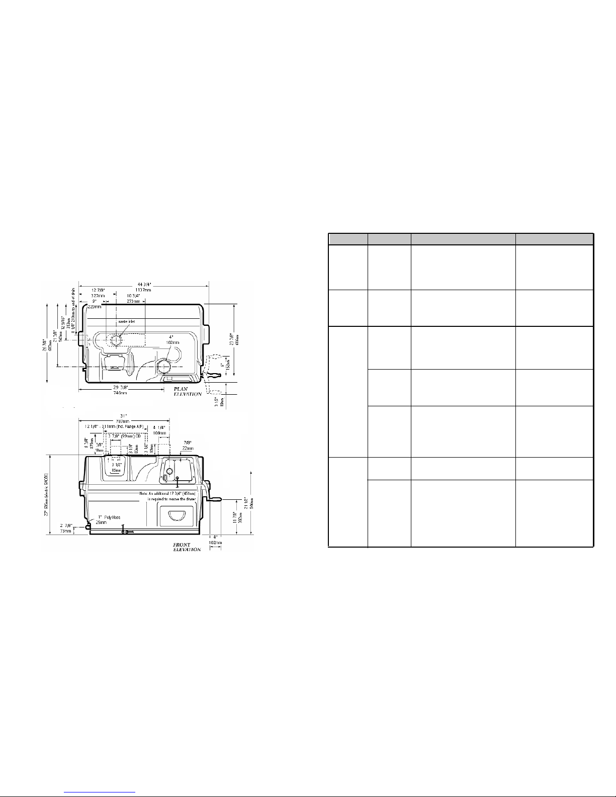
Ensure that the floor joists are not in the way and that there is an unobstructed 10”(254mm)
diameter passage from the underside of the AF “Dr y Toilet” to the top of the transition piece.
The 10”(254mm) hole should be centered 13”(33cm) from the back wall and at least 6.5”
(165mm) from the side wall in the room where the toilet will be installed.
The transition piece on the top of the composting unit should be located so that the center line
of the transition piece is directly below the center of the 10”(254mm) circular cutout which will
be made in the bathroom floor above. The transition piece should be completely ver tical on the
composting unit.
Page 10
- 9 - - 26 -
Symptom Cause Remedial Action Prevention
Fan Noisy
(Cont'd’)
(Electric
and AC/DC)
Fan Not
Working
(Electric
and AC/DC)
Liquid
Buildup/
Lack of
Evaporation
Overflowing Liquid
Fan damaged in
shipping, or bearing
are beginning to
wear if it is rattling.
Debris in fan or
Mechanical Failure.
Increased usage.
Failure of heating
system (Electric and
AC/DC)
Mineral salts may
have accumulated
in the evaporation
chamber over a few
years, reducing
evaporation rates.
Overflow drain not
hooked up
Unit tipped forward
3. If it is a vibration noise, you may need to tie
down the top of the stack with guide wires
and bracket the pipe that runs up the side of
the structure.
Have your serial number ready and call Sun-Mar
The amount of liquid v aries substantially between
installations. The overflow drain needs to be
installed on all Centrex 2000 AF models as you
will have overflow in DC mode and with heavy use
on AC mode.
Check “heating not working”.
To get rid of these, fill the evaporation chamber
with very hot water. Leave overnight.
Drain all Liquid through the overflow drain by tipping the unit up (make sure overflow is hooked
up first)
Connect overflow safety drain (See also increased
usage above)
Check and ensure that the unit is level or tilting
slightly towards the left by placing a 6mm -12mm
shim piece under the right side of the unit.
The fan is a continuously moving
part which will eventually have to be
changed. Do Not turn on and off
daily.
Install the safety drain. If the unit is
being used in DC mode there will be
very little evaporation.
Rake evaporating chamber vigorously at spring startups for cottage
use, and once every other month for
residential use.
ROUGH IN DIMENSIONS
Chapter 2
Installation
Page 11
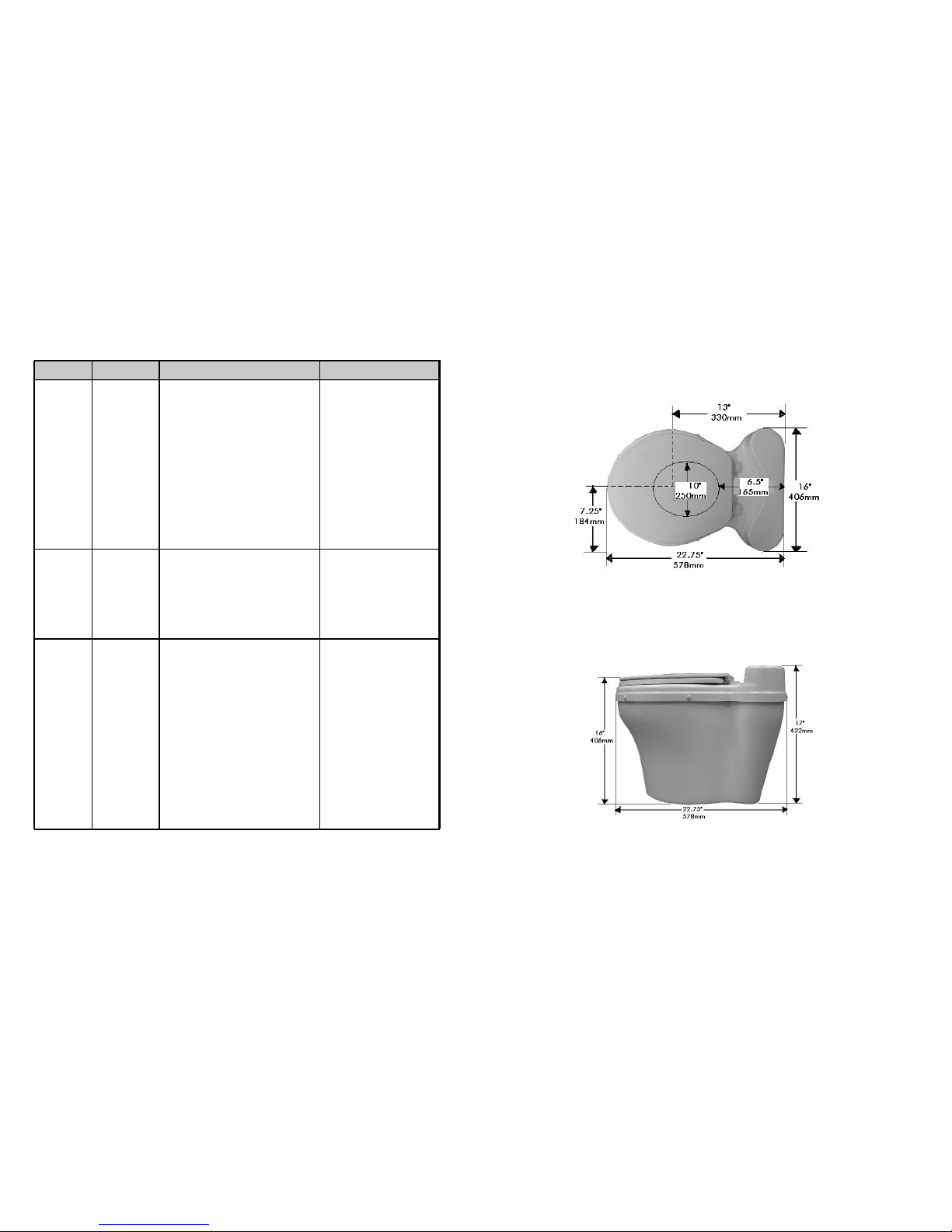
AF “DRY TOILET” ROUGH IN DIMENSIONS
Occasional
Urine
Odour
Outside
Strong
Sewage
Odour
Present
when drum
turns
Fan Noisy
(Electric
and AC/DC)
Downdraft is dependent on wind
direction, as well as natural
obstructions, etc.
Initially, install the vent 20-30”(6090cm) above the peak of the roof.
If symptoms occur, add lime or a filter box.
Follow “Ongoing Maintenance” and
use proper bulking material.
Clean the AC fan with a small brush
and/or compressed air nozzle once
every 2-3 years in cottage use, or
once a year residentially. To do
this, remove the fan assembly by
taking off the snap cap covers and
unscrewing the screws which hold it
in.
The entire assembly will then simply
slide out. This will prevent wear
and lengthen the life of your fan.
Cleaning should not be necessary
for the DC fan.
Symptom Cause Remedial Action Prevention
1. Vent stack not
installed even
with peak of roof.
2. If vent stack is
installed above
roof peak, natural obstructions,
such as tall
trees, being
located in a
valley or close to
a hill may be
causing downdraft.
Compost is
anaerobic
Fan damaged in
shipping, or bearings are beginning
to wear if it is rattling.
1. Check that the vent is installed 20-30”
(60-90cm) above the peak of the roof. If
not, extend the vent. Guide wires may be
necessary.
2. Add lime to the evaporation chamber - as
much as you think necessary. You will have
to rake more often if you do this. You can
also add lime to the compost if desired, but
no more than 1 cup(250ml) per week as it
may upset the PH balance in larger
amounts.
3. Sun-Mar has a filter box available which will
filter the ammonia out of the 50mm stack
vented air in a downdraft situation. Call
Sun-Mar for details.
Begin following: “Compost Troubleshooting” suggestions.
1. If the fan is r attling, it may need to be
cleaned or the bearings are worn and the fan
needs to be replaced.
2. A hum is the normal sound the fan will make.
If you are in a ver y quiet setting it will be
more noticeable. If this is the case, consider
purchasing an AC fan speed control so that
the fan may be turned down when the noise
bothers you. These are not available for our
DC fans, but should not be necessary.
3. If it is a vibration noise, you may need to tie
down the top of the stack with guide wires
and bracket the pipe that runs up the side of
the structure.
- 10 -- 25 -
Page 12
Urine Odour
around
Centrex
2000 AF
Symptom Cause Remedial Action Prevention
Included
In Your Kit
Installing the
AF Toilet
Base
The
Transition
Piece
1- Owners Manual 1- 1 1/2” (38mm)Roof Flashing (Electric & AC/DC)
1- Warranty Card 1 - 4” (100mm)Roof Flashing (NE & AC/DC)
1- Evaporation Tray 6- 2”x30”(51mm x 787mm) PVC Pipe (Electric & AC/DC)
1- 8’4”(256cm x 25 mm) Drain Pipe 1- Centrex 2000 Hardware Kit
1- Rake 1- 4”(100mm) Diffusor (Electric & AC/DC)
1- AF Transition Piece 1- 6”(150mm) Diffusor (NE & AC/DC)
5- 4” x30” (100mm x 785mm) ABS Pipe (NE & AC/DC)
1- Centrex 2000 NE Hardware Kit (NE & AC/DC)
1- 12 Volt 2.4 Watt Fan (NE & AC/DC) 1- 44”(112cm) Extension Pipe Piece
1- AF Silicone Kit
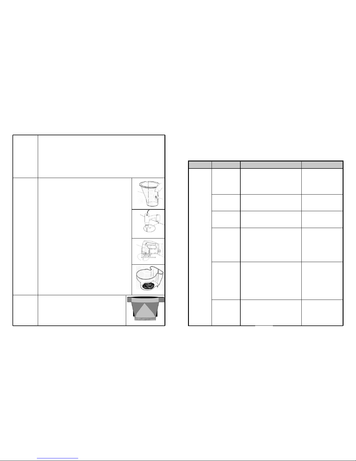
The AF “Dry Toilet” comes preassembled. For the purpose of explanation,
the toilet base is the bottom of the toilet which is secured to the bathroom
floor, the toilet chute is the black inner section (shown in Fig. A) that fits
through the floor and is attached to the toilet top, the toilet top is the upper
part of the toilet that attaches to the toilet base, and the bowl liner which is
the black removable funnel shaped piece below the toilet seat.
To install the AF “Dry Toilet”, follow the procedure outlined below:
1. To locate the position of the hole, place the toilet chute in the desired
location and trace the 10”(250mm) diameter cut out in the bottom of the toilet base on the floor in the bathroom. (See Fig. A)
2. Drill a 1/2”(6mm) hole on the front of traced line and then check under
the floor that the hole will be clear of floor joists and will line up with the composting unit below. (See Fig. B)
3. If the position is cor rect, complete the cutting of the 10”(250mm)
diameter circle with a jig saw. (See Fig. C)
4. Center the toilet base over the 10”(250mm) diameter hole that has been
cut out of the floor and securely attach to the floor by using the four 5/16” by
2 1/2”(8mm by 64mm) lag bolts that are provided with your kit. (See Fig. D)
**Prior to finishing the toilet installation, it is a good idea at this time to do a
pre-assembly check to see if you will need any extension pipe
Place transition piece(Fig. E) into the waste inlet hole on the top of the
Centrex 2000 AF composting unit. Make sure that the transition piece
is completely vertical on the unit, or completely ver tical. It is important
that the transition piece is not tilted so that waste can drop directly into
the composting drum.
Fig. E
Fig. D
Fig. C
Fig. B
Fig. A
Horizontal runs or
downward slopes on
pipe are causing condensate to block
50mm vent pipe.
Fan has failed (AC or
DC mode)
Device other than SunMar diffusor is
installed on top of the
vent stack
Room where unit is
located is airtight.
50mm vent stack has
too many bends
and/or horizontal
lengths.
Not enough air being
pulled down the dry
toilet
Re-install the vent so there are no longer any low
points where condensate can collect. If re-installation is not possible, drill a small hole in the bottom of the low point (prefer ably outdoors) to
allow condensate to drain. (Note: watch for icing
in winter at this hole.)
Have your serial number ready and call Sun-Mar
for a replacement. Instructions are included with
the replacement fan.
Wind turbines or vent caps may be discouraging
air movement. If so, replace with a Sun-Mar dif fusor.
1. Hold a lighter up to the air intake holes on the
back of the unit. Air should be drawn into
the holes. If air is not easily pulled in, check
venting for too many bends or horizontal
lengths and/or provide more ventilation to the
room.
2. Install fresh air intakes on any competing
appliances.
1. Re-install the 2”(50mm) vent stack to reduce
the number of bends/eliminate horizontal
lengths.
2. If the vent stack cannot be fur ther straightened, remove the AC fan assembly and
reduce the amount of r ecirculating air by
adjusting the fan gate (see page 14).
Two 3”(75mm) diameter air intake holes covers
are supplied with the hardware kit. One or both
of the air intake holes at the rear of the unit, may
be covered so that more air is pulled down the
toilet.
Install wall brackets on vent pipe
to prevent settling. DO NOT
install horizontal runs as liquid
will collect and block ventilation,
causing odour.
The fan is a constantly moving
part and has a finite ser vice life.
Wind turbines or vent caps
should not be installed on or,
instead of a Sun-Mar diffusor.
Install your Centrex 2000 AF in
an area with plenty of ventilation and watch for competing
appliances such as bathroom
fans and wood stoves.
Install the vent with minimal
bends (total bends should equal
no more than 360 degrees) and
NO horizontal or downward
slopes.
Covers should only be inserted if
they are needed, because insertion reduces airflow over the
evaporation chamber, which in
turn reduces evapor ation performance.
- 11 -
- 24 -
Most problems are prevented through proper maintenance and the use of proper bulking materials in the toilet. If you
do have a problem which may be a mechanical or installation problem, this Trouble Shooting section will help you solve
it. If you still have further questions, contact technical service at Sun-Mar for advice .
Chapter 5
MECHANICAL TROUBLE SHOOTING
Page 13
- 23 - - 12 -
Symptom Cause Remedial Action Prevention
Flies
Present
-compost too dry
-compost anaerobic
-kitchen/garden
waste added
-foreign material
added
1 .To get rid of flies, you can use any pesticide
that is used on your garden. Pesticides used
for garden use are not anti-bacterial so are
safe to use on your compost. If you prefer not
to use a pesticide in your compost, the unit
should be cleaned out completely and washed
with soapy water to kill any remaining eggs.
Once the unit is washed, it should be rinsed well
to remove all traces of soap before restar ting
the compost.
2. If using a pesticide to kill the insects, it may
be purchased from a local garden center or
hardware store.
3. If using a liquid, sprinkle about 1/2 cup
(125ml) of the mixture dir ectly over the
compost. Using a spr ay bottle, apply through-
out the entire toilet (finishing drawer, evapo-
rating chamber, drum, out side of dr um) until
the fly population is eliminated. Open a
window or door to ventilate the room while
applying and keep children and pets away
from the area for a few hours after
application.
Repeat if you see another fly after the initial
application.
IMPORTANT:
Application of a pesticide in a Sun-Mar composter is not a health concern because all SunMar units are vented.
1. Keep compost moist. In order to
determine a good level of moisture,
shine a flashlight into the drum.
The compost should have a slight
gloss or shine. If it does not, add
warm water to it until it reaches this
consistency. Fungus gnats tend to
be attracted to a dry compost, due
to the fungus which begins to form
on the surface when it dries out. A
good, moist compost will not be
attractive to flies.
2. Do not add topsoil from the
ground, composted matter, or
kitchen scraps to the toilet. Flies
may be present in, or attracted
to these items.
3. If toilet is installed over an old sep
tic line,make sure that the lines are
well sealed. Insects find unused
lines attractive.
4.See “Compost Remediation” if the
compost smells- anaerobic compost
will attract flies and drastically
reduce the performance of your
composting unit
5. Use a mixture of peat moss and
non-antibacterial wood shavings.
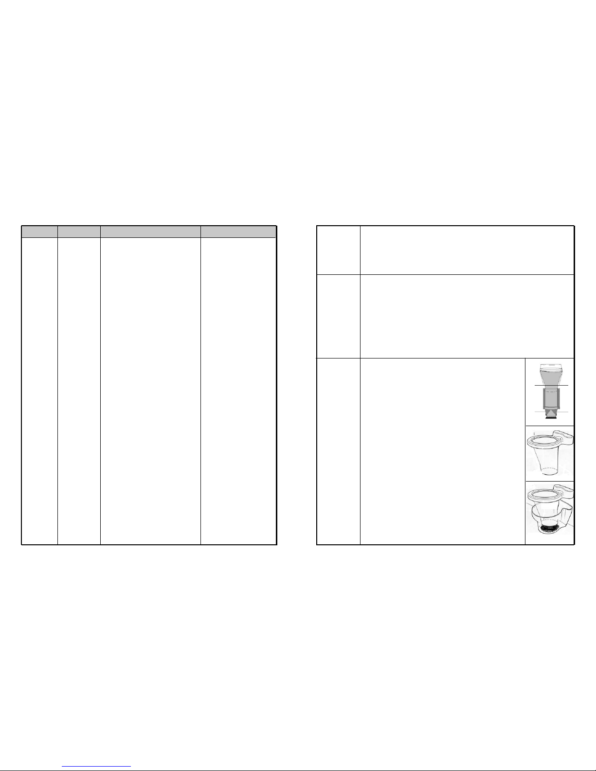
Place the toilet chute into the toilet base in the bathroom. If the toilet chute extends 1-2”(25 - 50mm)
into the transition piece, then no extension pipe pieces will be required. If the transition piece does not
extend far enough up to meet the toilet chute, then one or more extension pipe pieces will be needed.
These minimum 44”(112cm) pipe sections can be cut down to the correct length, so that when assembled and placed in the transition piece, they extend 1-2”(25-50mm) into the toilet chute. After taking
into account the overlap, each pipe piece provides an extension of about 41”(104cm).
A pipe section, which comes in two halves, can be cut to the correct length, by cutting the required
amount off the str aight ends of each half with a hac k saw.
It is easier to cut pipe sections to length before joining the two halves together. After cutting, clean up
the edges with a sanding block and coarse (40-60 grit) sandpaper.
Before joining the two halves of the pipe pieces, spread a bead of silicone caulking from top to bottom
along the inside of both halves of pipe pieces (so that the inside of the pipe section will be sealed).
Press the two halves together, and secure them by screwing the self tapping screws provided into the
pre-drilled holes. Run a finger or spatula up along each joint inside the chute to remove any excess silicone. Ensure that when the pipe pieces are assembled together, and the bottom piece is placed in the
transition piece of the composting unit, so that the top of the tr ansition piece extends 25-50mm over the
chute or extension pipe piece.
Pre Assembly Check:
Before finishing the installation, make sure everything fits
together properly. T he top of the pipe piece is belled out to accommodate the
toilet chute. Place the transition piece in the cut out provided on the top of the
composting unit. Place the pipe pieces, if any, inside the transition piece. Next
lower the toilet top onto the base so that the chute projects 1-2”(25-50mm) into
the pipe piece or directly into the transition piece if no pipe piece is used.
Ensure that the toilet top is properly located over the toilet base, that the chute
is completely vertical, and that the screws to attach the top to the toilet base, line
up properly. ( Fig. A) If the pre-assembly check appears OK, then disassemble
and reassemble each piece as in the pre-assembly check(see above).
To assemble the toilet top with the chute, line up top with the chute and fasten
the four screws around toilet opening and cover with the snap caps (Fig B).
Insert the toilet chute into the toilet base until the toilet top rests on the base
(Fig C). When reassembling use silicone caulking at the joints where the toilet
chute sits inside the extension pipe piece, where the extension pipe piece sits
inside the transition piece and where the transition piece sits inside the composing unit. Use a finger or spatula to remove any excess silicone.
Next, line up the two pre-drilled holes which go through the front of the toilet top,
through into the toilet base, and insert the two scre ws without tightening them.
With these front two holes secured, tilt the rear of the top down over the base
until the last four screws are located. Screw in all six scr ews, making sure not to
over-tighten, and push on the plastic caps over the screw heads. Attach the toilet seat by threading the nylon screws through the toilet seat hinge and into the
holes into the toilet top. Put the black removable bowl liner into place under the
toilet seat.
Determining
if an
Extension
Pipe Piece is
Needed
Assembling
and Installing
the Extension
Pipe Pieces
(If Needed)
Finishing the
AF “Dry
Toilet”
Installation
Fig. A
Fig. B
Fig. C
Page 14
- 13 - - 22 -
Symptom Cause Remedial Action Prevention
Waste not
Breaking
Down at all
(cont'd’)
Lumps
If many large
lumps have
formed in drum,
you will need to
remove them or
break them up
with the rake tool.
Follow the prevention column to
ensure this does
not happen.
Drum Too
Full
Note: The drum is
too full when it is
over 1/2 full, and
the door is not
closing properly.
Antibiotics being
used for more than
a few weeks on a
continuous basis
may kill bacteria.
Compost Too Dry
Over-Rotation of
Drum
Peat moss used as
bulking material with
no wood shavings.
Compost not emp-
tied into finishing
drawer in a timely
fashion.
Kitchen/Garden
Waste added
Empty drum. Hose out inside of drum. Restart
compost according to “Initial System Startups”.
Follow instructions for “Compost Too Dry” above.
And also add 1-2 QUARTS(2 liters) of warm
water.
Follow “ONGOING TOILET MAINTENANCE”, and
also add 1-2 QUARTS(2 liters) of wood shavings.
Begin using 70% wood shavings, 30% peat
moss as bulking material.
1. Remove compost until drum is only half full or
less. Rotate compost thoroughly to aerate,
and add compost accelerant if available.
2. If you need to dump more than one drawer of
compost, and you do not already have a suitable backyard compost heap, you may try an
open-slatted wooden crate (such as the kind
used to pack age fruits and vegetables).
Layer compost with bulking material and leave
crate outside for around 2 months to finish
composting.
When used normally, antibiotics will
only slightly slow compost. Add
compost accelerant during this period to accelerate compost action.
Urinating elsewhere during this period will also help minimize the damage to the compost.
Follow recommendations for checking and adding moisture in “PERIODIC CHECKUP”.
Drum should be turned three times
a week, 6 rotations each time; once
before departure for weekend use.
Use proper bulking material.
When drum is 1/2 full, remove some
compost to the finishing drawer by
rotating the drum backwards, to
avoid surprise over-filling of drum.
Do NOT let drum get above 1/2 full.
(The drum is 1/2 full when the
level of the compost reaches 46”(100-150mm) below where the
drum door hangs) This will lead to
lack of aer ation, and anaerobic
compost, and the inconvenience of
having to remove more than one
drawer.
Do Not add kitchen or garden
waste.
The Centrex 2000 AF composting unit has a 3”(75mm) diameter air intake hole at the rear of the unit,
just above the floor of the evaporation chamber. A 3”(75mm) intake cover is supplied with the hardware kit in the composting unit. The air intake can be removed and replaced with the 3”(75mm) intake
cover if it proves necessar y to pull more air down the AF “Dry Toilet” chute. This cover should only be
inserted if it is needed, because blocking the air intake will reduce the airflow over the evaporation
chamber, which in turn reduces evaporation performance.
If the air intake cover is in place (See “Adjusting the Air Intake Covers”
above), but the toilet is more than one extension pipe piece above the composting unit so the fan is unable to draw air down through the toilet chute,
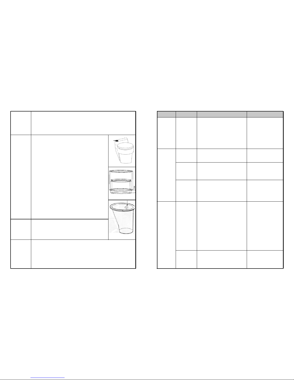
then it is necessary to vent the toilet directly. The toilet itself should be
vented as follows:
i) Obtain sufficient pipe and fittings for the vent using either 3”(75mm)
sewer pipe or plumbing pipe.
ii) Trace the outside outline of the pipe on the circular section at the top
and rear of the toilet top at either the left or right of the toilet top
depending on which side it is more convenient to vent from.
(See Fig. A)
iii) Cut out the hole by first drilling a hole in the circumference of the traced
outline, and then carefully using a jig saw to complete the circle. Sand
to enlarge or smooth off the edges if necessar y.
iv) Cut a short length of pipe and glue it into a connector, with 1/2” (13mm)
of pipe protruding from the connector. Place this protruding end in the
newly cut hole to locate the base of the vent stack. (Fig. B)
v) Erect the vent stack as vertically as possible following the same rules as
outlined on page 14, in the vent pipe location section.
vi) If it is not possible to make this vent ver tical or close to vertical, a 12
Volt fan may also have to be installed in this vent stack. Since the 12
Volt fan comes in a 12”(300mm) length of 4”(100mm) sewer pipe,
transition coupling will be needed if 3”(75mm) pipe has been used.
Remove the bowl liner in the toilet top, and drill out a large number (15-20)
holes 1/4”(6mm) or bigger at the top rear of the chute piece no more than
3”(75mm) down from the top edge. (See Fig. C)
These holes will enable the vent on the top of the toilet to dr aw air up the
chute.
The 1”(25mm) Safety drains at the left of the “Centrex 2000 AF Family”, exit to both the front and
back. To connect one of the drains, (whichever is convenient), remove the plug, attach the 1”(25mm)
hose (included) and secure with a hose clamp. Ensure there are no kinks or upward bends in the dr ain
hose.
Adjusting the
Air Intake
Installing the
Optional
Vent on the
AF “Dry
Toilet:”
Cutting Holes
in the Toilet
Chute
Drain
Installation
Fig. A
Fig. B
Fig. C
Page 15
- 14 -- 21 -
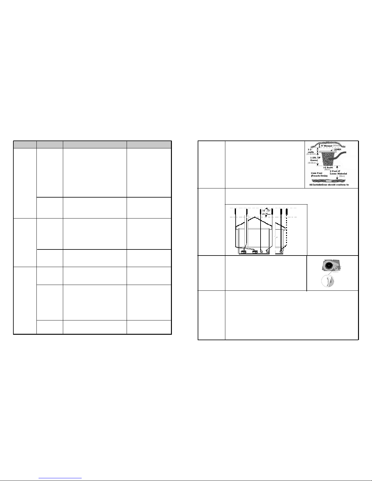
Handling
Effluent
Vent Piping
Location
Adjusting
the fan gate
(Electric and
AC/DC)
Vent
Piping
Installation
The following are possible options to take care of the liquid:
- Use a container which is emptied periodically (water jug or
small barrel). This ensures a closed loop system.
- Feed into a lined pit filled with gravel and sand. Such a
recycling bed also ensures a closed loop system.
- Feed into a small cesspit or “french drain”.
-Plumb into an existing septic or holding tank line.
Installation should be in accordance with applicable local regulations.
Piping can be installed up the inside wall; through the wall at a slight angle and up the outside wall. The
choice depends on ease of installation, visibility, and (especially if the toilet is to be used consistently
through a cold winter), the necessity of insulating all exposed vent pipe.
The vent on the right is a 4”(100mm)
on-electric vent.
All others show possible 2”(50mm)
Centrex 2000 (electric) vent configurations.
If you believe that there may be a downdraft outside of the
building, it may be a good idea to remove your fan assembly
prior to installation and set the fan gate to ‘0’ to prevent urine
odour in the bathroom. The fan gate is factor y set to ‘3’, which
recirculates air within the unit. If there is a downdraft you may
get blow back into the room where the unit is installed. When
setting the fan gate to ‘0’, you may lose some evaporation so it
is also wise to hook up the emergency drain.
Piping and fittings are of standard 2”(50mm) PVC thin wall tubing(central vacuum) and/or 4”(100mm)
PVC thin wall pipe. Additional pipe or fittings can be purchased from a building supply dealer. If you cannot find them near your location, you can substitute schedule 40 pipe and use a rubber coupling to join
this pipe to the unit.
i) Minimize the number of shar p angles in the 2”(50mm) vent as each reduces vent efficiency. The
4”(100mm) vent should be installed as near to vertical as possible. If it is necessary to have
angles in the 4”(100mm) vent pipe 45 degree angles are used whenever possible. On the 4”
(100mm) DC stack, bends should be limited to 2 - 45 degree angles. This will necessitate the
installation of a 12 volt fan.
ii) Do not lead the 2”(50mm) vent pipe downward or horizontally at any point. This may lead to the
Symptom Cause Remedial Action Prevention
Compost
Too Wet
Your compost
is too wet when
there are
standing pools
of liquid.
Compost will
smell of sewage
and is
anaerobic
Compost
Too Dry
Compost is too
dry when compost looks flat
and brown rather
than rich and
black.
Waste not
Breaking
Down at all
If this is the case,
the drum will fill
up quickly
Compost porosity is
poor. Too much
peat moss has been
used as a bulking
material. This is
compacting, preventing liquid from
draining through,
and leaving no free
air space for oxygen.
Drum screen
clogged
Moisture not being
added periodically
or before departure
on cottage units.
Toilet not used for
urination .
Insufficient bulking
material or not
enough peat moss.
Insufficient Microbes
Temperature around
unit under 15C
Bleach or other
anti-bacterial chemicals added.
For an immediate improvement in porosity add
about 2 liters of wood shavings, of any kind
(except cedar, cypress, juniper, bamboo, teak,
redwood, eucalyptus, sugar cane, or any other
woods with anti-bacterial properties) to the dr um.
On an ongoing basis, change bulking material a
mixture of 60% wood shavings and 40% peat
moss mix.
Remove the finishing drawer. Scrub screen
(which will be visible with a flashlight on the bottom of the dr um) with wire brush. The overflow
drain should be hooked up.
Add 2 to 4 litres of warm water to compost in
order to bring it up to appropriate moisture level.
Peat moss retains moisture. 40-60% moisture
content is ideal for aerobic microbes to thrive.
Add compost accelerant or unsterilized black
earth from a garden center.
Install heat source to increase temperature.
Temperature should be kept above 13 -15C constantly if toilet will be used on an ongoing basis.
Empty drum. Hose out inside of drum. Restart
compost according to “Initial System Startups”.
Use 40% peat moss, 60% wood
shavings as a bulking material.
Follow section on moisture in
“PERIODIC CHECKUP”.
Use toilet for urination.
Add correct bulking material.
Be sure to add compost accelerant at startups.
Install unit in warm area. The
warmer the area, the better your
compost will be! If evening temperatures fall below the prescribed
temperatures on a residential unit,
consider installing a heat source
on a timer for evenings.
Never add bleach or cleaning
chemicals.
Page 16
- 15 -
- 20 -
This chapter will deal with problem that may arise with your compost, what is required to make your compost healthy
and how to correct problems if they arise.
Aerobic Compost Requirements
In a Sun-Mar, a good compost is predominantly aerobic, which
means that oxygen is available for aerobic bacteria throughout
the Bio-drum. Aerobic bacteria consume waste quickly and
odourlessly to produce carbon dioxide and water vapor and
leave behind a small fraction of the original waste volume in
the form of basic minerals. The end compost is a mix of valuable minerals and bulking material that has not decomposed.
To work effectively to break down waste, aerobic bacteria need
oxygen, moisture, available carbon (from the bulking material),
and warmth.
In a Sun-Mar, oxygen is provided by the tumbling of the dr um
and the bulking material leaving free air space within the compost. Moistur e is provided by the waste, and is made available
to aerobic bacteria by the moisture retention proper ties of the
bulking material. If the compost is too dr y, add warm water.
In summary, to keep the compost aerobic, it is important to
rotate the drum, add bulking material, and keep the compost
moist.
Oxygen
Lack of oxygen becomes a problem where:
- Too much moisture eliminates the free air space,
- A lack of bulking material limits free air space,
- Aerobic bacteria use up oxygen in the compost.
Lack of oxygen causes the compost to become increasingly
anaerobic, which means that aerobic bacteria are displaced by
anaerobic bacteria. Anaerobic bacteria work slowly and produce undesirable ammonia, hydrogen sulphide, and methane.
Consequently, the maintenance of ‘free air’ space by periodically rotating the drum and adding the right bulking material is
very important in Sun-Mar units. Excessive rotation is not
helpful and can harm the compost by disturbing the bacteria
too much.
Moisture
If there is too muc h moisture, and the compost is approaching
saturation, oxygen is pushed out and anaerobic activity predominates. On the other hand, if there is too little moisture,
aerobic activity slows. For this reason, it is important to maintain adequate moisture levels (40-60% moisture content is
ideal). Generally, if you shine a flashlight in after mixing, there
should be a slight sheen of moisture on your compost.
Warmth
Too little warmth will cause aerobic activity to slow. Below 1355F(15C) degrees, microbes will go dormant and composting
will stop. Composting speeds increase dramatically with temperature.
Characteristics of a Bad Compost
If your compost is over 8 weeks old and it exhibits one or more
of the following characteristics , then an operating change is
indicated.
Extraction required too often (under 4
weeks)
Large Lumps present in compost
Compost muddy or clay-like
Flies present (this may also be a problem
with foreign matter being added to unit; see
section on flies)
Compost has strong unpleasant smell of
sewage when drum is tur ned.
Toilet paper present in finishing drawer
Troubleshooting
In using this troubleshooting section, you should follow remedial actions in the order that they are given, unless you are
sure of the problem. You should see improvement in a week,
and your compost should be back to normal in 2-3 weeks. If
it is not, make sure that “Ongoing Toilet Maintenance” is being
followed and check the mechanical troubleshooting section.
vent pipe being blocked by condensation which would cause a urine smell in your bathroom.
iii) All connectors in the vent pipe should be sealed.
Use silicone for the connection of the vent stack to
the toilet in case the composting unit has to be moved or you have to access the fan
. PVC cement
may be used in the rest of the stack installation if desir ed.
iv) All exposed 2”(50mm) vent pipe should be insulated with the foam insulation. This is especially
important for winter or residential use to prevent condensation.
v) The Sun-Mar 12 Volt fan is fitted inside a 12”(300mm) length of 4”(100mm) vent pipe for easy
installation, should it be needed. It is installed by either cutting out a section of the vent immediately
above the composting unit, or by raising the vent stack off of the composting unit and inserting the
fan section. The fan can be used with a solar panel and 12 volt battery, or by purchasing a 12 volt
adapter from your local hardware store and simply plugging it into the wall.
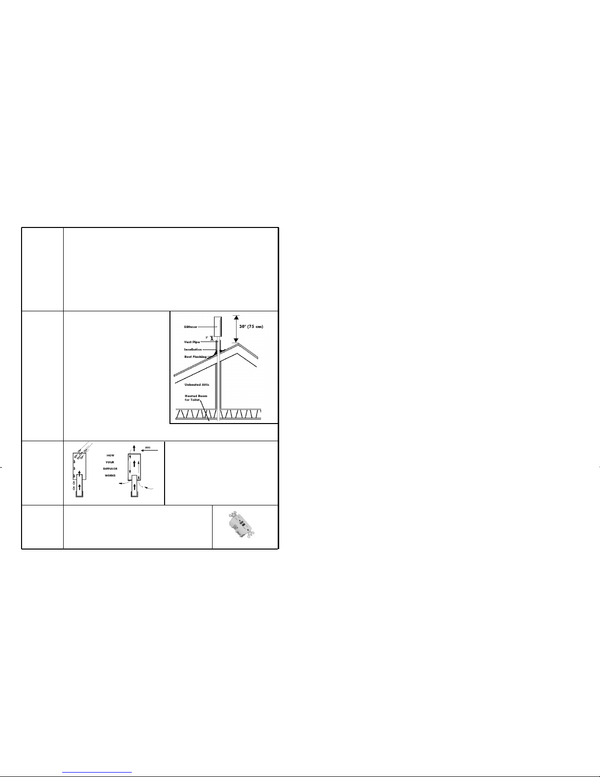
As shown in the installation, the vent stack should
end about 20-30”(60-90mm) above the peak of
the roof so that it is less subject to downdr aft.
Where the piping is taken through the roof, the roof
flashing provided should be used to seal the installation. Inser t the vent into the bell of the roof flashing and slide the roof flashing down until it lays
evenly on the roof. Slip the upper edge or the roof
flashing flange under the shingles. Outline the
flashing on the roof. Raise the roof flashing and
apply silicone sealant or roofing tar inside the outline. Slide the flashing back into place and firmly
press onto the sealant. The flashing is properly
placed when the top part of the roof flashing flange
is tucked under the shingles and the lower portion
is sealed on top of the shingles so that water sheds
easily. Secure the flashing with corrosion resistant nails at each cor ner and along sides. Any exposed nails
should be sealed with silicone caulking.
The diffusor provided with the unit is a simple device to
be installed at the top of the vent stack with the larger
pipe protruding above the smaller. To install, simply
glue the diffusor on the topmost section of vent pipe.
The diffusor design encourages updraft, and discourages wind and weather from going down the vent stack.
Unlike wind turbines, diffusors are less likely to freeze
up in winter, and are more effective in calm weather.
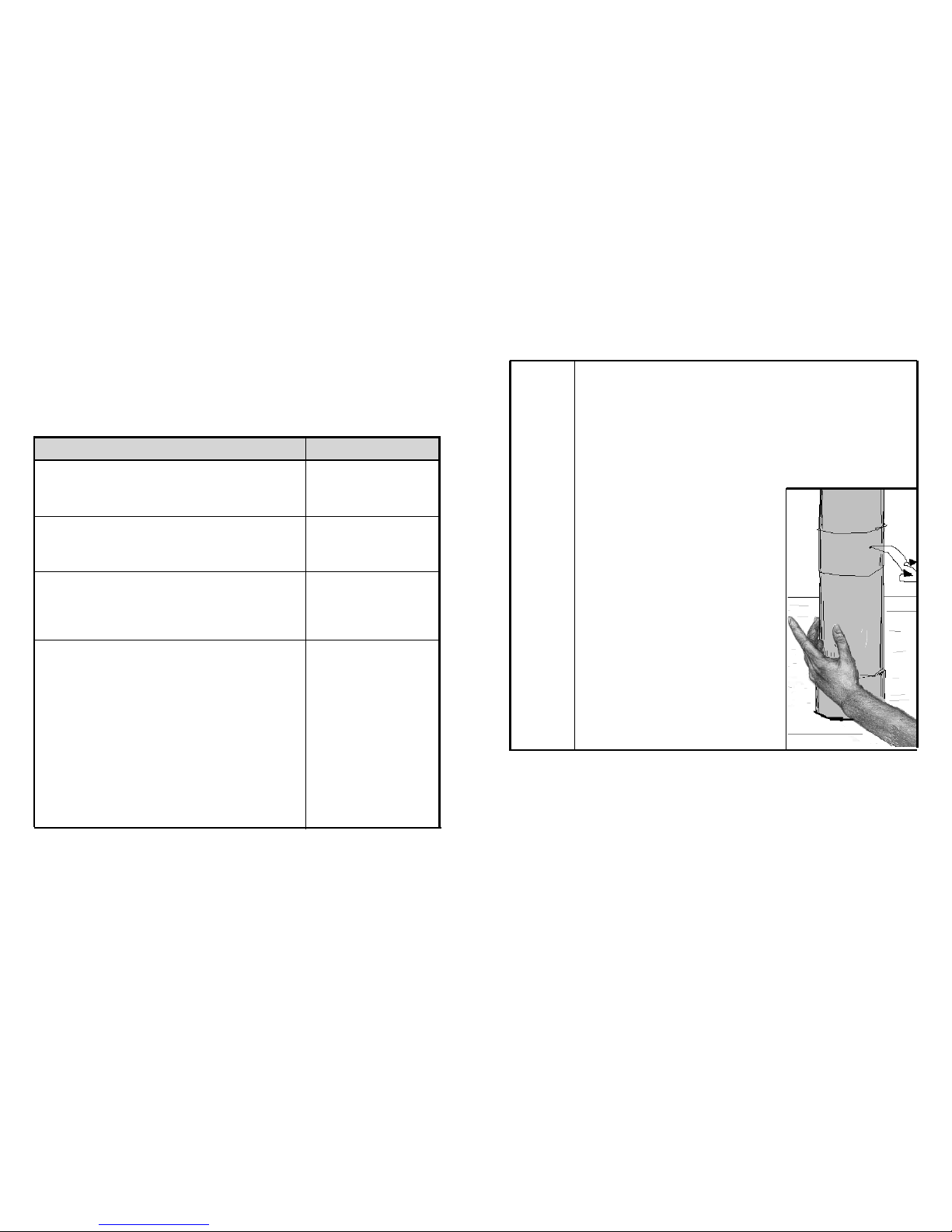
A ground fault circuit interrupter (GFI) is recommended to protect your
composting unit from electrical problems.
This may be installed directly on the wall socket or at the circuit breaker.
An example is shown in the picture at the right.
Vent
Piping
Installation
(Cont’d)
Leading the
vent
through the
roof
The Diffusor
Electrical
Considerations
(Electric and
AC/DC)
Chapter 4
Compost Troubleshooting
Page 17
- 19 - - 16 -
Ongoing Toilet Maintenance
The procedure below is designed to keep the compost:
- Moist, but not too wet
- Well aerated and mixed
- Well balanced and aerobic
Add 1 cup(250ml) or 2 handfuls of a mixture of 40% peat moss and 60% non-
antibacterial wood shavings to the Bio-Drum per person per day of use.
Turn Handle to rotate the drum a minimum of 6 complete revolutions ever y
second day when in use. Pull the drum locker button and turn the dr um 1/2 turn
past its’ resting position to level the compost inside the drum. To prevent a mess,
DO NOT forget to return the drum opening to a position under the waste pipe.
Unplug the unit if you are leaving for a period of mor e than a few days. If you
are leaving one weekend and coming back the next, you may unplug the unit. If
you are leaving for a period of more than a few days, or the compost appears dry,
add approximately 1quart(2 liters) of warm water to keep the compost moist.
Remove compost into the finishing drawer when the drum is 1/2 full. It is 1/2
full when the compost reaches a level about 100-150mm below the bottom of the
drum door when the door is open.
To empty some compost into the drawer,
pullthe drum locker button
and rotate the
handle counter-clockwise (to turn the drum cloc kwise). Turn at the same speed you
would normally do for mixing. This will fill the finishing drawer. Compost in the
drawer should then sit in the drawer, in the unit to finish composting for at least 2
months before the drawer is emptied. If necessary, use the rake to level the compost in the drawer. If there is not enough compost in the drawer, turn the drum
backwards (clockwise) again1 rotation.
We recommend storing compost in a container before using.
If your unit is used seasonally and is not used heavily,
you may not have to remove any compost at all during
the season. If so, follow “Annual Startups”.
- Maintains the carbon/nitrogen
balance
- Absorbs liquid
- Helps oxygen penetrate for aerobic
composting
- Mixes and oxygenates the compost
- unplugging unit will conserve power
and keep compost from drying.
- addition of water helps keep the
compost moist
- Moves some compost to the next
stage for finishing
- Ensures that the drum does not get
too full
- Provides extra time for composting
to be completed
Every Sun-Mar AC/DC and NE model comes with a 12 Volt Fan for installation in the 100mm stack. Its
installation is required in the following situations:
-If you are installing both 2”(50mm) and 4”(100mm) vent stacks (pr events downdraft from
the 2” or 50mm vent)
-If you are in an area where you are subject to downdraft
-If you are using the unit residentially
-If you need to install the vent stack with bends
We include it because many AC/DC owners do install both vent stacks. It may also be installed later if you
wish simply by cutting a section out of your vent and replacing it with the fan.
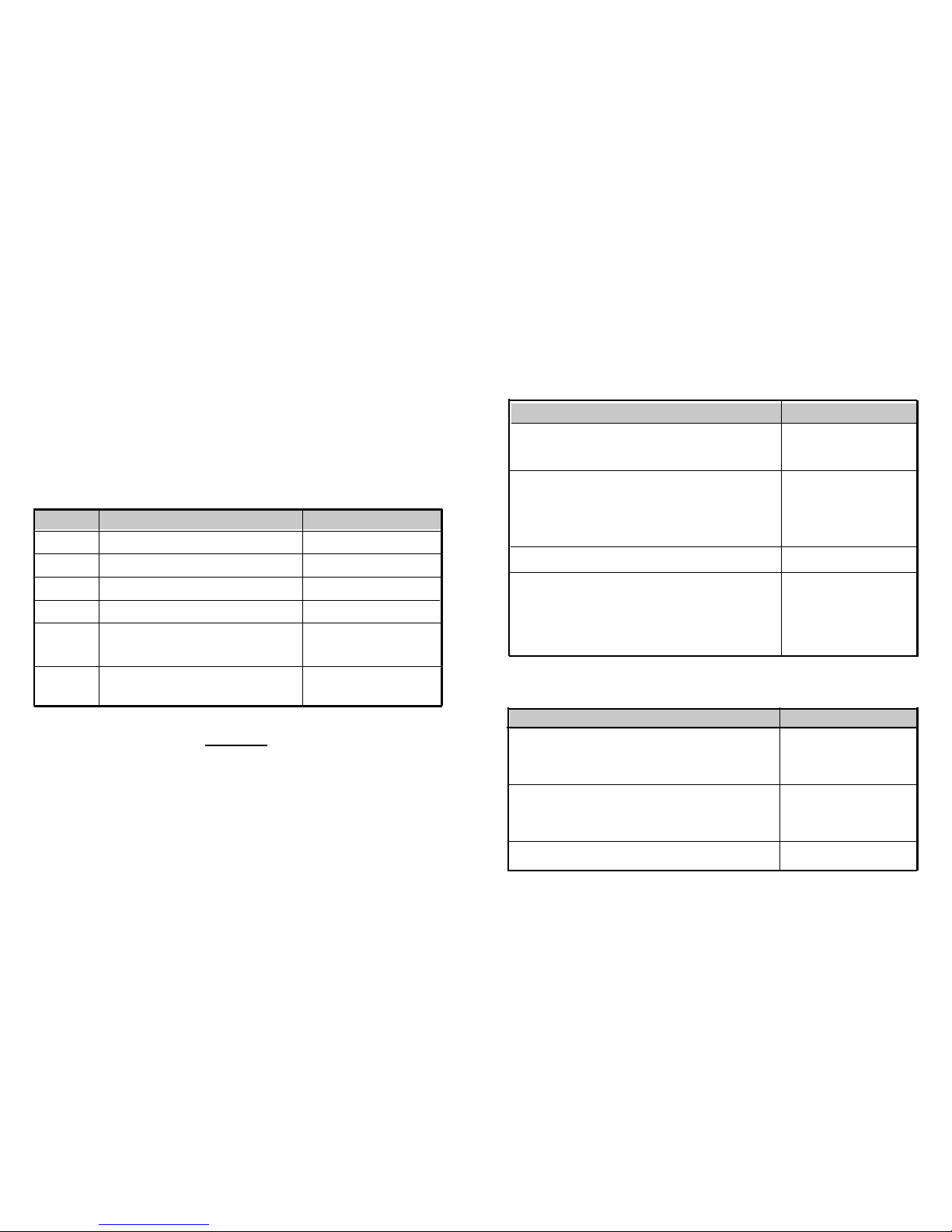
To install the fan initially, pick a spot on the stack that you can
reach easily. In order to get the best evaporative performance
from the fan, install it near the composting unit if possible
(remember, the fan will still not be enough to evaporate all liquids in a non-electric or DC only environment). Once you have
placed it where you wish, use silicone caulking, or rubberized
couplings, to make the installation airtight. Do not use glue as
you may need to change the fan at a later date.
The 12 Volt Fan may be powered with a battery that is connected
to a generator, solar panel, or other alternative energy system.
For use in AC, purchase a 12 Volt to AC Adapter from any electrical store and snip off the female end - wire the positive wire to
the red wire on the fan, and the negative wire to the blue wire on
the fan. Tie them off with small wire connectors, and plug your
AC Adapter into the wall.
The 12 Volt Fan should be continuously running if used, as if it is
not running it will act as a block in the vent stack.
12 Volt Fan
Installation
(AC/DC and
NE)
Action Reason for Action
Page 18
- 17 - - 18 -
Annual Start Up (seasonal units only)
Many units are only used regularly throughout the summer. For such seasonal units Sun-Mar recommends that the
following start up procedure be followed at the beginning of the season.
Action Reason for Action
Empty the compost that had been left in the finishing drawer, and use the rake
to clean out the evaporation chamber.
Remove additional drawers of compost (if there is more than 6-8” or 150200mm in the drum), by releasing the drum lock (white button on right side of
unit), and rotating the drum clockwise (the handle tur ns counter-clockwise) to
extract compost into the drawer. (At the beginning of the season, it will all be finished compost) Empty the drawer and repeat extraction cycle until the level in the
drum is reduced to about 6”(150mm).
Add 1 gallon(4 liters) of war m water.
As an option for optimal composting,
Add composting accelerant. We do not recommend using topsoil as it may contain
fly larvae.
-
Your fertilizer is ready.
- This is a good time to remove peat
debris
-
Frees space in the composting
chamber for the new seasons composting.
- Raises moisture level
- Even though the compost still has
microbes in it, you may want to start
the year by replenishing your batch
of microbes.
Chapter 3
Start Up and Use
Initial System Start Up
Begin operation by carrying out the star t up procedure described below, and then continue with the “Ongoing
Toilet Maintenance” routine. It normally takes six weeks before a compost is properly established. You will know
this has happened when:
- Compost Volume increases more slowly
- Compost turns black and becomes loam-like
- Toilet paper decomposes within a few days
Action Why?
-Provides carbon base and initial mass
for compost.
-Adds necessary microbes which will
breakdown the compost.
-Moistens carbon base
-The unit is ready for use
-Until the compost is active, some peat
moss may fall through the screen or
drum door into the evaporating chamber
Extends the surface area of evaporation
chamber
8 gallons(30 liters) of bulking mixture (60% shavings and
40% peat moss) to the drum.
Compost accelerant
About 1gallon(4 liters) of warm water into the drum
Fan and heater are operating
Loose peat moss from the evaporating chamber until the
compost is established, which takes approximately 6 weeks.
Black evaporating tray under dr um screen to the left of the
drawer.
Periodic Check Up
Once your unit has been through initial or annual start-ups, and ongoing maintenance procedures are being followed,
Sun-Mar recommends a system of periodic checks be under taken.
Action Reason for Action
Rake solid debris from the evapor ation chamber, making sure to rake from the
rear of the chamber, including the back two corners nearest to the drains of the
unit. Raking should occur on a twice yearly basis for cottages (best done at annual
startups and half way through the season), and a bi-monthly period for continuous
users.
Check your compost moisture level on each visit for cottage users and once
every two weeks for continuous users. This can be done by shining a light into the
Bio-Drum. The compost should have a slight gloss or shine to it. A moisture meter
may also be used if so desired. Range should be 4-6, which represents 40% to
60%
Pour 1 gallon(4 liters) of warm water down the toilet.
- Ensures drains cannot get plugged and
evaporation is improved.
- A good compost is between 40% and
60% moisture content.
- Prevents lumps, ensures toilet paper
breaks down quickly.
- Prevents insects
- Ensures waste piping remains freeflowing.
CAUTION
1. Do
NNOOTT
add or clean the toilet bowl with chemicals. Chemicals will kill the bacteria.
IINNSSTTEEAADD
, clean the bowl hot water and baking soda or a weak vinegar and water solution.
2. Do
NNOOTT
add plastic, glass, metal, cleaning fluids, cigarettes. Add only waste and bulking material.
3. Kitchen or garden waste are
NNOOTT
recommended.
*
Toilet paper is a good source of carbon and should be added after use.
ADD
ADD
SPRINKLE
PLUG IN
RAKE
POSITION
Although the start up instructions remain the same no matter what your application, different situations
will require different actions and this chapter will explain what they are.
 Loading...