

Sunlover Oasis Inverter Series, Oasis I9, Oasis I12, Oasis I17, Oasis I19 Installation Instructions Manual
Head Office
62 Parkhurst Drive
Knoxfield VIC 3180
T: 03 9887 2131
New South Wales
Unit 1, 20-22 Foundry Road
Seven Hills NSW 2147
T: 02 9838 0000
Queensland
Unit 1, 8 Reichert Drive
Molendinar QLD 4214
T: 07 5679 6821
sales@sunloverheating.com.au
sunloverheating.com.au
SWIMMING POOL HEAT PUMP UNIT
Installation & Instruction Manual
Inverter Series
I9 | I12 | I17 | I19

CONTENTS
1. PREFACE ......................................................................................................................................................... 3
2. SPECIFICATION ............................................................................................................................................. 5
2.1 Performance data of Swimming Pool Heat Pump Unit................................................................................. 5
2.2 The dimensions for Swimming Pool Heat Pump Unit ................................................................................... 6
3. INSTALLATION AND CONNECTION ......................................................................................................... 7
3.1 Installation illustration .................................................................................................................................. 7
3.2 Swimming Pool Heat Pumps Location .......................................................................................................... 8
3.3 How Close to Your Pool? ............................................................................................................................... 8
3.4 Swimming Pool Heat Pumps Plumbing ......................................................................................................... 9
3.5 Swimming Pool Heat Pumps Electrical Wiring ............................................................................................ 10
3.6 Initial start-up of the Unit ........................................................................................................................... 10
4. USAGE AND OPERATION ......................................................................................................................... 11
4.1 Interface display .......................................................................................................................................... 11
4.2 Key and icon function instruction ............................................................................................................... 11
4.2.A - Key function instruction ..................................................................................................................... 11
4.2.B - Icon function instruction .................................................................................................................... 12
4.3 Startup & shutdown .................................................................................................................................... 13
4.4 Mode switch ................................................................................................................................................ 14
4.5 Temperature setting ................................................................................................................................... 15
4.6 Clock setting ................................................................................................................................................ 15
4.6.A System time setting ............................................................................................................................. 15
4.6.B Setting and cancelling the Timer ON/OFF function ............................................................................. 16
4.7 Silent setting ............................................................................................................................................... 17
4.7.A One-click silent function ....................................................................................................................... 17
4.7.B Setting and cancelling the silent function ............................................................................................ 18
4.8 Keyboard lock .............................................................................................................................................. 19
4.9 Fault interface ............................................................................................................................................. 19
4.10 Parameter list and breakdown table ........................................................................................................ 20
4.10.A Electronic control fault table ............................................................................................................. 20
4.10.B Parameter table ................................................................................................................................ 22
4.11 Main board (Oasis I9/I12) ......................................................................................................................... 22
4.12 Main board (Oasis I7/I19) ......................................................................................................................... 23
5. MAINTENANCE AND INSPECTION ......................................................................................................... 25
5.1 Maintenance ............................................................................................................................................... 25
5.2 Trouble Shooting Guide .............................................................................................................................. 30
6. APPENDIX ...................................................................................................................................................... 31
6.1 Caution & Warning ...................................................................................................................................... 31
6.2 Cable specification ...................................................................................................................................... 32
6.3 Comparison table of refrigerant saturation temperature .......................................................................... 33
6.4 Explosive view of the I 9 unit ...................................................................................................................... 34
6.5 Explosive view of the I 12 unit .................................................................................................................... 36
6.6 Explosive view of the I 17 unit .................................................................................................................... 38
6.7 Explosive view of the I 19 unit .................................................................................................................... 40

INSTALLATION & INSTRUCTION MANUAL - INVERTER SERIES – I9, I12, I17, I19 - SWIMMING POOL HEAT PUMP UNIT
sales@sunloverheating.com.au
sunloverheating.com.au
3
1. PREFACE
In order to provide our customers with quality, reliability and versatility, this product has been made to strict
production standards. This manual includes all the necessary information about installation, debugging,
discharging and maintenance. Please read this manual carefully before you open or maintain the unit. The
manufacture of this product will not be held responsible if someone is injured or the unit is damaged, as a
result of improper installation, debugging, or unnecessary maintenance. It is vital that the instructions within
this manual are adhered to at all times. The unit must be installed by qualified personnel.
The unit can only be repaired by qualified installer centre , personnel or an authorised dealer.
Maintenance and operation must be carried out according to the recommended time and frequency, as stated
in this manual.
The appliance shall be installed in accordance with national wiring regulations.
Use genuine standard spare parts only.
Do not use means to accelerate the defrosting process or to clean, other than those recommended by the
manufacturer
FAILURE TO COMPLY WITH THESE RECOMMENDATIONS WILL INVALIDATE THE WARRANTY.
Swimming Pool Heat Pump Unit heats the swimming pool water and keeps the temperature constant. For split
type unit, the indoor unit can be Discretely hidden or semi-hidden to suit a luxury house.
Our heat pump has following characteristics:
1 Durable
The heat exchanger is made of PVC & Copper Nickle tube which can withstand prolonged exposure to
swimming pool water.
2 Installation flexibility
The unit can be installed outdoors or indoors.
3 Quiet operation
The unit comprises an efficient rotary/ scroll compressor and a low-noise fan motor, which guarantees its
quiet operation.
4 Advanced controlling
The unit includes micro-computer controlling, allowing all operation parameters to be set. Operation status
can be displayed on the LCD wire controller. Remote controller can be chosen as future option.

INSTALLATION & INSTRUCTION MANUAL - INVERTER SERIES – I9, I12, I17, I19 - SWIMMING POOL HEAT PUMP UNIT
sales@sunloverheating.com.au
sunloverheating.com.au
4
1. PREFACE
WARNING
• The appliance shall be stored in a room without continuously operating ignition sources (for example
open flames, an Operating gas appliance or an operating electric heater.) If any leakage of the gas ,
fire can be occur.
• Do not pierce or burn.
• Be aware that refrigerants may not contain an odour, Appliance shall be
installed, operated and stored in a room with a floor area larger than 30 ㎡.
• Make sure that there is circuit breaker for the unit, lack of circuit breaker can
lead to electrical shock or fire.
• The heat pump located inside the unit is equipped with an over-load protection
system. It does not allow for the unit to start for at least 3 minutes from a previous stoppage.
• Caution: Single wall heat exchanger, not suitable for potable water connection.
Directive 2002/96/EC (WEEE)
The symbol depicting a crossed-out waste bin that is underneath the appliance indicates that this product, at
the end of its useful life, must be handled separately from domestic waste, must be taken to a recycling centre
for electric and electronic devices or handed back to the dealer when purchasing an equivalent appliance.
Directive 2002/95/EC (RoHs)
This product is compliant with directive 2002/95/EC (RoHs) concerning restrictions for the use of harmful
substances in electric and electronic devices.

INSTALLATION & INSTRUCTION MANUAL - INVERTER SERIES – I9, I12, I17, I19 - SWIMMING POOL HEAT PUMP UNIT
sales@sunloverheating.com.au
sunloverheating.com.au
5
2. SPECIFICATION
2.1 Performance data of Swimming Pool Heat Pump Unit
*** REFRIGERANT: R32
Model
Oasis
I9
Oasis
I12
Oasis
I17
Oasis
I19
Performance Condition: Air 27°C / Water 26°C
Heating Capacity
kW
2.2 ~ 9
2.9 ~ 12
3.8 ~ 17
4.6 ~ 19.5
Running Current
A
0.8 ~ 7
1.1 ~ 9.4
1.5 ~ 13.3
1.8 ~ 17.2
Performance Condition: Air 19°C / Water 26°C
Heating Capacity
kW
2.0 ~ 8.6
2.47 ~ 10.6
3.2 ~ 13.6
4.2 ~ 16.9
Heating Power Input
kW
1.2 ~ 7
1.5 ~ 9.2
2.2 ~ 12.8
2.6 ~ 16.8
Heating Power Input
kW
0.16 – 1.3
0.21–2.12
0.37–3.94
0.3–3.02
Cooling Capacity
kW
3.7
4.5
5.1
6.1
Cooling Power Input
kW
1.5
1.9
2.0
2.2
Running Current
A
1.1 ~ 7.2
1.5 ~ 9.2
2.2 ~12.8
2.6 ~ 16.8
Power Supply
V/Ph/Hz
10 AMP
Plug
10 AMP
Plug
240/1/50
240/1/50
Compressor Quantity
1 1
1
1
Compressor
Rotary
Rotary
Rotary
Rotary
Fan Quantity
1 1 1 1
Fan Power Input
W
100
100
100
120
Fan Rotate Speed
RPM
400 – 800
400 – 800
500 – 750
500 – 900
Fan Direction
Horizontal
Horizontal
Horizontal
Horizontal
Noise 1m
dB(A)
40 – 50
42 – 52
44 – 53
45 – 56
Silence Mode 1m
dB(A)
40
42
44
45
Water Connection
Mm
40
50
50
50
Water Flow Volume
l/m
53
70
88
110
Water Pressure Drop (max)
kPa 4 4.5 5 6
Unit Shipping Dimensions
(L/W/H)
Mm
1040 X 435
X 615
1040 X 435
X 615
1120 x 510
x 880
1120 x
510
x 880
Net / Shipping Weight
kg
45 / 54
46 / 58
55 /69
77 / 95
Cooling capacity is based on 19 °C ambient air temperature and 26°C water temperature
INSTALLATION & INSTRUCTION MANUAL - INVERTER SERIES – I9, I12, I17, I19 - SWIMMING POOL HEAT PUMP UNIT
sales@sunloverheating.com.au
sunloverheating.com.au
6
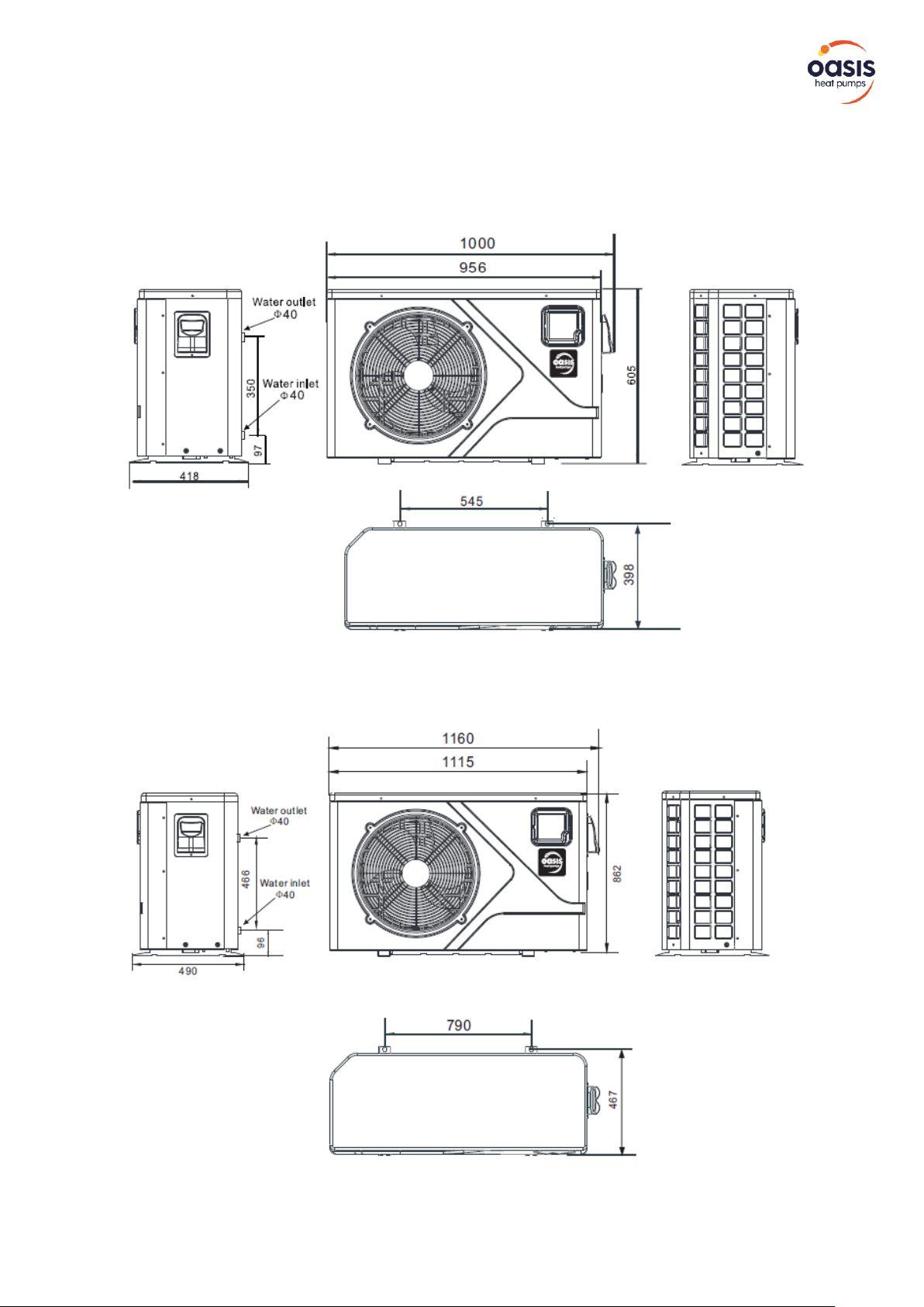
2. SPECIFICATION
2.2 The dimensions for Swimming Pool Heat Pump Unit
Oasis I9 / Oasis I12
Oasis I17 / Oasis I19
INSTALLATION & INSTRUCTION MANUAL - INVERTER SERIES – I9, I12, I17, I19 - SWIMMING POOL HEAT PUMP UNIT
sales@sunloverheating.com.au
sunloverheating.com.au
7
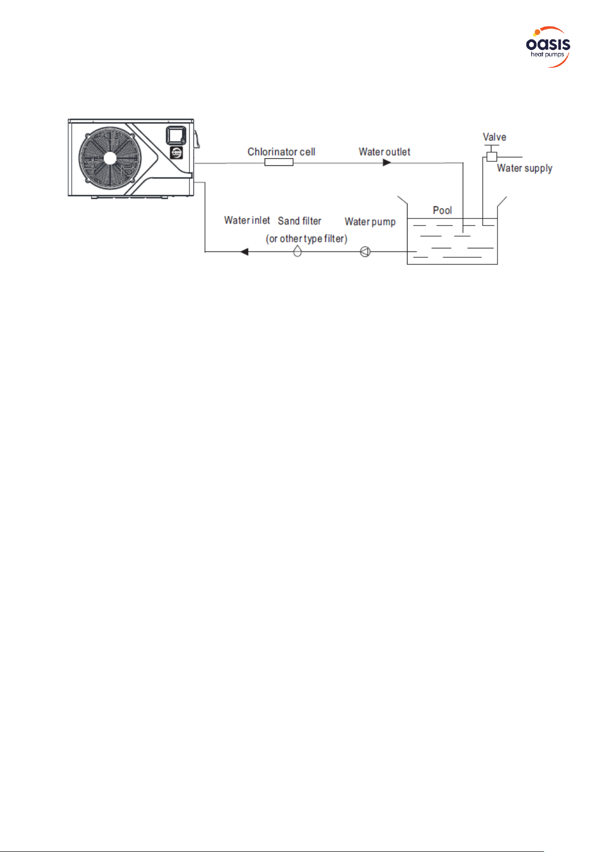
3. INSTALLATION AND CONNECTION
3.1 Installation illustration
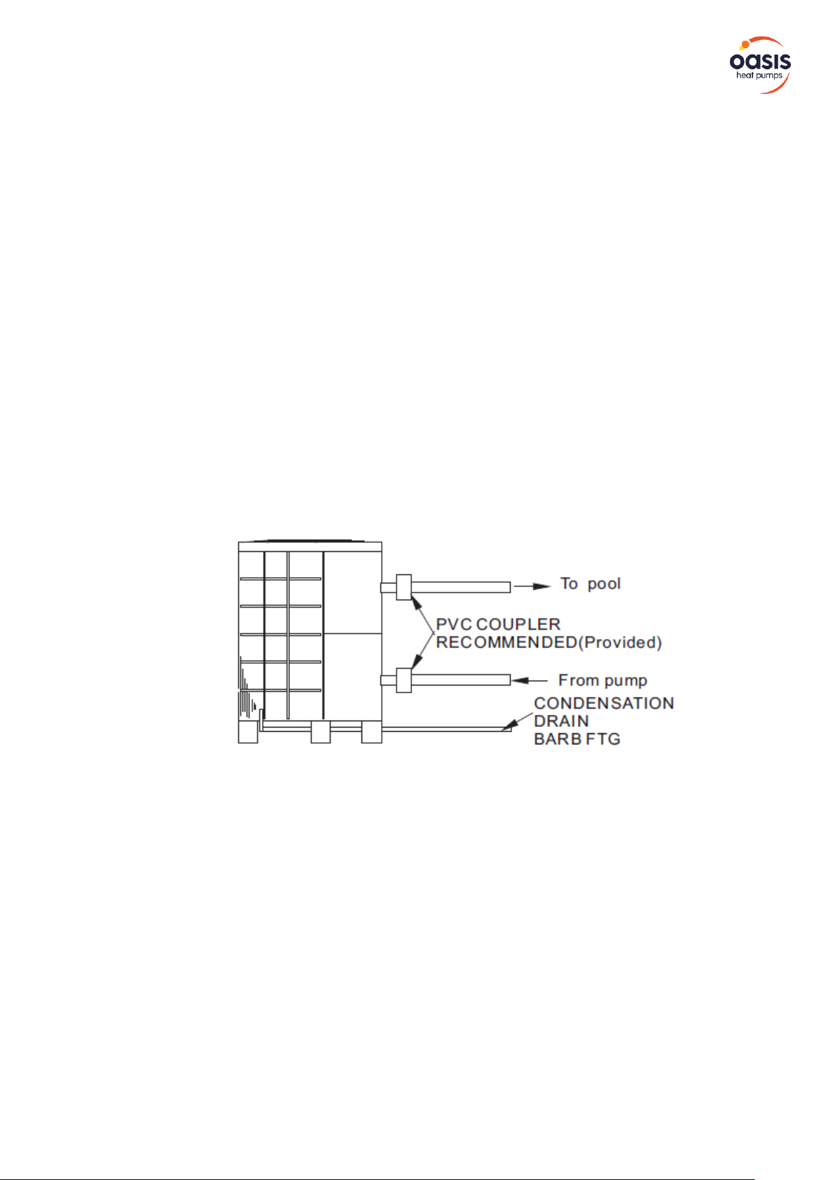
Installation items:
The factory only provides the main unit and the water unit; the other items in the illustration
are necessary spare parts for the water system, that provided by users or the installer.
Attention:
Please follow these steps when using for the first time
1. Open valve and charge water.
2. Make sure that the pump and the water-in pipe have been filled with water.
3. Close the valve and start the unit.
ATTN: It is necessary that the water-in pipe is higher than the pool surface.
The schematic diagram is for reference only.
Please check the water inlet/outlet label on the heat pump while plumbing installation.
INSTALLATION & INSTRUCTION MANUAL - INVERTER SERIES – I9, I12, I17, I19 - SWIMMING POOL HEAT PUMP UNIT
sales@sunloverheating.com.au
sunloverheating.com.au
8
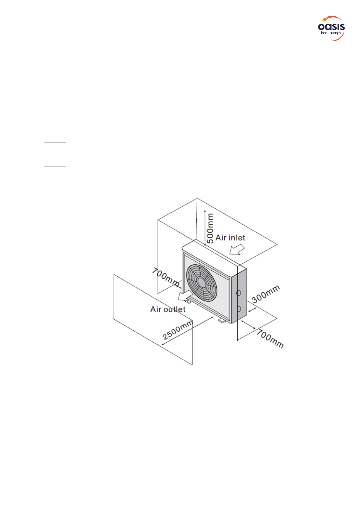
3. INSTALLATION AND CONNECTION
3.2 Swimming Pool Heat Pumps Location
The unit will perform well in any outdoor location provided that the following three factors are
presented:
1. Fresh Air 2. Electricity 3. Pool filter piping
The unit may be installed virtually anywhere outdoors. For indoor pools please consult the
supplier. Unlike a gas heater, it has no draft or pilot light problem in a windy area.
DO NOT place the unit in an enclosed area with a limited air volume, where the units
discharge air will be re-circulated.
DO NOT place the unit to shrubs which can block air inlet. These locations deny the unit of a
continuous source of fresh air which reduces it efficiency and may prevent adequate heat
delivery.
3.3 How Close to Your Pool?
Normally, the pool heat pump is installed within 7.5 metres of the pool. The longer the distance from the pool,
the greater the heat loss from the piping. For the most part, the piping is buried. Therefore, the heat loss is
minimal for runs of up to15 meters (15 meters to and from the pump = 30 meters total), unless the ground is
wet, or the water table is high. A very rough estimate of heat loss per 30 meters is 0.6 kW-hour, (2000BTU) for
every 5 ℃ difference in temperature between the pool water and the ground surrounding the pipe, which
translates to about 3% to 5% increase in run time.
INSTALLATION & INSTRUCTION MANUAL - INVERTER SERIES – I9, I12, I17, I19 - SWIMMING POOL HEAT PUMP UNIT
sales@sunloverheating.com.au
sunloverheating.com.au
9
3. INSTALLATION AND CONNECTION
3.4 Swimming Pool Heat Pumps Plumbing
The Swimming Pool Heat Pumps exclusive rated flow titanium heat exchanger requires no special plumbing
arrangements except bypass (please set the flow rate according to the nameplate). The water pressure drop is
less than 10kPa at max. Flow rate. Since there is no residual heat or flame Temperatures, the unit does not
need copper heat sink piping. PVC pipe can be run straight into the unit.
Location: Connect the unit in the pool pump discharge (return) line downstream of all filter and pool pumps,
and upstream of any chlorinators, ozonators or chemical pumps.
Standard model have slip glue fittings which accept 32mm or 50 mm PVC pipe for connection to the pool or
spa filtration piping. By using a 50 NB to 40NB you can plumb 40NB.
Give serious consideration to adding a quick coupler fitting at the unit inlet and outlet to allow easy draining of
unit for winterizing and to provide easier access should servicing be required.
Condensation: Since the Heat pump cools down the air about 4 -5℃, water may condense on the fins of the
horseshoe shaped evaporator. If the relative humidity is very high, this could be as much as several litres an
hour. The water will run down the fins into the basepan and drain out through the barbed plastic
condensation drain fitting on the side of the basepan.
This fitting is designed to accept 20mm clear vinyl tubing which can be pushed on by hand and run to a
suitable drain. It is easy to mistake the condensation for a water leak inside the unit.
NB: A quick way to verify that the water is condensation is to shut off the unit and keep the pool pump
running. If the water stops running out of the basepan, it is condensation. AN EVEN QUICKER WAY IS to TEST
THE DRAIN WATER FOR CHLORINE - if the is no chlorine present, then it's condensation

INSTALLATION & INSTRUCTION MANUAL - INVERTER SERIES – I9, I12, I17, I19 - SWIMMING POOL HEAT PUMP UNIT
sales@sunloverheating.com.au
sunloverheating.com.au
10
3. INSTALLATION AND CONNECTION
3.5 Swimming Pool Heat Pumps Electrical Wiring
NOTE: Although the unit heat exchanger is electrically isolated from the rest of the unit, it simply prevents the
flow of electricity to or from the pool water. Grounding the unit is still required to protect you against short
circuits inside the unit. Bonding is also required.
The unit has a separate molded-in junction box with a standard electrical conduit nipple already in place. Just
remove the screws and the front panel, feed your supply lines in through the conduit nipple and wire-nut the
electric supply wires to the three connections already in the junction box (four connections if three phase). To
complete electrical hook-up, connect Heat Pump by electrical conduit, UF cable or other suitable means as
specified (as permitted by local electrical authorities) to a dedicated AC power supply branch circuit equipped
with a D Curve circuit breaker, disconnect or time delay fuse protection.
Disconnect - A disconnect means (circuit breaker, fused or un-fused switch) should be located within sight of
and readily accessible from the unit, this is common practice on commercial and residential air conditioners
and heat pumps. It prevents remotely-energizing unattended equipment and permits turning off power at the
unit while the unit is being serviced.
3.6 Initial start-up of the Unit
NOTE- In order for the unit to heat the pool or spa, the filter pump must be running to circulate water through
the heat exchanger.
Start-up Procedure - After installation is completed, you should follow these steps:
1. Turn on your filter pump. Check for water leaks and verify flow to and from the pool.
2. Turn on the electrical power supply to the unit, then press the key ON/OFF of wire controller, it should start
in several seconds.
3. After running a few minutes make sure the air leaving the top(side) of the unit is cooler (Between 5-10 °C)
4. With the unit operating turn the filter pump off. The unit should also turn off automatically,
5. Allow the unit and pool pump to run 24 hours per day until desired pool water temperature is reached.
When the water-in temperature reach setting, the unit just shuts off. The unit will now automatically restart (if
your pool pump is running) when the pool temperature drops more than 2°C below set temperature.
Time Delay- The unit is equipped with a 3-minute built-in solid state restart delay included to protect control
circuit components and to eliminate restart cycling and contactor chatter.
This time delay will automatically restart the unit approximately 3 minutes after each control circuit
interruption. Even a brief power interruption will activate the solid state 3-minute restart delay and prevent
the unit from starting until the 5-minute countdown is completed.
Power interruptions during the delay period will have no effect on the 3-minute countdown.
INSTALLATION & INSTRUCTION MANUAL - INVERTER SERIES – I9, I12, I17, I19 - SWIMMING POOL HEAT PUMP UNIT
sales@sunloverheating.com.au
sunloverheating.com.au
11
4. USAGE AND OPERATION
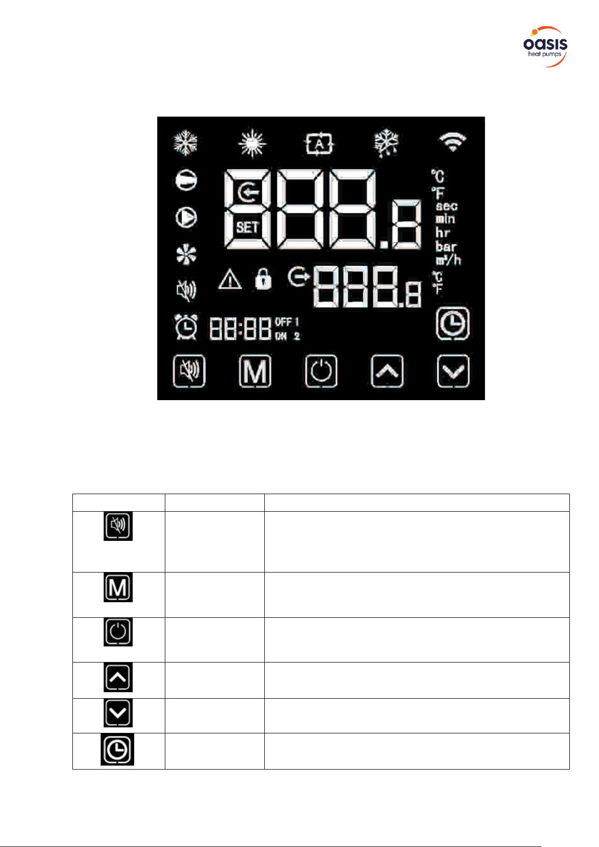
4.1 Interface display
4.2 Key and icon function instruction
4.2.A - Key function instruction
Symbol
Meaning
Function
Mute key
Under the heating mode or heating mode under the automatic
mode, the mute key operation is effective and used to enter and
exit the mute mode with one click.
Mode key
It is used to switch the unit mode, temperature setting, and
parameter setting.
On-off key
It is used to carry out startup & shutdown, cancel current
operation and return to the last level of operation.
Up key
It is used to page up, and increase variable value.
Down key
It is used to page down, and decrease variable value
Clock key
It is used as user clock, and to carry out timing setting.
INSTALLATION & INSTRUCTION MANUAL - INVERTER SERIES – I9, I12, I17, I19 - SWIMMING POOL HEAT PUMP UNIT
sales@sunloverheating.com.au
sunloverheating.com.au
12
4. USAGE AND OPERATION
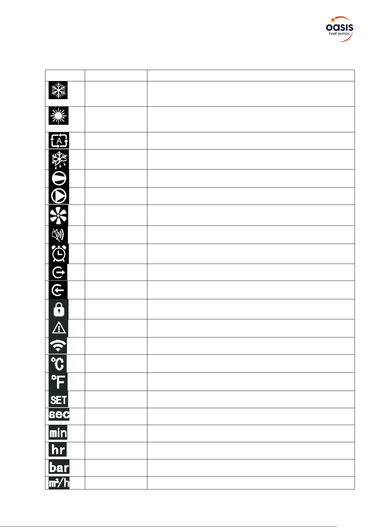
4.2.B - Icon function instruction
Symbol
Meaning
Function
Cooling
It will display during cooling (there is no limit to startup &
shutdown, and it is optional when the unit is cooling-only
unit or heating-and-cooling unit).
Heating
It will display during heating (there is no limit to startup & shutdown,
and it is optional when the unit is heating-only unit or heating-andcooling unit).
Automatic
It will display under the automatic mode (there is no limit to startup &
shutdown, and it is optional when the unit is heating and- cooling unit).
Defrosting
It will display in the defrosting process of the unit.
Compressor
It will display when compressor is started.
Water pump
It will display when water pump is started.
Fan
It will display when fan is started.
Mute
When the timing mute function is started, it keeps bright for a long
time. When it is in mute state, it will flash. Or else, it is off.
Timing
It will display after the user sets the timing, and multiple timing
intervals can be set .
Water outlet
When the axillary display area displays the water outlet
temperature, the light is on.
Water inlet
When the main display area displays the water inlet temperature, the
light is on.
Locking key
When the keyboard is locked, it is on.
Fault
In case of unit fault, it is on.
Wireless signal
When the unit is connected to WIFI module, it will display according to
the strength of WIFI signal
Degrees Celsius
When main display area or auxiliary display area displays
degrees Celsius, it is on.
Degrees
Fahrenheit
When main display area or auxiliary display area displays
degrees Fahrenheit, it is on.
Setting
When the parameter is adjustable, it is on
Second
When main display area displays second digit, it is on
Minute
When main display area displays minute digit, it is on.
Hour
When main display area displays hour digit, it is on.
Pressure
When main display area displays pressure, it is on.
Flow
When main display area displays flow, it is on.
INSTALLATION & INSTRUCTION MANUAL - INVERTER SERIES – I9, I12, I17, I19 - SWIMMING POOL HEAT PUMP UNIT
sales@sunloverheating.com.au
sunloverheating.com.au
13
4. USAGE AND OPERATION
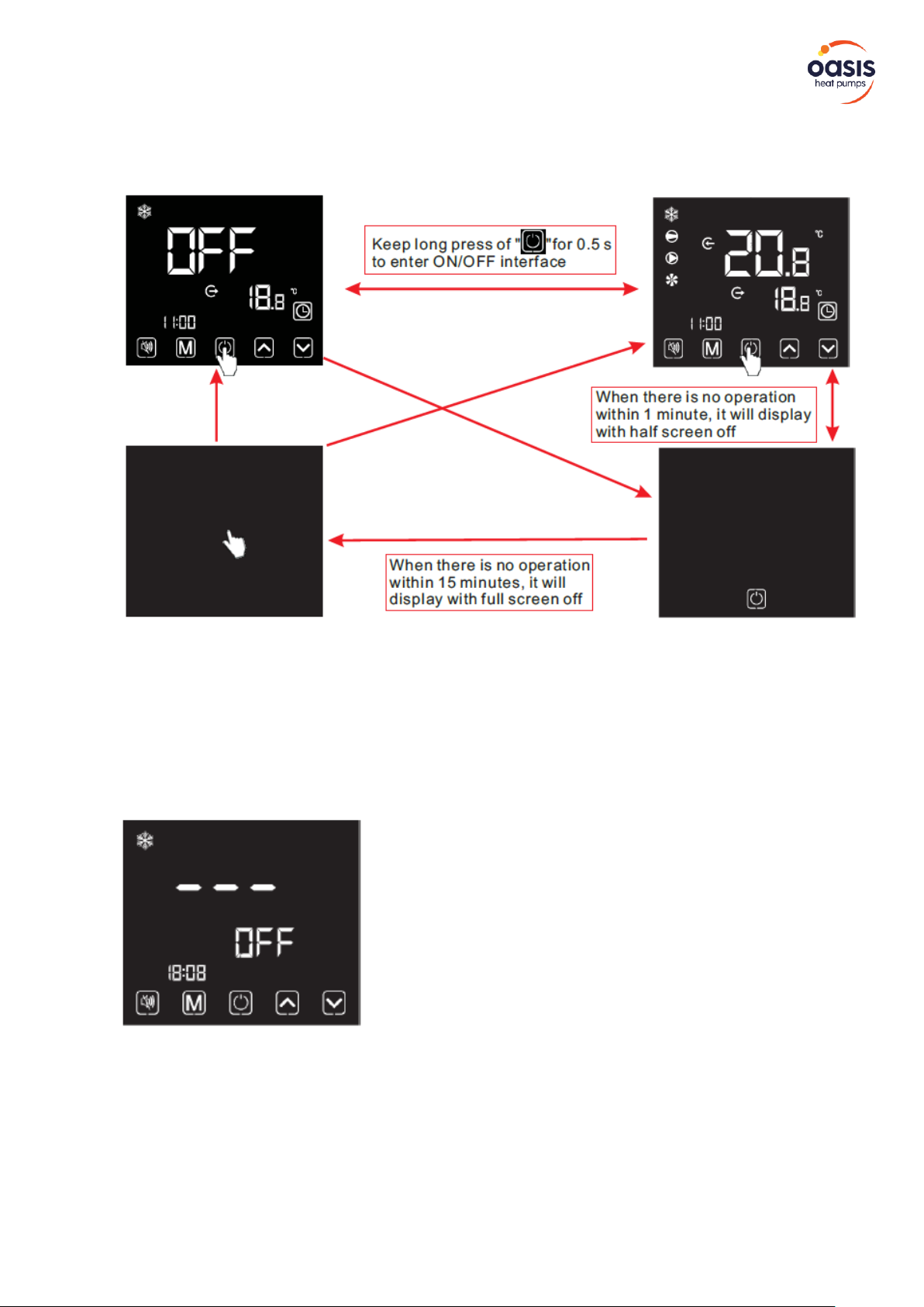
4.3 Startup & shutdown
Notes:
Startup & shutdown operation can only be conducted in the main interface.
When it displays with half screen off or full screen off, click any key for returning to ON/OFF main interface.
When the unit is started under the control of wire controller, if using the emergency switch to shut down, the
wire controller will display as follows:
Operations are the same as under ON/OFF main interface.
INSTALLATION & INSTRUCTION MANUAL - INVERTER SERIES – I9, I12, I17, I19 - SWIMMING POOL HEAT PUMP UNIT
sales@sunloverheating.com.au
sunloverheating.com.au
14
4. USAGE AND OPERATION
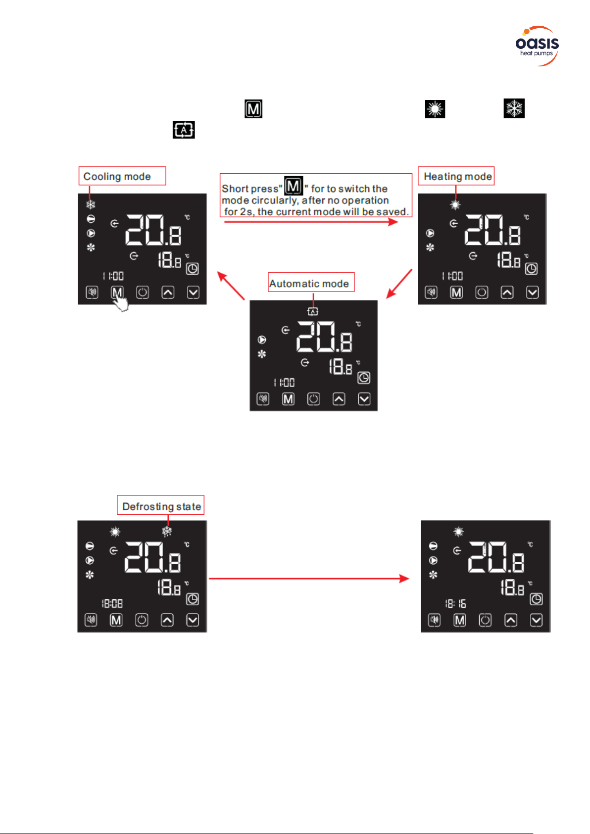
4.4 Mode switch
Under the main interface, Short press" "to switch the unit among heating “ ” , cooling “ ”
and automatic mode " ".
Operation descriptions:
1) Mode switch operation can only be conducted in the main interface.
2) When the unit is under the defrosting state, the defrosting symbol is on ,with the display
interface as follows:
Notes:
After completing the defrosting, the unit will be automatically switched to the heating/ automatic mode
(keeping consistent with the mode before defrosting).
During the defrosting, mode switch is available. And when switching the mode, the unit won't work under a
new mode until defrosting is completed.
 Loading...