

OSD-40DP
English
1. INTRODUC TION
OSD-4 0 D P is a dual pir outdoor wireless detector with int e l l ig e nt
solar charging technology. This detector adopts intellig ent multigrade digita l recognition technology and unique SLT calculation
to process the 2-way special pir signal and 1 way environmental
temperature signal to reach the topgallant detection and lowest
false and missing alarm. It can recognize waving object and real
human motion; resist direct or reflective sunshine and accommodate the false alarm caused by speedy hot and cool air.
OSD-40DP can operate in outdoor severe environment for long
term. 8 bands of sensitivities for option, can take on the weather
difference caus e d by rain, s now, hail, strong sunshine, gale etc,
it is a purely high-class outdoor detector worthy of selection and
usage.
2. BRIEFINTRODUCTION
- 2 Dual PYRO Sensors
- VLSI based electronics with movement speed spectrum analysis.
- 8 bands of sensitivities for option
- Anti direct or reflective sunshine
- Anti strongly mutative hot/cool air
- Pet immunity 25KG
- Digital environmental temperature detection
- Intelligent solar charging technology
3. SPECIFICATIONS
Power supply:
Current:
Warm up period
Install high:
Alarm time:
Anti RFI/EMI:
Anti-white light:
Low battery alarm:
Temp compensation: intelligent digital compensation
Temperature:
Humidity(RH):
Sensitivity:
Detect speed:
Radio emission
Frequency:
Encoding:
Dimensions:
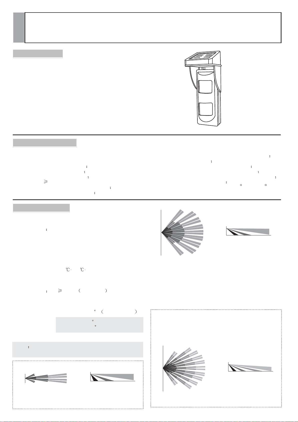
Coverage:
Note the factory lens is standard lens, but we have 3 other
lenses for option: pet imm unity; curtain & long range!
+1.5m
-1.5m
TOP VIEW
Wireless Intelligent 2 PIRs Outdoor Motion Detector With Solar
3*1.2V AAA Ni-MH Chargeable battery
Static ---200uA Alarm ---15mA
40s
1.5m.-2.4m
2s
0.1-500MHz/3V/m
>100000LUX
3.3V
-10 /+55
95%
8 grades adjustable
0.2m/s to 3.5m/s
200m Open space
315/433MHz etc.
PT2262
160mm*65mm*50.5mm
12m*12m 110 Standard Lens
12m*3m 12 (Curtain Lens)
12m*12m 110 (Pet Lens)
2m
SIDE VIEW
Curtain Lens
12m
Installation
- Purely wireless transmitting structure, easy installation
- Tamper&low voltage alarm
- IP65 water proof, high-strength optical system
- Lens for option: long range, curtain, pet immunity
- Installation way: wall mount, corner mount, ceiling mount
- Transmission frequency for option 315MHZ 433MHZ
- Mounting Bracket adjustment options: 90
+6m
-6m
TOP VIEW
+6m
-6m
TOP VIEW
Instructions
(
h) and 30 ( v)
2m
SIDE VIEW
Standard Lens
2m
Pet Lens
SIDE VIEW
Power
12m
12m
4. INSTALLATION GUIDE
Even though OSD-40DP can acco mmodate outdoor severe environments, the following factors shall be avoided during installation in order to get the reasonable detection:
Detector
No direct facing
/hot
source
Keep away from strong
electrical interferences
cold
Mount on a secure and
stable base/object
Keep away from
pressure
power
high
Incorrect Installation
(with pet immunitylens)
Don't install on the tree,
wire fence etc
Place without
sunshine s uch as
and umbrage
Avoid moving
enough
eave
etc
vehicles
1
3
corner rivet
wiring hole
Wiring hole
Wiring
2
Figure 1
Figure 4
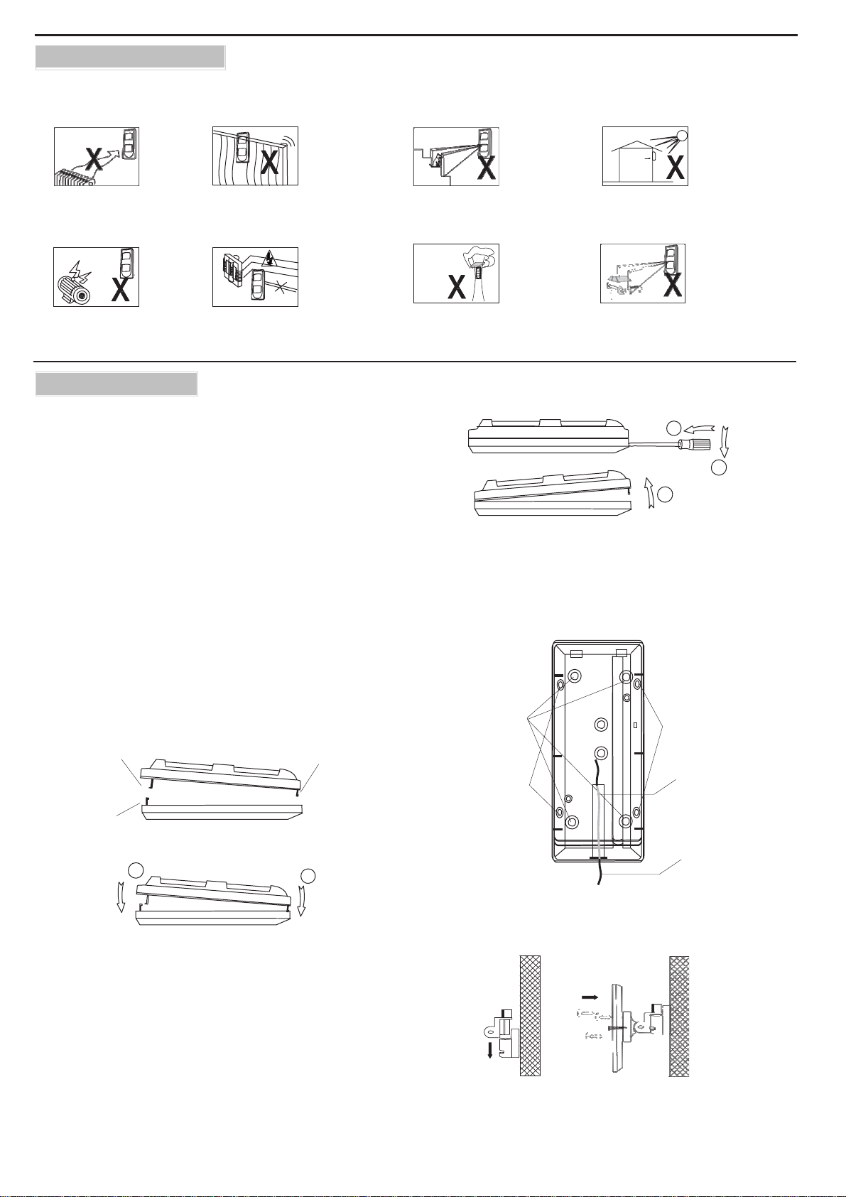
5. WALL FASTENING
In or d e r t o g e t t h e b e s t d e t e c t i o n a n d signal c overing scale,
t h e detector should be installed at 1.5-2.4 meters (height) and in
a c orrect direction a s F igure 1. E n s u r e t h a t t h e r e a r e n o
obstacles , trees w h ich c o u ld o b s t r uc t t h e wide ang l e d ete ctionview.
Release the screw and remove the front cover gently by hand.
If too tight, use a screw driver to prize the opening slot between
front cover and the base from the bottom side near to the screw
Loosen the f ixing s crew on the P CB refer t o f igure 3, break
through the relevant blind holes according to spot requirement
and i nstallation w ay (For example, blind holes for corner
installation must be broken through during corner installation;
and those for wall mount mus t be broken through during wall
mounting), and t hen f asten t he solar brack et onto t he wall
together, be attentive that the screws holes on bottom bracket
and s olar bracket shall be complie s on s ame position, don't be
dislocated or devious.
Top shell buckle A
Top shell buckle B
Bottom shell buckle A
2
1
Figure 2
Procedure for closing the cover:
Face the B shell buckle o f upper c over t o t he slot of lower
c o v e r, and f ac e A s hell buckle o f upper c over w ith A s hell
buckle of lower cover. Press the upper cover down to close
the detector.
Fasten the wall mount accessory bracket to a stable surface at
the correct installation height. Insert and twist the connection
accessory into the bracket section mounted on the wall. Fasten
the bracket section to the PIR housing. ( Figure 4)
Procedure for opening the cover:
1. Release the screw on the external cover
2. Insert the blade screw driver into the opening slot, press it and
wind it to the arrow direction, so that the external cover can be
opened.
Wall
rivet
corner
rivet
Figure 3
installation figure for wall mount bracket

6. INSTALLATION OF SOLAR BA TTER Y CABLE
Refer to the figure, cross the solar battery cable from the cablelead slot on backside of th e detecto r bottom cover, and then go
ac ross from the cable-lead hole o n bottom; connect it to the
relevant extremities o n P CB (Pay attention t o t he polarities)
Note: m u st l ead the cable according to the guide lines a bove,
never cross the cable from to p o f d e t e c t o r b y h a n d , f o r i t m a y
damage the air proof and cause false alarm or invalidation.
Warning if want to charge the battery by DC through the solar
battery input extremity, the voltage must be limited
within 0.8-2.0V, overload will damage the detector!
8.
Dip switch setting
DIP 1 When dip switch 1 is OFF , detector is in high s ensitivity mode;
When dip switch 1 is ON , detector is in low sensitivity mode.
DIP2 w he n dip switch is OFF , detector i s in nor mal oper ation mode ,
ie, in order t o reach the purpose o f e nerg y s aving, in operation mode ,
when detector is triggered alarm, the 2
later.
When dip switch 2 is ON , detector is in TEST MODE , ie, detector
can b e t riggered w hen a ny alarm s ignal accord with alarm c onditions is
detected.
This is for the convenience of installation and adjustment.
DIP3 DIP4
DIP3 DIP4 is combined switch mode
It is for detection of different pulse setting.
ts makeup is as below
DIP3 DIP4
OFF OFF
OFF ON
ON OFF
ON ON
Suggestion: during operation in different environments, please adjust the
detector to relevant setting in order to fulfill its best function.
DIP5 LED control
When i t is OFF LED is t ur n off to r each the purp os e of en ergy sa vi ng and
concealed installation.
When it is ON , LED is turn on.
Note: Strongly s
Encoding operation (communication with control panel)
40 seconds after power warm up, set t he control panel t o
"detector zone record mode" and then draw out the RECODE
jumper from OSD-40D P, a t t h i s time, d etector will se n d a n
alarm s ignal t o c ontrol panel, please c onfirm the e nc ode is
successful according to relevant operation on control panel
Do keep in mind!
SETTING
Pulse Mode
2 Pulse
3 Pulse
4 Pulse
5 Pulse
life w
uggest that
ill be shortened greatly!
nd
alarm shal l be performed 3 minutes
ON
1 2 3 4 5
Dip
switch
2 & 5 must be set to
“OFF”, or battery
Note: jumper cap doesn't need to insert
back af t e r en c ode succeeds, if not,
tamper function will disapear.
RECODE
7. PCB LAYOUT
DIP
switch
Data
set
Oscillation
Resistor
Regulation
Address
set
Trans m issio n
Module
Trans m issio n
Antenna (315M or
433M)
For solar battery connection
(care for the pola rities)
Vertical
Battery
PIR2
TAMPER
RECODE
Note: Don't touch the transmission module, transmission
antenna or PIR on PCB.
Installation of chargeable battery
1. Switch DIP5 to “ON” position.
2. Open the metal cap on battery box,
c o n n e c t t h e 3 * A A A battery group
(for option) to the m other b ase o n
det e c t o r and take care of its polarities.
After b attery connection, LED
doesn't flash, states that the polarity
is wrong or battery is bad.
Draw it out and m ak e a c onver se
connection, if LED doesn't l i g h t ,
must make a careful check and solve
the problem beforethe 3
rd
connection.
Walk test
Preparation:
after power connection, set DIP2 & DIP5 to
“ON”
1. Set different pulse modes refer to different environments.
Detector is with 8 kinds of operation modes as below:
DIP1 DIP3 DIP4
OFF OFF OFF
OFF OFF ON
OFF ON OFF
OFF ON ON
ON OFF OFF
ON OFF ON
ON ON OFF
ON ON ON
Mode
High sensitivity &2 Pulse
High sensitivity &3 Pulse High Risk
High sensitivity &4 Pulse
High sensitivity &5 Pulse Low Risk
Low sensitivity &2 Pulse Risk
Low sensitivity &3 Pulse Low Risk
Low sensitivity &4 Pulse
Low sensitivity &5 Pulse
Relevant environment
Very High Risk
Noisy Area
Extreme Noisy Area
2. Close the front cap, w hen LED indication is off, perform a
transverse movement to check the PIR performance through
the red LED, this can avoid
the dead angle of P IR
detection. PIR is in
highest sensitivity
when movement is
transverse to the
detector.
LED
PIR1
Adjust
input
position.
Risk
Red led
Battery input

Setting of compliance with other control panels External transmission antenna
Oscillation resistor set:
Compliance with other c o n t r o l p a n e l s c a n b e r e a ched through
regulation of oscillation resistance on encoding chips. Refer to
below figure, our oscillation resistance is with 3 modes: 4.7M,
3.3M, 1.5M
Data set:
C a n b e s e t b y th e j um pe rs as figure "DATA SET", among which
1=D3(A8);2=D2(A9);3=D1(A10);4=D0(A1 1), please s et it
correlatively according to the requirement of control panel
Address set:
Can by set by the jumpers as figure "ADDRESS SET" in order that
control panel can distinguish different zones
Data set
1 2 3 4
L
H
User can not take the liberty of enlarging the wireless
transmission distance by connecting an external
antenna without the authorization of
manufacturer.
It is not permitted by the FCC and may cause
uncompliance with the relate provisions of FCC
regulation. Such modifications could void the user’s
authority to operate the equipment. Please find the
FCC NOTE in this manual.
Oscillation
Resistor
Regulation
4.7M
3.3M
1.5M
External
Antenna
(Either connector is ok)
Address set
9. VERTICAL ADJUST
-1
1
+1
2.1 3.1 5.9
3.9 6 10.4
15
15
2.1m
4m
1.8 2.7 4.8
13
-1
1
+1
3.4 5.2 8.7
15
2.1m
4m
1.5 2.3 3.7
-1
1
+1
2.9 4.4 7
8
2.1m
4m
15
10. NOTES AND WARNINGS
Even the most sophisticated detectors can sometimes be defeated or may fail to activate due to: D C pow er failure /improper connection,
malicious mas king of the lens , tampering w ith the optical s ys tem, decreased sensitivity in ambient temperatures near that of the human
body and unexpected failure of a component or circuit. The above list includes the most common reasons for f ailure and it is re commended
that the detector and the entire alarm system be checked weekly to ensure proper performance.
An alarm s ystem s hould not b e regarded as a substitute for insurance. Home & property owners or renters should be prudent enoug h to
continue insuring their lives & property even though they are protected by an alarm system.
WARNING! Changes or modifications to this unit not expressly approved by the party responsible for compliance could void
the warranty. This device has been tested and found to comply with the limits for a Class B digital device, pursuant harmful
interference in residential installations. This equipment generates and uses or radiates radio frequency energy and if not
installed and used in accordance w ith the instructions, may cause harmful interference to radio and television reception.
There is no guarantee that interference will not occur in a particular installation. If this device does cause such interference,
which can be verified by turning the device off and on, the user is encouraged to eliminate the interference by one or more of
the following measures:
- Increase the distance between the detector and the electrical/electronic equipment.
- Connect the device to a different power socket which supplies power to the detector.
- Consult the dealer or an experienced radio/TV technician

FCC NOTE: This device complies with Part 15 of the FCC Rules. Operation is subject to th e following
two conditions:
1. This device may not cause harmful interference, and;
2. This device must accept any interference received, including interference that may cause undesired
operation.
The manufacturer is not responsible for any radio or TV interference caused by unauthorized
modifications to this equipment. Such modifications could void the user’s authority to operate the
equipment.
 Loading...