


-1
RFID CF Type Reader User’s Guide
Model Name: SLC-10200
Version: 1.0
Date: 2006.09.20
-2
Content
No. Item Page
1 Hardware environment 3
2 Demo software environment 4
3 How to contact us 12
Notice:
In order to avoid misuse or any unexpected damage, please read this
guide first.
-11
1. Hardware environment
(1) Product introduction
Sunlit’s RFID CF type reader is based on Hitachi µ-solution to develop.
It was operated at microwave 2.45GHz frequency band.
This is small and light, can be easily install to PDA, tablet PC.
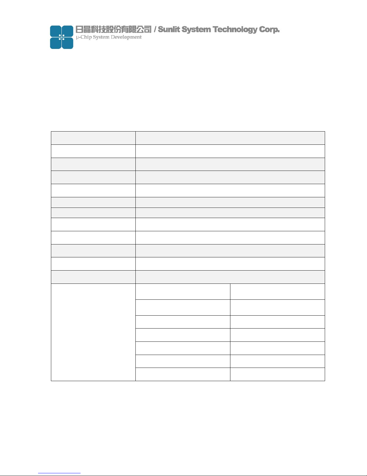
(2) Specification
Power Supply DC 3.3V +/-5%
Operating Environment
0°C ~45°C
Storage Environment
0°C ~60°C
Storing Humidity 5-85% RH
Static Consumption 90 mW
Dimensions 130 x 60 x 47 (mm)
Interface CF Type II
RF Output Power 20dBm
Frequency Range 2435-2465 MHz
Total Channel 31 channels
Modulation FHSS
Reading Distance
5 - 7 cm @PVC card
Connector U.FL connector
Frequency Range 2.4-2.4835 GHz
Impedance 50 ohm nominal
Gain 0dBi
Radiation Direction
Polarization Semi circular
Antenna
Beam Degree
90°

-4
(3) System requirement
Item Condition Quantity
Hardware requirement PDA support CF interface 1
Platform requirement Windows Pocket PC 2003 1
(4) How to install reader
Face the side with LED up, and insert it into PDA CF slot as shown in picture.
Normally always insert CF reader by put LED side up, but some PDA put CF slot at
reverse side, it means user needs to insert CF reader at back side. (LED down)

-5
2. Demo software environment
(1) Demo software introduction
This demo program can build a database include TAG ID、TAG information and
picture. It can be use to demo ex. material manager、In/out control for people… etc.
(2) Block diagram
Main Program
Tag ID
Data base
Picture Information
(3) Demo program operation
System requirement
Item Condition Quantity
PDA Support CF interface
64MB Flash ROM
64 MB RAM
1
System platform Windows Pocket PC 2003 1
RFID CF reader 1
Tag Include Hitachi µ-chip inlet 1

-6
Demo software contents
Item Description
Development
tool
Microsoft Visual Studio 2005 Traditional Edition
WinceDEMO.exe Main program
sunlitrfidppc.dll Dynamic Link Library file
Database.txt ID database file after ID saved
File contents
PIC [Folder]
A picture file includes different pictures
which correlated with each individual ID
Main Program Window
Function Description Function Description
ID
Display Tag ID when Tag be
read.
Delete
Delete registered database
Information
Edit information about Tag ID
Mode
Select scan mode
ON/OFF
Open/Close comport of
reader
Picture
Select picture correct with
ID
Mute
ON/Off reading sound
Clear
Clear text of ID & Message
window
Read
Trigger reader to scan
Tag
Database
Display registered database
Save
Save registered database
Message
Display status of reader

-7
Demo program operation
(a) Copy demo program files “WinceDEMO.exe” & “sunlitrfidppc.dll” to PDA and
store at same directory.
(b) Plug reader in CF slot of PDA

-8
(c) Click file “WinceDEMO.exe” and click “ON/OFF” to open device(Reader)
(d) Create a ID data base
Be sure the Mode is “Passive”
Put the tag on front side of reader, click “Read” to scan Tag ID and checking ID number
is showing on ID window.
Click “Picture”→ “Folder” to open location of picture that you want to correct with Tag
ID.Click ”Type” to select file type that you want than click picture file
※ Operation mode:
Passive: Click Read once and reader will scan once.
Active: Click Read once and reader will scan continuously.
It mean open device
successful
1
2
Cancel
Folder
File type
3
4
5

-9
(e) Editing information about the ID number on “Information” window.
Click “Save” and check “Tag DataBase” window to complete the data base
created procedure.
(f) You can follow the step (d) (e) to create some data base that you want.
(g) When you created the data base, the system was created 1 folder and 1 text file:
Item Description
Database.txt [text file] ID database file after ID saved
PIC [Folder]
A picture file storage folder about correlate
with ID database after picture saved.
Caution: Every PDA are different resolution so the picture is showed different size. If
you want it to be matched, you should modify the source code of the project. And
showing picture is Windows API,but it is not stable. Showing picture seveval times
may cause the Demo AP crashes.
1
2
It mean
database
created
successful

-11
DataBase.txt
(h) Set Mute function
Follow the figure click the” Mute” function check box, the mute function will enable.

-11
(i) Set Operation mode
Mode: Active
Click the “Mode” combo box and select “Active” item to enable active function
Click “Read”, if tag scanned by reader and the scan procedures will continuously.
Mode: Passive
Click “Mode” combo box select “Passive” item to enable passive function
Click “Read” and the reader scanning just only once.
Continue
Scanning
1
2

-12
(j) Delete data base
Click data you want to delete on Tag DataBase window
Click “Delete” and select “Yes” to delete data.
(k) Clear function
If click “Clear” than the text message on the ID and Message window will be clear.
(l) Disable device(Reader)
To confirm device is open.
Click “ON/OFF” to disable device.
1
2
3

-13
3. How to contact us
For further information or in case of difficulties please contact
Sunlit System Technology Corp.
www.sunlitcorp.com
8F1, NO19, LANE.120, SEC.1, Neihu Rd., Neihu Chiu Taipei Taiwan 114 R.O.C.
webmaster@sunlitcorp.com
TEL: 886-2-6600-6351
FAX: 886-2-6600-6765

-14
FEDERAL COMMUNICATIONS COMMISSION INTERFERENCE STATEMENT
This equipment has been tested and found to comply with the limits for a Class B digital
device, pursuant to Part 15 of the FCC Rules. These limits are designed to provide
reasonable protection against harmful interference in a residential installation. This
equipment generates, uses and can radiate radio frequency energy and, if not installed
and used in accordance with the instructions, may cause harmful interference to radio
communications. However, there is no guarantee that interference will not occur in a
particular installation. If this equipment does cause harmful interference to radio or
television reception, which can be determined by turning the equipment off and on, the
user is encouraged to try to correct the interference by one or more of the following
measures:
– Reorient or relocate the receiving antenna.
– Increase the separation between the equipment and receiver.
– Connect the equipment into an outlet on a circuit different from that to which the
receiver is connected.
– Consult the dealer or an experienced radio/TV technician for help.
CAUTION:
Any changes or modifications not expressly approved by the party responsible for
compliance could void the user's authority to operate the equipment.
This device complies with Part 15 of the FCC Rules. Operation is subject to the
following two conditions:
(1) This device may not cause harmful interference and
(2) This device must accept any interference received, including interference that may
cause undesired operation.
This equipment must not be co-located or operating in conjunction with any other
antenna or transmitter.
 Loading...