

The d etect or is a dua l pir out door wi reles s detec tor wit h intel ligen t
sol ar char ge te chnol ogy;i t can mat ch most o f the wir eless c ontro l
pan els dir ectly a nd all wi red con trol pa nels by w irele ss-to -wire d
rec eiver . T his d etect or adop ts inte llige nt mult igrad e
dig ital re cogni tion te chnol ogy and u nique S LT calc ula tion to
pro cess th e 2-way s pecia l pir sig nal and 1 w ay envi ronme ntal
tem perat ure sig nal to re ach the t opgal lant de tecti on and lo west
fal se and mi ssing a larm. I t can rec ogniz e wavin g objec t and rea l
hum an moti on; res ist dir ect or re flect ive sun shine a nd acco modat e the fal se alar m cause d by spee dy hot an d cool ai r.
The d etect or can op erate i n outdo or seve re envi ronme nt for lo ng
ter m. 8 band s of sens itivi ties fo r optio n, can ta ke on the w eathe r
dif fer ence ca used by r ain, sn ow, hail , str ong sun shine , gale et c,
it is a p urely h igh-c lass ou tdoor d etect or wort hy of sel ectio n and
usa ge.
INTR ODUCT ION
- Anti s trong ly muta tive ho t/c ool air;
-
-
-
-
-
Pet immunity up to 25kg (With particular pet lens)
18 bands Fres nel lens (Sta ndard wide angle lens)
Ant i UV ABS h ousin g
Ful ly-se aled op tical d esign
All -dire ction al brac ket ins talla tion: H 90°an d
V30 °ad justa ble
- 2 Dua l PYRO Se nsors
- VLS I bas ed elec troni cs with m oveme nt
spe ed spec trum an alysi s.
- 8 ban ds of sen sitiv ities f or opti on ;
- Digital environmental temperature detection ;
- Anti s trong ly muta tive ho t/c ool air;
- Int ellig ent sol ar char ge te chnol ogy ;
- Anti d irect o r refle cti ve suns hine;
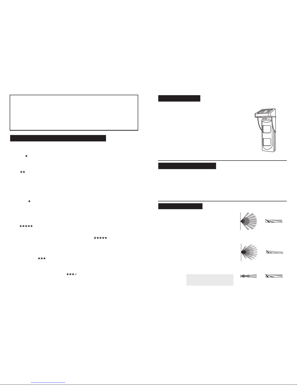
BRIE F INTRO DUCTION
+1.5 m
-1.5 m
2m
12m
Cur tain Le ns
TOP VIE W
SID E VIEW
+6m
-6m
2m
12m
Sta ndard L ens
TOP VIE W
SID E VIEW
+6m
-6m
2m
12m
Pet L ens
SID E VIEW
TOP VIE W
att ery pow er : 3.7V l ith ium cha rgabl e bat tery,
Cur rent: Stat ic -- -70uA Ala rm ---2 0mA
DC Po wer Inp ut: 5.5 V@40- 50mA So lar pan el
Warm up per iod: 4 0s
Ins tall hi gh: 1.8 m-2.4 m
Ala rm time : 2s
Ant i RFI/E MI: 0.1 -500M Hz/3V /m
Ant i-whi te ligh t: >100 000LU X
Low b atter y alarm : 3.2V
Temp comp ens ation : intel ligen t dig ital co mpens ation
Tempera ture: -1 0℃/+5 5℃
Hum idity (RH): 9 5%
Sen sitiv ity: 8 gr ades ad justa ble
Det ect spe ed: 0.2 m/s to 3. 5m/s
Rad io emis sion : ≥20 0m (Open s pace)
Freque ncy : 315/4 33MHz e tc.
Enc oding : PT226 2
Dim ensio ns: 160 mm*65 mm*50 .5mm
Cov erage : 12m*1 2m 110°(Sta ndard L ens)
12m *3m 12° (Cur tai n Lens)
12m *12m 110° ( Pet Len s)
SPEC IFICATIONS
Installation Guide
Outdoor Intelligent Wireless
Detector With 2 PIR
General Introduction On Outdoor Application
stabl e if i ns talle r ca n pay att en ti on to the m:
Thi s dete cto r is rem arkable in func tio n, but the fol low ing notic es can ma ke i t mo re
High weed s and shrubbe ry in detecti on range may wave in wind and cau se false alarm, especially
for t hose de tecto rs oper ating i n horiz on tal f an a rea , so kee p cutt ing on weeds a nd shru bbe ry.
WEEDS
Insects will trigge r fals e alar m when they cli mb into detec tor or stay on lens, whil e those staying
away from det ector s can't trigg er alarm. If ther e is interfer enc e from in sec ts, please r e-ins tall
detecto r or use in sectici de. And pl ease adopts stri ctl y seal ed com ponents on those drill ed hol es
or gl ass glu e aroun d detec tor.
INSECTS
Mov ing car i n detec tion ra nge may t ri gge r fa lse a larm to d etect or.
CAR
Detec tor is sensit ive to change fro m tempera ture diffe rence in dete ction area, if target temperature
is very close to prev ious envi ronme nt temper ature, there will be no temperature chan ge, det ect or
sen sitiv ity wil l be lowe red and w ill not b e tr igg er ed so metim es when t here is i ntr us ion .
INSUFFICUENT TEMPERATUR E DI FF ER EN CE
Len s becom es easi ly dirt y when us ed outd oor, so pl eas e chec k the len s from ti me to time in
ord er to avo id alar m miss ca used by l ow sens itivi ty f rom d ir ty le ns.
DIRT ON L EN S
Det ector w ill tri gger fa lse ala rm easil y if install ation ba se ca n be interf ered by vibr ation,
thi s is the re ason wh y some de tectors insta lle d near to st ree t can cau se fal se ala rm eas ily.
UNSTAB LE I NS TALL ATI ON BASE
Sudden rainst orm ca n cool the hot pitch road or surface of other roads quickl y. And al l dete cto rs
can de tect rain in th e sky, but de tector with down vi ew window can even detect water on gr ound,
whi ch will b ring mu ch more interf ere nce to detec tor s outd oor th an tha t mou nte d on wall , so
eve rythi ng will l ower it s tempe ra tur e si mil ar to water, human body or ca rs aft er pou ring from
rai n can off er very l itt le temp eratu re g ap fo r de tec tion, s o sensi tivit y wil l be l owe re d a lot .
RAIN

Adj ustme nt on sol ar pane l ang le
Accor ding to different altit udes area and act ual
env ironm ent, so lar pan el can be a dj ust ed t o
get t he max su nshin e
Sol ar pane l can be ad juste d withi n 135°h orizo ntall y
ON DIP
1 2 3 4
BLA CK
RED
Sol ar Pane l
GND
SLR( +12V )
INSTALLATION OF SOLAR BATTERY CABLE
As figure , pass the solar pane l connect ing cable
thr ough th e cable s lot on back of de tector and
con nect it o nto the r ele vant terminal s on PCB
(Tak e care of p ola ri tie s)
Note: plea se do lead cable acc ording to above instru ction,
don't dril l holes to lead cabl e on top/ba ck/side of detecto r,
oth erwis e it will d amage t he wate r-proo f struc ture an d
cau se fals e alarm o r malfu nctio n.
2.O pen the f ront co ver: re lease t he bott om s cre w
ant icloc kwise b y a plus-scr ew- driver( no nee d to twis t
out fro m cover), lift ou t the cove r from bottom and then
turn on the pow er sw itch, r ed LE D will fl ash for 4 0
secon ds as warm-up , when LED stops, wal king test can
be performed. (Please refer to following content on other
setti ng). Then, close the cover as figure a nd ti gh ten t he
scr ew. (Ref er to bel ow figu re fo r detai ls )
1.L oose th e botto m
scr ew with c ross- type
scr ew driv er
1
2.D isclo se the co vers
fro m botto m
4.M ake goo d align ment of
bot tom par ts of fro nt and
bot tom cov ers, an d then pr ess
dow n the top p art of co vers,
det ector c an be clo sed wel l.
power switch
3.Tu rn on the p ower
swi tch
O
N
DIP
1 2 3 4
-1
+1
0
1.Drill a hole on wall and insert the rubber stopper int o th e
hol e, fast en the de tecto r by 3 scre ws .
Warni ng: thi s termi nal can o nly be in put wit h
5- 5. 5VDC po wer or ou r solar b atter y, illeg al
voltage might cause permanent damage to detector.
3.D ecomp osing steps
INSTALL ATI ON GUIDE
Eve n thoug h Detec tor can a ccomm od ate o ut doo r sever e envir onmen ts, t he f oll ow ing f actor s
sha ll be avo ided du ring in stall -atio n in o rde r to g et th e reaso nable d ete ction :
No di rect fa cing
col d/hot s ource
Mou nt on a sec ure and
sta ble bas e/obj ect
ele ctric al inte rfere nces
Kee p away fr om stro ng
Inc orrec t Insta llati on
(wi th pet im munit y lens)
Don 't inst all on a tr ee
WALL FASTE NING
In or der to ge t the max imum de tecti on r ang e, p lea se inst all det ect or at 2.1 m heigh t and adj ust
PCB p ositi on to “0” m ark ver tical ly. Howe ver, det ector c an be ins tal led at 4m s uperl ative ly.
Ple ase gua rante e that th ere is no s ou rce o f in ter feren ce near by and th e fro nt v iew o f de tec tor
is wi de and cl ear.
Kee p away fr om high
pre ssure p ower
Avoid m oving v ehicl es
Pla ce with out eno ugh
sun shine s uch as ea ve
and u mbrag e etc
Low he ight, s hort di stanc e
2m
1.5m
3m
2.6m
0m 1.5m 3 m 4.5m 6m
7.5m
9m 10.5m
0m
Suit able he ight
2m
1.5m
3m
2.6m
0m 1.5m 3 m 4.5m 6m
7.5m
9m 10.5m
0m
On in stall ation h eight
Rec ommen ded ins talla tion he ight is 1 .8-2. 4m
Too hig h to be wit h blind a rea
2m
1.5m
3m
2.6m
0m 1.5m 3 m 4.5m 6m
7.5m
9m 10.5m
0m
Dete ction d istan ce migh t
be sho rtene d to move ment
from t hese di recti ons
Lowe st sens itive
Most s ensit ive
On in stall ation a ngle
Det ectio n is with m echan ical di ffere nce to in trusi on
ang les
Door
Unre asona ble
inst allat ion pos ition
Door
Best i nstal latio n
On in stall ation p ositi on
Det ectio n is not se nsiti ve
to in trusi on from w indow
in th is way
Det ector i s sensi tive to
int rusio n from do or and
win dows in t his way
X
Detec tor
X
X
X
A
D
H
U
G
G
E
R
R
O
X
X
X
X
Wind ow
Wind ow

-1
+1
0
STU DY butto n
ID registration (coding with alarm control
panels)
You can match detector with control panel before
ins talla tion. W hen con tro l panel e nt ers i nt o
lea rning s tatus , you can p ress do wn STUD Y
but ton to tr igger d etect or and re gi ste r it s ID
int o contr ol pane l.
PCB LAYOUT AND WIRELESS CODING
Sol ar powe r
inp ut term inals
Bat tery bo x
(wi th bat)
Pow er Swit ch
DO NOT TOU CH
Tampe r
Tran smiss ion
Mod ule
Tran smiss ion
Ant enna (3 15M or 43 3M)
Res istor
Reg ulati on
Dat a set
DIP sw itch
Sel ect
Bat tery in put
ON DIP
1 2 3 4
-1
+1
0
DO NOT TOU CH
PIR 2
PIR 1
Proper coding data can be obtained by “DATA SET”
pin s for con trol pa nel re cogn ition: 1=D 3;2 =D2;
3=D1; 4=D0 (Cod es under some special proto cols
mig ht be inv erse)
Setting of compliance with other control panels
Osc illat ion res istor set:
Com plian ce with o ther co ntrol p anels c an be
reached through regulation of oscillation resistan ce
on en codin g chips . Refer t o left fi gure, o ur
osc illat ion res istan ce is wit h 3 modes :
PT2 262 pro tocol : 4.7M、3. 3M、1.5M
EV1 527 pro tocol : 430K、33 0K、100K
Data se t:
DIP SWITCH SETTING
Dip switc h 1: (sensiti vity control)
Whe n dip swi tch 1 is se t to OFF,
detector is in high sensitivity mode.
Whe n dip swi tch 1 is se t to ON,
detector is in low sensitivity mode.
Dip s witch 2 : (Sett ing on PI R pulse d etect ion)
Whe n dip swi tch 2 is se t to OFF, dete cto r is in 2
pul ses mod e.
Whe n dip swi tch 2 is se t to ON, de tecto r is in 3
pul ses mod e.
ON DIP
1 2 3 4
Signa l processin g statem ent: this detector ado pts digital
dir ect sig nal-a nalys is tech nolog y, digit al proc essin g
CHI P wil l analy ze those si gnals det ected by sen sors in
fre quenc ies, sc ope, po larit y etc, and mak e comp arison
wit h those u sual pe t- data i n data ba se and dr aw real
con clusi on on bod y intru sion. S o, here , pulse s ettin g
is just a general ind ex, might not be actual pul se quant ity
dur ing sig nal pro cessi ng.
1
2
3
4
5
6
Fas t detec tion on t arget
Bet ter way t o avoid
fal se alar m
Whe n set to 2 pu lse countin g, det ecto r is in hig h
sen sitiv ity, det ect ion of 2 in trusi on puls es may
cau se alar m usual ly.
Whe n set to 3 pu lse cou nting , detec tor is in l ow
sen sitiv ity, ala rm wi ll be tri ggere d only wh en 3
int rusio n pulse s are det ected .
4.7 M
(430 K)
3.3 M
(330 K)
1.5 M
(100 K)
Osc illat ion
res istor s et
Dat a set
ON DIP
1 2 3 4
-1
+1
0
1 2 3 4
L
H
Rev .0 0 16/35
Even th e most sophi sticat ed detecto rs can somet imes be defe ated or may fai l to activat e due to: DC powe r failure /improp er
conn ection, m aliciou s masking of th e lens, tampe ring with the optical syst em, decreased sensi tivity in ambient te mperatu res
nea r that of t he huma n body an d unexp ected f ailur e of a comp onent o r circu it. The ab ove lis t inclu des the m ost com mon
reas ons for fail ure and it is rec ommende d that the dete ctor and the en tire alar m system be che cked week ly to ensure pr oper
per forma nce.
An alar m system sho uld not be reg arded as a subs titute fo r insu rance. Ho me & propert y owners or ren ters shou ld be pruden t
eno ugh to co ntinu e insur ing the ir live s & prope rty eve n thoug h they ar e prote cted by a n alarm s ystem .
WARNI NG! Cha nges or m odifi catio ns to thi s unit no t expre ssly ap prove d by the part y resp onsibl e for co mplianc e could
voi d the war ranty. Th is devi ce has be en test ed and fo und to co mply wi th the li mits fo r a Class B d igita l devic e, purs uant
har mful in terfe rence i n resid entia l insta llati ons. Thi s equip ment ge nerat es and us es or rad iates r adio fr equen cy ener gy
and i f not ins talle d and use d in acco rdanc e with th e instr uctio ns, may c ause ha rmful i nterf erenc e to radi o and tel evisi on
rec eptio n. There i s no guar antee t hat int erfer ence wi ll not oc cur in a pa rticu lar ins talla tion. I f this devic e does cause su ch
int erfer ence, w hich ca n be veri fied by t urnin g the dev ice off an d on, the u ser is en coura ged to el imina te the in terfe rence
by on e or more o fthe fo llowi ng meas ures:
- Inc rease t he dist ance be tween t he dete ctor an d the ele ctric al/el ectro nic equ ipmen t.
- Con nect th e devic e to a diffe rent po wer soc ket whi ch supp lies po wer to th e detec tor.
- Con sult th e deale r or an exp erien ced rad io/TV te chnic ian
NOTE S AND WAR NINGS
Dip switc h 3: ( m ode selecti on )
When dip sw it ch 3 is set to OFF, detector is i n US E mode.
When dip sw it ch 3 is set to ON, de te ct or is in TE ST mode.
DIP 4 LED con trol
When it is “OFF”LED is tu rn off to re ach th e purpose of en ergy sa ving a nd conceal ed inst all atio n.
Whe n it is “ON”, LE D is turn o n.
Note : after inst allatio n and walkin g test finis hed, dip swi tch 3 and 4 shoul d be set to OFF mode in or der to exten t
bat tery li fe!
-1
0
+1
2.13.15.9
15
3.9
610.415
2.1m
4m
-1
0
+1
1.82.74.813
3.45.28.715
2.1m
4m
-1
0
+1
1.52.33.78
2.94.4
7
15
2.1m
4m
VERT ICAL ADJ UST
Adj ustme nt can be ma de thr ough the moving of
PCB u p and dow n as the le ft figu re in ord er to
rea ch the be st dete ction
ON DIP
1 2 3 4
-1
+1
0
Det ector c an be
Verti cal Adju st:30 °
bac kward a nd
for wards a ccord ing
to actual envi ronment
Det ectio n angle c an
be Ho rizon tal
Adj ust: wi thin 18 0°
acc ordin g to actu al
env ironm ent。
Adj ustme nt on det ectio n angle
Red l ed
Pre parat ion: be fore te st, ple ase do set d ip switch 3 & 4 to ON posi tion and
choose proper sensitivity and pulse counts acccording to installation environment
and d etcti on requ ireme nt, in or der tha t detec tor can o btain b est ope ratio n.
Close the front cap, when LED indication is off, perform a transverse movement
to ch eck the P IR perf orman ce thro ugh the red LED , this can avo id the dead
ang le of PIR d etect ion. PI R is in hig hest se nsiti vity wh en move ment is
tra nsver se to the d etect or.
WALK TE ST
 Loading...