


RFID RF Module User’s Guide
Model Number: SLF-10100
Model Name: RF Module v4.0
Edition version: 1.0
Date: 2006.11.28

Regulatory Approvals
FCC Statement
This equipment has been tested and found to comply with the limits for a Class B digital
device, pursuant to Part 15 of the FCC Rules. These limits are designed to provide reasonable
protection against harmful interference in a residential installation.
This equipment generates, uses and can radiate radio frequency energy and, if not installed and
used in accordance with the instructions, may cause harmful interference to radio communications. However, there is no guarantee that interference will not occur in a particular installation.
If this equipment does cause harmful interference to radio or television reception, which can be
determined by turning the equipment off and on, the user is encouraged to try to correct the
interference by one of the following measures:
Reorient or relocate the receiving antenna.
Increase the separation between the equipment and receiver.
Connect the equipment into an outlet on a circuit different from that to which the receiver
is connected.
Consult the dealer or an experienced radio/TV technician for help.
To assure continued compliance, any changes or modifications not expressly approved by the
party responsible for compliance could void the user's authority to operate this equipment.
(Example - use only shielded interface cables when connecting to computer or peripheral
devices).
FCC Radiation Exposure Statement
This equipment complies with FCC RF radiation exposure limits set forth for an uncontrolled
environment. This equipment should be installed and operated with a minimum distance of 20
centimeters between the radiator and your body.
This device complies with Part 15 of the FCC Rules. Operation is subject to the following two
conditions:
(1) This device may not cause harmful interference, and
(2) This device must accept any interference received, including interference that may cause
undesired operation.
This transmitter must not be co-located or operating in conjunction with any other antenna or
transmitter.
The antennas used for this transmitter must be installed to provide a separation distance of at
least 20 cm from all persons and must not be co-located or operating in conjunction with any
other antenna or transmitter.
Channel
The Wireless Channel sets the radio frequency used for communication.
•Access Points use a fixed Channel. You can select the Channel used. This allows you to
choose a Channel which provides the least interference and best performance. In the USA
and Canada, 11 channel are available. If using multiple Access Points, it is better if adjacent
Access Points use different Channels to reduce interference.
• In "Infrastructure" mode, Wireless Stations normally scan all Channels, looking for an
Access Point. If more than one Access Point can be used, the one with the strongest
signal is used. (This can only happen within an ESS.)
• If using "Ad-hoc" mode (no Access Point), all Wireless stations should be set to use the
same Channel. However, most Wireless stations will still scan all Channels to see if there
is an existing "Ad-hoc" group they can join.
Index
No. Item Page
1 Hardware 03
2 Software Operation 06
3 How to Contact Us 17
4
5
6
7
Notice:
In order to avoid misuse or any unexpected damage, please read this
guide first.
This device complies with Part 15 of FCC Rules. Operation is subject to
the following two conditions:
(1)This device may not cause harmful interference ,and
(2)This device must accept any interference received, including
interference that may cause undesired operation
-2
1. Hardware
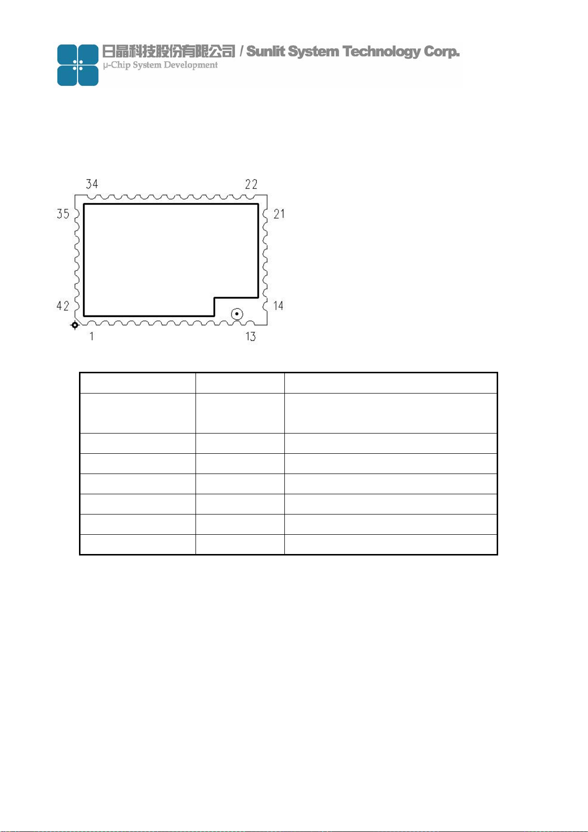
(1) Pin Description
Pin No. Pin Name Pin Function
1,2,5,11~25,
27~29,31~38
3 LED LED Display
4,6,7,8,26,30 NC No Connect
9 TXD Transmitter Output For The Serial Port
10 RXD Receiver Input For The Serial Port
39 PEN Power Supply Enable
40~42 VCC Power Supply
GND Ground
-3
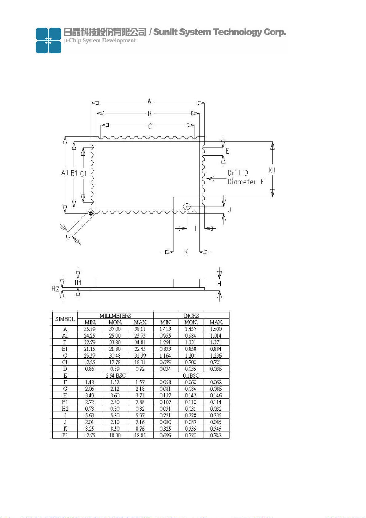
(2) Package Outline
Figure: Package Outline – 42 Pin 37mm x 25mm x 3.6mm Surface Mount Module
-4
(3) Specification
Power Supply Voltage DC 4.5V ~ 6.5V 500mA
RF Output Power 100 mW (Contact)
Trigger Mode Active & Passive
LED Lamp Power on & Read TAG(Pin Output)
Interface RS-232(TTL Level)
Pin Output 44 Pin
PCB Layer 4 Layer
Outer Antenna U.FL Connector
Operation Temperature 0 C ~ 45 C
Storage Temperature 0 C ~ 60 C
Frequency Range 2.40 GHz ~ 2.483 GHz
Environment Requirement Storing Humidity 5-85%RH(no condensation allowed)
Dimensions 37 x 25 x 2.8 (mm)
-5

2. Software Operation
(1) Environment
Antenna
Load board
RFID Module
(2) Operation Requirement
Item Condition
PC
RS232
Interface
DC
Power
CPU≧ Intel Pentium Ⅲ
RAM≧128 MB
CD/DVD-ROM
Operation System
Windows XP
Windows 2000 SP4
-6

(3) Software introduction
This software program can build a database include TAG ID、TAG information and
picture.It can be use to demo for material management、access control… etc.
Software contents
Item Description
Development tool Microsoft Visual Studio 2005 Traditional Edition
DemoDTR.exe Main program
Sunlitrfid.dll Dynamic Link Library file
File contents
Database.txt ID database file
A picture file includes different pictures which
PIC [Folder]
correlated with each individual ID
System requirement
Item Condition
CPU≧ Intel Pentium Ⅲ
Personal Computer
Operation System
RAM≧128 MB
CD/DVD-ROM
Windows XP
Windows 2000 SP4
-7

Main Program Window
Item Description Item Description
Port Name
Open/Close
Find
Operation
Mode
Mute
Read Tag
Delete
Picture
Show Device Comport
Open & Close Device Comport
Finding Comport when device
add
Select Active or Passive
Operation mode
Disable & Enable reading sound
Trigger reader to scan tag
Delete database
Select picture correct with ID
Save
Clear
Exit
Tag Data
Base List
Tag
Information
Read Tag
ID
Message
Save registered database
Clear text of Message window
Exit program
Display registered database
Edit information about Tag ID
Display Tag ID when Tag be
read.
Display status of reader
-8

Block Diagram
(4) Software Operation
(a) Copy software program files “DemoDTR.exe” & “sunlitrfid.dll” to PC and store at same
directory.
-9

(b) Connect RS-232 cable & DC 5V power adaptor to reader.
(c) Double click file “DemoDTR.exe” to open the demo program window.
(d) Choose “Port Name” , from what the Device connected comport of PC.
This example port name is “COM4” and click “Open” to open device(reader)
2
1
-10

(e) When device was opened, then Open item will change to Close
(f)Create a data base.
Set operation mode to “Passive”
※Passive: Click “Read Tag” once and reader will scan once.
-11

Click “Read Tag” to read Tag and Tag ID will show on Message window
Tag ID
Choose picture that you want to correct with Tag ID.
Click “Picture” to select picture.
※This is based on the pictures that each User’s PC has, we do not provide any picture.
User needs to put pictures in PC in advance.
1
2
3
-12

After choose picture, edit Tag Information and click “Save”.
1
2
When click Save, you will see the register data on “Tag DataBase List” window.
It means data registered successfully.
Register data
-13

(g) Delete data base
Click data base you want to delete and click “Delete”
2
1
3
When delete the register data, you will see the “Tag DataBase List” window is no data.
-14

(h) Clear information
When you click “Clear”, the message of “Message” & “Tag DataBase List” window will
be clear.
(i) Set operation mode to “Active”
1
※Active: Click “Read Tag” once and reader will scan continuously.
-15

3
2
Click “Read Tag” once, Reader will read tag ID continuously until you remove tag.
-16

(j) Set Operation mode to “Mute“
Check “Mute” box to enable mute function.
3. How to Contact Us
For further information or in case of difficulties please contact
Sunlit System Technology Corp.
www.sunlitcorp.com
8F, No.19, Lane 120, Sec.1, Neihu Rd., Taipei Taiwan 114 R.O.C.
webmaster@sunlitcorp.com
TEL: 886-2-66006351
FAX: 886-2-6600-6765
-17
 Loading...