

Page 1
INSTALLATION
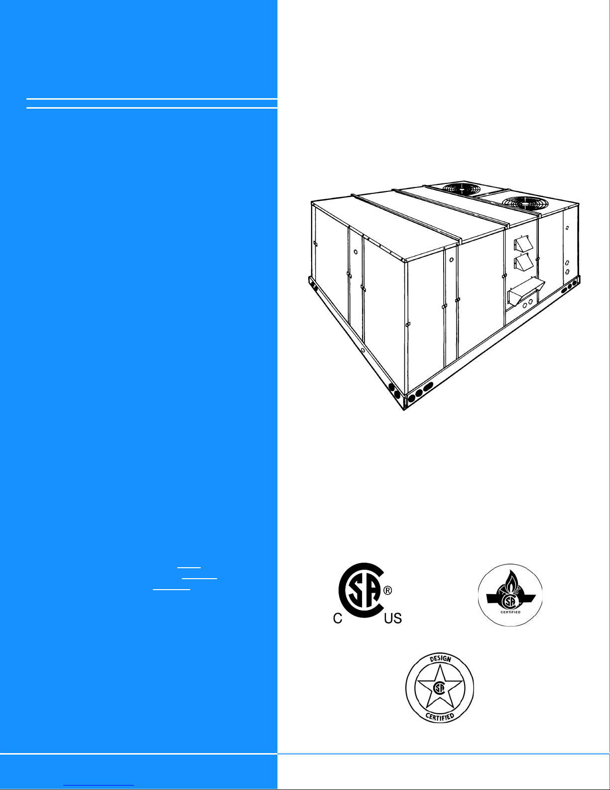
SUNLINE™ 2000
GAS/ELECTRIC SINGLE PACKAGE
MANUAL
CONTENTS
GENERAL . . . . . . . . . . . . . . . . . . . . . . . . . . . . . . . . . . . .4
SAFETY CONSIDERATIONS . . . . . . . . . . . . . . . . . . . . .4
INSPECTION . . . . . . . . . . . . . . . . . . . . . . . . . . . . . . . . . .4
REFERENCE . . . . . . . . . . . . . . . . . . . . . . . . . . . . . . . . . .4
RENEWAL PARTS . . . . . . . . . . . . . . . . . . . . . . . . . . . . .5
APPROVALS . . . . . . . . . . . . . . . . . . . . . . . . . . . . . . . . . .5
PRODUCT NOMENCLATURE . . . . . . . . . . . . . . . . . . . .6
INSTALLATION. . . . . . . . . . . . . . . . . . . . . . . . . . . . . . . .7
OPERATION . . . . . . . . . . . . . . . . . . . . . . . . . . . . . . . . .41
START-UP (COOLING) . . . . . . . . . . . . . . . . . . . . . . . . .47
START-UP (GAS HEAT) . . . . . . . . . . . . . . . . . . . . . . . .48
TROUBLESHOOTING. . . . . . . . . . . . . . . . . . . . . . . . . .50
See the following pages for a complete Table of Contents.
AIR CONDITIONERS
MODELS: DM180, 240 & 300
NOTES, CAUTIONS AND WARNINGS
The installer should pay particular attention to the words:
NOTE, CAUTION, and WARNING. Notes
clarify or make the installation easier. Cautions
prevent equipment damage. Warnings
installer that personal injury and/or equipment damage
may result if installation procedure is not handled properly.
CAUTION: READ ALL SAFETY GUIDES BEFORE YOU
BEGIN TO INSTALL YOUR UNIT.
SAVE THIS MANUAL
are intended to
are given to alert
are given to
284806-YIM-A-0107
Page 2

TABLE OF CONTENTS
284806-YIM-A-0107
GENERAL . . . . . . . . . . . . . . . . . . . . . . . . . . . . . . . . . . . . 4
SAFETY CONSIDERA TIONS
INSPECTION
REFERENCE
RENEWAL PARTS
APPROVALS
. . . . . . . . . . . . . . . . . . . . . . . . . . . . . . . . . . 4
. . . . . . . . . . . . . . . . . . . . . . . . . . . . . . . . . . 4
. . . . . . . . . . . . . . . . . . . . . . . . . . . . . . 5
. . . . . . . . . . . . . . . . . . . . . . . . . . . . . . . . . . 5
PRODUCT NOMENCLATURE
INSTALLATION
. . . . . . . . . . . . . . . . . . . . . . . . . . . . . . . . 7
. . . . . . . . . . . . . . . . . . . . . . 4
. . . . . . . . . . . . . . . . . . . . . 6
INSTALLATION SAFETY INFORMATION: . . . . . . . . . . . 7
LIMITATIONS. . . . . . . . . . . . . . . . . . . . . . . . . . . . . . . . . .7
LOCATION . . . . . . . . . . . . . . . . . . . . . . . . . . . . . . . . . . . .8
RIGGING AND HANDLING . . . . . . . . . . . . . . . . . . . . . . .9
CLEARANCES . . . . . . . . . . . . . . . . . . . . . . . . . . . . . . . . .9
DUCTWORK. . . . . . . . . . . . . . . . . . . . . . . . . . . . . . . . . .10
FIXED OUTDOOR AIR INTAKE DAMPER . . . . . . . . . .10
CONDENSATE DRAIN. . . . . . . . . . . . . . . . . . . . . . . . . .11
COMPRESSORS . . . . . . . . . . . . . . . . . . . . . . . . . . . . . .11
FILTERS. . . . . . . . . . . . . . . . . . . . . . . . . . . . . . . . . . . . .11
SERVICE ACCESS . . . . . . . . . . . . . . . . . . . . . . . . . . . .11
THERMOSTAT. . . . . . . . . . . . . . . . . . . . . . . . . . . . . . . .13
SPACE SENSOR . . . . . . . . . . . . . . . . . . . . . . . . . . . . . .13
POWER AND CONTROL WIRING. . . . . . . . . . . . . . . . .13
OPTIONAL ELECTRIC HEAT . . . . . . . . . . . . . . . . . . . .13
OPTIONAL GAS HEAT . . . . . . . . . . . . . . . . . . . . . . . . .14
GAS PIPING. . . . . . . . . . . . . . . . . . . . . . . . . . . . . . . . . .14
GAS CONNECTION. . . . . . . . . . . . . . . . . . . . . . . . . . . .15
L.P. UNITS, TANKS AND PIPING . . . . . . . . . . . . . . . . .16
VENT AND COMBUSTION AIR HOODS. . . . . . . . . . . .16
OPTIONAL ECONOMIZER/MOTORIZED DAMPER
RAIN HOOD . . . . . . . . . . . . . . . . . . . . . . . . . . . . . . . . . . . 17
OPTIONAL POWER EXHAUST/BAROMETRIC RELIEF
DAMPER RAIN HOOD. . . . . . . . . . . . . . . . . . . . . . . . . . . 17
OPTIONAL ECONOMIZER AND POWER EXHAUST
DAMPER SET POINT ADJUSTMENTS AND
INFORMATION . . . . . . . . . . . . . . . . . . . . . . . . . . . . . . . . 17
MINIMUM POSITION ADJUSTMENT . . . . . . . . . . . . . . . 17
ENTHALPY SET POINT ADJUSTMENT . . . . . . . . . . . . . 17
POWER EXHAUST DAMPER SETPOINT (WITH OR
WITHOUT POWER EXHAUST) . . . . . . . . . . . . . . . . . . . . 18
INDOOR AIR QUALITY AQ . . . . . . . . . . . . . . . . . . . . . . . 18
OPTIONAL VARIABLE AIR VOLUME (VAV). . . . . . . . .18
DUCT STATIC PRESSURE TRANSDUCER. . . . . . . . . . 18
VAV CONTROL BOARD . . . . . . . . . . . . . . . . . . . . . . . . . 18
FACTORY-INSTALLED VFD . . . . . . . . . . . . . . . . . . . . . . 19
MANUAL BYPASS . . . . . . . . . . . . . . . . . . . . . . . . . . . . . . 19
BAS-READY VFD. . . . . . . . . . . . . . . . . . . . . . . . . . . . . . . 19
'VFD-READY' FOR CUSTOMER-INSTALLATION. . . . . . 20
OPTIONAL HOT GAS BYPASS (HGBP) . . . . . . . . . . . .20
CFM, STATIC PRESSURE, AND POWER - ALTITUDE
AND TEMPERATURE CORRECTIONS . . . . . . . . . . . .31
PHASING . . . . . . . . . . . . . . . . . . . . . . . . . . . . . . . . . . . .39
CHECKING SUPPLY AIR CFM . . . . . . . . . . . . . . . . . . .39
AIR BALANCE . . . . . . . . . . . . . . . . . . . . . . . . . . . . . . . .40
OPERATION. . . . . . . . . . . . . . . . . . . . . . . . . . . . . . . . . . 41
SEQUENCE OF OPERATIONS OVERVIEW. . . . . . . . .41
COOLING SEQUENCE OF OPERATION . . . . . . . . . . .41
CONTINUOUS BLOWER. . . . . . . . . . . . . . . . . . . . . . . . . 41
INTERMITTENT BLOWER. . . . . . . . . . . . . . . . . . . . . . . . 41
VAV BLOWER OPERATION . . . . . . . . . . . . . . . . . . . . . . 41
NO OUTDOOR AIR OPTIONS . . . . . . . . . . . . . . . . . . . . 41
ECONOMIZER WITH SINGLE ENTHALPY SENSOR - . 41
ECONOMIZER WITH DUAL ENTHALPY SENSORS - . . 42
ECONOMIZER (SINGLE OR DUAL) WITH POWER
EXHAUST - . . . . . . . . . . . . . . . . . . . . . . . . . . . . . . . . . . . 42
MOTORIZED OUTDOOR AIR DAMPERS - . . . . . . . . . . 42
COOLING OPERATION ERRORS . . . . . . . . . . . . . . . . . 42
HIGH-PRESSURE LIMIT SWITCH . . . . . . . . . . . . . . . . . 42
LOW-PRESSURE LIMIT SWITCH. . . . . . . . . . . . . . . . . . 42
FREEZESTAT . . . . . . . . . . . . . . . . . . . . . . . . . . . . . . . . . 43
LOW AMBIENT COOLING . . . . . . . . . . . . . . . . . . . . . . . 43
SAFETY CONTROLS . . . . . . . . . . . . . . . . . . . . . . . . . . 43
COMPRESSOR PROTECTION. . . . . . . . . . . . . . . . . . . 43
FLASH CODES . . . . . . . . . . . . . . . . . . . . . . . . . . . . . . . 43
RESET . . . . . . . . . . . . . . . . . . . . . . . . . . . . . . . . . . . . . . 43
ELECTRIC HEATING SEQUENCE OF
OPERATIONS . . . . . . . . . . . . . . . . . . . . . . . . . . . . . . . . 43
HEATING OPERATION ERRORS. . . . . . . . . . . . . . . . . 44
TEMPERATURE LIMIT . . . . . . . . . . . . . . . . . . . . . . . . . . 44
SAFETY CONTROLS . . . . . . . . . . . . . . . . . . . . . . . . . . 44
FLASH CODES . . . . . . . . . . . . . . . . . . . . . . . . . . . . . . . 44
RESET . . . . . . . . . . . . . . . . . . . . . . . . . . . . . . . . . . . . . . 44
HEAT ANTICIPATOR SETPOINTS. . . . . . . . . . . . . . . . 45
GAS HEATING SEQUENCE OF OPERATIONS. . . . . . 45
GAS HEATING OPERATION ERRORS . . . . . . . . . . . . 46
TEMPERATURE LIMIT . . . . . . . . . . . . . . . . . . . . . . . . . . 46
GAS VALVE. . . . . . . . . . . . . . . . . . . . . . . . . . . . . . . . . . . 46
SAFETY CONTROLS . . . . . . . . . . . . . . . . . . . . . . . . . . 46
FLASH CODES . . . . . . . . . . . . . . . . . . . . . . . . . . . . . . . 47
RESETS. . . . . . . . . . . . . . . . . . . . . . . . . . . . . . . . . . . . . 47
HEAT ANTICIPATOR SETPOINTS. . . . . . . . . . . . . . . . 47
ST ART-UP (COOLING)
. . . . . . . . . . . . . . . . . . . . . . . . . 47
PRESTART CHECK LIST . . . . . . . . . . . . . . . . . . . . . . . 47
OPERATING INSTRUCTIONS . . . . . . . . . . . . . . . . . . . 48
POST START CHECK LIST. . . . . . . . . . . . . . . . . . . . . . 48
SHUT DOWN. . . . . . . . . . . . . . . . . . . . . . . . . . . . . . . . . 48
ST ART-UP (GAS HEAT )
. . . . . . . . . . . . . . . . . . . . . . . . 48
PRE-START CHECK LIST. . . . . . . . . . . . . . . . . . . . . . . 48
OPERATING INSTRUCTIONS . . . . . . . . . . . . . . . . . . . 48
TO LIGHT PILOT AND MAIN BURNERS:. . . . . . . . . . . . 48
TO SHUT DOWN: . . . . . . . . . . . . . . . . . . . . . . . . . . . . . . 48
POST-START CHECK LIST (GAS). . . . . . . . . . . . . . . . 48
MANIFOLD GAS PRESSURE ADJUSTMENT . . . . . . . 49
PILOT CHECKOUT . . . . . . . . . . . . . . . . . . . . . . . . . . . . 49
BURNER INSTRUCTIONS . . . . . . . . . . . . . . . . . . . . . . 49
BURNER AIR SHUTTER ADJUSTMENT . . . . . . . . . . . 49
CHECKING GAS INPUT . . . . . . . . . . . . . . . . . . . . . . . . 49
NATURAL GAS . . . . . . . . . . . . . . . . . . . . . . . . . . . . . . . . 49
ADJUSTMENT OF TEMPERATURE RISE . . . . . . . . . . 50
BELT DRIVE BLOWER . . . . . . . . . . . . . . . . . . . . . . . . . 50
TROUBLESHOOTING
. . . . . . . . . . . . . . . . . . . . . . . . . . 50
COOLING TROUBLESHOOTING GUIDE. . . . . . . . . . . 50
GAS HEAT TROUBLESHOOTING GUIDE . . . . . . . . . . 55
UNIT CONTROL BOARD FLASH CODES . . . . . . . . . . 57
UNIT CONTROL BOARD OPTION SETUP . . . . . . . . . . 59
OPTION BYTE SETUP . . . . . . . . . . . . . . . . . . . . . . . . . 59
HEAT DELAY SETUP . . . . . . . . . . . . . . . . . . . . . . . . . . 59
2 Unitary Products Group
Page 3

284806-YIM-A-0107
LIST OF FIGURES
Fig. # Pg. #
1 TYPICAL RIGGING. . . . . . . . . . . . . . . . . . . . . . . . . . . . 9
2 CENTER OF GRAVITY. . . . . . . . . . . . . . . . . . . . . . . . . 9
3 FIXED OUTDOOR AIR DAMPER. . . . . . . . . . . . . . . . 11
4 RECOMMENDED DRAIN PIPING . . . . . . . . . . . . . . . 11
5 TYPICAL FIELD WIRING . . . . . . . . . . . . . . . . . . . . . . 1 2
6 EXTERNAL SUPPLY CONNECTION EXTERNAL
SHUT-OFF . . . . . . . . . . . . . . . . . . . . . . . . . . . . . . . . . 16
7 BOTTOM SUPPLY CONNECTION EXTERNAL
SHUT-OFF . . . . . . . . . . . . . . . . . . . . . . . . . . . . . . . . . 16
8 VENT AND COMBUSTION AIR HOOD . . . . . . . . . . . 17
9 ENTHALPY SETPOINT ADJUSTMENT. . . . . . . . . . . 21
10 HONEYWELL ECONOMIZER CONTROL W7212 . . . 21
11 FOUR AND SIX POINT LOADS . . . . . . . . . . . . . . . . . 22
12 CENTER OF GRAVITY. . . . . . . . . . . . . . . . . . . . . . . . 22
13 FRONT VIEW DIMENSIONS (15, 20 & 25 TON) . . . . 28
14 REAR VIEW DIMENSIONS . . . . . . . . . . . . . . . . . . . . 29
15 UNIT CLEARANCE AND RAIN HOOD DIMENSIONS
(15, 20 & 25 TON) . . . . . . . . . . . . . . . . . . . . . . . . . . . 30
16 ALTITUDE/TEMPERATURE CONVERSION
FACTOR . . . . . . . . . . . . . . . . . . . . . . . . . . . . . . . . . . . 32
17 BELT ADJUSTMENT . . . . . . . . . . . . . . . . . . . . . . . . . 39
18 PRESSURE DROP ACROSS A DRY INDOOR
COIL VS SUPPLY AIR CFM FOR ALL UNIT
TONNAGES . . . . . . . . . . . . . . . . . . . . . . . . . . . . . . . . 40
19 GAS VALVE PIPING. . . . . . . . . . . . . . . . . . . . . . . . . . 46
20 GAS VALVE AND CONTROLS . . . . . . . . . . . . . . . . . 47
21 TYPICAL GAS VALVES . . . . . . . . . . . . . . . . . . . . . . . 49
22 PROPER FLAME ADJUSTMENT. . . . . . . . . . . . . . . . 49
23 TYPICAL FLAME APPEARANCE. . . . . . . . . . . . . . . . 49
24 UNIT CONTROL BOARD . . . . . . . . . . . . . . . . . . . . . . 58
LIST OF TABLES
Tbl. # Pg. #
1 UNIT APPLICATION DATA. . . . . . . . . . . . . . . . . . . . . . 8
2 CONTROL WIRE SIZES . . . . . . . . . . . . . . . . . . . . . . 13
3 ELECTRIC HEAT APPLICATION DATA . . . . . . . . . . 14
4 GAS HEAT APPLICATION DATA . . . . . . . . . . . . . . . 14
5 PIPE SIZING. . . . . . . . . . . . . . . . . . . . . . . . . . . . . . . . 14
6 FOUR AND SIX POINT LOADS. . . . . . . . . . . . . . . . . 22
7 PHYSICAL DATA . . . . . . . . . . . . . . . . . . . . . . . . . . . . 23
8 SUPPLY FAN VFD WEIGHTS, IN LBS.. . . . . . . . . . . 23
9 DM 180, 240 ELECTRICAL DATA WITHOUT
POWERED CONVENIENCE OUTLET. . . . . . . . . . . . 24
10 DM 300 ELECTRICAL DATA STANDARD MOTOR
WITHOUT POWERED CONVENIENCE OUTLET. . . 25
11 DM 300 ELECTRICAL DATA HIGH STATIC MOTOR
WITHOUT POWERED CONVENIENCE OUTLET. . . 25
12 DM 180, 240 ELECTRICAL DATA WITH POWERED
CONVENIENCE OUTLET . . . . . . . . . . . . . . . . . . . . . 26
13 DM 300 ELECTRICAL DATA STANDARD MOTOR
WITH POWERED CONVENIENCE OUTLET . . . . . . 27
14 DM 300 ELECTRICAL DATA HIGH STATIC MOTOR
WITH POWERED CONVENIENCE OUTLET . . . . . . 27
15 ALTITUDE CORRECTION FACTORS. . . . . . . . . . . . 31
16 SUPPLY AIR BLOWER PERFORMANCE (15 TON) -
COOLING ONLY 180 MBH - BOTTOM DUCT
CONNECTIONS . . . . . . . . . . . . . . . . . . . . . . . . . . . . . 33
17 SUPPLY AIR BLOWER PERFORMANCE (20 TON) -
COOLING ONLY 240 MBH - BOTTOM DUCT
CONNECTIONS . . . . . . . . . . . . . . . . . . . . . . . . . . . . . 34
18 SUPPLY AIR BLOWER PERFORMANCE (15 TON) -
GAS HEAT 180 MBH - BOTTOM DUCT
CONNECTIONS . . . . . . . . . . . . . . . . . . . . . . . . . . . . . 35
19 SUPPLY AIR BLOWER PERFORMANCE (20 TON) -
GAS HEAT 240 MBH - BOTTOM DUCT
CONNECTIONS . . . . . . . . . . . . . . . . . . . . . . . . . . . . . 36
20 SUPPLY AIR BLOWER PERFORMANCE (25 TON) -
GAS HEAT 300 MBH - BOTTOM DUCT
CONNECTIONS . . . . . . . . . . . . . . . . . . . . . . . . . . . . . 37
21 STATIC RESISTANCES. . . . . . . . . . . . . . . . . . . . . . . 38
22 POWER EXHAUST PERFORMANCE . . . . . . . . . . . . 38
23 BLOWER MOTOR AND DRIVE DATA . . . . . . . . . . . . 38
24 LIMIT CONTROL SETTING . . . . . . . . . . . . . . . . . . . . 44
25 ELECTRIC HEAT ANTICIPATOR SETPOINTS. . . . . 45
26 LIMIT CONTROL SETTING . . . . . . . . . . . . . . . . . . . . 47
27 GAS HEAT ANTICIPATOR SETPOINTS. . . . . . . . . . 47
28 GAS RATE - CUBIC FEET PER HOUR. . . . . . . . . . . 50
29 UNIT CONTROL BOARD FLASH CODES. . . . . . . . . 58
30 HEAT DELAY . . . . . . . . . . . . . . . . . . . . . . . . . . . . . . . 59
Unitary Products Group 3
Page 4
GENERAL
YORK Model DM units are either single package air
conditions equipped with optional factory installed electric heaters, or single package gas-fired central heating
furnaces with cooling unit. Both are designed for outdoor installation on a rooftop or slab.
The units are completely assembled on rigid, permanently attached base rails. All piping, refrigerant
charge, and electrical wiring is factory installed and
tested. The units require electric power, gas connection, duct connections, installation of combustion air
inlet hood, flue gas outlet hoods and fixed outdoor air
intake damper (units without ec onomizer or motorized
damper option only) at the point of installation.
The supplemental electric heaters have nickel-chrome
elements and utilize single point power connection.
These gas-fired heaters have aluminized-steel or
optional stainless steel, tubular heat exchangers with
spark ignition with proven pilot. All gas heaters are
shipped from the factory equipped for natural gas use,
but can be field converted to L.P./ Propane with Kit
Model # 1NP0418. See Gas Heat Application Data
Table.
SAFETY CONSIDERATIONS
Due to system pressure, moving parts and electrical
components, installation and servicing of air conditioning equipment can be hazardous. Only qualified,
trained, service personnel should install, repair, maintain or service this equipment.
Observe all precautions in the literature, on labels and
tags accompanying the equipment whenever working
on air conditioning equipment. Be sure to follow all
other safety precautions that apply.
284806-YIM-A-0107
FIRE OR EXPLOSION HAZARD
Failure to follow safety warnings exactly could
result in serious injury, death, or property damage.
- Do not store or use gasoline or other flammable vapors and liquids in the vicinity of this or
any other appliance.
- WHAT TO DO IF YOU SMELL GAS:
• Do not try to light any appliance.
• Do not touch any electrical switch; do not
use any phone in your building.
• Leave the building immediately.
• Immediately call your gas supplier from a
neighbor’s phone. Follow the gas supplier’s instructions.
• If you cannot reach the gas supplier, call
the fire department.
- Installation and service must be performed by
a qualified installer, service agency or the
gas supplier.
INSPECTION
As soon as a unit is received, it should be inspected for
possible damage during transit. If damage is evident,
the extent of the damage should be noted on the carrier's freight bill. A separate request for inspection by
the carrier's agent should be made in writing.
REFERENCE
Additional information on the desig n, installation, oper ation and service of this equipment is available in the
following reference forms:
Wear safety glasses and work gloves, and follow all
safety codes. Use a quenching cloth and have a fire
extinguisher available for all brazing operations.
4 Unitary Products Group
• Technical Guide - 262259
• General Installation - 284806
Page 5
284806-YIM-A-0107
RENEWAL PARTS
Contact your local York® Parts Distribution Center for
authorized replacement parts.
APPROVALS
Design certified by CSA as follows:
• For use as a cooling unit only with or without
optional electric heat.
• For use as a forced air furnace with cooling unit
• For outdoor installation only.
• For installation on combustible material.
• For use with natural gas or propane gas.
THIS PRODUCT MUST BE INSTALLED IN
STRICT COMPLIANCE WITH THE
ENCLOSED INSTALLATION INSTRUCTIONS AND ANY APPLICABLE LOCAL,
STATE, AND NATIONAL CODES INCLUDING, BUT NOT LIMITED TO, BUILDING,
ELECTRICAL, AND MECHANICAL CODES.
IMPROPER INSTALLATION MAY CREATE A
CONDITION WHERE THE OPERATION OF
THE PRODUCT COULD CAUSE PERSONAL
INJURY OR PROPERTY DAMAGE.
The installer should pay particular attention to the
words: NOTE, CAUTION and WARNING. Notes are
intended to clarify or make the installation easier. Cautions are given to prevent equipment damage. Warnings are given to alert installer that personal injury and/
or equipment damage may result if installation procedure is not handled properly.
Unitary Products Group 5
Page 6

PRODUCT NOMENCLATURE
15-25 Ton Sunline 2000™ Model Number Nomenclature
D M 180 N24 A 2 A AA 1 0 1 2 4 A
Product Category
D = A/C, Single Pkg., R-22
284806-YIM-A-0107
Product Style
A = Style A
Product Identifier
M = 8.5-9.0 EER A/C
Nominal Cooling Capacity
180 = 15 Ton
240 = 20 Ton
300 = 25 Ton
Heat Type and Nominal Heat Capacity
C00 = Cooling Only. No field installed
electric heat
Gas Heat Options
N24 = 240 MBH Output Aluminized Steel
N32 = 320 MBH Output Aluminized Steel
S24 = 240 MBH Output Stainless Steel
S32 = 320 MBH Output Stainless Steel
Electric Heat Options
E18 = 18 KW
E36 = 36 KW
E54 = 54 KW
E72 = 72 KW
Airflow
A = Std. Drive
B = Std. Drive/Single Input Econo.
C = Std. Drive/Single Input Econo./Power Exhaust
(Downflow Only)
D = Std. Drive/Motorized Damper
N = Hi Static Drive
P = Hi Static Drive/Single Input Econo.
Q = Hi Static Drive/Single Input Econo./Power Exhaust
(Downflow Only)
R = Hi Static Drive/Motorized Damper
Voltage
2 = 208/230-3-60
4 = 460-3-60
5 = 575-3-60
These four digits will not be assigned until a quote is requested, or an order placed.
SS Drain Pan
CPC Controller, DFS, APS
Johnson Controller, DFS, APS
Honeywell Controller, DFS, APS
Novar Controller, DFS, APS
Simplicity IntelliComfort Controller
Simplicity IntelliComfort Controller w/ModLinc
Hot Gas Bypass (Standard on VAV, Optional on CV)
Variable Air Volume (VFD) - Not Available with Factory Installed BAS Options
Variable Air Volume (VFD With Manual Bypass) - Not Available with Factory Installed BAS Options
Variable Air Volume (VFD-Ready for Customer Installed Drive)
2" Pleated filters
4" Pleated filters
BAS Ready Unit with Belimo Economizer
Double Wall Construction
Heat Reclaim Coil Options (2 or 3 Row, 1-5/8" or 2-1/8" Stub Out) (WJ and W R models only)
Any Combination of Additional Options that Don’t Have an Option Code Pre-assigned
Product Generation
1 = First Generation
2 = Second Generation
Standard Cabinet
AA = None
AB = Phase Monitor
AC = Coil Guard
AD = Dirty Filter Switch
AE = Phase Monitor & Coil Guard
AF = Phase Monitor & Dirty Filter Switch
AG = Coil Guard & Dirty Filter Switch
AH = Phase Monitor, Coil Guard & Dirty Filter Switch
RC = Coil Guard & American Flag
TA = Technicoat Condenser Coil
TJ = Technicoat Evaporator Coil
TS = Technicoat Evaporator & Condenser Coils
ZZ = If desired option combination is not listed above, ZZ will be assigned and configuration options will be
located in digits 15-18.
Installation Options
A = No Options Installed
B=Option1
C=Option2
D = Options 1 & 2
E=Option3
F = Option 4
G = Options 1 & 3
H = Options 1 & 4
J = Options 1, 2 & 3
K = Options 1, 2, & 4
L = Options 1,3 & 4
M=Options1,2,3,&4
N = Options 2 & 3
P = Options 2 & 4
Q = Options 2, 3, & 4
R = Options 3 & 4
S=Option5
T = Options 1 & 5
U = Options 1, 3, & 5
V = Options 1, 4, & 5
W = Options 1, 3, 4, & 5
X = Options 3 & 5
Y = Options 4 & 5
Z = Options 3, 4 & 5
Options
1 = Disconnect
2 = Non-Pwr'd Conv. Outlet
3 = Smoke Detector S.A.
4 = Smoke Detector R.A.
5=Pwr'dConv.Outlet
Configuration Options (not required for all units)
Additional Options
Hinged Filter Door & Toolless Access Cabinet
BA = Hinged Filter Door & Toolless Access Panels
BB = Phase Monitor, Hinged Filter Door & Toolless
Access Panels
BC = Coil Guard, Hinged Filter Door & Toolless
Access Panels
BD = Dirty Filter Switch, Hinged Filter Door &
Toolless Access Panels
BE = Phase Monitor & Coil Guard, Hinged Filter
Door & Toolless Access Panels
BF = Phase Monitor & Dirty Filter Switch, Hinged
Filter Door & Toolless Access Panels
BG = Coil Guard & Dirty Filter Switch, Hinged Filter
Door & Toolless Access Panels
BH = Phase Monitor, Coil Guard & Dirty Filter Switch,
Hinged Filter Door & Toolless Access Panels
6 Unitary Products Group
Page 7
284806-YIM-A-0107
INSTALLATION
INSTALLATION SAFETY INFORMATION:
Read these instructions before continuing this appliance installation. This is an outdoor combination heating and cooling unit. The installer must assure that
these instructions are made available to the consumer
and with instructions to retain them for future reference.
1. Refer to the furnace rating plate for the approved
type of gas for this furnace.
2. Install this furnace only in a location and position
as specified on Page 8 of these instructions.
3. Never test for gas leaks with an open flame. Use
commercially available soap solution made specifically for the detection of leaks when checking all
connections, as specified on Pages 7, 15, 16 and
48 of these instructions.
4. Always install furnace to operate within the furnace's intended temperature-rise range with the
duct system and within the allowable external static
pressure range, as specified on the unit name/rating plate, specified on Page 50 of these instructions.
5. This equipment is not to be used for temporary
heating of buildings or structures under construction.
LIMITATIONS
These units must be installed in accordance with the
following national and local safety codes:
In U.S.A
.:
• National Electrical Code ANSI/NFPA No. 70.
• National Fuel Gas Code Z223.1.
• Gas-Fired Central Furnace Standard ANSI
Z21.47a.
• Local gas utility requirements.
In Canada
:
• Current Canadian Electrical Code C22.1.
• Current Gas Installation Codes CSA-B149.1.
• Local plumbing and waste water codes.
• Other applicable local codes.
Refer to the Unit Application Data table and to the Gas
Heat Application Data table.
After installation, the unit must be adjusted to obtain a
temperature rise within the range specified on the unit
rating plate.
If components are to be added to a unit to meet local
codes, they are to be installed at the dealer's and/or
FIRE OR EXPLOSION HAZARD
the customer's expense.
FAILURE TO FOLLOW THE SAFETY WARNING EXACTLY COULD RESULT IN SERIOUS
INJURY, DEATH OR PROPERTY DAMAGE.
NEVER TEST FOR GAS LEAKS WITH AN
OPEN FLAME. USE A COMMERICALLY
AVAILABLE SOAP SOLUTION MADE SPECIFICALLY FOR THE DETECTION OF
LEAKS TO CHECK ALL CONNECTIONS. A
Size of unit for proposed installation should be based
on heat loss/heat gain calculation made according to
the methods of the Air Conditioning Contractors of
America (ACCA).
This furnace is not to be used for temporary heating of
buildings or structures under construction.
FIRE OR EXPLOSION MAY RESULT CAUSING PROPERTY DAMAGE, PERSONAL
INJURY OR LOSS OF LIFE.
Unitary Products Group 7
Page 8
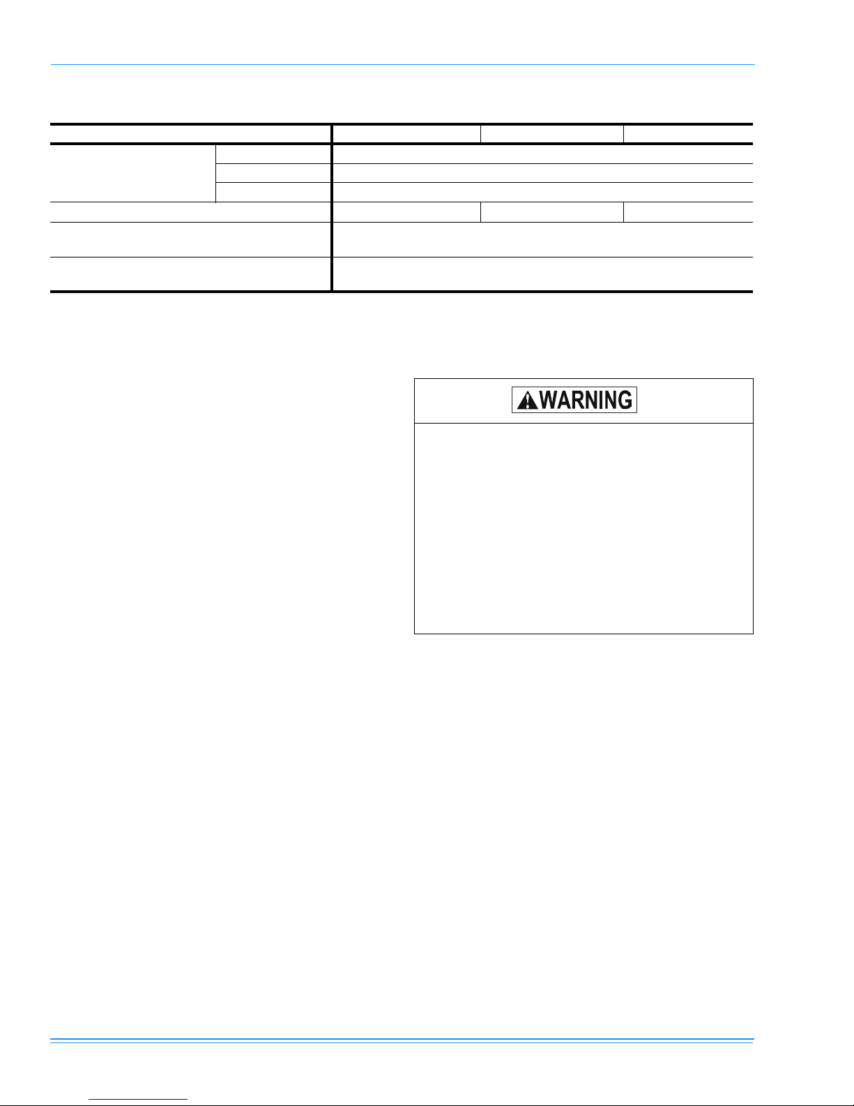
TABLE 1: UNIT APPLICATION DATA
UNIT MODEL NUMBER DM180 DM240 DM300
Voltage Variation,
Min. / Max.
Supply Air CFM, Min. / Max. 4,500 / 7,200 6,000 / 9,400 7,500 / 12,500
Wet Bulb Temperature (ºF) of Air on
Evaporator Coil, Min. / Max.
Dry Bulb Temperature (ºF) of Air on
Condenser Coil, Min. / Max.
1.
Utilization range “A” in accordance with ARI Standard 110.
1
208/230-3-60 187 / 253
460-3-60 414 / 506
575-3-60 518 / 630
LOCATION
Use the following guidelines to select a suitable location for these units.
284806-YIM-A-0107
57 / 72
0 / 120
1. Unit is designed for outdoor installation only.
2. Condenser coils must have an unlimited supply of
air.
3. Where a choice of location is possible, position the
unit on either north or east side of building.
4. For ground level installation, use a level concrete
slab with a minimum thickness of 4 inches. The
length and width should be at least 6 inches
greater than the unit base rails. Do not tie slab to
the building foundation.
5. Roof structures must be able to support the weight
of the unit and its options and/or accessories. Unit
must be installed on a solid level roof curb or
appropriate angle iron frame.
6. Maintain level tolerance to 1/2 inch maximum
across the entire length or width of the unit.
Excessive exposure of this furnace to contaminated combustion air may result in equipment
damage or personal injury. Typical contaminates include: permanent wave solutions, chlorinated waxes and cleaners, chlorine based
swimming pool chemicals, water softening
chemicals, carbon tetrachloride , Halogen type
refrigerants, cleaning solvents (e.g. perchloroethylene), printing inks, paint removers, varnishes, hydrochloric acid, cements and glues,
antistatic fabric softeners for clothes dryers,
masonry acid washing materials.
If a unit is to be installed on a roof curb or special frame
other than a YORK roof curb, gasketing must be
applied to all surfaces that come in contact with the unit
underside.
8 Unitary Products Group
Page 9
284806-YIM-A-0107
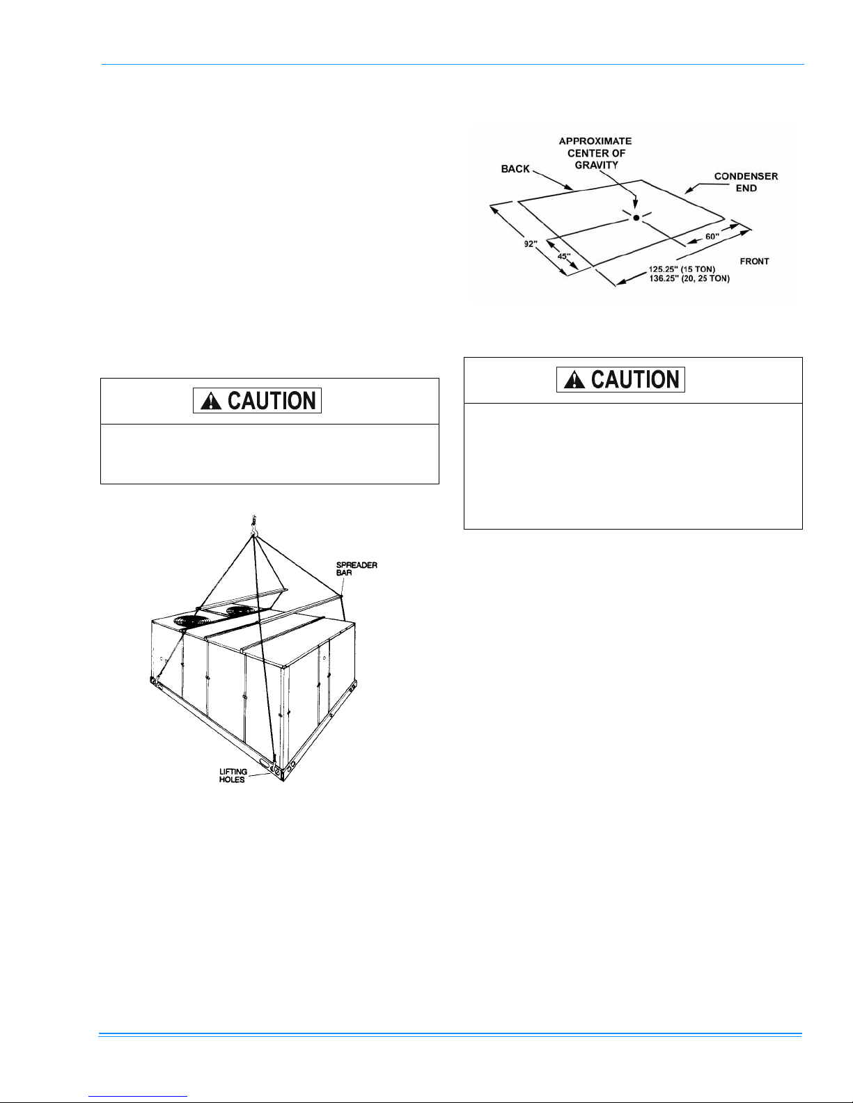
RIGGING AND HANDLING
Exercise care when moving the unit. Do not remove
any packaging until the unit is near the place of installation. Rig the unit by attaching chain or cable slings to
the round lifting holes provided in the base rails.
Spreaders, whose length exceeds the largest dimension across the unit, MUST BE USED. Refer to
Figure 1.
Units may also be moved or lifted with a forklift, from
the side only, providing that an accessory skid is us ed.
LENGTH OF FORKS MUST BE A MINIMUM OF 90".
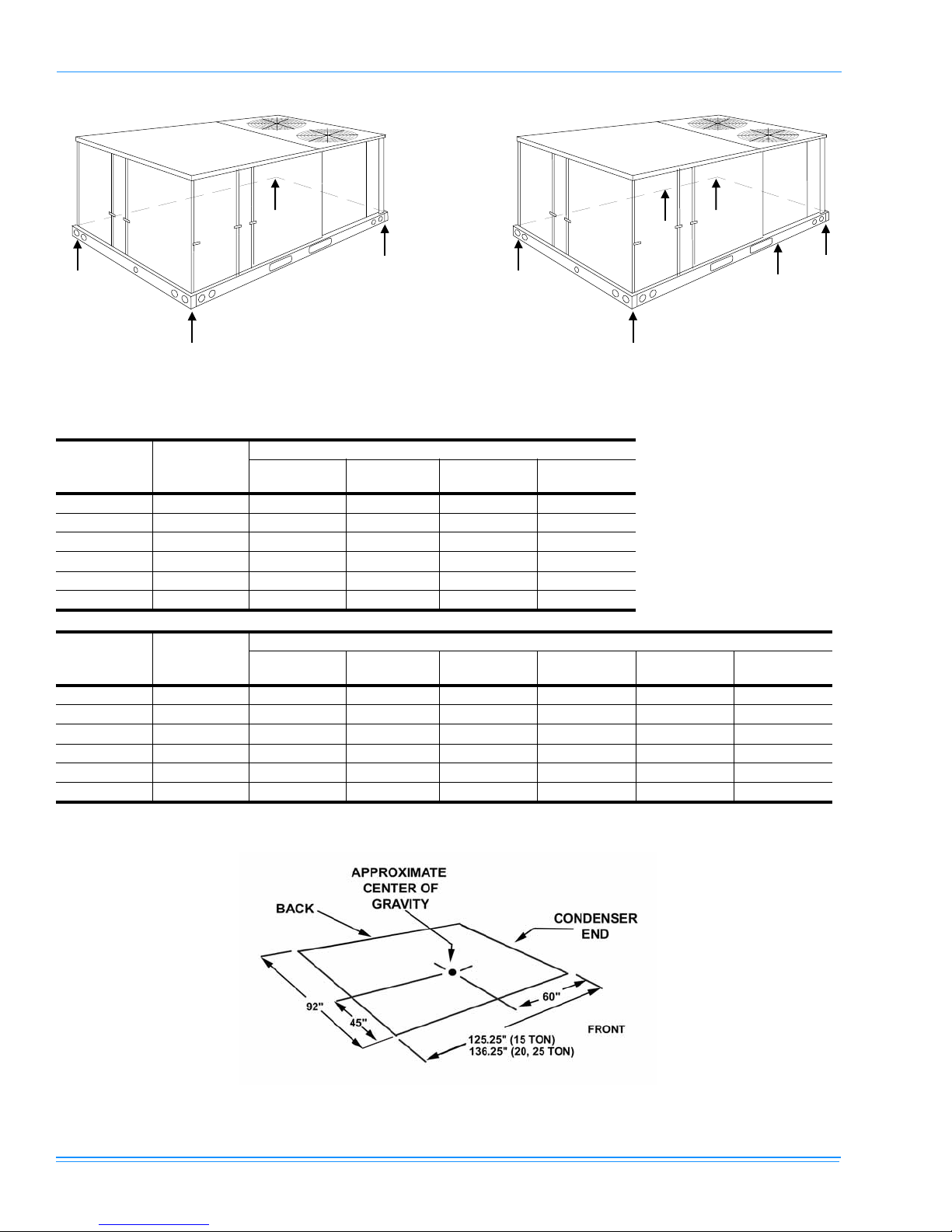
Refer to the Physical Data Table 7 for unit weights and
to the Figures 2 or 12 for approximate center of gravity.
Before lifting a unit, make sure that all panels
are in place and that its weight is distributed
equally on all cables so it will lift evenly.
FIGURE 2 - CENTER OF GRAVITY
An adhesive backed label is provided over the
outside of the combustion air inlet opening to
prevent moisture from entering the unit, which
could cause damage to electrical components.
Allow this closure label to remain in place until
the combustion air hood is to be installed (refer
to Vent and Combustion Hood Figure 8).
FIGURE 1 - TYPICAL RIGGING
CLEARANCES
All units require certain clearances for proper operation
and service. Installer must make provisions for adequate combustion and ventilation air in accordance
with Section 5.3, Air for Combustion and Ventilation of
the National Fuel Gas Code, ANSI Z223.1 (in U.S.A.)
or Sections 7.2, 7.3 or 7.4 of Gas Installation Codes
CSA-B149.1 (in Canada) and/or applicable provisions
of the local building codes. Refer to Figures 13, 14 and
15 for the dimensions and clearances required for combustible construction, servicing, and proper unit operation.
Unitary Products Group 9
Page 10
Do not permit overhanging structures or shrubs
to obstruct outdoor air discharge outlet, combustion air inlet or vent outlets.
DUCTWORK
Ductwork should be designed and sized according to
the methods in Manual Q of the A ir Conditioning Contractors of America (ACCA).
A closed return duct system shall be used. This shall
not preclude use of economizers or outdoor fresh air
intake. The supply and return air duct connections at
the unit should be made with flexible joints to minimize
noise.
The supply and return air duct systems should be
designed for the CFM and static requirements of the
job. They should NOT be sized to match the dimensions of the duct connections on the unit.
When fastening ductwork to side duct flanges
on unit, insert screws through duct flanges
only. DO NOT insert screws through casing.
Outdoor ductwork must be insulated and
waterproofed.
Refer to Figures 13 and 14 for information concerning
side and bottom supply and return air duct opening
dimensions.
284806-YIM-A-0107
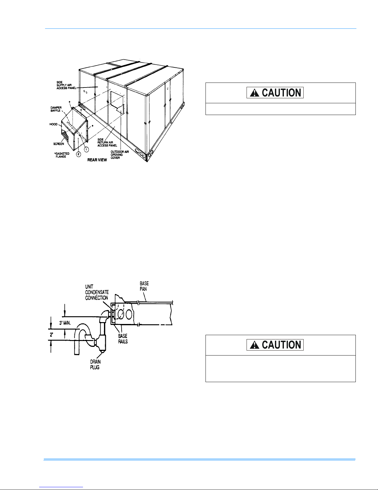
FIXED OUTDOOR AIR INTAKE DAMPER
This damper is shipped inside the return air compartment. It is completely assembled and ready for installation. A damper baffle inside of the hood is adjustable to
provide variable amounts of outdoor air intake on units
that are not provided with an economizer or a motorized damper option. Refer to the Fixed Outdoor
Damper Figure 3.
Gasketing and mounting screws are provided in a parts
bag attached to the hood assembly. Apply gasketing to
the three flange surfaces on the hood prior to installing
the hood. Extend gasketing 1/4 inch beyond the top
and bottom of the two side flanges to insure adequate
sealing.
Adjusting the damper to the desired air flow may be
done before mounting the hood into position or after
installation by removing the front hood panel or the
screen on the bottom of the hood. Damper baffle in
position 1 will allow approximately 10% outdoor air
flow, position 2 approximately 15% and, to allow
approximately 25%, remove the damper baffle.
On units with bottom return air application install the
damper assembly over the opening in the side return
air access panel. Remove and discard the opening
cover and the covering over the hood mounting holes
(used for shipping) before installing. Secure with the
screws provided.
On units with side return air applications, install the
damper assembly on the return air ductwork as close
to the unit as possible. Cut an opening 16 inches high
by 18 inches wide in the ductwork to accom m o da te the
damper. Using the holes in the hood flanges as a template, drill 9/64 inch dia. (#26 drill) holes into the ductwork and secure with the screws provided.
NOTE: It is recommended that, in Canada, the outlet
duct be provided with a removable access
panel. It is recommended that this opening be
accessible when the unit is installed in service,
and of a size such that smoke or reflected light
may be observed inside the casing to indica te
the presence of leaks in the heat exchanger.
The cover should be attached in a manner
adequate to prevent leakage.
10 Unitary Products Group
If outdoor air intake will not be required on
units with bottom return air applications, the
damper assembly should still be mounted on
the side return air access panel, per the
instructions above, to insure moisture is not
drawn into the unit during operation. The covering over the mounting holes only need be
removed. Do not remove the opening cover.
Page 11
284806-YIM-A-0107
FIGURE 3 - FIXED OUTDOOR AIR DAMPER
CONDENSATE DRAIN
Plumbing must conform to local codes. Use a sealing
compound on male pipe threads. Install a condensate
drain line from the one-inch NPT female connection on
the unit to an open drain.
NOTE: The condensate drain operates in a negative
pressure in the cabinet. The condensate drain
line MUST be trapped to provide proper drainage. See Figure 4.
COMPRESSORS
Units are shipped with compressor mountings factoryadjusted and ready for operation.
Do not loosen compressor mounting bolts.
FILTERS
Two-inch or four-inch filters can be supplied with each
unit. Filters must always be installed ahead of the
evaporator coil and must be kept clean or replaced with
same size and type. Dirty filters will reduce the capacity
of the unit and will result in frosted coils or safety shutdown. Minimum filter area and required sizes are
shown in Physical Data Table 7.
SERVICE ACCESS
The following removable panels provide access to all
serviceable components:
• Compressor compartment
• Electric Heat compartment
• Gas Heat compartment (Two panels)
• Side Supply & Return Air compartments
(Two panels)
• Blower compartment (Three panels)
• Main control box
• Filter compartment
• Outdoor Air compartment (Two panels)
FIGURE 4 - RECOMMENDED DRAIN PIPING
Unitary Products Group 11
Refer to Figures 13 and 14 for location of these access
panels.
Make sure that all screws and panel latches
are replaced and properly positioned on the
unit to maintain an airtight seal.
Page 12

284806-YIM-A-0107
2
THERMOSTAT
TERMINALS
1
ElectronicprogrammableThermostat2ET0770010024(includessubbase).
TerminalsA1andA2providearelayoutput toclosetheoutdoor
economizerdamperswhenthethermostatswitchestotheset-backposition
1
RC
RH
Y1
Y2
W1
W2
G
C
X1
X3
X4
A1
A2
T
T
TOREMOTESENSOR
2ET04701324IFUSED
UNIT CONTROL
BOARD
R
Y1
Y2
W1
W2
G
C
X
2
OCC
24Volt
Transformer
T - S T A T
W 1
W 2
Y 1
G
Y 2
C
R H
R C
W 1
W 2
Y 1
G
O C C
M I N P O S
Y 2
X
R
S D
C
.
R E M O T E
U N I T C O N T R O L
B O A R D
FIGURE 5 - TYPICAL FIELD WIRING
12 Unitary Products Group
Page 13

284806-YIM-A-0107
THERMOSTAT
The room thermostat should be located on an inside
wall approximately 56 inches above the floor where it
will not be subject to drafts, sun exposure or heat from
electrical fixtures or appliances. Follow manufacturer's
instructions enclosed with thermostat for general installation procedure. A minimum of seven color-coded
insulated wires (#18 AWG) should be used to connect
thermostat to unit.
SPACE SENSOR
The space sensor, if used, should be located on an
inside wall approximately 56 inches above the floor
where it will not be subject to drafts, sun exposure or
heat from electrical fixtures or appliances. Follow manufacturer's instructions enclosed with sensor for general installation procedure.
POWER AND CONTROL WIRING
Field wiring to the unit must conform to provisions of
the National Electrical Code, ANSI / NFPA No. 70 (in
U.S.A.), current Canadian Electrical Code C22.1 (in
Canada) and/or local ordinances. The unit must be
electrically grounded in accordance with NEC and CEC
(as specified above) and/or local codes. Voltage tolerances, which must be maintained at the compressor
terminals, during starting and running conditions, are
indicated on the unit Rating Plate and the Unit Application Data table.
The internal wiring harness furnished with this unit is
an integral part of a CSA design certified unit. Field
alteration to comply with electrical codes should not be
required.
type shown on the wiring diagram and the same minimum gauge as the replaced wire.
Electrical line must be sized properly to carry the load.
Use copper conductors only. Each unit must be wired
with a separate branch circuit fed directly from the
meter panel and properly fused.
When connecting electrical power and control
wiring to the unit, waterproof type connectors
MUST BE USED so that water or moisture
cannot be drawn into the unit during normal
operation. The above waterproofing conditions
will also apply when installing a field-supplied
disconnect switch.
Refer to the Typical Field Wiring Figure 5 and to the
appropriate unit wiring diagram for control circuit and
power wiring information.
TABLE 2: CONTROL WIRE SIZES
Wire Size
18 AWG 150 Feet
1.
From the unit to the thermostat and back to the unit.
Maximum Length
1
OPTIONAL ELECTRIC HEAT
The factory-installed heaters are wired for single point
power supply. Power supply need only be brought into
the single point terminal block and thermostat wiring to
the low voltage terminal strip located in the upper portion of the unit control box.
A fused disconnect switch should be field provided for
the unit. The switch must be separate from all other circuits. Wire entry at knockout openings require conduit
fittings to comply with NEC (in U.S.A.), CEC (in Canada) and/or local codes. Refer to Figure 13 for installation location. If any of the wire supplied with the unit
must be replaced, replacement wire must be of the
Unitary Products Group 13
These CSA approved heaters are located within the
central compartment of the unit with the heater elements extending into the supply air chamber. Refer to
Figure 13 for access panel location.
Fuses are supplied, where required, by the factory.
Some KW sizes require fuses and others do not. Refer
to Table 3 for minimum CFM limitations and to Tables 9
and 12 for electrical data.
Page 14

TABLE 3: ELECTRIC HEAT APPLICATION DATA
NOMINAL
HEATER SIZE
(KW)
18 208/230,460,575 4500
36 208/230,460,575 4500
54
72
VOLTAGE
3-PHASE,
60 HZ
208/230 5000
460,575 4500
208/230 5000
460,575 4500
OPTIONAL GAS HEAT
284806-YIM-A-0107
MINIMUM CFM UNIT SIZE
15 TON 20 TON 25 TON
6000 7500
These gas-fired heaters have aluminized-steel or
optional stainless steel, tubular heat exchangers with
spark ignition with proven pilot.
All gas heaters are shipped from the factory equipped
for natural gas use, but can be field converted to L.P./
Propane with Kit Model # 1NP0418. See Gas Heat
Application Data Table.
TABLE 4: GAS HEAT APPLICATION DATA
0 To
2,000 Feet
Above
Sea Level
Max. Min. Max. Min. Max. Max. Min. Max.
300 150 270 135 240 213 15, 20 & 25 Ton 279 20 50
400 200 360 180 320 281 15, 20 & 25 Ton 372 30 60
1.
On VAV units, individual VAV boxes must be full open in heating mode to insure airflow falls within
temperature rise range.
2,000 To
4,500 Feet
Above
Sea Level
GAS PIPING
Proper sizing of gas piping depends on the cubic feet
per hour of gas flow required, specific gravity of the gas
and the length of run. "National Fuel Gas Code" Z223.1
(in U.S.A.) or the current Gas Installation Codes CSAB149.1 (in Canada) should be followed in all cases
unless superseded by local codes or gas utility requirements. Refer to the Pipe Sizing Table 5.
The heating value of the gas may differ with locality.
The value should be checked with the local gas utility.
NOTE: There may be a local gas utility requirement
specifying a minimum diameter for gas piping.
All units require a one-inch pipe connection at
the entrance fitting.
Output Capacity (Mbh)
0 To
2,000 Feet
Above
Sea Level
2,000 To
4,500 Feet
Above
Sea Level
Available
on Models
Gas
Rate
(Ft./Hr.)
TABLE 5: PIPE SIZING
Length in Feet
10 520 1,050
20 350 730
30 285 590
40 245 500
50 215 440
60 195 400
70 180 370
80 170 350
90 160 320
100 150 305
Maximum capacity of pipe in cubic feet of gas per hour. (Based upon
a pressure drop of 0.3 inch water column and 0.6 specific gravity
gas).
Nominal Iron Pipe Size
1 in. 1-1/4 in.
Temp.
Rise ºF
At
Full Input
1
14 Unitary Products Group
Page 15
284806-YIM-A-0107
GAS CONNECTION
The gas supply line can be routed through the knockouts located on the front of the unit or through the
opening provided in the unit's base. Refer to Figure 13
to locate these access openings. Typical supply piping
arrangements are shown in the figures on Page 16. All
shaded items are field-supplied.
If gas supply line is routed through the unit's base
ensure that the burner assembly can be removed for
maintenance without disturbing the supply line. The
supply piping and fittings must lie below the bottom gas
manifold to avoid interference with the burner assembly.
Two grommets are shipped in the blower compartment
(in parts bag taped to the blower housing) of every unit
with gas heat and should be used in the knockouts
when the gas piping penetrates the front of the unit.
After the gas supply piping has been installed, the bottom opening in the unit should be sealed to prevent
water from leaking into the building.
Gas piping recommendations
:
1. A drip leg and a ground joint union must be
installed in the gas piping.
2. When required by local codes, a manual shut-off
valve may have to be installed outside of the unit.
3. Use wrought iron or steel pipe for all g as lines. Pipe
compound should be applied sparingly to male
threads only.
4. All piping should be cleaned of dirt and scale by
hammering on the outside of the pipe and blowing
out the loose dirt and scale. Before initial start-up,
be sure that all of the gas lines external to the unit
have been purged of air.
5. The gas supply should be a separate line and
installed in accordance with all safety codes as
prescribed under "Limitations". After the gas connections have been completed, open the main
shut-off valve admitting normal gas pressure to the
mains. Check all joints for leaks with soap solution
or other material suitable for the purpose. NEVER
USE A FLAME.
FIRE OR EXPLOSION HAZARD
FAILURE TO FOLLOW THE SAFETY WARN-
ING EXACTLY COULD RESULT IN SERIOUS
INJURY, DEATH OR PROPERTY DAMAGE.
NEVER TEST FOR GAS LEAKS WITH AN
OPEN FLAME. USE A COMMERICALLY
AVAILABLE SOAP SOLUTION MADE SPECIFICALLY FOR THE DETECTION OF
LEAKS TO CHECK ALL CONNECTIONS. A
FIRE OR EXPLOSION MAY RESULT CAUSING PROPERTY DAMAGE, PERSONAL
INJURY OR LOSS OF LIFE.
6. The furnace and its individual manual shut-off
valve must be disconnected from the gas supply
piping system during any pressure testing of that
system at test pressures in excess of 1/2 psig
(3.48kPa).
Natural gas may contain some propane. Propane, being an excellent solvent, will quickly
dissolve white lead or most standard commercial compounds. Therefore, a special pipe
compound must be applied when wrought iron
or steel pipe is used. Shellac base compounds
such as Gaskolac or Stalastic, and compounds
such as Rectorseal #5, Clyde's or John Crane
may be used.
Unitary Products Group 15
The furnace must be isolated from the gas supply
piping system by closing its individual manual shutoff valve during any pressure testing of the gas
supply piping system at test pressures equal to or
less than 1/2 psig (3.48kPa).
7. A 1/8 inch NPT plugged tap, accessible for test
gage connection, must be installed immediately
upstream of the gas supply connection to the furnace.
Page 16
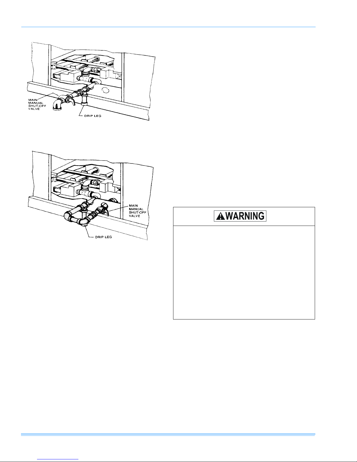
FIGURE 6 - EXTERNAL SUPPLY CONNECTION
EXTERNAL SHUT-OFF
284806-YIM-A-0107
2. The proper p ressure regu lation. (Two-stage regulation is recommended from the standpoint of both
cost and efficiency.)
3. The pressure drop in the lines between regulators
and between the second stage regulator and the
appliance. Pipe size required will depend on the
length of the pipe run and the total load of all appliances.
Complete information regarding tank sizing for vaporization, recommended regulator settings, and pipe sizing is available from most regulator manufacturers and
L.P./propane gas suppliers.
L.P./propane gas is an excellent solvent and special
pipe compound must be used when assembling piping
for this gas as it will quickly dissolve white lead or most
standard commercial compounds. Shellac base compounds such as Rectorseal #5 are satisfactory for this
type of gas.
Check all connections for leaks when piping is completed, using a soap solution. NEVER USE A FLAME.
FIGURE 7 - BOTTOM SUPPLY CONNECTION
EXTERNAL SHUT-OFF
L.P. UNITS, TANKS AND PIPING
All gas heat units are shipped from the factory
equipped for natural gas use only. The unit may be
converted in the field for use with L.P./propane gas
with accessory kit model number 1NP0418.
All L.P./propane gas equipment must conform to the
safety standards of the National Fire Protection Association.
For satisfactory operation, L.P./propane gas pressure
must be 10.0 I.W.C. at the unit manifold under full load.
Maintaining proper gas pressure depends on three
main factors:
1. The vaporization rate depends on (a) the temperature of the liquid and (b) the "wetted surface" ar ea
of the container or containers.
FIRE OR EXPLOSION HAZARD
FAILURE TO FOLLOW THE SAFETY WARN-
ING EXACTLY COULD RESULT IN SERIOUS
INJURY, DEATH OR PROPERTY DAMAGE.
NEVER TEST FOR GAS LEAKS WITH AN
OPEN FLAME. USE A COMMERICALLY
AVAILABLE SOAP SOLUTION MADE SPECIFICALLY FOR THE DETECTION OF
LEAKS TO CHECK ALL CONNECTIONS. A
FIRE OR EXPLOSION MAY RESULT CAUSING PROPERTY DAMAGE, PERSONAL
INJURY OR LOSS OF LIFE.
VENT AND COMBUSTION AIR HOODS
Two vent hoods and a combustion air hood (with
screens) are shipped attached to the blower housing in
the blower compartment. These hoods must be
installed to assure proper unit function. All hoods must
be fastened to the outside of the gas heat access panel
with the screws provided in the bag also attached to
the blower housing.
16 Unitary Products Group
Page 17
284806-YIM-A-0107
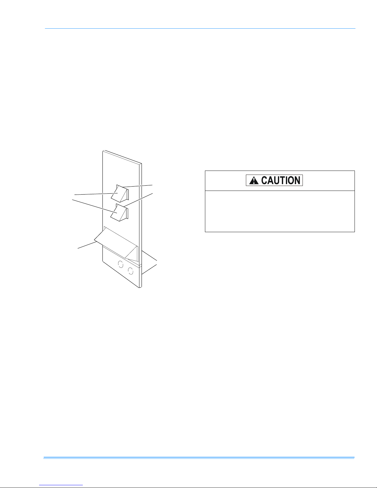
A
The screen for the combustion air intake hood is
secured to the inside of the access panel opening with
four fasteners and the screws used for mounting the
hood to the panel. The top flange of this hood slips in
under the top of the access panel opening when installing. Refer to Vent and Combustion Air Hood Figure 8.
Each vent hood is installed by inserting the top flange
of the hood into the slotted opening in the access panel
and securing in place.
The products of combustion are discharged horizontally through these two screened, hooded vent openings on the upper gas heat access panel.
SLOTTED
VENT AIR
OUTLET
HOODS
OPENINGS IN
ACCESS PANEL
OPTIONAL POWER EXHAUST/BAROMETRIC RELIEF
DAMPER RAIN HOOD
The instructions for the power exhaust/barometric relief
damper rain hood can be found in the kit. The exhaust
fan, all supporting brackets, angles, and the wiring are
factory installed as part of the power exhaust option.
OPTIONAL ECONOMIZER AND POWER EXHAUST
DAMPER SET POINT ADJUSTMENTS AND INFORMATION
Remove the economizer access panel from the unit.
Loosen but do not remove the two panel latches.
Locate the economizer control module, where the following adjustments will be made.
EXTREME CARE MUST BE EXCERCISED IN
TURNING ALL SETPOINT, MAXIMIUM, AND
MINIMUM DAMPER POSITIONING ADJUSTMENT SCREWS TO PREVENT TWISTING
THEM OFF.
COMBUSTION
IR INTAKE
HOOD
GAS HEAT
ACCESS
PANELS
FIGURE 8 - VENT AND COMBUSTION AIR HOOD
OPTIONAL ECONOMIZER/MOTORIZED DAMPER RAIN
HOOD
The instruction for the optional economizer/motorized
damper rain hood can be found in the kit. Use these
instructions when field assembling an economizer rain
hood onto a unit. The outdoor and return air dampers,
the damper actuator, the damper linkage, the outdoor
and return air divider baffles, and all the control sensors are factory mounted as part of the "Factory
installed" economizer option.
Check that the damper blades move smoothly without
binding; carefully turn the Minimum Position Adjusting
screw (found on the damper control module) fully
clockwise and then set the thermostat indoor fan switch
to the on position and then off, or energize and deenergize terminals "R" to "G".
MINIMUM POSITION ADJUSTMENT
With thermostat set to indoor fan on position, or terminals "R" to "G" energized, turn the Minimum Position
Adjusting screw (located on the damper control module) counterclockwise until the desired minimum
damper position has been attained.
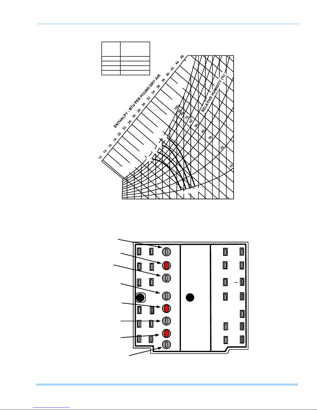
ENTHALPY SET POINT ADJUSTMENT
The enthalpy set point may now be set by selecting the
desired setpoint shown in the Enthalpy Setpoint Ad justment Figure 9. Adjust as follows:
Unitary Products Group 17
Page 18
284806-YIM-A-0107
• For a single enthalpy operation carefully turn the
set point adjusting screw (found on the damper
control module) to the "A", "B", "C" or "D" setting
corresponding to the lettered curve of the Enthalpy
Setpoint Adjustment Figure 9.
• For a dual enthalpy operation, carefully turn the set
point adjusting screw fully clockwise past the "D"
setting.
POWER EXHAUST DAMPER SETPOINT (WITH OR WITHOUT POWER EXHAUST)
• With no power exhaust option, adjust the Exha u st
Air Adjustment Screw fully clockwise. This will
allow 2nd stage cooling to operate.
• With power exhaust option, each building pressurization requirement will be different. The point at
which the power exhaust comes on is determined
by the economizer damper position (Percent
Open). The Exhaust Air Adjustment Screw should
be set at the Percent Open of the economizer
damper at which the power exhaust is needed. It
can be set from 0 to 100% damper open.
INDOOR AIR QUALITY AQ
Indoor Air quality (indoor sensor input): Terminal AQ
accepts a +2 to +10 Vdc signal with respect to the
(AQ1) terminal. When the signal is below it's setpoint,
the actuator is allowed to modulate normally in accordance with the enthalpy and mixed air sensor inputs.
When the AQ signal exceeds it's setpoint setting and
there is no call for free cooling, the ac tuator is proportionately modulated from the 2 to 10 Vdc signal, with 2
Vdc corresponding to full closed and 10 Vdc corresponding to full open. When there is no call for free
cooling, the damper position is limited by the IAQ Max
damper position setting. When the signal exceeds it's
setpoint (Demand Control Ventilation Setpoint) setting
and there is a call for free cooling, the actuator modulates from the minimum position to the full open position based on the highest call from either the mixed air
sensor input or the AQ voltage input.
• Optional CO
Space Sensor Kit Part #
2
2AQ04700324
• Optional CO
Unit Sensor Kit Part # 2AQ04700424
2
Replace the economizer access panel.
pressure transducer is used to monitor supply duct
static pressure and return a speed reference signal to
the VFD to control the output of the indoor blower
motor.
DUCT STATIC PRESSURE TRANSDUCER
A 0-5" WC pressure transducer, located in the control
box compartment, is used to sense static (gauge) pre ssure in the supply air duct and convert this pressure
measurement to a proportional 0-5 VDC electrical output.
Pressure-transmitting plastic tubing (1/4" diameter)
must be field supplied and installed from the transducer
to both the ductwork and to the atmosphere. Connect
the tubing from the 'HIGH' pressure tap of the transducer to a static pressure tap (field supplied) in the
supply duct located at a point wh ere con stant p ressure
is expected. To prevent an unstable signal due to air
turbulence, there should be no obstructions, turns or
VAV terminal boxes up- or down-stream of the sensing
tube location for at least a distance of 6-10 times the
duct diameter. Tubing must also be run between the
'LOW' pressure tap of the transducer and atmospheric
pressure (outside of the unit).
Do not run plastic tubing in the supply or return
air ducts as air movement could cause erroneous pressure measurements. If the tubing penetrates through the bottom of the unit be sure
openings are sealed to prevent air and water
leakage.
VAV CONTROL BOARD
A VAV control board, located in the top-left corner of
the control box, is used to convert the pressure transducer input signal into a speed reference signal that
the drive uses to control the speed of the blower moto r.
This modulating speed reference signal is generated
using an internal Proportional-Integral (PI) control loop
which continuously calculates an output value.
A brief description of the VAV board's I/O terminals that
are used follows;
OPTIONAL VARIABLE AIR VOLUME (VAV)
A variable air volume (VAV) option using a variable frequency drive (VFD) is available for applic ations requiring a constant supply duct static pressure. A differential
18 Unitary Products Group
• DUCT PRES - a 0-5 VDC analog input received
from the duct static pressure transducer.
• FAN - a 2-10 VDC analog output sent to the VFD to
control the speed of the indoor blower motor.
Page 19
284806-YIM-A-0107
• VAV BOX (gas/electric heat only) - a binary output
used to drive the building's VAV boxes to full-open
during heating operation.
Programmable set points
:
The duct static set point is the pressure that the drive
will maintain when operating the unit in VAV mode. The
set-point is adjustable between 0" W C and 5" WC with
the default setting of 1.5" WC.
The duct static high-limit set point is the maximum
allowable duct pressure to prevent damage from overpressurization of the ductwork in the event of either a
drive or damper failure. The high-limit set-point is
adjustable between 0" WC and 5" WC with the factory
default setting of 4.5" WC. If the duct static pressure
reaches the high-limit set point, then the supply fan
motor will be shutdown.
NOTE: Either of the set points described above can be
changed through the unit control board (UCB)
with the use of a USB-to-RS485 converter,
personal computer or PDA and a down-loaded
copy of the Simplicity PC software available at
www.yorkupg.com.
must be field wired to the building's VAV boxes to
ensure a fully open damper during heating operation.
MANUAL BYPASS
An optional, factory-installed manual bypass switch
available with factory-installed VFD can be found in the
Blower Motor Access compartment and has the following three positions:
• DRIVE - routes power through the VFD for modulating control of the indoor blower motor.
• LINE (or BYPASS) - routes power directly to the
motor which provides full-speed motor operation
and complete electrical isolation of the drive.
• TEST - routes power to the VFD but not to the
motor to allow for drive programming and/or diagnostics.
If a drive failure occurs, the unit does not automatically
switch to bypass mode. The LINE/DRIVE/TEST switch
must be manually switched to the LINE (BYPASS)
position. If there is a call for the fan, the indoor blower
motor will run at full-speed while in the bypass mode.
The customer must be aware of the duct pressure design limit, and what the duct pressure
sensor is reading when the peak pressure is
reached (ie the pressure transducer sensing
tube may not be located at the place of highest
pressure in the system).
FACTORY-INSTALLED VFD
The factory-installed VFD is mounted in the Blower
Access Compartment above the blower assembly. The
drive comes wired from the factory to include both 3phase power and control connections (run permit signal, speed reference signal & fault signal).
All required drive parameters are pre-programmed at
the factory, except in the case of 208-volt applications,
where Parameter 50.16 (which defines motor nameplate voltage) must be changed to a value of 208.00.
See the enclosed drive user manual for instruction on
changing parameter settings.
For units also equipped with gas/electric heat, a normally-open, SPST relay located in the unit control box
If the unit is operated with the manual bypass
switch in the LINE (BYPASS) position and
there are VAV boxes present in the duct system, then boxes must be driven to the full-open
position using a customer-supplied power
source to prevent over-pressur izing and possible damage to the ductwork.
Before beginning any service, disconnect all
power to the drive. Be aware that high voltages
are present in the drive even after power has
been disconnected. Capacitors within the drive
must be allowed to discharge before beginning
service.
BAS-READY VFD
Factory-installed VFD is also available with 'BASready' models. Terminal blocks are provided in the control box (in place of the VAV control board) for field wiring of a customer-installed BAS to receive 24 VAC
power and to connect to the following control signals:
Unitary Products Group 19
Page 20
284806-YIM-A-0107
• a duct static pressure transducer input signal (0-5
VDC)
• an economizer actuator input signal (2-10 VDC)
• an economizer actuator output signal (2-10 VDC)
• a VFD speed reference output signal (2-10 VDC)
The use of shielded cable is recommended for the
above control wiring connections.
NOTE: Factory-installed VFD is not available with fac-
tory-installed BAS options due to space limitations in the control box.
A solid-state, lock-out relay (LR) and 100-
μF, 50 VDC
capacitor must be field-supplied and installed to provide a means to transmit a potential fault signal back to
the BAS controller. The specific relay part number
required will depend upon the need for either AC-output or DC-output. See price pages for fur th er det ails .
Once the appropriate relay an d ca pacito r ar e ob taine d,
install the capacitor across LR terminals '3' & '4' and
make the following wiring connections:
• LR '1' to BAS controller
• LR '2' to BAS controller
• LR '3' to UCB 'X'
• LR '4' to UCB 'C'
'VFD-READY' FOR CUSTOMER-INSTALLATION
Units configured as 'VFD-ready' provide provisions for
a customer-installed drive. The physical dimensions of
VFDs can vary greatly among manufacturers, horsepower ratings and voltage requirements. Keep in mind
that drive manufacturers also require various minimum
clearances to allow for adequate internal cooling of the
drive during operation.
The unit comes with a mounting bracket installed in the
Blower Access compartment which may accommodate
other vendor's drives depending on their size. In order
to utilize the unit's mounting bracket, the maximum recommended drive dimensions are as follows:
If the drive will not fit in the allotted space, then it will
have to be mounted within a NEMA-4 enclosure for
outside installation or elsewhere within the building on
a perpendicular wall which is not subjec ted to excessive temperature, vibration, humidity, dust, corrosive
gas, explosive gas, etc.
The power leads to the drive (L1, L2, L3) and from the
motor (T1, T2, T3) along with the respective ground
wires are supplied with the unit and need to be connected after the drive is installed.
Do not connect AC power to the T1, T2, T3
drive terminals to prevent damage to the VFD.
A terminal block located in the control box is provided
for field connection of the VFD speed reference signal
(2-10 VDC) and to the normally-open, run-permit auxiliary contact. The use of shielded cable is recommended for the above control wiring connections.
For VFD-ready units also equipped with gas/electric
heat, a normally-open, SPST relay located in the unit
control box must be wired to the building's VAV boxes
to ensure fully open dampers during heating operation.
OPTIONAL HOT GAS BYPASS (HGBP)
To allow for low cooling load operation, a direct-acting,
pressure-modulating bypass control valve installed on
the system #1 discharge line is used to divert high temperature, high pressure refrigerant around the TXV in
order to maintain a desired minimum evaporator pressure.
The opening pressure of the bypass valve is fully
adjustable between 0 and 80 psig with a factory-setting
of 60 psig. HGBP is standard on all units with VAV and
optional with CV units.
For 5-hp motor applications....................... 10" H x 6" W x 7" D
For 7.5 thru 15-hp motor applications........13" H x 8" W x 8" D
20 Unitary Products Group
Page 21
284806-YIM-A-0107
40
(4)
70
(21)
50
(10)
55
(13)
60
(16)
65
(18)
35
(2)
45
(7)
75
(24)
80
(27)
35
(2)
40
(4)45(7)
50
(10)55(13)
60
(16)
65
(18)
70
(21)
75
(24)80(27)
85
(29)
85
(29)
90
(32)
90
(32)
105
(41)
110
(43)
100
(38)
95
(35)
95
(35)
100
(38)
105
(41)
110
(43)
APPROXIMATE DRY BULB TEMPERATURE - 0F (0C)
D
D
C
C
B
B
A
A
CONTROL
CURVE
CONTROL POINT
APPROX.
0
F (0C)
AT 50% RH
A
D
C
B
63 (17)
73 (23)
70 (21)
67 (19)
FIGURE 9 - ENTHALPY SETPOINT ADJUSTMENT
Exhaust Air
Adjustment
Screw
Exhaust Air LED
Damper Min.
Position
Screw
Indoor Air Quality
Max. Adjustment
Screw
Indoor Air Quality
LED
Indoor Air Quality
Min. Adjustment
Screw
Free Cooling LED
Economizer Enthalpy
Set Point Adjustment
Screw
N1
P1
T1
AQ1 AQ
SO+ SO
SR+
FIGURE 10 - HONEYWELL ECONOMIZER CONTROL W7212
N
P
EXH
Set
EXH
Min
Pos
T
IAQ
Max
IAQ
IAQ
Min
Free
SR
Cool
BC
A
D
TR TR1
24
Vac
HOT
+
1
3
EF EF1
24
Vac
COM
2
5
4
Unitary Products Group 21
Page 22
284806-YIM-A-0107
B
C
A
D
FRONT
A
F
B
E
FRONT
FIGURE 11 - FOUR AND SIX POINT LOADS
TABLE 6: FOUR AND SIX POINT LOADS
Total
Unit Size
Shipping
Weight
ABC D
180 Gas 2300 539 563 612 586
240 Gas 2500 538 563 715 684
300 Gas 2531 593 645 674 619
180 Elec 2100 492 514 558 536
240 Elec 2300 295 517 658 630
300 Elec 2331 546 594 621 570
Total
Unit Size
Shipping
Weight
ABC D E F
180 Gas 2300 351 367 392 416 399 375
240 Gas 2500 334 350 426 502 481 407
300 Gas 2531 390 412 436 456 430 407
180 Elec 2100 320 335 358 380 364 343
240 Elec 2300 307 322 392 462 442 375
300 Elec 2331 359 379 402 420 396 375
4 Point Loads (lbs)
6 Point Loads (lbs)
D
C
FIGURE 12 - CENTER OF GRAVITY
22 Unitary Products Group
Page 23
284806-YIM-A-0107
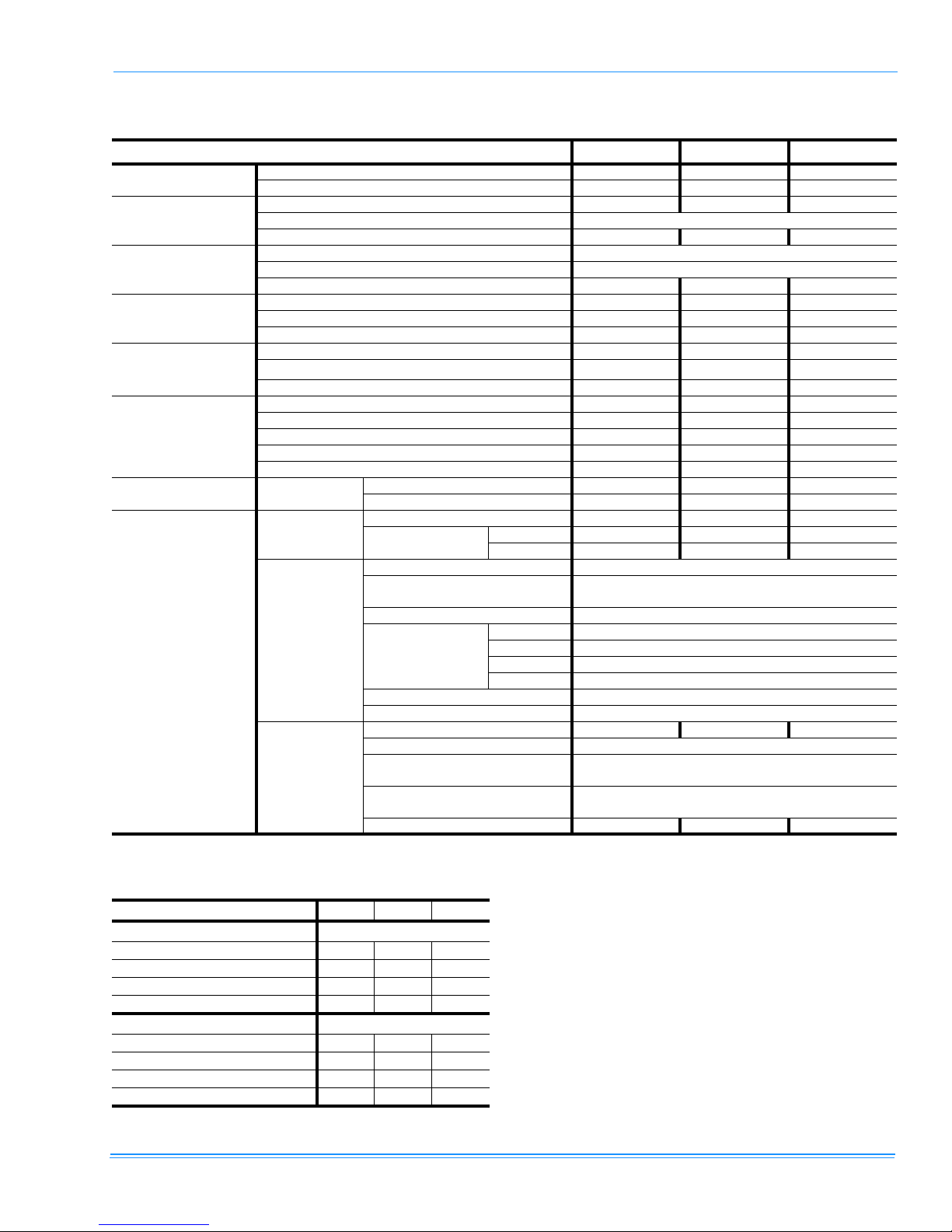
TABLE 7: PHYSICAL DATA
EVAPORATOR
BLOWER
EVAPORATOR COIL
CONDENSER FAN
(Two Per Unit)
CONDENSER
COIL
COMPRESSOR
(Qty. Per Unit)
FILTERS
CHARGE
OPERATING
WEIGHTS
(LBS.)
1.
This compressor will be energized first.
CENTRIFUGAL BLOWER (Dia. x Wd.) 15x15 18x15 18x15
FAN MOTOR HP, STANDARD/HI STATIC 5.0 7.5 10/15
ROWS DEEP 3 3 4
FINS PER INCH 13.5
FACE AREA (Sq. Ft.) 15.5 20 20.52
PROPELLER DIA. (In.) (Each) 30
FAN MOTOR HP (Each) 1
NOM. CFM TOTAL (Each) 6,500 7,200 7,200
ROWS DEEP 2 2 2
FINS PER INCH 13 20 20
FACE AREA (Sq. Ft.) 36 43.3 43.3
5 TON HERMETIC (RECIP.) 1 - -
10 TON TANDEM (RECIP.)
12.5 TON (SCROLL) - - 2
QUANTITY PER UNIT (12" X 24" X 2" or 4”) - - QUANTITY PER UNIT (16" X 20" X 2" or 4”) - 4 4
QUANTITY PER UNIT (16" X 25" X 2" or 4”) - 4 4
QUANTITY PER UNIT (18" X 24" X 2" or 4”) 5 - TOTAL FACE AREA (Sq. Ft.) 15 20 24
REFRIGERANT
22 (Lb./Oz.)
BASIC UNIT
MODELS DM180 DM240 DM300
SYSTEM No.1 17/8 18/0 18/0
SYSTEM No. 2 8/8 18/0 18/0
COOLING ONLY 1900 2100 2291
GAS / ELECTRIC
ECONOMIZER 160
ECONOMIZER WITH
POWER EXHAUST
MOTORIZED DAMPER 150
OPTIONS
ELECTRIC HEATER
HOT GAS BYPASS 10
SUPPLY FAN VFD See Table 8
ROOF CURB 175 185 185
BAROMETRIC DAMPER 45
ECONOMIZER / MOTORIZED
DAMPER RAIN HOOD
ECONOMIZER / POWER
ACCESSORIES
EXHAUST RAIN HOOD
WOOD SKID 200 220 220
1
1
N24 2100 2300 2491
N32 2140 2340 2531
18 KW 25
36 KW 30
54 KW 35
72 KW 40
2-
245
55
90
TABLE 8: SUPPLY FAN VFD WEIGHTS, IN LBS.
SUPPLY FAN MOTOR 230V 460V 575V
W/O MANUAL BYPASS
5.0 hp
7.5 hp
10.0 hp
15.0 hp
W/MANUAL BYPASS
5.0 hp
7.5 hp
10.0 hp
15.0 hp
Unitary Products Group 23
25 25 30
30 30 30
30 30 35
30 30 40
30 30 35
35 35 35
35 35 40
40 35 45
Page 24
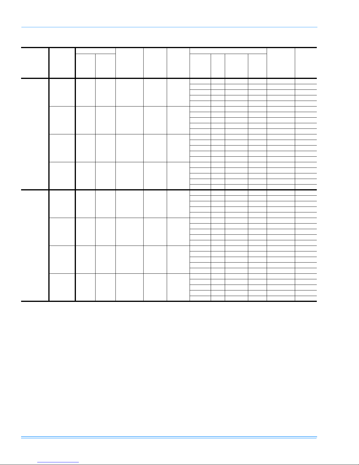
TABLE 9: DM 180, 240 ELECTRICAL DATA WITHOUT POWERED CONVENIENCE OUTLET
HEATER OPTION
MODEL KW STAGES AMPS
None 0.0 - - 85.4 100
E18 13.5 1 37.5 85.4 100
E36 27.0 2 75.1 111.2 125
E54 40.6 2 112.6 158.4 175
E72 54.1 2 150.1 167.7 200
None 0.0 - - 85.0 100
E18 18.0 1 43.3 85.0 100
E36 36.0 2 86.6 125.8 150
E54 54.0 2 129.9 147.4 175
E72 72.0 2 173.2 190.7 225
None 0.0 - - 42.6 50
E18 18.0 1 21.7 42.6 50
E36 36.0 2 43.3 62.9 70
E54 54.0 2 65.0 73.7 90
E72 72.0 2 86.6 95.4 110
None 0.0 - - 33.7 40
E18 18.0 1 17.3 33.7 40
E36 36.0 2 34.6 49.9 50
E54 54.0 2 52.0 58.6 70
E72 72.0 2 69.3 75.9 90
None 0.0 - - 110.3 125
E18 13.5 1 37.5 110.3 125
E36 27.0 2 75.1 118.2 125
E54 40.6 2 112.6 165.4 175
E72 54.1 2 150.1 174.7 200
None 0.0 - - 109.9 125
E18 18.0 1 43.3 109.9 125
E36 36.0 2 86.6 132.8 150
E54 54.0 2 129.9 154.4 175
E72 72.0 2 173.2 197.7 225
None 0.0 - - 55.1 60
E18 18.0 1 21.7 55.1 60
E36 36.0 2 43.3 66.4 70
E54 54.0 2 65.0 77.2 90
E72 72.0 2 86.6 98.6 110
None 0.0 - - 44.5 50
E18 18.0 1 17.3 44.5 50
E36 36.0 2 34.6 53.6 60
E54 54.0 2 52.0 62.2 70
E72 72.0 2 69.3 79.5 90
MODEL
(TON-
NAGE)
180
(15)
240
(20)
COMPRESSORS
OD FAN
VOLTAGE
208 19.2 124 4.5 14.0 0.0
230 19.2 124 4.3 14.0 0.0
460 9.6 62 2.2 7.0 0.0
575 7.7 50 1.7 5.3 0.0
208 19.2 124 4.5 19.6 0.0
230 19.2 124 4.3 19.6 0.0
460 9.6 62 2.2 9.8 0.0
575 7.7 50 1.7 8.2 0.0
RLA
EACH
LRA
EACH
MOTORS
FLA EACH
ID
BLOWER
MOTOR
FLA
CONV
OUTLET
AMPS
NOTE 1: HACR Type per NEC.
284806-YIM-A-0107
MIN.
CIRCUIT
AMPACITY
(AMPS)
MAX.
FUSE/
BRKR
SIZE
(AMPS)
1
24 Unitary Products Group
Page 25
284806-YIM-A-0107
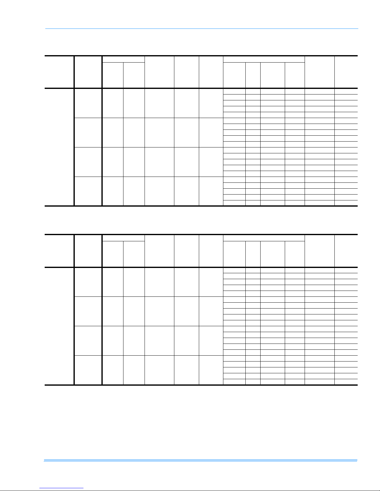
TABLE 10: DM 300 ELECTRICAL DATA STANDARD MOTOR WITHOUT POWERED CONVENIENCE OUTLET
COMPRESSORS
MODEL
(TON-
NAGE)
300
(25)
VOLTAGE
208 41.0 255 4.5 28.0 0.0
230 41.0 255 4.3 26.0 0.0
460 20.5 145 2.2 13.0 0.0
575 17.3 102 1.7 10.0 0.0
RLA
EACH
NOTE 1: HACR Type per NEC.
LRA
EACH
OD FAN
MOTORS
FLA EACH
ID
BLOWER
MOTOR
FLA
CONV
OUTLET
AMPS
HEATER OPTION
MIN.
CIRCUIT
MODEL KW STAGES AMPS
AMPACITY
(AMPS)
None - - - 129.3 150
E18 13.5 1 37.5 129.3 150
E36 27.0 2 74.9 129.3 150
E54 40.6 2 112.7 175.9 200
E72 54.1 2 150.2 185.2 200
None - - - 126.9 150
E18 18.0 1 43.3 126.9 150
E36 36.0 2 86.6 140.8 150
E54 54.0 2 129.9 162.4 175
E72 72.0 2 173.2 205.7 225
None - - - 63.5 80
E18 18.0 1 21.7 63.5 80
E36 36.0 2 43.3 70.4 80
E54 54.0 2 65.0 81.2 90
E72 72.0 2 86.6 102.9 110
None - - - 52.3 60
E18 18.0 1 17.3 52.3 60
E36 36.0 2 34.6 55.8 60
E54 54.0 2 52.0 64.5 70
E72 72.0 2 69.3 81.8 90
MAX.
FUSE/
BRKR
SIZE
(AMPS)
1
TABLE 11: DM 30 0 E LECTRICA L DATA HIGH STATIC MOTOR WITHOUT POWERED CONVENIENCE OUTLE T
MAX.
FUSE/
BRKR
SIZE
(AMPS)
MODEL
(TON-
NAGE)
300
(25)
COMPRESSORS
OD FAN
VOLTAGE
208 41.0 255 4.5 38.6 0.0
230 41.0 255 4.3 38.6 0.0
460 20.5 145 2.2 19.3 0.0
575 17.3 102 1.7 15.4 0.0
RLA
EACH
LRA
EACH
MOTORS
FLA EACH
ID
BLOWER
MOTOR
FLA
CONV
OUTLET
AMPS
HEATER OPTION
MIN.
CIRCUIT
MODEL KW STAGES AMPS
AMPACITY
(AMPS)
None - - - 139.9 175
E18 13.5 1 37.5 139.9 175
E36 27.0 2 74.9 141.9 175
E54 40.6 2 112.7 189.1 200
E72 54.1 2 150.2 198.4 225
None - - - 139.5 175
E18 18.0 1 43.3 139.5 175
E36 36.0 2 86.6 156.5 175
E54 54.0 2 129.9 178.2 200
E72 72.0 2 173.2 221.5 250
None - - - 69.8 90
E18 18.0 1 21.7 69.8 90
E36 36.0 2 43.3 78.3 90
E54 54.0 2 65.0 89.1 100
E72 72.0 2 86.6 110.7 125
None - - - 57.7 70
E18 18.0 1 17.3 57.7 70
E36 36.0 2 34.6 62.6 70
E54 54.0 2 52.0 71.2 80
E72 72.0 2 69.3 88.5 100
NOTE 1: HACR Type per NEC.
1
Unitary Products Group 25
Page 26
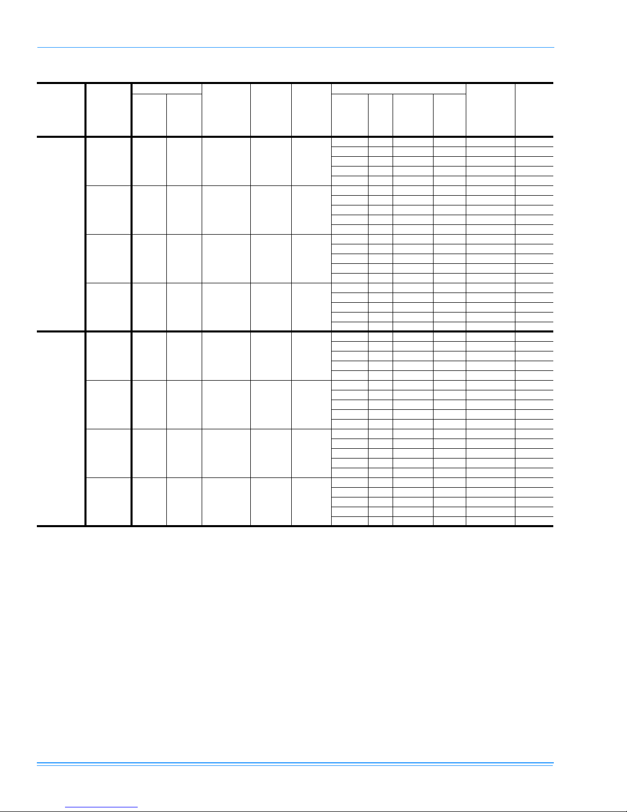
TABLE 12: DM 180, 240 ELECTRICAL DATA WITH POWERED CONVENIENCE OUTLET
HEATER OPTION
MODEL KW STAGES AMPS
None 0.0 - - 95.4 110
E18 13.5 1 37.5 95.4 110
E36 27.0 2 75.1 123.7 125
E54 40.6 2 112.6 170.9 175
E72 54.1 2 150.1 180.2 200
None 0.0 - - 95.0 110
E18 18.0 1 43.3 95.0 110
E36 36.0 2 86.6 138.3 150
E54 54.0 2 129.9 159.9 175
E72 72.0 2 173.2 203.2 225
None 0.0 - - 47.6 50
E18 18.0 1 21.7 47.6 50
E36 36.0 2 43.3 69.1 70
E54 54.0 2 65.0 80.0 90
E72 72.0 2 86.6 101.6 110
None 0.0 - - 37.7 45
E18 18.0 1 17.3 37.7 45
E36 36.0 2 34.6 54.9 60
E54 54.0 2 52.0 63.6 70
E72 72.0 2 69.3 80.9 90
None 0.0 - - 120.3 125
E18 13.5 1 37.5 120.3 125
E36 27.0 2 75.1 130.7 150
E54 40.6 2 112.6 177.9 200
E72 54.1 2 150.1 187.2 200
None 0.0 - - 119.9 125
E18 18.0 1 43.3 119.9 125
E36 36.0 2 86.6 145.3 150
E54 54.0 2 129.9 166.9 175
E72 72.0 2 173.2 210.2 225
None 0.0 - - 60.1 70
E18 18.0 1 21.7 60.1 70
E36 36.0 2 43.3 72.6 80
E54 54.0 2 65.0 83.5 90
E72 72.0 2 86.6 105.1 110
None 0.0 - - 48.5 50
E18 18.0 1 17.3 48.5 50
E36 36.0 2 34.6 58.6 60
E54 54.0 2 52.0 67.2 70
E72 72.0 2 69.3 84.5 90
MODEL
(TON-
NAGE)
180
(15)
240
(20)
COMPRESSORS
OD FAN
VOLTAGE
208 19.2 124 4.5 14.0 10.0
230 19.2 124 4.3 14.0 10.0
460 9.6 62 2.2 7.0 5.0
575 7.7 50 1.7 5.3 4.0
208 19.2 124 4.5 19.6 10.0
230 19.2 124 4.3 19.6 10.0
460 9.6 62 2.2 9.8 5.0
575 7.7 50 1.7 8.2 4.0
RLA
EACH
LRA
EACH
MOTORS
FLA EACH
ID
BLOWER
MOTOR
FLA
CONV
OUTLET
AMPS
NOTE 1: HACR Type per NEC.
284806-YIM-A-0107
MIN.
CIRCUIT
AMPACITY
(AMPS)
MAX.
FUSE/
BRKR
SIZE
(AMPS)
1
26 Unitary Products Group
Page 27
284806-YIM-A-0107
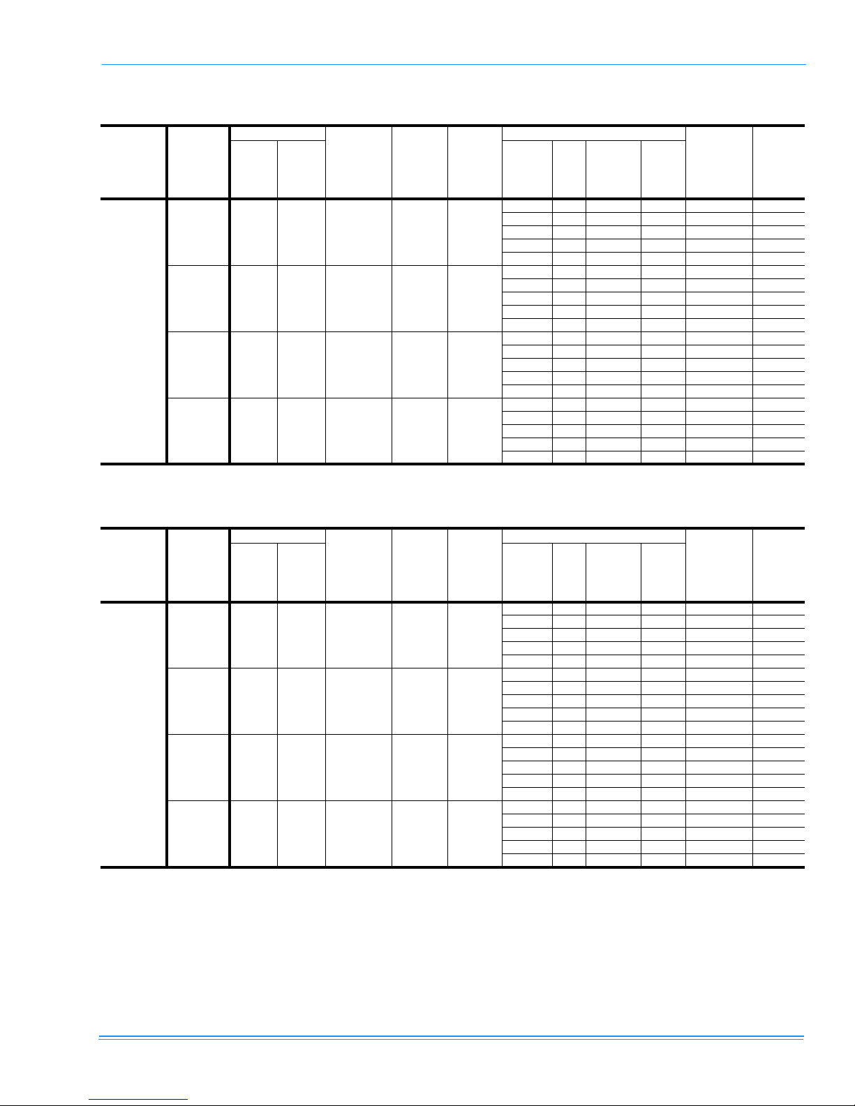
TABLE 13: DM 300 ELECTRICAL DATA STANDARD MOTOR WITH POWERED CONVENIENCE OUTLET
COMPRESSORS
MODEL
(TON-
NAGE)
300
(25)
VOLTAGE
208 41.0 255 4.5 28.0 10.0
230 41.0 255 4.3 26.0 10.0
460 20.5 145 2.2 13.0 5.0
575 17.3 102 1.7 10.0 4.0
RLA
EACH
NOTE 1: HACR Type per NEC.
LRA
EACH
OD FAN
MOTORS
FLA EACH
ID
BLOWER
MOTOR
FLA
CONV
OUTLET
AMPS
HEATER OPTION
MIN.
CIRCUIT
MODEL KW STAGES AMPS
AMPACITY
(AMPS)
None - - - 139.3 175
E18 13.5 1 37.5 139.3 175
E36 27.0 2 74.9 141.2 175
E54 40.6 2 112.7 188.4 200
E72 54.1 2 150.2 197.7 200
None - - - 136.9 175
E18 18.0 1 43.3 136.9 175
E36 36.0 2 86.6 153.3 175
E54 54.0 2 129.9 174.9 175
E72 72.0 2 173.2 218.2 225
None - - - 68.5 80
E18 18.0 1 21.7 68.5 80
E36 36.0 2 43.3 76.6 80
E54 54.0 2 65.0 87.5 90
E72 72.0 2 86.6 109.1 110
None - - - 56.3 70
E18 18.0 1 17.3 56.3 70
E36 36.0 2 34.6 60.8 70
E54 54.0 2 52.0 69.5 70
E72 72.0 2 69.3 86.8 90
FUSE/
BRKR
(AMPS)
MAX.
1
SIZE
TABLE 14: DM 300 ELECTRICAL DATA HIGH STATIC MOTOR WITH POWERED CONVENIENCE OUTLET
MAX.
FUSE/
BRKR
SIZE
(AMPS)
MODEL
(TON-
NAGE)
300
(25)
COMPRESSORS
OD FAN
VOLTAGE
208 41.0 255 4.5 38.6 10.0
230 41.0 255 4.3 38.6 10.0
460 20.5 145 2.2 19.3 5.0
575 17.3 102 1.7 15.4 4.0
RLA
EACH
LRA
EACH
MOTORS
FLA EACH
ID
BLOWER
MOTOR
FLA
CONV
OUTLET
AMPS
HEATER OPTION
MIN.
CIRCUIT
MODEL KW STAGES AMPS
AMPACITY
(AMPS)
None - - - 149.9 175
E18 13.5 1 37.5 149.9 175
E36 27.0 2 74.9 154.4 175
E54 40.6 2 112.7 201.6 225
E72 54.1 2 150.2 210.9 225
None - - - 149.5 175
E18 18.0 1 43.3 149.5 175
E36 36.0 2 86.6 169.0 175
E54 54.0 2 129.9 190.7 225
E72 72.0 2 173.2 234.0 250
None - - - 74.8 90
E18 18.0 1 21.7 74.8 90
E36 36.0 2 43.3 84.5 90
E54 54.0 2 65.0 95.3 110
E72 72.0 2 86.6 117.0 125
None - - - 61.7 70
E18 18.0 1 17.3 61.7 70
E36 36.0 2 34.6 67.6 70
E54 54.0 2 52.0 76.2 90
E72 72.0 2 69.3 93.5 100
NOTE 1: HACR Type per NEC.
1
Unitary Products Group 27
Page 28
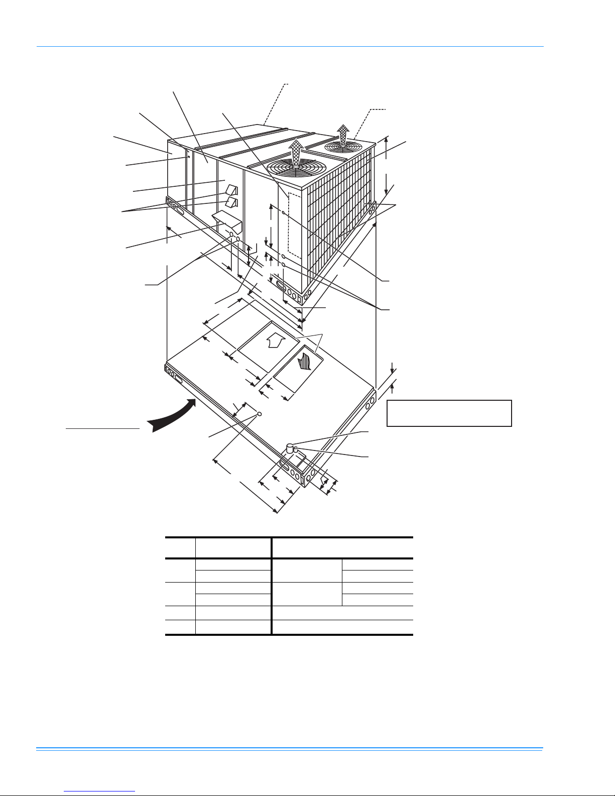
BLOWER ACCESS
(Location Of
Optional VFD)
BLOWER MOTOR ACCESS
(Location Of Optional
VFD Bypass)
BLOWER
COMPARTMENT
ACCESS
(Auxiliary)
DOT PLUG
(For pressure
Drop Reading)
ELECTRIC/
GAS HEAT
ACCESS
VENT AIR
OUTLET
HOODS
COMBUSTION
AIR INLET
HOOD
(C)
GAS SUPPLY
ENTRY
125-1/4"(15 TON)
136-1/4” (20, 25 TON)
FIELD-SUPPLIED
DISCONNECT SWITCH
LOCATION
CONTROL BOX
ACCESS
FRONT
VIEW
12-1/4"(15 TON)
35-1/4” (20, 25 TON)
UNIT BASE WITH RAILS
Shown separately to illustrate
Bottom Duct openings, Power
and Gas Piping Connection
locations
NOTE:
For curb mounted units, refer to the curb hanger
dimensions of the curb for the proper size of the
supply and return air duct connections.
(D)
GAS SUPPLY
ENTRY
6-3/8"
35"
11-1/8"
7-1/8"
)
33"
2-3/4" 21-1/2"
46-5/8"
21"
5"
9-3/4"
5-7/8"
46-5/8"
RETURN
AIR
12-1/2"
ECONOMIZER / MOTORIZED DAMPER,
FIXED OUTDOOR INTAKE AIR AND
POWER EXHAUST RAIN HOODS
(See detail "Y")
92"
11-1/2"
BOTTOM SUPPLY
AND RETURN
AIR OPENINGS
(See Note)
SUPPLY
AIR
(B)
POWER WIRING
ENTRY
(A)
8-1/8"
9-1/4"
9-3/4"
CONTROL WIRING
ENTRY
284806-YIM-A-0107
COMPRESSOR
ACCESS
COIL
GUARD
48-5/8"(15 TON)
52-5/8" (20, 25 TON)
CONDENSER
COILS
(A)
CONTROL WIRING
ENTRY
(B)
POWER WIRING
ENTRY
3-3/4"
All dimensions are in inches. They are
subject to change without notice. Certified
dimensions will be provided upon request.
HOLE
OPENING SIZE
A
3/4” NPS (Fem.) Bottom
B
C
D
1.
One-inch gas piping NPT required.
2.
Opening in the bottom of the unit can be located by the slice in
the insulation.
NOTE: All entry holes should be field sealed to prevent rain
FIGURE 13 - FRONT VIEW DIMENSIONS (15, 20 & 25 TON)
28 Unitary Products Group
UTILITIES ENTRY DATA
(DIA.)
1-1/8” KO
3-5/8” KO
3” NPS (Fem.) Bottom
Control Wiring
Power Wiring
2-3/8” KO
1-11/16” Hole
water entry into the building.
USED FOR
Gas Piping (Front)
Gas Piping (Bottom)
Side
Side
1
1, 2
Page 29
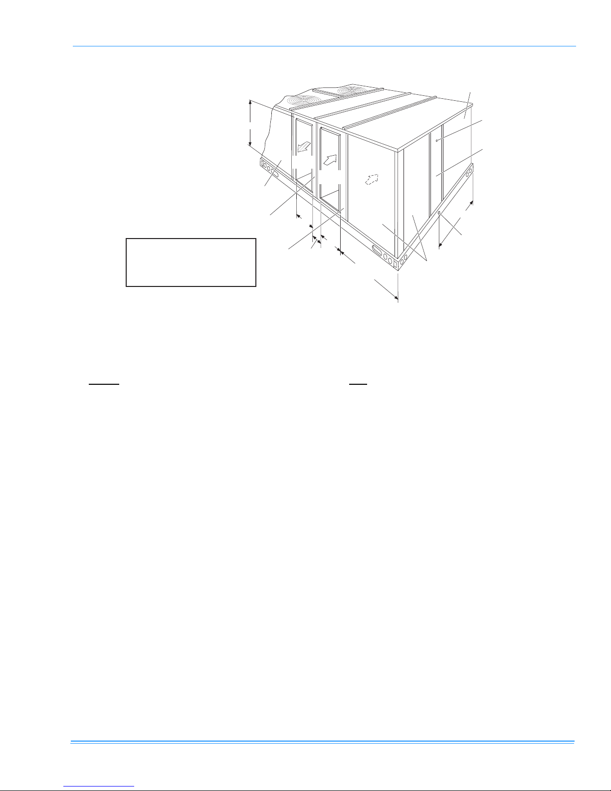
284806-YIM-A-0107
40-3/8"
COMPRESSOR
ACCESS
SUPPLY AIR
ACCESS
Dimensions listed are for side
duct flange openings; see
Field Accessories for Side
Duct Flange Kit.
FIGURE 14 - REAR VIEW DIMENSIONS
RETURN AIR
ACCESS
REAR
VIEW
SUPPLY
AIR
18-5/8"
5-1/8"
RETURN
AIR
27-3/4"
28-5/8” (15 TON)
39-5/8" (20, 25 TON)
OUTDOOR
AIR
40-1/2"
OUTDOOR AIR
COMPARTMENT
ACCESS
EVAPORATOR
SECTION
DOT PLUG
(For pressure
drop reading)
FILTER
ACCESS
1" NPT FEMALE
COND. DRAIN
CONNECTION
NOTE: Units are shipped with the bottom duct open-
ings covered. An accessory flange kit is available for connecting side ducts.
For bottom duct applications:
1. Remove the side panels from the supply and return air
compartments to gain access to the bottom supply and
return air duct covers.
2. Remove and discard the bottom duct covers. Duct
openings are closed with sheet metal covers except
when the unit includes a power exhaust option. The
covering consists of a heavy black paper composition.
3. Replace the side supply and return air compartment
panels.
For side duct applications:
1. Replace the side panels on the supply and return air
compartments with the side duct flange accessory kit
panels.
2. Connect ductwork to the flanges on those panels.
Unitary Products Group 29
Page 30
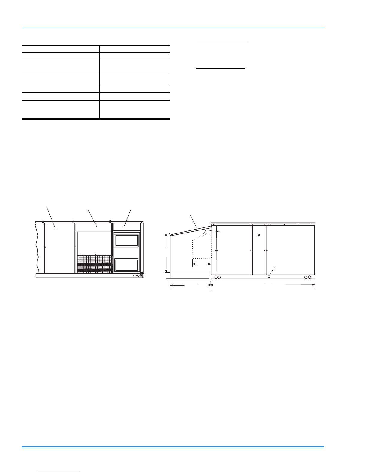
284806-YIM-A-0107
CLEARANCE
LOCATION
CLEARANCE
Front
Rear
Left Side (Filter Access)
24” (Less Economizer)
49” (With Economizer)
24” (Less Economizer)
36” (With Economizer)
Right Side (Cond. Coil)
Below Unit
Above Unit
1
2
72” With 36” Maximum
Horizontal Overhang (For
Condenser Air Discharge)
1.
Units may be installed on combustible floors made from wood or
class A, B, or C roof covering material.
2.
Units must be installed outdoors. Overhanging structures or
shrubs should not obstruct condenser air discharge outlet.
3. If economizer is factory installed, the unassembled rain hood
must be removed from its ride along position in front of evaporator coil, or in the outdoor air compartment, prior to final installation.
ECONOMIZER
MOTORIZED
SUPPLY AIR
COMPARTMENT
POWER EXHAUST
RAIN HOOD
(on Return Air Compartment)
DAMPER
RAIN HOOD
(on Outdoor Air Compartment)
36”
36”
0”
NOTE: ELEC / ELEC Models: Units and ductwork are
approved for zero clearance to combustible material
when equipped with electric heaters.
GAS / ELEC Models
: A 1” clearance must be
provided between any combustible material and the
3
supply air ductwork for a distance of 3 feet from the
unit.
The products of combustion must not be allowed to
accumulate within a confined space and recirculate.
Locate unit so that the vent air outlet hood is at least:
• Three (3) feet above any force air inlet located
within 10 horizontal feet (excluding those integral to
the unit).
• Four (4) feet below, four horizontal feet from, or one
foot above any door or gravity air inlet into the
building.
• Four (4) feet from electric and gas meters,
regulators and relief equipment.
ECONOMIZER / MOTORIZED DAMPER
AND POWER EXHAUST RAIN HOODS
FIXED
OUTDOOR AIR
INTAKE HOOD
(located on
Return Air
36-5/8”
16-1/8”
5”
28-3/16”
Compartment)
REAR VIEW
DETAIL “Y”
UNIT WITH RAIN HOODS
FIGURE 15 - UNIT CLEARANCE AND RAIN HOOD DIMENSIONS (15, 20 & 25 TON)
92”
LH VIEW
1“ CONDENSATE
DRAIN
(Must be trapped)
30 Unitary Products Group
Page 31
284806-YIM-A-0107
CFM, STATIC PRESSURE, AND POWER ALTITUDE AND TEMPERATURE CORRECTIONS
The information below should be used to assist in application
of product when being applied at altitudes at or exceeding
1000 feet above sea level.
order to use the indoor blower tables for high altitude applications, certain corrections are necessary.
A centrifugal fan is a "constant volume" device. This means
that, if the rpm remains constant, the CFM delivered is the
same regardless of the density of the air. However, since the
air at high altitude is less dense, less static pressure will be
The air flow rates listed in the standard blower performance
tables are based on standard air at sea level. As the altitude
or temperature increases, the density of air decreases. In
generated and less power will be required than a similar
application at sea level. Air density correction factors are
shown in Table 15 and Figure 16.
TABLE 15: ALTITUDE CORRECTION FACTORS
AIR TEMP
40 1.060 1.022 0.986 0.950 0.916 0.882 0.849 0.818 0.788 0.758 0.729
50 1.039 1.002 0.966 0.931 0.898 0.864 0.832 0.802 0.772 0.743 0.715
60 1.019 0.982 0.948 0.913 0.880 0.848 0.816 0.787 0.757 0.729 0.701
70 1.000 0.964 0.930 0.896 0.864 0.832 0.801 0.772 0.743 0.715 0.688
80 0.982 0.947 0.913 0.880 0.848 0.817 0.787 0.758 0.730 0.702 0.676
90 0.964 0.929 0.897 0.864 0.833 0.802 0.772 0.744 0.716 0.689 0.663
100 0.946 0.912 0.880 0.848 0.817 0.787 0.758 0.730 0.703 0.676 0.651
0 1000 2000 3000 4000 5000 6000 7000 8000 9000 10000
The examples below will assist in determining the airflow performance of the product at altitude.
Example 1: What are the corrected CFM, static pressure,
and BHP at an elevation of 5,000 ft. if the blower performance
data is 6,000 CFM, 1.5 IWC and 4.0 BHP?
Solution: At an elevation of 5,000 ft the indoor blower will still
deliver 6,000 CFM if the rpm is unchanged. However, Table
15 must be used to determine the static pressure and BHP.
Since no temperature data is given, we will assume an air
temperature of 70°F. Table 15 shows the correction factor to
be 0.832.
Corrected static pressure = 1.5 x 0.832 = 1.248 IWC
Corrected BHP = 4.0 x 0.832 = 3.328
ALTITUDE (FEET)
blower tables to select the blower speed and the BHP
requirement.
Solution: As in the example above, no temperature information is given so 70°F is assumed.
The 1.5" static pressure given is at an elevation of 5,000 ft.
The first step is to convert this static pressure to equivalent
sea level conditions.
Sea level static pressure = 1.5 / .832 = 1.80"
Enter the blower table at 6000 sCFM and static pressure of
1.8". The rpm listed will be the same rpm needed at 5,000 ft.
Suppose that the corresponding BHP listed in the table is 3.2.
This value must be corrected for elevation.
Example 2: A system, located at 5,000 feet of elevation, is to
deliver 6,000 CFM at a static pressure of 1.5". Use the unit
Unitary Products Group 31
BHP at 5,000 ft = 3.2 x .832 = 2.66
Page 32
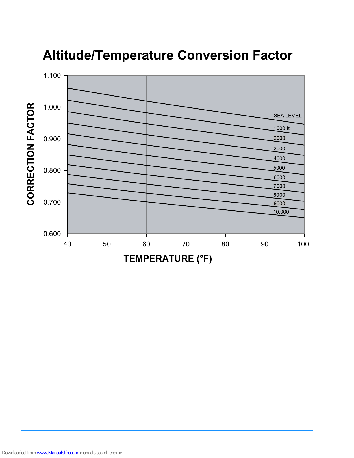
284806-YIM-A-0107
FIGURE 16 - ALTITUDE/TEMPERATURE CONVERSION FACTOR
32 Unitary Products Group
Page 33
284806-YIM-A-0107
TABLE 16: SUPPLY AIR BLOWER PERFORMANCE (15 TON) - COOLING ONLY
180 MBH - BOTTOM DUCT CONNECTIONS
BLOWER
SPEED,
(RPM)
208 VOLT AND STANDARD DRIVE
850 6.0** 0.9 2.4 2.2 0.7 3.0 2.7 0.5 3.2 2.9 - - - - - 870 5.5 1.0 2.5 2.3 0.8 3.1 2.8 0.6 3.5 3.1 0.2 4.1 3.7 - - 915 4.5 1.1 2.6 2.4 0.9 3.4 3.0 0.7 3.7 3.3 0.3 4.4 3.9 0.2 4.5 4.0
965 3.5 1.2 2.9 2.6 1.0 3.6 3.2 0.8 4.0 3.6 0.5 4.7 4.2 0.4 4.9 4.4
980 3.0 1.3 3.0 2.7 1.1 3.7 3.3 0.9 4.1 3.7 0.6 4.8. 4.3 0.5 5.1 4.6
1010 2.0 1.4 3.1 2.8 1.2 3.8 3.4 1.0 4.2 3.8 0.7 5.0 4.5 0.6 5.4 4.8
1040 1.0 1.5 3.2 2.9 1.3 3.9 3.5 1.1 4.5 4.0 0.9 5.2 4.7 0.7 5.7 5.1
208 VOLT AND HIGH SPEED DRIVE
965 6.0 1.2 2.9 2.6 1.0 3.6 3.2 0.8 4.0 3.6 0.5 4.7 4.2 0.4 5.0 4.4
980 5.5 1.3 3.0 2.7 1.1 3.7 3.3 0.9 4.1 3.7 0.6 4.8 4.3 0.5 5.1 4.6
1025 4.5 1.5 3.2 2.9 1.3 3.9 3.5 1.1 4.5 4.0 0.8 5.1 4.6 0.7 5.6 5.0
1065 3.5 1.6 3.4 3.0 1.4 4.0 3.6 1.2 4.7 4.2 1.0 5.5 4.9 - - 1095 3.0 1.7 3.5 3.1 1.5 4.2 3.8 1.3 4.9 4.4 1.2 5.7 5.1 - - -
1130 2.0 1.9 3.7 3.3 1.7 4.5 4.0 1.5 5.1 4.6 - - - - - 1170 1.0 2.1 3.9 3.5 2.0 4.7 4.2 1.8 5.5 4.9 - - - - - -
230/460/575 VOLT AND STANDARD DRIVE
870 6.0** 1.0 2.4 2.2 0.8 3.1 2.8 0.6 3.5 3.1 0.2 4.1 3.7 - - -
915 5.0 1.1 2.6 2.4 0.9 3.3 3.0 0.7 3.7 3.3 0.3 4.4 3.9 0.2 4.5 4.0
965 4.0 1.2 2.9 2.6 1.0 3.6 3.2 0.8 4.0 3.6 0.5 4.7 4.2 0.4 5.0 4.4
980 3.5 1.3 3.0 2.7 1.1 3.7 3.3 0.9 4.1 3.7 0.6 4.8 4.3 0.5 5.1 4.6
1040 2.0 1.5 3.2 2.9 1.3 3.9 3.5 1.1 4.5 4.0 0.9 5.3 4.7 0.7 5.7 5.1
1065 1.0 1.6 3.3 3.0 1.4 4.0 3.6 1.2 4.7 4.2 1.0 5.5 4.9 - - -
230/460/575 VOLT AND HIGH SPEED DRIVE
980 6.0 1.3 2.9 2.6 1.1 3.7 3.3 0.9 4.1 3.7 0.6 4.8 4.3 0.5 5.1 4.6
1040 4.5 1.5 3.2 2.9 1.3 3.9 3.5 1.1 4.5 4.0 0.9 5.3 4.7 0.7 5.7 5.1
1065 4.0 1.6 3.4 3.0 1.4 4.0 3.6 1.2 4.7 4.2 1.0 5.5 4.9 - - 1095 3.5 1.7 3.5 3.1 1.5 4.2 3.8 1.3 4.9 4.4 1.2 5.7 5.1 - - -
1130 2.5 1.9 3.7 3.3 1.7 4.5 4.0 1.5 5.1 4.6 - - - - - 1170 1.5 2.1 3.9 3.5 2.0 4.7 4.2 1.8 5.5 4.9 - - - - - 1190 1.0 2.2 4.0 3.6 2.1 4.8 4.3 2.0 5.7 5.1 - - - - - -
NOTES: 1. Blower performance includes fixed outdoor air, 2” T/A filters, a dry evaporator coil and no electric heat.
MOTOR
PULLEY
(TURNS
OPEN)*
2. Refer to Table 21 for additional static resistances.
ESP = External Static Pressure available for the supply and return air duct system. All internal unit resistances have been deducted from the
total static pressure of the blower.
close the pulley below 1 turn open.
* Do NOT
** Factory setting.
4500 5250 6000 6750 7200
ESP BHP KW ESP BHP KW ESP BHP KW ESP BHP KW ESP BHP KW
CFM
Unitary Products Group 33
Page 34
284806-YIM-A-0107
TABLE 17: SUPPLY AIR BLOWER PERFORMANCE (20 TON) - COOLING ONLY
240 MBH - BOTTOM DUCT CONNECTIONS
BLOWER
SPEED,
(RPM)
208 VOLT AND STANDARD DRIVE
8706.0**0.42.11.80.12.32.0--------900 5.0 0.8 3.2 2.7 0.5 3.5 2.9 0.2 3.8 3.2 - - - - - 930 4.0 1.1 4.1 3.4 0.9 4.5 3.8 0.6 4.9 4.1 0.1 5.1 4.3 - - 950 3.0 1.3 4.6 3.9 1.1 5.1 4.3 0.8 5.5 4.6 0.4 5.9 5.0 - - 980 2.0 1.6 5.3 4.5 1.4 5.8 4.9 1.2 6.3 5.3 0.7 6.9 5.8 0.2 7.3 6.1
1015 1.0 1.9 5.9 5.0 1.7 6.5 5.5 1.5 7.0 5.9 1.0 7.7 6.5 0.6 8.2 6.9
208 VOLT AND HIGH SPEED DRIVE
950 6.0 1.3 4.6 3.9 1.1 5.1 4.3 0.8 5.5 4.6 0.4 5.9 5.0 - - -
980 5.0 1.6 5.3 4.5 1.4 5.8 4.9 1.2 6.3 5.3 0.7 6.9 5.8 0.2 7.3 6.1
1010 4.0 1.8 5.8 4.9 1.7 6.3 5.3 1.5 6.9 5.8 1.0 7.5 6.3 0.5 7.9 6.7
1020 3.5 1.9 6.1 5.1 1.8 6.5 5.5 1.6 7.1 6.0 1.1 7.8 6.6 0.6 8.3 7.0
1035 3.0 2.0 6.2 5.2 1.9 6.8 5.7 1.7 7.4 6.2 1.2 8.1 6.8 0.7 8.6 7.3
1050 2.5 2.1 6.4 5.4 2.0 7.0 5.9 1.8 7.6 6.4 1.3 8.3 7.0 - - 1075 2.0 2.3 6.6 5.5 2.1 7.2 6.0 1.9 7.8 6.6 1.5 8.6 7.2 - - 1100 1.0 2.4 6.7 5.6 2.2 7.3 6.1 2.1 7.9 6.7 - - - - - -
230/460/575 VOLT AND STANDARD DRIVE
8706.0**0.42.11.80.12.32.0---------
900 5.0 0.8 3.2 2.7 0.5 3.5 2.9 0.2 3.8 3.2 - - - - - -
930 4.0 1.1 4.1 3.4 0.9 4.5 3.8 0.6 4.9 4.1 0.1 5.1 4.3 - - -
950 3.5 1.3 4.6 3.9 1.1 5.1 4.3 0.8 5.5 4.6 0.4 5.9 5.0 - - -
980 2.5 1.6 5.3 4.5 1.4 5.8 4.9 1.2 6.3 5.3 0.7 6.9 5.8 0.2 7.3 6.1
1015 1.5 1.9 5.9 5.0 1.7 6.5 5.5 1.5 7.0 5.9 1.0 7.7 6.5 0.6 8.2 6.9
1025 1.0 2.0 6.1 5.1 1.8 6.6 5.6 1.6 7.3 6.1 1.1 7.9 6.7 0.7 8.6 7.3
230/460/575 VOLT AND HIGH SPEED DRIVE
950 6.0 1.3 4.6 3.9 1.1 5.1 4.3 0.8 5.5 4.6 0.4 5.9 5.0 - - -
980 5.0 1.6 5.3 4.5 1.4 5.8 4.9 1.2 6.3 5.3 0.7 6.9 5.8 0.2 7.3 6.1
1015 4.0 1.9 5.9 5.0 1.7 6.5 5.5 1.5 7.0 5.9 1.0 7.7 6.5 0.6 8.2 6.9
1035 3.5 2.0 6.2 5.2 1.9 6.8 5.7 1.7 7.4 6.2 1.2 8.1 6.8 0.7 8.6 7.3
1050 3.0 2.1 6.4 5.4 2.0 7.0 5.9 1.8 7.6 6.4 1.3 8.3 7.0 - - 1080 2.0 2.3 6.6 5.5 2.1 7.2 6.0 1.9 7.8 6.6 1.5 8.6 7.2 - - 1100 1.5 2.4 6.7 5.6 2.2 7.3 6.1 2.1 7.9 6.7 - - - - - 1120 1.0 2.5 6.8 5.7 2.3 7.4 6.2 2.2 8.1 6.8 - - - - - -
NOTES: 1. Blower performance includes fixed outdoor air, 2” T/A filter s, a dry evaporator coil and no electric heat.
MOTOR
PULLEY
(TURNS
OPEN)*
2. Refer to Table 21 for additional static resistances.
ESP = External Static Pressure availa ble for the supply and return air duct system. All internal unit resistances have been deducted from the
total static pressure of the blower.
* Do NOT
** Factory setting.
close the pulley below 1 turn open.
6000 7000 8000 9000 9400
ESP BHP KW ESP BHP KW ESP BHP KW ESP BHP KW ESP BHP KW
CFM
34 Unitary Products Group
Page 35
284806-YIM-A-0107
TABLE 18: SUPPLY AIR BLOWER PERFORMANCE (15 TON) - GAS HEAT
180 MBH - BOTTOM DUCT CONNECTIONS
BLOWER
SPEED,
(RPM)
208 VOLT AND STANDARD DRIVE
850 6.0** 0.9 2.4 2.1 0.6 2.9 2.6 0.3 3.4 3.0 - - - - - 870 5.5 1.0 2.5 2.2 0.7 3.0 2.7 0.4 3.5 3.1 - - - - - 915 4.5 1.1 2.6 2.4 0.8 3.1 2.8 0.5 3.6 3.2 0.2 4.1 3.7 - - 965 3.5 1.2 2.7 2.5 0.9 3.2 2.9 0.6 3.7 3.3 0.4 4.4 3.0 0.2 5.0 4.5
980 3.0 1.3 2.9 2.6 1.0 3.4 3.0 0.7 3.8 3.4 0.5 4.5 4.0 0.3 5.1 4.6
1010 2.0 1.4 3.0 2.7 1.1 3.6 3.2 0.8 4.0 3.6 0.6 4.7 4.2 0.4 5.4 4.8
1040 1.0 1.6 3.2 2.9 1.3 3.8 3.4 1.0 4.4 3.9 0.8 5.0 4.5 0.6 5.6 5.0
208 VOLT AND HIGH SPEED DRIVE
965 6.0 1.2 2.7 2.5 0.9 3.2 2.9 0.6 3.7 3.3 0.4 4.4 3.9 0.2 5.0 4.5
980 5.5 1.3 2.9 2.6 1.0 3.4 3.0 0.7 3.8 3.4 0.5 4.5 4.0 0.3 5.1 4.6
1025 4.5 1.4 3.1 2.8 1.2 3.6 3.2 0.9 4.1 3.7 0.7 4.8 4.3 0.4 5.5 4.9
1065 3.5 1.6 3.4 3.0 1.4 3.9 3.5 1.1 4.5 4.0 0.9 5.1 4.6 - - -
1125 2.0 1.9 3.6 3.2 1.7 4.4 3.9 1.4 5.0 4.5 1.2 5.8 5.2 - - 1170 1.0 2.1 3.9 3.5 1.9 4.7 4.2 1.6 5.5 4.9 - - - - - -
230/460/575 VOLT AND STANDARD DRIVE
870 6.0** 1.0 2.5 2.2 0.7 3.0 2.7 0.4 3.5 3.1 - - - - - -
915 5.0 1.1 2.6 2.4 0.8 3.1 2.8 0.5 3.6 3.2 0.2 4.1 3.7 - - -
965 4.0 1.2 2.7 2.5 0.9 3.2 2.9 0.6 3.7 3.3 0.4 4.4 3.9 0.2 5.0 4.5
980 3.5 1.3 2.9 2.6 1.0 3.4 3.0 0.7 3.8 3.4 0.5 4.5 4.0 0.3 5.1 4.6
1015 2.5 1.4 3.0 2.7 1.1 3.6 3.2 0.8 4.0 3.6 0.6 4.7 4.2 0.4 5.4 4.8
1050 1.5 1.5 3.1 2.8 1.2 3.7 3.3 0.9 4.2 3.8 0.7 4.9 4.4 0.5 5.7 5.1
1065 1.0 1.6 3.4 3.0 1.4 3.9 3.5 1.1 4.5 4.0 0.9 5.1 4.6 - - -
230/460/575 VOLT AND HIGH SPEED DRIVE
980 6.0 1.3 2.9 2.6 1.0 3.4 3.0 0.7 3.8 3.4 0.5 4.5 4.0 0.3 5.1 4.6
1045 4.5 1.6 3.2 2.9 1.3 3.8 3.4 1.0 4.4 3.9 0.8 5.0 4.5 0.6 5.6 5.0
1065 4.0 1.7 3.4 3.0 1.4 3.9 3.5 1.1 4.5 4.0 0.9 5.1 4.6 - - -
1125 2.5 1.9 3.6 3.2 1.7 4.4 3.9 1.4 5.0 4.5 1.2 5.8 5.2 - - 1170 1.5 2.1 3.9 3.5 1.8 4.7 4.2 1.6 5.5 4.9 - - - - - 1190 1.0 2.2 4.0 3.6 1.9 4.8 4.3 1.7 5.6 5.0 - - - - - -
MOTOR
PULLEY
(TURNS
OPEN)*
4500 5250 6000 6750 7200
ESP BHP KW ESP BHP KW ESP BHP KW ESP BHP KW ESP BHP KW
CFM
NOTES: 1. Blower performance includes a gas-fired heat exchanger, fixed outdoor air, two-inch T/A filters and a dry evaporator coil.
2. Refer to the additional Static Resistances table.
ESP = External Static Pressure available for the supply and return air duct system. All internal unit resistances have been deducted from the
total static pressure of the blower.
* Do NOT
close the pulley below 1 turn open.
** Factory setting.
Unitary Products Group 35
Page 36
284806-YIM-A-0107
TABLE 19: SUPPLY AIR BLOWER PERFORMANCE (20 TON) - GAS HEAT
240 MBH - BOTTOM DUCT CONNECTIONS
BLOWER
SPEED,
(RPM)
208 VOLT AND STANDARD DRIVE
870 6.0** 1.3 3.6 3.0 0.7 4.3 3.7 0.2 5.1 4.3 - - - - - 900 5.0 1.4 3.8 3.2 0.9 4.7 4.0 0.4 5.6 4.7 - - - - - 930 4.0 1.6 4.1 3.4 1.1 5.0 4.2 0.6 5.9 5.0 0.1 6.7 5.7 - - 950 3.0 1.7 4.2 3.6 1.3 5.1 4.3 0.8 6.0 5.1 0.2 6.9 5.8 - - 980 2.0 1.9 4.5 3.8 1.5 5.4 4.5 1.0 6.3 5.3 0.4 7.2 6.1 0.1 8.5 7.1
995 1.5 2.1 4.6 3.9 1.6 5.5 4.7 1.1 6.4 5.4 0.5 7.5 6.3 0.2 8.6 7.3
1015 1.0 2.2 4.8 4.0 1.7 4.7 4.8 1.2 6.6 5.6 0.7 7.8 6.6 - - -
208 VOLT AND HIGH SPEED DRIVE
950 6.0 1.7 4.2 3.6 1.3 5.1 4.3 0.8 6.0 5.1 0.2 6.9 5.8 - - 980 5.0 1.9 4.5 3.8 1.5 5.4 4.5 1.0 6.3 5.3 0.4 7.2 6.1 0.1 8.5 7.1
995 4.5 2.1 4.5 3.9 1.6 5.5 4.7 1.1 6.4 5.4 0.5 7.5 6.3 0.2 8.6 7.3
1025 3.5 2.3 4.9 4.1 1.8 5.8 4.9 1.3 6.7 5.7 0.7 8.0 6.7 - - 1050 2.5 2.5 5.1 4.3 2.0 6.1 5.1 1.4 7.1 6.0 0.9 8.4 7.0 - - 1065 2.0 2.6 5.3 4.4 2.1 6.3 5.3 1.5 7.3 6.2 1.0 8.6 7.2 - - 1100 1.0 2.9 5.6 4.7 2.3 6.8 5.7 1.8 7.9 6.6 - - - - - -
230/460/575 VOLT AND STANDARD DRIVE
870 6.0** 1.3 3.6 3.0 0.7 4.3 3.7 0.2 5.1 4.3 - - - - - -
900 5.0 1.4 3.8 3.2 0.9 4.7 4.0 0.4 5.6 4.7 - - - - - -
930 4.0 1.6 4.1 3.4 1.1 5.0 4.2 0.6 5.9 5.0 0.1 6.7 5.7 - - -
950 3.5 1.7 4.2 3.6 1.3 5.1 4.3 0.8 6.0 5.1 0.2 6.9 5.8 - - -
965 2.5 1.9 4.5 3.8 1.5 5.4 4.5 1.0 6.3 5.3 0.4 7.2 6.1 0.1 8.5 7.1
995 2.0 2.1 4.6 3.9 1.6 5.5 4.7 1.1 6.4 5.4 0.5 7.5 6.3 0.2 8.6 7.3
1015 1.5 2.2 4.8 4.0 1.7 5.7 4.8 1.2 6.6 5.6 0.6 7.8 6.6 - - 1025 1.0 2.3 4.9 4.1 1.8 5.8 4.9 1.3 6.7 5.7 0.7 8.0 6.7 - - -
230/460/575 VOLT AND HIGH SPEED DRIVE
950 6.0 1.7 4.2 3.6 1.3 5.1 4.3 0.8 6.0 5.1 0.2 6.9 5.8 - - -
980 5.0 1.9 4.5 3.8 1.5 5.4 4.5 1.0 6.3 5.3 0.4 7.2 6.1 0.1 8.5 7.1
995 4.5 2.1 4.6 3.9 1.6 5.5 4.7 1.1 6.4 5.4 0.5 7.5 6.3 0.2 8.6 7.3
1015 4.0 2.2 4.8 4.0 1.7 5.7 4.8 1.2 6.6 5.6 0.6 7.8 6.6 - - 1025 3.5 2.3 4.9 4.1 1.8 5.8 4.9 1.3 6.7 5.7 0.7 8.0 6.7 - - 1050 3.0 2.5 5.1 4.3 2.0 6.1 5.1 1.4 7.1 6.0 0.9 8.4 7.0 - - 1065 2.5 2.6 5.3 4.4 2.1 6.3 5.3 1.5 7.3 6.2 1.0 8.6 7.2 - - 1100 1.5 2.9 5.6 4.7 2.3 6.8 4.7 1.8 7.9 6.6 - - - - - 1120 1.0 3.1 5.8 4.9 2.5 7.0 5.9 1.9 8.3 6.9 - - - - -
MOTOR
PULLEY
(TURNS
OPEN)*
6000 7000 8000 9000 9400
ESP BHP KW ESP BHP KW ESP BHP KW ESP BHP KW ESP BHP KW
CFM
NOTES: 1. Blower performance includes a gas-fired heat exchanger, fixed outdoor air, two-inch T/A filters and a dry evaporator coil.
2. Refer to the additional Static Resistances table.
ESP = External Static Pressure availa ble for the supply and return air duct system. All internal unit resistances have been deducted from the
total static pressure of the blower.
* Do NOT
** Factory setting.
close the pulley below 1 turn open.
36 Unitary Products Group
Page 37
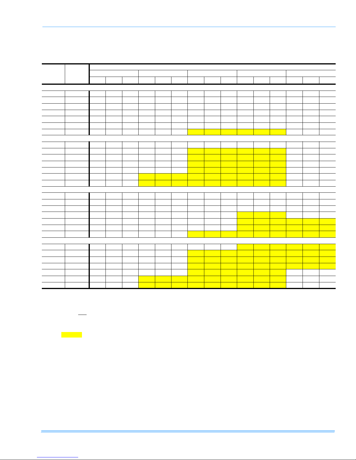
284806-YIM-A-0107
TABLE 20: SUPPLY AIR BLOWER PERFORMANCE (25 TON) - GAS HEAT
300 MBH - BOTTOM DUCT CONNECTIONS
BLOWER
SPEED,
(RPM)
208 VOLT AND STANDARD DRIVE
975 6.01.25.94.95.07.36.0--------1005 5.01.46.25.10.77.76.3--------1040 4.0 1.6 6.6 5.4 0.9 8.1 6.7 0.2 9.7 8.0 - - - - - 1070 3.0 1.8 6.9 5.7 1.1 8.5 7.0 0.4 10.2 8.3 - - - - - -
1100 2.0 2.0 7.3 6.0 1.3 8.9 7.3 0.6 10.6 8.7 - - - - - 1135 1.0 2.2 7.7 6.3 1.6 9.3 7.6 0.8 11.1 9.1 - - - - - 1165 0.0 2.4 8.0 6.6 1.8 9.7 8.0
208 VOLT AND HIGH SPEED DRIVE
1140 6.0 2.2 7.7 6.3 1.6 9.4 7.7 0.9 11.2 9.2 - - - - - -
1180 5.0 2.5 8.2 6.7 1.9 9.9 8.1
1215 4.0 2.7 8.6 7.0 2.1 10.4 8.5
1255 3.0 3.0 9.1 7.4 2.4 11.0 9.0
1290 2.0 3.2 9.5 7.8 2.7 11.5 9.4
1330 1.0 3.5 10.0 8.2
1365 0.0 3.7 10.5 8.6
230/460/575 VOLT AND STANDARD DRIVE
975 6.0* 1.4 5.9 4.9 1.0 7.3 6.0 0.5 8.8 7.2 - - - - - 1005 5.0 1.6 6.2 5.1 1.2 7.7 6.3 0.7 9.2 7.6 0.1 10.9 8.9 - - 1040 4.0 1.8 6.6 5.4 1.4 8.1 6.7 0.9 9.7 8.0 0.3 11.4 9.4 - - 1070 3.0 2.0 6.9 5.7 1.6 8.5 7.0 1.1 10.2 8.3
1100 2.0 2.1 7.3 6.0 1.8 8.9 7.3 1.3 10.6 8.7
1135 1.0 2.4 7.7 6.3 2.0 9.3 7.6 1.6 11.1 9.1
1165 0.0 2.6 8.0 6.6 2.2 9.7 8.0
230/460/575 VOLT AND HIGH SPEED DRIVE
1140 6.0 2.4 7.7 6.3 2.1 9.4 7.7 1.6 11.2 9.2
1180 5.0 2.7 8.2 6.7 2.3 9.9 8.1
1215 4.0 2.9 8.6 7.0 2.6 10.4 8.5
1255 3.0 3.2 9.1 7.4 2.9 11.0 9.0
1290 2.0 3.4 9.5 7.8 3.1 11.5 9.4
1330 1.0 3.7 10.0 8.2
1365 0.0 3.9 10.5 8.6
MOTOR
PULLEY
(TURNS
OPEN)*
7500 8750 10000 11250 12500
ESP BHP KW ESP BHP KW ESP BHP KW ESP BHP KW ESP BHP KW
3.0 12.0 9.9 2.3 14.1 11.6 1.5 16.4 13.4---
3.2 12.6 10.3 2.6 14.7 12.1 1.8 17.0 13.9---
3.4 12.0 9.9 3.0 14.1 11.6 2.6 16.4 13.4---
3.7 12.6 10.3 3.3 14.7 12.1 2.9 17.0 13.9---
CFM
1.0 11.6 9.5 0.2 13.5 11.0---
1.2 11.8 9.7 0.3 13.7 11.2---
1.4 12.3 10.1 0.6 14.3 11.7---
1.7 12.9 10.6 0.9 15.0 12.3---
2.0 13.5 11.1 1.2 15.6 12.8---
0.6 11.9 9.8---
0.8 12.4 10.2 0.2 14.3 11.7
1.0 13.0 10.6 0.4 14.9 12.2
1.8 11.6 9.5 1.3 13.5 11.0 0.7 15.5 12.7
1.1 13.1 10.7 0.5 15.0 12.3
1.9 11.8 9.7 1.4 13.7 11.2 0.8 15.8 12.9
2.2 12.3 10.1 1.7 14.3 11.7 1.1 16.4 13.5
2.5 12.9 10.6 2.0 15.0 12.3 1.4 17.2 14.1
2.7 13.5 11.1 2.2 15.6 12.8---
NOTES: 1. Blower performance includes a gas-fired heat exchanger, fixed outdoor air, two-inch T/A filters and a dry evaporator coil.
2. Refer to the additional Static Resistances table.
ESP = External Static Pressure available for the supply and return air duct system. All internal unit resistances have been deducted from the
total static pressure of the blower.
close the pulley below 1 turn open.
* Do NOT
** Factory setting.
15 HP Motor is required.
Unitary Products Group 37
Page 38
284806-YIM-A-0107
TABLE 21: STATIC RESISTANCES
1
RESISTANCE, IWG
DESCRIPTION
15 TON 20 TON 25 TON
CFM
4500 6000 7200 6000 8000 9400 7500 10000 12500
WET INDOOR COIL 0.1 0.1 0.1 0.1 0.1 0.1 0.1 0.1 0.1
18 KW 0.3 0.4 0.4 0.4 0.4 0.5 0.4 0.5 0.6
ELECTRIC HEAT OPTIONS
36 KW 0.3 0.4 0.5 0.4 0.5 0.5 0.5 0.5 0.6
54 KW 0.4 0.5 0.5 0.5 0.5 0.6 0.5 0.6 0.7
72 KW 0.4 0.5 0.5 0.5 0.5 0.6 0.5 0.6 0.7
ECONOMIZER OPTION 0.1 0.1 0.1 0.1 0.1 0.2 0.1 0.2 0.3
HORIZONTAL DUCT CONNECTIONS
1.
Deduct these resistance values from the available external static pressures shown in the respective Blower Performance T able (See Note 2 for
exception.)
2.
Since the resistance to air flow will be less for horizontal duct connections than for bottom duct connections, add these pressures to the ESP values
on the respective unit’s blower performance table.
2
0.1 0.2 0.3 0.2 0.3 0.5 0.3 0.5 0.6
TABLE 22: POWER EXHAUST PERFORMANCE
MOTOR
SPEED
0.2 0.3 0.4 0.5 0.6
CFM KW CFM KW CFM KW CFM KW CFM KW
HIGH* 5250 0.83 4500 0.85 4200 0.88 3750 0.93 3000 0.99
MEDIUM 4900 0.77 3900 0.79 3500 0.82 2900 0.85 - -
LOW 4400 0.72 3700 0.74 3000 0.78 - - - -
STATIC RESISTANCE OF RETURN DUCTWORK, IWG
* Factory Setting
Power Exhaust motor is a 3/4 HP, PSC type with sleeve bearings, a 48 frame and inherent protection.
TABLE 23: BLOWER MOTOR AND DRIVE DATA
1
MODEL
SIZE
Standard 850/1065
15 TON
Standard 870/1025
20 TON
Standard 950/1120 10 215 T 89.5 1VP68 6.75 5.5-6.5
25 TON
1.
All motors have a nominal speed of 1800 RPM, a 1.15 service factor and a solid base. They can operate to the limit of their service factor because
they are located in the moving air, upstream of any heat ing device.
2.
Do NOT close this pulley below 1 turn open.
BLOWER
DRIVE
Speed
Access
Speed
Access
Speed
Access
RANGE
(RPM)
High
965/1190 BK80 7.75 7.4 1 BX68 69.8 1
High
950/1120 BK110 10.75 10.4 1-3/16 BX81 82.8 1
High
1140/1365 15 254 T 91 1VP75X 7.5 6.2-7.4 1-5/8 1B5V94 9.7 9.5 1-7/16 5VX840 84.0 1
MOTOR
HP FRAME
5 184 T 83 1VP56 5.35
7.5 213 T 89 1VP68 6.75
EFF.
(%)
ADJUSTABLE MOTOR PULLEY FIXED BLOWER PULLEY
DESIG-
NATION
OUTSIDE
DIA.
(IN.)
PITCH
DIA.
(IN.)
4.3-5.3
5.5-6.5
BORE
(IN.)
NATION
2
1-1/8
2
1-3/8
2
1-3/8 1B5V110 11.3 11.1 1-7/16 BX81 82.8 1
OUTSIDE
DESIG-
BK90 8.75 8.4 1 BX70 82.8 1
BK120 11.75 11.4 1-3/16 BX83 84.8 1
DIA.
(IN.)
PITCH
DIA.
(IN.)
BORE
(IN.)
DESIG-
NATION
BELT
(NOTCHED)
PITCH
LENGTH
(IN.)
QTY.
38 Unitary Products Group
Page 39
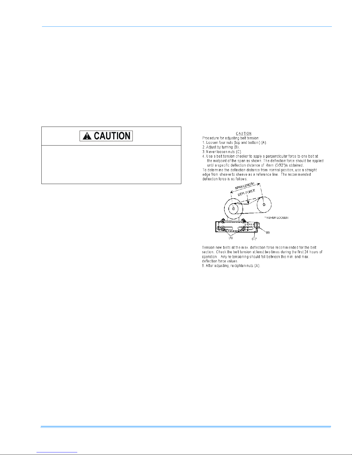
284806-YIM-A-0107
PHASING
®
YORK
MODEL DM, units are properly phased at the
factory. Check for proper compressor rotation. If the
blower or compressors rotate in the wrong direction at
start-up, the electrical connection to the unit is misphased. Change the incoming line connection phasing
to obtain proper rotation. (Scroll co mpressors operate
in only one direction. If the scroll is drawing low amperage, has similar suction and discharge pressures, or
producing a high noise level, the scroll is misphased).
Scroll compressors require proper rotation to
operate correctly. Units are properly phased at
the factory. Do not change the internal wiring to
make the blower, condenser fans, or compressor rotate correctly.
CHECKING SUPPLY AIR CFM
The RPM of the supply air blower will depend on the
required CFM, the unit accessories or options and the
static resistances of both the supply and the return air
duct systems. With this information, the RPM for the
supply air blower and the motor pulley adjustment
(turns open) can be determined from the Blower Performance Data Tables.
Note the following:
1. The supply air CFM must be within the limitations
shown in the Unit Application Data Table 1.
2. Pulleys can be adjusted in half turn increments.
3. The tension on the belt should be adjusted as
shown in the Belt Adjustment Figure 17.
High speed drive accessories (containing a smaller
blower pulley and a shorter belt) are available for applications requiring the supply air blower to produce
higher CFM's and/or higher static pressures. Use
Model 1LD0416 for 15 ton units, Model 1LD0 417 for 2 0
ton units, and Model 1LD0435 for 25 ton units. Refer to
the Blower Motor and Drive Data Table 23.
FIGURE 17 - BELT ADJUSTMENT
Unitary Products Group 39
Page 40
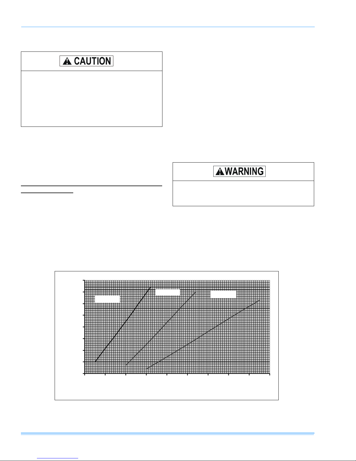
284806-YIM-A-0107
AIR BALANCE
On VAV units be certain that the VFD drive is
set to maximum output, exhaust dampers are
closed and individual space damper boxes are
full open.
VFD units with bypass must not be in bypass
mode (‘LINE’ position) unless all individual
space dampers are full open.
Start the supply air blower motor. Adjust the resistances in both the supply and the return air duct systems to balance the air distribution throughout the
conditioned space. The job specifications may require
that this balancing be done by someone other than the
equipment installer.
To check the supply air CFM after the initial balancing
has been completed:
1. Remove the two 5/16" dot plugs from the blower
motor and the filter access panels shown in the
Dimensions and Clearances Figure 13.
2. Insert at least 8" of 1/4 inch tubing into each of
these holes for sufficient penetration into the air
flow on both sides of the indoor coil.
NOTE: The tubes must be inserted and held in a posi-
tion perpendicular to the air flow so that velocity pressure will not affect the static pressure
readings.
3. Using an inclined manometer, determine the pressure drop across a dry evaporator coil. Since the
moisture on an evaporator coil may vary greatly,
measuring the pressure drop across a wet coil
under field conditions would be inaccurate. To
assure a dry coil, the compressors should be deactivated while the test is being run.
4. Knowing the pressure drop across a dry coil, the
actual CFM through the unit can be determined
from the curve in Pressure Drop vs. Supply Air
CFM Figure 18.
Failure to properly adjust the total system air
quantity can result in extensive blower damage.
After readings have been obtained, remove the tubes
and reinstall the two 5/16" dot plugs that were removed
in Step 1.
NOTE: DE-ENERGIZE THE COMPRESSORS
BEFORE TAKING ANY TEST MEASUREMENTS TO ASSURE A DRY INDOOR COIL.
0.65
PRESSURE DROP ( IWG )
0.6
0.55
0.5
0.45
0.4
0.35
0.3
0.25
180 MBH
45678910111213
NOM INA L CFM (THO USA NDS) SUPPLY AIR
240 MBH
300 MBH
FIGURE 18 - PRESSURE DROP ACROSS A DRY INDOOR COIL VS SUPPLY AIR CFM FOR ALL UNIT TONNAGES
40 Unitary Products Group
Page 41
284806-YIM-A-0107
OPERATION
SEQUENCE OF OPERATIONS OVERVIEW
For these units, the thermostat makes a circuit
between "R" and "Y1" for the first stage of cooling.
The call is passed to the unit control board (UCB),
which then determines whether the requested operation is available and, if so, which components to energize.
For gas heating, the UCB monitors the "W1" call but
does not handle the operation of the gas furnace. An
ignition control board controls the gas heater operation.
For electric heat units, the UCB passes the call to the
electric heater.
In both cases, when the "W1" call is sensed, the indoor
air blower is energized following a specified heating
delay.
If at any time a call for both heating and cooling are
present, the heating operation will be performed. If
operating, the cooling system is halted as with a completion of a call for cooling. Heating always takes priority.
COOLING SEQUENCE OF OPERATION
CONTINUOUS BLOWER
By setting the room thermostat fan switch to "ON," the
supply air blower will operate continuously.
INTERMITTENT BLOWER
With the room thermostat fan switch set to "AUTO" and
the system switch set to either the "AUTO" or "HEAT"
settings, the blower is energized whenever a cooling or
heating operation is requested. The blower is energized after any specified delay associated with the
operation.
When energized, the indoor blower has a minimum run
time of 30 seconds. Additionally, the indoor blower has
a delay of 10 seconds between operations.
If the unit is operated with the manual bypass
switch in the LINE (BYPASS) position and
there are VAV boxes present in the duct system, then boxes must be driven to the full-open
position using a customer-supplied power
source to prevent over-pressur izing and possible damage to the ductwork.
NO OUTDOOR AIR OPTIONS
When the thermostat calls for the first stage of cooling,
the low-voltage control circuit from "R" to "Y1" and "G"
is completed. For first stage cooling, compressor #1,
condenser fan motor #1, and condenser fan motor #2
for 15 and 20T only (if the ambient temperature is
above 60ºF), are energized. After completing the specified fan on delay for cooling, the UCB will energize the
blower motor.
When the thermostat calls for the second stage o f cooling, the low-voltage control circuit from "R" to "Y2" is
completed. Compressor #2, and condenser fan motor
#2, 25T only (if the ambient temperature is above
60ºF), is energized, provided it has not been lockedout.
If there is an initial call for both stages of cooling, the
UCB will delay energizing compressor #2 by 30 seconds in order to avoid a power in rush.
Once the thermostat has been satisfied, it will de-energize Y1 and Y2. If the compressors have satisfied their
minimum run times, the compressors and condenser
fans are de-energized. Otherwise, the unit operates
each cooling system until the minimum run times for
the compressors have been completed. Upon the final
compressor de-energizing, the blower is stopped following the elapse of the fan off delay for cooling.
To be available, a compressor must not be locked-out
due to a high or low-pressure swit ch or freezestat trip
and the anti-short cycle delay (ASCD) must have
elapsed.
VAV BLOWER OPERATION
For units with VFD, the speed of the indoor blower
motor is controlled by duct static pressure. The duct
static set point is the pressure that the drive will maintain when operating the unit in VAV mode. If the duct
static pressure reaches or exceeds the high-limit setpoint, then the supply fan motor will be shutdown.
Unitary Products Group 41
ECONOMIZER WITH SINGLE ENTHALPY SENSOR -
When the room thermostat calls for "first-stage" cooling, the low voltage control circuit from "R" to "G" and
"Y1" is completed. The UCB energizes the blower
motor (if the fan switch on the room thermostat is set in
the "AUTO" position) and drives the economizer dampers from fully closed to their minimum position. If the
Page 42

284806-YIM-A-0107
enthalpy of the outdoor air is below th e setpoint of the
enthalpy controller (previously determined), "Y1" energizes the economizer. The dampers will modulate to
maintain a constant supply air temperature as monitored by the discharge air sensor. If the outdoor air
enthalpy is above the setpoint, "Y1" energizes compressor #1, condenser fan motor #1, and condenser
fan motor #2, 15 and 20T only (if the ambient temperature is above 60°F).
When the thermostat calls for "second-stage" cooling,
the low voltage control circuit from "R" to "Y2" is
completed. The UCB energizes the first available
compressor If the enthalpy of the outdoor air is below
the setpoint of the enthalpy controller (i.e. first stage
has energized the economizer), "Y2" will energize
compressor #1. If the outdoor air is above the setpoint,
"Y2" will energize compressor #2.
Once the thermostat has been satisfied, it will de-energize Y1 and Y2. If the compressors have satisfied their
minimum run times, the compressors and condenser
fans are de-energized. Otherwise, the unit operates
each cooling system until the minimum run times for
the compressors have been completed. Upon the final
compressor de-energizing, the blower is stopped following the elapse of the fan off delay for coolin g, and
the economizer damper goes to the close d position. If
the unit is in continues fan operation the economizer
damper goes to the min. position.
ECONOMIZER WITH DUAL ENTHALPY SENSORS -
The operation with the dual enthalpy sensors is identical to the single sensor except that a second enthalpy
sensor is mounted in the return air. This retu rn air sensor allows the economizer to choose between outdoor
air and return air, whichever has the lowest enthalpy
value, to provide maximum operating efficiency.
ECONOMIZER (SINGLE OR DUAL) WITH POWER
EXHAUST -
This system operates as specified above with one
addition. The power exhaust motor is energized 45
seconds after the actuator position exceeds the
exhaust fan setpoint on the economizer control. When
the power exhaust is operating, the second stage of
mechanical cooling will not operate. As always, the "R"
to "G" connection provides minimum position but does
not provide power exhaust operation.
MOTORIZED OUTDOOR AIR DAMPERS -
This system operation is the same as the units with no
outdoor air options with one exception. When the "R" to
"G" circuit is complete, the motorized damper drives
open to a position set by the thumbwheel on the
damper motor. When the "R" to "G" circuit is opened,
the damper spring returns fully closed.
COOLING OPERATION ERRORS
Each cooling system is monitored for operation outside
of the intended parameters. Errors are handled as
described below. All system errors override minimum
run times for compressors.
HIGH-PRESSURE LIMIT SWITCH
During cooling operation, if a high-pressure limit switch
opens, the UCB will de-energize the associated compressor, initiate the ASCD (Anti-short cycle delay), and,
if the other compressor is idle, stop the condenser
fans. If the call for cooling is still present at the conclusion of the ASCD, the UCB will re-energize the halted
compressor.
Should a high-pressure switch open three times within
two hours of operation, the UCB will lock-out the associated compressor and flash a code (see Table 29). If
the other compressor is inactive, the condenser fans
will be de-energized.
LOW-PRESSURE LIMIT SWITCH
The low-pressure limit switch is not monitored during
the initial 30 seconds of a cooling system's operation.
For the following 30 seconds, the UCB will monitor the
low-pressure switch to ensure it closes. If the low-pressure switch fails to close after the 30-second monitoring phase, the UCB will de-energize the associated
compressor, initiate the ASCD, and, if the other compressor is idle, stop the condenser fans.
Once the low-pressure switch has been proven (closed
during the 30-second monitor period described above),
the UCB will monitor the low-pressure limit switch for
any openings. If the low-pressure switch opens for
greater than 5 seconds, the UCB will de-energize the
associated compressor, initiate the ASCD, and, if the
other compressor is idle, stop the condenser fans.
If the call for cooling is still present at the conclusion of
the ASCD, the UCB will re-energize the halted compressor.
Should a low-pressure switch open three times within
one hour of operation, the UCB will lock-out the associated compressor and flash a code (Table 29). If the
other compressor is inactive, the condenser fans will
be de-energized.
42 Unitary Products Group
Page 43
284806-YIM-A-0107
FREEZESTAT
During cooling operation, if a freezestat opens, the
UCB will de-energize the associated compressor, initiate the ASCD, and, if the other compressor is idle,
stop the condenser fans. If the call for cooling is still
present at the conclusion of the ASCD, the UCB will reenergize the halted compressor.
Should a freezestat open three times within two hours
of operation, the UCB will lock-out the associated compressor and flash a code (Table 29). If the other compressor is inactive, the condenser fans will be deenergized.
LOW AMBIENT COOLING
To determine when to operate in low ambient mode,
the UCB has a pair of terminals connected to a temperature-activated switch set at 30ºF. When the lo w ambient switch is closed and the thermostat is calling for
cooling, the UCB will operate in the low ambient mode.
Low ambient mode operates the compressors in this
manner: 10 minutes on, 5 minutes off. The indoor
blower is operated throughout the cycle. The 5-minute
off period is necessary to defrost the indoor coil.
Low ambient mode always begins with compressor
operation. Compressor minimum run time may extend
the minutes of compressor operation. The defrost cycle
will begin immediately following the elapse of the minimum run time.
When operating in low ambient mode, the UCB will not
lockout the compressors due to a freezestat trip. However, a freezestat trip will de-energize the associated
compressor. If the call for cooling is still present at the
end of the ASCD and the freezestat has closed, the
unit will resume operation.
SAFETY CONTROLS
The unit control board monitors the following inputs for
each cooling system:
The above pressure switches are hard-soldered to the
unit. The refrigeration systems are independently monitored and controlled. On any fault, only the associated
system will be affected by any safety/preventive action.
The other refrigerant system will continue in operation
unless it is affected by the fault as well.
The unit control board monitors the temperature limit
switch of electric heat units and the temper ature limit
switch and the gas valve of gas furnace units.
COMPRESSOR PROTECTION
The compressors also have inherent (internal) protection. If there is an abnormal temperature rise in a compressor, the protector will open to shut down the
compressor. The UCB incorporates features to minimize compressor wear and damage. An anti-short
cycle delay (ASCD) is utilized to prevent operation of a
compressor too soon after its previous run. Additionally, a minimum run time is imposed any time a compressor is energized.
The ASCD is initiated on unit start-up and on any compressor reset or lock-out.
FLASH CODES
The UCB will initiate a flash code associated with
errors within the system. Refer to UNIT CONTROL
BOARD FLASH CODES Table 29.
RESET
Remove the call for cooling, by raising thermostat setting higher than the conditioned space temperature.
This resets any pressure or freezestat flash codes.
ELECTRIC HEATING SEQUENCE OF OPERATIONS
The following sequence describes the operation of the
electric heat section.
1. A suction line freezestat to protect against low
evaporator temperatures due to a low airflow or a
low return air temperature, (opens at 26 ± 5 °F and
resets at 38 ± 5°F).
2. A high-pressure switch to protect against excessive discharge pressures due to a blocked condenser coil or a condenser motor failure, (opens at
380 ± 10 psig and resets at 300 ± 10 psig).
3. A low-pressure switch to protect against loss of
refrigerant charge, (opens at 22 ± 5 p s ig and reset s
at 45 ± 5 psig).
Unitary Products Group 43
For units with VFD and electric heat, the speed
of the indoor blower motor continues to be controlled by duct static pressure via the VAV control board.
If there are VAV boxes present in the duct system, the boxes must be driven to the full-open
position using a customer-supplied power
source to assure adequate airflow across the
heating elements.
Page 44
284806-YIM-A-0107
Single-stage heating (applies only to 18 KW heater, all
other heaters MUST use a two-stage thermostat):
a. Upon a call for heat by the thermostat, the heater
contactor (6M) will be energized. After completing
the specified fan on delay for heating, the UCB will
energize the blower motor.
b. The thermostat will cycle the electric heat to satisfy
the heating requirements of the conditioned space.
Two-stage heating (applies to all heaters except 18
KW):
a. Upon a call for first-stage heat by the thermostat, the
heater contactor (6M) (6M & 7M on 72 KW, 240V)
will be energized. After completing the specified fan
on delay for heating, the UCB will energize the
blower motor.
If the second stage of heat is required, heater contactor (7M) will be energized. Note that on the 54
KW, 240V heater, heater contactors (7M & 8M) will
be energized and on the 72 KW, 240V heater,
heater contactors (8M & 9M) will be energized. After
completing the specified fan on delay for heating,
the UCB will energize the blower motor.
b. The thermostat will cycle the electric heat to satisfy
the heating requirements of the conditioned space.
NOTE: All 240 & 480V heaters are provided with man-
ual reset backup protection limits. These will
de-energize the heaters should the primary
limit fail to open or the contactors fail to op en in
a failure mode.
HEATING OPERATION ERRORS
TEMPERA TURE LIMIT
If the UCB senses zero volts from the high temperature
limit, the indoor blower motor is immediately energize d.
This limit is monitored regardless of unit operation status, i.e. the limit is monitored at all times.
If the temperature limit opens three times within one
hour, it will lock-on the indoor blower motor and a flash
code is initiated (See Table 29).
SAFETY CONTROLS
The unit control board monitors the temperature limit
switch of electric heat units.
The control circuit includes the following safety controls:
1. Temperature Limit Switch (TLS 1, 2).
This control is located inside the heater compart-
ment and is set to open at the temperature indicated in the Limit Control Setting Table 24. It resets
automatically. The limit switch operates when a
high temperature condition, cause d by inadequate
supply air flow occurs, thus shutting down the
heater and energizing the blower.
2. Temperature Limit Switch (TLS 3, 4, 5 and 6).
This control is located inside the heater compart-
ment and is set to open at the temperature indicated in the Limit Control Setting Table 24. It is a
manual reset limit. These limit switches will deenergize the heaters should the primary limit fail to
open or the contactors fail to open in a failure
mode.
TABLE 24: LIMIT CONTROL SETTING
UNIT
(T ons)
20, 25 240
20, 25
20, 25
VOLT-
AGE
15 240
15,
15,
460
600
HEATE
R
kW
18 120 170
36 120 170
54 120 170
72 120 170
18 140 200
36 140 200
54 140 200
72 140 200
18 120 170
36 120 170
54 120 170
72 120 170
18 120 36 120 54 120 72 120 -
TEMPERATURE
LIMIT SWITCH 1, 2
OPENS, ºF
TEMPERATURE
LIMIT SWITCH 3, 4,
5, 6 OPENS, ºF
FLASH CODES
The UCB will initiate a flash code associated with
errors within the system. Refer to UNIT CONTROL
BOARD FLASH CODES Table 29.
RESET
Remove the call for heating by lowering the thermostat
setting lower than the conditioned space temperature.
This resets any flash codes.
44 Unitary Products Group
Page 45
284806-YIM-A-0107
HEAT ANTICIPATOR SETPOINTS
It is important that the anticipator setpoin t be correct.
Too high of a setting will result in longer heat cycles
and a greater temperature swing in the conditioned
space. Reducing the value below the co rrect setpoint
will give shorter "ON" cycles and may result in the lowering of the temperature within the conditioned space.
Refer to Table 25 for the r equired heat anticipato r setting.
TABLE 25: ELECTRIC HEAT ANTICIPATOR
SETPOINTS
HEATER
KW
18
36 0.29 0.29
54 0.29 0.58
72 0.29 0.58
18
36 0.29 0.29
54 0.29 0.29
72 0.29 0.29
18
36 0.29 0.29
54 0.29 0.29
72 0.29 0.29
VOLTAGE
208/230-3-60
460-3-60
575-3-60
SETTING, AMPS
TH1 TH2
0.29 -
0.29 -
0.29 -
GAS HEATING SEQUENCE OF OPERATIONS
The following sequence describes the operation of the
gas heat section.
For units with VFD and gas heat, the speed of
the indoor blower motor continues to be controlled by duct static pressure via the VAV control board.
If there are VAV boxes present in the duct system, the boxes must be driven to the full-open
position using a customer-supplied power
source to assure adequate airflow across the
heat exchanger tubes.
When the thermostat calls for the first stage of heating,
the low-voltage control circuit from "R" to "W1" and "G"
is completed, thru the UCB. The heat relay "RW1" is
energized. The "RW1-2" contacts close energizing the
draft motor control. The draft motor control contacts
close and start the draft motor. As the speed of the
draft motor reaches approximately 2500 RPM, the cen-
trifugal switch contact, located on the end of the draft
motor shaft, closes to power the first stage ignition
module "IC1", thru the "RW1-1 contacts.
Ignition module "IC1" will immediately start the first
stage igniter sparking and will open the redundant
valve located inside the first stage main gas valve
"GV1" to allow a flow of gas to only the first stage carryover tube. Only after the pilot flame has been ignited
and the presence of pilot flame detected at the "IC1" by
a signal sent back through the flame sensor is sparking
terminated and the first stage main gas valve opened.
Gas flows into each of the main burners and is ignited
from the carryover tube flame.
After completing the specified fan on delay for heating,
the UCB will energize the blower motor.
If "IC1" fails to detect a pilot flame, it will continue to try
for a maximum of 85 seconds to ignite the pilot tube. If
the pilot flame is not detected, then "IC1" will lock out
first stage furnace operation for five minutes or until
24V power is removed from the module either at the
unit or by resetting the room thermostat.
When the thermostat calls for the second stage of
heating, the low-voltage control circuit from "R" to "W2"
is completed, thru the UCB. Heat relay "RW2" is energized. The "RW2-1" contact is closed energizing the
second stage ignition module "IC2". "IC2" will immediately start the second stage igniter sparking and will
open the redundant valve located inside the second
stage main gas valve "GV2" to allow a flow of gas to
the second stage carryover tube. Only after the pilot
flame has been ignited and the pr esence of pilot fla me
detected at "IC2" by a signal sent back through the
flame sensor is sparking terminated and the main gas
valve opened.
Gas flows into each of the second stage main burners
and is ignited from the carryover tube flame.
If "IC2" fails to detect a pilot flame, it will continue to try
for a maximum of 85 seconds to ignite the pilot tube. If
the pilot flame is not detected, then "IC2" will lock out
first stage furnace operation for five minutes or until
24V power is removed from the module either at the
unit or by resetting the room thermostat.
NOTE: That the second stage furnace can operate
even if first stage has locked out.
When the thermostat satisfies de-energizing the
"RW2"and "RW1", thus opening all gas valves. The
Unitary Products Group 45
Page 46
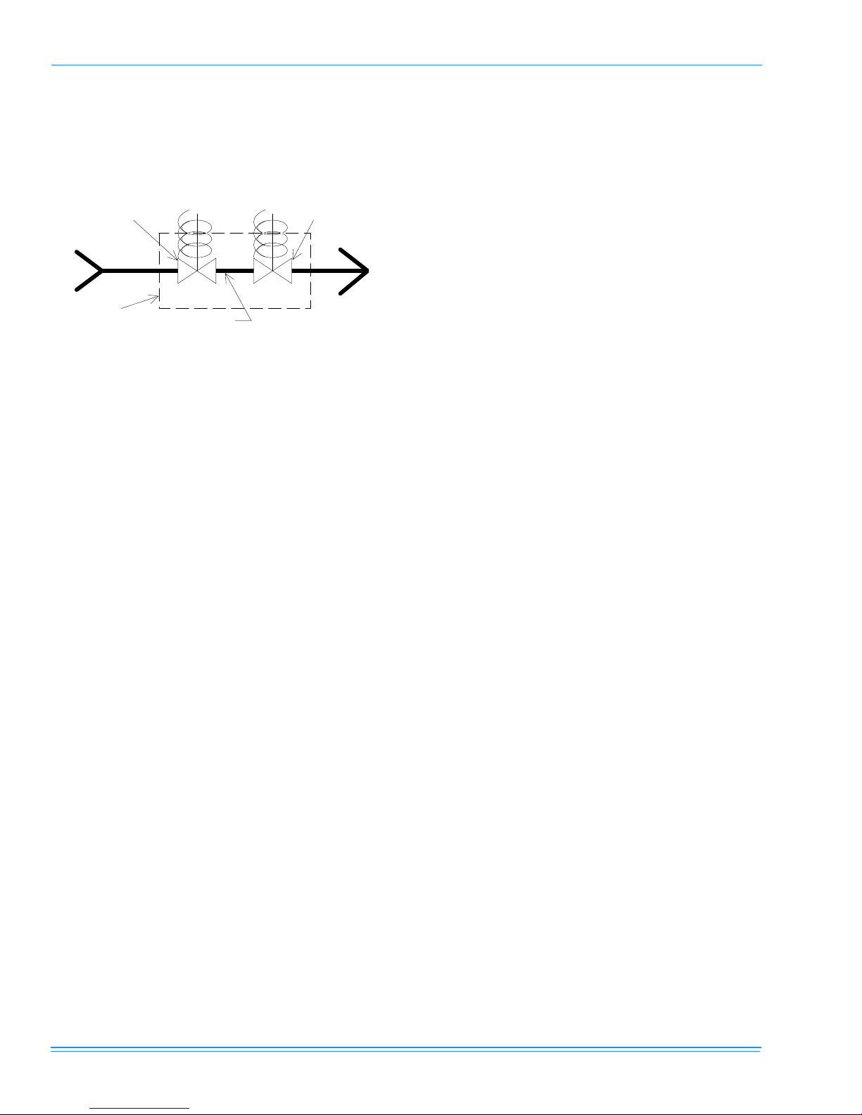
284806-YIM-A-0107
blower motor will continue to run after the furnace is
shut down until the specified fan off delay for heat ing
has been satisfied. The UCB will de-energize the
blower motor.
REDUNDANT
VALVE
GAS MAIN
GAS
VALVE
TO PILOT BURNER
MAIN VALVE
TO MAIN
BURNER
FIGURE 19 - GAS VALVE PIPING
When the thermostat calls for the first stage of heating,
the low-voltage control circuit from "R" to "W1" is completed. A call for heat passes through the UCB to the
ignition control board (ICB). The UCB monitors the
"W1" call and acts upon any call for heat. Once voltage
has been sensed at “W1”, the UCB will initiate the fan
on delay for heating, energizing the indoor blower after
the specified delay has elapsed.
When the thermostat has been satisfied, heating calls
are ceased. The GV is immediately de-energized. The
blower is de-energized after the fan off delay for heating has elapsed. The draft motor performs a 25-second
post purge.
GAS HEATING OPERATION ERRORS
TEMPERA TURE LIMIT
If the UCB senses zero volts from the high temperature
limit, the indoor blower motor is immediately energized.
When the UCB again senses 24 volts from th e tem perature limit, the draft motor will perform a 25-second
post-purge and the indoor blower will be de-energized
following the elapse of the fan off delay for heating.
This limit is monitored regardless of unit operation status, i.e. the limit is monitored at all times.
If the temperature limit opens three times within one
hour, it will lock-on the indoor blower motor and a flash
code is initiated (See Table 29).
GAS VALVE
The UCB continuously monitors the GV. Any time the
UCB senses voltage at the GV without a call for heat
for a continuous five-minute period, the UCB will lockon the indoor blower and a flash code is initiated
(Table 29). When voltage is no longer sensed at the
GV, the UCB will de-energize the indoor blower following the elapse of the fan off delay for heating.
If voltage has been sensed at the GV for at least 15
seconds during the fan on delay for heating and GV
voltage or "W1" is lost, the indoor blower is forced on
for the length of the fan off delay for heating.
SAFETY CONTROLS
The unit control board monitors the temperature limit
switch and the gas valve of gas furnace units.
The control circuit includes the following safety controls:
1. Limit Control (LS).
This control is located inside the heat exchanger
compartment and is set to open at the temperature
indicated in the Limit Control Setting Table 26. It
resets automatically. The limit switch operates
when a high temperature condition, caused by
inadequate supply air flow occurs, thus shutting
down the ignition control and closing the main gas
valves and energizing the blower.
2. Centrifugal Switc h (CS).
If the draft motor should fail, the centrifugal switch
attached to the shaft of the m otor pr even ts the ignition controls and gas valves from being energized.
3. Redundant Gas Valve.
There are two separate gas valves in the furnace.
Each valve contains a main and a redundant valve.
The redundant valves are located upstream of the
main gas valves. Should either or both of the main
gas valves fail in the open position the redundant
valves serve as back-ups and shut off the flow of
gas.
4. Flame Sensor Rod / 100% Ignition Control LockOut.
The flame rods and controls are located per Pro per
Flame Adjustment Figure 22. If an ignition control
fails to detect a signal from the flame sensor indicating the pilot flame is properly ignited, then the
main gas valve will not open. It will continue to try
and ignite the pilot for a maximum of 85 seconds,
then if the pilot flame is not detected, the ignition
control will lock out furnace operation until 24V
46 Unitary Products Group
Page 47
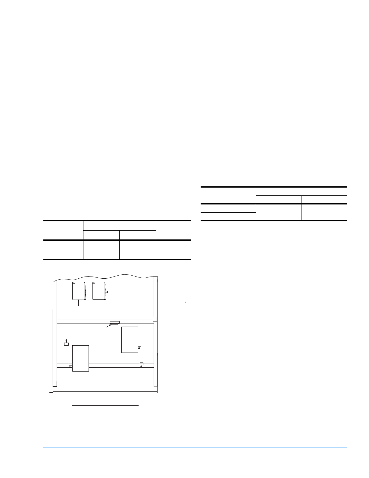
284806-YIM-A-0107
power is removed from the module either at the
unit or by resetting the room thermostat.
5. Rollout Switch.
This switch is located above the main burners in
the control compartment, which in the event of a
sustained main burner rollout shuts off and locks
out both ignition controls closing both gas valves.
The ignition controls lock out furnace operation
until 24V power is removed from the controls either
at the unit or by resetting the room thermostat.
NOTE: The a uto re set rollou t switch must reset before
allowing furnace operation.
6. Auxiliary limit switch (AUX) This control is located inside the heat exchanger
compartment and is set to open at 190°F. It is a
manual reset switch. If AUX trips, then the primary
limit has not functioned correctly. Replace the primary limit.
TABLE 26: LIMIT CONTROL SETTING
Units
(Tons)
15, 20 & 25 300 240 195
15, 20 & 25 400 320 195
Capacity, MBH
Input Output
Limit Control
Opens, ºF
FLASH CODES
The UCB will initiate a flash code associated with
errors within the system. Refer to UNIT CONTROL
BOARD FLASH CODES Table 29.
RESETS
Remove the call for heating by lowering the thermostat
setting lower than the conditioned space temperature.
This resets any flash codes.
HEAT ANTICIPATOR SETPOINTS
It is important that the anticipator setpoint be correct.
Too high of a setting will result in longer heat cycles
and a greater temperature swing in the conditioned
space. Reducing the value below the corr ect setpoint
will give shorter "ON" cycles and may result in the lowering of the temperature within the conditioned space.
TABLE 27: GAS HEAT ANTICIPATOR SETPOINTS
Gas Valve
Honeywell VR8440
White-Rodgers 36C68
Anticipator Setpoint
1st Stage 2nd Stage
0.30 amp 0.11 amp
START-UP (COOLING)
PRESTART CHECK LIST
After installation has been completed:
1. Check the electrical supply voltage being supplied.
Be sure that it is the same as listed on the unit
nameplate.
I G N . C O N T R O L # 2
2. Set the room thermostat to the off position.
3. Turn unit electrical power on.
I G N . C O N T R O L # 1
4. Set the room thermostat fan switch to on.
5. Check indoor blower rotation.
• If blower rotation is in the wrong direction.
Refer to Phasing Section in general information section.
• Check blower drive belt tension.
6. Chec k the unit supply air (CFM). See "CHECKING
SUPPLY AIR CFM" on Page 39.
S E N S O R # 1
I G N I T O R # 2
G V 2
G A S
V A L V E
R O L L O U T S W
.
G V 1
G A S
V A L V E
I G N I T O R # 1
S E N S O R # 2
7. Measure evaporator fan motor's amp draw.
8. Set the room thermostat fan switch to off.
B U R N E R C O M P A R T M E N T
9. Turn unit electrical power off.
FIGURE 20 - GAS VALVE AND CONTROLS
Unitary Products Group 47
Page 48
284806-YIM-A-0107
OPERATING INSTRUCTIONS
1. Turn unit electrical power on.
2. Set the room thermostat setting to lower than the
room temperature.
3. First stage compressors will energize after the
built-in time delay (five minutes).
4. The second stage of the thermostat will energize
second stage compressor if needed.
POST START CHECK LIST
1. Verify proper system pressures for both circuits.
2. Measure the temperature drop across the evaporator coil.
3. Measure the system Amperage draw across all
legs of 3 phase power wires.
4. Measure the condenser fan amp draw.
SHUT DOWN
1. Set the thermost at to highest temperature setting.
2. Turn off the electrical power to the unit.
START-UP (GAS HEAT)
PRE-START CHECK LIST
Complete the following checks before starting the unit.
1. Check the type of gas being supplied. Be sure that
it is the same as listed on the unit nameplate.
2. Make sure that the vent and combustion air hoods
have been properly installed.
OPERATING INSTRUCTIONS
3. Turn gas valve knob or switch to “on” position.
4. Turn “on” electric power to unit.
5. Set room thermostat to desired temperature.
(If thermostat “set” temperature is above room temperature, pilot burner ignition will occur and, after
an interval to prove pilot flame, main burners will
ignite).
TO SHUT DOWN:
1. Turn “off” electric power to unit.
2. Depress knob of gas valve while turning to “off”
position, or turn gas valve switch to “off” position.
POST-START CHECK LIST (GAS)
After the entire control circuit has been energized and
the heating section is operating, make the following
checks:
1. Check for gas leaks in the unit piping as well as the
supply piping.
FIRE OR EXPLOSION HAZARD
FAILURE TO FOLLOW THE SAFETY WARN-
ING EXACTLY COULD RESULT IN SERIOUS
INJURY, DEATH OR PROPERTY DAMAGE.
NEVER TEST FOR GAS LEAKS WITH AN
OPEN FLAME. USE A COMMERICALLY
AVAILABLE SOAP SOLUTION MADE SPECIFICALLY FOR THE DETECTION OF
LEAKS TO CHECK ALL CONNECTIONS. A
FIRE OR EXPLOSION MAY RESULT CAUSING PROPERTY DAMAGE, PERSONAL
INJURY OR LOSS OF LIFE.
This furnace is equipped with an intermittent
pilot and automatic re-ignition system. DO
NOT attempt to manually light the pilot.
TO LIGHT PILOT AND MAIN BURNERS:
1. Turn “off” electric power to unit.
2. Turn room thermostat to lowest setting.
48 Unitary Products Group
2. Check for correct manifold gas pressures. See
“Checking Gas Input” Page 49.
3. Check the supply gas pressure. It must be within
the limits shown on rating nameplate. Sup ply pres sure should be checked with all gas appliances in
the building at full fire. At no time should the
standby gas line pressure exceed 13", nor the
operating pressure drop below 5.0" for natural gas
units. If gas pressure is outside these limits, contact the local gas utility for corrective action.
Page 49
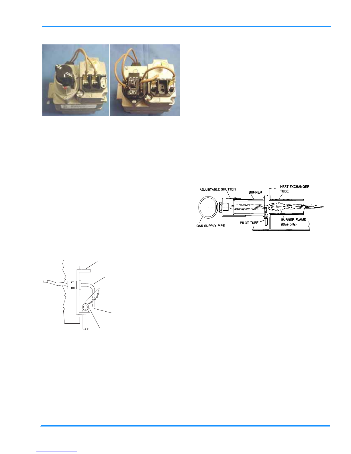
284806-YIM-A-0107
FIGURE 21 - TYPICAL GAS VALVES
MANIFOLD GAS PRESSURE ADJUSTMENT
Small adjustments to the high-fire gas flow may be
made by turning the pressure regulator adjusting screw
on the automatic gas valve.
Adjust as follows:
1. Remove the cap on the regulator. It's located next
to the push-on electrical terminals.
Put the system into operation and observe through
complete cycle to be sure all controls function properly.
BURNER INSTRUCTIONS
To check or change burners, pilot or orifices, CLOS E
MAIN MANUAL SHUT-OFF VALVE AND SHUT OFF
ALL ELECTRIC POWER TO THE UNIT.
1. Remove the screws holding either end of the manifold to the burner supports.
2. Open the union fitting in the gas supply line just
upstream of the unit gas valve and downstream
from the main manual shut-off valve.
3. Remove the gas piping closure panel.
4. Disconnect wiring to the gas valves and spark ignitors. Remove the manifold-burner gas valve
assembly by lifting up and pulling back.
2. To decrease the gas pressure, turn the adjusting
screw counterclockwise.
3. To increase the gas pressure, turn the adjusting
screw clockwise.
NOTE: The correct manifold pressure for these fur-
naces is 3.65 IWG ±0.3.
B U R N E R A S S E M B L
C A R R Y - O V E R T U B E
Y B R A C K E T
F L A M E S E N S O R B U L B
1 / 8 " G A P B E T W E E N C A R R Y - O V E R
T U B E A N D F L A M E S E N S O R B U L B
FIGURE 22 - PROPER FLAME ADJUSTMENT
PILOT CHECKOUT
The pilot flame should enve lope the end of the flame
sensor. To adjust pilot flame, (1) remove pilot adjustment cover screw, (2) increase or decrease the clearance for air to the desired level, (3) be sure to replace
cover screw after adjustment to prevent possible gas
leakage.
FIGURE 23 - TYPICAL FLAME APPEARANCE
Burners are now accessible for service.
Reverse the above procedure to replace the assem-
blies. Make sure that burners are level and seat at the
rear of the heat exchanger.
BURNER AIR SHUTTER ADJUSTMENT
Adjust burner shutters so no yellow flame is observed
in the heat exchanger tubes.
CHECKING GAS INPUT
NA TURAL GAS
1. Turn off all other gas appliances connected to the
gas meter.
2. With the furnace turned on, measure the time
needed for one revolution of the hand on the smallest dial on the meter. A typical gas meter usually
has a 1/2 or a 1 cubic foot test dial.
Unitary Products Group 49
Page 50
284806-YIM-A-0107
3. Using the number of seconds for each revolution
and the size of the test dial increment, find the
cubic feet of gas consumed per hour from the Gas
Rate - Cubic Feet Per Hour Table 28.
If the actual input is not within 5% of the furnace rating
(with allowance being made for the permissible range
of the regulator setting), replace the orifice spuds with
spuds of the proper size.
NOTE: To find the Btu input, multiply the number of
cubic feet of gas consumed per hour by the
Btu content of the gas in your particular locality
(contact your gas company for this information
- it varies widely from city to city.)
TABLE 28: GAS RATE - CUBIC FEET PER HOUR
Seconds
for One
Rev.
4
6
8
10
12
14
16
18
20
22
24
26
28
Example: By actual measurement, it takes 13 seconds for the hand on the 1cubic foot dial to make a revolution with just a 300,000 Btuh furnace running.
Read across to the column in the table above, headed “1 Cubic Foot”, where
you will see that 278 cubic feet of gas per hour are consumed by the furnace at
that rate. Multiply 278 x 1050 (the Btu rating of the gas obtained from the local
gas company). The result is 292,425 Btuh, which is close to the 300,000 Btuh
rating of the furnace.
Size of Test Dial
1/2 cu. ft. 1 cu. ft.
450
300
228
180
150
129
113
100
90
82
75
69
64
900
600
450
360
300
257
225
200
180
164
150
138
129
ADJUSTMENT OF TEMPERATURE RISE
After about 20 minutes of operation, determine the furnace temperature rise. Take readings of both the return
air and the heated air in the ducts (about six feet from
the furnace) where they will not be affected by radiant
heat. Increase
ature rise; decrease
the blower cfm to decrease the temper-
the blower cfm to increase the
rise. Refer to the Blower Motor and Drive Data
Table 23.
BELT DRIVE BLOWER
All units have belt drive single-speed blower motors.
The variable pitch pulley on the blower motor can be
adjusted to obtain the desired supply air CFM.
TROUBLESHOOTING
COOLING TROUBLESHOOTING GUIDE
Troubleshooting of components may require
opening the electrical control box with the
power connected to the unit. Use extreme
care when working with live circuits! Check
the unit nameplate for the correct line voltage
and set the voltmeter to the correct range
before making any connections with line terminals.
For troubleshooting of optional VFD, disconnect all power to the drive. Be aware that high
voltages are present in the drive even after
power has been disconnected. Capacitors
within the drive must be allowed to discharge
before beginning service.
When not necessary, shut off all electric power
to the unit prior to any of the following maintenance procedures so as to prevent personal
injury.
The temperature rise (or temperature difference
between the return air and the heated air from the furnace) must lie within the range shown on the rating
plate and the data in the Gas Heat Application Table 4.
CFM
Btuh Input x 0.8
=
o
108..xFTempRise
After the temperature rise has been determined, the
cfm can be calculated as follows:
50 Unitary Products Group
Label all wires prior to disconnection when servicing controls. Wiring errors can cause
improper and dangerous operation, which
could cause injury to person and/or damage
unit components. Verify proper op eration after
servicing.
Page 51

284806-YIM-A-0107
On calls for cooling, if the comp ressors are operating
but the supply air blower motor does not energize after
a short delay (the room thermostat fan switch is in the
“AUTO” position).
1. Turn the thermostat fan switch to the ON position.
If the supply air blower motor does not energize, g o
to Step 3.
2. If the blower motor runs with the fan switch in the
ON position but will not run after the first compressor has energized when the fan switch is in the
AUTO position, check the room thermostat for contact between R and G in the AUTO position during
calls for cooling.
3. If the supply air blower motor does not energize
when the fan switch is set to ON, check that line
voltage is being supplied to the contacts of the M3
contactor, and that the contactor is pulled in. For
units with VFD, check that line voltage is being
supplied to the M3-Auxiliary contacts. Check for
loose wiring between the contactor and the supply
air blower motor.
4. If M3 is pulled in and voltage is supplied to M3,
lightly touch the supply air blower motor housing. If
it is hot, the motor may be off on internal protection. Cancel any thermostat calls and set the fan
switch to AUTO. Wait for the internal overload to
reset. Test again when cool.
5. If M3 is not pulled in, check for 24 volts at the M3
coil. If 24 volts are present at M3 but M3 is not
pulled in, replace the contactor.
6. Failing the above, if there is line voltage supplied at
M3, M3 is pulled in, and the supply air blower
motor still does not operate, replace the motor.
For units with VFD, if there is line voltage supplied
at M3, M3 is pulled in, and the blower motor does
not operate, check all power & control wiring connections to and from the drive and for any fault/
warning messages displayed on the drive's digital
display (refer to the drive user manual for full
descriptions, if necessary). Clear any fault by
pressing 'RESET' on the drive's keypad and take
any corrective action as needed. If the motor still
does not operate, replace the motor.
7. If 24 volts is not present at M3, check that 24 volts
is present at the UCB supply air blower motor terminal, “FAN”. If 24 volts is present at the FAN,
check for loose wiring between the UCB and M3.
8. If 24 volts is not present at the “FAN” terminal,
check for 24 volts from the room thermostat. If 24
volts are not present from the room thermostat,
check for the following:
a. proper operation of the room thermostat (contact
between R and G with the fan switch in the ON position and in the AUTO position during operation
calls), b. proper wiring between the room thermostat
and the UCB, and c. loose wiring from the room
thermostat to the UCB.
9. If 24 volts is present at the room thermostat but not
at the UCB, check for proper wiring between the
thermostat and the UCB, i.e. that the thermostat G
terminal is connected to the G terminal of the UCB,
and for loose wiring.
10. If the thermostat and UCB are properly wired,
replace the UCB.
On calls for cooling, the supply air blower motor is
operating but compressor #1 is not (the room thermostat fan switch is in the “AUTO” position).
1. If installed, check the position of the economizer
blades. If the blades are open, the economizer is
providing free cooling and the compressors will not
immediately operate. If both stages of cooling are
requested simultaneously and the economizer provides free cooling, following a short delay compressor #1 will be energized unless it is locked out. If
compressor #1 is locked out, compressor #2 is
energized. Compressor #2 is always energized in
place of compressor #1 when compressor #1 is
requested but locked out.
2. If no economizer is installed or the economizer is not
opening to provide free cooling and compressor #1
does not energize on a call for cooling, check for line
voltage at the compressor contactor, M1, and that
the contactor is pulled in. Check for loose wiring
between the contactor and the compressor .
3. If M1 is pulled in and voltage is supplied at M1,
lightly touch the compressor housing. If it is hot, the
compressor may be off on inherent protection.
Cancel any calls for cooling and wait for the internal overload to reset. Test again when cool.
4. If M1 is not pulled in, check for 24 volts at the M1
coil. If 24 volts are present and M 1 is not pu lled in,
replace the contactor.
5. Failing the above, if voltage is supplied at M1, M1
is pulled in, and the compressor still does not operate, replace the compressor.
6. If 24 volts is not present at M1, check for 24 volts at
the UCB terminal, C1. If 24 volts is present, check
for loose wiring between C1 and the compressor
contactor.
Unitary Products Group 51
Page 52

284806-YIM-A-0107
7. If 24 volts is not present at the C1 terminal, check
for 24 volts from the room thermostat at the UCB
Y1 terminal. If 24 volts is not present from the room
thermostat, check for the following:
a. 24 volts at the thermostat Y1 terminal
b. Proper wiring between the room thermostat and the
UCB, i.e. Y1 to Y1, Y2 to Y2
c. Loose wiring from the room thermostat to the UCB.
8. If 24 volts is present at the UCB Y1 terminal, the
compressor may be out due to an open high-pressure switch, low-pressure switch, or freezestat.
Check for 24 volts at the HPS1, LPS1, and FS1
terminals of the UCB. If a switch has opened, there
should be a voltage potential between the UCB terminals, e.g. if LPS1 has opened, there will be a 24volt potential between the LPS1 terminals.
9. If 24 volts is present at the UCB Y1 terminal and
none of the protection switches have opened, the
UCB may have locked out the compressor for
repeat trips. The UCB should be flashing an alarm
code. If not, press and release the ALARMS button
on the UCB. The UCB will flash the last five alarms
on the LED. If the compressor is locked out, cancel
any call for cooling. This will reset any compressor
lock outs.
NOTE: While the above step will reset any lockouts,
compressor #1 may be held off for the ASCD.
See the next step.
10. If 24 volts is present at the UCB Y1 terminal and
none of the switches are open and the compressor
is not locked out, the UCB may have the compressor in an ASCD. Check the LED for an indication of
an ASCD cycle. The ASCD should time out within
5 minutes. Press and release the TEST button to
reset all ASCDs.
11. If 24 volts is present at the UCB Y1 terminal and
the compressor is not out due to a protective
switch trip, repeat trip lock out, or ASCD, the economizer terminals of the UCB may be improperly
wired. Check for 24 volts at the Y1 “OUT” terminal
of the UCB. If 24 volts is present, trace the wiring
from Y1 “OUT” for incorrect wiring. If 24 volts is not
present at the Y1 “OUT” terminal, the UCB must be
replaced.
12. For units without economizers:If 24 volts is present
at the Y1 OUT terminal, check for 24 volts at the
Y1 “ECON” terminal. If 24 volts is not present,
check for loose wiring from the Y1 “OUT” terminal
to the Mate-N-Lock plug, the jumper in the Mate-N -
Lock plug, and in the wiring from the Mate-N-Lock
plug to the Y1 “ECON” terminal.
13. For units with economizers: If 24 volts is present at
the Y1 “OUT” terminal, check for 24 volts at the Y1
“ECON” terminal. If 24 volts is not present, check
for loose wiring from the Y1 “OUT” terminal to the
Mate-N-Lock plug, a poor connection between the
UCB and economizer Mate-N-Lock plugs, loose
wiring from the Mate-N-Lock plug to the economizer, back to the Mate-N-Lock plug, and from the
Mate-N-Lock plug to the Y1 “ECON” terminal. If
nothing is found, the economizer DME may have
faulted and is failing to return the 24-volt “call” to
the Y1 “ECON” terminal even though the economizer is not providing free cooling. To test, disconnect the Mate-N-Locks and jumper between the
WHITE and YELLOW wires of the UCB’s Mate-NLock plug. If compressor #1 energizes, the re is a
fault in the economizer wiring or DME.
14. The UCB can be programmed to lock out compressor operation during free cooling and in low ambient conditions. These options are not enabled by
default. Local distributors can test the UCB fo r this
programming.
For units with factory installed economizers, the
UCB is programmed to lock out compressor operation when the LAS set point is reached.
For units without factory installed or with field
installed economizers, the UCB allows compressor
operation all the time. This programming can be
checked or changed by the local distributor.
15. If none of the above corrected the error, test the
integrity of the UCB. Disconnect the C1 terminal
wire and jumper it to the Y1 terminal. DO NOT
jump the Y1 to C1 terminals. If the compressor
engages, the UCB has faulted.
16. If none of the above correct the error, replace the
UCB.
On calls for the second stage of cooling, the supply air
blower motor and compressor #1 are operating but
compressor #2 is not (the room thermostat fan switch
is in the “AUTO” position).
1. If installed, check the position of the economizer
blades. If the blades are open, the economizer is
providing free cooling. If the second stage of
cooling is requested, following a short delay,
compressor #1 will be energized unless it is locked
out. Typically, compressor #2 is energized only
52 Unitary Products Group
Page 53

284806-YIM-A-0107
during free cooling if the call for the second stage
of cooling persists for 20 minutes.
2. Compressor #2 will not energize simultaneously
with compressor #1 if a call for both stages of cooling is received. The UCB delays compressor #2 by
30 seconds to prevent a power surge. If after the
delay compressor #2 does not energize on a second stage call for cooling, check for line voltage at
the compressor contactor, M2, and that the contactor is pulled in. Check for loose wiring between the
contactor and the compressor.
3. If M2 is pulled in and voltage is supplied at M2,
lightly touch the compressor housing. If it is hot, the
compressor may be off on inherent protection.
Cancel any calls for cooling and wait for the internal overload to reset. Test again when cool.
4. If M2 is not pulled in, check for 24 volts at the M2
coil. If 24 volts is present and M2 is not pulled in,
replace the contactor.
5. Failing the above, if voltage is supplied at M2, M2
is pulled in, and the compressor still does not operate, replace the compressor.
6. If 24 volt s is not present at M2, che ck for 24 volt s at
the UCB terminal, C2. If 24 volts are present,
check for loose wiring between C2 and the compressor contactor.
7. If 24 volts is not present at the C2 terminal, check
for 24 volts from the room thermostat at the UCB
Y2 terminal. If 24 volts is not present from the room
thermostat, check for the following:
a. 24 volts at the thermostat Y2 terminal
b. Proper wiring between the room thermostat and the
UCB, i.e. Y1 to Y1, Y2 to Y2
c. Loose wiring from the room thermostat to the UCB.
8. If 24 volts is present at the UCB Y2 terminal, the
compressor may be out due to an open high-pressure switch, low-pressure switch, or freezestat.
Check for 24 volts at the HPS2, LPS2, and FS2
terminals of the UCB. If a switch has opened, there
should be a voltage potential between the UCB terminals, e.g. if LPS2 has opened, there will be 24
volts of potential between the LPS2 terminals.
9. If 24 volts is present at the UCB Y2 terminal and
none of the protection switches have opened, the
UCB may have locked out the compressor for
repeat trips. The UCB should be flashing a co de. I f
not, press and release the ALARMS button on the
UCB. The UCB will flash the last five alarms on the
LED. If the compressor is locked out, remove any
call for cooling at the thermostat or by disconnecting the thermostat wiring at the Y2 UCB terminal.
This will reset any compressor lock outs.
NOTE: While the above step will reset any lock outs,
compressor #1 will be held off for the ASCD,
and compressor #2 may be held off for a portion of the ASCD. See the next step.
10. If 24 volts is present at the UCB Y2 terminal and
none of the switches are open and the compressor
is not locked out, the UCB may have the compressor in an ASCD. Check the LED for an indication of
an ASCD cycle. The ASCD should time out within
5 minutes. Press and release the TEST button to
reset all ASCDs.
1 1. The UCB can be programmed to lock out compres-
sor operation during free cooling and in low ambient conditions. These options are not enabled by
default. Local distributors can test the UCB fo r this
programming.
For units with factory installed economizers, the
UCB is programmed to lock out compressor operation when the LAS set point is reached.
For units without factory installed or with field
installed economizers, the UCB allows compressor
operation all the time. This programming can be
checked or changed by the local distributor.
12. If none of the above corrected the error, test the
integrity of the UGB. Disconnect the C2 terminal
wire and jumper it to the Y2 terminal. DO NOT
jump the Y2 to C2 terminals. If the compressor
engages, the UCB has faulted.
13. If none of the above correct the error, replace the
UCB.
On a call for cooling, the supply air blower motor and
compressor #2 are operating but compressor #1 is not
(the room thermostat fan switch is in the “AUTO” position).
1. Compressor #2 is energized in place of compressor #1 when compressor #1 is unavailable for cooling calls. Check the UCB for alarms indicating that
compressor #1 is locked out. Press and release
the ALARMS button if the LED is not flashing an
alarm.
2. Check for line voltage at the compressor contactor,
M1, and that the contactor is pulled in. Check for
loose wiring between the contactor and the compressor.
Unitary Products Group 53
Page 54

284806-YIM-A-0107
3. If M1 is pulled in and voltage is supplied at M1,
lightly touch the compressor housing. If it is hot, the
compressor may be off on inherent protection.
Cancel any calls for cooling and wait for the internal overload to reset. Test again when cool.
4. If M1 is not pulled in, check for 24 volts at the M1
coil. If 24 volts is present and M1 is not pulled in,
replace the contactor.
5. Failing the above, if voltage is supplied at M1, M1
is pulled in, and the compressor still does not operate, replace the compressor.
6. If 24 volts is not present at M1, check for 24 volts at
the UCB terminal, C1. If 24 volts is present, check
for loose wiring between C1 and the compressor
contactor.
7. If 24 volts is not present at the C1 terminal, check
for 24 volts from the room thermostat at the UCB
Y1 terminal. If 24 volts are not present at the UCB
Y1 terminal, the UCB may have faulted. Check for
24 volts at the Y1 ECON terminal. If 24 volts is not
present at Y1 “ECON”, the UCB has faulted. The
UCB should de-energize all compressors on a loss
of call for the first stage of cooling, i.e. a loss if 24
volts at the Y1 terminal.
8. If 24 volts are present at the UCB Y1 terminal, the
compressor may be out due to an open high-pressure switch, low-pressure switch, or freezestat.
Check for 24 volts at the HPS1, LPS1, and FS1
terminals of the UCB. If a switch has opened, there
should be a voltage potential between the UCB terminals, e.g. if LPS1 has opened, there will be a 24volt potential between the LPS1 terminals.
9. If 24 volts is present at the UCB Y1 terminal and
none of the protection switches have opened, the
UCB may have locked out the compressor for
repeat trips. The UCB should be flashing a code . If
not, press and release the ALARMS button on the
UCB. The UCB will flash the last five alarms on the
LED. If the compressor is locked out, remove any
call for cooling. This will reset any compressor lock
outs.
NOTE: While the abov e step will reset any lock outs,
compressor #2 will be held off for the ASCD,
and compressor #1 may be held off for a portion of the ASCD. See the next step.
10. If 24 volts is present at the UCB Y1 terminal and
none of the switches are open and the compressor
is not locked out, the UCB may have the compressor in an ASCD. Check the LED for an indication of
an ASCD cycle. The ASCD should time out within
5 minutes. Press and release the TEST butt on to
reset all ASCDs.
11. If 24 volts is present at the UCB Y1 terminal and
the compressor is not out due to a protective
switch trip, repeat trip lock out, or ASCD, the economizer terminals of the UCB may be improperly
wired. Check for 24 volts at the Y1 “OUT” terminal
of the UCB. If 24 volts is present, trace the wiring
from Y1 “OUT” for incorrect wiring. If 24 volts is not
present at the Y1 “OUT” terminal, the UCB must be
replaced.
12. For units without economizers: If 24 volts is present
at the Y1 “OUT” terminal, check for 24 volts at the
Y1 “ECON” terminal. If 24 volts is not present,
check for loose wiring from the Y1 “OUT” termin al
to the Mate-N-Lock plug, the jumper in the Mate-NLock plug, and in the wiring from the Mate-N-Lock
plug to the Y1 “ECON” terminal.
For units with economizers: If 24 volts is present at
the Y1 “OUT” terminal, check for 24 volts at the Y1
“ECON” terminal. If 24 volts is not present, check
for loose wiring from the Y1 “OUT” terminal to the
Mate-N-Lock plug, a poor connection between the
UCB and economizer Mate-N-Lock plugs, loose
wiring from the Mate-N-Lock plug to the
economizer, back to the Mate-N-Lock plug, and
from the Mate-N-Lock plug to the Y1 “ECON”
terminal. The economizer board may have faulted
and is not returning the 24 volts to the Y1 “ECON”
terminal even though the economizer is not
providing free cooling. To test the economizer
board, disconnect the Mate-N-Locks and jumper
between the WHITE and YELLOW wires of the
UCB’s Mate-N-Lock plug.
13. The UCB can be programmed to lock out compressor operation during free cooling and in low ambient conditions. These options are not enabled by
default. They can be checked by local distributors.
For units with factory installed economizers, the
UCB is programmed to lock out compressor operation when the LAS set point is reached.
For units without factory installed or with field
installed economizers, the UCB allows compressor
operation all the time. This programming can be
checked or changed by the local distributor.
54 Unitary Products Group
Page 55
284806-YIM-A-0107
14. If none of the above corrected the error, test the
integrity of the UCB. Disconnect the C1 terminal
wire and jumper it to the Y1 terminal. DO NOT
jump the Y1 to C1 terminals. If the compressor
engages, the UCB has faulted.
15. If none of the above correct the error, replace the
UCB.
GAS HEAT TROUBLESHOOTING GUIDE
Troubleshooting of components may require
opening the electrical control box with the
power connected to the unit. Use extreme care
when working with live circuits! Check the
unit nameplate for the correct line voltage and
set the voltmeter to the correct range before
making any connections with line terminals.
For troubleshooting of optional VFD, disconnect all power to the drive. Be aware that high
voltages are present in the drive even after
power has been disconnected. Capacitors
within the drive must be allowed to discharge
before beginning service.
When not necessary, shut off all electric power to
the unit prior to any of the following maintenance
procedures so as to prevent personal injury.
Label all wires prior to disconnection when servicing controls. Wiring errors can cause
improper and dangerous operation, which could
cause injury to person and/or damage unit components. Verify proper operation after servicing.
NOTE: To find the Btu input, multiply the number of
cubic feet of gas consumed per hour by the
Btu content of the gas in your particular locality
(contact your gas company for this information
- it varies widely from city to city.).
The furnace may shut down on a high temperature condition during the procedure. If this
occurs, the UCB energize the supply air blower
motor until the high temperature limit has reset.
Caution should be used at all times as the supply air blower may energize regardless of the
room thermostat fan switch position.
On calls for heating, the draft motor operates and the
furnace lights but the supply air blower motor does not
energize after a short delay (the room thermostat fan
switch is in “AUTO” position).
1. Place the thermostat fan switch in the “ON” position. If the supply air blower moto r en ergiz es , go t o
Step 10.
2. If the supply air blower motor does not energize
when the fan switch is set to “ON,” check that line
voltage is being supplied to the contacts of the M3
contactor, and that the contactor is pulled in. For
units with VFD, check that line voltage is being
supplied to the M3-Auxiliary contacts. Check for
loose wiring between the contactor and the supply
air blower motor.
3. If M3 is pulled in and voltage is supplied at M3,
lightly touch the supply air blower motor housing. If
it is hot, the motor may be off on inherent protection. Cancel any thermostat calls and set the fan
switch to “AUTO”, wait for the internal overload to
reset. Test again when cool.
4. If M3 is not pulled in, check for 24 volts at the M3
coil. If 24 volts is present at M3 but M3 is not pulled
in, replace the contactor.
5. Failing the above, if there is line voltage supplied at
M3, M3 is pulled in, and the supply air blower
motor still does not operate, replace the motor.
For units with VFD, if there is line voltage supplied
at M3, M3 is pulled in, and the blower motor does
not operate, check all power & control wiring connections to and from the drive and for any fault/
warning messages displayed on the drive's digital
display (refer to the drive user manual for full
descriptions, if necessary). Clear any fault by
pressing 'RESET' on the drive's keypad and take
any corrective action as needed. If the motor still
does not operate, replace the motor.
Unitary Products Group 55
Page 56

284806-YIM-A-0107
6. If 24 volts is not present at M3, check that 24 volts
is present at the supply air blower motor terminal on
the UCB. If 24 volts is present at the UCB terminal,
check for loose wiring between the UCB and M3.
7. If 24 volts is not present at the UCB supply air
blower motor terminal, check for 24 volts from the
room thermostat. If 24 volts is not present from the
room thermostat, check for the following:
a. Proper operation of the room thermostat (contact
between R and G with the fan switch in the “ON”
position and in the “AUTO” position during operation
calls).
b. Proper wiring between the room thermostat and the
UCB.
c. Loose wiring from the room thermostat to the UCB.
8. If 24 volts is present at the room thermostat but not
at the UCB, check for proper wiring between the
thermostat and the UCB, i.e. that the thermostat G
terminal is connected to the G terminal of the UCB,
and for loose wiring.
9. If the thermostat and UCB are properly wired,
replace the UCB.
10. If the blower motor runs with the fan switch in the
“ON” position but does not run shortly after the furnace has ignited when the fan switch is in the
“AUTO” position, check the room thermostat for
contact between R and G during “W1” calls.
On calls for heating, the supply air blower operates but
the draft motor does not (the room thermostat fan
switch is in the “AUTO” position).
1. The draft motor has inherent protection. If the
motor shell is hot to the touch, wait for the internal
overload to reset.
2. If the motor shell is cold with the room thermostat
calling for heat, check for line voltage at the
motor's Mate-N-Lok connector attached to the
evaporator partition. If line voltage is present,
replace the draft motor.
3. If line voltage is not present, check for line voltage
at the heat relay (RW1) contacts in the main control box and check to see if the (RW1) is pulled in.
4. If the (RW1) relay is pulled in, check for a loose line
voltage connection.
5. If the (RW1) relay is not pulled in, check for 24 volt s
at the (RW1) coil. If 24 volts is present, replace the
(RW1) relay. If 24 volts is not present, check for a
loose 24 volt connection back to the relay board
and check the connections from the room thermostat to the relay board. If all connections are correct, replace the relay board.
The draft motor runs but the furnace does not light and
the sparker does not spark.
1. The ignition control (IC1, IC2) may be locked out
due to either a flame roll out or 100% shut off.
These safety features are described above. If lockout has occurred, 24V must be removed from the
ignition controls. This is done at the unit or by
resetting the room thermostat. After resetting 24V,
check for proper furnace operation. If lock-out continues to occur, locate the source of the problem
and correct.
2. Check all 24 volt connections from the relay board
to and in the gas heat section. Check low voltage
connections to the (ETD) located in the control
box.
3. If the furnace is hot, it may be out on an over-temperature condition, wait for limit reset.
4. If the furnace is cold, check for 24 volts at wire 241
attached to the electrical time delay (ETD) located
in the main control box. If 24 volts is not found,
replace the ETD.
5. 24 volts is found at wire 241, remove the wires
attached to the (TDR) and with a VOM, check for
continuity across contacts 1 and 2. If none is found,
the (TDR) is open and must be replaced. If there is
continuity, re-attach the wires.With the draft motor
running, check for 24 volts at terminal 4 of (RW1-2)
and (RW2-1). If 24 volts is not present, the centrifugal switch (CS) has not closed or has gone bad.
Check the line voltage to the unit - if it is correct,
replace the draft motor. If line voltage is low, call
the power company.
6. Check for 24V at terminal 2 of (RW1-2 and RW2-
1). If 24V is not present, check for 24V at (RW1
and RW2) relay coils. If these relays are pulled in,
then check for a loose connection at terminal 2 and
terminal 4 of each relay. If no problem is found,
then replace (RW1 and/or RW2) as required.
7. If 24 volts is present at the ignitor controls, check
all control wiring at the ignitor controls and the high
tension wire to the ignitors. Check that the ground
wires from the ignitor controls, the gas valves and
pilot burners are all intact and making good electrical connection. Check to make sure that the
ceramic insulator on the pilot ignitor s or sensors is
not broken or cracked, if all are intact, replace the
ignition control IC1 or IC2.
The draft motor runs and the ignitor sparks at the pilot
burner but the pilot does not ignite and a gas odor is
not detected at the draft motor outlet.
56 Unitary Products Group
Page 57

284806-YIM-A-0107
1. Check to make sure gas is being supplied to the
unit. Make sure that the gas pressure to the unit is
within the proper limits as described in the “POST
START CHECK LIST” Page 48 and that the pilot
adjust screw is allowing some flow of gas as
described in “PILOT CHECKOUT” Page 49.
2. Check all wiring between the ignitor control and the
gas valve. Check to make sure the ground connections are intact.
3. If the wiring is intact, check for 24 volts across terminals “PV” and “COMMON” on the ignit or control.
If 24 volts is not present, replace the ignitor con trol.
4. If 24 volts is present, remove the pilot burner and
remove the pilot orifice from the pilot burner. The
orifice is removed in the direction opposite the flow
of gas. Inspect the orifice for obstruction. If it is
clear, replace the main gas valve.
The ignitor sparks at the pilot burner but the pilot does
not ignite and a gas odor is detected at the draft motor
outlet.
1. Adjust the pilot adjust screw on the gas valve as
described in “PILOT CHECKOUT” Page 49.
2. Check the supply pressure as described in “POST
START CHECK LIST” Page 48. Make adjustments
as necessary.
3. Check the pilot orifice for obstruction as described
in paragraph above. Clean as needed but the problem should not be the gas valve.
The pilot burner ignites but the ignitor continues to
spark and the main burners do not ignite.
1. Make the same checks and adjustment as
described in “PILOT CHECKOUT” Page 49.
2. Check the supply pressure as described in “POST
START CHECK LIST” Page 48. Make adjustments
as necessary.
3. Make sure that the pilot burner is not bent or damaged.
4. Make sure that the ground connections at the pilot
burner, gas valve and ignitor control are intact.
Check the high tension wire for good electrical connection. If all are intact, replace the ignitor module.
The pilot burner lights and the spark stops but the main
burners do not light.
1. Check electrical connections between the ignitor
control and the gas valve. If intact, check for 24
volts across terminals “MV” and “COMMON” terminals. If no voltage detected, replace ignitor control.
If voltage is present, replace gas valve.
Furnace lights with roll-out or one burner has delayed
ignition.
1. Make sure that the pilot burner is aligned properly
with the carryover as described in “PILOT CHECKOUT” Page 49.
2. Make sure that the carryovers on adjoining burners
are screwed fast and are lev el with respect to one
another.
Main burners light but exhibit erratic flame characteristics.
1. Adjus t air shutters as described in “BURNER AIR
SHUTTER ADJUSTMENT” Page 49.
2. Check the main burner orifices for obstruction and
alignment. Removal procedure is described in
BURNER INSTRUCTIONS Page 49. Clean or
replace burner orifices and burners as needed.
UNIT CONTROL BOARD FLASH CODES
Various flash codes are utilized by the unit control
board (UCB) to aid in troubleshooting. Flash codes are
distinguished by the short on and off cycle used
(approximately 200ms on and 200ms off). To show
normal operation, the control board flashes a 1 second
on, 1 second off "heartbeat" during normal operation.
This is to verify that the UCB is functioning correctly.
Do not confuse this with an error flash code. To prevent
confusion, a 1-flash, flash code is not used.
Alarm condition codes are flashed on the UCB lower
left Red LED, See Figure 24. While the alarm cod e is
being flashed, it will also be shown by the other LEDs:
lit continuously while the alarm is being flashed. The
total of the continuously lit LEDs equates to the number
of flashes, and is shown in the table. Pressing and
releasing the LAST ERROR button on the UCB can
check the alarm history. The UCB will cycle through the
last five (5) alarms, most recent to oldest, separating
each alarm flash code by approximately 2 seconds. In
all cases, a flashing Green LED will be used to indicate
non-alarm condition.
In some cases, it may be necessary to "zero" the
ASCD for the compressors in order to perform troubleshooting. To reset all ASCDs for one cycle, press and
release the UCB TEST/ RESET button once.
Flash codes that do and do not represent alarms are
listed in Table 29.
Unitary Products Group 57
Page 58
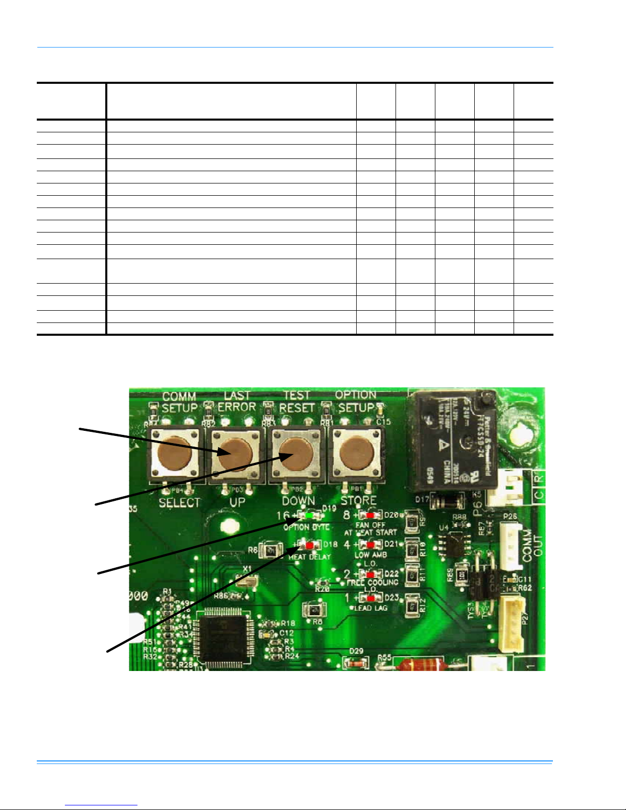
TABLE 29: UNIT CONTROL BOARD FLASH CODES
284806-YIM-A-0107
RED
LED
2
FLASH CODE DESCRIPTION
GREEN
LED
16
RED
LED
8
RED
LED
4
On Steady This is a Control Failure - - - - -
1 Flash Not Applicable - - - - -
2 Flashes
Control waiting ASCD
1
Flashing Off Off On Off
3 Flashes HPS1 Compressor Lockout Off Off Off On On
4 Flashes HPS2 Compressor Lockout Off Off On Off Off
5 Flashes LPS1 Compressor Lockout Off Off On Off On
6 Flashes LPS2 Compressor Lockout Off Off On On Off
7 Flashes FS1 Compressor Lockout Off Off On On On
8 Flashes FS2 Compressor Lockout Off On Off Off Off
9 Flashes Ignition Control Locked Out / Ignition Control Failure Off On Off Off On
10 Flashes
11 Flashes
Compressors Locked Out on Low Outdoor Air Temperature
1
Compressors locked out because the Economizer is using free
1
Cooling
Flashing On Off On Off
Flashing On Off On On
12 Flashes Unit Locked Out due to Fan Overload Switch Failure Off On On Off Off
13 Flashes
Compressor Held Off due to Low Voltage
1
Flashing On On Off On
14 Flashes EEPROM Storage Failure Off On On On Off
OFF No Power or Control Failure Off Off Off Off Off
1.
Non-alarm condition.
RED
LED
1
Check
Alarm
History
Reset All
ASCDs for
One Cycle
Non Alarm
Condition Green
LED Flashing
Current Alarm
Flashed
Red LED
FIGURE 24 - UNIT CONTROL BOARD
58 Unitary Products Group
Page 59
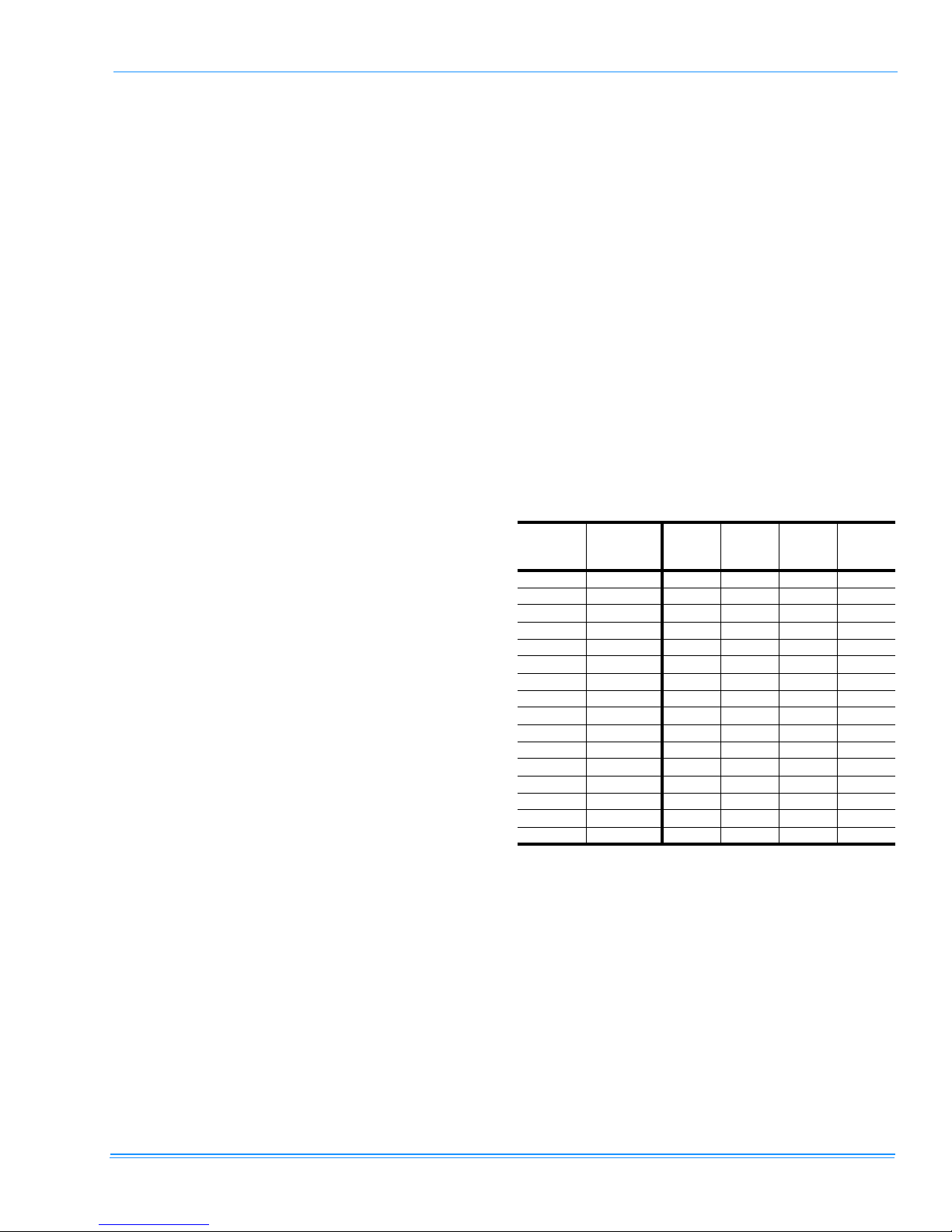
284806-YIM-A-0107
UNIT CONTROL BOARD OPTION SETUP
OPTION BYTE SETUP
• Enter the Option Setup mode by pushing the
OPTION SETUP / STORE button, and holding it for
at least 2 seconds.
• The green status LED (Option Byte) will be turned
on and the red status LED (Heat Delay) is turned
off.
• The 8, 4, 2 and 1 LEDs will then show the status of
the 4 labeled options ((8) Fan Off at Heat St art, (4)
Low Ambient Lockout, (2) Free Cooling Lockout, and (1) Lead / Lag).
• Press the UP or Down button to change the LED
status to correspond to the desired Option Setup.
• To save the current displayed value, push the
OPTION SETUP / STORE button and hold it for at
least 2 seconds. When the value is saved, the
green LED will flash a few times and then normal
display will resume.
NOTE: While in either Setup mode, if no buttons are
pushed for 60 seconds, the display will revert
to its normal display, exiting the Option Setup
mode. When saving, the control board only
saves the parameters for the currently displayed mode (Option Byte or Heat Delay).
HEAT DELAY SETUP
• Enter the Option Setup mode by pushing the
OPTION SETUP / STORE button, and holding it for
at least 2 seconds.
• The green status LED (Option Byte) will be turned
on and the red status LED (Heat Delay) is turned
off.
• Press the COMM SETUP / SELECT button to toggle into the Heat Delay Setup, the green LED will
turn off and the red LED for Heat Delay will turn on.
• The 8, 4, 2 and 1 LEDs will then show the status of
the Heat Delay, (See Table 30). Press the UP or
Down button to change the LED status to correspond to the desired Heat Delay Value.
• To save the current displayed value, push the
OPTION SETUP / STORE button and hold it for at
least 2 seconds. When the value is saved, the red
LED will flash a few times and then normal display
will resume.
NOTE: While in either Setup mode, if no buttons are
pushed for 60 seconds, the display will revert
to its normal display, exiting the Option Setup
mode. When saving, the control board only
saves the parameters for the currently displayed mode (Option Byte or Heat Delay).
TABLE 30: HEAT DELAY
Heat
Fan On
Delay
60 180 On On On On
60 90 On On On Off
60 60 On On Off On
60 30 On On Off Off
45 180 On Off On On
45 90 On Off On Off
45 60 On Off Off On
45 30 On Off Off Off
30 180 Off On On On
30 90 Off On On Off
30 60 Off On Off On
30 30 Off On Off Off
060OffOffOnOn
0 30 Off Off On Off
0 10 Off Off Off On
Non-std Non-std Off Off Off Off
Heat
Fan Off
Delay
Red
LED 8
Red
LED 4
Red
LED 2
Red
LED 1
Unitary Products Group 59
Page 60

Subject to change without notice. Printed in U.S.A. 284806-YIM-A-0107
Copyright © 2007 by Unitary Products Group. All righ ts reserved. Supersedes: 175233-YIM-A-0706
Unitary 5005 Norman
Products York OK
Group Drive 73069
 Loading...