

Sunjet ZLHW-3T250DF, ZLHW-3T200DF, ZLHW-3T300DF, ZLHW-3T150DF User Manual
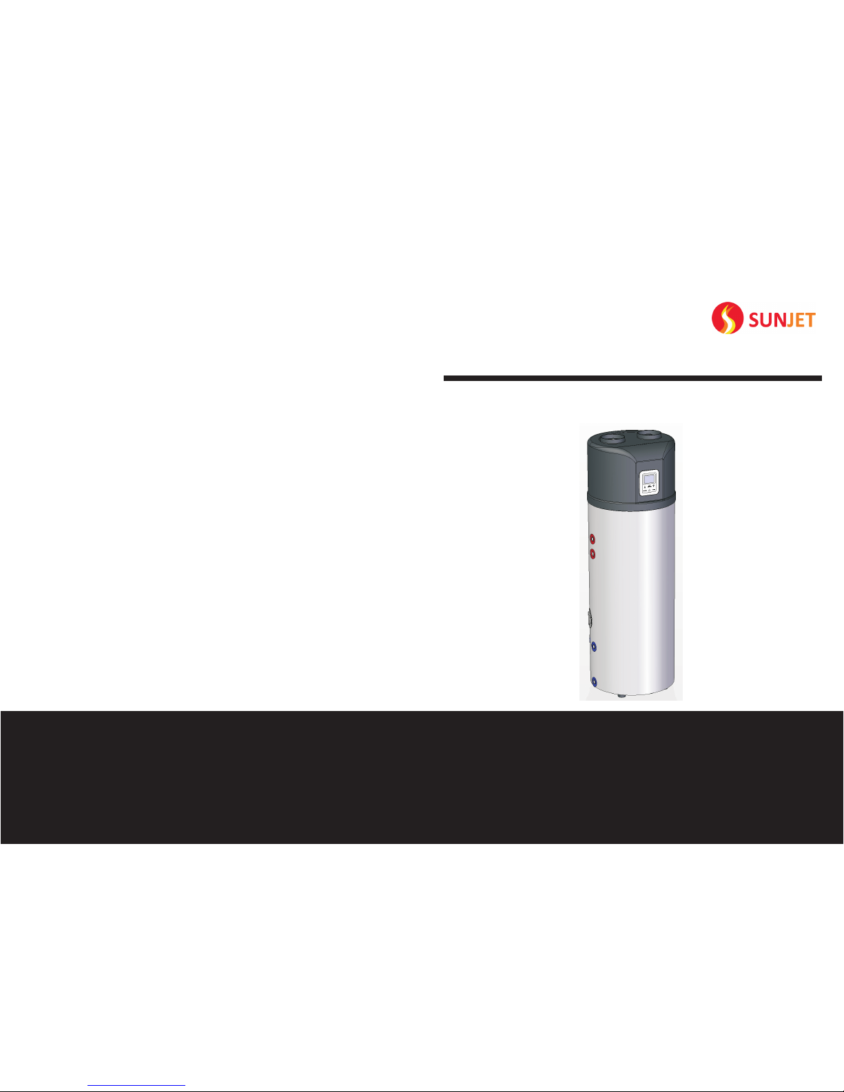
Domestic Hot Water Heat Pump
User Manual
MODEL:
ZLHW-3T150DF
ZLHW-3T200DF
ZLHW-3T250DF
ZLHW-3T300DF
Please Prop erly Keep thi s Manual.
Please Care fully Read th is Manual Bef ore Using t he H eat Pump.
THANKS FOR
YOUR CHOICE


Content
1. Safety Precautions
2. Specifications
4. Installation
3. Structure
6. Operation and performance
5. Controller
7. Maintenance and trouble shooting
8. Wiring Diagram
1
3
4
5
12
17
18
21
Note
22
Note
Domestic Ho t Wat er Heat Pump
23
1. Safety Precautions
Domestic Ho t Wat er Heat Pump
1
The aim of this manual is to provide instructi ons f or in sta lla tio n, co mmi ssi oni ng, o per ati on.
T he i ns ta ll at io n, c om mi ssi on in g a nd
maintenance o f the se machines sho uld
be p er fo rmed by q ua li fi ed pe rs on ne l
having a good kn owl edg e of standards
and local regulations, as well as experience
of this type of equipment.
WARNING!
The unit should be handled using lifting
and handing equipment appropriate to the
unit’s s ize a nd we igh t.
TAKE CAR E!
WARNING!
Any wiring produced on site must comply with
local electrical regulations.
It is forbidden to sta rt any work on the
electrical components without switching
off t he el ect ric al su ppl y to th e uni t.
TAKE CAR E!
When the unit is being connected, ensure
that n o im pur iti es are int rod uce d in to the
pipe work and the water circuits.
TAKE CAR E!
A mes h file r must be pr ovi ded on the
hydraulic pump and in exchanger water
inlets.
TAKE CAR E!
Ensure that the electrical supply corres pon ds
to t he s pec ifi cat ion indicated on t he u nit ’s
maker ’s p lat e before p roc eed ing wi th t he
connection in ac cor dan ce w ith the wi rin g
diagram supplied.
WARNING!
WARNING!
The unit must be EARTHE D to av oid a ny ri sks
caused by insulation defects.
No wiring must come in contact with the heat
source or the fan rotating parts.
WARNING!
Preparation for shut tin g dow n the uni t for a
prolonged p eri od if the i nst all ati on doe s n ot
contain glycol, the evaporator and the chilled
wa ter pi pes ne ed to be ca re ful ly an d
completely drained of water.
The manufacturer ’s wa rra nty w ill n ot ap ply i f the i nst all ati on re com men dat ion s lis ted i n
this manual are not followed.
WARNING!
Domestic Ho t Wat er Heat Pump
22
Note

1. Safety Precautions
Domestic Ho t Wat er Heat Pump
2
2
1
3
4
The following valves must be installed in the unit ins tal lat ion :
1-temperature and pressure relief valve; 2- Neg ati ve pr ess ure v alv e
Their functions are as below:
2.Negative pressure valve: It must be i nst all ed in t he ho t wat er ou tle t, to e nsu re th at wh en
there is no water inside the tank (for exam ple , h ot wat er flo ws out ), air can be sup pli ed
from t his valv e a nd goe s into the tank to m ake sure the in sid e t ank not dam age d by th e
negative pressure.
1. Tem per atu re and pressure r eli ef v alv e: t o pr eve nt f rom the high tem per atu re a nd h igh
pressure ins ide the t ank . This val ve mus t be inst all ed to m ake sure tha t w hen the wa ter
temperature o r pr ess ure inside t he w ate r tan k re ach es t o cer tai n va lue , th e pre ssu re c an
be rel eas ed fro m th is val ve to m ake sure the safe ty and nor mal usin g of the wate r t ank .
And it must be ins tal led in the col d w ate r in let , t o en sur e t hat whe n t his is no cold wa ter
supply, the ho t wat er in sid e the t ank w ill n ot fl ow ba ck to m ake s ure t he ho t wat er su ppl ied
normally and the inside tank not damaged.
3.Wate r fil ter v alv e: To keep cold water inlet cl ean ing .
4.Ball-valve: Open it to drain the wate r ins ide t he ta nk be for e the c lea nin g.
CN7
OUT1
SW1
OUT2
OUT3
OUT4
OUT5
AC-N
CN1 CN2
CN4
CN3
E1
(AC220V)
F1
F2
A1
M2
V1
S
C
R
M1
E2
HEATING
ELEC.
TIMER
CLOCK
A2
R1R2R3R4R5
R3
R2
4-way valve
V1
power supply
T1
coil sensor
main control board
A1
wire controllerA2
compressor
M1
fan
M2
R1
suction gas sensor
water tank upper part sensor
R4
water tank lower part sensor
high pressure switch
low pressure switchF2
F1
R5
ambient sensor
T1
transformer
E1
E2
electrical heater
temperature control switch
F3
F3
V2
E
electrical expansion valve
V2
8. Wiring Diagram
Domestic Ho t Wat er Heat Pump
21
 Loading...