

Sunje SXN-10T Instruction Manual
03
Blue LED will be on when the item is in operating
condition.
Once the unit reaching 7,500hrs of operation,
orange LED will be on.
When false operation, red LED will be on.
02
Power Cable
(SPC-MT-2-001)
<Controller>
Length : 1.8M
D-Sub Cable
(SDC-SN-4-001)
Length : 5M
<Controller>
Equipment
(PLC, etc.)
04
1:1 Type
(SXN-10T)
Head Cable
(SOC-XN-1-001)
Head Cable
(SOC-XN-1-001)
Head Cable
(SOC-XN-1-001)
Length : 15M
Length : 15M
<Head>
<Head>
(SXH-10T)
(SXH-10T)
(SXH-10T)
(SXC-10T)
(SXC-102T)
(SXC-104T)
<Head>
<Controller>
<Controller>
<Controller>
Length : 15M
1:2 Type
(SXN-102T)
1:4 Type
(SXN-104T)
Instruction Manual
SXN-10T
Eng
01
Head
SXH-10T
1~4 ea
Controller
SXC-10T, SXC-102T, SXC-104T
1 ea
Fixing Bolt
SFB-XN-1-001
1/4”-20unc x 15L/ 1~4ea
1/4”-20unc x 8L/ 1~4ea
M4 x 0.7Pitch x 10L/ 2~8ea
*
Head Cable
SOC-XN-1-001
15m / 1~4ea
*
D-Sub Cable
SDC-SN-4-001
25Pin / 5m / 1ea
*
Power Cable
SPC-MT-1-001
AC 100V, 50/60Hz, 1.8m / 1ea
or
Power Cable
SPC-MT-2-001
AC 220V, 50/60Hz, 1.8m / 1ea
*
*
M4 x 10L
Fixable Object
Mounting Bracket
1/4”-20UNC x 15L or 8L
M4 x 10L
2
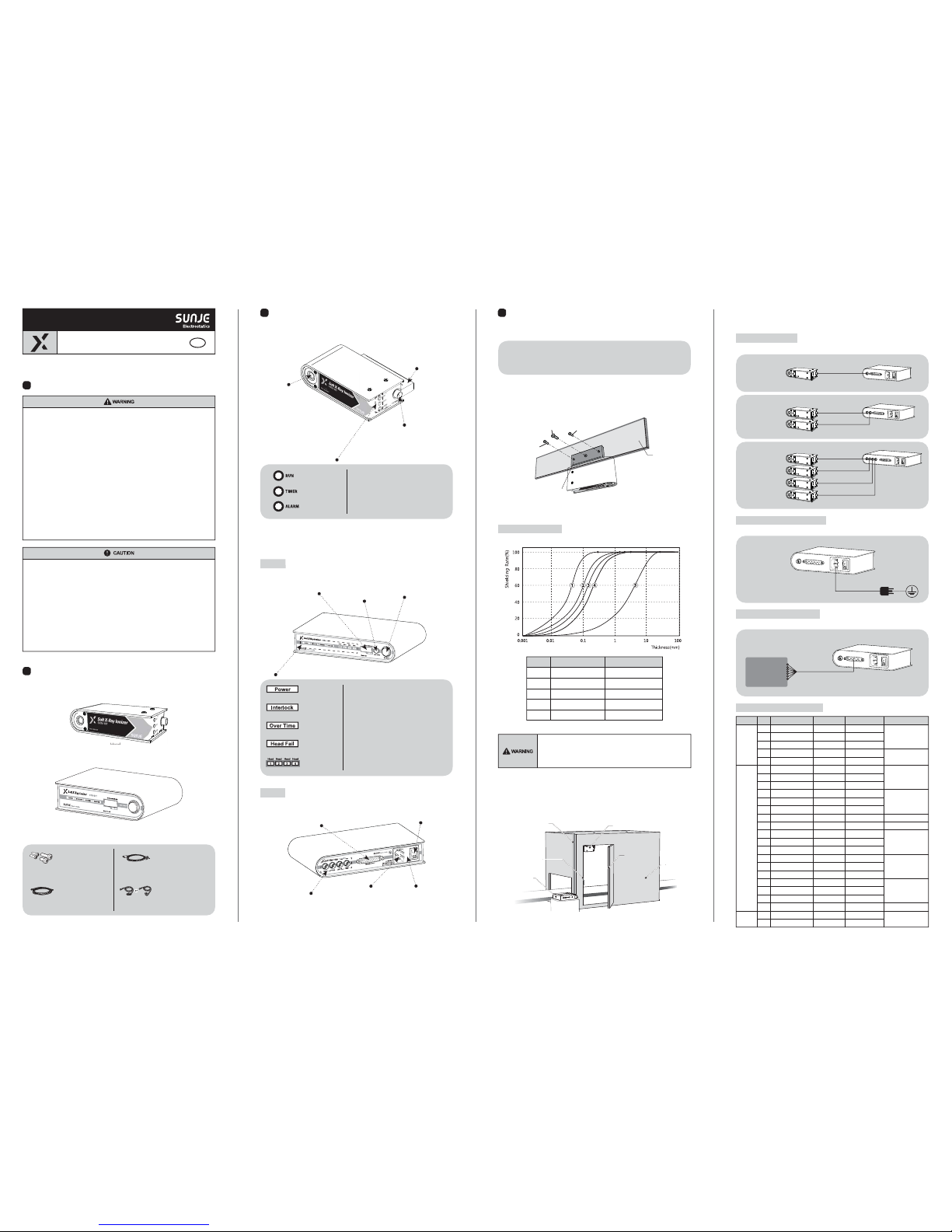
Check the package contents
▶ Product compositions
The package includes the following products composition.
1
The matters of safety
*
Do not fabricate or do maintenance by yourself. Malfunction, Electric shock, and fire danger are considered.
Contact us directly if you need the item to be repaired.
* Do not let the water touch the product. It may cause electric shock or fire due to malfunction.
* When you check or maintain the product, make it sure you turn off the power.
It may cause electric shock or fire due to malfunction.
* The item should be fixed to the target tightly. Electric discharging or breakage might happen.
* Please shield your installing circumstances first since the item releases the soft X-ray.
Direct X-ray exposure is not recommended owing to cause health problem.
* It includes a beryllium window on the X-ray tube unit in order to release soft X-ray for ionization.
This beryllium material can cause respiratory disorder only if the person gets exposed to forms of either
beryllium powder or smoke. However, our device doesn't creat beryllium in neither of the mentioned forms.
Please be careful not to break the device since there might be a slight chance that the device could partially
degrade into the powder form, then it can cause harm defects. If the user touches the beryllium material
on the device, clean oneself on the running water or rinse it off with soap directly.
If the beryllium windonw gets dirty or damaged, call us directly for assistance.
* Do not use the product at the place where dangerous material such as inflammable or ignitable
material exists. This product is not the product of anti-explosive type.
* This device is made only for industrial uses. You need to ground the device beforehand.
Otherwise, there are in case of malfunction, electric shock, or fire damage.
*
Do not disconnect the head cable with power applied. There is a possibility of electric shock or malfunction.
* Connect wires referring to the product manual. Wrong connection can cause failures.
* For your proper cable connection, take a look at the manual 「Installation & Connection」 for references.
Any disordered connection is detected, the malfunction might arise.
* All cables should be connected all the time. Please careful of cable disconnections. If power or
communication cables got damaged, replace them immediately. Malfunction and fire danger may happen.
* Do not install the device where the vibration can be detected.
Any minor impact or vibration on the device, the malfuction or danger of accident might happen.
* Do not use the item off the range of usage(Electrostatic elimination).
Malfunction or danger of accident may occur.
* If you wish to discard the head unit of X-ray device, you need to report for disuse declaration to the
institution(s) where they ask to. A proper declaration procedure is neccesary in order to disuse X-ray device.
* Please contact to either Korea Institute of Nuclear Safety(KINS) or a safety supervisor of Sunje directly.
It is recommended that only persons who have sufficient knowledge and experience such as system
designers and responsible persons deal with this product after carefully reading the product manual.
3
Nomenclatures of parts
Mounting Bracket
A bracket to fix
the item on the
facing target.
Indicator Light
Soft X-Ray Window
The X-ray radiation will be
released through this
beryllium window from the
head unit of X-ray ionizer.
Controller Connector
A connector to wire the
head unit and controller.
Operating indicator
Tube replacement
Alarm indicator
Malfunction Indicator
▶ Controller Unit(SXC-10T / 102T/ 104T)
※ The following is a standard image of SXC-104T. The image might differ according to other models.
▶ Head Unit (SXH-10T)
Front
indicator Light
LCD Display
Hours of Head use
and operation condition
will be displayed.
Signal Input/Output Connector
Use it when various signals
(input/output) are necessary.
Head Connector
A connector that
links the head unit
and controller.
Power Connector
Using it when
power supply.
Fuse Socket
When opening a socket, there is
a fuse inside. Please clarify your
proper specification when replacing.
Power Switch
A switch for supply/cut
the power.
Head Selection Button(102T, 104T only)
This is for when you want to
select an individual head from the
whole connections.
Run/Stop Button
It is a run/stop button
in order to operate
a soft X-ray Ionizer.
Blue LED will be on once the controller is powered on.
For user's safety purpose, Green LED will be on when
interlock is safely contacted. (If the light is not on, the
head unit is not in working condition)
Once the unit reaching 7,500hrs of operation,
Orange LED will be on.
when false operation, Red LED will be on.
Blue LED will be on the head you select among the
ones(Head1 or 2) are connected to a controller.
Power indicator
Safety(Interlock)
Indicator
Tube replacement
Alarm Indicator
Malfunction Indicator
Head Selection
Indicator
Rear
4
Installation and connection
■ Shielded room
■ There must be no objects between the
target area and X-ray device.
■ No vibration on the fixed device.
■ Be aware of any flammable or ignitable
materials around the working area.
■ Secure to have enough working space for
quick maintenance of the device.
▶ Check the installation conditions head unit
Please check the installation condition whether it meets proper specification.
▶ Head unit fixing
Fix the target product on the fixed area where you install by using supported fixing bolt(s).
See the following graph for references. Select the ideal tickness and quality of shielding material.
* Please shield the area where the customer is willing to install the soft X-ray device
for safety issue.
* After shielding process, please connection to your own interlock system to operate
the X-ray device On/Off when the door is opened/closed.
▶ Shield installation compositions
Please refer to the "Installation Compositions" for your references. Please keep your working
environment of the leakage radiation level within the range of 10μSv/hr all the time.
No. Shield Material Thickness [mm]
①
Copper Over 0.4
②
Aluminium Over 2.0
③
Glass Over 3.0
④
PVC Over 5.0
⑤
Acrylic Over 40.0
Head Cable
Interlock
Controller
Head Unit
Shield Door
Shield
▶ Shielding methods
Shielding material selection
Please connect the head and controller unit with supported "Head Cable".
▶ How to connect
Connecting the Head Unit
Using supported ground and power cables to connect the controller.
Connecting the Earth Ground and Power
Please connect the controller and external machinery equipment with supported "D-Sub Cable".
Connecting the Input & Output Signal
Input/Output Signal Cable Specifications
Division No. Pin Name Labeling Color Function
INPUT
1
2
3
4
5
6
7
8
9
10
11
12
13
14
15
16
17
18
19
20
21
22
23
24
25
Remote On
Remote Off
Common
Interlock
Interlock
Remote(N.O)
Remote(Com)
Remote(N.C)
Interlock(N.O)
Interlock(Com)
Interlock(N.C)
Not Used
Ground
Power (N.O)
Power (Com)
Power (N.C)
Over Time (N.O)
Over Time(Com)
Over Time (N.C)
Alarm (N.O)
Alarm (Com)
Alarm (N.C)
Not Used
Rs-485(+)
Rs-485(-)
RMT-ON
RMT-OFF
RMT-COM
INT-ON
INT-OFF
RE-N.O
RE-COM
RE-N.C
IN-N.O
IN-COM
IN-N.C
-
-
POW-N.O
POW-COM
POW-N.C
HEAD-N.O
HEAD-COM
HEAD-N.C
AL-N.O
AL-COM
AL-N.C
-
RS-485+
RS-485-
Black
White on Black
Brown
White on Brown
Red
White on Red
Orange
Black on Orange
Yellow
Black on Yellow
Green
-
Black
White on Green
Blue
White on Blue
Violet
White on Violet
Gray
Black on Gray
White
Black on White
-
Pink
Sky Blue
Remote
On / Off
(Electrical Contact )
Interlock
On / Off
(Electrical Contact )
OUTPUT
Remote
On / Off
State Output
Interlock
On / Off
State Output
-
-
Power
On / Off
State Output
Over Time
State Output
Alarm(Head Fail)
State Output
-
RS 485
RS 485
Communication
▶ Set the address
If you want to control the devices at once through RS-485(using communication function), then the proper
addresses should be addressed. You can set the address up to #16. (Address setting range: #1 ~ #16)
Entering to Address Mode
<Controller> <Controller>
On
Off
Close Open
<Interlock On> <Interlock Off>
05 06
※ Rated load (for Output) : 0.5A at 30V DC
<Controller>
<Controller>
<Controller>
<Controller>
<Controller>
<Remote On>
<Power On>
<(Head Fail) Alarmed>
<Interlock On>
<(Over Time) Alarmed>
07
▶ Head Unit (SXH-10T)
▶ Controller Unit(SXC-10T / 102T / 104T)
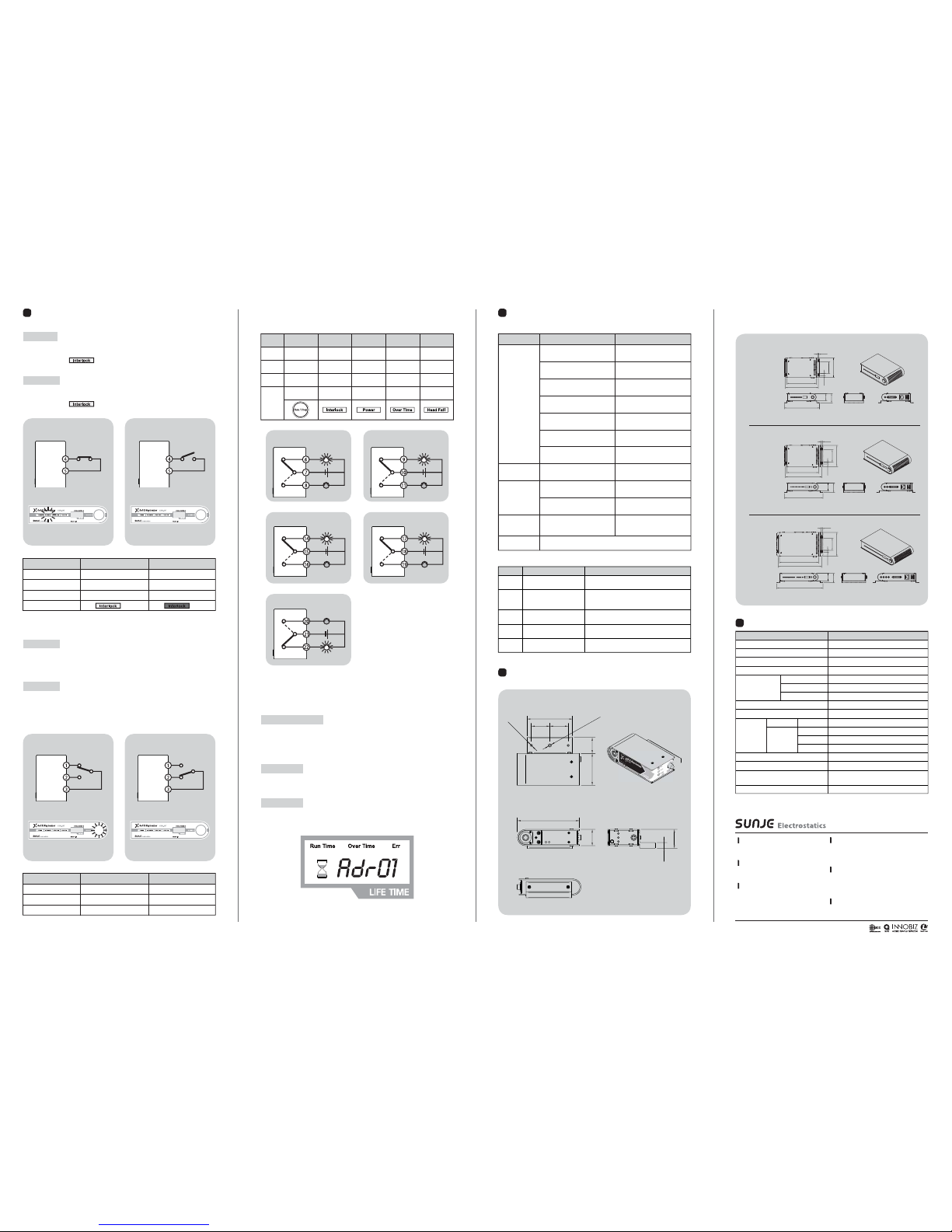
7
Dimensions
8
Specification
08
※ The appearance and specification of the product may be changed without prior notice for the improvement of the product.
Parameter
Ion Generation Method
Source
Beam Angle
Input Power
1:1 Type
1:2 Type
1:4 Type
Controller Fuse
Operation Circumstance
SXH-10T
SXC-10T
SXC-102T
SXC-104T
Dimensions
Alarm Function
Power
Consumption
(with Head)
Weight
Head
Controller
Description / Value
Soft X-ray
Soft X-ray Tube
150˚(decay time within 1sec. at 100mm)
AC 100~240V, 50/60Hz
23W
40W
50W
250V, 3A, 5X20 Glass Type Fuse
0℃ ~ +50℃(32℉ ~ 122℉), 35% ~ 85% RH
0.29kg
0.47kg
0.60kg
0.88kg
Please Refer to Dimension Drawing
Head Fail, Head Communication error
1 year
(Run, Alarm, Power, Over Time, Remote, Interlock)
Remote On/Off, Interlock On/Off, Output State
Warranty
Interface
※ Run/Stop button is available only when you are not using the remote.
Press Run/Stop for 5 sec. after the controller is powered(Power LED On), you will be entering to the
address setting mode.
※ The entrance of address mode is enabled only if the interlock is in off condition.
Please check whether the interlock LED is set to off.
Assign Address
Address Setting
Once you get into the address mode, the address number sequentially changes from #01 to #16
when you press Run/Stop button promptly.
Wait for 5 sec. after assigning address, then your address is set correctly and automatically exits the
address mode.
< Address Mode >
<Side>
<Top>
<Rear>
<Front>
109.5
80.0
32.532.5
29.0
33.5
10.0
56.0 28.5
1/4 - 20 UNC
2-M4X0.7
If #4 and #5 of a D-Sub cable are connected, the interlock is on.
When LED is on, it shows that the door is securely locked and totally shielded.
"Interlock indicator ( )" light will be blink in the front of the controller.
If #4 and #5 of a D-Sub cable are disconnected, the interlock is off.
When LED is off, it shows that the door is securely unlocked and not shielded well.
"Interlock indicator ( )" light will be turned off in the front of the controller.
5
How to set
▶ Set the interlock
Interlock On
Interlock Off
<Controller Indicator Light> <Controller Indicator Light>
Article
D-Sub Cable No.
State
Meaning
Controller Indicator Light
Interlock On
4 - 5 Close
The shield door is closed
Normal operation standby
On
Interlock Off
4 - 5 Open
The shield door is open
Abnormal operation standby
Off
Set-up interlock before setting remote. If the interlock is in off, the head unit will not operate even
though the remote is on.
If #2 and #3 of a D-Sub cable are connected, the remote is off.
Remote off indicates that the head unit is not operating.
▶ Set the remote
Remote On
Article
D-Sub Cable No.
State
Meaning
Remote On
1-3 Close
Head starts operating
Ion starts forming
Remote Off
2-3 Close
Head stops operating
Ion stops forming
<Controller Indicator Light>
<Controller>
Off
Close
<Remote Off>
<Controller Indicator Light>
<Controller>
On
Close
<Remote On>
▶ Output status signal
category
6-7 Close
Remote On
Ion Forming
14-15 Close
Power On
Power applied
(Over Time) Alarm
Status Output
(Head Fail)
Status Output
D-Sub
Cable No.
17-18 Close
21-22 Close
Status
(Over Time)
Alarmed
(Head Fail)
Alarmed
Meaning
Head Unit
Malfunction
Controller
Indicator
Run/Stop
Indicator On
Tube Replacement
Alarm Indicator On
Malfunction
Indicator On
9-10 Close
Interlock On
Remote
Status Output
Interlock
Status Output
Power
Status Output
Normal Operation
Standby
Interlock
Indicator On
Power
Indicator On
Head Unit:
7,500 Hrs of use
Remote Off
6
Problem solving
▶ Checklist before called
Problem Identifying Problem Solution
Not Operating
Please re-plug the power cable
and then turn the device on again.
Was the proper voltage level applied
for this set-up?
Please use the proper level of power
input for the device.
(AC 100~240V, 50/60Hz)
Is the swith off at back
of the Controller?
Turn on the power switch.
Is a fuse broken? Replace the proper fuse immediately.
Is there any alarm LED on the
head unit of device?
Purchase and replace
the tube unit(replaceable).
Is remote off?
Clear the remote off corresponding
to 「Remote Setup」 manual.
Is Interlock off?
Check whether the cable connection
is properly done.
No Signal
Have you followed the proper procedure
for Input/output signal cable(s)
Place Interlock on corresponding to
「Interlock setup」 manual.
Decreased
Performance
Error code displayed on
the Controller LCD panel
Can't possibly ground the device?
Head unit not working
(when pressing Run
button on the controller)
Is the remote off control
on your machine?
See from manual for [Error code Verification].
Clear the Remote off
on your machine.
Is your power cable still plugged in?
Any damages or cut on the cables?
You need to replace the cables
if it gets cut or damaged.
Please refer to 「Installation & Connection」
for(proper) grounding the device.
Error Code Status Solution
Err 1
Err 2
Err 3
Err 4
Err 5
Check the connectivity of output cable
Check the status of head cable connection.
Replace the cable if head cable gets cut or damaged.
Turn the power off and restart it again..
Replace the power module of the head unit.
Contact us immediately.
Initial synchronization false
of head unit and controller
Disconnecting communication
error due to wire separation or
breakage of communication cable
Hours of head unit usage
information reception error
Ionization level of the head unit is
lower than the minimum current
An excess current detected when
the time change of head unit
Replace the tube module of the head Unit
Contact us immediately.
▶ Error code verification
1:1 Type
Controller
(SXC-10T)
1:2 Type
Controller
(SXC-102T)
1:4 Type
Controller
(SXC-104T)
162.5
181.0 ±0.5
66.0
12.0
106.0
6.0
41.0
52.0
193.0 ±0.5
174.5
200.5 ±0.5
66.0
12.0
116.0
6.0
41.0
52.0
212.5 ±0.5
253.5 ±0.5
41.0
52.0
215.0
241.5 ±0.5
66.0
12.0
131.0
6.0
Copyright 2018. SUNJE Hi-Tek Co., Ltd. All Rights Reserved.
Sunje (SHANGHAI) Trading Co.,Ltd.
Block C, 4F, No.482, Hongxu Road, Minhang District,
Shanghai, China
T) +86-21-5433-9761 F) +86-21-5433-9762
Sunje Technology Co., Ltd.
2F, No.6, Lane.102, Sinhe Rd, Sinfong Township,
Hsinchu County, Taiwan 30472
T) +886-3-568-7891 F) +886-3-568-7950
Sunje Japan Co., Ltd.
3-11-16-321 Higashimikuni, Yodogawa-ku, Osaka, Japan
T) +81-6-4866-5202 F) +81-6-6399-9290
Head Office & Factory (Busan)
8 ,Cheonggwang-gil, Ilgwang-Myeon, Gijang-Gun,
Busan, Korea
T) +82-51-720-7500 F) +82-51-720-7501
Southern Sales Office (Chilgok)
35-2, Seojungni 3-gil, Seokjeok-eup, Chilgok-gun,
Gyeongsangbuk-do, Korea
T) +82-54-476-9033 F) +82-54-476-9034
Central Sales Office (Hwaseong)
3F, Ilshin B/D, 4, Namnyeoul 2-gil, Hwaseong-si,
Gyeonggi-do, Korea
T) +82-31-203-9034 F) +82-31-202-9034
Customer Center +82-70-7714-9033
Sales Contact +82-31-203-9034
www.sunstat.com
 Loading...