

Sunje SRB-1300, SRB-1200, SRB-1100, SRB-1800, SRB-1600 Instruction Manual
...
It is recommended that only persons who have sufficient knowledge and experience such as system
designers and responsible persons deal with this product after carefully reading the product manual.
1
The matters of safety
01 02 03
Instruction Manual
SRB Series
Eng
04
2
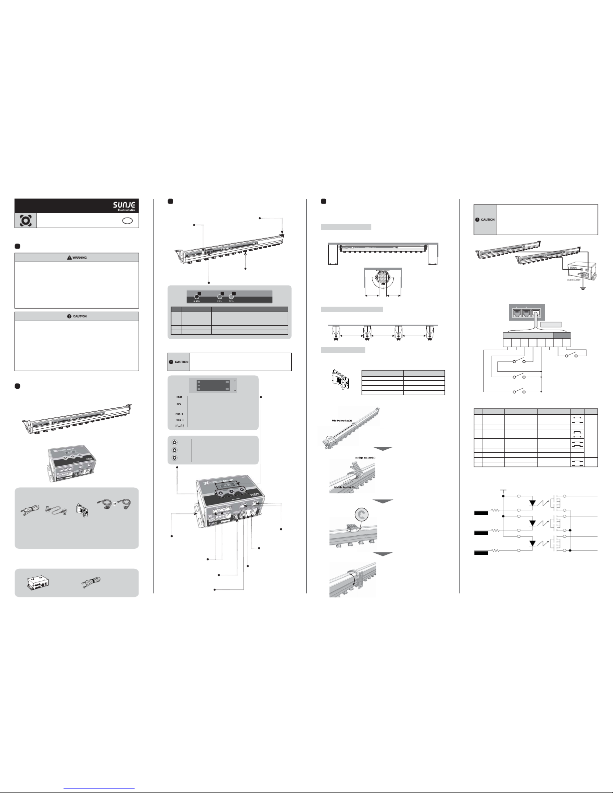
Check the package contents
▶ Product compositions
The package includes the following products composition.
Ion Bar
SRB Series / 2ea
Power Controller
SRC-2P / 1ea
3
Nomenclatures of parts
▶ Ion Bar (SRB Series)
Discharge Needle
The needles for
generating +/- ions.
Indicator Light
Side Bracket
A bracket to fix the item
on the facing target.
Mounting Bracket
The bracket for
mounting SRC-2P.
Input Terminal
This terminal is for
controlling and power
supply of a ion bar.
Output Terminal
This terminal is for controlling
and power supply of a ion bar
#1 and #2.
4
Installation and connection
▶ Ion bar installation
When you install the ion bar, Please check the distance between ion bar and object.
※ Please, handle with care when you carry or install not to break or bend an ion bar.
If there is any conductive object close to ion bar, SRB Series may not operate properly.
Please install it with reference to figure below.
Interference by Grounding Matters
Side to Side Installation (More than two sets)
When the more than two ion bars are installed, to avoid interference,
the range between two ion bars should be more than 400mm.
Min 400mm Min 400mm Min 400mm
Installation by Middle Brackets
The middle bracket is used to protect bending problem by the weight of ion bar. Please fix the middle
bracket with M4 bolts. The number of supporting middle bracket will differ from the models.
Middle Bracket
※ Ion Bar Middle Bracket Quantity
SRB-1100 ~ 1300
SRB-1500 ~ 1800
SRB-2000 ~ 2300
SRB-2500 ~ 3200
-
1ea
2ea
3ea
Model Middle Bracket Quantity
▶ Power Controller (SRC-2P)
▶ Option
If you require extra functions with the basic accessories we provided, you need to purchase optional
items in below for further assistant.
Signal Cable
SUC-MT-2-001
10m
RMS Controller
RMSU
1 32
Display
Can check the status of
the ion bar's operation.
RMS(Real Monitoring System)
Communication Terminal
Used to RMS(Real Monitoring System)
communication.
Power Switch
The switch to turn on/off the power.
Fuse
250V, 1A Glass Type
Power Input
Used to power supply.
(AC 100V~240V, 50/60Hz)
Ground Terminal
Used to connect the ground cable.
Settings Buttons
Min 200mmMin 200mm
90.0°
90.0°
Min 150mmMin 150mm
* If the equipment is used in a manner not specified by the manufacturer,
the protection provided by the equipment may be impaired.
* Do not let the water touch the product. It may cause electric shock or fire due to malfunction.
* When you check or maintain the product, make it sure you turn off the power.
It may cause electric shock or fire due to malfunction.
*
Secure the product firmly when you want to secure it. There is a possibility of accident due to fall-over or malfunction, etc.
*
Secure working space when you install the product. If working space is not secured, the checking or maintenance of
the product is made impossible leading to failure of the product.
* Do not use the product at the place where dangerous material such as inflammable or ignitable material exists.
This product is not the product of anti-explosive type.
* This device is made only for industrial uses. You need to ground the device beforehand.
Otherwise, there are in case of malfunction, electric shock, or fire damage.
*
Do not contact the discharge needle or terminal with power applied. There is a possibility of electric shock or malfunction.
* Handle the discharge needle with care as its tip is very sharp.
* Connect wires referring to the product manual. Wrong connection can cause failures.
*
Take precautions as cables of the adaptor, the power line and communication line of each product may disconnect.
If the cable is damaged, replace it immediately.
* Do not install the device where the vibration can be detected.
Any minor impact or vibration on the device, the malfuction or danger of accident might happen.
* Do not use the product for the purpose outside of the range of the product use.
If the product is used for the purpose outside of the range of the use,
it can result in the trouble or the shortened service life. Or an unexpected problem may occur.
* The ionizer generates ozone(below 0.05ppm).
If you sense the smell of ozone when you use more than two units, ventilate the air.
* When installing or transporting the ion bar, be prepare not to bend the item during the process.
*
Please try to input your power connection with an exclusive power controller(SRC-2P)
of SRB Series.
*
The composition of a package(1set) can be consisted of a controller and two ion bars.
We recommand you to purchase and install as a package as a unit.
NO
1
2
3
Alarm LED
POS(Positive) LED
NEG(Negative) LED
When H/V unit has some problem to generate high-voltage,
alarm LED is turned on.
(When it shows the difference more than about ±30% with setting value.)
(+) high voltage normal operating signal.
(
-
) high voltage normal operating signal.
Name Function
When H/V unit has some problem to generate high-voltage,
H/V LED is turned on. (When it shows the difference
more than about ±30% with setting value.)
The LED for RMS(Real Monitoring System) operating.
(+) high voltage normal operating signal.
When H/V unit has some problem to generate high-voltage.
(-) high voltage normal operating signal.
H/V
NEG
POS
RX/TX
8.8.8.8.
UP
DOWN
SET
Use it when you increase the setting value.
Use it when you decrease the setting value.
This button is used for various settings.
(Address, Output Time, Output Voltage)
■ Middle Bracket Installation
a. Adjust a "Middle Bracket(B)" to set an ion bar in your
expected area of installation.
b. Assemble "Middle Bracket(T)" and
"Middle Bracket Pin" as shown in the figure.
c. Place two "E rings(Middle Bracket Pin fixing)" into a
"Pin side" to install a middle bracket.
d. After assembling a middle bracket, face the ion bar
using a middle bracket that can point to the proper
target area.
E ring
(Middle Bracket Pin fixing)
Ground Cable
Length : 1m / Ø4-Ø4[mm]
Output Cable
Max Length : 10m
Output Cable
Max Length : 10m
* If you use a power controller without an exclusive SRB Series componenet,
it might cause product malfunction.
* The composition of a package(1set) can be consisted of a controller and two ion bars.
If you only use one ion bar to the specified controller, it might not function properly.
We recommand you to purchase and install as a package as a unit.
* The maximum installation length from an ion bar to controller is 10 meter.
If it exceeds, it might not function properly.
▶ How to connect the power controller
▶ Interface
▶ Circuit (Photo Relay Output)
INTERFACERMSLINK
Not Used
Remote
(Close : Stop, Open : Run)
Run/Stop State
(Close : Run, Open : Syop State)
H/V Abnormal 1
(Close : Alarm, Open : Normal)
H/V Abnormal 2
(Close : Alarm, Open : Normal)
1 2 3 4 5 6 7 8
Remote, Alarm
Output Input
Not Used
No RemarksColor Function Input / Output
Run/Stop State
Photo Relay Output
(Run-Close, Stop-Open)
Photo Relay Output
(Normal-Open, Alarm-Close)
Photo Relay Output
(Normal-Open, Alarm-Close)
Remote
(Close : Stop, Open : Run)
Not Used
Remote 1
Remote 2
Not Used -
Common
-
-
-
-
-
High Voltage Abnormal 1
High Voltage Abnormal 2
Picture
Output
Input
Orange
White & Orange
Green
Blue
White & Blue
White & Green
3
4
6
7
8
2
1
5
White & Brown
Brown
Normal
Alarm
Run
Stop
Normal
Alarm
Run
Stop
※ The device must be grounded to prevent electric shock in order to function well.
RUN/STOP
H/V Alarm 1
H/V Alarm 2
+5V
1. Run/Stop State
3. H/V Abnormal Alarm 1
4. H/V Abnormal Alarm 2
5. Common
Power Cable
SPC-MT-1-001
AC 100V, 50/60Hz, 1.8m / 1ea
or
Power Cable
SPC-MT-2-001
AC 220V, 50/60Hz, 1.8m / 1ea
*
*
Output Cable
SOC-RB-1-001
10m / 2ea
Middle Bracket
SBR-B7-2-001
0~3ea
Ground Cable
SGC-MT-2-001
1m /Ø4-Ø4[mm]
/ 1ea
▶ Power Controller (SRC-2P)
05 06 07 08
8
Dimensions
▶ Ion Bar (SRB Series) / Power Controller (SRC-2P)
9
Specification
※ The appearance and specification of the product may be changed without prior notice for the
improvement of the product.
Input Power
Power Consumption
Current Consumption
Ion-Generation Method
Electrode Material
Electrode Replacement
Operation Circumstance
Dimensions
Function
Alarm Function
Interface
Mounting Method
Warranty
AC 100 ~ 240V, 50/60Hz
Max. 15W
Max. 68mA
Corona Discharge Pulse AC
Tungsten
Cartridge type
0℃ ~ +50℃(32℉ ~ 122℉), 35% ~ 85% RH
See the accompanying drawing paper
Remote Control
Positive 1 ~10 Sec. / Negative 1 ~ 10 Sec.
Positive 4 ~ 11kV / Negative 4 ~11kV
H/V Abnormal
Run, Stop, RS-485, Alarm(H/V Abnormal)
Bolt Mounting with Bracket
1 year
AC 220V
Level V0
RJ45
SRB Series
SRC-2P
Non-Flammable ABS
EGI
Parameter Description / Value Remarks
Period [Sec.]
Voltage [kV]
Main Body Material
Adjust
Function
FRONT SIDE
TOP
110.0
122.5
177.0
51.5
71.5
95.0
20.0
6.0
160.0
190.0
81.0
75.0
▶ Ion Bar (SRB Series)
BOTTOM
FRONT SIDE
TOP
±2.5
C
±2.5
D
40.0
65.0
78.0
10.0
18.0
40.0
4-Ø5X9L SLOT HOLE
2-Ø5X10L SLOT HOLE
49.0 49.0
60.0
A
±2.5
B
77.5
89.2
46.0
Settings
5
How to set
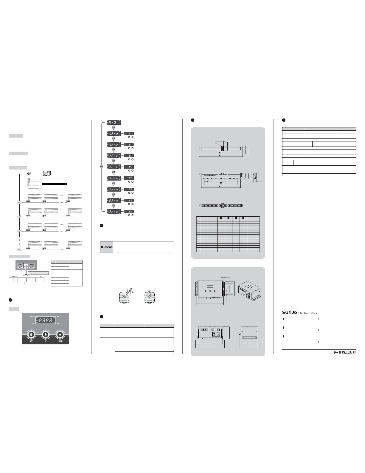
▶ SRC-2P
a. Max. 4,096 sets of ion bar.
b. Real Time Monitoring of ion bar condition. (Signal checking cycle : max. 1min)
c. Record, revise and cancelation of managed history by operator.
d. Ion bar checking and abnormal history.
RMS Features
RMS Configuration
RMS UTP Specifications
a. Provide fine display view.
b. Equipment ID, equipment name, maker, ion bar state, maintenance history.
c. Detailed data checking in several groups.
Monitoring Function
No Color Descriptions
Not Used
Not Used
RS-485+
RS-485-
Orange
White & Orange
Green
Blue
White & Blue
White & Green
3
4
6
7
8
2
1
5
White & Brown
Brown
▶ RMS (Option)
Monitoring operation and abnormal conditions of the installed ionizer for static elimination in real time from the PC connected to the network management system that can fit a large amount of
static electricity; trends for operating device in the management of unmanned removing is highly
recommended for the customers.
INTERFACERMSLINK
RS-485+
RS-485-
1 2 3 4 5 6 7 8
RMS(Real Monitoring System)
Power Controller #1
Address #01 Address #02 Address #16
Address #01 Address #02 Address #16
Address #01 Address #02 Address #16
Address #01 Address #02 Address #16
Power Controller #2 Power Controller #16
Power Controller #1 Power Controller #2 Power Controller #16
Power Controller #1 Power Controller #2 Power Controller #16
Power Controller #1 Power Controller #2 Power Controller #16
RMSU
RMSU
RMSU
RMS Controller #1
RMS Controller #2
RMS Controller #3
RMS Controller #32
RMSU
1 Group
2
3
4
5
6
7
8
Group
PC
Maximum Set : 8 Groups, 4,096 Set
MULTI-PORT
(8 Port)
< SRC-2P Controller Panel >
Maintenance is an essential item for maintaining its capacity. Please conduct a routine
maintenance according to the below description. The life time of a discharge needle can be a
difference depending on using circumstance. SRB Series needs a routine maintenance and
cleaning in case of bad circumstance. (high humidity or dust)
▶ Discharge needle cleaning
The contamination level of discharge needle is different among the areas where the user installs,
please maintain own cleaning period that suits your environment.
▶ Discharge needle cleaning order
a. Be sure to power off before cleaning the ion bar.
b. Soak the cotton swab with alcohol. (do not use acetone)
c. Put the swab on the discharge needle and wipe it turning the swab right and left.
(take precautions not to apply severe force to the discharge needle.)
d. Replace the damaged discharge needle.
e. After the cleaning, let the alcohol applied to the discharge needle surface evaporate completely
and then operate the ion bar.
f. Please record the cleaning process as a reference in the file.
▶ Discharge needle maintenance
If the discharge needle broken or severely damaged, please replace the needle socket immediately.
6
Maintenance
※ After setting the device, the set value is automatically
saved in 3 seconds.
Address Set Up / Running
- The possible setting range for communication address is 1~16.
-
Press up/down buttons to select the expected address which you are willing to use.
※ To set "Address", you need to set channel(#1 & #2) first.
Positive(+) Time[sec.] Set Up (Channel 1)
- Setting range for Positive(+) Time is 1~10 seconds.
- Press up/down buttons to select proper output time.
Negative(
-
) Time[sec.] Set Up (Channel 1)
- Setting range for Negative(
-
) Time is 1~10 seconds.
- Press up/down buttons to select proper output time.
Positive(+) Time[sec.] Set Up (Channel 2)
- Setting range for Positive(+) Time is 1~10 seconds.
- Press up/down buttons to select proper output time.
Negative(
-
) Time[sec.] Set Up (Channel 2)
- Setting range for Negative(
-
) Time is 1~10 seconds.
- Press up/down buttons to select proper output time.
Positive(+) Voltage[kV] Set Up (Channel 1)
- Setting range for Positive(+) Voltage is 4~11kV.
- Press up/down buttons to select proper output voltage.
Negative(
-
) Voltage[kV] Set Up (Channel 1)
- Setting range for Negative(
-
) Voltage is 4~11kV.
- Press up/down buttons to select proper output voltage.
Positive(+) Voltage[kV] Set Up (Channel 2)
- Setting range for Positive(+) Voltage is 4~11kV.
- Press UP/DOWN buttons to select proper output voltage.
Negative(
-
) Voltage[kV] Set Up (Channel 2)
- Setting range for Negative(
-
) Voltage is 4~11kV.
- Press up/down buttons to select proper output voltage.
▶ Checklist before called
7
Problem solving
The product
does not work
Is your power cable still plugged in?
Please re-plug the power cable
and then turn the device on again.
Was the proper voltage level applied
for this set-up?
Please use the proper level of power
input for the device.
(AC 100~240V, 50/60Hz)
There is no
ionization
Is there any conductive material
around the device?
Please refer to 「Installation & Connection」 for
setting the proper target distance from device.
Does the installed environment have too
high/low level of humidity or temperature?
Please install the device upon
the proper working specification.
The ionizing
performance
has been
decreased.
Any damages or cut on the cables?
You need to replace the cables
if it gets cut or damaged.
Any contamination on the discharge needle?
Please refer to 「Maintenance」 for
cleaning the discharge needle.
Problem Identifying Problem Solution
*
This device uses the high level of voltage. When operating maintenance, please power off
and unplug the device. Otherwise, there might be in case of electric shock or fire damage.
* The discharge needle is very sharp at the edge.
Do not phsically(directly) touch the discharge needle.
Copyright 2017. SUNJE Hi-Tek Co., Ltd. All Rights Reserved.
Sunje (SHANGHAI) Trading Co.,Ltd.
Room 312, Jiurun Business Building 3rd Floor,No. 298,
Yindu Road, Xuhui District, Shanghai, China 200000
T) +86-21-5433-9761 F) +86-21-5433-9762
Sunje Technology Co., Ltd.
2F, No.6, Lane.102, Sinhe Rd, Sinfong Township,
Hsinchu County, Taiwan 30472
T) +886-3-568-7891 F) +886-3-568-7950
Sunje Japan Co., Ltd.
3-11-16-321 Higashimikuni, Yodogawa-ku, Osaka, Japan
T) +81-6-4866-5202 F) +81-6-6399-9290
Head Office & Factory (Busan)
8 ,Cheonggwang-gil, Ilgwang-Myeon, Gijang-Gun,
Busan, Korea
T) +82-51-720-7500 F) +82-51-720-7501
Southern Sales Office (Chilgok)
35-2, Seojungni 3-gil, Seokjeok-eup, Chilgok-gun,
Gyeongsangbuk-do, Korea
T) +82-54-476-9033 F) +82-54-476-9034
Central Sales Office (Hwaseong)
3F, Ilshin B/D, 4, Namnyeoul 2-gil, Hwaseong-si,
Gyeonggi-do, Korea
T) +82-31-203-9034 F) +82-31-202-9034
Customer Center +82-70-7714-9033
Sales Contact +82-31-203-9034
www.sunstat.com
1
2
3
4
5
6
7
8
9
10
11
12
13
14
15
SRB-1100
SRB-1200
SRB-1300
SRB-1500
SRB-1600
SRB-1800
SRB-2000
SRB-2100
SRB-2200
SRB-2300
SRB-2500
SRB-3000
SRB-3200
SRB-3400
SRB-3600
1020
1140
1260
1380
1500
1740
1980
2100
2220
2280
2520
2940
3120
3300
3480
1118
1238
1358
1478
1598
1838
2078
2198
2318
2378
2618
3038
3218
3398
3578
1160
1280
1400
1520
1640
1880
2120
2240
2360
2420
2660
3080
3260
3440
3620
1180
1300
1420
1540
1660
1900
2140
2260
2380
2440
2680
3100
3280
3460
3640
-
-
1
1
1
2
2
2
2
3
3
3
3
4
MODEL No. MIDDLE BKT Q’TY
18
20
22
24
26
30
34
36
38
39
43
50
53
56
59
TIP Q’TY No.
A
B C D
 Loading...